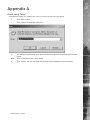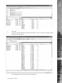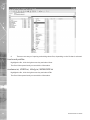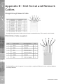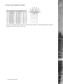
1
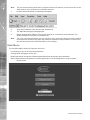
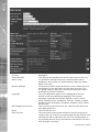
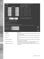
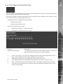
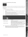
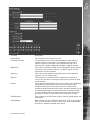
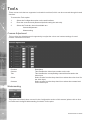
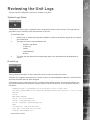
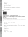
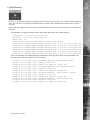
1.0001
Eco Range
Network Guide
Eco
Contents
Network Configuration ................................................................................................................3
Simple Configuration ..................................................................................................................5
Advanced Configuration ...........................................................................................................13
Tools ...........�
26
Reviewing the Unit Logs ...........................................................................................................27
Appendix A .�
31
Appendix B – .ini Files ..............................................................................................................32
Appendix D –Unit Serial and Network Cables ........................................................................36
Appendix E – IP Address Range and Subnets .......................................................................38
Index ...........�
2
42
Dedicated Micros ©2006
Eco
Network Configuration
This manual is designed to help with the advanced configuration of the unit using the on-board web
pages.
To assist with the configuration of the unit, sections are constructed as tutorials and will illustrate how
to perform common requirements. Use the tutorials that will provide the required functionality and
follow the step by step instructions.
In some of the sections the web interface and the OSD menus will be displayed. These are the more
advanced network settings where configuration via the web pages is more appropriate.
This manual will be divided into:
Simple Configuration –required to get the unit up and running
Advanced Configuration –project specific requirements
Note:
The unit should be configured in line with the main configuration steps detailed in the Setup
Guide and therefore the cameras inputs have been enabled and the standard record rate
has been set.
1.1001
Web Page Icons
Each of the unit configuration web pages has the following buttons:
1.1002
Reset to Defaults –This will return the associated page to factory defaults.
1.1003
Display Help –This will display the Help pages for the associated configuration page. This is a good
starting point if you are having problems or do not understand the configuration parameters.
1.1004
Save Settings –This will save a changes that has been made to the configuration page - remember
to save the changes.
NOTE: Selecting a new page before saving the changes will result in any changes being lost!
1.1005
Reset –This is displayed on configuration pages that require a unit reset to initiate a function.
Note:
Always save the settings before resetting the unit.
Each ‘How to.. Section’ will show the Tab and Function name to allow easy location of the correct
configuration page.
1.1006
1.2001
Accessing the Configuration Web Pages
The unit is configured using on the on-board web pages. To access these:
Dedicated Micros ©2006
3
Eco
Note:
The unit should already have been configured with an IP address (via the serial port or the
OSD menus) and connected to an Ethernet network.
1.
Launch Internet Explorer (or Netscape Navigator).
2.
Type the IP address of the unit into the address bar.
3.
The Main Menu page will be displayed.
4.
Select Configuration Options. The unit will prompt for a username and password. The
default settings are dm and web respectively.
The user name and password are case sensitive; they should be changed from the default
username and password and kept safe. Mislaid usernames and passwords could result in
the unit being returned to Dedicated Micros for resetting.
1.2002
Note:
1.3001
Main Menu
The unit Main Menu allows the Operator access to:
Live viewing of any of the connected cameras.
Configuration web pages for the unit.
Downloads which include the software applications and the product documentation.
Demo pages that demonstrate how viewing applications can be designed for varying system
requirements.
1.3003
2.0001
4
Dedicated Micros ©2006
Eco
Simple Configuration
How to Configure Global Parameters
There are some parameters that can be set that will affect the overall system; video standard for the
video inputs, browser format for the web interface, language that the menus will be displayed in and
the DST (daylight saving time) settings.
To configure these parameters:
1.
Select Home -> Main Set-up.
2.
Select the video standard from the drop down list; this will be the standard for all the video
inputs on the unit.
It is necessary to carry out a system reset if the video format is changed before saving the
settings. This allows the unit to activate the change.
Note:
3.
Select the date format from the drop down list.
4.
The unit web pages can be viewed in two formats; Active X (default) or Java, select the
relevant option from the drop down list.
5.
The web configuration pages for the unit can be displayed in a selection of languages,
select the language which is most appropriate to your installation from the drop down list.
Ensure the PC being used for the configuration is set to the correct time zone and that DST
is enabled before continuing.
Note:
6.
Select the DST for region where the unit is installed from the drop down list.
7.
If the settings are incorrect reset the unit by selecting the reset button.
8.
If the unit time is to be synchronised to the PC that is being used to configure the system
then select sync unit time from PC. Note this only synchronizes the time when the button is
selected this will not maintain synchronisation permanently.
9.
Remember to save the configuration by selecting Save Settings!
2.0003
Dedicated Micros ©2006
5
Eco
Function
Video Standard
Date Format
Browser Settings
Language
DST Daylight Saving Time.
Reset
Sync unit time
Description
This displays the standard used by the video inputs on the unit.
It is possible to identify the format in which the date will be
displayed in the browser; the default setting is Day Day, Month
Month, Year Year.
The browser interface supports ActiveX or Java. Select the most
appropriate for your application from the drop down box. This
is a global setting so any user connecting to the system will be
presented by the same interface.
The unit configuration pages can be displayed on the local
browser in the most appropriate language.The currently
languages supported are; English, Spanish, French, Czech,
Italian, Russian, Dutch, Portuguese, German, Turkish, Croatian,
Danish, Finnish, Norwegian, Hungarian, Swedish, Polish, Arabic
and Chinese
This is the time zone local to the unit, select from the list for the
most appropriate time
This will reset the unit
The unit can be synchronised with the PC that is being used to
configure the unit. If the PC is synchronised with the network clock
then this time will be reflected in the unit. The synchronisation is
not persistent and will only synchronise the unit and the PC at the
time the button is pressed
2.20011
6
Dedicated Micros ©2006
Eco
How to Configure Video Inputs and Standard Record Settings
Each of the video inputs on the unit can be individually configured.
This section will describe the full configuration process including resolution and file size, camera
titles, setting a camera to mono, camera fail notification and standard recording settings.
1.
Select Cameras -> Camera Set-up
2.
It is possible to identify the global camera resolution (common to all video input) the current
option sets the resolution to 704 x 256.
3.
Select the required image resolution, enter a file size of between 2K & 45K.
See the Setup Guide for the recommended settings.
Note:
4.
All connected cameras will be automatically enabled, use this screen to check the enabled
inputs are correct.
5
In the corresponding title box enter the camera name for the video source connected to that
input.
6.
Use the drop down box to select whether alarm input polarity is Normally Open, Normally
Closed or Off for each camera alarm.
7.
By default the unit presumes all enabled inputs are colour video sources. If you are
connecting a monochrome signal to the unit, it is recommended that the input be set for
mono. Place a tick in the corresponding video input.
8.
To enable the unit to send notification that the video input does not detect a 1V peak to
peak signal place a tick in the box below Cam-Fail Reporting. This can send a camera fail
email.
9.
Save the configuration by clicking the Save icon.
Dedicated Micros ©2006
7
Eco
Function
Pictures/Second / milliseconds
Live/Record Resolution
Image Size
Video Expiry Period
Connected
Title
Alarm Input Polarity
Mono
Camera Fail Reporting
8
Description
This allows the record settings to be configured as either Pictures
Per Second or Milliseconds
This is the resolution of the live and recorded images (MPEG only)
that will be transmitted from the unit and recorded to hard disk.
This is the file size for the image to be recorded, between 2KB &
45KB.
This indicates the maximum time any images can be stored on the
hard disk, if the record duration is greater than the video expiry
period the images will automatically be overwritten
The unit can automatically detect if a camera source is present,
the corresponding input will be enabled in this menu for connected
cameras.
It is possible to allocate an ASCII camera title to each of the
cameras, which will be displayed onscreen along with the camera
number.
This can be set to Off, Normally Open (NO) or Normally Closed (NC).
If the video input on the unit has a black and white (monochrome)
source connected then enable the corresponding camera.
The unit will try and compress the colour contents of the image if
this box is not enabled, ticking this box will remove unnecessary
overhead on the compression process.
If the video input on the unit does not identify a 1V peak-to-peak
signal then the unit can transmit an alarm notification email for
camera failure on the corresponding video input.
Dedicated Micros ©2006
2.20021
This will display a thumbnail view of video connected to the unit.
Place the cursor in the camera title box to view the corresponding
video input.
To configure the standard record settings
10.
The record duration and standard record rate are inter-connected; changing one of these
settings will automatically update the other.
11.
Enter the information in either the record duration or standard record rate. These are global
settings across all cameras for the schedule period being edited.
Eco
Click here to see thumbnail images
Either
Enter the Record Duration for when the unit in the selected schedule period
Or
Enter the Standard Record Rate for the selected schedule period.
12.
Select the alarm recording mode to reflect the recording requirement on receipt of an alarm.
13.
Select the Event Active option from the drop down list
Running the unit at maximum Record Rate (25pps or 40ms in Standard Record Settings)
will affect viewing and network transmission, as the video codecs will be operating close
to capacity - the unit’s priority is to record the footage to the internal HDD, so transmission
performance will be reduced. This is exhibited by slow connection to the html pages and
reduced viewing frame rates. Multi-user viewing will also be affected. It is not recommended
to set the Standard Record rate to 20ms for everyday usage, but rather only for specific
situations where this rate is necessary.
Note:
Record Duration
Standard Record Rate
Alarm Record Rate
Event Active
The total record time available in (DD) Days and (HH) Hours. This
indicates the storage capacity of the system without any alarm
recording. It is estimated from size of video storage, the standard
record rate and the requested target size of the recorded images.
Note: Changing the Record Duration will automatically update the
Standard Record Rate. Changing the Standard Record Rate will
likewise update the Record Rate. This should be configured for
day, night and weekend operation modes.
This is global setting and identifies the ‘common pictures per
second’ for all enabled video inputs in non alarm mode. This can
be set in milliseconds or the number of pictures per second.
The delay between consecutive images from any one camera is
the Standard Record Rate multiplied by the number of cameras
being recorded. Changing the Standard Record Rate will
automatically update the Record Duration. Changing the Record
Duration will likewise change the Standard Record Rate.
Example Record Rates
40ms = 25 pictures per second
50ms = 20pps
100ms =10 pps
125ms = 8pps
200ms = 5 pps
500ms = 2pps
1000ms = 1pps
This identifies the alarm recording rate, for the mode of operation
being configured (i.e. Day, Night and Weekend mode), which will
be activated if an alarm is triggered on the unit. For example, the
unit may be configured to increase the recording rate when a door
contact is triggered.
This identifies what kind of alarm will trigger the alarm record
rate to activate. It is selectable between None, Alarms, Activity, or
Alarms and Activity (both).
2.20022
Dedicated Micros ©2006
9
Eco
The unit supports day, night and weekend operation, if this has been enabled then it is possible to
schedule changeover times between Day, Night and Weekend operation.
The different settings for Day, Night and Weekend operation allows the system to be set to not
record during the one period (e.g. Night = 0pps) until an event triggers Alarm recording.
12.
Enter the record rate for the Day, Night and Weekend modes, these settings will then be
applied to all cameras enabled within these modes.
13.
Save the settings by clicking on the Disc icon.
2.3003
10
Dedicated Micros ©2006
Eco
Configuring the Network Settings of the unit
The Quick Start Guide gives details of how an IP address can be allocated to the network port on the
unit to allow you to communicate via a LAN or WAN from a web interface.
This section details these additional configuration parameters.
To configure the network information
1.
Select Network -> Network Settings
2.
The IP address, subnet mask and default gateway will be displayed on this page.
3.
The unit supports Domain Name Server (DNS) allowing the unit to reference other hosts
by their name rather than their IP address, enter the IP address of the primary DNS and
secondary DNS server
4.
The default system name for the unit can be changed to something appropriate by editing
this section
5.
The unit has an auto-detecting 10/100BaseT network connection. Place a tick in the ‘Force
10BaseT operation’ if the unit is to be connected to a 10Mbps edge switch or hub
6.
Remember to save the configuration by selecting Save Settings!
Function
IP Address, Subnet Mask, etc
Primary DNS
Secondary DNS
System Name
Dedicated Micros ©2006
Description
These are the settings that have already been configured via
the Serial port or OSD menus. This is the static IP address and
subnet mask, and if applicable default gateway.
This is the primary DNS server IP address for applications that are
utilising domain names.
This is the IP address of the secondary DNS server in case of
failure of the primary server.
This is the name that is allocated to the unit.
11
Eco
Base PPP IP
PPP IP : Link 1
PPP IP : Link 2
DHCP IP
DHCP Subnet
DHCP Gateway
DHCP Name
Serial Number
LAN, WAN, ISDN
Force 10BaseT operation
Max Trans Rate
Transmit Image Buffers
Ethernet MTU
TCP Re-Transmit Timeout
PPP Idle Line Timeout
PPP Link Down Timer
Packet Size
Secondary Web Server Port
This is the base PPP address that is allocated to the system. This
will be automatically allocated to PPP IP : Link 1
This is a read only section and will take the information configured
in the Base PPP IP section as it’s IP address
This is the IP address allocated automatically for PPP. This is the
next IP address in line taken from the Base PPP IP address, e.g.
base PPP IP 10.0.0.1, PPP IP Link 2 10.0.0.0
If the unit is to be installed in a DHCP network, this option would
display the IP address that was automatically allocated to the unit
from the DHCP Server.
If the unit is to be installed in a DHCP network, this option would
display the subnet that was automatically allocated to the unit
from the DHCP Server.
If the unit is to be installed in a DHCP network, this option would
display the gateway that was automatically allocated to the unit
from the DHCP Server.
This would be the name of the unit that is automatically allocated
by the DHCP server.
This a read only section and is generated by the unit hardware
identifying the serial number of the unit.
This option ensures the speed of the data from the unit matches
the speed of the network the data is being transmitted across.
These are default settings and are configured as:
LAN – 10000 Kilobits/second
WAN – 256 Kilobits/second
ISDN – 64 Kilobits/second
The unit supports 10 or 100BaseT half duplex transmission, this
will force the unit to operate at a 10BaseT connection.
This is the maximum transmission speed for the network.
This is used in order to improve the picture delivery over Ethernet
when using a slow connection, i.e. 256Kbps. Options available
are 1, 2 or 3 buffers.
This is the maximum transmit unit for the Ethernet packet. The
MTU is the largest physical packet size measured in bytes,
that the network can transmit. By default this figure is set to
1500bytes.
This is the time the unit will wait to re-send a packet if an
acknowledgement is not received. When making a connection
across a WAN link this figure should be increased and should
match the timeout figure for the router.
This is the time the unit will wait before dropping the PPP link if
data has not been transmitted or received.
If for any reason the PPP connection is lost then this is the time
period before the unit will be forced to drop the PPP connection.
This is the maximum packet size that will be transmitted from the
unit. This figure is identified in Bytes.
It is possible to configure a secondary web server port if
the default is being utilised already. To view the unit via this
connection, the address typed into the browser would be http://<IP
address of the unit>:<Secondary Web Server Port number>
3
12
Dedicated Micros ©2006
Eco
Advanced Configuration
3.00091
How to configure a Schedule
The On-board schedule function of the unit is designed to program recording rates. This makes it
possible to record at different rates depending on the time and day, saving disk space when a high rate
of recording is not necessary. These rates are set up on the Camera Set-up page.
To set up the Schedule function, we will use a typical example:
Monday to Friday
Monday to Friday
Weekend
3.00092
Day recording settings in use from 08:30 until 18:30
Night recording settings in use from 18:30 until 08:30
Saturday uses Day recording settings from 07:00 until 22:30,
Night recording from 22:30 until 10:00 on Sunday. Sunday records
using Day settings until 18:00, then switches to Night recording
until 08:30 on Monday.
1.
Enter 18:00 in the Night box adjacent to Sunday
2.
Enter 10:00 in the Day box adjacent to Sunday
3.
Enter 18:30 in the Night box adjacent to Monday through to Friday
4.
Enter 08:30 in the Day box adjacent to Monday through to Friday
5.
Enter 22:30 in the Night box adjacent to Saturday
6.
Enter 07:00 in the Day box adjacent to Saturday
7.
Alternatively, if the premises are vacant at the weekend and a different set of settings are
appropriate, enable the weekend settings and enter a time for the weekend to start and
end.
8.
Enter the titles that will be associated with the operating modes
9.
Save the configuration by selecting Save Settings!
10.
If times have been changed, press the Reset button to apply the changes.
3.00093
Dedicated Micros ©2006
13
Eco
Function
Schedule
NIGHTTime
DAYTime
Weekend Enabled
Weekend Start / End
Operation Mode X Title
Description
This is a seven day schedule that shows when different recording
rates will be applied.
This identifies the time when the unit will switch to Night operation
mode.
This identifies the time when the unit will switch to Day operation
mode.
Enabling this option will switch the unit to weekend mode settings
at the day and time selected.
This identifies the time period when the unit will be in weekend
operation mode and weekend settings will be applied.
This allows the operator to assign a suitable name to each mode
of operation.
3.2101
14
Dedicated Micros ©2006
Eco
How to Configure Activity Detection
The unit supports activity detection on all video inputs, which allows cameras to automatically detect if
there is any movement within the video scene.
This can then trigger a number of operations such as email an alarm notification and increase camera
recording rate for the corresponding video input.
Configuration will be separated into two sections:
Enabling video inputs
Setting up the detection area
3.2104
To set up each camera with a grid:
1.
Select Alarms/Activity -> Activity Detection
2.
Enable All or individual inputs for Activity
Function
Activity Camera Enable
Description
This option will enable ACT on the adjacent camera. Tick the box
that corresponds to the input to have ACT enabled
3.
Click on ‘Click here to see Activity’ to display the video image and grid. By default, video
input 1 will be displayed and the grid is divided into 16x16 zones
4.
Select the video input you are configuring from the drop down menu
5.
If the default areas are not positioned correctly there is an option to clear all cells
6.
Click on individual cells to make detection active. Click again to make the zone inactive.
7.
If you want to use the default zone settings, select the default grid option to place 16x16
zones over the image.
Dedicated Micros ©2006
15
Eco
3.2105
Function
Camera
Clear Cells
Default Grid
Sensitivity
Refresh
16
Description
This is a drop down list of the video inputs on the unit, selecting
one of the inputs will display the corresponding video source
Removes all defined zones from the image
Displays the default grid of 16x16 ACT zones over the whole
image
This selects which of the five levels of sensitivity will be applied
to that camera. The available settings, from highest sensitivity to
lowest are Indoor high, Indoor Low, Outdoor high, Outdoor Low
and Very Low.
This will update the reference image to the latest view during
setup
Dedicated Micros ©2006
3.310
Eco
How to Protect Global Alarm Recordings
The Eco9 supports 10 alarm inputs of which 9 are preconfigured to the cameras; alarm input 17 is the
Global alarm.
The Eco16 supports 17 alarm inputs of which 16 are preconfigured to the cameras; alarm input 17 is
the Global alarm.
To enable and configure the Global Alarm:
1.
Select Alarms/Activity -> Global Alarm
2.
Alarms can be protected from being overwritten indefinitely. Tick the box to protect Global
Alarms
3.
Enter the time period prior to the alarm that you wish to save along with the incident for
review with the incident, into Pre Alarm Protection
4.
Enter the time period for the alarm duration (this includes the pre-alarm period); this is the
time period that will be protected from being overwritten.
5.
Remember to save the configuration by clicking the save icon!
3.3102
Function
Protect Global Alarms
3.3103
Description
This checkbox will allow Global alarms to be protected indefinitely
until they are manually deleted.
Pre Alarm Protection
This is the time period prior to the ACT trigger that will be saved
along with the ACT recording. These images will be available for
archive and will be protected from being overwritten.
Post Alarm Protection
This is the minimum time period from the start of the ACT trigger
that will be protected from being overwritten. This time will include
the ACT recording and any post alarm recording but will not
include the pre-alarm images
Note: When protecting an image it is important to remember that the unit saves files in 50
Megabyte blocks, the whole block that contains the image will be protected. If the image
overlaps into another block the all associated blocks will be protected this can start to
reduce the hard disk capacity available for storing images.
3.6003
Dedicated Micros ©2006
17
Eco
How to Configure Email Settings
The unit can automatically transmit and e-mail to an SMTP Server under numerous conditions,
including on start up of the unit, on receipt of an alarm, or camera failure.
This allows the unit to be installed in unmanned applications where a Remote Monitoring Station (or
Manager, etc) would be notified, by e-mail, if any of these conditions occur.
To configure the settings to allow e-mails to be transmitted:
1.
Select Network -> Email.
2.
The feature must be enabled to work. Click the ‘Enable Email’ checkbox to enable or
disable the feature.
3.
Enter the connection profile; this can be Ethernet if the e-mail is to be transmitted over the
LAN or WAN or named profile if using a dial up connection.
4.
Enter the IP address or the DNS name of the SMTP Server the e-mail will be sent to.
5.
Enter the e-mail address that the SMTP server should forward the e-mail to.
6.
If applicable enter the display name for the e-mail address.
7.
Enter the e-mail address that the recipient is to reply to. This is only applicable if a reply is
required and MUST be filled in for this to happen.
8.
If applicable enter the display name of the reply e-mail address.
9.
It is possible to identify where the e-mail has be sent from. This is optional and if this is left
empty, the video server will use the system name & DNS name to create a sender name.
The unit can not receive e-mail replies but this must be a valid e-mail address for an SMTP
Server.
Note:
10.
The unit can be forced to send an e-mail under numerous conditions including start up of
the unit, on global alarm, camera failure, camera related alarms and activity. Place a tick
against the actions that are applicable to your systems functional requirements.
11.
Save your configuration by selecting Save Settings!
3.9003
18
Dedicated Micros ©2006
Eco
Function
Enable Email
Connection Profile
Mail Server
Recipient
Reply to
Sender
Email Reports
Activity/Alarm
Description
This will switch the function on or off.
It is possible for the e-mail to be transmitted via the Ethernet
network or dial up connection. This setting presumes that a
modem has been connected and configured and the unit is
connected to a LAN or WAN and allocated a valid IP address
This is the IP address or DNS name of the SMTP Server that the
e-mail from the unit will be sent to. The SMTP server will then
forward this onto the recipient
This is the e-mail address and display name of the intended
recipient of the e-mailed image
This field must be configured if the recipient is to reply to an
e-mail. The unit does not accept e-mails so this must be a valid
e-mail address
These optional fields indicate the source of the e-mail notification.
If the fields are left blank the unit will use the system name
& DNS Email reports This enables the user to select which
conditions will generate an email report, and allow selection of the
accompanying image to be sent in the email. It is also possible
to select whether Activity or Alarm event from each camera will
generate an email, or select all cameras for Activity or Alarm.
This creates an email for each system, start-up, global alarm and
camera fail.
Each camera can be individually selected to send an email when
there is either Activity or Alarm or both. Click on the appropriate
checkbox to enable or disable each option.
4.00011
Dedicated Micros ©2006
19
Eco
How to Protect or Un-protect Images
Images stored on receipt of an alarm can be automatically protected within the corresponding alarm
configuration page.
In addition it is possible to protect images that are stored on the hard disk and have not been
protected, or increase the time period allocated for protecting the image.
Alternatively it is also possible to highlighted protected recordings and un-protect these so they can be
overwritten.
To protect existing recorded images:
1.
Select Alarms/Activity – Alarm Image Protect/Unprotect, If there are any existing protected
images these will be displayed within the protect image partition summary.
2.
Enter the start and end time and date and select Protect Images to display the
corresponding recordings.
3.
Highlight the recorded file in the protect image partition summary.
4.
Enter the time period that images are to be protected in the protect image option or select
protect images indefinitely for these never to be overwritten.
4.00021
To unprotect existing protected images:
20
1.
Select Alarms/Activity – Alarm Image Protect/Unprotect
2.
If there are any existing protected images these will be displayed within the protect image
partition summary, enter the start and end time and date to display the corresponding
recordings
3.
Highlight the recorded file in the protect image partition summary
4.
Select un-protect images, this will remove the protection from the files, release the hard disk
space these files where stored in and the files will now be overwritten.
Dedicated Micros ©2006
Eco
Function
Start Date and time
Description
This allows you to enter the start time and date for the period you
wish to protect/unprotect
End Date and time
This allows you to enter the end time and date for the period you
wish to protect/unprotect
Protect Image Partition Summary The protected files will be displayed within the area. These are
then selected to be unprotected
Unprotect Images
Any images that have been previously protected and are selected
in the protect image partition summary section will be unprotected,
these files will then be overwritten
Protect Images
Any images that have not been protected or require the protect
period extending can be selected in the protect image partition
summary and then the time the images are to be protected can be
identified in days
Protect Images Indefinitely
If images are never to be overwritten the they can be protected
indefinitely
4.1501
How to Configure the Event Database
The unit supports numerous logs which will store information on the actions and processes the unit
carries out.
To configure the database parameters:
1.
Select Alarms/Activity -> Database Configuration
Dedicated Micros ©2006
21
Eco
2.
The last database reset time will be displayed; this is a read only section
3.
The current number of entries in the database will be displayed; this is a read only section
4.
Enter the maximum number of entries for the database file, once this figure has been
reached the database will ‘wrap round’ and start entering over the top of entry 1
5.
To reset the database select Save Settings, you will then be prompted to reset the
database, select OK to reset or cancel
4.1502
Function
Last database reset time
Current number of entries
Maximum number of entries
Description
This is a read only section and is generated by the unit, it
identifies the last time that the database was reset
This is a read only section and is generate by the unit, it identifies
the current number of entries in the database
This is the maximum number of events that will be logged in the
database. When this figure is reached the database will start
overwriting the entries starting at entry 1.
4.7001
How to Configure Watermarking
The unit supports the facility to watermark recorded images. It is also possible to produce a watermark
certificate which proves that an image has not been altered or tampered with, using a unique MD5
signature which will change if the image files are changed.
This process can assist with the audit trail process for digital recorded video. The MD5 signature is a
unique signature that is automatically allocated by the unit by using file information and generating the
unique signature.
To configure and produce a watermark certificate it is presumed that the Tools option has been
enabled in the Advanced Features menu:
1.
Select Tools -> Watermarking.
2.
Enter the start time and date for the period that is to be reviewed.
3.
Enter the finish time and date for the period that is to be reviewed.
4.
Select partition information button, the recorded files within the specified time period will be
displayed within the partition information summary.
5.
Highlight the files (partition) that you intend to allocate a watermark to.
6.
It is possible to view the index information by selecting the get index info button, the video
index information will be displayed.
4.7002
22
Dedicated Micros ©2006
Eco
7.
If the Operator that is generating the watermark certificates is to be logged, enter the report
author information, this will be added to the certificate.
8.
Enter the step size information; this identifies the ‘skip’ distance between bytes used in the
watermark calculations, default 256 bytes.
9.
To generate the watermark codes that will be linked to the partition selected press the
watermark button.
The smaller the step size the longer the calculation process. Do not press any buttons while
the unit is calculating. The progress of the process is displayed in the status bar.
Note:
10.
When the watermark codes have been generated a certificate must be created by pressing
the create certificate button, this certificate should then be printed and archived. This should
form part of the customer security procedure regarding incidents.
4.7003
Function
Start Date and time
End Date and time
Report author
Dedicated Micros ©2006
Description
This is the start time and date for the time period of interest.
This is the end time and date for the time period of interest.
This will identify the Operator or Administrator responsible for
generating the watermark certificate and can be used as part of
the audit trail.
23
Eco
Watermark step size
Partition Information Summary
Partition Info
Watermark
Create Certificate
This is the step size in bytes used when calculating the
watermark, if the step size is set to 1 then every byte in the in the
video partition will be part of the watermark calculation.
Note: The smaller the step size the more information that is to be
processed. The process time will increase, this is displayed in the
status bar.
This is the area when the partition information within the set time
and date will be displayed. Each partition can be selected by
highlighting the file.
This button is selected for the unit to search for the partition
information within the set time and date. The partitions are then
displayed in the partition information summary area.Get Index info
This allows you to obtain the index information of the selecting
partition.
This will generate the unique MD5 signature for the selected
partition. This watermark can be used as part of the audit trail to
identify that the images have not been changed or tampered with.
Once the watermark has been generated this allows a certificate
with all the information on the watermark to be created, it is
possible to print this certificate.
4.90001
How to Enable and Configure PPP
The unit supports one serial port that can be configured for various operations, by default COM 1 is the
only enabled port and this is enabled for Debug.
To configure the serial ports:
1.
Select System -> Serial Port
2.
From the drop down list selected the relevant modem
3.
Note:
Set the; baud rate, parity, Data bits, stop bits and flow control for the serial device
connected to the unit.
Refer to the manufacturer’s documentation for the correct settings.
4.
Remember to save the configuration by selecting Save Settings
4.9002
Function
Port
Baud Rate, Parity,
Data Bits, Stop
Bits, Flow Control
Description
This identifies the serial port that is being configured, the unit
supports one communications port which is defaulted for PPP
These are the serial port settings for the peripheral device
4.91001
24
Dedicated Micros ©2006
Eco
How to Set a Camera for Covert Operation
Cameras can be hidden from main monitor viewing without affecting recording, which provides,
amongst other things, the facility to monitor operators.
To set up covert cameras
1.
Select System->Local Monitor Settings
2.
Tick the boxes next to the cameras that are to be visible to operators
Unless cameras have been given appropriate names, care should be taken to hide cameras
at the upper end of the range of available inputs i.e. Do not hide camera 1 from view, hide
cameras higher up the range. Change the camera feeds around at the back of the unit to
make the covert camera the highest input.
Note:
Function
Camera Title
Viewable
Description
This identifies the video input number on the unit.
This identifies whether the video will be displayed on the main
monitor.
5.0002
Dedicated Micros ©2006
25
Eco
Tools
There are two tools that are supported on-board the unit itself, which can be accessed through the web
interface.
To access the Tools option:
1.
Select the Configuration option on the web interface.
2.
Enter the username and password (default setting dm and web).
3.
Select the Tools tab, the tools available are:
Camera Adjustment
Watermarking
5.1001
Camera Adjustment
This provides the Administrator the opportunity to adjust the colour and contrast settings for each
camera connected to the unit.
5.1002
Function
Camera
Title
Colour
Contrast
Description
This identifies the video input number on the unit.
This identifies the corresponding camera title allocated to the
video input.
Select a value from the drop down list to select the colour level for
the video input.
Select a value from the drop down list to select the contrast level
for the video input.
5.5001
Watermarking
This option has already been covered in the Configuration section of this manual; please refer to How
to Enable and Configure Watermarking for details of this option.
6.00011
26
Dedicated Micros ©2006
Eco
Reviewing the Unit Logs
The unit can be configured to produce a number of log files.
6.00021
System Logs Setup
Configuration of these logs is detailed in the Configuration section of this manual. The logs that are
generated can be viewed via the web interface on the unit.
To access the logs:
1.
Select Logs, to enable the logs select System Log Set-up enable the logs that are required
and select Save.
2.
The logs can now be accessed these are:
System Logs Setup
e-mail Log
Logfile
Logfile Backup
Archive
3.
To review the files select the corresponding option, the information will be displayed on
screen.
6.4001
E-mail Log
This log holds information on the e-mails sent from the unit on receipt of an alarm.
It follows the complete transaction from receipt of alarm to acknowledgement that the e-mail has been
sent and the SMTP link has been dropped.
The following shows a typical e-mail log, it contains the sending address, the recipient address, the
mail server information (IP address or name) and the reason for the mail, in this example Camera 3
has failed:
Sending message to [email protected] at Wed Jun 30 14:21:26 2004 +0200
220 heron.jbloggs ESMTP Server (Microsoft Exchange Internet Mail Service 5.7.2653.13) ready
HELO DS2
250 OK
MAIL FROM:<DS2@DS2>
250 OK - mail from <DS2@DS2>
RCPT TO: <[email protected]>
250 OK - Recipient <[email protected]>
DATA
354 Send data. End with CRLF.CRLF
Date: Wed, 30 Jun 2004 14:21:32 +0200
X-Mailer: ADH SendMail V1.0
Dedicated Micros ©2006
27
Eco
MIME-Version: 1.0
To: [email protected] (John Smith)
From: DS2@DS2
Subject: System Exception
Content-Type: text/html; charset=us-ascii;
Content-Transfer-Encoding: 7bit
<!doctype html public “-//w3c//dtd html 4.0 transitional//en”>
<html>
Site-Id: DS2<br>
System-Exception: Camera fail 3 at Wed Jun 30 14:21:26 2004 +0200<br>
</html>
250 OK
QUIT 221 closing connection
6.7001
Logfile
The Logfile stores all information on every action that is carried out by the unit; when alarms are
received and actioned, resets, failed outward bound alarm connections, etc.
This is the current file and will continue to store data until it reaches its maximum size limit (typically
1Mb). This file then writes over the top of the Logfile Backup and becomes the backup file and a new
logfile is created.
This ensures current and recent information is always available.
The information detailed is; Time and date, Reset Code and Reason, Connection-status, Site and ARC
ID.
The typical log information should look like this:
#
System-Start : at 15:11:39 on 24-06-2004 UTC
System-Halt : at 15:11:28 on 24-06-2004 UTC
Restart code : 100
Restart reason : Controlled user RESET from Telnet or the webpages
Alarm-Log : Alarm initiated : Zone 1 at 15:11:59 on 24-06-2004 +0100
Connection-Status: request connection for Alarm Reporting at 15:11:59 on 24-06-2004 +0100
Connection-Status : Connection to 172.16.100.12\Ethernet at 15:11:59 on 24-06-2004 +0100
Site-Id: DS250
Arc-ID: DS2-50
System-Status:
Local-IP: 172.16.89.50
Activating-Channel: 3
Response-Images: 1
Response-Area: Zone 1
Response-Level: GREEN
Alarm-Time: 15:11:59 on 24-06-2004
Rec-Index: 14:11:59 on 24-06-2004
Connection-Status : Connection closed at 15:11:59 on 24-06-2004 +0100
#
6.8001
28
Dedicated Micros ©2006
Eco
Logfile Backup
This file is updated every time the Logfile reaches its maximum capacity. The Logfile will automatically
write over the top of the existing Logfile Backup to create a file containing information that occurred
recently.
Along with the Logfile this ensures the current information and most recent information is available for
analysis.
The following is a typical example of the information held within the Logfile Backup.
System-Start : at 15:47:41 on 04-06-2004 UTC
System-Halt : at 15:47:30 on 04-06-2004 UTC
Restart code : 100
Restart reason : Controlled user RESET from Telnet or the webpages
System-Status : Standard UNSET recording selected by timer at 15:47:42
System-Status : Standard UNSET recording selected by timer at 15:47:42
System-Status : Standard UNSET recording selected by timer at 15:47:42
System-Status : Standard UNSET recording selected by timer at 15:47:42
System-Status : Standard UNSET recording selected by timer at 15:47:43
System-Status : Standard UNSET recording selected by timer at 15:47:43
6.8002
on
on
on
on
on
on
04-06-2004
04-06-2004
04-06-2004
04-06-2004
04-06-2004
04-06-2004
+0100
+0100
+0100
+0100
+0100
+0100
This is an example of the details that are contained in the logs; this shows an unauthorised user
trying to access the unit using an FTP connection.
Sat
Sat
Sat
Sat
Sat
Sat
Sat
Sat
Sat
Sat
Sat
Sat
Apr
Apr
Apr
Apr
Apr
Apr
Apr
Apr
Apr
Apr
Apr
Apr
24
24
24
24
24
24
24
24
24
24
24
24
05:53:50
05:53:50
05:53:50
05:53:50
05:53:50
05:53:50
05:53:50
05:53:50
05:53:50
05:53:50
05:53:50
05:53:50
2004
2004
2004
2004
2004
2004
2004
2004
2004
2004
2004
2004
(+0100):
(+0100):
(+0100):
(+0100):
(+0100):
(+0100):
(+0100):
(+0100):
(+0100):
(+0100):
(+0100):
(+0100):
FTP FAILED LOGIN User: [test] Password:
Foreign IP 62.214.19.65
Socket no 82, myport 21, hisport 4953
FTP FAILED LOGIN User: [test] Password:
Foreign IP 62.214.19.65
Socket no 83, myport 21, hisport 4999
FTP FAILED LOGIN User: [test] Password:
Foreign IP 62.214.19.65
Socket no 84, myport 21, hisport 1049
FTP FAILED LOGIN User: [test] Password:
Foreign IP 62.214.19.65
Socket no 85, myport 21, hisport 1071
[test]
[test12]
[test123]
[123]
6.9001
Dedicated Micros ©2006
29
Eco
Archive
The archive log shows the following information.
6.9002
7.0001
30
Dedicated Micros ©2006
Eco
Appendix A
Reset using Telnet
An alternative option for resetting the unit is to connect to the unit using telnet.
1.
Go to Start -> Run.
2.
Enter <telnet <IP address of Server>>
3.
Note:
You will be prompted for a username and password (default dm and telnet) and press
return.
Echo is enabled on the unit for telnet.
4.
Type <reset>, the unit will reset itself and will not be available for a few minutes.
7.0002
8.0001
Dedicated Micros ©2006
31
Eco
Appendix B – .ini Files
Editing the ini Files using FTP Client Application
There are a number of parameters that can be configured within the ini files on the unit. This section
details the files, their function and how these are configured.
To edit and configure these files on the unit you will require:
FTP communication to be enabled on the unit
Valid FTP username and password
FTP Client software application
Connection via the Ethernet network to the unit
The following steps give an example of how to create an FTP session with the unit to configure
these files, take note this may differ from the process of the FTP software you are utilising.
1.
Launch the FTP client software.
2.
You will need to create a site for the FTP link, enter the IP address of the unit, enter the FTP
username and password.
3.
Select the Connect button to make the connection.
4.
If the connection is successful you will be issued a connection prompt.
8.0002
8.0003
32
Dedicated Micros ©2006
Eco
5.
Click OK.
6.
You will be presented with the directory structure on the unit, locate and select the etc
directory in the root drive.
7.
The following files are all stored in the etc directory.
8.0004
8.0005
Dedicated Micros ©2006
33
Eco
8.
There are two ways of opening and editing these files, depending on the file that is selected.
8.0006
hosts and profiles
Highlight the file, click the right mouse key and select View.
The file will be opened and you can edit the information.
8.0007
modems.ini, USER.ini, Vidcfg.ini, WEBUSER.ini
Highlight the file, click the right mouse key and select Edit.
The file will be opened and you can edit the information.
8.0008
34
Dedicated Micros ©2006
Eco
9.
Once you have completed the configuration Save the file.
10.
When you close the file you will be prompted to upload the file to the unit, select Upload.
Note:
If you are not prompted ensure you upload the file to the unit for the configuration to take
effect.
10
Dedicated Micros ©2006
35
Eco
Appendix D –Unit Serial and Network
Cables
10.0002
Straight-through Network Cable
A straight through network cable connects hosts to network devices; PC to switch, unit to Switch.
10.0003
DM 485 Bus Cable (supplied)
The DM 485 Bus cable is supplied for connectivity to peripheral DM devices such as Alarm Modules
and Relay Modules.
10.0004
36
Dedicated Micros ©2006
Eco
Cross Over Network Cable
A cross over network cable is used to connect hosts to hosts or network equipment to network
equipment, switch to router, PC to unit.
11.0001
Dedicated Micros ©2006
37
Appendix E – IP Address Range and
Subnets
IP Address and Subnet Masks
It is possible to set a range of IP address within the Firewall that will have access to the unit. The
following details how the address range and subsequent subnet is calculated and can be used in
conjunction with the Configuration section of this manual.
An IP address is a 32 bit address that is read by the network devices (switches, hubs, routers) in a
binary format, however to make life simpler for Network Administrator, IP addresses are displayed in
a decimal format.
The same applies to subnet masks, these to are 32 bit addresses and are identified by the network
devices in binary format, but for written in a decimal format.
The 32 bits are grouped in to four 8 bits (an Octet) to give us the IP address format we are used to:
11.0002
11.0003
11.0004
11.0005
Binary Format
Decimal Equivalent
11000000.10101000.00000011.00000001
192.168.3.1
11111111.11111111.11111111.00000000
255.255.255.0
The binary format of the IP address uses 1’s and 0’s and within an octet it is possible to identify 256
decimal numbers from 0 to 255.
128
64
32
16
8
4
2
1
Decimal
1
1
1
1
1
1
1
1
255
0
0
0
0
0
0
0
0
0
An IP address along with its subnet mask is made up of two parts; Network ID and Host ID. If we
use our example IP address, 192.168.3.1 we can see the network ID and the host ID;
IP Address
Network ID
Host ID
192.168.3.1
192.168.3
.1
255.255.255.0
255.255.255
.0
Wherever the subnet gives a value of 255 (all 1’s) it ‘masks’ out the IP address octet and therefore
represent the Network part of the overall IP address. Hence the reason the above example takes the
first three octets as the network ID and the last octet as the host ID.
11.1001
Class A
The Class A network allocates the first octet to the Network ID and the remaining three octets are the
Host ID’s. There is also an address range that has been defined for a Class A network. As we use the
first octet as the Network ID, we can see from the subnet mask that a Class A subnet ‘masks’ out the
network portion of the address.
Class A Address Range
0.x.x.x
126.x.x.x
Subnet Mask
255.0.0.0
255.0.0.0
Alternative Format
0.x.x.x/8
126.x.x.x/8
11.1002
Classes of Networks
There are three ‘available’ classes of networks. There other classes of networks that are reserved and
therefore are not ‘available’ to the general public.
11.1003
Class A Address Range
This identifies the range of network address that are within the Class A address range; 0 – 126.
11.1004
Subnet Mask
This shows that the first octet masked by the subnet which identifies the Network ID and the
remaining 3 octets are the Host ID’s. Which means that we can have 127 (0 to 126) networks each
with up to 16,777,216 hosts.
11.1005
Alternative Format
There are two ways an IP address can be written;
10.1.1.23 255.0.0.0.
10.1.1.23/8 - which identifies that the first 8 bits (octet) is the Network ID.
Both addresses are the same they are just written in a different format.
11.1006
Class B
A Class B network can be seen as being a medium sized network offering more network ID’s than
a Class A but less host ID’s, we can see that the subnet ‘masks’ out the network portion of the IP
address.
Class B Address Range
128.1.x.x
191.255.x.x
Subnet Mask
255.255.0.0
255.255.0.0
Alternative Format
128.1.x.x/16
191.255.x.x/16
11.1007
Class B Address Range
This identifies the range of network address that are within the Class B address range; 128.1
– 191.255.
11.1008
Subnet Mask
This shows that the first two octets are masked by the subnet which identifies the Network ID and
the remaining 2 octets are the Host ID’s.
11.1009
Alternative Format
There are two ways an IP address can be written;
132.1.1.23 255.255.0.0.
132.1.1.23/16 - which identifies that the first 16 bits (2 octets) are the Network ID.
Both addresses are the same they are just written in a different format.
11.101
Class C
A Class C network is the most commonly used class, and is available for small to medium sized
business. The allocated network portion is the first three octets, with the remaining octet being the host
address.
Class C Address Range
192.0.1.x
223.255.255.x
Subnet Mask
255.255.255.0
255.255.255.0
Alternative Format
192.0.1.x/24
223.255.255.x/24
11.1011
Class C Address Range
This identifies the range of network address that are within the Class C address range; 192.0.0
– 223.255.255.
11.1012
Subnet Mask
This shows that the first three octets are masked by the subnet which identifies the Network ID and
the remaining octet is the Host ID’s.
11.1013
Eco
Alternative Format
There are two ways an IP address can be written;
192.168.3.55 255.255.255.0.
192.168.3.55/24 - which identifies that the first 24 bits (3 octets) are the Network ID.
Both addresses are the same they are just written in a different format.
11.2001
Calculating IP Address Range
If we are to include an address range within the Firewall option, it is necessary to:
Identify the IP address range.
Calculate the subnet mask.
The following tables show the format for each Class (A, B, C), they include the IP address and number
of bits allocated to the network address, equivalent subnet mask, IP address range and number of
hosts.
Use these tables to assist you in entering the correct information.
11.2002
Class A table
The table below shows the address ranges for a Class A network. To identify the correct information,
locate the Host address that best fits your requirements and enter the IP address and subnet or the IP
address and number of bits in the Firewall option (10.1.1.1/10).
Example IP address
10.1.1.1/8
10.1.1.1/9
10.1.1.1/10
10.1.1.1/11
10.1.1.1/12
10.1.1.1/13
10.1.1.1/14
10.1.1.1/15
Network address
255.0.0.0
255.128.0.0
255.192.0.0
255.224.0.0
255.240.0.0
255.248.0.0
255.252.0.0
255.254.0.0
Host Addresses
10.1.1.0 – 10.255.255.255
10.1.1.0 – 10.127.255.255
10.1.1.0 – 10.63.255.255
10.1.1.0 – 10.31.255.255
10.1.1.0 – 10.15.255.255
10.1.1.0 – 10.7.255.255
10.1.1.0 – 10.3.255.255
10.1.1.0 – 10.1.255.255
11.2003
Class B table
The table below shows the address ranges for a Class B network. To identify the correct information,
locate the Host address that best fits your requirements and enter the IP address and subnet or the IP
address and number of bits in the Firewall option (128.1.1.1/15).
Example IP address
128.1.1.1/8
128.1.1.1/9
128.1.1.1/10
128.1.1.1/11
128.1.1.1/12
128.1.1.1/13
128.1.1.1/14
128.1.1.1/15
Network address
255.255.0.0
255.255.128.0
255.255.192.0
255.255.224.0
255.255.240.0
255.255.248.0
255.255.252.0
255.255.254.0
Host Addresses
128.1.1.0 – 128.1.255.255
128.1.1.0 – 128.1.127.255
128.1.1.0 – 128.1.63.255
128.1.1.0 – 128.1.31.255
128.1.1.0 – 128.1.15.255
128.1.1.0 – 128.1.7.255
128.1.1.0 – 128.1.3.255
128.1.1.0 – 128.1.1.255
11.2004
40
Dedicated Micros ©2006
The table below shows the address ranges for a Class C network. To identify the correct information,
locate the Host address that best fits your requirements and enter the IP address and subnet or the IP
address and number of bits in the Firewall option (192.168.3.1/27).
Example IP address
192.168.3.1/24
192.168.3.1/25
192.168.3.1/26
192.168.3.1/27
192.168.3.1/28
192.168.3.1/29
192.168.3.1/30
192.168.3.1/31
Network address
255.255.255.0
255.255.255.128
255.255.255.192
255.255.255.224
255.255.255.240
255.255.255.248
255.255.255.252
255.255.255.254
Eco
Class C table
Host Addresses
192.168.3.0 – 192.168.3.255
192.168.3.0 – 192.168.3.127
192.168.3.0 – 192.168.3.63
192.168.3.0 – 192.168.3.31
192.168.3.0 – 192.168.3.15
192.168.3.0 – 192.168.3.7
192.168.3.0 – 192.168.3.3
192.168.3.0 – 192.168.3.1
14.001
Dedicated Micros ©2006
41
Eco
Index
Network Configuration ................................................................................................................3
Web Page Icons ...........................................................................................................................3
Accessing the Configuration Web Pages .................................................................................3
Main Menu ....�
4
Simple Configuration ..................................................................................................................5
How to Configure Global Parameters ........................................................................................5
How to Configure Video Inputs and Standard Record Settings .............................................7
Configuring the Network Settings of the unit .........................................................................11
Advanced Configuration ...........................................................................................................13
How to configure a Schedule ...................................................................................................13
How to Configure Activity Detection .......................................................................................15
Walk Test ....�
16
How to Enable and Configure Global Alarms .........................................................................17
How to Configure Email Settings .............................................................................................18
How to Protect or Un-protect Images ......................................................................................20
How to Configure the Event Database ....................................................................................21
How to Configure Watermarking ..............................................................................................22
How to Enable and Configure PPP ..........................................................................................24
How to Set a Camera for Covert Operation ............................................................................24
Tools ...........�
26
Camera Adjustment ...................................................................................................................26
Watermarking .............................................................................................................................26
Reviewing the Unit Logs ...........................................................................................................27
System Logs Setup ...................................................................................................................27
E-mail Log ..�
27
Logfile .........�
28
Logfile Backup ...........................................................................................................................29
Archive .......�
30
Appendix A .�
31
Reset using Telnet .....................................................................................................................31
Appendix B – .ini Files ..............................................................................................................32
Editing the ini Files using FTP Client Application ..................................................................32
hosts and profiles .....................................................................................................................34
modems.ini, USER.ini, Vidcfg.ini, WEBUSER.ini....................................................................34
Appendix D –Unit Serial and Network Cables ........................................................................36
Straight-through Network Cable ..............................................................................................36
DM 485 Bus Cable (supplied) ...................................................................................................36
Cross Over Network Cable .......................................................................................................37
Appendix E – IP Address Range and Subnets .......................................................................38
IP Address and Subnet Masks .................................................................................................38
Class A........�
38
Classes of Networks .................................................................................................................38
Class A Address Range ............................................................................................................39
42
Dedicated Micros ©2006
Alternative Format .....................................................................................................................39
Class B .......�
Eco
Subnet Mask ..............................................................................................................................39
39
Class B Address Range ............................................................................................................39
Subnet Mask ..............................................................................................................................39
Alternative Format .....................................................................................................................39
Class C .......�
39
Class C Address Range ............................................................................................................39
Subnet Mask ..............................................................................................................................39
Alternative Format .....................................................................................................................40
Calculating IP Address Range .................................................................................................40
Class A table ..............................................................................................................................40
Class B table ..............................................................................................................................40
Class C table ..............................................................................................................................41
Dedicated Micros ©2006
43
Dedicated Micros Ltd.
11 Oak Street, Swinton,
Manchester. M27 4FL, UK
Tel: +44 (0) 161 727 3200
Fax: +44 (0) 161 727 3300
Dedicated Micros Europe
Neckarstrafle 15,
41836 Hückelhoven, Germany
Tel: +49 2433 5258-0
Fax: +49 2433 5258-10
Dedicated Micros France
9-13 rue du Moulinet
75013 Paris, France
Tel : +33 (0) 1 45 81 99 99
Fax : +33 (0) 1 45 81 99 89
Dedicated Micros Slovenia
Delavska cesta 26,
4208 Sencure, Slovenia
Tel: +386 4279 1890
Fax: +386 4279 1891
Dedicated Micros Benelux
Joseph Chantraineplantsoen 1,
3070 Kortenberg, Belgium
Tel: +32 2751 3480
Fax: +32 2751 3481
Dedicated Micros USA.
14434 Albemarle Point Place, Suite 100,
Chantilly, Virginia 20151 USA
Freephone: 800 864 7539
Tel: +1 703 904 7738
Fax: +1 703 904 7743
Dedicated Micros USA.
23456 Hawthorne Blvd.
Suite 100, Torrance,
CA 90505, USA
Tel: +1 310 791-8666
Fax: +1 310 791-9877
Dedicated Micros, Australia PTY.
5/3 Packard Avenue, Castle Hill,
NSW 2154, Australia
Tel: +612 9634 4211
Fax: +612 9634 4811
Dedicated Micros, Asia PTY
16 New Industrial Road,
#03-03 Hudson Techno Centre,
Singapore 536204
Tel: +65 62858982
Fax: +65 62858646
Dedicated Micros Middle East
Building 12, Suite 302, P.O. Box 500291, Dubai Internet
City, Dubai, United Arab Emirates
Tel: +971 (4) 390 1015
Fax: +971 (4) 390 8655
Dedicated Micros (Malta) Ltd.
UB2 San Gwann Industrial Estate,
San Gwann SGN 09 Malta
Tel: +356 21483 673
Fax: +356 21449 170