1
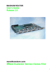
MAGNUM ROUTER
User’s Guide
Release 2.5
marathonstore.com
Where Customer Service Comes First
I
II
About this Guide
The Magnum Router User’s Guide describes how to install and configure the Magnum Router.
The Magnum Router is shipped with the Magnum GUI (graphical user interface) Manager, a
configuration and management software for Windows 95, 98, 2000, ME, XP and NT Workstation
4.0. The Magnum Router GUI Manager and all its features are detailed throughout this guide.
Additionally, this guide provides a brief introduction to Frame Relay and offers sample
configurations.
The Magnum Router User’s Guide is divided into two parts.
Part 1
Containing chapters 1 through 4, Part 1 describes the Magnum Router itself, and what’s
required to get the unit up and running.
Chapter 1 – Introduction and Overview
Chapter 2 - Before You Begin
Describes the Magnum Router and its features and specifications. Also explains
what you’ll need for installation.
Chapter 3 - Planning and Preparation
Suggests how you might plan the Magnum Router installation and configuration
in advance.
Chapter 4 - Installing the Hardware
Explains how to install the Magnum Router into a Marathon chassis.
Part 2
Chapters 5 through 10 comprise Part 2 of the User’s Guide. These chapters explain how to
install the software, and detail the many features of the Magnum Router GUI Manager.
Chapter 5 – Magnum Router Manager software Installation
Explains how to install the Magnum Router GUI Manager on your computer.
Chapter 6 – Logging onto a Magnum Router
Details how to access a Magnum Router from the Magnum Router Manager.
Chapter 7 – Magnum Router Manager GUI Manager
Describes the various functions of the Magnum Router Manager.
Chapter 8 – Magnum Router Manager Specialized Functions
Describes the functions that are exclusive to the Magnum Router Manager.
Chapter 9 – Sample Configurations
This chapter gives some real world examples of how to program the Magnum Router.
Chapter 10 – Troubleshooting
This chapter gives some common problems and solutions to problems that may occur
with the Magnum Router.
Chapter 11 – Cable Specifications
This chapter covers the cables used in connecting the Magnum Router to other devices.
Chapter 12 – Marathon Configuration
This chapter covers the steps required to program a Micom Marathon to function with
the Mangum Router.
III
Conventions Used in the Manual
Throughout this user manual, some information is outlined to inform of important items
regarding the section.
Text with this icon is to inform of cautionary information
Text with this icon is to inform of general information
Text with this icon is to inform of information that could cause errors if programmed or
used incorrectly
Text Bolded and Italicized text will denote a command button or a menu item in the Magnum
Router Manager.
IV
Table of Contents
CHAPTER 1: INTRODUCTION ................................................................1-1
About the Magnum Router ..........................................................................................1-1
CHAPTER 2: MAGNUM ROUTER FEATURES ......................................2-1
Magnum Router Specifications ..................................................................................2-2
Installation Requirements ...........................................................................................2-3
CHAPTER 3: PRE-INSTALLATION.........................................................3-1
Planning and Preparation............................................................................................3-1
Planning Worksheets...................................................................................................3-2
CHAPTER 4: INSTALLING THE HARDWARE .......................................4-1
CHAPTER 5: MAGNUM ROUTER MANAGER INSTALLATION ............5-1
Installing Manager Software .......................................................................................5-1
Upgrading the Magnum Router Manager...................................................................5-4
Starting the Magnum Router Manager .......................................................................5-4
First-Time Startup ..........................................................................................................5-5
CHAPTER 6: LOGGING ONTO A MAGNUM ROUTER ..........................6-1
Connecting to a Magnum Router................................................................................6-1
Console Cabling.............................................................................................................6-1
Telnet Cabling ................................................................................................................6-1
Marathon Matrix Cabling ................................................................................................6-2
Modem Connection Cabling...........................................................................................6-3
Magnum Router Login Screen ....................................................................................6-4
Login Methods..............................................................................................................6-4
Console Login ................................................................................................................6-5
Telnet .............................................................................................................................6-6
Micom Marathon Matrix..................................................................................................6-7
Modem ...........................................................................................................................6-9
Passwords ..................................................................................................................6-13
Login Messages .........................................................................................................6-14
Get Configuration.......................................................................................................6-14
Other Login Screen Options .....................................................................................6-15
Magnum Router Manager Terminal .............................................................................6-16
Magnum Router Manager Terminal Commands......................................................6-18
CHAPTER 7: MAGNUM ROUTER GUI MANAGER ................................7-1
Magnum Router Manager Main Screen ......................................................................7-2
Toolbar Buttons..............................................................................................................7-2
New Config Button .......................................................................................................7-3
Port Config Button .......................................................................................................7-4
WAN Config Button......................................................................................................7-7
Other WAN Config Buttons .........................................................................................7-9
V
Master WAN-IP Address ............................................................................................7-10
WAN-IP Route Map.....................................................................................................7-12
Advanced Routing .....................................................................................................7-14
RIP Version 1 Routing ...............................................................................................7-15
Ethernet Config Button..............................................................................................7-16
Micro-Band Voice Over IP .........................................................................................7-18
Save Configuration ....................................................................................................7-20
Send Configuration ....................................................................................................7-21
Reboot the Magnum Router ......................................................................................7-22
Menu Bar.....................................................................................................................7-24
Access Menu (ALT-A) ................................................................................................7-24
Configuration Menu (ALT-C) .....................................................................................7-27
Settings Menu (ALT-S)...............................................................................................7-31
System Menu (ALT-Y) ................................................................................................7-34
Statistics Menu (ALT-T) .............................................................................................7-48
Help Menu Item (ALT-H) ............................................................................................7-52
Exit Menu Item (ALT-X)..............................................................................................7-52
CHAPTER 8: MAGNUM ROUTER SPECIALIZED FUNCTIONS ............8-1
Virtual Routing .............................................................................................................8-1
Micro-Band Voice Over IP ...........................................................................................8-4
VoIP Types....................................................................................................................8-5
VoIP Type: Normal .......................................................................................................8-5
Dynamic Voice over IP (DVoIP)...................................................................................8-5
VoIP Type: “Host – Dynamic Mode”...........................................................................8-6
VoIP Type: “Remote – Dynamic Mode” .....................................................................8-6
RIP Routing...................................................................................................................8-7
CHAPTER 9: SAMPLE CONFIGURATIONS ...........................................9-1
Sample 1 - Dedicated Point to Point Network............................................................9-2
Sample 2 - Point to Point Public Frame Relay Network..........................................9-10
Sample 3 - Multi-Point Public Frame-Relay Network ..............................................9-16
Sample 4 - MicroBand VoIP.......................................................................................9-24
Sample 5 – Dynamic MicroBand VoIP ......................................................................9-32
Sample 6 – RIP Routing Point to Point Network .....................................................9-40
CHAPTER 10: MAGNUM ROUTER TROUBLESHOOTING .................10-1
LED Display Indicators ..............................................................................................10-1
Magnum Router Hardware Problems...........................................................................10-2
Magnum Router Power-up Self Test Problems .......................................................10-2
Frame Relay Link Does Not Come Up ......................................................................10-2
Frame Relay Link Performance Slow/Unreliable ...........................................10-3
Problems Connecting to the Manager......................................................................10-3
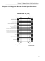
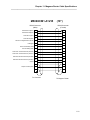
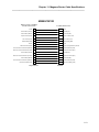
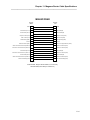
CHAPTER 11: MAGNUM ROUTER CABLE SPECIFICATIONS ..........11-1
CHAPTER 12: MARATHON PORT CONFIGURATION ........................12-1
Frame Relay Port Configuration Example ...............................................................12-1
Async Channel Configuration Example ...................................................................12-2
VI
CHAPTER 13: CONFIGURATION WORKSHEETS ...................................II
VII
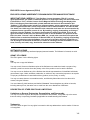
END USER License Agreement (EULA)
END USER LICENSE AGREEMENT FOR MAGNUM ROUTER MANAGER SOFTWARE
IMPORTANT READ CAREFULLY: This End-User License Agreement ("EULA") is a legal
agreement between you (either an individual person or a single legal entity, who will be referred to
in this EULA as "You") and the Licensor for the Magnum Router technology that displays this
EULA, including any associated media, printed materials and electronic documentation (the
"Software"). The Software also includes any software updates, add-on components, web services
and/or supplements that the Licensor may provide to You or make available to You after the date
You obtain Your initial copy of the Software to the extent that such items are not accompanied by
a separate license agreement or terms of use. By installing, copying, downloading, accessing or
otherwise using the Software, You agree to be bound by the terms of this EULA. If You do not
agree to the terms of this EULA, do not install, access or use the Software. For purposes of this
EULA, the term "Licensor" refers to Western NRG, Inc., except in the event that You acquired the
Software from an authorized distributor of Western NRG, Inc. By installing, copying, downloading,
accessing or otherwise using the Software, You agree to be bound by the terms of this EULA. If
You do not agree to the terms of this EULA, Licensor is unwilling to license the Software. In such
event, You may not install, copy, download or otherwise use the Software.
SOFTWARE LICENSE
The Software is protected by intellectual property laws and treaties. The Software is licensed, not sold.
GRANT OF LICENSE.
This EULA grants You the following rights:
Use.
You may use or copy this Software
You may not sell, license or distribute copies of the Software on a stand-alone basis or as part of any
collection, product or service where the primary value of the product or service are the Software.
You may not use or distribute any of the Software that include representations of identifiable individuals,
governments, logos, initials, emblems, trademarks, or entities for any commercial purposes or to express
or imply any endorsement or association with any product, service, entity, or activity.
You may not create obscene or scandalous works, as defined by federal law at the time the work is
created, using the Software.
You must indemnify, hold harmless, and defend “Licensor” from and against any claims or lawsuits,
including attorneys' fees, that arise from or result from the use or distribution of Software.
DESCRIPTION OF OTHER RIGHTS AND LIMITATIONS.
Limitations on Reverse Engineering, Decompilation, and Disassembly.
You may not reverse engineer, decompile, or disassemble the Software, except and only to the extent
that such activity is expressly permitted by applicable law notwithstanding this limitation.
Trademarks.
This EULA does not grant You any rights in connection with any trademarks or service marks of Licensor
or its suppliers.
VIII
No rental, leasing or commercial hosting.
You may not rent, lease, lend or provide commercial hosting services to third parties with the Software.
Support Services.
Licensor may provide You with support services related to the Software ("Support Services"). Use of
Support Services is governed by the policies and programs described in the user manual, in "online"
documentation, or in other materials from the support services provider. Any supplemental software code
provided to You as part of the Support Services are considered part of the Software and subject to the
terms and conditions of this EULA. You acknowledge and agree that Licensor may use technical
information You provide to Licensor as part of the Support Services for its business purposes, including
for product support and development. Licensor will not utilize such technical information in a form that
personally identifies You.
Termination.
Without prejudice to any other rights, Licensor or its suppliers may terminate this EULA if You fail to
comply with the terms and conditions of this EULA. In such event, You must destroy all copies of the
Software and all of its component parts.
INTELLECTUAL PROPERTY RIGHTS.
All title and intellectual property rights in and to the Software (including but not limited to any images,
photographs, animations, video, audio, music, text, and "applets" incorporated into the Software), the
accompanying printed materials, and any copies of the Software are owned by Licensor or its suppliers.
All title and intellectual property rights in and to the content that is not contained in the Software, but may
be accessed through use of the Software, is the property of the respective content owners and may be
protected by applicable copyright or other intellectual property laws and treaties. This EULA grants You
no rights to use such content. If this Software contains documentation that is provided only in electronic
form, you may print one copy of such electronic documentation. You may not copy the printed materials
accompanying the Software. All rights not specifically granted under this EULA are reserved by Licensor
and its suppliers.
U.S. GOVERNMENT LICENSE RIGHTS.
All Software provided to the U.S. Government pursuant to solicitations issued on or after December 1,
1995 is provided with the commercial license rights and restrictions described elsewhere herein. All
Software provided to the U.S. Government pursuant to solicitations issued prior to December 1, 1995 is
provided with RESTRICTED RIGHTS as provided for in FAR, 48 CFR 52.227-14 (JUNE 1987) or DFAR,
48 CFR 252.227-7013 (OCT 1988), as applicable.
EXPORT RESTRICTIONS.
You acknowledge that the Software is subject to U.S. export jurisdiction. You agree to comply with all
applicable international and national laws that apply to the Software, including the U.S. Export
Administration Regulations, as well as end-user, end-use and destination restrictions issued by U.S. and
other governments. For additional information.
APPLICABLE LAW.
If you acquired this Software in the United States, this EULA is governed by the laws of the State of
California.
If you acquired this Software in Canada, unless expressly prohibited by local law, this EULA is governed
by the laws in force in the Province of Ontario, Canada; and, in respect of any dispute which may arise
hereunder, you consent to the jurisdiction of the federal and provincial courts sitting in Toronto, Ontario. If
this Software was acquired outside the United States, then local law may apply.
DISCLAIMER OF WARRANTIES.
Western NRG, Inc. and its suppliers provide the Software and support services (if any) AS IS AND WITH
ALL FAULTS, and hereby disclaim all other warranties and conditions, either express, implied or
statutory, including, but not limited to, any (if any) implied warranties, duties or conditions of
merchantability, of fitness for a particular purpose, of accuracy or completeness of responses, of results,
of workmanlike effort, of lack of viruses, and of lack of negligence, all with regard to the Software, and the
provision of or failure to provide support services. ALSO, THERE IS NO WARRANTY OR CONDITION
OF TITLE, QUIET ENJOYMENT, QUIET POSSESSION, CORRESPONDENCE TO DESCRIPTION OR
IX
NON-INFRINGEMENT WITH REGARD TO THE Software.
EXCLUSION OF INCIDENTAL, CONSEQUENTIAL AND CERTAIN OTHER DAMAGES.
TO THE MAXIMUM EXTENT PERMITTED BY APPLICABLE LAW, IN NO EVENT SHALL WESTERN
NRG, INC. OR ITS SUPPLIERS BE LIABLE FOR ANY SPECIAL, INCIDENTAL, INDIRECT, OR
CONSEQUENTIAL DAMAGES WHATSOEVER (INCLUDING, BUT NOT LIMITED TO, DAMAGES FOR
LOSS OF PROFITS OR CONFIDENTIAL OR OTHER INFORMATION, FOR BUSINESS
INTERRUPTION, FOR PERSONAL INJURY, FOR LOSS OF PRIVACY, FOR FAILURE TO MEET ANY
DUTY INCLUDING OF GOOD FAITH OR OF REASONABLE CARE, FOR NEGLIGENCE, AND FOR
ANY OTHER PECUNIARY OR OTHER LOSS WHATSOEVER) ARISING OUT OF OR IN ANY WAY
RELATED TO THE USE OF OR INABILITY TO USE THE SOFTWARE, THE PROVISION OF OR
FAILURE TO PROVIDE SUPPORT SERVICES, OR OTHERWISE UNDER OR IN CONNECTION WITH
ANY PROVISION OF THIS EULA, EVEN IN THE EVENT OF THE FAULT, TORT (INCLUDING
NEGLIGENCE), STRICT LIABILITY, BREACH OF CONTRACT OR BREACH OF WARRANTY OF
WESTERN NRG, INC. OR ANY SUPPLIER, AND EVEN IF WESTERN NRG, INC. OR ANY SUPPLIER
HAS BEEN ADVISED OF THE POSSIBILITY OF SUCH DAMAGES.
LIMITATION OF LIABILITY AND REMEDIES.
Notwithstanding any damages that you might incur for any reason whatsoever (including, without
limitation, all damages referenced above and all direct or general damages), the entire liability of Western
NRG, Inc. and any of its suppliers under any provision of this EULA and your exclusive remedy for all of
the foregoing (except for any remedy of repair or replacement elected by Western NRG, Inc. with respect
to any breach of the Limited Warranty) shall be limited to the greater of the amount actually paid by you
for the Software or U.S.$5.00. The foregoing limitations, exclusions and disclaimers (including sections
described above) shall apply to the maximum extent permitted by applicable law, even if any remedy fails
its essential purpose.
ENTIRE AGREEMENT.
This EULA (including any addendum or amendment to this EULA which is included with the Software) is
the entire agreement between you and Western NRG, Inc. relating to the Software and the support
services (if any) and they supersede all prior or contemporaneous oral or written communications,
proposals and representations with respect to the Software or any other subject matter covered by this
EULA. To the extent the terms of any Western NRG, Inc. policies or programs for support services conflict
with the terms of this EULA, the terms of this EULA shall control.
X
Important Information – Please Read!!!
There have been several features removed in this version of the GUI manager; these are the
Display Port Statistics, Display Magnum Utilization, Remote Name Status and Port Status
Strobe functions in the Statistics Menu. Also, the DHCP server function has been removed.
It is important to note that if your existing Magnum Router configuration uses DHCP, DO NOT
USE THIS GUI MANAGER!
It does not support DHCP in any way, and if a configuration is sent, the existing DHCP
information will be deleted!!
Also note that upgrading a Magnum Router to revision E will also delete any DHCP information,
as revision E does not support DHCP.
XI
Chapter 1: Introduction
___________________________________________________________________
Chapter 1: Introduction
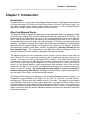
Introduction
Congratulations on your purchase of the Magnum Router Module. The Magnum Router Module
is a high performance IP Router and Frame Relay Switch. With the Frame Relay Switch, you
can create a private network, access a public frame relay service, or build an integrated hybrid
network with multiple carriers, offering public and private services.
About the Magnum Router
The Magnum Router is designed to enhance the existing Marathon data-voice integration family
of products by providing both increased WAN speeds and high performance IP Routing. The
Magnum Router is manufactured for use in a new or existing Marathon base unit to allow for
use of legacy serial data (both synchronous and asynchronous) as well as our ClearVoice
(compressed data-voice technology) and high performance IP Routing over public and private
networks. The Magnum operates over public Frame Relay networks as well as dedicated digital
data networks with speeds ranging from 56Kbps to full or fractional T1/E1 speeds. While this
guide discusses primarily Frame Relay networks, the Magnum is definitely intended for use
over dedicated links. The configuration of the WAN ports within the Magnum Router will
always be frame relay to take maximum advantage of this product’s design.
The Magnum Router can also encapsulate various protocols such as Micom serial data and
Clear Voice G.729 voice compression technology into IP packets for transport across any IP
network. This feature is known as Microband VoIP (or MVoIP). This means that the Magnum
may be used to transform your Marathon base unit into a serial data over IP and or compressed
voice over IP engine. By using the Magnum as a DOIP (data over IP) or VOIP (voice over IP)
engine, you can bundle Marathon legacy asynchronous data, Marathon Clear Voice and high
performance IP traffic all out the single 10/100Mpbs Ethernet interface for transport across your
private or public IP network. We cannot guarantee the quality of service over public IP
networks such as the public Internet. The Magnum Router module is specifically designed for
use over public Frame Relay and dedicated digital networks.
The Magnum Router module fits neatly into a new or existing Marathon base unit chassis. It is
intended for use in the Marathon 2K, 2Kplus, 3K, 5K Turbo, 5K Turbo Pro, 10K, 20K, 20K Pro
and Netrunner 75E base units with software revision 5.0 or later. The Magnum Router module
is not Marathon CCM (central control module) dependent. The Magnum Router module is both
a fully functional frame relay switch and high performance IP Router in one. It may function as a
standalone product by simply installing it into a Marathon chassis. However it is most popularly
used in conjunction with your existing Marathon network to preserve your data-voice integration
technology investment.
1-1
Chapter 1: Introduction
___________________________________________________________________
1-2
Chapter 2: Magnum Router Features
___________________________________________________________________
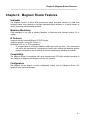
Chapter 2: Magnum Router Features
Scaleable
The Magnum Router’s 4 Serial WAN architecture allows enterprise networks to scale from
multipoint frame relay networks to multiple dedicated digital networks or a hybrid network of
carrier frame relay and dedicated networks.
Marathon Modularity
Field installable in any new or existing Marathon or Netrunner with software version 5.0 or
greater.
IP Features
Supports industry standard Ethernet TCP/IP Routing
Supports dynamic routing (RIP Version 1)
Microband VoIP / a.k.a. IP Encapsulation
IP encapsulation for all legacy Marathon traffic types such as Voice / Fax compressed
call traffic and synchronous / asynchronous legacy data, making the Marathon product
ready to traverse any new or existing IP network infrastructure including the Internet.
Compatibility
The Magnum Router is compatible with other manufacturers RFC1490 compliant products to
form Magnum to Magnum plus Magnum to brand (X) networks.
Configuration
The Magnum Router Module is easily configurable entirely from the Magnum Router GUI
(graphical user interface) Manager.
2-1
Chapter 2: Magnum Router Features
___________________________________________________________________
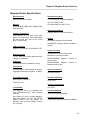
Magnum Router Specifications
Microprocessor
Standard Compliance
Motorola MPC-860T, 50Mhz
T1.617 ANNEX-D, ITU Q933-ANNEXA
ITU I.233, ANSI T1.606
Memory
64 MB SDRAM, 2MB FLASH, 16MB FLASH
DISK-ON-CHIP
ITU Q922-ANNEXA, ANSI T1.618
Management Options
Interface Connections
Windows based PC with GUI interface.
One male DB 25 V.35 (M1), Three male
DB25 V.35 WAN ports, One female DB25
RS-232 console port, One RJ 45 10/100
Base T Ethernet port.
Models
LAN Connection
Ethernet: auto-sensing 10/100 Base-T UTP.
WAN Connection
3 T1/E1 WAN ports support data rates from
56Kbps to 2.048 Mbps
IP Routing
Incorporates industry standard IP routing
M5000M/R1, Magnum Router Module
M5000M/SR1, Magnum Router Standalone
Version
Cables (included)
M5000C/CAT5E, Ethernet port cable.
M5000C/CP, console port cable.
M5000C/MODEM,
Modem Cable
Magnum
Console
to
M5000C/MATRIX, Magnum
Marathon Async Cable
Console
to
Performance
Forwarding Rate: 4000 packets per second.
Agency Compliance
Aggregate Sustained Throughput: 20 Mbps
ISO 9000 Certified
Frame Relay Support
Storage Temperature
DLCI’s/PVC’s: Unlimited
55 to +85 C
Frame Size: 2K
Operating Temperature
Compatibility
0 to +50 C
The Magnum Router is compatible with
other manufacturers RFC 1490 compliant
products.
Operating Humidity
Must reside in a new or existing Marathon
Base Unit Chassis: 2K, 2K+, 3K, NR75E,
5Kturbo, 5KTPro, 10K, 20K, 20Kpro. All
Marathon units must be software revision
5.0 or greater.
Operating Air Pressure
Up to 95% non-condensing
10,000 feet (3050 m) maximum altitude
2-2
Chapter 2: Magnum Router Features
___________________________________________________________________
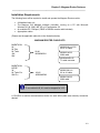
Installation Requirements
The following items will be required to install and operate the Magnum Router module:
•
•
•
•
A Marathon base unit.
The Magnum GUI Manager software (included), running on a PC with Microsoft
Windows 95, 98, 2000, ME, XP or NT workstation 4.0.
An available PC COM port. (DB9F to DB25M console cable included)
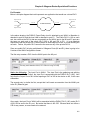
Appropriate cables:
(Please see the applicable cable kits in the illustration below)
MAGNUM ROUTER CABLE KITS
MARATHON:
2K
2K Plus
5K Turbo
10K
20K
M5000C/M1-A1V35
M1 to A1 cable
Kit #1
M5000M/RK1
M5000C/W123
WAN cable
M5000A/MR/V35
T1 rated converter
MARATHON:
NR75E
3K
5K Turbo Pro
20K Pro
Kit #2
M5000M/RK2
M5000C/M1-A1
M1 to A1 cable
M5000C/W123
WAN cable
To use cable kit #2, A1 must be strapped for V.35.
A CSU/DSU or similar communications device for each WAN (wide area network) connection
desired.
2-3
Chapter 2: Magnum Router Features
___________________________________________________________________
2-4
Chapter 3: Pre-Installation
___________________________________________________________________
Chapter 3: Pre-Installation
Planning and Preparation
Installing and configuring a Magnum Router module / Marathon system takes some up-front
planning. It is advisable to consider a number of configurations before deciding on the one that
is best for the specific application. Before actually connecting equipment to the Frame Relay or
dedicated digital network, it is suggested that the planning and preparation guidelines outlined
below be followed.
Planning the Magnum Router / Marathon Installation
It’s a good idea to create a drawing, mapping out the physical layout of the network. Include all
Magnum Router / Marathon units and all related CSU/DSU’s. Make sure to indicate the
following on the drawing:
•
•
•
•
•
Magnum Router WAN port orientation.
Such as DTE (connected to CSU/DSU or other DCE device) or DCE (directly
connected to additional FRAD’s or routers, bridges or other DTE devices).
The speed of each connection.
The path of each PVC, using dotted lines.
The DLCI numbers to be used for each end of each PVC, if your network is
public Frame Relay.
Available bandwidth for each PVC (CIR).
After successful installation of the Magnum Router / Marathon, retain this drawing for future
reference to aid in troubleshooting.
Planning the Configuration
The Magnum Router module is shipped with a default configuration. However, in most
instances, the default configuration will have to be changed to suit the installation’s specific
requirements.
The default configuration provides one DCE port (set for 128K, internal clocking, Frame Relay
lmi type: Annex D) on port M1 for connection to your new or existing Marathon base units A1
port via the appropriate M1-A1 external cable and one WAN DTE port (set for Frame Relay lmi
type Annex D) on port WAN1.
By default, ports WAN2 and WAN3 are disabled, and need to be enabled through the Magnum
Router Manager software.
The default IP address of the 10/100 Base-T E1 port is 10.1.100.250 with a subnet mask of
255.255.255.0 and the WAN IP address is 192.168.100.250 with a subnet of 255.255.255.0
The Magnum Router module also comes with a DB25 (RS-232) console port for connection to a
local PC communications port or dial modem for use with the Magnum Router GUI Manager
software (included). The console port default settings are 9600bps, no parity, 8 bits, 1 stop bit.
3-1
Chapter 3: Pre-Installation
___________________________________________________________________
The following items are also helpful (if not critical) for the planning phase to be completed:
•
•
•
•
•
Determine the Name of your Magnum Router
Determine the WAN Configuration (Port Settings)
Determine the Master WAN IP Address
Determine the WAN-IP Route Map information
Determine the Ethernet Port IP Address
Planning Worksheets
Located in chapter 13 is configuration planning worksheets to assist in the programming of the
Magnum Router.
3-2
Chapter 4: Installing the Hardware
___________________________________________________________________
Chapter 4: Installing the Hardware
Cable Kit Notes
The cable kit M5000M/RK-1 will work with any Marathon base unit, however if the Marathon
base unit that the Magnum Router is being installed into is a 75e, 3K, 5KT Pro or a 20K Pro;
then it is important that the jumper settings for the A1 port be set for RS-232 operation.
The cable kit M5000M/RK-2 is designed to work only with jumper selectable Marathon base
units (75e, 3K, 5KT Pro, and 20K Pro) as these units allow the A1 port to be changed from RS232 operation to V.35 operation. This cable kit will not work on Marathon units 2K, 2K Plus, 5K
Turbo, 10K and 20K.
Verify the Marathon base unit, and jumper position (if necessary) before installing the Magnum
Router.
Installing the Magnum Router Module into the Marathon base unit
Follow these steps to install the hardware.
1. Remove the power cord from the Marathon base unit. Remove the top cover. Remove
all of the necessary “blank” back plane dividers and internal module spacers (found at
the front of each module, nearest the LED’s).
2. Determine which level within the back plane the Magnum Router module is to be
installed. It is recommended that the Magnum Router be installed in the last module slot
or upper-most slot within the Marathon stack.
The Marathon CCM does not recognize the Magnum Router. This means that if
the Magnum is placed in the “B” slot, and the card above it is set for “B”, there will not
be a conflict. However, to eliminate confusion it is recommended that the Magnum
Router be placed in the top most level of the Marathon unit.
3. Install the module in the Marathon chassis like any other Marathon expansion module
paying close attention to the placement of the 2 “50 pin bus connectors” on the right side
of the module. Apply a reasonable amount of pressure over the bus connectors to
ensure the module is properly “seated” then re-install the necessary module spacers at
the front of the module. Using the screws removed from the step 1, fasten the Magnum
Router sheet metal back plane to the Marathon chassis and re-assemble the required
number of blank back plane dividers.
4. Re-install the Marathon base unit top cover and the 4 black screws to hold the top cover
in place.
4-1
Chapter 4: Installing the Hardware
___________________________________________________________________
5. Connect the appropriate M1 to A1 cable from the M1 port of the Magnum Router to the
A1 port of the Marathon base unit. Connect the appropriate WAN port cables to their
respective CSU/DSU’s Connect the manager console cable.
6. Power on the equipment.
This completes the hardware installation of the Magnum Router.
4-2
Chapter 5: Magnum Router Manager Installation
___________________________________________________________________
Chapter 5: Magnum Router Manager Installation
About the Manager Software
The Magnum Router GUI Manager is a configuration and management software for the
Magnum Router that runs on Windows. The Manager functions much the same as other
Windows programs.
The following will be required to install the software:
• The Magnum Router GUI Manager installation disk.
• PC with a hard drive that has at least 2 Mb of available space and a CD-ROM drive
• Windows 95, 98, 2000, ME, XP or NT workstation 4.0 PC operating system
If this is an upgrade from a previously installed version of the Magnum Router Manager,
follow the “Upgrading” steps below.
In some cases, the Setup program needs to do a pre-installation of certain support
programs, and then requires a reboot for these programs to take effect. If this occurs, after the
reboot, just restart the Setup program as outlined below.
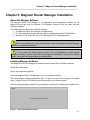
Installing Manager Software
The Magnum Router GUI Manager is installed much the same as any Windows software.
Follow these easy steps:
Exit all open Windows programs.
Insert the Magnum Router GUI Manager cd in your computers cd drive.
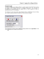
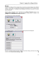
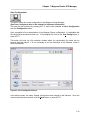
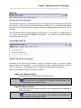
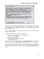
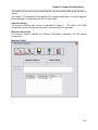
The Setup program should automatically start. If it does not, click on My Computer and select
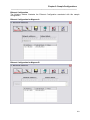
drive x: (where x is the CD-ROM drive) and double-click on the Setup program.
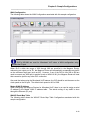
Once the Setup program is started, the pre-installation screen will be displayed as shown below:
Figure 1 - Setup Pre-Installation Screen
5-1
Chapter 5: Magnum Router Manager Installation
___________________________________________________________________
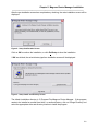
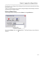
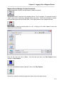
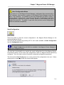
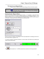
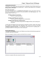
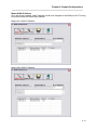
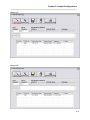
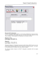
After the pre-installation screen has completed any checking, the main installation screen will be
displayed:
Figure 2 - Setup Confirmation Screen
Click on OK to continue the installation, or click Exit Setup to abort the installation.
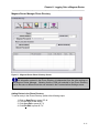
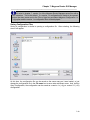
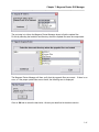
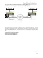
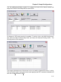
If OK was clicked, the select directory/perform installation screen will be displayed.
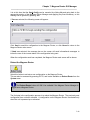
Figure 3 - Setup Install and Directory Screen
The default installation directory is C:\Program Files\Magnum Router Manager. If the program
needs to be installed on another hard drive, or another directory, click on Change Directory and
select the appropriate drive and directory location to install the program.
5-2
Chapter 5: Magnum Router Manager Installation
___________________________________________________________________
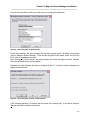
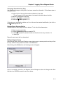
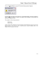
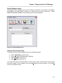
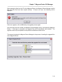
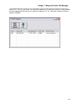
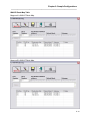
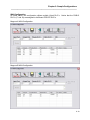
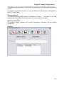
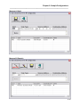
Click on the Setup button at the top of the screen to continue the installation.
Figure 4 - Setup Program, Program Group
During the installation, the setup program will request a program group. By default, the program
group is Magnum Router Manager. Enter another Program Group name, select one from the
list, or click on Continue to proceed.
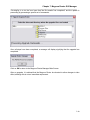
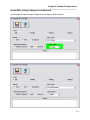
After clicking the Continue button, the setup program will install the Magnum Router Manager
files into the disk/directory selected earlier.
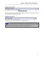
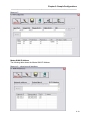
Depending on what software that may be installed on the PC, a Version Conflict message may
appear as shown below
Figure 5 - Setup Program, Version Conflict Screen
If this message appears, it is advised that the newer file is always kept. In the above example,
Yes was selected to keep the existing file.
5-3
Chapter 5: Magnum Router Manager Installation
___________________________________________________________________
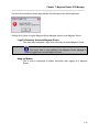
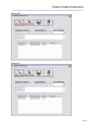
Once the installation process has completed, the setup program will display the following
message:
Figure 6 - Setup Program, Installation Complete Screen
Click on OK to return to the windows desktop.
Upgrading the Magnum Router Manager
If an earlier version of the Magnum Router manager has already been installed on the PC, it has
to be removed before installing the newer version. To uninstall the previous version of the
Magnum Router Manager, do these following steps:
•
•
•
•
•
•
Click on Start
Click on Settings
Click on Control Panel
Click on Add/Remove Programs
Click on the Magnum Router Manager entry
Select Remove Program
Once these steps have been completed, return to the installation steps in the first part of this
chapter.
Additional Folders
During the setup process, the program also creates some additional directories. One is the
DOCUMENT directory that contains a copy of this manual. Another is the SAMPLES directory
that contains the configuration samples located in this document.
Starting the Magnum Router Manager
To start the Magnum Router Manager, perform the following steps:
• Click Start
• Click Programs
• Click Magnum Router Manager
• Click the Magnum Router Manager icon
5-4
Chapter 5: Magnum Router Manager Installation
___________________________________________________________________
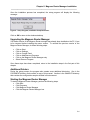
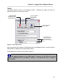
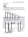
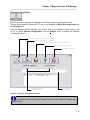
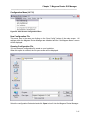
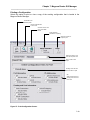
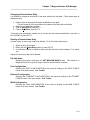
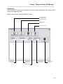
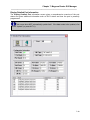
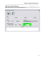
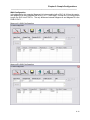
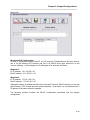
First-Time Startup
When the Magnum Router Manager first starts, it looks for setup information. If this is the first
time that you’re running the manager, the communication port settings screen will appear.
Save any configuration
changes to the Magnum
Router Manager
Exit this screen and
return to the Main
Screen
Enter Special Modem
Commands
Select the
communications port to
use for connection to the
Magnum Router
Figure 7 - Communication Port Setup Screen
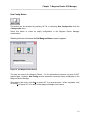
Select the PC’s communications port that is to be used to connect to the Magnum Router by
clicking on the Comm Port dropdown box. When you’ve completed that step, click on Save to
save this setting and then click on Exit to start the manager and get to the login screen.
If for some reason another communications port needs to be selected, clicking on the Settings
on the Main Screen menu bar, then select Communications Settings from the dropdown
menu. From the Comm Port Settings window select the appropriate communications port.
The Magnum Router console port baud rate is set at 9600bps from the factory and cannot be
changed.
This is the serial setup for communications from the PC to the Magnum Router console port and
does not have anything to do with a modem dial-up environment.
Once the initial setup has completed, the login screen will be displayed.
5-5
Chapter 5: Magnum Router Manager Installation
___________________________________________________________________
5-6
Chapter 6: Logging Onto a Magnum Router
___________________________________________________________________
Chapter 6: Logging Onto a Magnum Router
After the initial installation of the Magnum Router Manager software and its setup, the main
login screen is displayed. This screen is only displayed when the Magnum Router Manager is
first started or when the Login to a Magnum Router menu item is selected from the Access
menu.
This chapter covers the different methods of logging onto a Magnum Router and how to connect
equipment to allow the Magnum Router Manager to logon to the Magnum Router.
Connecting to a Magnum Router
As will be discussed in more detail later in this chapter, there are 4 methods of logging onto a
Magnum Router. Each method has a different cabling requirement – each is covered in this
section.
Console Cabling
To create a console login, first attach a straight-thru cable from a PC’s communications port to
the Magnum Router’s console port. Included with the Magnum Router is a DB-9 to DB-25
console cable labeled M5000C/CP. If the interface on the PC’s interface is a DB-25 and NOT a
DB-9, substitute the appropriate straight-thru cable.
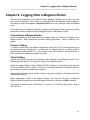
Telnet Cabling
A telnet login requires that there be an Ethernet cable attached to the Magnum Router’s E1 (or
Ethernet) port and that the PC can gain IP access to the Magnum Router.
Attach the supplied Ethernet cable (M5000C/CAT5E) Category-5 (or equivalent) cable from the
E1 port to an Ethernet hub or switch. If the PC is to be directly attached to the Magnum Router,
then an Ethernet crossover cable will be required.
A Successful connection can be visually verified, as the green link light on the Magnum Router’s
Ethernet port will be lit.
Before attempting to logon to the Magnum Router, verify that the PC that is running the
Magnum Router Manager can access the Magnum Router by performing a PING command.
The default IP address of the 10/100 Base-T E1 port is 10.1.100.250 with a subnet mask of
255.255.255.0.
6-1
Chapter 6: Logging Onto a Magnum Router
___________________________________________________________________
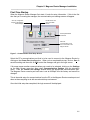
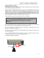
Marathon Matrix Cabling
It is possible to connect to a Magnum Router through a Marathon Async port either by direct
cable connection or by modem connection.
In order to perform a Marathon Matrix connection, there must be 2 available Async ports on the
Marathon base unit. Further, this will require 2 cables. If the connection is to be a direct
connection, then the M5000C/CP cable and the M5000C/MATRIX cables will be required. If the
connection is to be via a modem connection, then the M5000C/MODEM cable will connect the
modem to the Marathon Async port and the M5000C/MATRIX cable will be required to connect
the second Marathon Async port to the Magnum Router Console port.
This example assumes a direct connection from the PC to a Marathon.
It is very important that the Marathon Async channel that is to be
used is configured properly. Refer to chapter 12 for further
information.
First, attach the DB-9 to DB-25 console cable (included) from an available port of the Marathon
base unit to the PC that is running the Magnum Router Manager software.
Logon to the Marathon’s Command Facility menu and program a second Async port of the
Marathon unit as described in chapter 12.
Once the port has been programmed, logoff the Marathon and close the terminal session used
to access the Marathon.
Connect the M5000C/MATRIX cable (included) from the second programmed Async port (done
in the previous step) to the console port of the Magnum Router.
An example of cabling is shown below:
M5000C/MATRIX
M5000C/CP
PC
6-2
Chapter 6: Logging Onto a Magnum Router
___________________________________________________________________
Modem Connection Cabling
To connect a Modem to the Magnum Router, some preparation is required to ensure that the
Modem and the Magnum Router communicate properly.
The external modem must be a Hayes compatible (responds to the AT command set) in order
for a modem connection to be established.
First, attach a cable from a PC or a dumb terminal to the modem.
If using a PC, start a terminal program. Any terminal program such as Hyperterminal or the
terminal program of the Magnum Router Manager will perform the task.
Set the baud rate of the terminal program to 9600, the stop bits to 1, parity to none, and the bit
size to 8 (more commonly know as 9600,n,8,1).
Type in AT and press enter, the modem should respond with OK
Type AT&F&W and press Enter. The modem should respond with OK.
If it fails to respond, check the cable connection and check the modem to see if dipswitch
settings need to be changed. Consult the modem manual or vendor if necessary for assistance
Type the command string AT&D2&S1&C1&K0Q1E1S0=1&W and press Enter.
Below is a definition of the AT commands that is recommended:
&D2 Modem hangs up call if DTR drops
&S1 Modem drops DSR if carrier is lost
&C1 Modem drops DCD if carrier is lost
&K0 Modem flow control disabled _
Q1 Modem will not send result codes
E1 Modem will echo when in command state
S0=1 Modem will answer after 1 ring
&W Modem configuration is retained even if the modem loses power.
If your modem uses a different command for this function, you will need to substitute the
appropriate command in its place.
After completing the above steps, disconnect the PC or dumb terminal from the modem and
then connect the supplied DB-25 Male-to-Male cable (M5000C/MODEM) from the console port
of the Magnum Router to the external Modem.
This same command string will work if a Marathon Matrix connection is to be used in
conjunction with modem access to a Magnum Router, although a second modem cable will be
required to connect the Marathon base unit to the console port of the Magnum Router.
This completes the initial cabling of the Magnum Router. The next section covers the
actual login process.
6-3
Chapter 6: Logging Onto a Magnum Router
___________________________________________________________________
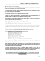
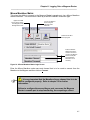
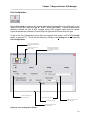
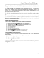
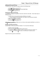
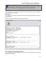
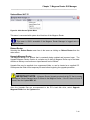
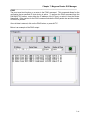
Magnum Router Login Screen
Bypass the LOGIN
Process and go directly
to the Magnum Router
Manager Main Screen
Connect to a Magnum
Router using the
selected LOGIN
METHOD
Start the TEXT ONLY
terminal program
De-Select this ONLY if
the Magnum Router's
access password has
been changed
Different METHODS to
login to a Magnum
Router
Input the new Magnum
Router access password
here IF it has been
changed
Figure 8 - Main Login Screen
The Magnum Router Login methods allow access to the Magnum Router via Console Port, Dial
Modem, Telnet or Marathon Matrix (by Marathon Node/Channel).
Logging into a Magnum Router is not required to input a configuration. However,
several functions of the Magnum Router Manager only function when logged in. Some of
these functions are:
Send Configuration
Reboot Router
The System menu option
The Statistics menu option
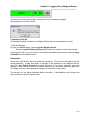
Begin the login process by selecting the desired Login Method. By default Console
connection is selected. To change to another method, click on the dropdown box next to the
Login Method label.
Login Methods
There are 4 different ways to connect to a Magnum Router using the Magnum Router Manager.
These Login Methods are covered below and in subsequent chapters through out the users
guide.
6-4
Chapter 6: Logging Onto a Magnum Router
___________________________________________________________________
Console Login
The default for logging onto a Magnum Router is a serial connection from the PC that is running
the Magnum Router Manager software to a Magnum Router card. The connection is
accomplished by connecting either the supplied DB-9 to DB-25 straight thru cable (or
equivalent) from the PC to the Magnum.
The settings for serial communication with a Magnum Router is 9600 Baud, 8 bits, No Parity
and 1 stop bit (commonly referred to as 9600,n,8,1) and cannot be changed.
As can be seen in the above screen, Console is already selected as the Login Method. Click
on the Connect button to begin the login process.
6-5
Chapter 6: Logging Onto a Magnum Router
___________________________________________________________________
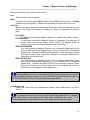
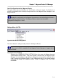
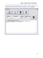
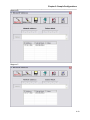
Telnet
This allows Ethernet access to the Magnum Router.
additional section to the main login screen.
Bypass the LOGIN
Process and go directly
to the Magnum Router
Manager Main Screen
Selecting this option will show an
Connect to a Magnum
Router using the
selected LOGIN
METHOD
Start the TEXT ONLY
terminal program
Enter EITHER the IP
address of the Magnum
Router, OR select a
name from the dropdown
box
Figure 9 - Telnet Login Screen
Login by typing in the IP address of the Ethernet port of the Magnum Router, or select a Router
Name and the IP address will be automatically filled in.
Router Names are covered in more detail in chapter 7.
The default IP address of the 10/100 Base-T E1 port is 10.1.100.250 with a subnet
mask of 255.255.255.0 and the WAN IP address is 192.168.100.250 with a subnet of
255.255.255.0
6-6
Chapter 6: Logging Onto a Magnum Router
___________________________________________________________________
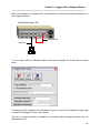
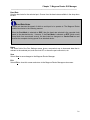
Micom Marathon Matrix
This gives the ability to connect to the Magnum Router’s console port via a Micom Marathon
matrix connection. This connection is done by a NODE/CHANNEL connection type.
Bypass the LOGIN
Process and go directly
to the Magnum Router
Manager Main Screen
Connect to a Magnum
Router using the
selected LOGIN
METHOD
Start the TEXT ONLY
terminal program
Enter the Marathon
NODE name and the
channel to be used to
connect to the Magnum
Router Console port,
and the Marathon
Password if one is
necessary
Figure 10 - Micom Marathon Matrix Login Screen
Enter the Micom Marathon node name and channel that is to be used to connect from the
Marathon to the Magnum and then click on Connect.
It is very important that the Marathon Async channel that is to be
used is configured properly. Refer to chapter 12 for further
information.
Failure to configure the second Async port can cause the Magnum
Router’s console port to stop functioning, thus requiring a reboot.
6-7
Chapter 6: Logging Onto a Magnum Router
___________________________________________________________________
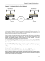
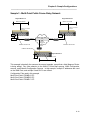
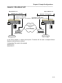
Below is an example of connecting a PC to the Marathon unit, and connecting the Marathon unit
to the Magnum Router.
Marathon Node Name: TOP
M5000C/MATRIX
M5000C/CP
PC
To use a login method of Marathon Matrix for the above example, fill in the fields as shown
below.
This causes the PC (attached to the Marathon A3 port) to connect to the Marathon A4 port that
is cabled to the Magnum Router’s console port.
This way, a single connection is capable of controlling both the Magnum Router and the
Marathon DVI unit.
6-8
Chapter 6: Logging Onto a Magnum Router
___________________________________________________________________
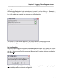
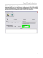
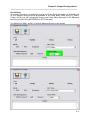
Modem
By default, the Magnum Router manager does not send any command strings to the attached
modem. In some cases, it is necessary to send special commands to the PC’s modem in order
to make it work properly. The Magnum Router Manager has the ability to send up to 5 of these
special commands.
Special modem commands can be accessed from the Modem Parameters button of the
Communications Settings screen. The communications settings screen is located in the
Settings menu, Communications Settings menu item.
The following screen will then be displayed.
Select Modem Params or press ALT-M and the following screen will be displayed:
Enter the commands required and click on Save to save these settings, and then click on Exit
to return to the Communications Settings screen.
6-9
Chapter 6: Logging Onto a Magnum Router
___________________________________________________________________
From this point on, the Magnum Router Manager will send the entered commands before dialing
the selected number.
If there is a modem change on the PC that is running the Magnum Router Manager, then these
commands may be changed or deleted.
Dialing to a Magnum Router
Start the Magnum Router Manager and select Modem in the Login Method box.
After selecting Modem, click on the Connect button. The Phone Directory screen will then be
displayed.
6-10
Chapter 6: Logging Onto a Magnum Router
___________________________________________________________________
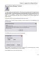
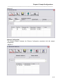
Magnum Router Manager Phone Directory
Figure 11 - Magnum Router Phone Directory Screen
All information entered in the Phone Directory is independent from the other settings of
the Magnum Router Manager. Meaning that the COM port selected in the Phone Directory
can be the same or different from the one selected in the Communications Settings screen.
Adding Entries in the Phone Directory
To add an entry in the Phone Directory, perform the following steps:
1. Click on New Entry or press ATL-N
2. Fill in the fields on the screen
3. Click Save Edit or press ALT-V
4. Click Exit Edit or press ALT-X
6-11
Chapter 6: Logging Onto a Magnum Router
___________________________________________________________________
Changing a Phone Directory Entry
It is possible to change an entry after it has been entered into the table. Follow these steps to
change an entry:
1. Double-Click on the entry that needs modification in the table
This will cause all of the entry data to be loaded in the fields above the table.
2. Make any modifications required
3. Click on Save Edit or press ALT-V
4. Clock on Exit Edit or press ALT-X
If this entry was selected by mistake and is not the one that needed modification, just click on
the Exit Edit or press ALT-X.
Deleting Phone Directory Entries
In some cases, an entry may need to be deleted. To do this, follow these steps:
1. Select an entry in the table.
2. Click the Delete Entry button or press ALT-D.
3. A verification question is asked to make sure that this is the entry to delete, if it
is, select yes.
Repeat for each entry that is to be deleted.
Dialing a Magnum Router
After entering data in the Phone Directory screen (make sure to save any entries so they will not
be lost), select the entry desired and click on the Dial button.
After clicking on the Dial button, the following screen will appear:
Upon a successful connection, the Magnum Router Manager’s status will change and reflect
that there is a MODEM connection as shown below.
6-12
Chapter 6: Logging Onto a Magnum Router
___________________________________________________________________
If an error occurs during the modem connection, an error message will appear.
One possible error is shown below.
Terminating a Dial Up
Terminating a modem connection to a Magnum Router can be accomplished in 2 ways.
(1) Exit the Manager.
(2) From the Access Menu, select Logoff the Magnum Router.
Selecting Logoff the Magnum Router will prompt if the modem is to be disconnected.
If the modem is left in an on-line state, it can be disconnected at a later time by selecting HangUp Modem from the Access menu.
Passwords
On the main login screen, there are places for passwords. The first is for the Magnum Router
access password. If there have been no changes to the passwords of the Magnum Router,
leave the Use Default Password checked, however, if the access password has been
changed, remove the check next to the default password box, and enter the access password.
The Magnum Router access password change is covered later in this section.
The second is for the Micom Marathon Matrix connection. If the Marathon that is being used
has no password, leave this space blank.
6-13
Chapter 6: Logging Onto a Magnum Router
___________________________________________________________________
Login Messages
After selecting the desired login method, select connect by either clicking on Connect, or
pressing ALT-C. If Modem was selected, the dialing directory will appear (see above), but if
any other method was selected, the status screen will be displayed.
This screen is for informational purposes, just to show the status of the login process.
Once the basic login process has completed, the following question will be asked:
Get Configuration
After a successful login, the Magnum Router Manager will inquire about getting the current
configuration from the Magnum Router that has just been logged into. If this is new installation,
click No. If the configuration of the connected Magnum Router requires viewing or modification,
then select Yes
If Yes was selected, the following screen will appear, reporting that the manager is getting the
connected Magnum Router’s stored configuration.
6-14
Chapter 6: Logging Onto a Magnum Router
___________________________________________________________________
Other Login Screen Options
There are 2 other buttons on the login screen.
Select this button by either clicking on it, or pressing ALT-D. This will bypass the login process
and will then show the Magnum Router Manager main screen.
6-15
Chapter 6: Logging Onto a Magnum Router
___________________________________________________________________
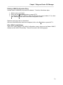
Magnum Router Manager Terminal
This option opens a text-based terminal. This can be used to program optional equipment (such
as a Micom Marathon) without having to exit the Magnum Router Manager. It is NOT a VT100
terminal emulator. This means that special control characters are not recognized and will be
displayed. As an example, it could be used to access a Micom Marathon to check the unit
status. The terminal program will ONLY work if the Manager IS NOT currently logged onto a
Magnum Router.
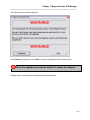
The terminal can only be accessed through the main login screen.
Clicking on the “Terminal” button will display a cursory warning as to the capabilities of the
terminal program.
Click OK and the terminal mode screen will be displayed.
Select Serial if the connection to the device is using the PC’s communications port, or select
Telnet and enter a Host IP address to connect remotely.
Select Cancel to return to the main login screen.
6-16
Chapter 6: Logging Onto a Magnum Router
___________________________________________________________________
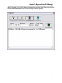
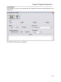
Selecting Activate Terminal will display the Magnum Router Manager terminal screen.
Figure 12 - Magnum Router Manager Terminal Screen
The terminal program has an internal scroll back buffer of 4000 bytes, the ability to capture
incoming data to a file and the ability to send a “break” sequence to a device.
It does NOT include any file transfer capabilities.
6-17
Chapter 6: Logging Onto a Magnum Router
___________________________________________________________________
Magnum Router Manager Terminal Commands
As seen in the above screen, the terminal has 3 basic commands:
This sends a “break” sequence to the attached device. As an example, it is required to send 3
“break” sequences to terminate a Marathon Matrix connection. Each time this button is clicked,
the terminal program will show “Break Sent” in the display when it has completed the task.
This is used for capturing incoming data to a file. Clicking on the “Start Capture” button will
display the file save screen.
Enter the file name and click on Save. Once this has been done, the Start Capture button
changes to Stop Capture.
Once the desired data has been captured, click on the Stop Capture.
Select this to close the terminal program and return to the main login screen.
6-18
Chapter 7: Magnum Router GUI Manager
___________________________________________________________________
Chapter 7: Magnum Router GUI Manager
The Manager User Interface
The Magnum Router GUI Manager uses a graphical user interface common to most Windows
programs. Movement around the manager is done by either clicking the button or menu item,
using shortcut keys (as shown by an underscore under a letter or a menu or button), or using
the tab key.
Selected buttons change text color from black to red
Throughout the Magnum Router Manager, there are several shortcut keys that have been kept
constant, these are:
ALT-V = is used to save changes to edited fields, or save an entire screen of data.
ALT-X = is used to exit editing, or exit a screen to the previous screen
ALT-N = is used to create a new configuration or entry in a screen
ALT-D = is used for deletion of data from a screen
Important Note: Any data that is entered into the Magnum Router
Manager is not sent to any Magnum Router until the Send Config button is
selected.
7-1
Chapter 7: Magnum Router GUI Manager
___________________________________________________________________
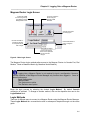
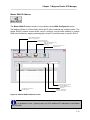
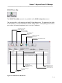
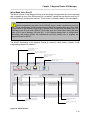
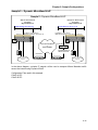
Magnum Router Manager Main Screen
Menu Bar
Toolbar
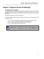
Magnum Name.
Display's the name assigned to the
Magnum Router that the Manager is
currently logged into
Remote Access.
This ONLY shows when a Magnum
Router is being remotely accessed.
Connection Type.
Display's how the Magnum Router
Manager is connected to a Magnum
Router
Transmit Data.
Flashes RED when data is sent.
Receive Data.
Flashes RED when data is received
Connection Status
Green Up Arrow = Connected to a Magnum
Router
RED Down Arrow= Not Connected
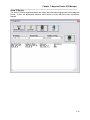
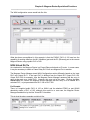
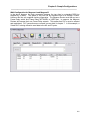
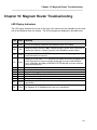
Figure 13 - Magnum Manager Main Screen
The Magnum Router Manager screen is broken into 3 sections. The Menu Bar, the Toolbar and
the Status bar. Each of these sections are covered in detail throughout this chapter.
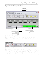
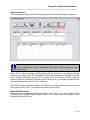
Toolbar Buttons
Figure 14 - Main Screen Toolbar
The Toolbar buttons are displayed below the Menu Bar and consist of seven command buttons,
which correspond to the seven primary steps to program the Magnum Router. Each of these
buttons can be accessed by clicking on them, using their shortcut key or by selecting the option
in the appropriate menu item (as described above).
7-2
Chapter 7: Magnum Router GUI Manager
___________________________________________________________________
New Config Button
This button can be accessed by pressing ALT-N, or selecting New Configuration from the
Configuration menu.
Select this button to create an empty configuration in the Magnum Router Manager
customization.
Selecting this item will cause the Set Mangum Name screen to appear
Figure 15 - Set Magnum Name Screen
This sets the name of the Magnum Router. It is for informational purposes only and IS NOT
required data. However, New Config must be selected to create an empty configuration in the
Magnum Router Manager.
After entering the name, click Save or press ALT-V to save the name. When completed, click
on the Exit, or press ALT-X to return to the Magnum Manager main screen.
7-3
Chapter 7: Magnum Router GUI Manager
___________________________________________________________________
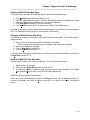
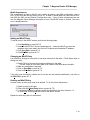
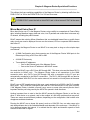
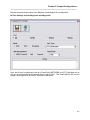
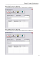
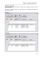
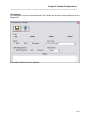
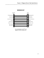
Port Config Button
Select Port Config to configure the physical and logical characteristics of the WAN ports of the
Magnum Router (the WAN ports are M1, WAN1, WAN2 and WAN3). Physical characteristics
determine whether the port is DTE (accepts clock), DCE (supplies clock) and port speed.
Logical characteristics include the Frame Relay LMI type and the Frame Relay link type.
To get to the Port Configuration screen from the manager main screen, click the Port Config
button, or press ALT-P. This is also accessible by clicking on the Settings menu and selecting
Port Configuration.
S ave an y c on f ig u ration
C h an g es th at h ave b een
m ad e
E xit th is s c reen to th e
M ain S c reen
C h oos e th e M O D E of
th e s elec ted p ort
S elec t w h ic h W A N p ort
to c on fig u re b y c lic kin g
in th e c irc le n ext to th e
p ort n am e
S elec t th e p ort's s p eed
S elec t th e L M I T yp e
S elec t th e p ort's fram e
relay lin k typ e
A d d N O T E S to as s is t in
d oc u m en tation
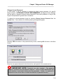
Figure 16 - Port Configuration Screen
7-4
Chapter 7: Magnum Router GUI Manager
___________________________________________________________________
Below is a description of the fields on this screen:
Port
Selects the port to be configured.
Mode
Configures the port as physical DCE (supplies clock), DTE (receives clock), or Disable
(disables the port altogether). Disable is recommended if the port will not be in use.
Link Type
Specifies the logical interface for the Magnum Router port. Select from the options in the
list box. (Link Types are illustrated in Chapter 8). Below is a description of each link
type.
FR_PUBLIC
Is used when connecting a Magnum WAN port to a public Frame Relay network.
FR_DEDICATED
Is used when connecting a Magnum Router to a Marathon or another type of
Frame Relay Access Device (bridge, Router, FRAD). The Magnum WAN port
functions as a frame relay network port when using this setting.
DEDICATED-MASTER
Use when connecting Magnum Router’s over a dedicated digital data circuits
(such as 56K point to point leased lines or T1/E1 or fractional T1/E1 dedicated
leased lines). Selecting the DEDICATED-MASTER causes the Magnum Router
WAN port to function as a Frame Relay Network Port (supplying LMI and DLCI
information to the remote site).
DEDICATED-SLAVE
Use when connecting Magnum Router’s over a dedicated digital data circuits
(such as 56K point-to-point leased lines or T1/E1 or fractional T1/E1 dedicated
leased lines). Selecting the DEDICATED-SLAVE causes the Magnum Router
WAN port to function as a Frame Relay User Port (accepting LMI and DLCI
information from the Magnum Router Master unit).
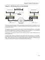
If installing Magnum Routers on a dedicated (or DDS) circuit, it is important to note that
one of the Magnum Routers needs to be set as DEDICATED_MASTER and the other as
DEDICATED_SLAVE in order to create a private frame-relay network.
Link Management
Defines the Frame Relay Link Management protocol, either ANSI/Annex D or LMI or
Annex A.
Link management protocol is used in all public Frame Relay applications. The Magnum
Router WAN port(s) must match the lmi type being provided by the carrier. It is
recommended that you request ANSI /Annex_ D for all your frame relay connections.
7-5
Chapter 7: Magnum Router GUI Manager
___________________________________________________________________
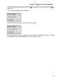
Baud Rate
Sets the baud rate for the selected port. Choose from the baud rates available in the drop down
list box.
Baud Rate Notes
A baud rate denotes the speed of which a serial port is to operate at. The Magnum Router
handles baud rates in the following manner:
When the Port Mode is selected as DCE, then the baud rate selected is the reported clock
speed to the attached device. However, if the Port Mode is selected as DTE (which would
accept clock from an external source), the baud rate box changes to a Carrier Rate box and
denotes the accepted clocking speed of an attached device.
Notes
The notes field of the Port Settings screen gives a convenient way to document data that is
relevant to the selected port, such as circuit ID, or where the port connects to, etc.
Save
Select Save to save changes to the Magnum Router Manager.
Exit
Select Exit to close this screen and return to the Magnum Router Manager main screen.
7-6
Chapter 7: Magnum Router GUI Manager
___________________________________________________________________
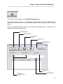
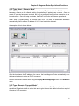
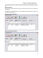
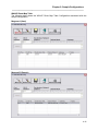
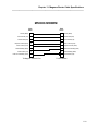
WAN Config Button
Click the WAN Config button on the Magnum Router Manager main screen, press ALT-W, or
select WAN Configuration from the Settings menu to access the WAN Configuration screen.
In a frame relay environment, end-points are connected together via the use of PVC’s
(Permanent Virtual Circuits). The WAN Configuration screen is where these PVC connections
are created in the Magnum Router.
Add a NEW WAN entry
into the configuration
Delete a WAN entry
from the configuration
Save changes to the
Magnum Router
Manager
Exit this screen and
return to the Main
Screen
Add an IP address to the
WAN port of the
Magnum Router
Add IP routing
information for the WAN
DLCI number fields
Add documentation
notes for each entry
Select the Frame Relay
OUTPUT Port
Whether to treat this
connection a as
multiplexed DLCI
(Virtual) or as a passthru DLCI
The Commited
Information Rate of the
Frame Relay Circuit
Select the Frame Relay
INPUT Port
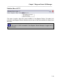
Figure 17 - WAN Configuration Screen
7-7
Chapter 7: Magnum Router GUI Manager
___________________________________________________________________
The Input and Output port fields of the WAN Configuration screen define the physical ports of
the Magnum Router.
The Private and Public DLCI fields define the DLCI end-points of the PVC. A PUBLIC DLCI
would (in most cases) be the DLCI that is being supplied by the Frame Relay provider. The
PRIVATE DLCI is (under normal circumstances) an internal number that is used ONLY by the
devices attached to the Magnum Router.
The CIR is the Committed Information Rate of the circuit; the Frame Relay provider supplies
this.
The Non Virtual DLCI checkbox is a special configuration command that is clarified in chapter 8.
Notes allows for a note regarding the entry. Each entry can have it’s own note, and each note
can be up to 1,024 characters in length.
Adding a WAN Configuration Entry
To add an entry in the Master WAN-IP screen, perform the following steps:
1.
2.
3.
4.
5.
6.
7.
8.
9.
Begin by clicking on the New Entry button, or by pressing ALT-N
Select the Input Port from those available in the drop down list box.
Select the Output Port from the dropdown box.
Enter the Private DLCI
Enter the Public DLCI
Enter the CIR for this connection
Select Non Virtual DLCI if required.
Click on the Save Edit, or press ALT-V to save this entry.
Click on the Exit Edit, or press ALT-X to end this entry.
Changing a WAN Configuration Entry
It is possible to change an entry after it has been entered into the table. Follow these steps to
change an entry:
1.
2.
3.
4.
Double-Click on the entry that needs modification in the table
Make any modifications required
Click on Save Edit or press ALT-V
Click on Exit Edit or press ALT-X
If this entry was selected by mistake and is not the one that needed modification, just click on
the Exit Edit or press ALT-X.
7-8
Chapter 7: Magnum Router GUI Manager
___________________________________________________________________
Deleting a WAN Configuration Entry
In some cases, a WAN entry may need to be deleted. To do this, follow these steps:
1. Select an entry in the table.
2. Either click the Delete Entry button or press ALT-D.
3. A verification question is asked to make sure that this is the entry to delete, if it is, select
Yes. Selecting No will return to the WAN Configuration screen.
Repeat for each entry that is to be deleted.
Once all of the WAN entries have been completed, click on the Save button or press ALT-V.
Other WAN Config Buttons
There are 2 other options in the WAN Configuration screen; these are the Master WAN-IP
Address and the WAN-IP Route Map. These are covered in the following pages.
7-9
Chapter 7: Magnum Router GUI Manager
___________________________________________________________________
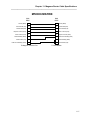
Master WAN-IP Address
The Master WAN-IP address screen is only available via the WAN Configuration screen.
The Magnum Router is a Frame Relay switch and IP router combined into a single product. The
Master WAN-IP address screen allows users to configure a single WAN interface or multiple
WAN sub-interfaces by mapping and assigning a unique IP network number to specific DLCI’s.
Add a NEW W AN entry
into the configuration
Delete a W AN entry
from the configuration
Save any changes to the
Magnum Router
Manager
Exit this screen to the
Main Screen
DLCI Number assigned
to the IP address
IP Address to assign to
the W AN Port
Subnet Mask of the IP
Address
Add documentation
notes for each entry
Figure 18 - Master WAN IP Address Screen
It is possible to have 1 primary and up to 253 additional IP addresses in the Master
WAN-IP table.
7-10
Chapter 7: Magnum Router GUI Manager
___________________________________________________________________
Adding a Master WAN-IP Address Entry
To add an entry in the Master WAN-IP screen, perform the following steps:
1.
2.
3.
4.
Click on New Entry or press ATL-N
Type in the Network Address, Subnet Mask and DLCI
Click Save Edit or press ALT-V
Click Exit Edit or press ALT-X
If you have more than one remote site to connect to, program a unique IP network number for
each WAN sub-interface and map them to their respective unique DLCI number. (refer to
chapter 9, sample 3)
Changing a Master WAN-IP Address Entry
It is possible to change an entry after it has been entered into the table. Follow these steps to
change an entry:
1.
2.
3.
4.
Double-Click on the entry that needs modification in the table
Make any modifications required
Click on Save Edit or press ALT-V
Click on Exit Edit or press ALT-X
If this entry was selected by mistake and is not the one that needed modification, just click on
the Exit Edit or press ALT-X.
Deleting a Master WAN-IP Entry
In some cases, an entry may need to be deleted. To do this, follow these steps:
1. Select an entry in the table.
2. Either click the Delete Entry button or press ALT-D.
3. A verification question is asked to make sure that this is the entry to delete, if it is, select
Yes. Selecting No will return to the Master WAN-IP Address screen.
Repeat for each entry that is to be deleted.
7-11
Chapter 7: Magnum Router GUI Manager
___________________________________________________________________
WAN-IP Route Map
The WAN IP Route Map screen is only available via the WAN Configuration screen.
The next step will be to fill data into the WAN-IP Route Map screen. The purpose of the WANIP Route Map is to set the destination network address with its corresponding DLCI number,
port number and associated gateway (a.k.a. next hop IP address).
Add a NEW W AN entry
into the configuration
Delete a W AN entry
from the configuration
Save changes to the
Magnum Router
Manager
Exit this screen to the
Main Screen
Enter additional routes
Destination IP
NETW ORK address
and subnet mask of the
remote site
Address of the "Next
Hop" router
Add documentation
notes for each entry
DLCI Number assigned
to this route
Port number assigned
for this route
Figure 19 - WAN-IP Route Map Screen
7-12
Chapter 7: Magnum Router GUI Manager
___________________________________________________________________
Adding a WAN IP Route Map Entry
To add an entry in the WAN IP Route Map screen, perform the following steps:
1. Click New Entry and select the Ethernet 1 port
2. Enter the appropriate private DLCI number, destination network IP address and subnet
mask and corresponding gateway (a.k.a. next hop IP address)
3. Click Save Edit or press ALT-V to save the entry
4. Click Exit Edit or press ALT-X to return to the WAN IP Route Map screen.
All entries in the WAN IP Route Map are automatically written to the Advanced Routing table as
well. The Advanced Routing section is covered later in this section.
Changing a WAN-IP Route Map Entry
It is possible to change an entry after it has been entered into the table. Follow these steps to
change an entry:
1. Double-Click on the entry that needs modification in the table
This will cause all of the entry data to be loaded in the fields above the table.
2. Make any modifications required
3. Click on Save Edit or press ALT-V
4. Click on Exit Edit or press ALT-X
If this entry was selected by mistake and is not the one that needed modification, just click on
the Exit Edit or press ALT-X.
Deleting a WAN-IP Route Map Entry
In some cases, an entry may need to be deleted. To do this, follow these steps:
1. Select an entry in the table.
2. Either click the Delete Entry button or press ALT-D.
3. A verification question is asked to make sure that this is the entry to delete, if it is, select
Yes. Selecting No will return to the WAN-IP Route Map screen.
Repeat for each entry that is to be deleted.
If there is no need to add additional routes to the Magnum Router, click on Save or press ALT-V
to save any changes, then click on Exit, or press ALT-X to return to the WAN Configuration
screen.
7-13
Chapter 7: Magnum Router GUI Manager
___________________________________________________________________
Advanced Routing
This function is only available via the WAN-IP Route Map screen.
The Advanced Routing section of the Magnum Router Manager allows for additional static
routes to be entered. Such routes may include a default route to another router for Internet
access.
Click on the Advanced Routing button of the WAN IP Route Map screen, or press ALT-A to
display the Advanced Routing screen.
Add a NEW W AN entry
into the configuration
Delete a W AN entry
from the configuration
Save changes to the
Magnum Router
Manager
Exit this screen to the
Main Screen
Enable or Disable
Dynamic Routing (RIP
Version 1)
Address of the "Next
Hop" router
Destination IP
NETW ORK address
and subnet mask of the
remote site
Add documentation
notes for each entry
7-14
Chapter 7: Magnum Router GUI Manager
___________________________________________________________________
Figure 20 - Advanced Routing Screen
Adding an Advanced Routing Entry
To add an entry in the WAN IP Route Map screen, perform the following steps:
1. Click New Entry or press ALT-N
2. Enter data in the IP Address, Subnet Mask, and Gateway Address fields
3. Click Save Edit or press ALT-V to save the entry
4. Click Exit Edit or press ALT-X to return to the WAN IP Route Map screen.
Changing an Advanced Routing Entry
It is possible to change an entry after it has been entered into the table. Follow these steps to
change an entry:
1. Double-Click on the entry that needs modification in the table
This will cause all of the entry data to be loaded in the fields above the table.
2. Make any modifications required
3. Click on Save Edit or press ALT-V
4. Click on Exit Edit or press ALT-X
If this entry was selected by mistake and is not the one that needed modification, just click on
the Exit Edit or press ALT-X.
Deleting an Advanced Routing Entry
In some cases, an entry may need to be deleted. To do this, follow these steps:
1. Select an entry in the table.
2. Either click the Delete Entry button or press ALT-D.
3. A verification question is asked to make sure that this is the entry to delete, if it
is, select Yes. Selecting No will return to the Advanced Routing screen.
Repeat for each entry that is to be deleted.
Once the additional routes have been added, click on Save or press ALT-V to save any
changes, then click on Exit, or press ALT-X to return to the WAN-IP Route Map screen.
RIP Version 1 Routing
Enable RIP routing by clicking on the box next to Enable RIP Version 1 Routing. To disable
RIP routing, remove the check in the box.
The Magnum Router implements the RIP routing protocol in a “hybrid” fashion. It is covered in
more detail in chapter 8.
7-15
Chapter 7: Magnum Router GUI Manager
___________________________________________________________________
Ethernet Config Button
Select this button to program IP addresses on the Ethernet port of the Magnum Router.
This can be accessed by pressing ALT-E, and is also available as Ethernet Configuration from
the Settings menu.
From the Magnum Router Manager main screen, click on the Ethernet Config button, press
ALT-E, or select Ethernet Configuration from the Settings menu to display the Ethernet
Configuration screen.
Add a N EW
E t h e r n e t e n t r y in t o t h e C o n f ig u r a t io n
D e le t e a n e n t r y f r o m t h e c o n f ig u r a t io n
S a v e a n y c h a n g e s to th e M a g n u m R o u te r M a n a g e r
E x it t h is s c r e e n t o t h e M a in S c r e e n
E n t e r M V o I P I n f o r m a t io n
IP A d d re s s a n d s u b n e t
m a s k f o r t h is e n t r y
D o c u m e n t a t io n
r e g a r d in g t h is e n t r y
Figure 21 - Ethernet Configuration Screen
It is possible to have 1 primary IP address and up to 253 additional IP addresses
on the E1 port.
7-16
Chapter 7: Magnum Router GUI Manager
___________________________________________________________________
Adding an Ethernet IP Entry
To add an entry in the Ethernet IP screen, perform the following steps:
1. Click New Entry or press ALT-N
2. Enter data in the IP Address and Subnet Mask fields
3. Click Save Edit or press ALT-V
4. Click Exit Edit or press ALT-X
Changing an Ethernet IP Entry
It is possible to change an entry after it has been entered into the table. Follow these steps to
change an entry:
1. Double-Click on the entry that needs modification in the table
This will cause all of the entry data to be loaded in the fields above the table.
2. Make any modifications required
3. Click on Save Edit or press ALT-V
4. Clock on Exit Edit or press ALT-X
If this entry was selected by mistake and is not the one that needed modification, just click on
the Exit Edit or press ALT-X.
Deleting an Ethernet IP Entry
In some cases, an entry may need to be deleted. To do this, follow these steps:
1. Select an entry in the table.
2. Either click the Delete Entry button or press ALT-D.
3. A verification question is asked to make sure that this is the entry to delete, if it
is, select Yes. Selecting No will return to the Ethernet IP address screen.
Repeat for each entry that is to be deleted.
7-17
Chapter 7: Magnum Router GUI Manager
___________________________________________________________________
Micro-Band Voice Over IP
The MVoIP function of the Magnum Router gives the ability to encapsulate any frame relay data
that is supplied on any of the WAN ports into a routable IP packet that can be sent over any IP
LAN environment (including the Internet). This function is covered in detail in the next chapter.
Before programming any data into the MVoIP screen, certain requirements must be
met. These requirements include having to have a WAN Configuration Map entry (See WAN
Configuration in this chapter) using a DLCI between 900 and 989 that is mapped from any
WAN port to the E1 port, and a WAN-IP Route Map entry for Frame Relay routing that also
uses a DLCI that is between 900 and 989. In the Sample chapter there is configuration
information that further defines the requirements and just exactly how to program the
Magnum Router for MVoIP.
The MVoIP functionality of the Magnum Router is covered in more detail in chapter 8 with
programming samples in chapter 9.
A d d a N E W M V o IP
e n t r y in t o t h e
c o n f ig u r a t io n
D e le t e a n M V o I P e n t r y
f r o m t h e c o n f ig u r a t io n
S a v e a n y c h a n g e s to th e
M a g n u m R o u te r
M an ag er
E x it t h is s c r e e n t o t h e
M a in S c r e e n
M V o IP T y p e
M V o I P D L C I ( E n t e r e d in
t h e W A N C o n f ig u r a t io n
s c ree n )
S o u r c e M V o IP A d d r e s s
D e s t in a t io n M V o I P
A d d re s s
N o t e s r e g a r d in g t h is
e n tr y
Figure 22 - MVoIP Screen
7-18
Chapter 7: Magnum Router GUI Manager
___________________________________________________________________
MVoIP Requirements
The requirements to add an MVoIP entry include an entry in the WAN configuration using a
DLCI of 900 thru 989 and an output port of E1; a WAN IP Route Map entry that uses a DLCI
from 900 thru 989, and an Ethernet Configuration entry. If any of these requirements are not
met, the Magnum Router Manager will report an error if the MVoIP button is clicked. One such
error is displayed below:
Adding an MVoIP Entry
To add an entry in the MVoIP screen, perform the following steps:
1. Click New Entry or press ALT-N
2. Select the MVoIP DLCI from the dropdown box, select the MVoIP type from the
dropdown box, enter data in the Source IP Address and destination IP address
3. Click Save Edit or press ALT-V
4. Click Exit Edit or press ALT-X
Changing an MVoIP Entry
It is possible to change an entry after it has been entered into the table. Follow these steps to
change an entry:
1. Double-Click on the entry that needs modification in the table
This will cause all of the entry data to be loaded in the fields above the table.
2. Make any modifications required
3. Click on Save Edit or press ALT-V
4. Clock on Exit Edit or press ALT-X
If this entry was selected by mistake and is not the one that needed modification, just click on
the Exit Edit or press ALT-X.
Deleting an MVoIP Entry
In some cases, an entry may need to be deleted. To do this, follow these steps:
1. Select an entry in the table.
2. Either click the Delete Entry button or press ALT-D.
3. A verification question is asked to make sure that this is the entry to delete, if it
is, select Yes. Selecting No will return to the MVoIP screen.
Repeat for each entry that is to be deleted.
7-19
Chapter 7: Magnum Router GUI Manager
___________________________________________________________________
Save Configuration
This option saves the current configuration in the Magnum Router Manager.
(See Save Config notes later in this chapter for important information)
This can also be accessed by pressing ALT-V, and is also available as Save Configuration
from the Configuration menu.
Upon completion of the customization of the Magnum Router configuration, it is advisable that
the configuration be saved for later use. To accomplish this, click on the Save Config button, or
press ALT-V.
This action will bring up a file selection window where the configuration file name can be
entered, and then saved. It is not necessary to put any extension on the filename, which is
done automatically.
Figure 23 - Save Configuration Screen
In the above screen, the name Sample Configuration was entered as the filename. Once the
correct name has been entered, click the Save button, or press ALT-S.
7-20
Chapter 7: Magnum Router GUI Manager
___________________________________________________________________
Save Configuration Notes
As of version 2.x of the Magnum Router Manager, configuration files are saved with a
“.cf2” extension, where previous versions of the Magnum Router Manager saved files
with a “.cfg” extension. It is possible to save any configuration as either a version 1
(.cfg) or version 2 (.cf2) format – it is strictly up to the user. It is important to note that if
a configuration is saved as a version 1 format, options like RIP Routing will not be
written to the disk file. The ability to open and save previous version configurations
exists for backwards compatibility.
Send Configuration
Select this button to send the current configuration in the Magnum Router Manager to the
connected Magnum Router.
This can also be accessed by pressing ALT-D, and is also available as Send Configuration
from the Configuration menu.
The Send Config button will ONLY be available if the Magnum Router Manager is
logged onto a Magnum Router.
The next item to accomplish is to transfer the saved configuration file to the Magnum Router.
As mentioned earlier, no part of the input configuration is sent to a Magnum Router while being
configured. Thus, this step is critical to make the customized configuration operational.
The first item that Send Config does is a cursory check of the configuration to be sent. If there
are any errors or warnings found, this screen would appear:
7-21
Chapter 7: Magnum Router GUI Manager
___________________________________________________________________
It is at this time that the Send Config can be canceled by clicking No and going back to the
appropriate section of the Magnum Router Manager and applying any fixes necessary, or this
warning can be ignored by pressing Yes.
If Yes was selected, the following screen will appear:
Click Send to send this configuration to the Magnum Router, or click Cancel to return to the
Magnum Router main screen.
If Send was selected, the message bar on the screen will send informational messages to
inform the user of the current status of the configuration being sent.
When the configuration send has completed, the Magnum Router main screen will be shown.
Reboot the Magnum Router
Select this button to activate a new configuration on the Magnum Router.
This can also be accessed by pressing ALT-R, and is also available as Reboot Router from the
System menu.
The Reboot Router button will ONLY be available if the Magnum Router Manager is
logged onto a Magnum Router.
The final step in the configuration process is to reboot the Magnum Router. The previously sent
configuration has not been activated. A configuration on the Magnum Router is activated only
when the unit is powered-up or rebooted.
7-22
Chapter 7: Magnum Router GUI Manager
___________________________________________________________________
Click on the Reboot Router or press ALT-R and the following screen will appear:
By clicking Yes, the reboot process will begin. It takes approximately 2 minutes to complete a
reboot, and after the reboot is complete, the Magnum Router Manager will automatically log
back onto the Magnum Router.
The exception to the auto-login process is:
Telnet Login
Remote Login
If either of these login methods were used, the Magnum Router Manager cannot re-log onto the
Magnum Router. This will have to be a manual process, using the Access menu of the
Magnum Router Manager main screen.
7-23
Chapter 7: Magnum Router GUI Manager
___________________________________________________________________
Menu Bar
Figure 24 - Main Screen Menu Bar
The Menu Bar allows for more detailed access to the Magnum Router GUI Manager commands
and functions. Select one of the Menu Bar items by clicking on it, or by pressing it’s shortcut
key (shown by an underline under a character in the menu item description when the ALT key is
pressed).
All of the toolbar buttons are also located in various menu’s. In this section, if a toolbar button is
on a menu, the comment See Toolbar will be shown. This is done to eliminate duplicate
definitions in this user guide.
Access Menu (ALT-A)
Figure 25 - Main Screen Access Menu
Selections in this menu allow the ability to login to a Magnum Router, or access a remote
Magnum Router on the network. It is not necessary to login to a Magnum Router in order to
input a configuration. The Access menu is a way to login to a Magnum at a later time.
Below is a description of this menu item’s sub-menus:
Logon to the Mangum Router
Selecting this menu item shows the main login screen.
This menu item is only available if the Magnum Router Manager is not
currently logged onto a Magnum Router.
Logoff the Magnum Router
This menu item terminates the connection from the Magnum Router Manager to
a Magnum Router.
This menu item is only available if the Magnum Router Manager is
currently logged onto a Magnum Router.
7-24
Chapter 7: Magnum Router GUI Manager
___________________________________________________________________
Remotely Access a Magnum Router
This menu item is used to access another Magnum Router within the network.
This menu item is only available if the Magnum Router Manager is
currently logged onto a Magnum Router.
Remotely Access a Magnum Router
Select this function to access a remote Magnum Router. It is important to note that remote
access is only possible if IP routing has been programmed on the Magnum Routers. If the
Magnum Routers in a network are programmed for frame-switching only, then remote access is
not available. Selecting this function will display the following screen:
Enter the remote IP address of the Magnum Router (and password if necessary) and click on
the Connect button (or press ALT-C).
If a remote connection has been successful, the main screen will reflect this by showing the
remote icon as shown below:
The
is the remote icon. It is ONLY present when a remote unit is being accessed.
7-25
Chapter 7: Magnum Router GUI Manager
___________________________________________________________________
If an error occurs during a remote login attempt, the following screen will be displayed:
Clicking OK will then re-log the Magnum Router Manager onto the local Magnum Router.
Logoff a Remotely Accessed Magnum Router
This menu item terminates a login from a remotely accessed Magnum Router.
This menu item is only available if the Magnum Router Manager is
currently logged onto a remote Magnum Router.
Hang-up Modem
This is used to disconnect a modem connection after logging off a Magnum
Router
7-26
Chapter 7: Magnum Router GUI Manager
___________________________________________________________________
Configuration Menu (ALT-C)
Figure 26 - Main Screen Configuration Menu
New Configuration File
This menu item is the same as clicking on the “New Config” button of the main screen. All
settings within the Magnum Router Manager are defaulted and the “Set Magnum Name” screen
will be displayed.
Opening Configuration File
You can access a configuration file saved on your hard drive.
When this option is selected, the file open screen will be displayed.
Select the configuration file desired and click Open to load it into the Magnum Router Manager.
7-27
Chapter 7: Magnum Router GUI Manager
___________________________________________________________________
At noted in chapter 7, version 2.x of the Magnum Router Manager saves files with a
“.cf2” extension. This is the default. If a version 1.x configuration file needs to be opened,
click on the down arrow next to the Files of type box and select Magnum Configuration 1.x
(*.cfg) option and the version 1.x configuration files will be displayed.
Saving Configuration Files
Saving a configuration is similar to opening a configuration file. After selecting, the following
screen will appear:
At this time, the configuration file can be saved as the same name as it was loaded, or just
change the configuration file in the File name box to save under a different name. And, just like
Open Configuration, the configuration can be saved as a version 1.x (.cfg) or version 2.x (.cf2)
configuration.
7-28
Chapter 7: Magnum Router GUI Manager
___________________________________________________________________
Printing a Configuration
Select this option to print or view a copy of the working configuration that is loaded in the
Magnum Router Manager.
Send Data to the
selected printer
View the selected data
on the screen
Close this screen and
return to the Main
Screen
Select the Page
Orientation for printing
Select the number of
copies to print
Select the printer to use
from the drop-down box
Enter a Title for this
report
Clicking on this box will
select all items to print
OR
Select specific items by
clicking on the box next
to the item
Figure 27 - Print Configuration Screen
7-29
Chapter 7: Magnum Router GUI Manager
___________________________________________________________________
The Select Printer field loads all the printers loaded into the PC that is running the
Magnum Router Manager. Select the appropriate printer from the dropdown box.
Select the fields to print, the printer orientation and the number of copies to print, a report title
and select either Print or Preview.
Print Preview
Is an easy way to see what the configuration looks like before actually making a hard copy of
the configuration.
Below is an example of what the Print Preview might look like:
Get A Configuration from Magnum Router
Select this option to load the configuration from a local or remote Magnum Router into the
Magnum Router Manager.
7-30
Chapter 7: Magnum Router GUI Manager
___________________________________________________________________
Send Configuration to the Magnum Router
This option is the same as clicking on the “Send” button of the main screen. It’s function is to
send the configuration that is currently being worked on in the Magnum Router Manager to the
Magnum Router.
Sending the configuration to the Magnum Router does not cause the Magnum Router to
begin using any changes instantly. The Magnum Router needs to be rebooted for
configuration changes to be used.
Settings Menu (ALT-S)
Figure 28 - Main Screen Settings Menu
This menu allows for setting several options for the Magnum Router.
This menu is ONLY accessible if the Magnum Router Manager is logged onto a
Magnum Router.
Communications Settings
Selecting the COMMUNICATIONS SETTINGS from the menu will display the main
communications setup screen. This screen (which is shown when the Magnum Router
Manager is first started) gives the ability to change the communications port that will be
used to connect to a Magnum Router. It can further allow entry for any special modem
commands for dialing up a Magnum Router. Refer to Chapters 5 and 6 for more
information.
7-31
Chapter 7: Magnum Router GUI Manager
___________________________________________________________________
Remote Magnum Names
The Magnum Router Manager gives users the ability to associate a name with an IP address,
thus making it an easier task to connect to a remote node, or ping a remote site. Select
REMOTE MANGUM NAMES and the following screen will be displayed.
Figure 29 - Remote Names Screen
Adding a Remote Name Entry
To add an entry in the Router Names screen, do the following steps:
1.
2.
3.
4.
Click on New Entry or press ATL-N
Type in the Router Name and the IP Address
Click Save Edit or press ALT-V
Click Exit Edit or press ALT-X
If you have more than one Remote Name to enter, return to step 1 and continue until all names
have been entered. Once complete, click on the Save button to save the entries. Click on Exit
to return to the Main Screen
7-32
Chapter 7: Magnum Router GUI Manager
___________________________________________________________________
Changing a Remote Name Entry
It is possible to change an entry after it has been entered into the table. Follow these steps to
change an entry:
1. Double-Click on the entry that needs modification in the table
This will cause all of the entry data to be loaded in the fields above the table.
2. Make any modifications required
3. Click on Save Edit or press ALT-V
4. Click on Exit Edit or press ALT-X
If this entry was selected by mistake and is not the one that needed modification, just click on
the “Exit Edit” or press ALT-X.
Deleting a Remote Name Entry
In some cases, an entry may need to be deleted. To do this, follow these steps:
1. Select an entry in the table.
2. Either click the Delete Entry button or press ALT-D.
3. A verification question is asked to make sure that this is the entry to delete, if it is, select
yes.
Repeat for each entry that if to be deleted.
Set Unit Name
Selecting this option will display the SET MANGUM NAME screen. This allows for a
Magnum Router to be given a unique name for documentation purposes.
Port Configuration
Selecting the PORT CONFIGURATION is the same as clicking on the PORT CONFIG
button of the main screen. See Toolbar.
Ethernet Configuration
Selecting the ETHERNET CONFIGURATION is the same as clicking on the ETHENET
CONFIG button of the main screen. See Toolbar.
WAN Configuration
Selecting the WAN CONFIGURATION is the same as clicking on the WAN CONFIG
button of the main screen. See Toolbar.
7-33
Chapter 7: Magnum Router GUI Manager
___________________________________________________________________
System Menu (ALT-Y)
Figure 30 - Main Screen System Menu
This menu is concerned with system level functions of the Magnum Router.
This menu is ONLY accessible if the Magnum Router Manager is logged onto a
Magnum Router.
Reboot Router
Selecting the Reboot Router menu item is the same as clicking on Reboot Router from the
main screen.
Upgrade Magnum Router
The Magnum Router is a product that is constantly being updated and improved upon. The
Upgrade Magnum Router function is a simple way to bring a Magnum Router up to the latest
revision so that any new functions or improvements can be utilized.
Upgrade files may be supplied via a compressed folder, or can be located on a supplied CD.
Uncompress the folder into a temporary file area before beginning the upgrade procedure.
IMPORTAINT NOTE: A Magnum Router Upgrade requires that the PC that is running
the Magnum Router Manager have IP access to the Magnum Router. If the PC does not have IP
access, then the Update WILL fail.
Once the Upgrade files are uncompressed to the PC’s hard disk drive, select Upgrade
Magnum Router from the System menu.
7-34
Chapter 7: Magnum Router GUI Manager
___________________________________________________________________
The following screen will be displayed:
Click Continue to proceed, or click Exit to return to the Magnum Router Main Screen.
Once the upgrade process has started, it cannot be stopped.
Clicking on the Continue button will display the following screen:
7-35
Chapter 7: Magnum Router GUI Manager
___________________________________________________________________
As stated in the above screen, the upgrade program needs to use the Microsoft FTP program
that is supplied with the Windows operating system. If the FTP program on the PC that is
running the Magnum Router Manager uses a third party FTP client program, then a manual
upgrade will be required.
If the PC running the Magnum Router Manager does have the Microsoft FTP client program,
then click on Auto Continue.
If a manual upgrade is required, perform the following steps:
•
•
•
•
•
Start the FTP client program and access the Magnum Router
Enter the username of magnum
Enter a password of magnum
Send all files located in the temporary directory
Logoff the Magnum Router
Once these steps have been completed, click on the Continue Manually button at the bottom
of the screen and refer to the Magnum Router Upgrade (continued) section of this chapter.
The next step is to identify which IP address to send the files to. All of the IP addresses
assigned to a Magnum Router are automatically loaded. Select the appropriate IP address and
click “Continue” to proceed, or click “Cancel to return to the Magnum Router Manager Main
Screen.
7-36
Chapter 7: Magnum Router GUI Manager
___________________________________________________________________
The next step is to inform the Magnum Router Manager where to find the update files.
Do this by selecting the hard disk and directory where the Update files were de-compressed.
The Magnum Router Manager will then verify that the upgrade files are correct. If there is an
error, or if the proper update files are not found, the following error is displayed:
Click on OK and re-select the hard drive / directory as described in the above section.
7-37
Chapter 7: Magnum Router GUI Manager
___________________________________________________________________
After copying the files from the PC to the Magnum Router, the Magnum Router Manager verified
that all of the files have been copied correctly. If there is an error, the following will be
displayed:
If this error appears, click on OK and try the upgrade process again.
Once the files have been verified, the Magnum Router Manager will try and access the Magnum
Router. If that step is successful, the upgrade files will be transferred and installed. The
upgrade screen will post updates as they become available as shown below.
This screen just shows the Magnum Router Manager in the process of sending the upgrade files
to the Magnum Router
7-38
Chapter 7: Magnum Router GUI Manager
___________________________________________________________________
This display is to let the user know that the file transfer has completed, and the update is
proceeding by processing a specific set of commands.
Once all steps have been completed, a message will display signifying that the upgrade has
completed.
Click on OK to return to the Magnum Router Manager Main Screen.
After an upgrade, it is advised that the Magnum Router be rebooted to allow changes to take
effect, although this is not an immediate requirement.
7-39
Chapter 7: Magnum Router GUI Manager
___________________________________________________________________
Diagnostics
The DIAGNOSTIC screen gives a simple set of tools to check connectivity, DLCI status, and IP
Routes on a Magnum Router.
Below is the overview of the DIAGNOSTIC screen.
Show IP Routes known
by the Magnum Router
List DLCI's reported by
port
Stop Processing a
command
Exit to the Main Screen
IP address of a
device to PING
Router Name of
a device to ping
Number of times to
perform a PING
Start the PING
Command
PING packet size
7-40
Chapter 7: Magnum Router GUI Manager
___________________________________________________________________
PING
The most used test function on a router is the PING command. This command allows for the
verification that a specified IP Host device is active. To perform the PING command from the
DIAGNOSTICS screen, enter either the IP address of the IP host, or select it from the Router
Name field. Other options for the PING command include the PING packet size and the number
of PING’s to perform.
Once all data is entered, click on the PING button, or press ALT-P.
Below is an example of the PING output
7-41
Chapter 7: Magnum Router GUI Manager
___________________________________________________________________
To stop a PING at any time, either click on EXIT or STOP. If STOP is selected, or if the
requested number of PING’s has been reached, the following screen will be displayed:
7-42
Chapter 7: Magnum Router GUI Manager
___________________________________________________________________
If the IP Host that is being PING’ed does not respond to requests within 10 seconds, the PING
command automatically terminates and the following screen is displayed:
7-43
Chapter 7: Magnum Router GUI Manager
___________________________________________________________________
Show IP Routes
The Show IP Routes command shows any routes that have been programmed into the Magnum
Router. It does not differentiate between static routes or routes that have been dynamically
learned.
7-44
Chapter 7: Magnum Router GUI Manager
___________________________________________________________________
List DLCI’s
The List DLCI’s command is used to report the DLCI’s that have been reported on each port.
This includes any that have been programmed, and any that have been learned from any other
source. This screen just reports the DLCI’s, it DOES NOT display detailed DLCI information,
use the Display Port Statistics command in the Statistics menu for detailed DLCI status
information.
Next to each listed DLCI is the state of the DLCI.
C means that the listed DLCI has been configured
R means that the listed DLCI has been reported
A means that the listed DLCI is active
This information is also supplied in the Display Detailed Port Information menu item of the
Statistics menu.
7-45
Chapter 7: Magnum Router GUI Manager
___________________________________________________________________
Change Access Password
In some cases, it may be necessary to change the default access password of a specific
Magnum Router. ALTHOUGH IT IS NOT RECOMMENDED, the Magnum Router Manager
has the ability to change the default access password to any other password, so long as the
length of that password is greater than 6 characters.
To change the access password, begin by selecting Change Access Password from the
System menu. Once selected, the following warning message will appear:
Selecting YES will continue to the password entry screen, selecting NO will return to the Main
Screen.
Enter the new password desired in the first text box, and repeat it in the second text box.
IMPORTAINT NOTE: Passwords are case sensitive! The password
“Magnum” is different from the password “magnum”. Thus it is VERY IMPORTAINT that
careful attention is paid when entering the new passwords. Further, if a password is
forgotten then the user will have to contact the distributor for password recovery.
7-46
Chapter 7: Magnum Router GUI Manager
___________________________________________________________________
Once all fields have been entered, click on Save (or press ALT-V) and then click on Exit (or
press ALT-X.
The first warning message will be displayed:
Selecting Yes will then display a second warning message
Selecting Yes again will then change the access password of the Magnum Router. Selecting
No on either of the warning messages will return to the Main Screen.
7-47
Chapter 7: Magnum Router GUI Manager
___________________________________________________________________
Statistics Menu (ALT-T)
This menu is used to show the current condition of the Magnum Router. Port status, link
information and Magnum Router utilization are just some of the items available for display from
this menu.
This menu is ONLY accessible if the Magnum Router Manager is logged onto a
Magnum Router.
7-48
Chapter 7: Magnum Router GUI Manager
___________________________________________________________________
Display Detailed Port Information
The Display Detailed Port Information screen gives a comprehensive overview of the port
status and gives additional information such as DLCI status and how the port is presently
programmed.
This screen does NOT automatically update itself. If the data needs to be updated, click
on the “Update” (or press ALT-U).
7-49
Chapter 7: Magnum Router GUI Manager
___________________________________________________________________
Configuration Information
This section of the screen shows the physical port configuration along with the physical port
activity (such as transmitted and received bytes). It does not show specific DLCI information,
just physical port information.
DLCI State Information
As seen in the above screen, the Detailed Port Information screen reports DLCI’s that have
been either programmed or reported on the port specified in the Port dropdown box. The
possible states for a DLCI are:
Configured, Reported and Active:
The DLCI is up and operational
Configured, NOT Reported and Active:
The DLCI has been configured, but is currently down
Configured, NOT Reported and NOT Active:
The DLCI has not been configured into the Magnum Router, and is waiting for a
connection.
In cases where the Magnum Router port has been configured to work as a frame relay network
port (supplies all required frame relay information), then all DLCI’s for that port will show
Configured, Reported and Active. This DOES NOT mean that the DLCI is passing data. It
just means that the DLCI is being sent out the selected port.
Display MVoIP Mapping
The Display MVoIP Mapping function in the Statistics menu shows what has been programmed
or learned in the MVoIP connection.
Below is an example of what the screen would look like from a remote
And here is a sample of the same screen from a host.
7-50
Chapter 7: Magnum Router GUI Manager
___________________________________________________________________
Notice DLCI 960: As mentioned, the destination address of a remote is learned, in this example
the host learned that the remote unit was at IP address 172.16.1.250 and is using a UDP port
number of 60960.
7-51
Chapter 7: Magnum Router GUI Manager
___________________________________________________________________
Help Menu Item (ALT-H)
Selecting this item shows the Magnum Router Manager version and miscellaneous information
that could be helpful in diagnosing problems.
Exit Menu Item (ALT-X)
Selecting this option closes the Mangum Router Manager program
When exiting the Magnum Router Manager, the loaded configuration (a.k.a workingconfiguration) is checked to see if there have been any modifications. If there has, a warning
message is displayed, and an option to cancel the exit program is offered.
7-52
Chapter 8: Magnum Router Specialized Functions
___________________________________________________________________
Chapter 8: Magnum Router Specialized Functions
This chapter covers the specialized functions of the Magnum Router. These functions include
Virtual Routing of DLCI’s, MVoIP (Micro-Band Voice Over IP) and Hybrid RIP routing.
In the case of Virtual Routing and MVoIP, these are proprietary functions and a Magnum Router
is required to be at each end-point of a circuit. Hybrid RIP is a special configuration issue that
can operate with other brand-x routers, but it’s programming is different than programming a
normal RIP routing system.
Virtual Routing
The Magnum Router allows for frame-relay connections in several different ways.
One way is by using a directly connected DLCI. This would be a connection where the input
DLCI and output DLCI are the same number.
Direct Connect DLCI’s
Networks with only one connection at each end point are also known as direct connect. These
PVC’s do not need to use virtual routing as all data is running on one DLCI. Thus, the supplied
public DLCI would also be the private DLCI.
For example:
If the only traffic that is to be passed through the Magnum Router is IP, then a directly
connected DLCI would work. This means that the public DLCI of the Input Port is passed
directly to the private DLCI of the Output Port using the same DLCI number for both ports.
In this example, the public DLCI of 100 is passed directly to the E1 port as DLCI 100.
Virtual DLCI’s
The definition of a Virtual DLCI is that it is a single PUBLIC DLCI that is multiplexed into several
PRIVATE DLCI’s.
If the Frame Relay provider has supplied a circuit with only one DLCI, and multiple connections
are required (one for a Marathon and another for Ethernet), then Virtual Routing would be the
solution.
8-1
Chapter 8: Magnum Router Specialized Functions
___________________________________________________________________
For Example:
Below is a simple diagram that could represent one application that would use a virtual DLCI.
Magnum Router M1
Magnum Router M1
DLCI 200
Magnum RouterWAN1
DLCI 100
PublicFrameRelay
DLCI 200
DLCI 100
DLCI 201
Magnum RouterE1
Magnum RouterWAN1
DLCI 201
Magnum RouterE1
In the above drawing, the PUBLIC Frame Relay circuit is attached to port WAN1, a Marathon is
attached to port M1 and the local LAN is attached to port E1. The Public DLCI is 100 on each
end, but note that the DLCI’s that are connected from the WAN1 port to the M1 and E1 ports are
the same on each end of the circuit (DLCI 200 to M1 and 201 to E1). It is an absolute
requirement that the private DLCI’s be the same on each Magnum Router, or Virtual Routing will
not work. Further, the public DLCI cannot be the same as any of the private DLCI’s.
Since one public DLCI is being multiplexed to 2 Magnum Ports (M1 and E1), there is going to be
2 entries in the WAN Configuration screen.
The first entry creates a PVC from the WAN1 port to the M1 port.
Notice the following: The Input Port is WAN1. The Input Port is the gathering and splitting
point of a virtual DLCI. Further, the Input Port is associated with the PUBLIC DLCI (100). Also
note that the Output Port of M1 will be reporting a DLCI of 200 to the device on M1, in this case
a Marathon.
The second entry is similar the first, except that it will create a connection from the WAN1 port
to the E1 (Ethernet) port.
Once again, the Input Port of WAN1 will be associated with the PUBLIC DLCI (100), and a DLCI
of 201 will be sent to the E1 port. But notice that there is NO CIR. Ethernet does not utilize a
CIR for any reason, so none needs to be entered.
8-2
Chapter 8: Magnum Router Specialized Functions
___________________________________________________________________
The WAN configuration screen would look like this:
What has been accomplished in this example is that the PUBLIC DLCI of 100 now has the
capability of sending data from the M1 (Marathon) port and the E1 (Ethernet) port to the remote
Magnum Router using a public DLCI of 100.
NON-Virtual DLCI’s
As noted earlier, the Magnum Router is a Frame Relay switch and an IP router. In some cases,
it may be necessary to switch a Frame Relay DLCI from one Magnum Port to another.
The Magnum Router Manager treats WAN Configuration entries differently based on the Input
DLCI and Output DLCI. If the Input DLCI is different from the Output DLCI (Input DLCI 100,
Output DLCI 200 for example), then the Magnum Router Manager assumes that the entry is
going to be used as a virtual DLCI. However, this may not be the case. Clicking the NonVirtual DLCI box informs the Magnum Router Manager that this entry is to be treated as a
switched PVC, or just pass data from DLCI 100 to DLCI 200.
For Example:
There is a supplied public DLCI of 100 on WAN1 and the attached FRAD on port WAN2
absolutely needs a DLCI of 105, although this would be a rare case, the Magnum Router
Manager handles this by the Non Virtual DLCI checkbox.
This is what the above example would look like:
8-3
Chapter 8: Magnum Router Specialized Functions
___________________________________________________________________
This utilizes the frame switching capabilities of the Magnum Router by directing traffic from the
PUBLIC DLCI of 100 to the PRIVATE DLCI of 105 and vice versa.
A PUBLIC DLCI cannot be both a virtual DLCI and a “direct connect” DLCI at the same
time.
Micro-Band Voice Over IP
Micro band Voice over IP is the Magnum Routers unique ability to encapsulate all Frame-Relay
data, including Marathon legacy data and voice, into IP packets and cause them to traverse any
IP network, including the public Internet.
MVoIP means that existing Micom Marathons that use dedicated leased lines or public frame
relay circuits can now be deployed for use over the Internet, VPN’s or corporate WAN networks
that utilize IP.
Programming the Magnum Router to use MVoIP is an easy task so long as a few simple steps
are followed:
•
A WAN Configuration entry that connects one of the Magnum Router WAN ports to the
Ethernet port using a DLCI from 900 to 989
•
A WAN IP Route entry
•
Two available IP addresses
o One for the Ethernet port of the Magnum Router
o One as the Source IP address in the MVoIP screen
As noted, the MVoIP uses a DLCI from 900 through 989. This does not mean that those DLCI’s
are exclusive to MVoIP only. The Magnum Router looks at all connections in the WAN
connection table, only DLCI’s from 900 through 989 with a connection to the E1 port are
automatically considered to be MVoIP connections. The DLCI’s 900 through 989 can also be
used for standard WAN DLCI’s to the carrier network, but cannot be in both places at the same
time.
MVoIP uses a UDP transfer protocol that uses a port number that is 60000 + the DLCI number
being used. Thus, an MVoIP connection that uses DLCI 900 would have a UDP port of 60900.
If the Magnum Router is behind a firewall, proxy server or some other security device then it
important that the port being used by the MVoIP be opened in both directions.
Another important item to note is that the MVoIP causes the Magnum Router to act like any
other IP host device on a network, and is then subject to LAN traffic problems that may arise.
These can cause several different problems, depending on the configuration, that include voice
choppiness and data slowdown.
Running the MVoIP over a slower link speed, such as a 128k DSL line, can also cause voice
and data problems due to the limited bandwidth and demands of the end users. If the MVoIP is
to be deployed across the Internet, it is advised that the uplink and downlink speeds of both
sites be at least 384k or higher.
8-4
Chapter 8: Magnum Router Specialized Functions
___________________________________________________________________
There is an MVoIP sample in chapter 9 that will assist in clarifying the programming
requirements and steps.
VoIP Types
In previous versions of the GUI manager, there was no way to differentiate what type of
connection was being input as all connection types were the same. With the introduction of
Dynamic VoIP, there are now multiple VoIP connection types.
VoIP Type: Normal
The connection type used for an MVoIP connection (one that does not utilize Dynamic VoIP) is
called Normal. This connection type is explained at the beginning of this section.
If the revision of the Magnum Router being accessed is not revision E, then the VoIP
Type defaults to Normal and cannot be changed.
Dynamic Voice over IP (DVoIP)
DVoIP adds a new dimension to the VoIP type connections. The Magnum Router now has the
ability to work through NAT’ed or PAT’ed public IP addresses via an external router or network
gateway.
To program a Dynamic VoIP connection, there must be one Dynamic Host entry and one
Dynamic remote entry per connection. The Dynamic Host side still needs a fixed static IP
address for Dynamic Remote to connect to, but the Dynamic Remote does not require any
public IP addresses as it can now run behind an internet router.
A Magnum Router can be a Dynamic Host, Dynamic Remote and Normal MVoIP all within the
same configuration, assuming that the user needs to support all three connection types.
It is important to note that Dynamic VoIP connections cannot connect to Normal VoIP
connections. Dynamic VoIP only connects to Dynamic VoIP and Normal VoIP only connects
to Normal VoIP.
8-5
Chapter 8: Magnum Router Specialized Functions
___________________________________________________________________
VoIP Type: “Host – Dynamic Mode”
Each DVoIP connection requires at least one host. The Host side of a DVoIP connection
becomes a listener on the network, waiting for specialized IP packets from a remote. Once the
remote IP packets have been received, the host re-configures itself to allow connection to the
learned remote. Once that step completes, the DVoIP connection will become operational.
When “Host – Dynamic Mode” is selected in the VoIP Type field, the destination address is
automatically filled in with an IP address of 0.0.0.0 and cannot be changed..
An example of this is shown below:
After the host learns the IP address of a remote, the host Magnum Router automatically uses
the learned address to make an DVoIP connection.
Learned connections can be seen using the Display MVoIP Mapping function in the Statistics
menu.
VoIP Type: “Remote – Dynamic Mode”
The remote connection in a DVoIP is the broadcaster in a DVoIP connection. It creates
specialized IP packets to talk to a host site and to give the host site all the information required
to create a VoIP connection.
8-6
Chapter 8: Magnum Router Specialized Functions
___________________________________________________________________
An example of the Dynamic Remote is shown below:
RIP Routing
RIP (Routing Information Protocol) is implemented on the Magnum Router using a “hybrid”
approach. Where most routers do RIP routing in a seamless fashion (just enable RIP and the
router does the rest), the Magnum Router needs to have a combination of static routes to
control the WAN portion of the network, along with the RIP protocol running on the Ethernet port
to update routing tables at remote sites.
The Magnum Router sends routing table updates out all programmed ports, and can learn
routing information through these ports. The Ethernet port of the Magnum Router uses this
information in the same way as any other RIP router, but the WAN section of the Magnum
Router cannot use the learned information.
As new sites come up on the network, they need to be programmed into the WAN section of the
Magnum Router in order to become available to other networks and devices. Once entered and
learned, the Ethernet port of the Magnum Router will send routing table updates to the other
network segments, just like any other RIP router.
Thus, this combination of static routes for the WAN and dynamic routing table updates for the
Ethernet is what is considered a hybrid implementation.
8-7
Chapter 8: Magnum Router Specialized Functions
___________________________________________________________________
The Magnum Router uses a RIP version 1 protocol, and cannot support version 2 or any other
dynamic routing protocols.
In chapter 9, there is a sample of a point-to-point and multi-point RIP network.
8-8
Chapter 9: Sample Configurations
___________________________________________________________________
Chapter 9: Sample Configurations
This chapter describes sample configurations available as files on the Magnum Router Manager
CD distributed with the Magnum Router Module. The configurations are some of the most
common and useful applications for the Magnum Router Module. You can, if you choose, devise
many other configurations, and use any of the sample configurations as a starting point.
See chapter 7 for instructions on opening configuration files from disk.
The following types of configurations are discussed.
Sample 1 - Dedicated Point-to-Point Network
Sample file names:
Dedicated Point-to-Point-A.CF2
Dedicated Point-to-Point-B.CF2
Sample 2 - Public Point-to-Point Frame Relay Network
Sample file names:
Public Point-to-point FRAME-A.CF2
Public Point-to-point FRAME-B.CF2
Sample 3 - Public Multipoint Frame Relay Network
Sample file names:
Multi-Point Public FRAME-A.CF2
Multi-Point Public FRAME-B.CF2
Multi-Point Public FRAME-C.CF2
Sample 4 - MicroBand VoIP (MVoIP)
Sample file names:
MVOIP-A.CF2
MVOIP-B.CF2
Sample 5 – Dynamic MicroBand VoIP (DVoIP)
Sample file names:
DVOIP-A.CF2
DVOIP-B.CF2
Sample 5 - RIP Routing Point-to-Point
Sample file names:
RIP Point-to-Point-A.CF2
RIP Point-to-Point-B.CF2
9-1
Chapter 9: Sample Configurations
___________________________________________________________________
Sample 1 - Dedicated Point to Point Network
Magnum/Marathon A
Magnum/Marathon B
Network: 10.1.100.0/24
Network: 172.16.1.0/24
IP Address: 172.16.1.250/24
Ethernet port
IP Address: 10.1.100.250/24
Ethernet port
A1 to M1
cable
CSU/DSU
WAN IP Address:
192.168.1.1/24
T1 Network
Subnet: 192.168.1.0/24
CSU/DSU
WAN IP Address:
192.168.1.2/24
In this example, 2 Magnum Routers are connected via a standard DDS carrier connection. The
actual connection from the carrier will supply all the synchronizing clock information, so the
Mangum Routers must supply any Frame Relay information.
Since the carrier will supply the clocking, this means that the WAN1 ports on both Magnum
Routers will need to be set to DTE (accept clock). The Frame Relay configuration is a little
different. As described in chapter 7, there are several “Link Types” available. In this case,
DEDICATED_MASTER and DEDICATED_SLAVE will be used.
The WAN1/DEDICATED_MASTER side (Magnum A) will act as a Frame Relay NETWORK
port, supplying LMI and DLCI information to any devices attached to it, in this case the remote
site.
The WAN1/DEDICATED_SLAVE side (Magnum B) will accept LMI and DLCI information just as
if it was connected to an actual Frame Relay carrier line. This would make it a Frame Relay
USER port.
Configuration Files used in this example:
Dedicated Point-to-Point-A.CF2 – This will be the Frame Relay NETWORK port side
Dedicated Point-to-Point-B.CF2 – This will be the Frame Relay USER port side
Begin by starting the Magnum Router Manager, and optionally logging onto a Magnum Router.
Remember that the Magnum Router Manager DOES NOT have to be connected to a Magnum
Router in order to create or edit a configuration.
9-2
Chapter 9: Sample Configurations
___________________________________________________________________
Below are several screen shots of the Magnum-A and Magnum-B’s configuration.
M1 Port Settings for both Magnum A and Magnum B
Here, the M1 port is configured to act as a Frame Relay NETWORK port (FR_Dedicated), but to
also act as a synchronizing port as well thus is it set for DCE. This means that the M1 port will
supply a clocking source of 128k for the attached Marathon.
9-3
Chapter 9: Sample Configurations
___________________________________________________________________
WAN1 Port Settings for Magnum A
Notice that the WAN1 port is set for DTE and the Link Type is set for DEDICATED_MASTER.
As described above, this is the Frame Relay NETWORK port side. Also note that the Baud
Rate box that was present for the M1 port has been replaced by a Carrier Rate box. This would
be in external clock being supplied by the attached CSU/DSU, in this example 56k.
9-4
Chapter 9: Sample Configurations
___________________________________________________________________
WAN1 Port Settings for Magnum B
Notice that the WAN1 port is set for DTE and the Link Type is set for DEDICATED_SLAVE. As
described above, this is the Frame Relay USER port side.
9-5
Chapter 9: Sample Configurations
___________________________________________________________________
WAN Configuration for Magnum A and Magnum B
In the above diagram, the main connection between the two sites is a standard DDS line
supplied by a carrier. The speed of this line can be anywhere from 9.6k through 2.048m.
However this line only supplied clocking information. The Magnum Router must then act as a
Frame Relay switch and Frame Relay NETWORK or USER port. In essence, the Magnum
Routers will become their own Frame Relay network. This means that PVC’s must be created
and maintained. PVC connections are covered in more detail in chapter 7. In this example, a
Virtual DLCI is being utilized to send data to the M1 and E1 ports.
9-6
Chapter 9: Sample Configurations
___________________________________________________________________
Master WAN IP Address for Magnum A
The following table shows the Master WAN IP Address screen for Magnum A.
Master WAN IP Address for Magnum B
The following table shows the Master WAN IP Address screen for Magnum B.
9-7
Chapter 9: Sample Configurations
___________________________________________________________________
Just like any brand-x router, in order to route IP traffic, there must be an IP address on the WAN
port.
WAN-IP Route Map
Here, the actual routing commands are created to allow Ethernet traffic to flow from Magnum-A
to Magnum-B.
See Chapter 7 for detailed information on using the Magnum Router Manager to change data in
the WAN IP Route Map Table.
Magnum-A’s WAN IP Route Map
Magnum-B’s WAN IP Route Map
9-8
Chapter 9: Sample Configurations
___________________________________________________________________
Ethernet Configuration
The following window illustrates the Ethernet Configuration associated with this sample
configuration.
Ethernet Configuration for Magnum-A
Ethernet Configuration for Magnum-B
9-9
Chapter 9: Sample Configurations
___________________________________________________________________
Sample 2 - Point to Point Public Frame Relay Network
Magnum/Marathon A
Magnum/Marathon B
Network: 10.1.100.0/24
Network: 172.16.1.0/24
IP Address: 172.16.1.250/24
Ethernet port
IP Address: 10.1.100.250/24
Ethernet port
DLCI 16
A1 to M1
cable
PVC
WAN
Network
192.168.1.0/24
CSU/DSU
IP Address: 192.168.1.1/24
DLCI 17
CSU/DSU
IP Address: 192.168.1.2/24
Public Frame Relay
Although this sample is very similar to SAMPLE 1, there is one important difference. This time
the carrier is supplying the clocking and Frame Relay information. This means that the WAN1
ports on both Magnum Router’s will need to be set-up as a Frame Relay USER (FR_Public)
port.
Configuration File used in this example:
Public Point-to-point FRAME-A.CF2
Public Point-to-point FRAME-B.CF2
9-10
Chapter 9: Sample Configurations
___________________________________________________________________
M1 and WAN1 settings on Magnum-A and Magnum-B
In this sample, the port settings of Magnum-A and Magnum-B are identical.
9-11
Chapter 9: Sample Configurations
___________________________________________________________________
WAN Configuration
In the diagram for this example, Magnum-A is being supplied with a DLCI of 16 from the carrier,
and Magnum-B is being supplied with a DLCI of 17. Once again, a Virtual DLCI is being utilized
to split one DLCI into 2 DLCI’s. The only difference between Magnum-A and Magnum-B is the
PUBLIC DLCI.
Magnum-A’s WAN Configuration
Magnum-B’s WAN Configuration
9-12
Chapter 9: Sample Configurations
___________________________________________________________________
Master WAN IP Address
As in the previous sample, and IP address needs to be assigned to the WAN port for IP routing
to function across the Frame Relay network.
Magnum-A’s WAN IP Address
Magnum-B’s WAN IP Address
9-13
Chapter 9: Sample Configurations
___________________________________________________________________
WAN IP Route Map Table
Magnum-A’s WAN IP Route Map
Magnum-B’s WAN IP Route Map
9-14
Chapter 9: Sample Configurations
___________________________________________________________________
Ethernet Configuration
Magnum-A’s Ethernet IP Address
Magnum-B’s Ethernet IP Address
9-15
Chapter 9: Sample Configurations
___________________________________________________________________
Sample 3 - Multi-Point Public Frame-Relay Network
Magnum/Marathon A
Magnum/Marathon B
Network: 10.1.100.0/24
Network: 172.16.1.0/24
IP Address: 172.16.1.250/24
Ethernet port
IP Address: 10.1.100.250/24
Ethernet port
A1 to M1
cable
DLCI 16
Public Frame Relay
PVC
DLCI 17
WAN
Network
192.168.1.0/24
CSU/DSU
CSU/DSU
IP Address: 192.168.1.2/24
IP Address: 192.168.1.1/24
DLCI 18
IP Address: 192.168.2.2/24
CSU/DSU
Magnum/Marathon C
Ethernet port
IP Address: 172.17.1.250/24
Network: 172.17.1.0/24
This example is basically the same as the second example, except that a third Magnum Router
is being added. Pay close attention to the WAN IP Route Map screens, WAN Configuration
screens, and Ethernet Configuration Screens. In this example, multiple IP addresses are used
on the WAN Ports, and multiple Virtual DLCI’s are utilized.
Configuration Files used in this example
Multi-Point Public FRAME-A.CF2
Multi-Point Public FRAME-B.CF2
Multi-Point Public FRAME-C.CF2
9-16
Chapter 9: Sample Configurations
___________________________________________________________________
Port Settings
Once again, the carrier is supplying all clocking and Frame Relay information, so the WAN1 port
on all 3 Magnum Routers will be programmed to be Frame Relay USER ports (FR_Public).
Further, the M1 port will be supplying clocking and Frame Relay information to the Marathon,
becoming a Frame Relay NETWORK port (FR_Dedicated).
Port Settings for WAN1 and M1 on all three Magnum Routers in this network
9-17
Chapter 9: Sample Configurations
___________________________________________________________________
WAN Configuration
As noted earlier, this configuration utilizes multiple Virtual DLCI’s. Notice that the PUBLIC
DLCI’s (17 and 18) are assigned to 4 different PRIVATE DLCI’s.
Magnum-A WAN Configuration
Magnum-B WAN Configuration
9-18
Chapter 9: Sample Configurations
___________________________________________________________________
Magnum C
Master WAN IP Address
The following table shows the Master WAN IP Address.
Magnum A – using two sub-interfaces
9-19
Chapter 9: Sample Configurations
___________________________________________________________________
Magnum B
Magnum C
9-20
Chapter 9: Sample Configurations
___________________________________________________________________
WAN-IP Route Map Table
The following table shows the WAN-IP Route Map Table Configuration associated with this
sample configuration.
See chapter 7 for detailed information on using the Magnum Router Manager to change data in
the DLCI-IP Map Table.
Magnum A
Magnum B
9-21
Chapter 9: Sample Configurations
___________________________________________________________________
Magnum C
Ethernet Configuration
The following window illustrates the Ethernet Configuration associated with this sample
configuration.
Magnum A
9-22
Chapter 9: Sample Configurations
___________________________________________________________________
Magnum B
Magnum C
9-23
Chapter 9: Sample Configurations
___________________________________________________________________
Sample 4 - MicroBand VoIP
Magnum/Marathon B
Magnum/Marathon A
Network: 10.1.100.0/24
Network: 172.16.1.0/24
E1 IP Address: 10.1.100.250/24
MVoIP Source IP Address: 10.1.100.251/24
Ethernet port
Telephone
E1 IP Address: 172.16.1.250/24
MVoIP Source IP Address: 172.16.1.251/24
Carrier Class IP
Network
or
Public INTERNET
10.1.100.254/24
Router / Firewall
Sync/Async Data
Terminal Equipment
172.16.1.254/24
Ethernet port
Telephone
Router / Firewall
Sync/Async Data
Terminal Equipment
In the above diagram, a simple point-to-point IP network will be used to transport Micom
Marathon traffic across the internet.
Configuration Files used in this example
MVoIP-A.CF2
MVoIP-B.CF2
9-24
Chapter 9: Sample Configurations
___________________________________________________________________
Port Settings
Port settings for all ports in the Microband VoIP sample are the same on both Magnum A and
Magnum B.
Ports WAN1-WAN3 are set for disabled.
9-25
Chapter 9: Sample Configurations
___________________________________________________________________
WAN Configuration
The following table shows the WAN Configuration associated with this sample configuration.
DLCI’s 900-989 are used for Microband VoIP when a WAN configuration entry
includes the E1 port
When DLCI’s within the range of 900 through 989 are specified in the Magnum Router,
referencing an output port of E1, the Magnum Router will automatically encapsulate any traffic
on the referenced input port (such as M1). However, if any of the DLCI’s from 900 to 989 are
used to connect one WAN port to another (such as WAN1 to M1), the Magnum Router will treat
that connection just like any other PVC connection.
Also note that when using the Microband VoIP features, the CIR should be set the same as the
clock speed on the M1 port. The default clock speed on M1 is 128K.
Master WAN IP Address
When configuring the Magnum Routers for Microband VoIP, there is no need to assign a serial
IP address in the Master WAN IP address table. The actual routing of any traffic is done
through the Ethernet (E1 port).
WAN-IP Route Map Table
The following table shows the WAN-IP Route Map Table Configuration associated with this
sample configuration.
9-26
Chapter 9: Sample Configurations
___________________________________________________________________
Magnum A
Magnum B
9-27
Chapter 9: Sample Configurations
___________________________________________________________________
The Gateway is the local router or firewall that will carry the network traffic across the WAN or
Internet.
See chapter 7 for detailed information on using the Magnum Router Manager to change data in
the DLCI-IP Map Table.
Advanced Routing
The Advanced Routing table function as described in chapter 7. The entries in the WAN
Configuration screens are automatically written to the Advanced Routing tables.
Ethernet Configuration
The following window illustrates the Ethernet Configuration associated with this sample
configuration.
Magnum A
9-28
Chapter 9: Sample Configurations
___________________________________________________________________
Magnum B
Microband VoIP Configuration
In order to successfully configure MVoIP, you will need two IP addresses on the same subnet:
one is for the Ethernet (E1) interface and one is for MVoIP driver (also referred to as the
“source” address). In this example, the IP addresses to be used are as follows:
Magnum A:
E1 IP address: 10.1.100.250 / 24
MVoIP address: 10.1.100.251 / 24
Magnum B:
E1 IP address: 172.16.1.250 / 24
MVoIP address: 172.16.1.251 / 24
Although the above IP address would be from a private IP network, MVoIP can also run over the
public internet, VPN Tunnels and even wireless systems. In all cases, it is a requirement that 2
IP address of the same subnet be supplied.
The following windows illustrate the MVoIP Configuration associated with this sample
configuration:
9-29
Chapter 9: Sample Configurations
___________________________________________________________________
Magnum A
Magnum B
The destination IP is the Ethernet Interface of the target Magnum/Marathon unit on the other
end of the network. (Please refer to the Microband VoIP diagram at the beginning of this
example)
9-30
Chapter 9: Sample Configurations
___________________________________________________________________
See Chapter 7 for detailed information on using the Magnum Router Manager to change data in
the MVoIP Table.
9-31
Chapter 9: Sample Configurations
___________________________________________________________________
Sample 5 – Dynamic MicroBand VoIP
Sample 5 - Dynamic MicroBand VoIP
Static IP / Direct Internet
Connection
Magnum/Marathon A
Dynamic IP / Direct Internet
Connection
Magnum/Marathon B
Public Network: 66.67.68.0 / 24
Ethernet port
Private Network: 172.16.1.0 / 24
E1 IP Address: 66.67.68.250 / 24
MVoIP Source IP Address: 66.67.68.251 / 24
E1 IP Address: 172.16.1.250 / 24
MVoIP Source IP Address: 172.16.1.251 / 24
Carrier Class IP Network
or
Public INTERNET
Ethernet port
172.16.1.254
dsl router
dynamically obtains IP
address from the ISP
66.67.68.254
Telephone
Sync/Async Data Terminal
Equipment
Telephone
DSL / Cable Modem
DSL / Cable Modem
Sync/Async Data Terminal
Equipment
In the above diagram, a simple IP network will be used to transport Micom Marathon traffic
across the internet using Dynamic MVoIP.
Configuration Files used in this example
DVoIP-A.CF2
DVoIP-B.CF2
9-32
Chapter 9: Sample Configurations
___________________________________________________________________
Port Settings
Port settings for all ports in the Microband VoIP sample are the same on both Magnum A and
Magnum B.
Ports WAN1-WAN3 are set for disabled.
9-33
Chapter 9: Sample Configurations
___________________________________________________________________
WAN Configuration
The following table shows the WAN Configuration associated with this sample configuration.
DLCI’s 900-989 are used for Microband VoIP when a WAN configuration entry
includes the E1 port
When DLCI’s within the range of 900 through 989 are specified in the Magnum Router,
referencing an output port of E1, the Magnum Router will automatically encapsulate any traffic
on the referenced input port (such as M1). However, if any of the DLCI’s from 900 to 989 are
used to connect one WAN port to another (such as WAN1 to M1), the Magnum Router will treat
that connection just like any other PVC connection.
Also note that when using the Microband VoIP features, the CIR should be set the same as the
clock speed on the M1 port. The default clock speed on M1 is 128K.
Master WAN IP Address
When configuring the Magnum Routers for Microband VoIP, there is no need to assign a serial
IP address in the Master WAN IP address table. The actual routing of any traffic is done
through the Ethernet (E1 port).
9-34
Chapter 9: Sample Configurations
___________________________________________________________________
WAN-IP Route Map Table
The following table shows the WAN-IP Route Map Table Configuration associated with this
sample configuration.
Magnum A (Host)
Magnum B (Remote)
9-35
Chapter 9: Sample Configurations
___________________________________________________________________
The Gateway is the local router or firewall that will carry the network traffic across the WAN or
Internet.
See chapter 7 of the Magnum Router Manual 2.0 for detailed information on using the Magnum
Router Manager to change data in the DLCI-IP Map Table.
Advanced Routing
The Advanced Routing table function is described in chapter 7. The entries in the WAN
Configuration screens are automatically written to the Advanced Routing tables.
Ethernet Configuration
The following window illustrates the Ethernet Configuration associated with this sample
configuration.
Magnum A (Host)
9-36
Chapter 9: Sample Configurations
___________________________________________________________________
Magnum B (Remote)
Microband VoIP Configuration
In order to successfully configure MVoIP, you will need two IP addresses on the same subnet:
one is for the Ethernet (E1) interface and one is for MVoIP driver (also referred to as the
“source” address). In this example, the IP addresses to be used are as follows:
Magnum A: (Host)
E1 IP address: 66.67.68.250 / 24
MVoIP address: 66.67.68.251 / 24
Magnum B:
E1 IP address: 172.16.1.250 / 24
MVoIP address: 172.16.1.251 / 24
Although the Magnum A IP addresses are from the public Internet, MVoIP can also run over
private networks behind a firewall, thru a VPN Tunnel and even wireless systems. In all cases,
it is a requirement that 2 IP address of the same subnet be supplied.
The following windows illustrate the MVoIP Configuration associated with this sample
configuration:
9-37
Chapter 9: Sample Configurations
___________________________________________________________________
Magnum A (Host)
Magnum B (Remote)
9-38
Chapter 9: Sample Configurations
___________________________________________________________________
The destination IP is the Ethernet Interface of the target Magnum/Marathon unit on the other
end of the network. (Please refer to the Microband VoIP diagram at the beginning of this
example)
9-39
Chapter 9: Sample Configurations
___________________________________________________________________
Sample 6 – RIP Routing Point to Point Network
Remote Network
Network: 10.1.10.0/24
Magnum/Marathon A
Magnum/Marathon B
Network: 10.1.100.0/24
Network: 172.16.1.0/24
IP Address: 10.1.10.250/24
IP Address: 10.1.100.200/24
RIP
Router
IP Address: 10.1.100.250/24
Ethernet port
DLCI 16
CSU/DSU
IP Address: 192.168.1.1/24
IP Address: 172.16.1.250/24
Ethernet port
PVC
WAN
Network
192.168.1.0/24
DLCI 17
CSU/DSU
IP Address: 192.168.1.2/24
Public Frame Relay
In the above sample drawing, a point-to-point Magnum network needs to tie together not only
the networks directly attached to it, but also a remote network that has a generic brand-x router
running a RIP protocol.
This sample is built from sample #2, Public Point-To-Point Frame Relay Network. All the WAN
and Ethernet programming is identical to sample #2 with the exception of some additional
entries in the WAN IP Route Map and Ethernet Configuration screens.
In this sample, only the screens that have been changed are shown. Refer to Sample #2 for all
other configurations.
Using RIP routing, Magnum A, Magnum B and the RIP router will all exchange IP routing tables,
but Magnum B won’t be able to use the information to get to the remote network across the
WAN. This is where static routing is required on the Magnum B WAN side. The Ethernet ports
of Magnum A and the RIP router will communicate and route seamlessly.
9-40
Chapter 9: Sample Configurations
___________________________________________________________________
The only additional information needed is to program the route for the remote network into
Magnum B’s WAN IP Route Map table as shown below:
On Magnum A, RIP routing needs to be enabled. To do this, click on the WAN Config button,
then select the WAN IP Route Map button and finally the Advanced Routing button. The
following screen will be displayed:
In the upper right hand corner of this screen is a box to enable or disable RIP Version 1 routing.
Click on the box to add or remove the check mark signifying that RIP is enabled or disabled and
then click on Save followed by Exit.
9-41
Chapter 9: Sample Configurations
___________________________________________________________________
9-42
Chapter 10: Magnum Router Troubleshooting
___________________________________________________________________
Chapter 10: Magnum Router Troubleshooting
LED Display Indicators
The LED display indicators are found on the front of the module and are viewable from the front
side of the Marathon base unit chassis. The LED messages are displayed in the table below:
LED
Color
OK
Red
Unit is successfully installed in the Marathon base unit chassis
OK
Off
Magnum Router module is NOT installed properly (power down and check to
ensure the module is "seated" properly in the Marathon module stack)
LK
Green
LK
Red
W3
W2
W1
W3
W2
W1
Green
M1
Green
M1
Red
Red
Meaning
Magnum 10/100 Base-T UTP Ethernet port is successfully plugged into a
local LAN switch or hub port
Magnum 10/100 Base-T UTP Ethernet port is NOT successful plugged into a
local LAN switch or hub port (double check that you have used the patch
cord / LAN cable provided p/n M5000C/CAT5E and that you have a known
good switch/hub port
WAN port is up and operational
WAN port is NOT up or operational
M1 Magnum to A1 Marathon link is successfully programmed and
operational
M1 Magnum to A1 Marathon link is not up or operational.
10-1
Chapter 10: Magnum Router Troubleshooting
___________________________________________________________________
Magnum Router Hardware Problems
Magnum Router Power-up Self Test Problems
Symptom: No red OK LED Indicator
Solution: Magnum Router Module is not seated properly in Marathon base unit. Power off
Marathon base unit and check for proper installation. See chapter 4 for Magnum Router Module
hardware installation instructions.
Symptom: All LED’s are blinking rapidly.
Solution: Hardware failure. Unit must be repaired. Contact your authorized Magnum /
Marathon Dealer for a replacement .
Frame Relay Link Does Not Come Up
Symptom: WAN port LED is red or off, indicating that no valid frame relay LMI packets have
been exchanged.
Solution:
•
Magnum Router Module port physical configuration is wrong for attached device.
If connecting CSU/DSU, Magnum Router Module port should be DTE. If directly
connecting to FRAD, Router or bridge (DTE), Magnum Router Module port should be
DCE, with baud rate set to match capability of connected DTE device.
•
Magnum Router Module port Link Type configuration is wrong for attached device.
Verify that the Magnum Router Module port Link Type is set to the correct type for your
application. Refer to chapter 9 for sample configurations.
•
Wrong cable for application, or defective cable.
Verify that correct cable is being used (check part number and compare the cable to the
Magnum Router Cable Kits described in chapter 2). Only cables purchased from the
manufacturer / distributor should be used with this product.
•
Carrier problem (if public frame relay carrier is involved)
If Magnum Router Module configuration is correct and correct cable is being used and
properly secured, contact the carrier for assistance.
Symptom: WAN port LED is red and never goes to green.
Solution: Annex-D or LMI mismatch between Magnum Router Module and the carrier.
Make sure that both Magnum Router Module WAN port and the carrier are using the same link
management type.
10-2
Chapter 10: Magnum Router Troubleshooting
___________________________________________________________________
Symptom: M1 to Marathon Base Unit A1 link is not active.
Solution:
•
Marathon A1 port defective, or Magnum Router Module port defective.
•
Check configuration of the M1 port (it should remain at the factory default settings as
seen in chapter 7 of this guide with the exception of the clock speed, which is variable
depending on your application). Also check the configuration of the A1 port of your
Marathon base unit (a sample of this configuration is provided in Chapter 12). If both
configurations and cabling appear to be correct, you may try using one of the WAN ports
to connect to A1.
Frame Relay Link Performance Slow/Unreliable
Symptom: Dropped frames showing in manager statistics window.
Solution:
•
Frames received for un-configured DLCI’s. Delete unused DLCI’s from originating
equipment.
•
Frames received with format errors (bad header information). Format errors will also be
indicated in the manager statistics window.
Verify cable, and verify that attached equipment is properly configured and operating
correctly.
•
Frames could not be forwarded, due to port speed mismatch and resultant congestion.
Make sure the CIR or physical port speed is high enough to handle all configured
DLCI’s.
Symptom: Time-outs, slow or erratic workstation performance when connecting to server or
transferring data over dedicated or frame relay links.
Solution: If there are no format errors or dropped frames shown in manager statistics, and
WAN utilization is in the 80% to 100% range, this indicates that the link speed is too slow for the
amount of traffic, increase link speed with your Telco / carrier service provider.
Problems Connecting to the Manager
The following will assist you in determining why you are having problems connecting to and
using the Magnum Router Module Manager with the Magnum Router Module.
PC to Magnum (Serial) Problems
Symptom: When the Magnum Router Manager is launched, it displays a red down arrow in the
lower right hand corner of the main menu and never changes to a green up arrow and a valid
connection is never established.
Solution: Manager configured for wrong communications port or cabling problem from the PC
to the Magnum Router. Configure manager for correct communications port and verify that the
proper cable is being used and that it is connected.
10-3
Chapter 10: Magnum Router Troubleshooting
___________________________________________________________________
Telnet Login Problems
Symptom: Cannot access the Magnum Router using a Telnet Login Method.
Solution: Verify that the PC is able to PING the IP address of the Magnum Router.
10-4
Chapter 11: Magnum Router Cable Specifications
___________________________________________________________________
Chapter 11: Magnum Router Cable Specifications
M5000C/M1-A1 (15")
DB-25 Connector
(Male)
DB-25 Connector
(Female)
Receive Data A (RD A)
3
2
Receive Data B (RD B)
16
14
Send Data A (SD A)
2
3
Send Data B (SD B)
14
16
Receive Line Signal Detector (RLSD)
8
4
Unassigned
11
5
Data Terminal Ready (DTR)
20
6
Data Set Ready (DSR)
6
20
Serial Clock Transmit External A (SCTE A)
24
17
Serial Clock Transmit External B (SCTE B)
23
9
Serial Clock Receive External A (SCRE A)
18
15
Serial Clock Receive External B (SCRE B)
21
12
Ground
7
7
NC
Request To Send (RTS)
4
8
NC
Frame Ground
NC
NC
1
1
NC
To Integration Unit
NC
To Magnum Router
11-1
Chapter 11: Magnum Router Cable Specifications
___________________________________________________________________
M5000C/M1-A1V35
DB-25 Connector
(Male)
(18")
DB-25 Connector
(Female)
Receive Data A (RD A)
3
2
Receive Data B (RD B)
4
14
Send Data A (SD A)
2
3
Send Data B (SD B)
1
16
Receive Line Signal Detector (RLSD)
8
4
Unassigned
11
5
Data Terminal Ready (DTR)
20
6
Data Set Ready (DSR)
6
20
Serial Clock Transmit External B (SCTE B)
23
9
Serial Clock Transmit External A (SCTE A)
24
17
Serial Clock Receive External B (SCRE B)
18
12
Serial Clock Receive External A (SCRE A)
19
15
Ground
7
7
NC
Request To Send (RTS)
NC
13
8
NC
To Converter
NC
To Magnum Router
11-2
Chapter 11: Magnum Router Cable Specifications
___________________________________________________________________
M5000C/W123
Magnum Router V.35(DB25)
Female WAN Port Pins
V.35 Male Interface Pins
Sheild
1
Shield
Transmit Data A (TXD A)
2
P
Send Data (SD)
Receive Data A (RXD A)
3
R
Receive Data (RD)
Request To Send (RTS)
4
C
Request To Send (RTS)
Clear To Send (CTS)
5
D
Clear To Send (CTS)
Data Set Ready (DSR)
6
E
Data Set Ready (DSR)
Ground
7
B
Ground
Shield
Data Carrier Detect (DCD)
8
F
Receive Line Signal Detector (RLSD)
Serial Clock Receive External B (SCRE B)
9
X
Serial Clock Receive (SCR)
Serial Clock Transmit External B (SCTE B)
12
AA
Serial Clock Transmit (SCT)
Transmit Data B (TXD B)
14
S
Send Data (SD)
Serial Clock Transmit External A (SCTE A)
15
Y
Serial Clock Transmit (SCT)
Receive Data B (RXD B)
16
T
Receive Data (RD)
Serial Clock Receive External A (SCRE A)
17
V
Serial Clock Receive (SCR)
Data Terminal Ready (DTR)
20
H
Data Terminal Ready (DTR)
Magnum Router
CSU/DSU
11-3
Chapter 11: Magnum Router Cable Specifications
___________________________________________________________________
M5000C/FRAD
Female
DB25
Female
V.35
Shield
1
Transmit Data A (TD A)
2
P
Send Data (SD)
Receive Data A (RD A)
3
R
Receive Data (RD)
Request To Send (RTS)
4
C
Request To Send (RTS)
Shield
Clear To Send (CTS)
5
D
Clear To Send (CTS)
Data Set Ready (DSR)
6
E
Data Set Ready (DSR)
Ground
7
B
Ground
Data Carrier Detect (DCD)
8
F
Receive Line Signal Detector (RLSD)
Serial Clock Receive External B (SCRE B)
9
X
Serial Clock Receive (SCR)
Serial Clock Transmit External B (SCTE B)
12
AA
Serial Clock Transmit (SCT)
Transmit Data B (TD B)
14
S
Send Data (SD)
Serial Clock Transmit External A (SCTE A)
15
Y
Serial Clock Transmit (SCT)
Receive Data B (RD B)
16
T
Receive Data (RD)
Serial Clock Receive External A (SCRE A)
17
V
Serial Clock Receive (SCR)
Data Terminal Ready (DTR)
20
H
Data Terminal Ready (DTR)
To Magnum
To FRAD
APPLICATION: Magnum Router WAN1,2,3 Port to locally
attached FRAD (Frame Relay Access Device)
11-4
Chapter 11: Magnum Router Cable Specifications
___________________________________________________________________
M5000C/CP
Female
DB9
Male
DB25
Data Carrier Detect
1
8
Data Carrier Detect
Receive Data
2
3
Receive Data
Transmit Data
3
2
Transmit Data
Data Terminal Ready
4
20
Ground
5
7
Ground
Data Set Ready
6
6
Data Set Ready
Request To Send
7
4
Request To Send
Clear To Send
8
5
Clear To Send
Ring Indicator
9
22
Ring Indicator
Data Terminal Ready
For use between user PC and
Magnum Router console port.
11-5
Chapter 11: Magnum Router Cable Specifications
___________________________________________________________________
M5000C/MODEM
Male
DB25
Male
DB25
Ground (GND)
1
1
Ground (GND)
Transmit Data (TD)
2
3
Receive Data (RD)
Receive Data (RD)
3
2
Transmit Data (TD)
Request To Send (RTS)
4
5
Clear To Send (CTS)
Clear To Send (CTS)
5
4
Request To Send (RTS)
Data Set Ready (DSR)
6
20
Carrier Detect (CD)
8
6
Data Set Ready (DSR)
Data Terminal Ready (DTR)
20
8
Carrier Detect (CD)
To Magnum Console Port
Data Terminal Ready (DTR)
To Dial Modem
11-6
Chapter 11: Magnum Router Cable Specifications
___________________________________________________________________
M5000C/MATRIX
Male
DB25
Male
DB25
Ground (GND)
1
1
Ground (GND)
Transmit Data (TD)
2
3
Receive Data (RD)
Receive Data (RD)
3
2
Transmit Data (TD)
Request To Send (RTS)
4
5
Clear To Send (CTS)
Clear To Send (CTS)
5
4
Request To Send (RTS)
Data Set Ready (DSR)
6
20
Carrier Detect (CD)
8
6
Data Set Ready (DSR)
Data Terminal Ready (DTR)
20
8
Carrier Detect (CD)
To Magnum Console Port
Data Terminal Ready (DTR)
To Dial Modem
11-7
Chapter 11: Magnum Router Cable Specifications
___________________________________________________________________
M5000C/CAT5E 10'
RJ45 Connector
RJ45 Connector
Receive +
1
1
Transmit +
Receive -
2
2
Transmit -
Transmit +
3
3
Receive +
4
4
5
5
6
6
7
7
8
8
To LAN hub or switch
To Magnum Router
Module
Transmit -
Receive -
RJ45 Cable
Twisted Pair
To LAN Module
Male-to-Male
11-8
Chapter 11: Magnum Router Cable Specifications
___________________________________________________________________
M5000C/LOCAL
DB-25
Female
DB-25
Female
1
2
3
4
5
6
7
8
9
10
11
12
13
14
15
16
17
18
19
20
21
22
23
24
25
1
2
3
4
5
6
7
8
9
10
11
12
13
14
15
16
17
18
19
20
21
22
23
24
25
Used for connecting Magnum
WAN Ports together
11-9
Chapter 11: Magnum Router Cable Specifications
___________________________________________________________________
11-10
Chapter 12: Marathon Port Configuration
___________________________________________________________________
Chapter 12: Marathon Port Configuration
Frame Relay Port Configuration Example
NOTE: Bolded text items are fields that either need to be changed or are recommended
that they be changed.
PORT CONFIGURATION [FRAME RELAY LINK]:
1. ASYNC
2. SYNC
3. INTERCONNECT LINK
4. SECONDARY INTERCONNECT LINK
5. FRAME RELAY LINK
FRAME RELAY LINK PARAMETERS [LEFT/ A01]
1. CLOCK SPEED
[64000]
2. PORT CLOCKING
[TX-EXTERNAL/RX-EXTERNAL]
3. MAXIMUM FRAME SIZE
[1500]
4. NETWORK ADDRESS
5. LOCAL MANAGEMENT PROTOCOL [ANNEX D]
(LEAVE ALL THESE SETTINGS ALONE)
LOCAL MANAGEMENT PROTOCOL PARAMETERS [LEFT/ A01]
1. FULL STATUS POLLING COUNTER (N391)
[ 6]
2. ERROR THRESHOLD (N392)
[ 3]
3. MONITORED EVENTS COUNT (N393)
[ 4]
4. LINK INTEGRITY VERIFICATION TIMER (T391)
[10]
5. POLLING VERIFICATION TIMER (T392)
[15]
6. ACCESS LINK MODE
[USER]
DLCI PARAMETERS [A01.0053]
1. COMMITTED BURST SIZE FORWARD (BC.FWD)
2. COMMITTED BURST SIZE BACKWARD (BC.BWD)
3. EXCESS BURST SIZE FORWARD (BE.FWD)
4. EXCESS BURST SIZE BACKWARD (BE.BWD)
5. CIR FORWARD (CIR.FWD) (BPS)
6. CIR BACKWARD (CIR.BWD) (BPS)
7. CONGESTION CONTROL
[
0]
[
0]
[
0]
[
0]
[ 128000]
[ 128000]
[ENABLE]
12-1
Chapter 12: Marathon Port Configuration
___________________________________________________________________
Async Channel Configuration Example
NOTE: Bolded text items are fields that need to be changed in order for Marathon Matrix
switching to work.
ASYNC CHANNEL CHARACTERISTICS [TOP/ A04]
1. DATA RATE
2. CODE LEVEL
3. PARITY
4. STOP BITS
5. ECHO
6. CHANNEL END TO HOST/TO TERMINAL
7. XON CHARACTER
8. XOFF CHARACTER
9. BUFFER CONTROL
10. FLOW CONTROL
11. CR DELAY
12. LF DELAY
13. FF DELAY
[9600]
[8]
[NONE]
[1]
[OFF]
[TERMINAL]
[DC1]
[DC3]
[XON/XOFF]
[XON/XOFF]
[ 0]
[ 0]
[ 0]
ASYNC CHANNEL FEATURES [TOP/ A04]
1. PRIORITY
2. EIA CONTROL
3. SMOOTH SCROLL
4. TANDEM
5. FLOW CONTROL STRIP
6. HP ENQ/ACK
7. SYNC LOSS DISCONNECT
8. COMMAND MODE ENTRY SEQUENCE
9. COMMAND MODE ACCESS
10. COMMAND FACILITY MAIN MENU ACCESS
11. LOCAL CHANNEL CONFIGURATION
[HIGH]
[ENABLE]
[ON]
[NO]
[STRIP]
[NO]
[NO]
[^X BREAK]
[DISABLE]
[DISABLE]
[DISABLE]
ASYNC CHANNEL EXTENDED FEATURES [TOP/ A04]
1. DATA COMPRESSION
[ENABLE]
2. REMOTE CTS CONTROL
[FORCED ON]
ASYNC CHANNEL SWITCHING PARAMETERS [TOP/ A04]
1. CONNECT PROTOCOL
[DEDICATED]
2. UNBALANCED RATES
[ON]
3. CALL INHIBIT
[YES]
4. RECEIVE INHIBIT
[NO]
5. CHARACTER SET
[ASCII]
6. MATRIX SWITCHING
[ENABLE]
7. RESOURCE CLASS
8. DESTINATION NODE/CLASS
9. CHANNEL PASSWORD
12-2
Index
___________________________________________________________________
Chapter 13: Configuration Worksheets
Make copies of the worksheets on these pages, and use them to plan your configuration. Once
you’ve determined the configuration and completed the worksheets, use the Magnum Router
Manager to enter the information. See Chapter 7 for detailed instructions on how to enter the
configuration worksheet information into the Magnum Router Manager.
ii
Index
___________________________________________________________________
Magnum Router Configuration Sheet
Magnum Name:
Date:
Page:
Notes
Section 1: Port Configuration
Port
DTE DCE DIS
Link Type
Link Management
Baud Rate
Notes
M1
WAN1
WAN2
WAN3
Section 2: WAN Configuration
Input
Port
Output
Port
Private
DLCI
Public
DLCI
CIR
Non-VR
DLCI
Notes
1
2
3
4
5
Section 3: Master WAN-IP Address
Network Address
Subnet Mask
DLCI
Notes
1
2
3
4
5
Section 4: WAN IP Route Map
Destination
Port DLCI
Network Address
1
E1
2
E1
3
E1
4
E1
5
E1
Subnet Mask
Gateway Address
Notes
iii
Index
___________________________________________________________________
Magnum Router Configuration Sheet
Magnum Name:
Date:
Page:
Notes
Section 5: Advanced Routing
IP Address
Subnet Mask
Gateway
Notes
1
2
3
4
5
Section 6: Ethernet Configuration
Network Address
Subnet Mask
Notes
1
2
3
4
5
Section 7: MVoIP
DLCI
Source Address
Destination Address
Notes
1
2
3
4
5
iv
Index
___________________________________________________________________
Magnum Router Configuration Sheet
Magnum Name:
Date:
Page:
Notes
Section 8: DHCP
Enabled?
Ethernet IP Address
DHCP Range Start
DHCP Range End
Default Lease Time
Maximum Lease Time
Domain Name
DNS IP Address #1
DNS IP Address #2
DNS IP Address #3
WINS IP Address #1
WINS IP Address #2
WINS IP Address #3
Default Gateway
Notes
v