1
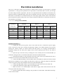
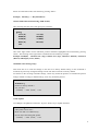
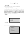
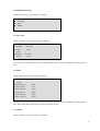
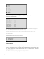
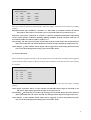
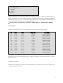
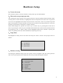
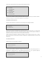
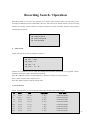
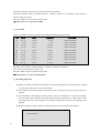
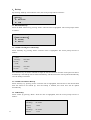
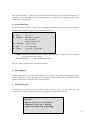
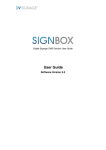
AU-DVRS-04LH
User's Manual
DIGITAL VIDEO RECORDER
Installation and Precaution
1.
Warning
This unit is designed, to be used in indoor condition, to reduce fire and shock hazard, do not expose
the unit to rain or moisture.
Prevent any foreign object or liquid to enter the unit. In case, there is any foreign object or liquid go
inside the unit, cut off the power immediately, and call for a qualified service person to inspect and
test the unit, before putting the unit back to operation.
Do not touch any part of the unit with wet hands.
Do not block any part of ventilation grill / holes of this unit. Do not place other equipment on the
top of this unit.
Place the unit away from direct sunlight, hot source, and radiator.
Install the unit horizontally, and in well ventilation place, to prevent the unit to become overheated.
Do not operate the unit under power supply other than nominal voltage.
2.
Precaution
No user serviceable components inside this unit. Refer servicing to qualified service personnel.
In case of malfunction, contact our local agent or regional representative for repairing.
This unit is delivered without the hard disk by default. Please contact our local agent or
regional representative, so they can install hard disk to suit for your storage and video image
retention requirement.
This unit supports all commercially available IDE hard disk.
In order to ensure stable operation of this unit, IDE hard disk from reputable factory should be
used.
This unit operates under 100-240 VAC, do not operate this unit outside this voltage range.
Once after the unit is connected to power supply source, some part of this unit is already
carrying high voltage, even without turning on the unit by pressing the “Power” button on
remote control and front panel. It is strongly recommended to completely unplug the unit from
power supply source, before opening up the unit for any kind of servicing.
1
Delivery Packing Checklist
This unit is packed with the following accessories, please kindly check immediately after unpacking the
box :
1、 1 no. of power supply cord
2、 1 no. of operating manual
3、 1 no. of Infra-red remote controller
4、 1 set of installation accessories
2
Index
FRONT PANEL………………………………………………...6
REAR PANNEL……………………………………………….. 8
HARD DISK INSTALLATION.................................................. 9
VOLTAGE OUTPUT & SENSOR INPUT AND ALARM
OUTPUT CONNECTION……………………………………..10
POWER ON AND OFF………………………………………...11
1.POWER ON……………………………………………………………………………. .11
2.POWER OFF…………………………………………………………………………… .11
SYSTEM SETUP………………………………………………12
1、TO ENTER MENU .......................................................................................................... 12
2、 MENU AND SCREEN PROMPT OPERATION ................................................................... 12
3、 SETUP MENU ............................................................................................................... 12
ENTER SYSTEM PASSWORD ................................................ 12
1、System Setting....................................................... 13
1.1System Password Setting .............................................. 13
1.2Language Setting ..................................................... 14
1.3Time and Date Setting ................................................ 14
1.4Date Mode ......................................................... 14
1.5Time Indication Position Setting ....................................... 15
1.6Default Value Setting ................................................. 15
1.7SW Update…………………………………………………………………………….15
RECORDING SETTING ............................ 16
1、TO ENTER THE MENU ................................................ 16
2、MENU AND SCREEN PROMPT OPERATION ................................. 16
3、SETUP MENU....................................................... 16
1、Record setting ....................................................... 16
1.1Schedule Recording ................................................. 17
1.1-1One Time ........................................................ 17
1.1-2Daily ........................................................... 17
3
1.1-3Weekly ..........................................................
1.2Event Recording ....................................................
1.2-1Motion Detection ..................................................
1.2-2 Sensor Detection ..................................................
1.3Repeat Recording....................................................
1.4Recording Speed (Frame Rate) ........................................
1.5 Compression Rate (Recording Quality) ..................................
1.6File Deletion .......................................................
1.7File Lock / Unlock ...................................................
17
18
18
19
20
20
20
21
21
HARDWARE SETTING ............................ 23
1.TO ENTER THE MENU ................................................... 23
2.MENU AND SCREEN PROMPT OPERATION .................................... 23
3.SETUP MENU ......................................................... 23
1、Hardware Setting .................................................. 23
1.1PTZ Camera Setting .................................................
1.2PTZ Camera ID .....................................................
1.3Sensor / Alarm Setting ................................................
1.3-1Sensor Type ......................................................
1.3-2Alarm Management Setting ...........................................
1.3-3Alarm output Setting ................................................
1.3-4Alarm out Period ...................................................
1.3-5Manual de-activation of alarm output(Alarm Manual off)....................
1.4Network Setting......................................................
1.4-1Static internet protocol ...............................................
1.4-2Dynamic internet protocol ...........................................
1.4-3Network Password ..................................................
1.5Storage Setting.......................................................
24
24
24
25
25
25
26
26
26
26
27
27
28
RECORDING SEARCH / OPERATION ............... 29
1.Time Search ......................................................
2.Event Search .......................................................
3.List Search ........................................................
4.Recording Operation.................................................
5.Playback operation ..................................................
29
29
30
30
31
OTHER OPERATION .............................. 32
1.Pan Tilt Control..................................................... 32
2.Zoom / Focus Control ................................................ 32
3.Audio Item ........................................................ 33
4.Backup ........................................................... 34
4-1、IEEE 1394 Backup ..................................................................................... 34
4
4-2、USB Backup.............................................................................................. 34
5.Status Indication .................................................... 35
6.SPOT Display ...................................................... 35
7.Hard disk format .................................................... 35
NETWORK SOFTWARE OPERATION ................ 37
1、GRAPHIC USER INTERFACE INTRODUCTION ................................. 37
2、CONNECT AND DISCONNECT............................................. 37
2-1、Signing On ................................................................................................... 37
2-2、Disconnect.................................................................................................... 38
3、LIVE DISPLAY ........................................................ 38
4、PTZ CAMERA CONTROL ............................................... 38
5、BACKUP FILE ........................................................ 39
6、OPEN FILE .......................................................... 40
7、SCREEN EXPAND ..................................................... 40
8、FRAME RATE SETTING ................................................ 41
Specification ............................................................. 42
5
Front Panel
1.Power Button
Turn the unit on or off.
2.Digits Buttons
Change time, password, and input IP address
3.Menu Button
Go to the top level of the menu tree
4.Setup Button
Other operation Menu
5.Channel Select Button
Select the channel. Toggle the screen between QUAD, 1,2,3 or 4
6.SPOT Button
Put the display mode to Spot Mode. Toggle the screen between Quad, Channel 1.2.3 or 4, under Spot
viewing
7.STATUS Button
System status indication
8.Power LED
Power on/off indication
9.HDD LED
HDD operation indication
10.REC LED
REC operation indication
11.Play LED
playback operation indication
12.REC Button
Toggle of recording on and off
13Rewind Button
Active only under playback operation, Toggle between 2X,4X,8X or 16X reverse Play
14.Playback Button
Active only under playback operation. Return the playback to 1X forward playback.
15.Fast Forward Button
Active only under playback operation. Toggle between 2X,4X,8X or 16X forward play
16.Pause/Frame Advance Button
Active only under playback operation. Pause the screen on playback
17.STOP/EXIT Buttons
Active only under playback operation. Stop playback process/Cancel of data input or leave the current
menu tree
6
18.Enter Button
Confirm of the data input
19.Up Button
Up action for menu tree navigation, pan/tilt etc..
20.Left Button
Left action for menu tree navigation, pan/tilt control etc..
21.Right Button
Right action for menu tree navigation, pan/tilt control etc..
22.Down Button
Down action for menu tree navigation, pan/tilt control etc..
23.Search Button
Go to "Search" item under the menu tree. Let user to search for video clip to playback
7
Rear Panel
1.
2.
3.
4.
5.
6.
7.
8.
9.
10.
11.
12.
13.
14.
15.
8
Power Input
Camera Input 1~4
Loop Out 1~4
Video Output
Audio Output
Audio Input 1
Audio Input 2
Sensor Input 1~4
Alarm Output 1~4
RS232 Port
RS485 Port
S-Video Output
USB Port
LAN Port
IEEE 1394 Port
Hard disk installation
This unit is delivered without the hard disk by default. Please contact our local agent or regional
representative, so they provide qualified service personnel to install hard disk to suit for your storage
and video image retention requirement. The unit is not operational before installation of hard disk. The
maximum number of IDE hard disks, which can be installed in this unit is four. The size and number of
hard disks to be installed is to be determined by the video image quality and the online video retention
period requirement, please kindly refer to the storage calculation table below to determine the total size
of hard disks to be installed.
************Storage Table(720X480)
Frame Rate
(Frame/Sec)
Standard
High 1
High 2
240GB
480GB
240GB
480GB
240GB
480GB
25
220hr
440hr
117.9hr
235.8hr
78.5hr
157hr
12.5
440hr
880hr
235.8hr
471.6hr
157hr
314hr
8.3
660hr
1,320hr
353.7hr
707.4hr
235.5hr
471hr
5
1,100hr
5,500hr
589.5hr
1,179hr
392.5hr
785hr
2.5
2,200hr
6,600hr
1,179hr
2,358hr
785hr
1,570hr
1
5,500hr
11,000hr
2,948hr
5,895hr
1,963hr
3,926hr
Installation Procedure :
1、 Unplug the unit from any power source. Once after the unit is connected to power supply
source, some part of this unit is already carrying high voltage, even without turning on the unit by
pressing the “Power” button on remote control and front panel. It is strongly recommended to
completely unplug the unit from power supply source, before opening up the unit for any kind of
servicing.
2、 Open the top of the unit case by undoing the screws. Identify the two hard disk holder (as
indicated in the figure above). Each hard disk holder can hold two IDE Hard Disks.
3、 Install the hard disk(s) on the hard disk rack, and use the screws (provided with this unit as
installation accessories) to fix the hard disk onto the rack securely.
4、Connect the IDE hard disk(s) onto the ribbon cable. If one IDE bus contain more than one hard
disk, then one should be set up as Master and the other as Slave, by setting the jumper on hard disks
respectively (please refer to the installation instruction of the IDE hard disk).
5、Connect the IDE ribbon cable to one of the IDE slot on the main board on the other end.
6、Connect the internal DC supply cable onto each hard disk.
7、Make sure there is no strained ribbon cable and DC supply cable inside, and then close the
casing top. Fasten the casing screws.。
8、Format the IDE hard disk according to the procedure as stated under “Hard Disk formatting”
section of this manual.
9
Voltage Output & Sensor Input and Alarm
Output Connection
Sensor Input
This unit has 4 numbers of isolated Sensor input to take voltage free relay outputs from peripheral alarm
sensors.
These Sensor inputs are protected from high voltage input from outside, by providing the opt-isolated
design
Sensor Input Setup :
Set the sensor type to “no(normal open)” or “nc(normal close)”.
This unit need to input external power supply to connect each sensor.
Alarm Output
Four alarm outputs are built into the system,
This unit need to input external power supply to connect each alarm.
10
Power ON and OFF
1、Power On
Before the first time of turning on the unit for operation, please make sure all points listed in the
“Installation and Precaution” section has been studied and followed.
Double check all connections to the unit is correct, and power supply connection to the unit is
proper.
Double check that IDE Hard Disk(s) are connected and installed properly (and formatted
according to procedure as listed in this manual)
Double check the video format of the unit matches the video format of CCTV and monitor.
If all the above double-checking is done without problems, then peripheral equipment can be
powered on..
Once the power is connected to the unit, the power operation LED should be lit.
If the powering down of the unit happened during scheduled recording, then on powering on, the
unit will go into recording automatically.
If the unit is with recording schedule, and the powering on time is within the schedule recording
period, then the recording will start automatically with the schedule recording per-configured
properties.
2、Power Off
To power off the unit, operator should stop the recording, exit from configuration menu and any
playback operation first.
Operator should press “■” to stop the recording or playback, before powering off the unit.
It is recommended to turn off the unit, before powering down any of the peripheral equipment.
If the unit will be left powered off and not in operation for a long period of time, it is
recommended to unplug it from power source.
The unit should not be powered off during data backup process, in order to prevent data
loss.
The unit should not be powered off during software upgrade process, in order to prevent
failure to restart operation of the unit. In case software upgrade process is interrupted by
accidentally powering off the unit, assistance should be seek from our local agent or regional
representative to repair the unit.
11
System Setup
The unit should be configured using the menu, to tailor suit the unit for specific site operation, if not, the
unit will operate under ex-factory default settings.
1、To enter SETUP
Press “Setup” button on remote controller or front panel to go into Setup Menu.
2、 Menu and screen prompt operation
After entering the menu, operator can navigate the items by using the up button and down button,
either on front panel or remote controller, to highlight the items on the present level of the menu.
To go down one level to the highlighted item under the present level of the menu, “Enter” key
should be pressed either on front panel or remote controller. To go up one level and exit from the
present item, “Exit” key should be pressed either on front panel or remote controller.
When inside dialogue box, operator can use the “Up” or “Down” key to go through the circular
list of items. On pressing the “Enter” key, the selectable field under the item will be showed, and
the field can be navigated by “Up” or “Down” button, and the highlighted field will be selected
on pressing the “Enter” key. Editing of the item will be abandoned, on pressing “Exit” key.
3、Setup Menu
By highlight the “Setup” item on the main menu and press “Enter”, and the screen prompt will be
as follows :
SYS Setup
REC Setup
H/W Setup
Enter System Password
To enter the system setting menu items, the operator will be prompted to enter the system password on
this point. This password protection is to prevent un-authorized alternation of system settings and
recording settings.
Enter password
: __ __ __ __
12
The unit’s system password is a combination of numeric digital between 0 and 9. Numeric key on
remote controller or front panel can be used to enter the password. On entering of the system password,
for security reasons, the on-screen indication is represented by “*”.
The ex-factory default system password is “0000”. It is strongly recommended to change the system
password before putting this unit into actual operation (please refer to later section of this manual for
procedure of changing the system password).
1、System Setting
After entering of system password, the screen prompt will be changed as follows:
Password
Language
Time set
Date format
OSD format
Default setup
SW Update
1.1System Password
By highlighting the “Password” and pressing “Enter”, operator will be prompted to input the new
password. Use the numeric key on remote controller or front panel, to enter a combination of 4 nos.
digits from 0 to 9.
〔Enter new password〕
: __ __ __ __
The default password is “0000”, Enter the new password again.
〔Re-enter password〕
: __ __ __ __
13
After inputting the new system password, the screen prompt will request to enter the new password
again to reconfirm.
1.2Language Setting
By highlighting “Language” item and press “Enter”, the screen prompt will be changed as follows:
Korean
English
Chinese simplified
Chinese traditional
Spanish
French
Japanese
Operator can highlight the desired language and press “Enter” to confirm the selection.
1.3Time and Date Setting
The unit is a time sensitive devices, and a lot of operation is basing on time and date, so the unit should
be set to match the actual time and date to prevent abnormal operation or mistakes in operation. By
selecting “Time Set”, the screen prompt will be changed as follows:
Year :2004
Month :01
Date :10
Time :10 : 00
Use numeric keys on remote controller to input the actual time and date.
Caution: In case there is recordings on the unit already, when the time and date settings is being
changed, searching for video clips after time and date settings changed will not be possible. It is
necessary to delete all recording on the unit before changing the time and date settings.
It can’t enter this menu to set Time & Date during Recording。
1.4Date Mode(Format)
Under this item the screen prompt is as follows:
dd/mm/yy
yy/mm/dd
mm/dd/yy
14
Select one of the date mode, and confirm by pressing “Enter”.
Example) dd/mm/yy ---- Day/Month/Year
1.5Time Indication Position Setting (OSD format)
After selecting this item, the screen prompt is as follows:
〔OSD〕
TTTT(W)
BBBB(W)
TTBB(W)
BBTT(W)
OFF
TTTT(B)
BBBB(B)
TTBB(B)
BBTT(B)
One of the eight modes of time indication position should be highlighted and confirmed by pressing
“Enter”. The meaning of the eight modes is elaborated in the following example:
Example: TTBB(W) – Channel One (Top), Channel Two (Top), Channel 3 (Bottom), Channel 4
(Bottom) and Display Color (White)
1.6Default Value Setting(setup)
This menu item is to return all settings on this unit to ex-factory default setting. If this command is
executed, all previously configured settings will be lost and reverted to ex-factory default.
To confirm on the reverting to default settings, “Enter” key should be pressed. To maintain the present
settings without reverting to default settings, “Exit” key should be pressed.
WARNING :
Restore to factory default!
!
Are you sure?
〔ENTER〕-> YES〔EXIT〕-> NO
1.7SW Update
Via USB port can update the Firmware. To press “Enter” key to Update firmware.
WARNING :
SW Update will be start!!
Make sure SW is in USB memory
Do not Power Off during SW update
〔ENTER〕-> YES〔EXIT〕-> NO
15
Recording Setup
1、To enter the menu
Press “SETUP” button on remote controller or front panel to go into SETUP Menu.
2、Menu and screen prompt operation
After entering the menu, operator can navigate the items by using the up button and down button, either
on front panel or remote controller, to highlight the items on the present level of the menu. To go down
one level to the highlighted item under the present level of the menu, “Enter” key should be pressed
either on front panel or remote controller. To go up one level and exit from the present item, “Exit” key
should be pressed either on front panel or remote controller.
When inside dialogue box, operator can use the “Up” or “Down” key to go through the circular list of
items. On pressing the “Enter” key, the selectable field under the item will be showed, and the field can
be navigated by “Up” or “Down” button, and the highlighted field will be selected on pressing the
“Enter” key. Editing of the item will be abandoned, on pressing “Exit” key.
3、Setup Menu
By highlight the “Setup” item on the main menu and press “Enter”, and the screen prompt will be as
follows:
SYS Setup
REC Setup
H/W Setup
1、Record setting
On entering this item, the operator will be prompted to enter the system password. The numeric keys on
remote controller or front panel should be used to enter the password. After successful entering the
password, the screen prompt will be changed as follows:
Schedule Record
Event Record
Repeat Record
Frame Rate
Compression Rate
Delete Record
Lock/Unlock Rec
16
1.1Scheduled Recording
Under this item, the screen prompt is as follows:
One Time
Daily
Weekly
1.1-1One Time
Under “One Time”, the screen prompt is as follows:
〔Start〕
mm/dd/yy
hh:mm
〔End〕
mm/dd/yy
hh:mm
01/10/04
10:00
01/10/04
19:55
Use numeric key to enter the start and end time and date for the one-shot scheduled recording period of
time.
1.1-2Daily
Under “Daily”, the screen prompt is as follows:
〔Daily〕
* Start (hh:mm)
* End (hh:mm)
* Start (hh:mm)
* End (hh:mm)
* Start (hh:mm)
* End (hh:mm)
09:00
11:30
13:00
18:00
13:00
18:00
Use numeric key to enter the start and end time and date for the one-time scheduled recording period of
time. Three individual period of time can be inputted for one day.
1.1-3Weekly
Under “Weekly”, the screen prompt is as follows:
17
Sunday
Monday
Tuesday
Wednesday
Thursday
Friday
Saturday
Select one of the day under a week, by highlight a day (e.g. Sunday) and press “Enter”. The screen
prompt will be changed as follows:
〔Sunday〕
* Start (hh:mm)
* End (hh:mm)
* Start (hh:mm)
* End (hh:mm)
* Start (hh:mm)
* End (hh:mm)
09:00
11:30
13:00
18:00
13:00
18:00
Use numeric key to enter the start and end time and date for the one-time scheduled recording period of
time. Three individual period of time can be inputted for one day.
Repeat this step of each day of a week, to input recording period(s) of time for 7 days of a week.
1.2Event Recording
Under “Event Record” the screen prompt is as follows:
Motion Detection
Sensor Detection
1.2-1Motion Detection
The Motion Detection can be used to trigger recording of the camera. When a camera picture has an
increase in average change rate, then a “motion is detected”. Motion detection can be associated with a
zone within a camera picture. “Motion detected” in the zone of an individual camera, will trigger
recording of all cameras.
After selection of this item, the screen prompt will be changed as follows:
18
〔Motion Detection〕
#1
STD
SEN
#2
STD
SEN
#3
STD
SEN
#4
STD
SEN
〔OFF〕
〔OFF〕
〔OFF〕
〔OFF〕
Press Up or down to select the camera number, and left or right to select the motion detection recording
property.
Motion Detection: The “Standard”, “Sensitive” or “Off” fields, is to indicate whether the motion
detection for that camera is activated or not, if activated which level of sensitivity is set.
Sensitivity :Two levels, “Standard” or “Sensitive”. Operator should determined the setting basing
on the camera picture condition, including lighting condition, desired sensitivity and type of
environment under surveillance (indoor, outdoor etc..).
Time Setting: The unit will record video clip starting from 30 seconds before the motion detected,
and to 30 seconds after the motion detected. Pre-alarm period is depend on compression rate.
Alarm Output :Select whether alarm output will be triggered on motion being detected. Please
refer to the alarm management setting section for further detail.
1.2-2 Sensor Detection
Sensor detection triggered recording is the recording mode, under which the recording will be triggered
by one of the four Sensor inputs of the unit being in alarm condition. Under this item, the screen prompt
is as follows:
〔Sensor Detection〕
#1
ON
〔OFF〕
# 2 ON
〔OFF〕
# 3 ON
〔OFF〕
# 4 ON
〔OFF〕
Press Up or down to select the camera number, and left or right to select the alarm input recording
property.
Alarm Input Activation: This is to select whether an individual sensor input is activated or off.
The sensor input will be ignored if the input is selected to be off.
Time Setting: :The unit will record video clip starting from 30 seconds before the sensor detected,
and to 30 seconds after the sensor detected. Pre-alarm period is depend on compression rate.
Alarm Output :Select whether alarm output will be triggered on sensor being detected. Please
refer to the alarm management setting section for further detail.
19
1.3Repeat Recording
Under this “Repeat Record” item, the screen prompt is as follows:
〔Repeat Record〕
ON
OFF
If the “Repeat Record” is activated, then the on-line hard disk space will be acting as an FIFO (First In
First Out) buffer, old images will be erased automatically. No operator intervention will be required on
hard disk being full.
In contrast, if the “repeat Record” is not activated, then operator will be prompted on hard disk being
full, no old image will be erased. If the hard disk is full, and no proper operator action is being taken,
then all types of recording will be stopped until there is hard disk space for new recording.
Operator can highlight the desired option, and press “Enter” to confirm.
☞ Default Setup by factory “ON”
1.4Recording Speed (Frame Rate)
Under this “Frame Rate” item, the screen prompt is as follows:
〔Frame Rate〕
30(25.0) fps
15(12.5) fps
10(8.3) fps
6(5) fps
3(2.5) fps
1(1.0) fps
Operator can select one of the several types of frame rate, and press “Enter” to confirm.
Caution: All alarm triggered recording is at maximum <30(25) fps> frame rate, this manual frame
rate setting is only applicable on scheduled recording.
1.5 Compression Rate (Recording Quality)
Under this “Recording Quality” item, the screen prompt is as follows:
20
〔Compression Rate〕
Standard
High-1
High-2
Operator can select one of the three quality level and press “Enter” to confirm. For determination of
quality of recording to be selected, operator should consider the hard disk space available and desirable
retention period of video clips on local hard disk(s). Please refer to the following benchmarking to
estimate one’s need on retention period and hard disk space.
☞ Storage per hour (each Channel) – Standard is 225MB / High-1 is 450MB /High-2 is 675MB
1.6File Deletion
Under this “Delete Record” item, the screen prompt will look like the following sample:
NO
96
97
98
99
100
101
102
103
104
105
106
107
108
DATE
01/10
01/10
01/10
01/10
01/10
01/10
01/10
01/10
01/10
01/10
01/10
01/10
01/10
TIME
11:30
12:00
12:31
13:05
13:30
15:00
15:31
17:02
17:09
17:50
18:21
18:50
20:00
〈PgUp/Dn〉
30 Min
30 Min
30 Min
5 Min
20 Min
30 Min
30 Min
3 Min
30 Min
30 Min
30 Min
30 Min
30 Min
FILE NAME
S040110110000U
S040110120030U
S040110123100U
E040110130540U
E040110133000L
S040110150032U
S040110153150L
E040110170250U
S040110170920U
S040110175000U
S040110182110U
S0401101850430U
S040110200054U
Operator can delete files from the on-line hard disk(s), by highlighting files within one page using up or
down keys, browse previous and next pages by using left or right keys, and confirm deletion of a file by
pressing “Enter”.
1.7File Lock / Unlock
Under this item, operator can lock or unlock individual files. Under this item, the screen prompt will
look like the following sample:
21
NO
96
97
98
99
100
101
102
103
104
105
106
107
108
DATE
01/10
01/10
01/10
01/10
01/10
01/10
01/10
01/10
01/10
01/10
01/10
01/10
01/10
TIME
11:30
12:00
12:31
13:05
13:30
15:00
15:31
17:02
17:09
17:50
18:21
18:50
20:00
〈PgUp/Dn〉
UNLOCK
UNLOCK
LOCKED
UNLOCK
UNLOCK
LOCKED
UNLOCK
UNLOCK
UNLOCK
UNLOCK
UNLOCK
UNLOCK
UNLOCK
FILE NAME
S040110110000U
S040110120030U
S040110123100U
E040110130540U
E040110133000L
S040110150032U
S040110153150L
E040110170250U
S040110170920U
S040110175000U
S040110182110U
S0401101850430U
S040110200054U
Press up or down key to highlight the files, and press “Enter” to toggle the lock / unlock status of the
individual file.
Once a file is locked, it will not be erased from hard disk even if recurring recording is activated.
22
Hardware Setup
1、To enter the menu
Press “SETUP” button on remote controller or front panel to go into SETUP Menu.
2、Menu and screen prompt operation
After entering the menu, operator can navigate the items by using the up button and down button, either
on front panel or remote controller, to highlight the items on the present level of the menu. To go down
one level to the highlighted item under the present level of the menu, “Enter” key should be pressed
either on front panel or remote controller. To go up one level and exit from the present item, “Exit” key
should be pressed either on front panel or remote controller.
When inside dialogue box, operator can use the “Up” or “Down” key to go through the circular list of
items. On pressing the “Enter” key, the selectable field under the item will be showed, and the field can
be navigated by “Up” or “Down” button, and the highlighted field will be selected on pressing the
“Enter” key. Editing of the item will be abandoned, on pressing “Exit” key.
3、Setup Menu
By highlight the “Setup” item on the main menu and press “Enter”, and the screen prompt will be as
follows:
SYS SETUP
REC SETUP
H/W SETUP
1、Hardware Setting
On entering the hardware settings menu, the operator will be prompted to enter the system password.
After correct system password is entered, then the screen prompt will changed as follows:
PTZ camera model
Camera ID
Sensor/Alarm
Network
Storage
Video Output
23
1.1PTZ Camera Setting
Under this item, the screen prompt is as follows:
〔PTZ camera model〕
CNB-102N
PELCO D protocol
Operator can select the PTZ protocol to be employed by this unit to match with the PTZ camera
connected.
☞ Note: the list of supported PTZ protocol will be expanding, please contact our local agent or
regional representative for details.
1.2PTZ Camera ID
Under this item, the screen prompt is as follows:
〔CAMERA ID 〕
# 1
01
# 2
02
# 3
03
# 4
04
Operator can input the PTZ camera ID to individual cameras under this menu item, using numeric keys
of remote controller or front panel. The PTZ camera ID should be unique among all cameras connected
to the same unit.
1.3Sensor / Alarm Setting
Under this item, the screen prompt is as follows:
Sensor type
Alarm Management
Alarm Output
Alarm Period
Alarm Manual Stop
24
1.3-1Sensor Type
Under this item, the screen prompt is as follows:
〔Sensor type〕
* Sensor 1
* Sensor 2
* Sensor 3
* Sensor 4
NC
NC
NC
NC
〔NO〕
〔NO〕
〔NO〕
〔NO〕
Use up and down keys to highlight individual alarm input, and use left or right keys to select the type of
alarm input. Type of Sensor input, can be NO (normally open) or NC (normally close).
1.3-2Alarm Management Setting
Under this item, the screen prompt is as follows:
〔Alarm Management〕
M1
M2
M3
Alarm1
ㅁ
ㅁ
ㅁ
Alarm2
ㅁ
ㅁ
ㅁ
Alarm3
ㅁ
ㅁ
ㅁ
Alarm4
ㅁ
ㅁ
ㅁ
M4
ㅁ
ㅁ
ㅁ
ㅁ
S1
ㅁ
ㅁ
ㅁ
ㅁ
S2
ㅁ
ㅁ
ㅁ
ㅁ
S3
ㅁ
ㅁ
ㅁ
ㅁ
S4
ㅁ
ㅁ
ㅁ
ㅁ
SET
Motion detection for camera 1, 2, 3 and 4 is M1, M2, M3 and M4 respectively. Sensor input 1, 2, 3 and
4 is S1, S2, S3 and S4 respectively. Highlight individual square to associated various M or S to
individual alarm output, and press “Enter” to confirm.
After selecting the management, final confirm by highlighting the “SET” and press “Enter”.
1.3-3Alarm output Setting
Under this window, the screen prompt is as follows:
〔Alarm Output〕
#1
ON
〔OFF〕
#2
ON
〔OFF〕
#3
ON
〔OFF〕
#4
ON
〔OFF〕
25
Use up and down keys to highlight individual sensor input, and use left or right keys to select the
condition of alarm output. Type of sensor input, can be NO (normally open) or NC (normally close).
☞ Default setting by factory “ON”
1.3-4Alarm Out Period
Under this item, the screen prompt is as follows:
〔Alarm Period〕
30 sec
01 min
03 min
10 min
Manual off
This alarm time item, is to configure the alarm output activation duration on associated alarm being
triggered. If “continuous” is selected, then the alarm output will be activated forever until manual
de-activation of the alarm output is being conducted.
Operator can highlight the value and press “Enter” to select.
1.3-5Manual de-activation of alarm output(Alarm Manual off)
Under this item, alarm output can be deactivated by pressing “Enter”.
1.4Network
Under this item, the screen prompt is as follows:
IP Setup
Network Password
1.4-1Static internet protocol
After selecting “IP Setup”, the screen prompt will be changed as follows:
Static IP
Dynamic IP
Operator can select the desired IP status, by using up or down key, followed by “Enter”.
26
If static IP is selected, then the screen prompt will be changed as follows:
IP Address
: 192.168.001.201
GATEWAY
: 192.168.001.001
NETWORK
: 255.255.255.000
Key in the static IP address, Gateway and Sub-Net address using the numeric keys on remote controller.
This network setting is for client software operation over the network.
1.4-2Dynamic internet protocol
If dynamic internet protocol is selected, the screen prompt will be changed as follows:
Static IP
Dynamic IP
Then the unit will obtain an IP address from assigned IP Switch. It will usually take 1 to 2 minutes after
entering this menu item, for the unit to obtain the dynamic IP address. Once the dynamic IP address is
obtained successfully, then this menu item will be quitted automatically.
Caution: During the assignment of Dynamic IP address, lack of response from this unit on “Enter”
button being pressed is normal and do not indicate a malfunction. It might take longer time to boot with
Dynamic IP.
1.4-3Network Password
Under this item, the screen prompt is as follows:
〔Enter new Password〕
:__ __ __ __
Under this item, operator is allowed to change the network password. The network password is a
combination of 4 digits from 0 to 9. The default network password is “1111”. Operator should use
numeric key on front panel or remote controller to input the new password.
〔Re-enter Password〕
:__ __ __ __
27
Operator will be prompted to enter the new password again to re-confirm.
1.5Storage Setting
Under this item, the screen prompt is as follows:
Secondary
Third
Fourth
IEEE 1394
YES
YES
YES
YES
〔NO〕
[NO]
[NO]
〔NO〕
FORMAT
FORMAT
FORMAT
FORMAT
This unit can support 4 numbers of internal hard disk in Maximum. For the first master hard disk, the
formatting and recognizing will be started automatically. For the secondary HDD commands under this
item is required to be used to confirm the existence of hard disk before the hard disks can be used by the
unit.
Select “Yes” for secondary hard disk(s) which exists and has been installed inside this unit, and then
press “Enter” to confirm. -> This version just show up to 2 internal HDD.
If IEEE1394 external storage is connected, “Yes” should also be selected, and press “Enter” to confirm.
1.6Video Output Setting
This mode can select video output condition as Composite out or S-Video out.
28
Recording Search / Operation
Recording search is one of the key functions of a digital video recorder. Video clip searching can be
according to different kinds of information, like time, alarm and event. Search function can be accessed
directly by pressing “Search” button on either front panel or remote controller, then the screen prompt
will changed as follows:
TIME SEARCH
EVENT SEARCH
LIST SEARCH
1.Time Search
Under time search, the screen prompt is as follows:
Year :2004
Month :01
Date :10
Time :10 :46
Numeric key should be used to input the desired time and date information to be targeted. “Enter”
should be pressed to confirm and start the searching.
Press the “CH SEL” button to expand channel 1, channel 2, channel 3 or then channel 4.
Press 5 times to return to the 4-split screen.
Press the “EXIT” button to quit the search menu
2.Event Search
Under “Event Search”, the screen prompt will be like the following sample display
y:NO
DATE
TIME
〈PgUp/Dn〉
FILE NAME
96
97
98
99
100
101
102
103
01/10
01/10
01/10
01/10
01/10
01/10
01/10
01/10
11:30
12:00
12:31
13:05
13:30
15:00
15:31
17:02
1
5
30
21
3
2
8
11
Min
Min
Min
Min
Min
Min
Min
Min
E040110110000U
E040110120030U
E040110123100U
E040110130540U
E040110133000L
E040110150032U
E040110153150L
E040110170250U
29
Select file and press “Enter” key to confirm and start the searching.
Press the “CH SEL” button to expand channel 1, channel 2, channel 3 or channel 4. Press 5times to
return to the 4-split screen.
Press the “EXIT” button to quit the search menu
☞ The first letter “E” express Event REC
3.List Search
Under “List Search”, the screen prompt will be like the following sample display:
NO
DATE
TIME
〈PgUp/Dn〉
FILE NAME
96
01/10
11:30
1 Min
E040110110000U
97
01/10
12:00
5 Min
S040110120030U
98
01/10
12:31
30 Min
S040110123100U
99
01/10
13:05
21 Min
S040110130540U
100
01/10
13:30
30 Min
S040110133000L
101
01/10
15:00
2 Min
E040110150032U
102
01/10
15:31
30 Min
S040110153150L
103
01/10
17:02
11 Min
E040110170250U
104
01/10
18:31
30 Min
S040110153150L
105
01/10
19:02
11 Min
S040110170250U
Select file and press “Enter” key to confirm and start the searching.
Press the “Live” button to expand channel 1, channel 2, channel 3 or channel 4.
Press 5 times to return to the 4-split screen.
Press the “EXIT” button to quit the search menu
☞ The first letter “S” express Schedule REC
4.Recording Operation
Before recording, it should be ensured that the connected peripherals are all powered on, and there
is video signal connected to video inputs already.
Note that this unit records basing on segments. Each recording, from start to stop will form one
segment.
If the hard disk is full during recording, and the system is configured as “recurring recording”,
then the oldest (and unlocked) video clips will be erased automatically, to make room for new
recording. If the unit is not configured as recurring recording, then any types of recording will be
stopped.
By pressing “REC” button, operator will be prompted for system password as follows:
Enter Password
: __ __ __ __
30
After correct password is entered by using numeric keys on front panel or remote controllers, then
the recording of the unit is manually started. This can be actively confirmed by observing
the “REC” indication on screen.
LIVE
REC
If the operator need to stop recording, the “REC” button should be pressed again, then the prompt
for system password will appear again as follows:
Enter Password
: __ __ __ __
On entering correct system password, the recording will be stopped which is actively verified by the
disappear of the “REC” indication on screen.
5.Playback operation
Use “Play” button to start playback.
Switch between “single channel playback” and “quad playback” by pressing “CH SEL”
button. Repeatedly pressing the “CH SEL” button will toggle the playback between
individual camera on single channel mode and then quad playback, in circular style.
During playback, if both audio inputs are activated, then “Audio” button can be press to toggle
between the two audio channels.
The playback is in circular style. In other word, on finishing of a file, the next file will be played,
and on finishing of the last file, the first file will be played. The playback will be circular and
continuous until the “Stop” button is pressed.
The buttons “◀◀”.” ▶▶”. II and “■” are only available during playback
Fast Forward key is used to switch between x2, x4, x8 and x16 playback mode.
Reward key is used to switch between x1, x2, x4, x8 and x16 playback mode.
“Pause” key can be used to temporarily stop the playback and freeze the screen on the latest
frame. ”
After “Pause” is pressed, pressing the fast forward key will switch the playback between x1/2, x1/4
and x1/8 slow motion forward playback modes.
31
“After “Pause” is pressed, pressing the rewind key will switch the playback between x1/2, x1/4,
x1/8 slow motion rewind playback mode.
Pressing “stop” button will stop the playback (without freeze the screen on latest frame).
Other Operation
The “Other operation Menu” items is showed below :
PAN/TILT
ZOOM/FOCUS
AUDIO
BACKUP
STATUS
1、Pan Tilt Control
Press “Enter” when the “Pan/Tilt” item is highlighted, then the following screen will appear :
CAM1
PAN/TILT EXIT
4.3.1 云镜参数
In order to control the PTZ motion of camera, the correct PTZ protocol should be selected. At present,
Pelco-D, CNB-102N, PTZ protocols are supported by this unit.
1.1 Pan Tilt
After entering the Pan Tilt item, pressing the up, down, left and right buttons on remote controller or the
front panel, will move the PT camera to the respective direction. By pressing “Exit” key, operator can
return to the other items of menu operation :
32
Key
Function
Up、Down、Right、Left
Pan Tilt Direction
1.2 Camera selection
By pressing “Pan/Tilt” button on the remote controller or the “Enter” Key on the front panel, camera
selection of CAM2,3 or 4 can be done. Once CAM2, 3 or 4 is selected, pan/tilt control can be achieved
as per section 1.1.
2、Zoom / Focus control
By selecting “Zoom/Focus” item under the menu, the screen prompt will be as follows:
CAM1
ZOOM/FOCUS
EXIT
2.1. Zoom / Focus Control
After entering the Zoom / Focus item of the menu, pressing the up, down, right or left keys will allow
operator to control zoom or focus functions respectively, as listed in the following table :
Key
Function
Left, Right button
Focus Control
Up, Down button
Zoom Control
2.2. Camera selection
By pressing “Pan/Tilt” button on the remote controller or the “Enter” Key on the front panel, camera
selection of CAM2,3 or 4 can be done. Once CAM2, 3 or 4 is selected, focus or zoom control can be
achieved as per section 2.1.
3、AUDIO Item
By selecting “Audio” item under the menu, the screen prompt will be as follows:
〔AUDIO MODE〕
MUTE
AUDIO A
AUDIO B
Choose the required audio output channel.
support the audio
Press the “MUTE” button if you would not like to play
33
4.Backup
By selecting “Backup” item under the menu, the screen prompt will be as follows:
〔Backup〕
IEEE 1394
USB
4.1. IEEE1394 Backup
Select the IEEE 1394 item by pressing “Enter” when the item is highlighted. The screen prompt will be
as follows:
〔IEEE 1394 Backup〕
Partially
Entirely
4.1-1. IEEE 1394 Single Period Backup
Select “Partially” by pressing “Enter” when the item is highlighted. The screen prompt will be as
follows:
〔Start〕
mm/dd/yy
hh:mm
〔End〕
mm/dd/yy
hh:mm
01/10/04
10:00
01/10/04
11:55
Press numeric key on remote controller to input the start and end time and date of the period of data to
be backed up. The backup will be started immediately, and this menu item will be quitted automatically
once the backup is finished.
4.1-2. IEEE 1394 All Files Backup
Select “Entirely” by pressing “Enter” when the item is highlighted, then all files on the internal hard
disk will started to be backed up, once the backup is finished, this menu item will be quitted
automatically.
4.2. USB Backup
Select “USB” by pressing “Enter” when the item is highlighted, then the screen prompt will be as
follows:
34
〔Start〕
mm/dd/yy
hh:mm
〔End〕
mm/dd/yy
hh:mm
01/10/04
10:00
01/10/04
11:55
Press the numeric keys to input the start and end time and date of the period of data to be backed up to
USB device. The USB backup will be started immediately, on completion of the backup, this menu item
will be quitted automatically.
5.Status Indication
By pressing “Enter” when the “Status” item is highlighted, the detailed system status will be displayed.
The following is a sample display of the system status of this unit.
TIME
VERSION
: 10 : 30 : 15
: DRIVER = 1.16.0002
OS = (03/12/24)
APP = 4.0.6(03/12/24)
NETWORK : 192.168.1.200
HDD
: 90.15/100 USED
STATUS
: FP=25FPS CR=2MBPS
* HDD: It displays the capacity of the first HDD, and will display the status of the second HDD
after the fist one is full capacity
* FR : FRAME RATE / CR: COMPRESSION RATE
Press the “EXIT” button to return to the previous menu.
6.SPOT Display
By pressing the “Spot” key, high picture quality live loop through video signal will be displayed on the
monitor output. By pressing the “Spot” key repeatedly, the SPOT mode will be switched between
QUAD, Channel one, two, three or four, in circular manner.
7.Hard disk format
All hard disk is required to be format, before it can be used by the unit to store video clips. On
connection and recognize of IDE hard disk(s), the following screen prompt will appear:
WARNING :
HDD does not exist, or, is not initialized !!
If HDD does not exist, press 〈 EXIT〉
If HDD is not initialized, press〈 ENTER〉
35
☞ If there is no hard disk installed yet, press “Exit” button. If there is hard disk installed
already, press “Enter” to start formatting of the hard disk.
WARNING :
HDD does not exist, or, is not initialized !!
If HDD does not exist, press 〈 EXIT〉
If HDD is not initialized, press〈 ENTER〉
FDISK
FORMAT
MADIRS
OK
OK
OK
Initialized completed,
Press 〈 EXIT〉 to power off
☞ Upon formatting finished, “Exit” button should be pressed, such that the unit will be shut
down automatically and restarted again. After restarting, the unit will go into normal operation
Warning: Formatting will erase all data on the hard disk(s). Before conducting the above
procedure, operator should double check that the data on the installed hard disk(s) can be erased.
36
Network Software Operation
Client software is provide with the unit for operator to operate the unit via remote network connection.,
Remote operation via this client software can include remote monitoring, remote playback, remote
control and remote backup etc..
The recommended minimal personal computer configuration is as follows:
O/S : Windows XP or better
CPU:PIII 800M or better is recommended for minimal operation.(PIII 1G or better is recommended for
optimal operation)
RAM:128M or better
Display card:1024 x 768 resolution, 16bit hi-colour. Ati series, Nivida series, TNT series and Geforce
series display is recommended.
1、Graphic user interface introduction
Client software graphic user interface :
2、Connect and Disconnect
2-1、Signing On:
Click on “Connect” on the GUI. The following dialogue box will pop up. Key in the IP Address and the
37
password (Network password as assigned on the DVR end). Click on OK to continue.
Note:
One DVR allow up to five user to log in simulataneously via the internet or LAN same time.
2-2、Disconnect
Click on the disconnect button, the following dialogue box will pop up. Click “OK” to confirm
disconnect.:
3、Live Display
After connecting, the live image will be displayed automatically. In the midst of operation, when the
client software is playing back some recorded image, then on clicking “Live” button, the playback will
be stop is image will be switch to live image from the DVR.
4、PTZ Camera Control
After clicking on the “Camera Control” the following dialogue box will pop up. The system password
should be entered, and then click the “OK” button to confirm.
After entering the correct password, the operator can control the PTZ and focus of DVR camera
remotely.
Operator can click on ①,②,③,④ to select which camera to be controlled. Use “◀”, “▶”, “▼”,
38
“▲” to control the direction, and use ZOOM, FOCUS“+”, “-”key to control the zoom in/out and focus
near/far functions.
Warning: If the camera control function is left idling for more than one minute, then the control
privileges will be expired and handed over to other user.
5、Backup
Press the “BACKUP” button It appears as follows:
Choose the list up with All list or SET Date to find and Enter the correct system password A
list of recorded files appears Choose the required file to back up.
Enter the required date and time to back up.
* The maximum period of time that can be backed-up to 59 minutes.
39
6、 Open File
After clicking the “Open” button, the following dialogue box will pop up:
Select the desired file Click “OK”. Playback will start automatically.
Backed-up files are saved in the “Mpeg Files” folder, Choose the required file and press Open to open
the file.
File notation illustration 0312171530.MPG --- File start time is 15:30 17 December 2003.
Press “Stop” will stop the playback.
Press “Pause” will freeze the playback at the last frame. “Print” can be operated on paused frame,
so the paused frame can be printed out as hard copy.
☞ Note: *.MPEG files are “Windows Media Player” compatible.
However, the Unified Codec Pack should be installed on PC to playback on
“Windows Media player”
7、 Screen Expand
By clicking the “Screen Expand”
button, the screen will be expanded.
By double click each channel, can be expanded each channel.
40
8.
Frame Rate Setting
If the display does not show live picture, or if the playback speed is not in real-time, please choose the
original speed of the display or playback from this function
41
SPECIFICATION
Description
Signal Format
PAL/NTSC
Video input
1.0V p-p/75Ω,BNC,4ch
Video output
1.0V p-p/75Ω,BNC 1ch,S-Video 1ch,Loop_out,BNC 4ch
Audio input
RCA,2ch
Audio output
RCA,1ch
Sensor input
NO/NC sensor,4ch input
Alarm output
4ch
Network interface
Video resolution
Compression method
HDD
Power
Operating
Temperature
Dimension
42
4ch Digital Video Recorder
10/100 Base-T,Ethernet interface
360×288×4(PAL),360×240×4(NTSC)
TV resolution :250~550 lines
MPEG-II
Support 2ea internal HDD,support 2TB(2,000GB)per each HDD
220V±10%,50Hz
Temperature : -10℃~+50℃;Humidity :< 90%
H:80mm W:370mm D:320mm