1
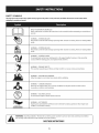
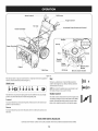
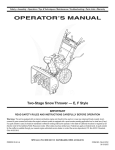
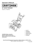
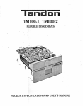
Operator's
Manual
CRRFr MRN
24" SNOW THROWER
Model No. 247.881731
,, SAFETY
o ASSEMBLY
OPERATION
MAINTENANCE
PARTS LIST
o ESPANOL
CAUTION" Before using this
product, read this manual and
follow all safety rules and operating
instructions.
Sears Brands
Management
Corporation,
Visit our website:
Hoffman
www.craftsman.com
Estates,
IL 60179, U.S.A.
FormI/o 769-081740
(June21,2013)
WarrantyStatement
..............................
SafeOperationPractices......................
Assembly
....................................
Operation..................................
Service&Maintenance
......................
Page2 Off-Season
Storage
.............................
Page23
Pages3-6 Troubleshooting
...............................
Page24
Pages
8-11 PartsList...................................
Pages26-43
Pages12-15 RepairProtectionAgreement
...................
Page46
Pages16-22 Espa_ol
.........................................
Page47
CRAFTSMAN
TWOYEARFULLWARRANTY
FORTWOYEARS
fromthedateof purchase,
this productiswarrantedagainstanydefectsin materialor workmanship.
Defectiveproductwill receivefree
repairorfreereplacement
if repairisunavailable.
ADDITIONALLIFETIME
LIMITEDWARRANTY
on UPPERand LOWERCHUTE
FORASLONG
ASITISUSED
bytheoriginalownerafterthesecondyearfromthedateofpurchase,the
upperandlowerchuteofthissnowthrowerare
warrantedagainstanydefectsin materialor workmanship
asverifiedbya Sears
authorizedserviceprovider.With proofofpurchase,
youwill receivea new
chutefreeofcharge.Youareresponsible
for thelaborcostofinstallationandanycostincurredto verifythedefect.
Forwarrantycoverage
detailsto obtainrepairor replacement,
visitthewebsite:www.craftsman.com
ThiswarrantycoversONLY
defectsin materialandworkmanship.
Warrantycoverage
doesNOTinclude:
•
Expendable
itemsthatcanwearoutfrom normalusewithin thewarrantyperiod,includingbutnotlimitedto augers,augerpaddles,drift cutters,skid
shoes,shaveplate,shearpins,sparkplug,air cleaner,belts,andoilfilter.
•
Standard
maintenance
servicing,oil changes,
ortune-ups.
•
Tirereplacement
orrepaircausedbypunctures
from outsideobjects,suchasnails,thorns,stumps,orglass.
•
Tireor wheelreplacement
or repairresultingfrom normalwear,accident,or improperoperationormaintenance.
•
Repairsnecessary
becauseofoperatorabuse,includingbutnot limitedto damagecausedbyover-speeding
theengine,orfrom impactingobjectsthat
bendtheframe,augershaft,etc.
•
Repairsnecessary
becauseofoperatornegligence,
includingbutnot limitedto, electricalandmechanical
damagecausedbyimproperstorage,failureto
usethepropergradeandamountofengineoil,orfailureto maintaintheequipmentaccording
to theinstructions
containedinthe operator's
manual.
•
Engine(fuelsystem)cleaningorrepairscausedbyfueldeterminedto be contaminated
or oxidized(stale).Ingeneral,fuelshouldbe usedwithin 30days
ofitspurchasedate.
•
Normaldeteriorationandwearoftheexteriorfinishes,or productlabelreplacement.
Thiswarrantyisvoidif thisproductiseverusedwhileprovidingcommercial
services
or if rentedto anotherperson.
Thiswarrantygivesyouspecificlegalrights,andyoumayalsohaveotherrightswhichvaryfrom stateto state.
SearsBrandsManagement
Corporation,
NoffmanEstates,
IL60179
Engine Oil:
5W-30
Model Number
Fuel:
Unleaded Gasoline
Serial Number
Engine:
MTD
Date of Purchase
Record the model number, serial number,
and date of purchase above.
© Sears Brands, LLC
2
Thissymbolpointsout importantsafety instructionswhich, if not
followed, couldendangerthe personalsafetyand/or property of
yourself and others.Readandfollow all instructions in this manual
beforeattempting to operatethis machine.Failureto complywith these
instructions
may resultin personalinjury.Whenyou seethis symbol, HEED
ITSWARNING!
CALIFORNIA
PROPOSITION
65
EngineExhaust,someof its constituents,and certain vehiclecomponents
containor emit chemicalsknownto Stateof Californiato causecancerand
Thismachinewasbuilt to beoperatedaccordingto the safeoperation
practicesin this manual.Aswith anytype of powerequipment,
carelessnessor error on the part of the operatorcanresultin seriousinjury.
Thismachineiscapableof amputating fingers, hands,toesandfeet and
throwingdebris. Failureto observethefollowing safety instructions
could
resultin seriousinjuryor death.
Your Responsibility--Restrict the useof this powermachineto
personswho read,understandandfollow the warningsand instructionsin
this manualandon the machine.
SAVETHESEINSTRUCTIONS!
birth defectsor other reproductiveharm.
TRAINING
Disengage
all controlleversbeforestartingtheengine.
Read,understand,andfollowall instructionsonthe machineandinthe
manual(s)beforeattemptingto assembleandoperate.Failureto dosocan
resultinseriousinjury tothe operatorand/orbystanders.Keepthis manual
inasafeplaceforfutureandregularreferenceandfororderingreplacement
Adjustcollectorhousingheightto cleargravelor crushedrocksurfaces.
parts.
Letengineandmachineadjustto outdoortemperaturebeforestartingto
clearsnow.
Befamiliarwith all controlsandtheir properoperation.Knowhowto stop
the machineanddisengagethemquickly.
Neverallowchildrenunder14yearsof ageto operatethis machine.Children
14andovershouldreadandunderstandthe instructionsandsafeoperation
practicesinthis manualandonthe machineandbetrainedandsupervised
byanadult.
Neverallowadultsto operatethismachinewithout properinstruction.
Thrownobjectscancauseseriouspersonalinjury.Planyoursnow-throwing
patternto avoiddischargeof materialtowardroads,bystandersandthe like.
Keepbystanders,
petsandchildrenat least75feetfrom the machinewhileit
isin operation.Stopmachineif anyoneentersthe area.
Exercise
cautionto avoidslippingor falling, especiallywhenoperatingin
reverse.
PREPARATION
Thoroughlyinspect
the areawherethe equipmentisto beused.Removeall
doormats,newspapers,
sleds,boards,wiresandotherforeignobjects,which
couldbetrippedoveror thrownbythe auger/impeller.
Alwayswearsafetyglasses
or eyeshieldsduringoperationandwhile
performinganadjustmentor repairto protectyoureyes.Thrownobjects
whichricochetcancauseseriousinjuryto the eyes.
Donot operatewithout wearingadequatewinteroutergarments.Donot
wearjewelry,longscarvesorotherlooseclothing,whichcouldbecome
entangledin movingparts.Wearfootwearwhichwill improve
footing on
slipperysurfaces.
Usea groundedthree-wireextensioncordandreceptacleforall machines
with electricstartengines.
Neverattemptto makeanyadjustmentswhileengineisrunning,except
wherespecificallyrecommended
inthe operator'smanual.
Safe Handling
of Gasoline:
Toavoid personalinjuryor property damageuseextreme carein handling
gasoline.Gasolineisextremely flammable andthe vaporsareexplosive.
Seriouspersonalinjurycan occurwhengasolineis spilledon yourselfor your
clotheswhichcanignite. Washyour skinandchangeclothesimmediately.
Useonlyanapprovedgasolinecontainer.
Neverfill containersinsidea vehicleor ona truckor trailerbedwitha plastic
liner.Alwaysplacecontainersonthe groundawayfrom yourvehiclebefore
filling.
Whenpractical,removegas-poweredequipmentfrom the truckor
trailer andrefuelit onthe ground.Ifthisis not possible,thenrefuelsuch
equipmenton atrailerwith aportablecontainer,ratherthanfrom agasoline
dispensernozzle.
Keepthe nozzleincontactwith the rim ofthe fuel tankor containeropening
at all timesuntil fuelingiscomplete.Donot usea nozzlelock-opendevice.
Extinguishall cigarettes,cigars,pipesandothersourcesof ignition.
Neverfuel machineindoors.
Neverremovegascapor addfuel whilethe engineishot or running.Allow
engineto coolat leasttwo minutesbeforerefueling.
Neveroverfill fueltank.Filltankto nomorethan1/2inchbelowbottomof
filler neckto allowspacefor fuelexpansion.
Replace
gasolinecapandtightensecurely.
Ifgasolineisspilled,wipeit offthe engineandequipment.Moveunitto
anotherarea.Wait.5minutesbeforestartingtheengine.
To
reduce
firehazards,
keep
machine
free
ofgrass,
leaves,
orother
debris
build-up.
Clean
upoilorfuelspillage
and
remove
any
fuelsoaked
debris.
Never
store
themachine
orfuelcontainer
inside
where
there
isanopen
flame,
spark
orpilot
light
asonawater
heater,
space
heater,
furnace,
clothes
dryer
orother
gas
appliances.
OPERATION
Useonlyattachmentsandaccessories
approvedbythe manufacturer(e.g.
wheelweights,tire chains,cabsetc.).
Whenstartingengine,pull cordslowlyuntil resistanceisfelt, thenpull
rapidly.Rapidretractionofstartercord(kickback)will pullhandandarm
towardenginefasterthanyoucanletgo. Brokenbones,fractures,bruisesor
sprainscouldresult.
Ifsituationsoccurwhicharenot coveredinthismanual,usecareandgood
judgment.
Donot put handsor feetnearrotatingparts,inthe auger/impellerhousing
or chuteassembly.
Contactwith the rotatingpartscanamputatehandsand
feet.
CLEARING
Theauger/impellercontrolleverisasafetydevice.Neverbypassits
operation.Doingsomakesthe machineunsafeandmaycausepersonal
injury.
Handcontactwith the rotatingimpellerinsidethedischargechuteisthe most
commoncauseof injuryassociated
with snowthrowers.Neveruseyourhandto
cleanout the dischargechute.
Thecontrolleversmustoperateeasilyin bothdirectionsandautomatically
returnto the disengagedpositionwhenreleased.
Toclearthe chute:
A CLOGGED
DISCHARGE
CHUTE
a.
SHUTTHE
ENGINE
OFF!
Neveroperatewith amissingor damagedchuteassembly.Keepall safety
devicesin placeandworking.
b.
Wait 10secondsto besurethe impellerbladeshavestopped
rotating.
Neverrunanengineindoors
or inapoorlyventilatedarea.Engineexhaust
containscarbonmonoxide,anodorlessanddeadlygas.
c.
Alwaysuseaclean-outtool, not yourhands.
MAINTENANCE
& STORAGE
Donot operatemachinewhileunderthe influence
of alcoholor drugs.
Nevertamperwith safetydevices.Checktheirproperoperationregularly.
Referto the maintenanceandadjustmentsectionsof thismanual.
Mufflerandenginebecomehot andcancauseaburn.Donot touch.Keep
childrenaway.
Beforecleaning,repairing,or inspecting
machinedisengageall control
leversandstopthe engine.Waituntil the auger/impellercometo acomplete
stop.Disconnect
thesparkplugwire andgroundagainstthe engineto
preventunintendedstarting.
Exercise
extremecautionwhenoperatingonor crossinggravelsurfaces.Stay
alertforhiddenhazardsor traffic.
Exercise
cautionwhenchangingdirectionandwhileoperatingonslopes.Do
not operateon steepslopes.
Checkboltsandscrewsforpropertightnessat frequentintervals
to keepthe
machineinsafeworkingcondition.Also,visuallyinspect
machineforany
damage.
Planyoursnow-throwingpatternto avoiddischargetowardswindows,
walls,carsetc.Thus,avoidingpossiblepropertydamageor personalinjury
causedbyaricochet.
Donot changethe enginegovernorsettingor over-speed
the engine.The
governorcontrolsthe maximumsafeoperatingspeedof the engine.
Neverdirectdischargeat children,bystanders
andpetsor allowanyonein
front of the machine.
Snowthrowershaveplatesandskidshoesaresubjectto wearanddamage.
Foryoursafetyprotection,frequentlycheckall componentsandreplace
with originalequipmentmanufacturer's
(OEM)partsonlyaslistedinthe
Partspagesofthisoperator'smanual.Useof partswhichdonot meetthe
originalequipmentspecifications
mayleadto improper
performanceand
compromisesafety!
Donot overloadmachinecapacitybyattemptingto clearsnowat too fastof
arate.
Neveroperatethismachinewithoutgoodvisibilityor light. Alwaysbesureof
yourfootingandkeepafirm holdon the handles.Walk,neverrun.
Disengage
powerto the auger/impellerwhen transportingor not in use.
Checkcontrolleversperiodicallyto verifytheyengageanddisengage
properlyandadjust,if necessary.
Referto the adjustmentsectioninthis
operator'smanualfor instructions.
Neveroperatemachineat hightransportspeedsonslipperysurfaces.Look
downandbehindandusecarewhenbackingup.
If the machineshouldstartto vibrateabnormally,stopthe engine,
disconnectthe sparkplugwire andgroundit againstthe engine.Inspect
thoroughlyfordamage.Repairanydamagebeforestartingandoperating.
Maintainor replacesafetyandinstruction
labels,asnecessary.
Observe
properdisposallawsandregulationsforgas,oil,etc.to protectthe
environment.
Disengage
all controlleversandstopenginebeforeyouleavethe operating
position(behindthe handles).Waituntil the auger/impellercomesto
acompletestopbeforeuncloggingthe chuteassembly,
makingany
adjustments,or inspections.
Priorto storing,runmachineafewminutesto clearsnowfrom machineand
preventfreezeupof auger/impeller.
Neverstorethe machineor fuelcontainerinsidewherethereisanopen
flame,sparkor pilot light suchasa waterheater,furnace,clothesdryeretc.
Neverput yourhandin the dischargeor collectoropenings.Donot unclog
chuteassemblywhileengineis running.Shutoff engineandremainbehind
handlesuntil all movingpartshavestoppedbeforeunclogging.
Alwaysreferto the operator'smanualforproperinstructionsonoff-season
storage.
4
Checkfuelline,tank,cap,andfittings frequentlyfor cracksor leaks.Replace
if necessary.
Donot crankenginewith sparkplug removed.
Accordingto the ConsumerProductsSafetyCommission
(CPSC)
andthe
U.S.Environmental
ProtectionAgency(EPA),
thisproducthasan Average
Useful Life of seven(7)years,or 60 hoursofoperation.Atthe endof
the Average Useful Life havethe machineinspectedannuallybyan
authorizedservicedealerto ensurethat all mechanical
andsafetysystems
areworkingproperlyandnotwornexcessively.
Failureto dosocanresultin
accidents,
injuriesor death.
DO NOT MODIFY
ENGINE
Toavoidseriousinjuryor death,do notmodifyenginein anyway. Tampering
with the governorsetting canlead to arunawayengineandcauseit to
operateat unsafespeeds.Nevertamper with factory setting of engine
governor.
NOTICE
REGARDING
EMiSSiONS
Engineswhich are certifiedto complywith Californiaandfederal EPA
emissionregulations for SORE
(SmallOff RoadEquipment)arecertified
to operate on regularunleadedgasoline,and mayincludethe following
emissioncontrol systems:EngineModification (EM),OxidizingCatalyst(0C),
SecondaryAir injection(SAI)andThreeWayCatalyst(TWC)if soequipped.
SPARK ARRESTOR
e
This machineisequippedwith an internalcombustionengine andshould
not be usedon or near any unimprovedforest-covered,brushcoveredor
grass-coveredland unlessthe engine'sexhaust systemis equippedwith a
sparkarrestormeeting applicable localor state laws (if any).
Ira sparkarrestoris used,it shouldbe maintained in effective working order
bythe operator. In the State of Californiathe aboveisrequired bylaw (Section
4442of the CaliforniaPublicResourcesCode).Otherstates mayhavesimilar
laws.Federallaws apply on federal lands.
Asparkarrestorfor the muffler is availablethrough your nearestSearsParts
andRepairServiceCenter.
SAFETY
SYMBOLS
Thispage depicts and describes safety symbols that may appear on this product. Read, understand, and follow all instructions on the machine before
attempting
to assemble and operate.
READ THE OPERATOR'S MANUAL(S)
Read, understand,
and follow
all instructions
in the manual(s) before
attempting
to assemble
and
operate
WARNING--
ROTATING BLADES
Keep hands out of inlet and discharge openings
inside
WARNING--
blades
while
machine is running. There are rotating
blades
ROTATING AUGER
Do not put hands or feet near rotating
Contact with the rotating
WARNING--THROWN
This machine
parts, in the auger/impeller
parts can amputate
can cause serious personal
injury.
IS FLAMMABLE
before refueling.
CARBON MONOXIDE
Never run an engine indoors or in a poorly ventilated
monoxide, an odorless and deadly gas.
area. Engine exhaust contains carbon
ELECTRICAL SHOCK
Do not use the engine's
WARNING--
or chute assembly.
OBJECTS
Allow the engine to cool at least two minutes
WARNING--
housing
hands and feet.
may pick up and throw and objects which
WARNING--GASOLINE
WARNING--
machine is running. There are rotating
ROTATING BLADES
Keep hands out of inlet and discharge openings
inside
WARNING--
while
electric starter in the rain
HOT SURFACE
Engine parts, especially the muffler,
muffler to cool before touching.
WARNING:
Your Responsibility--Restrict
the warnings
and instructions
in this manual
become extremely
the use of this power machine
hot during
to persons
and on the machine.
SAVETHESEiNSTRUCTIONS!
6
operation.
Allow engine and
who read, understand
and follow
This page left intentionally blank.
7
NOTE:References
to rightor left sideofthe snowthroweraredeterminedfrom
behindthe unit in theoperatingposition(standingdirectlybehindthe snow
thrower,facingthe handlepanel).
Removing FromCarton
1.
Cutthe cornersof the cartonandlaythe sidesflat on theground.Remove
anddiscardall packinginserts.
2.
Movethe snowthrowerout of the carton.
3.
/
Makecertainthe cartonhasbeencompletelyemptiedbeforediscardingit.
/
/
/
/
/
/
Assembly
1.
Placetheshift leverinthe Forward-6position.
2.
Observe
the lowerrearareaof the snowthrowerto besurebothcablesare
alignedwith rollerguidesbeforepivotingthe handleupward.SeeFigure1.
NOTE:Makecertainthe upperendsof eachcableareseatedproperlyin its
bracket.
3.
4.
Securethe handlebytighteningthe plasticwingknoblocatedonboththe
left andrightsidesof the handle.SeeFigure2. Removeanddiscardany
rubberbands,if present.Theyarefor packagingpurposesonly.
k,.
Figure2
Removewing nut andhexscrewfrom chutecontrolheadandclevispin and
cotterpinfrom chutesupportbracket.Positionchute(forward-facing)over
chutebase.SeeFigure3.
f
ChuteControlHead ................
/
ChuteSupport
Bracket
j
Figure3
J
Figure 1
8
5.
Placechuteontochutebaseandsecurechutecontrolheadto chutesupport
bracketwith clevispinandcotter pinremovedearlier.SeeFigure4.
6.
Finishsecuringchutecontrolheadto chutesupportbracketwith wingnut
andhexscrewremovedearlier.SeeFigure5.
7.
Insertthe chutedirectionalcontrolinto thesupportbracketonthe rearof
the dashpanel.SeeFigure6.
8.
Removethe hairpinclipfrom the rearofthe chutecontrolhead.
9.
Insertchutedirectionalcontrolinto rearofthe chutecontrolhead.Secure
the chutedirectionalcontrolto the chutecontrolheadwith the hairpinclip
removedearlier.SeeFigure7.
f
Figure 6
f
\
Figure
4
f
Figure7
Figure5
9
Set-Up
f
ChuteClean-OutTool
Achuteclean-outtool isfastenedto the top ofthe augerhousingwith amounting
clip.SeeFigure8.Thetool isdesignedto cleara chuteassemblyof iceandsnow.
Thisitem isfastenedwitha cabletieat the factory.Cutthe cabletie before
operatingthesnowthrower.
ChuteClean-OutTool
Neveruseyour handsto clearaclogged chuteassembly,Shutoff engine
and remainbehind handlesuntil all movingpartshavestoppedbefore
usingthe clean-outtool to clearthe chuteassembly.
TirePressure
Underany circumstancedo not exceedmanufacturer'srecommended
psi.
Equaltire pressureshouldbe maintained at all times. Excessivepressure
when seatingbeadsmaycausetirelrim assemblyto burstwith force
sufficient to causeseriousinjury. Referto sidewall of tire for recommended
/
pressure.
/
ii
Figure8
Thetiresareover-inflatedforshippingpurposes.Checkthe tire pressure
before
operatingthesnowthrower.Refertothe tire sidewall for tire manufacturer's
recommended
psianddeflate(orinflate)the tiresasnecessary.
f
NOTE:Equaltire pressure
isto bemaintainedat all timesforperformancepurposes.
Adjustments
Smooth Surface
Skid Shoes
Thesnowthrowerskidshoes
areadjusted
upward
atthefactoryforshipping
purposes.
Adjustthemdownward,
if desired,
priortooperating
thesnowthrower.
It is notrecommendedthat you operate this snowthrower on gravelas
it caneasilypickup andthrow loose gravel,causingpersonalinjuryor
damageto the snowthrower andsurroundingproperty.
Forclosesnowremovalon asmoothsurface,raiseskidshoeshigheronthe
augerhousing.Referto Figure9.
Useamiddleor lowerpositionwhenthe areato beclearedisuneven,suchas
agraveldriveway.
NOTE:Ifyouchooseto operatethe snowthroweron agravelsurface,keep
the skidshoesinpositionformaximumclearancebetweenthe groundand
the shaveplate.
Figure9
Toadjustthe skidshoes:
1.
Loosenthe four hexnuts (two oneachside)andcarriagebolts.Moveskid
shoesto desiredposition.SeeFigure9.
2.
Makecertainthe entirebottomsurfaceof skidshoeisagainstthe groundto
avoidunevenwearon the skidshoes.
3.
Retightennutsandboltssecurely.
UnevenSurface
10
Thedistance
snowisthrowncanbeadjusted
bychanging
theangleoftheupper
chute.Todoso:
Stopthe enginebyremovingthe ignitionkeyandloosenthe plasticwing
knobfoundonthe left sideofthe chuteassembly.
Pivotthe chuteupwardor downwardbeforeretighteningthe wingknob.
SeeFigure10.
2.
Auger Control
Priorto operatingyoursnowthrower, carefully readand follow all
instructionsbelow. Performall adjustmentsto verifyyoursnowthrower is
operating safelyand properly.
Checkthe adjustmentofthe augercontrolasfollows:
1.
Theaugercontrolislocatedon the left handle.SeeFigure11inset.When
the augercontrolisreleasedandinthe disengaged"up"position,the cable
shouldhaveverylittle slack.ItshouldNOTbetight.
2.
Ina well-ventilatedarea,start the snowthrowerengine.Referto Starting
the Engineinthe Operationsection.
.J
Figure10
3.
Whilestandinginthe operator'sposition(behindthe snowthrower),engage
the auger.
4.
Allowthe augerto remainengagedfor approximatelyten (10)seconds
beforereleasingthe augercontrol.Repeatthisseveraltimes.
f
\\
5.
With theaugercontrolin the disengaged
"up" position,walkto the front of
the machine.
6.
Confirmthat the augerhascompletelystoppedrotatingandshowsNOsigns
of motion.Ifthe augershowsANYsignsof rotating,immediatelyreturnto
the operator'spositionandshut off the engine.WaitforALLmovingpartsto
stopbeforeadjustingthe augercontrol.
7.
Toreadjustthe controlcable,loosenthe upperhexbolt onthe augercable
bracket.SeeFigure11.
8.
Positionthe bracketupwardto providemoreslack(ordownwardto increase
cabletension).
9.
Retightenthe upperhexbolt.
10.
Repeatsteps2-6aboveto verifyproperadjustmenthasbeenachieved.
..........
J
Figure11
11
Shift Lever
Drive Control
J
Auger Control
Gas Cap
\
Chute Directional Control
Chute Assembly
\\\
cI
Recoil Starter
Handle
_ugerHousing_
\\_,
Throttle
,L!,
Control
Choke
Control
:lectric Start
Augers
Button
"Skid Shoe
Oil Drain
Electric Starter Outlet
J
Figure12
Nowthatyouhavesetupyoursnowthrower,it'simportantto becomeacquainted
with itscontrolsandfeatures.Referto Figure12.
Key
Shift Lever
Thekeyisasafetydevice.It mustbefully inserted
in
orderfor the enginetostart. Removethe keywhenthe
snowthrowerisnot in use.
I_
1'_1
'
2345
'
'
'
'
6'
NOTE:Donot turn the ignitionkeyinan attemptto start
the engine.Doingsomaycauseit to break.
ChokeControl
Theshift leveris locatedonthe dashpanel.Placethe shiftleverintoanyofeight
positionsto controlthe directionof travelandgroundspeed.
Thechokecontrolisfoundonthe rearofthe engineandis
activatedbyturningthe rotarychokeknobto the CHOKE
position.Activatingthe chokecontrolclosesthe choke
plateon the carburetorandaidsinstartingthe engine.
Forward
Yoursnowthrowerhassixforward(F)speeds.Positionone(1)isthe slowestand
positionsix(6)isthe fastest.
Reverse
Yoursnowthrowerhastwo
reverse(R)speeds.
One(1)lstheslowerand
two(2)ls
thefaster.
MeetsANSiSafetySta.dards
CraftsmanSnowThrowersconformto thesafetystandardof the AmericanNationalStandardsInstitute(ANSI).
12
|
Throttlecontrol
DriveControl/Auger Control Lock
f
DRIVE
CONTROL
Thethrottlecontrolislocatedonthe rearofthe engine.It regulatesthe speedofthe
engineandwill shutoffthe enginewhen movedinto the STOP
position.
Depressing
the primerforcesfueldirectlyintothe
_e
444
engine'scarburetorto aid incold-weatherstarting.
3X
RecoilStarter Handle
Thishandleisusedto manuallystartthe engine.
Thedrivecontrolislocatedonthe right handle.Squeezethe controlgripagainstthe
handleto engagethe wheeldrive.Release
to stop.
Electric Starter Button
Pressing
the electricstarterbuttonengagesthe engine'selectricstarterwhen
pluggedinto a 120Vpowersource.
Electric Starter Outlet
Requires
the useof athree-prongoutdoorextensioncordanda 120Vpowersource/
wall outlet.
OUFill
Thedrivecontrolalsolocksthe augercontrolsoyoucanoperatethe chute
directionalcontrolwithoutinterruptingthesnowthrowingprocess.Ifthe auger
controlisengagedsimultaneouslywiththe drivecontrol,the operatorcanrelease
the augercontrol(onthe left handle)andthe augerswill remainengaged.Release
bothcontrolsto stopthe augersandwheeldrive.
NOTE:Alwaysreleasethe drivecontrolbeforechangingspeeds.Failureto dosowill
resultinincreasedwearon yourmachine'sdrivesystem.
OverheadChute Directional Control
Engineoil levelcanbecheckedandoil addedthroughtheoil fill.
/CHUTE
GasCap
Unthreadthe gascapto addgasolinetothe fuel tank.
DIRECTIONAL
DISCHARGE
LEFT
CONTROL
ADJUSTABLE
CHUTETILT
Auger
Whenengaged,the augerbladesrotateanddrawsnowintothe augerhousing.
ChuteAssembly
Snowdrawninto the augerhousingisdischarged
out the chuteassembly.
J
AugerControl
f
The overheadchutedirectionalcontrolislocatedin the centerofthe snowthrower
AUGER
CONTROL
betweenthe handlepanelandlowerhandle.Tochangethe directioninwhichsnow
isthrown,rotatethe chutedirectionalcontrol.
SkidShoes
Positionthe skidshoesbasedonsurfaceconditions.Adjustupwardforhard-packed
snow.Adjustdownwardwhenoperatingon gravelorcrushedrocksurfaces.
Theaugercontrolislocatedon the left handle.Squeeze
the controlgripagainstthe
handleto engagethe augerandstartsnowthrowingaction.Release
to stop.
13
Clean-OutTool
Donot overfill the fueltank.Afterrefueling,makesurethe tankcapisclosed
properlyandsecurely.
Becarefulnot to spillfuelwhen refueling.Spilledfuel orfuel vapormay
ignite.If anyfuel isspilled,makesurethe areaisdry beforestartingthe
engine.
Neveruseyour handsto clearacloggedchuteassembly.Shutoff engine
and remainbehindhandlesuntil all movingparts havestoppedbefore
usingthe clean-outtool to clearthe chuteassembly.
Avoidrepeatedor prolongedcontactwith skinor breathingofvapor.
Thechutedean-outtool isconvenientlyfastenedto the rearofthe augerhousing
with amountingclip.Shouldsnowandicebecomelodgedin thechuteassembly
duringoperation,proceedasfollowsto safelycleanthe chuteassemblyandchute
opening:
Useextreme carewhen handling gasoline.Gasolineis extremely
flammable andthe vaporsareexplosive.Neverfuel the machineindoorsor
while the engine ishotor running. Extinguishcigarettes,cigars,pipes and
othersourcesof ignition.
1.
Release
boththe AugerControlandthe DriveControl.
2.
Stopthe enginebyremovingthe ignitionkey.
3.
Removethe clean-outtool from the clipwhichsecures
it to the rearof the
augerhousing.
4.
Usetheshovel-shaped
endof the clean-outtool to dislodgeandscoopany
snowandicewhichhasformedinandnearthe chuteassembly.
5.
Refasten
the clean-outtool to the mountingdip on the rearof the auger
housing,reinsertthe ignitionkeyandstartthe snowthrower'sengine.
6.
Whilestandinginthe operator'sposition(behindthe snowthrower),engage
the augercontrolforafewsecondstoclearanyremainingsnowandicefrom
the chuteassembly.
1.
Cleanaroundfuelfill beforeremovingcapto fuel.
2.
Afuel levelindicatoris locatedinthe fuel tank.SeeFigure12inset.Be
carefulnotto overfill.Filltank until fuel reachesthe fuellevelindicatorto
allowspacefor fuelexpansion.
Starting The Engine
Alwayskeephandsandfeet clearof moving parts. Donot usea pressurized
starting fluid. Vaporsareflammable.
flOTE:Allowthe engineto warmupfor afewminutesafter starting.Theenginewill
not developfull poweruntil it reachesoperatingtemperatures.
BeforeStarting Engine
Read,understand,andfollow all instructionsandwarnings onthe
machineandin this manualbeforeoperating.
1.
Makecertainboththe augercontrolanddrivecontrolarein thedisengaged
(released)
position.
2.
Insertkeyinto slot.Makesureit snapsinto place.Donot attemptto turn the
key.
NOTE:Theenginecannotstartwithoutthe keyfully insertedinto the
ignitionswitch.
Oil
Theunit wasshippedwith oil inthe engine.Checkoil levelbeforeeachoperationto
ensureadequateoil in the engine.
ElectricStarter
flO?E:Besureto checkthe engineonalevelsurfacewith the enginestopped.
1.
Removethe oil filler cap/dipstickandwipethe dipstickclean.
2.
Insertthe cap/dipstickinto the oil filler neck,but do NOTscrewit in.
3.
Removethe oil filler cap/dipstick.Ifthe levelislow,slowlyaddoil (5W-30,
with aminimumclassification
of SF/SG)
until oil levelregistersbetweenhigh
(H)andlow (L).
4.
Theelectric starter isequippedwith a groundedplug, andis designedto
operateon 120volt AChouseholdcurrent. It must beusedwith a properly
groundedthree-prong receptacleat all times to avoidthe possibility
of electricshock.Follow all instructions
carefully prior to operating the
electricstarter. DONOTuseelectricstarter in the rain.
flOTE:Donot overfill.Overfillingwith oil mayresultin enginesmoking,hard
startingor sparkplug fouling.
Determinethatyourhome'swring isathree-wiregroundedsystem.Aska licensed
electricianif youarenot certain.
Replace
andtighten cap/dipstickfirmly beforestartingengine.
Ifyouhavea groundedthree-prongreceptacle,proceedasfollows.If youdonot
havethe properhousewiring, DONOTusethe electricstarterunderanyconditions.
Gasoline
Useautomotivegasoline(unleadedor low leadedto minimizecombustionchamber
deposits)witha minimumof87 octane.Gasoline
with up to 10%ethanolor 15%
MTBE(MethylTertiaryButylEther)canbeused.Neveruseanoil/gasolinemixture
or dirty gasoline.Avoidgetting dirt, dust,or waterinthe fuel tank.DONOTuseE85
gasoline.
1.
Pluganextensioncordinto the outletlocatedon the engine'ssurface.Plug
the otherendofextensioncordintoathree-prong120-volt,grounded,AC
outlet inawell-ventilatedarea.
Theextensioncordcan beany length, but must be ratedfor 15ampsat
125volts,groundedand ratedfor outdoor use.
Refuelin awell-ventilatedareawith the enginestopped.Donot smokeor
allowflamesor sparksin the areawherethe engineisrefueledor where
gasolineisstored.
14
2.
ToEngageDrive
Movethrottle controlto FAST
(rabbit)_Jl__ position.
1.
With the
3 Move
choke
tothe
CHOKE
I,'I pos t on
eng
co,d
nestart),fengine
sthrottlecontrolinthe Fast(rabbit)_ _1
into oneof the sixforward(F)positionsor two reverse(R)positions.Selecta
speedappropriatefor thesnowconditionsanda paceyou'recomfortable
with.
warm,placechokein RUNposition.
4.
5.
Pushprimerthree(3)times,makingsureto covervent holeinprimerbulb
whenpushing.Ifengineiswarm,pushprimeronlyonce.Alwayscovervent
holewhenpushing.Coolweathermayrequireprimingto berepeated.
flOTE:Whenselectinga DriveSpeed,usetheslowerspeedsuntilyouare
comfortableandfamiliarwith theoperationof the snowthrower.
Pushstarterbuttonto startengine.Oncethe enginestarts,immediately
releasestarterbutton.Electricstarterisequippedwith thermaloverload
protection;systemwill temporarilyshut-downto allowstarterto coolif
electricstarterbecomes
overloaded.
2.
Squeezethe drivecontrolagainstthe handleandthe snowthrowerwill
move.Release
it anddrivemotionwill stop.
NOTE:NEVER
repositiontheshift lever(changespeedsor directionof travel)
without first releasingthe drivecontrolandbringingthesnowthrowerto a
completestop.Doingsowill resultin prematurewearto the snowthrower'sdrive
system.
Asthe enginewarms,slowlyrotatethe chokecontrolto RUNposition.Ifthe
enginefalters,restartengineandrunwith chokeat half-chokepositionfor a
shortperiodof time,andthenslowlyrotatethe chokeinto RUNposition.
6.
position,moveshift lever
Afterengineisrunning,disconnectpowercordfrom electricstarter.When
disconnecting,
alwaysunplugthe endat the wall outletbeforeunplugging
the oppositeendfrom the engine.
ToEngageAuger
Toengagetheaugerandstartthrowingsnow,squeezethe augercontrol
againstthe left handle.Release
to stopthe auger.
Recoil Starter
ReplacingShearPins
Eachaugerbladeissecuredto the spiralshaftwith ashearpinandbow-tieclip.If
anaugerbladestrikesa foreignobjector icejam, the pinwill shearoff to prevent
damageto the blade.Ifan augerbladedoesnot turn, checkto seeif its pinhas
shearedoff. SeeFigure13.
Donot pull the starter handlewhilethe engine running.
1.
Movethrottle controlto FAST
(rabbit)_ _j position.
2.
Movechoketo the CHOKE
I,.1position(coldenginestart).If engineis
warm,placechokein RUNposition.
3.
Pushprimerthree(3)times,makingsureto covervent holewhenpushing.
If engineiswarm,pushprimeronlyonce.Alwayscoverventholewhen
pushing.Coolweathermayrequireprimingto be repeated.
4.
Pullgentlyonthe starterhandleuntil it beginsto resist,then pullquickly
andforcefullyto overcome
the compression.
Donot releasethe handleand
allowit to snapback.ReturnropeSLOWLY
to originalposition.If required,
repeatthisstep.
5.
NEVER
replacethe augershear pinswith anything otherthan SearsSKU#
88389/0EMPart No.738-04124Areplacementshearpins.Any damageto
the augergearboxor other componentsasa result of failing to do sowill
NOTbe coveredbyyour snowthrower's warranty.
Alwaysturn off the snowthrower's engine and removethe keypriorto
replacingshearpins.
Asthe enginewarms,slowlyrotatethe chokecontrolto RUNposition.Ifthe
enginefalters,restartengineandrunwith chokeat half-chokepositionfor a
shortperiodof time,andthenslowlyrotatethe chokeinto RUNposition.
E
Toavoid unsupervisedengineoperation, never leavethe machine
unattended with the engine running. Turnthe engine off after useand
removekey.
Stopping TheEngine
Afteryouhavefinishedsnow-throwing,runenginefor afewminutesbefore
stoppingto helpdry offany moistureon the engine.
1.
Movethrottle controlto OFFposition.
2.
Removethe key.Removing
the keywill reducethe possibilityof
unauthorizedstartingof the enginewhileequipmentisnot inuse.Keepthe
keyina safeplace.Theenginecannotstartwithout the key.
3.
Wipeanymoistureawayfrom the controlson the engine.
J
15
Figure13
MAINTENANCE
SCHEDULE
Followthe maintenance
schedulegivenbelow.Thischartdescribes
service
guidelinesonly.Usethe ServiceLogcolumnto keeptrackofcompleted
maintenancetasks.Tolocatethe nearestSearsServiceCenteror to scheduleservice,
Beforeperformingany type of maintenance/service,disengageall controls
andstop the engine.Wait until all moving partshavecometo a complete
stop. Disconnect
sparkplug wire and groundit againstthe engine to
preventunintendedstarting.
simplycontactSearsat 1-800-4-MY-HOME
®.
1.
Engineoil level
1.
Check
2.
Looseor missinghardware
2.
Tightenor replace
3.
Unitandengine.
3.
Clean
Ist 5hours
1.
Englneoil
1.
Change
Annuallyor 25hours
1.
Sparkplug
1.
Check
2.
Controllinkagesandpivots
2.
Lubewith light oil
3.
Wheels
3.
Lubewith multipurposeautogrease
4.
GearshaftandAugershaft
4.
Lubewith light oil
Annuallyor 50hours
1.
Englneoil
1.
Change
Annuallyor 100hours
1.
Sparkplug
1.
Change
BeforeStorage
1.
Fuelsystem
1.
Runengineuntil itstopsfrom lackoffuel
EachUseand every 5 hours
GENERAL
RECOMMENDATIONS
CheckingEngine Oil
Beforelubricating, repairing,or inspecting,
disengageall controlsandstop
engine.Wait until all movingparts havecometo acompletestop.
NOTE:Checkthe oil levelbeforeeachuseto besurecorrectoil levelismaintained.
Whenaddingoil to the engine,referto viscositychartbelow.Engineoil capacity
is600ml(approx.20oz.).Donot over-fill.Usea4-stroke,or anequivalenthigh
detergent,premiumquality motoroil certifiedto meetor exceedU.S.automobile
manufacturer'srequirementsforserviceclassificationSG,SF.Motoroilsclassified
SG,SFwill showthisdesignationon thecontainer.
1.
Removethe oil filler cap/dipstkkandwipethe dipstickclean.
2.
Insertthe cap/dipstickintothe oil filler neck,but do NOTscrewit in.
3.
Removethe oil filler cap/dipstick.Iflevelis low,slowlyaddoil until oil level
registersbetweenhigh(H)andlow (L).SeeFigure14.
4.
Replace
andtighten cap/dipstickfirmly beforestartingengine.
J
Changing EngineOil
Figure14
NO/E:Change
the engineoil after the first 5 hoursof operationandoncea season
or every50 hoursthereafter.
1.
Drainfuel fromtank byrunningengineuntil the fueltank isempty.Besure
fuelfill capissecure.
2.
Placesuitableoil collectioncontainerunderoil drainplug.
3.
Removeoil drainplug.SeeFigure15on next page.
4.
Tipunit to drainoil intothe container.Usedoil mustbedisposedofat a
propercollectioncenter.
Usedoil isa hazardouswaste product. Dispose
of usedoil properly. Donot
discardwith householdwaste. Checkwithyour localauthorities or Sears
ServiceCenterfor safedisposal/recyclingfacilities.
Reinstallthe drainplugandtighten it securely.
16
Refillwith the recommended
oil andcheckthe oil level.SeeRecommended
OilUsagechart.Theengine'soil capacityis20ounces.
(%-40 °-20 o 0o 20o 40o
(oc)
Oil Drain
-30° -20° -10 ° 0°
Plug
\
DONOTuse nondetergentoil or 2-strokeengine oil. it couldshorten the
engine'sservicelife.
7.
Reinstallthe oil filler cap/dipsticksecurely.
Figure15
E
Thoroughlywashyour handswith soapandwater assoonaspossibleafter
handlingusedoil.
SparkPlug
CheckingSparkPlug
DONOTcheckfor sparkwith sparkplug removed.DONOTcrankenginewith
sparkplug removed.
Ifthe engine hasbeenrunning,the muffler will bevery hot. Becarefulnot
to touchthe muffler.
NOTE:Checkthe sparkplugonceaseasonor every25 hoursof operation.Change
the sparkplugonceaseasonor every100hours.Toensureproperengineoperation,
the sparkplug mustbeproperlygappedandfreeof deposits.
1.
Removethe sparkplugbootandusea sparkplugwrenchto removethe
plug.SeeFigure16.
2.
Visuallyinspectthe sparkplug.Discardthe sparkplugif thereisapparent
wear,or if the insulatoriscrackedor chipped.Cleanthe sparkplugwith a
wirebrushif it isto be reused.
3.
Measurethe pluggapwith afeelergauge.Correctasnecessary
bybending
sideelectrode.SeeFigure17.Thegapshouldbesetto .02-.03inches(0.600.80mm).
4.
Checkthatthe sparkplug washerisin goodconditionandthreadthe spark
plug inbyhandto preventcross-threading.
5.
Afterthe sparkplug isseated,tightenwith asparkplugwrenchto compress
the washer.
SparkPlugBoot
Figure16
Electrode
NOTE:Wheninstallinganewsparkplug,tighten 1/2-turnafterthe sparkplug
seatsto compressthe washer.Whenreinstallinga usedsparkplug,tighten 1/8- to
1/4-turnafter the sparkplugseatsto compressthewasher.
Thesparkplug mustbe tightened securely.Aloosesparkplug can become
very hot andcan damagethe engine.
Figure
17
17
Lubrication
"I
GearShaft
Thegear(hex)shaftshouldbelubricatedat leastonceaseasonor after every25
hoursof operation.
I.
Topreventspillage,removeall fuel fromtank byrunningengineuntil it
stops.
2.
Carefullypivotthe snowthrowerupandforwardsothat it restsonthe auger
housing.
3.
Removethe lowerframecoverfrom the undersideof the snowthrowerby
removingthe self-tappingscrewswhichsecureit.
4.
Applya lightcoatingof engineoil (or3-in-1oil) to the hexshaft.SeeFigure
18.
NOTE:
Whenlubricatingthe hexshaft,becarefulnot to get anyoil onthe aluminum
driveplateor rubberfrictionwheel.Doingsowill hinderthe snowthrower'sdrive
system.Wipeoffany excessor spilledoil.
Wheels
J
Figure18
f
Atleastonceaseason,removebothwheels.Cleanandcoattheaxleswitha
multipurposeautomotivegreasebeforereinstallingwheels.
Auger Shaft
Atleastonceaseason,removethe shearpinson augershaft.Spraylubricantinside
shaft,andaroundthe spacers
andflangebearingsfoundat eitherendof the shaft.
SeeFigure19.
f_S
/
ShavePlate and Skid Shoes
Theshaveplateandskidshoeson the bottomofthe snowthroweraresubjectto
wear.Theyshouldbecheckedperiodkallyandreplacedwhennecessary.
flOT£:Theskidshoeson thismachinehavetwo wearedges.Whenonesidewears
out,theycanberotated180°to usethe otheredge.
Toremoveskidshoes:
Remove
thetwocarriage
bolts,washers,
andhexflangenutsthatsecure
eachskidshoetothesnowthrower.
Figure19
2.
Reassemble
newskidshoeswith the fourcarriagebolts(two on eachside),
washers,andhexflangenuts.Referto Figure20.
f
Toremoveshaveplate:
1.
Removethe carriageboltsandhexnutswhichattachit to the snowthrower
housing.
2.
Reassemble
newshaveplate,makingsureheadsof carriageboltsareto the
insideof housing.Tightensecurely.SeeFigure20.
NOTE: Angers not shown for clarity.
Figure20
18
4_
Adjustments
f
Shift Cable
If the full rangeof speeds(forwardandreverse)cannotbeachieved,referto the
figureto the right andadjusttheshift cableasfollows:
I,
Placethe shift leverinthe fastestforwardspeedposition(F6).
2.
Loosenthe hex nut onthe shift cableindexbracket.SeeFigure21.
3.
Pivotthe bracketdownwardtotake upslackinthe cable.
4.
Retightenthe hexnut.
/
Drive Control
Whenthe drivecontrolis releasedandinthe disengaged
"up" position,the cable
shouldhaveverylittle slack.ItshouldNOTbetight. Also,if thereisexcessive
slack
inthe drivecableor if the unit experiences
intermittentdrivewhileusing,the cable
mayneedto beadjusted.Checkthe adjustmentof the drivecontrolasfollows:
1.
With thedrivecontrolreleased,pushthe snowthrowergentlyforward.The
unit shouldroll freely.
Figure21
E
2.
Engagethe drivecontrolandgentlyattemptto pushthe snowthrower
forward.Thewheelsshouldnot turn. Theunit shouldnot roll freely.
3.
With thedrivecontrolreleased,movethe shift leverbackandforth between
the R2positionandthe F6positionseveraltimes.Thereshouldbeno
resistanceinthe shift lever.
4,
If anyof the abovetestsfailed,the drivecableisinneedof adjustment.
Proceedasfollows:
a.
Shutoff the engineasinstructedinthe Operationsection.
b.
Loosenthe lowerhexbolt onthe drivecablebracket.SeeFigure22.
c.
Positionthe bracketupwardto providemoreslack(ordownwardto
increasecabletension).
d.
RetJghten
the lowerhexbolt.
Chute
If the chutefallsto remainstationaryduringoperation,the pre-loadof the chute
canbeadjustedbytighteningthe hexnut foundonthe front ofthe chutecontrol
head.
Figure22
Toincrease
the preload,tighten the hexnut clockwisein lg turnintervals.
SeeFigure23.
2.
If thechutedirectionalcontrolisdifficult to crank,decreasethe preloadby
looseningthe hexnut counterclockwise
in lg turnintervals.
//
J
Figure23
19
f
Auger
Control
Referto theAssemblysectionforinstructionson adjustingtheaugercontrolcable.
Skid Shoes
Referto theAssemblysectionforinstructionson adjustingtheskidshoes.
8eR Replacement
Auger Belt
Toremoveandreplaceyoursnowthrower'saugerbelt, proceedasfollows:
I.
Topreventspillage,removeall fuel fromtank byrunningengineuntil it
stops.
2.
Removethe plasticbelt coveronthe front of the enginebyremovingthetwo
self-tappingscrews.SeeFigure24.
3.
Rollthe augerbeltoffthe enginepulley.SeeFigure25.
4.
Carefullypivotthe snowthrowerupandforwardsothat it restsonthe auger
housing.
5.
Removethe framecoverfrom the undersideof the snowthrowerby
removingfourself-tappingscrewswhichsecureit. SeeFigure26.
J
Figure24
,J
Figure 25
.J
Figure 26
2O
Loosenandremovethe shoulderscrewwhichactsasabelt keeper.Referto
Figure27.
Removethe belt fromaroundthe augerpulley,andslipthe belt betweenthe
supportbracketandtheaugerpulley.SeeFigure28.
NOTE:Engagingthe augercontrolwill easeremovalandreinstallationof the
belt.
8.
Reassemble
augerbeltbyfollowing instructionsinreverseorder.
NOTE:DoNOTforgetto reinstallthe shoulderscrewandreconnectthespring
to the frameafterinstallingareplacement
augerbelt.
Performthe AugerControltestoutlinedinthe Assemblysectionof this
manual.
Drive Belt
NOTE:Severalcomponentsmustberemovedandspecialtoolsarerequiredin order
to replacethe snowthrower'sdrivebelt. Contactthe nearestSearsParts& Repair
Centerto havethe drivebelt replaced.
FrictionWheel Removal
Figure27
If the snowthrowerfailsto drivewith the drivecontrolengaged,andperforming
the drivecontrolcableadjustmentfailsto correctthe problem,the frictionwheel
mayneedto bereplaced.Followthe instructionsbelow.Examinethe frictionwheel
rubberfor signsofwearorcrackingandreplacewheelif necessary.
1.
Topreventspillage,removeall fuel fromtank byrunningengineuntil it
stops.
2.
Placethe shift leverinfirst Forward(F1)position.
3.
Carefullypivotthe snowthrowerupandforwardsothat it restson theauger
housing.
4.
Removethe framecoverfrom the undersideof the snowthrowerby
removingthe self-tappingscrewswhichsecureit.
5.
Removethe right-handwheelbyremovingthe screwandbellwasherwhich
secureitto the axle.SeeFigure29.
F
Figure28
J
Figure29
21
6.
f
Carefullyremovethe hexnut andwasherwhichsecures
the hexshaftto
the snowthrowerframeandtightlytap the shaft'sendto dislodgethe ban
bearingfromthe rightsideofthe frame.SeeFigure30.
NOTE:Becarefulnot to damagethe threadsonthe shaft.
7.
Carefullypositionthe hexshaftdownwardandto the [eft beforecarefuNy
slidingthe frictionwheelassemblyoff the shaft.SeeFigure31.
NOTE:If you'rereplacingthe frictionwheelassemblyasawhole,discardthe
wornpartandslidethe newpartontothe hexshall
8.
FoNow
the stepsabovein reverseorderto reassemble
components.
9.
Performthe test previouslydescribedinthe DriveControlsection.
Ifyou'redisassembling
the frictionwheelandreplacingonlythe rubberring,
proceedasfollows:
NOTE:Notall frictionwheelsareserviceable.
If thisisthe case,simplyreplacethe
frictionwheelassembly.
1.
Removethefour screwswhichsecurethe frictionwheel'ssideplates
together.SeeFigure32.
2.
Removethe rubberringfrom betweenthe plates.
3.
Reassemble
thesideplateswith anewrubberring.
J
Figure30
f
NOTE:Whenreassembling
thefriction wheelassembly,
makesurethat the
rubberringiscenteredandseatedpropertybetweenthe sideplates.Tighten
eachscrewonlyonerotationbeforeturningthe wheelclockwiseand
proceedingwith the nextscrew.Repeatthis process
severaltimesto ensure
the platesaresecuredwith equalforce(between6ft-[bsand9ft-[bs).
4.
Slidethe frictionwheelassemblybackontothe hexshaftandfoNowthe
stepsabovein reverseorderto reassemble
components.
5.
Performthe test previouslydescribedinthe DriveControlsection.
J
Figure31
,J
Figure 32
22
If the snowthrowerwill not beusedfor 30daysor longer,or if it is theendof thesnowseasonwhenthe lastpossibilityof snowisgone,the equipmentneedsto bestored
properly.Followstorageinstructionsbelowto ensuretop performancefrom thesnowthrowerformanymoreyears.
PreparingEngine
PreparingSnowThrower
Enginesstoredover30daysneedto bedrainedof fuel to preventdeteriorationand
gumfromforminginfuel systemor on essentialcarburetorparts.If thegasolinein
yourenginedeterioratesduringstorage,youmayneedto havethe carburetor,and
otherfuel systemcomponents,servicedor replaced.
Whenstoringthe snowthrowerin anunventilatedor metalstorageshed,
careshouldbetakento rustproofthe equipment.Usinga lightoil or silicone,
coatthe equipment,especially
anychains,springs,bearingsandcables.
1.
Removeall fuel fromtank byrunningengineuntil it stops.Donot attemptto
pourfuelfrom the engine.
Followlubricationrecommendations.
2.
Changetheengineoil.
3.
Removesparkplugandpourapproximately1oz.(30ml) ofcleanengineoil
into the cylinder.Pullthe recoilstarterseveraltimesto distributetheoil, and
reinstallthe sparkplug.
4.
Cleandebrisfrom aroundengine,andunder,around,andbehindmuffler.
Applya lightfilm ofoil on anyareasthat aresusceptibleto rust.
Removeall dirt fromexteriorof engineandequipment.
Storeequipmentinaclean,dry area.
Inflatethe tiresto the maximumPSI.Referto tire sidewall.
Storeinaclean,dry andwell ventilatedareaawayfromanyappliancethat
operateswith aflameor pilot light,suchasa furnace,waterheater,or
clothesdryer.Avoidanyareawitha sparkproducingelectricmotor,or where
powertoolsareoperated.
Neverstore snowthrower with fuel in tank indoorsor in poorlyventilated
areas,where fuel fumes may reachan openflame, sparkor pilotlight ason
a furnace,water heater,clothesdryeror gasappliance.
If possible,avoidstorageareaswith high humidity.
Keepthe enginelevelinstorage.Tiltingcancausefuelor oil leakage.
23
Disconnect
the sparkplug wireandgroundit againstthe engine to prevent
unintendedstarting. Beforeperforminganytypeof maintenance/service,
disengageall controls andstop the engine.Wait until aHmovingparts
havecometo a completestop.Alwayswear safetyglassesduringoperation
or while performingany adjustmentsor repairs.
Thissection
addresses
minorservice
issues.
Tolocatethe nearestSearsServiceCenterorto schedule
service,
simplycontactSearsat 1-800-4-MY=HOMP.
Engine fails to start
1. Choke control not in CHOKE position.
1. Move choke control to CHOKE position.
2. Spark plug wire disconnected.
2. Connectwire
3. Faulty spark plug.
3. Clean, adjust gap, or replace.
4. Fuel tank empty or stale fuel.
4. Fill tank with clean, fresh gasoline.
5. Engine not primed.
5. Prime engine as instructed
6. Key not inserted.
6. Insert key fully into the switch.
7. Extension
cord not connected
(when
Engine running
erratically/
RPM (hunting
1. Engine running
on CHOKE.
in the Operation
7. Connect one end of the extension
Section.
cord to the
electric starter outlet and the other end to a threeprong 120-volt, grounded, AC outlet.
using electric start button, on models so
equipped).
inconsistent
to spark plug.
1. Move choke control to RUN position.
2. Stale fuel.
2. Fill tank with clean, fresh gasoline.
3. Water or dirt in fuel system.
3. Drain fuel tank by running
with fresh fuel.
4. Carburetor
4.
or surging)
out of adjustment.
5. Over-governed
engine until it stops. Refill
Contact your Sears Parts & Repair Center.
5. Contact your Sears Parts & Repair Center.
engine.
Excessive vibration
1. Loose parts or damaged
Lossof power
1. Spark plug wire loose.
1.
2. Gas cap vent hole plugged.
2. Remove ice and snow from gas cap. Be certain vent
hole is clear.
1. Drive cable in need of adjustment.
1. Adjust drive control cable. Refer to Service and
Maintenance section.
2. Drive belt loose or damaged.
2. Have drive belt replaced. Contact your Sears Parts &
Repair Center.
3. Worn friction
3. Have friction wheel replaced at a Sears Parts &
Repair Center.
Unit fails to propel itself
1. Stop engine immediately
and disconnect spark
plug wire. Tighten all bolts and nuts. If vibration
continues, have unit serviced by a Sears Parts &
Repair Center.
auger.
wheel.
NEED MORE HELP?
Find this
and a[[ your
Get answers
from
other
our team
product
manuals
of home
experts.
online,
Get a personalized maintenance plan for your home.
Find information and tools to help Mth home projects.
24
Connect and tighten
spark plug wire.
Unit fails to discharge snow
1. Chute assembly
clogged.
2. Foreign object lodged
Chute fails to easily rotate
180 degrees
1. Stop engine immediately and disconnect spark
plug wire. Clean chute assembly and inside of auger
housing with clean-out tool or a stick.
in auger.
2. Stop engine immediately and disconnect spark plug
wire. Remove object from auger with clean-out tool
or a stick.
3. Auger cable in need of adjustment.
3. Adjust auger control cable. Refer to Assembly
section.
4. Auger belt loose or damaged.
4. Replace auger belt. Refer to Service and
Maintenance section.
5. Shearpin(s) sheared.
5. Replace with new shear pin(s).
1. Chute assembled incorrectly.
1. Disassemble
directed
NEED MORE HELP?
YotJU,fir_} the _: swe a_] :m,_"
Yeo_:__._a_,a_emy[f_eo_@_,,,,,,,
fo_' free!
o Find this
and a[[ your
Get answers
from
other
our team
product
manuals
of home
experts,
online.
o Get a personalized maintenance plan for your home_
Find information
and tools to help with home projects.
25
chute control and reassemble
in the Assembly
section.
as
Craftsman
Snow
ThrowerModel 247.881731
18
8
o,/"
/
_\\/
1
15
17
\\\\
514
/
36/
31
21
_"/
29
J
33
31
I
34
i27
26
Craftsman SnowThrowerModel 247.881731
m
M
1.
731-2635
Snow Removal Tool Mount
28.
684-04265-4044
Housing
2.
684-04057A-0637
Impeller
12" Dia.
29.
684-04107-0637
Spiral Assembly,
LH
684-04108-0637
Spiral Assembly,
RH
Assembly,
Assembly,
Auger 24"
3.
710-0347
Hex Screw, 3/8-16, 1.75, Gr5
30.
4.
710-0451
Bolt, Carriage,
31.
731-04870
Spacer, 1.25 OD x .75 ID x 1.00
5.
710-04484
Screw, 5/16-18, 0.750
32.
736-0188
Washer, Flat, .76 x 1.49 x .06
Screw, Carriage,
33.
741-0493A
Bushing, Flange, .80 ID x .91 OD
790-00087A-0637
Housing,
5/16-18, .750 Grl
6.
710-0703
7.
712-04063
Nut, Flange Lock, 5/16-18, Nylon
34.
8.
712-04064
Nut, Flange Lock, 1/4-20, Nylon
35.
790-00120-4044
Shave Plate, 2.25 x 23.66
731-06439
Slide Shoe
1/4-20, .750, Gr5
I" Hex Bearing
9.
712-04065
Nut, Flange Lock, 3/8-16, Nylon
36.
10.
714-04040
Cotter Pin, Bow-tie
37.
918-0123A
Housing,
Auger, RH Reduced
11.
936-0159
Washer, Flat, .349 x .879 x .063
38.
918-0124A
Housing,
Auger, LH Reduced
Nut, Push-on, .25 Dia
39.
921-0338
Seal, Oil, .750 x 1.00 x .125
40.
741-0662
Bearing, Flange, .75 x 1.0 x .59
12.
926-04012
13.
731-07525
Chute, Adapter
14.
732-04460
Spring, Extension,
.38 OD x 4.59
41.
710-0642
Screw, Self-tapping,
15.
736-0174
Washer, Wave, .625 x .885 x .015
42.
711-04285
Axle, Auger, 24"
914-0161
Key, Hi-pro 3/16 x 5/8
5" Dia
I/4-20, 0.750
16.
736-0242
Washer, Bell, .340 x .872 x .060
43.
17.
946-04230A
Clutch
44.
715-04021
Pin, Dowel, .25 OD x 1.2
18.
931-2643
Snow Removal Tool
45.
917-04126
Shaft, Worm .75 OD
917-04861
Gear, Worm 20T
Cable, Auger, 47.23"
19.
738-0143
Screw, Shoulder,
.498 x .34, 3/8-16
46.
20.
938-0281
Screw, Shoulder,
.625 x .17, 3/8-16
47.
718-04071
Collar, Thrust
21.
738-04124A
Shear Pin, .25 x 1.50
48.
721-0325
Plug, I/4 x .437
721-0327
Seal, Oil, .75 x I x .131
22.
941-0245
Bearing, Hex Flange x .75 ID
49.
23.
941-0309
Bearing, Ball, .75 ID x 1.85 OD
50.
936-0351
Washer, Flat, .760 ID x 1.50D
24.
756-04224
Flat Pulley, Idler, 2.75 OD
51.
736-3084
Washer, Flat, .51 x 1.12
Housing,
52.
741-0663
Bearing, Flange, .75 x 1.0 x .925
53.
741-0661 B
Bearing, Flange, .75 x 1.00 x .975
54.
710-0276
Screw, Carriage, 5/16-18 x 1.00
25.
790-00075
26.
790-00080A-0637
Bracket, Auger
27.
918- 04171B
Gearbox
Bearing, 1.85 ID
Idler w/Brake
Assembly,
Auger, 24"
27
CraftsmanSnowThrowerModel 247.881731
A
6
49
I
2
A
16
48
44
/
/
,/
/
24
28
28
Craftsman
Snow
ThrowerModel 247.881731
m
m
m
1.
631 -04133A
Handle Assembly,
Clutch
Lock, LH
30.
790-00341-0637
Bracket, Rod
2.
631-04134B
Handle Assembly,
Clutch
Lock, RH
31.
790-00313-0637
Shift Lever
3.
684- 04111 B
Handle Ass'y, Engage, LH
32.
710-04370
Screw, 1/4-20 x 3.00
4.
684-04112C
Handle Ass'y, Engage, RH
33.
710-0627
Screw, 5/16-24 x .750
5.
731-06440A
Chute, Lower
34.
710-04071
Bolt, Carriage,
5/16-18, 1.0
6.
732-04238
Spring, Torsion, .8156 ID x .3038
35.
710-0451
Bolt, Carriage,
5/16-18, .750
7.
914-0145
Click Pin
36.
731-04426A
Chute, Upper, w/Label
8.
710-04586
Screw, 1/4-20 x 1.625
37.
710-1652
Screw, 1/4-20 x .625
9.
790-00219-4044
Panel, Handle, (no cutout)
38.
941-0475
Bushing,
39.
711-04469A
Pin, Clevis
40.
712-04064
Nut, Flange Lock, 1/4-20
#10-24, 1.375
Plastic, .380
10.
710-1233
Screw, Machine,
11.
731-06471
Handle Panel Cover
12.
712-04063
Nut, Flange Lock, 5/16-18, Nylon
41.
710-0572
Screw, Carriage, 5/16-18, 2.25
710-04484
Screw, 5/16-18, 2.25, Gr5
13.
749-04190A-0637
Handle, Upper, RH
42.
14.
936-0185
Washer, Flat, .375 x .738 x .063
43.
914-0101
Pin, Cotter
15.
720-0274
Grip, 1.0 ID x 5.0
44.
790-00248C-0637
Bracket, Panel
684-04250
Rod, Pivot
16.
720-04039
Knob, Shift, Black
45.
17.
918-04933
Gearbox
46.
710-04326
Screw, #8-16 x .50
18.
926-0100
Cap, Push, 3/8 Rod
47.
710-3069
Screw, 1/4-20 x .50
Assembly
19.
732-0193
Spring, .39 x .60 x .88
48.
712-04081A
Nut, Hex, 1/4-20
20.
920-0284
Knob, 5/16-18, Black
49.
731-04894D
Plate, Lock
21.
720-04102
Crank Knob
50.
731-04896B
Cam, Clutch Lock
22.
749-04138B-0637
Handle, Lower
51.
732-04219C
Spring, Clutch Lock
712-3087
Nut, Wing
23.
935-0199A
Bumper, Rubber, .62 OD x .22
52.
24.
736-0262
Washer, Flat, .385 x .870 x .092
53.
714-04040
Bow-Tie Cotter Pin
25.
738-04118
Bolt, Shoulder,
54.
736-04446
Washer, Flat, .25 x .630 x .0515
55.
738-04367
Scr. Shldr. Fig., .312 x 3.5 x 1/4-20
56.
747-05386-0637
Crank, Chute
753-08018±
Chute Kit (Incl. Ref.# 5 & 36)
Screw, Shoulder,
5/16-18 x 0.905
26.
738-04348
27.
684-04311A-0637
.43 x 1.3, 1/4-20
Bracket, Chute Support
28.
946-04397A
Cable, Speed Selector
29.
749-04191A-0637
Handle, Upper, LH
± Available
for warranty
service provider
29
coverage
for details.
only. Contact
a Sears authorized
CraftsmanSnowThrowerModel247.881731
46
41,
/23
7
34
I
30
10
15
73
38
17
3O
Craftsman SnowThrowerModel 247.881731
m
m
38.
738-04493
Axle, .75 x 22"
5.50D
39.
936-0329
Washer, Lock, 1/4
Wheel
40.
710-0809
Hex Screw, 1/4-20, 1.25, Gr5
41.
710-0191
Hex Screw, 3/8-24, 1.25, Gr8
Screw, 5/16-24, .750, Gr5
42.
710-0672
Hex Screw, 5/16-24, 1.25, Gr5
Screw, 1/4-20, 1.000
43.
710-0654A
Screw, Seres, 3/8-16, 1.00
Screw, 1/4-20 x .625
44.
710-1245B
Hex Screw, 5/16-24, .875, Gr8
712-04065
Nut, Flange Lock, 3/8-16, Nylon
45.
710-04484
Screw, 5/16-18 x .750
712-0417A
Nut, Flange, 5/8-18
46.
926-04012
Nut, Push-on, .25 Dia.
731-05353
Cover, Belt
I.
656-04055
Disc Assembly,
2.
684-04153C
Friction
Wheel Assembly,
3.
684-04154B-0637
Support
Bracket, Friction
4.
684- 04156A
Shift Assembly,
5.
710-05339
6.
710-0788
7.
710-1652
8.
9.
Friction
Wheel
Rod
10.
914-0126
Key, Hi Pro, 3/16 x 3/4 Dia.
47.
11.
916-0104
E-ring, .500 Dia.
48.
732-04308A
Spring, Torsion, .850 ID x .354
12.
716-0136
E-ring, Retaining,
49.
736-3082A
Washer, Flat, .45 x 1.5 x .172
936-0119
Washer, Lock .3125
.875 Dia.
13.
916-0231
E-ring, .750 Dia.
50.
14.
917-04209A
Hex Shaft, .8125, 7-Tooth
51.
736-0505
Washer, Flat, .34 x 1.50 x .150
15.
917-04230
Gear, 80-Tooth
52.
748-04053A
Pulley, Adapter,
748-04112B
Spacer, Shoulder,
.75 Dia.
16.
726-0221
Speed Nut, .500
53.
17.
932-0264
Extension
54.
750-04303
Spacer, .875 ID x 1.185 OD
18.
736-0188
Washer, Flat, .760 x 1.490 x .060
55.
750-04477A
Spacer, .340 x .750 x .360
Spring
.317 x .50 x .102
19.
936-0287
Washer, Flat, .793 x 1.24 x .060
56.
954-04050
Belt, Auger
Drive
20.
736-04161
Washer, Flat, .75 x 1.00 x .060
57.
954-04260
Belt, Wheel
Drive
21.
790-00289A-0637
Plate, Cover
58.
756-04109
Pulley, Auger
22.
738-04439
Shoulder
Screw
59.
756-04113
Pulley, Half, V x 2.600 OD
60.
756-04252
Pulley, Half, 3/8-V x 1.7160 OD
.37 x .105, 1/4-20
Drive, 8.1 x .5
23.
738-04184A
Screw, Shoulder,
24.
738-0924A
Screw, 1/4-28, .375
61.
790-00208D
Idler Bracket, Wheel Drive
25.
941-0245
Bearing, Hex Flange x .75 ID
62.
684-04169
Idler Pulley Assembly
750-04571
Spacer, Shoulder,
26.
941-0563
Bearing, Ball, 17 x 40 x 12
63.
27.
946-05067
Clutch Cable, Wheel, 44.95"
64.
735-04099
Plug, 3/8 ID
28.
935-04054
Rubber, Friction
Wheel, 5.50D
65.
735-04100
Plug, 1/2 ID
712-04064
Nut, Flange Lock, 1/4-20, Nylon
.26 x .79 x .538
29.
748-0190
Spacer, .508 ID x .75 OD x .68
66.
30.
756-0625
Roller, Cable
67.
710-0751
Hex Screw, 1/4-20, .620, Gr5
31.
790-00096A-0637
Front Guide Bracket, Auger Cable
68.
732-04311A
Spring, Torsion, .750 ID x .968
32.
790-00180C-4044
Frame
69.
712-04063
Nut, Flange Lock, 5/16-18, Nylon
33.
790-00206A-0637
Guide Bracket, Auger Cable
70.
936-3015
Wash., Flat, .469 x .875 x .105
34.
790-00207C
Guide Bracket, Drive Cable
71.
790-00217A-0637
Pivot Bracket, Speed Selector
35.
790-00316-4044
Cover, Frame
72.
790-00218A-0637
Shift Bracket, Speed Selector
36.
634-04167A-0911
LH Wheel Assembly
73.
731-08181
Spacer, Axle
634-04168A-0911
RH Wheel Assembly
N/A
731-04873
Spacer, 1.25 x .75 x 3.0
37.
Engine (see breakdown)
MTD Model No. 952Z270-SUA
31
Craftsman
EngineModel270-SUAForSnowModel 247.881731
24
23
23
2
21
D _
19
951-11282
Muffler
Assembly
20
710-05001
Muffler
Stud
20
951-14190
Muffler
Stud Kit
21
951-11289
Muffler
Gasket
22
712-04214
Nut- M8
23
710-04915
Bolt - M6 X 12 Zin
24
951-10642B
Muffler
32
Shroud
o
ii
Craftsman EngineModel270-SUAForSnowModel 247.881731
41
_42
°0
37
35
D _
34
951-10634
Shroud-Engine
35
712-04213
Nut
36
951-11284
Choke Knob
37
951-10757
Throttle
39
951-10637
Switch-Ignition
4O
731-05632
Ignition
41
951-10640
Push Rod-Choke
42
951-10635
Air Filter Heating
43
710-04943
Bolt-M6
33
Knob
Key Switch
1X28M Spec
o
o
Craftsman EngineModel270-SUAForSnowModel 247.881731
131- Gasket
Kit-Complete
132-Gasket
Kit-External
133- CompleteEngine
34
Craftsman EngineModel270-SUAForSnowModel 247.881731
D _
o
0
50
951-12111
Piston Ring Set
51
951-11632
Piston Pin Snap Ring
52
951-12007
Piston
53
951-11633
Piston Pin
54
710-04915
Bolt- M6 X 12 Zin
55
951-11113
Shield - Air
56
951-11573
Connecting
57
951-14053
Governor
58
736-04461
Washer
59
951-11902
Governor
60
714-04078
Cotter Pin
61
951-11575
Camshaft
62
951-11369
Bearing
63
951-10307
Key:Flywheel
64
951-11247A
Crankshaft
65
951-11576
Governor
66
715-04092
Pin-Dowel
67
715-04096
Dowl Pin 9X14
68
951-11371
Crankcase Cover Gasket
69
951-12125
Crankcase Cover
Rod Assembly
Shaft
Seal
Assembly
Kit (Incl. 62,63,64,74,79)
Gear/Shaft
951-11246
Crankcase Cover Kit (Incl. 62,68-74)
70
710-04932
Bolt
71
951-11283
Oil Fill Plug Assembly
73
951-11577
O-Ring 15.8 X2.5
74
951-11368
Oil Seal
75
951-11249
Crankcase Kit (Incl. 59,62,74,75,79)
951-11060B
Shortblock
Assembly
(Incl. 4,21,27-29,44,46,
76
951-11350
Oil Drain Pipe
77
736-04440
Washer
78
710-04906
Bolt- Drain Plug
79
951-11370
Oil Seal
130
951-10641
Oil Drain Assembly
131
951-11059A
Gasket Kit-Complete
47, 50-53,56-79)
(Incl. 4,21,27-29,32,44,58,59,68,74,77,79)
132
951-10661B
Gasket Kit-External
133
952Z270-SUA
Complete
35
Engine
(Incl. 4,21,27 29,32,77)
Craftsman EngineModel270-SUAForSnowModel 247.881731
18
15
44
_p
49
13
_
U"
-"45
129
17
131- GasketKit-Complete
132-GasketKit-External
133- CompleteEngine
36
46 _46
Craftsman EngineModel270-SUAForSnowModel 247.881731
ID -
o
0
1
710-04968
Flange Bolt M6
2
951-11054A
Valve Cover
3a
731-07059
Hose-Breather
3b
726-04101
Clamp-Breather
4
951-11565
Valve Cover Gasket
5
951-12000
Intake Valve Spring
6
951-11892
Rocker Arm Assembly
7
751-11124
Nut - Pivot Lockin
8
751-11123
Nut - Valve Adjust
9
951-11893
Rocker Arm
10
710-04902
Bolt - Pivot
11
951-12002
Exhaust Valve Adjuster
12
951-12003
Exhaust Valve Spring Retainer
13
951-12004
Valve Spring
14
951-11894
Intake Valve Seal
15
710-04933
Bolt - M8 X 55 Zin
16
951-11895
Push Rod Guide
17
951-10722B
Cylinder
18
951-10292
Plug:Spark
44
951-11572
Gasket-Cylinder
45
951-10648
Kit-Push Rod
46
951-11899
Tappet
47
715-04108
Pin-Dow110
48
951-10647A
Valve Kit
49
951-10647A
Valve Kit
129
951-12626
Valve Cover Kit
131
951-11059A
Gasket Kit-Complete
Hose
Retainer
Head Assembly
(Incl. 4-14,16,17,21,27-29, 44,48,49)
Head
X 16
(Incl. 4,21,27-29,32,44,58,59,68,74,77,79)
132
951-10661B
Gasket Kit-External
133
952Z270-SUA
Complete
37
Engine
(Incl. 4,21,27 29,32,77)
Craftsman
EngineModel270-SUAForSnowModel 247.881731
134- CarburetorKit- Deni
135- CarburetorKit- Huayi
27
28
3O
w
31_
38
Craftsman EngineModel270-SUAForSnowModel 247.881731
II _
o
w
25
710-04939
Stud-Carb
26
710-04910
Stud-
27
951-11567
Gasket-Carb
28
951-11896
Carburetor
Insulat
29
951-11569A
Carburetor
Gasket
30
951-10639A
Primer
30
951-11824
Primer Bulb
31
951-14026A
Carburetor
Assembly
- Huayi
31
951-14027A
Carburetor
Assembly
- Deni
32
951-11897
Carburetor
Gasket
33
951-11112
Bracket-
134
951-14154
Carburetor
135
951-12788A
a
n/a
Choke Shaft
b
n/a
Choke Plate
C
n/a
Throttle
Shaft
d
n/a
Throttle
Plate
e
710-05469
Screw M3x5
f
736-04638
LockWasher
g
n/a
Gasket, Throttle
h
n/a
Idle Jet Assembly
I
n/a
Idle Speed Adjusting
J
n/a
Mixture
k
951-11699
Primer Hose
I
951-11906
Hose Clamp
m
n/a
Carburetor
n
n/a
Float Pin
o
n/a
Emulsion
P
951-12875
Float Needle Valve
q
n/a
Main Jet
r
n/a
Needle Valve Spring
s
n/a
Float
t
951-11589
Fuel Bowl Gasket
U
n/a
Fuel Bowl
V
951-11348
Fuel Bowl Gasket
W
710-04945
Fuel Bowl Mounting
X
951-11349
Fuel Drain Plug Gasket
Y
710-04938
Fuel Drain Plug
M6X 105
Insulator
Choke Control
Kit- Deni
(Incl. h,n,o,p,q,r,s,t,u,x)
Carburetor
Kit- Huayi
(Incl. h,n,o,p,q,r,s,t,u,x)
39
Plate
Screw
Screw
Body
Tube
Bolt
Craftsman EngineModel270-SUAForSnowModel 247.881731
82
84
92
85
8O
951-10646
Ignition
81
951-11110
Shield - Air Flow
82
710-04940
Bolt
83
710-04919
Bolt - Flange M6
84
951-12416
Flywheel
85
951-10934
Cooling
86
951-10911
Starter Cup
87
712-04209
Nut- M14
88
710-04915
Bolt- M6X 12 Zin
9O
951-10663A
Fan Cover Complete
91
736-04455
Flat Washer-Recoil
92
710-04974
Flange Bolt M6
93
951-14151
Recoil Start Assembly
4O
Coil
Fan
Craftsman EngineModel270-SUAForSnowModel 247.881731
,114
115
104
94
105
D
_
o
O
D
-
o
107
951-11914
Engine/Dipstick
Bolt-M6 X 12
108
710-04905
Bolt
Shield - Governor
109
710-04915
Bolt-
Governor
110
951-11913
Oil Fill Tube Assembly
111
951-11381
O-Ring
Rod-Governor
112
951-10656
Dipstick
113
951-11904
O-Ring Dipstick
114
951-12482
Dipstick
94
951-10758
Throttle
95
710-05103
96
951-I 1108
97
951-I 1935
98
951-10664
Spring-Throttle
99
951-I0665
Control
Assembly
Spring
Return
Governor
Cover
M6 X 12 Zin
Tube
101
951 -l I 106
Bracket-
102
712-04212
Nut-
103
710-04908
Bolt - M6 X 21 Gov
115
951-12533
Fuel Cap
951-11933
Fuel Level Indicator
951-10653B
Fuel Tank
M6
104
951-I1700
Hose Clamp-Carb
116
105
951-I0650
Kit-Fuel Line
117
106
710-04915
Bolt - M6 X 12 Zin
41
Assy
Craftsman EngineModel270-SUAForSnowModel 247.881731
118
119
120
123
121
121
1_127
124
28
m
D -
o
118
710-04914
Bolt- Flange M6
119
951-11680
Flexible Clamp
120
951-11114
Bracket-
121
712-05015
Nut
122
710-04965
Screw M4 X 55
123
710-04935
Screw - M4 X 60
124
710-05182
Bolt-M6 X 32
125
715-04088
Pin - Dowel
126
951-I0645A
Electric Starter
127
710-04915
Bolt- M6X 12 Zin
128
951-11109
Shield - Blower Housing
42
Switch Housing
e
Mount
Craftsman SnowThrowerModel247.881731
777S32636
100/.I,
777X43688
IIO-NV=IIO
"lVflNVlAIS,EIOIVEI3dO
QV:IEI"g
"S:IOV:IEII1S
"13MEI9NO9NIIVEI3dO
N3HMNOIlflVOVUIX3]Sfl "SU3QN¥1S_8
IV 39UVHO$10
IO]UIOH]A3N'S]IUflFNI $133r80 NMOHHIOlOAV01 "_
"3NIHOV_9NIOIAU3SUO9NIOOO13Nfl
3UO_3BO3ddOIS3MH SIUVd9NIAOW11VlllNfl S]IONVH
ONIH38NIV_3UONV'3NIgN3dOIS'$83A31HOLfllO
39VgN3SIO
"_
"31flHO399VHOSIO901ONflO11001 lflO'NV310 3sn "_
•133:10NVSONVH
31VlfldWVNV3U39flVUOU3113dWI
HIlM
IOVINO3"EI:IOflV
ONVU:rl"lqd_l ONIIVIOEII_OEI-I
IVMV d:l:l)l"L
J
777D18152
777S32236
777D16340
777122363
777D16355
777123031
777123030
777D18044
43
FEDERAL
and/or CALIFORNIA
EMISSIONCONTROL
WARRANTYSTATEMENT
YOURWARRANTYRIGHTSANDOBLIGATIONS
MTD Consumer Group Inc, the United States Environmental
Protection Agency (EPA), and for those products
California, the California Air Resources Board (CARB) are pleased to explain the emission (evaporative and/or
warranty
on your 2013 and later small off-road
spark-ignited
engine and equipment
(outdoor
equipment
engines
must be designed,
built and equipped
to meet the State's stringent
equipment
engines
must be designed,
built, and equipped
to meet the U.S. EPA small off-road
equipment
anti-smog
certified
exhaust)
engine).
standards
engine
diagnosis,
condition
exists, MTD Consumer
Group Inc will repair your outdoor
equipment
new outdoor
regulations).
of time listed below, provided
Your ECS may include parts such as the carburetor, fuel-injection
system, ignition system, catalytic converter,
valves, canisters, filters, vapor hoses, clamps, connectors,
and other associated emission-related
components.
Where a warrantable
In California,
(in other states, outdoor
spark ignition
Consumer Group Inc must warrant the ECSon your outdoor equipment
engine for the period
abuse, neglect, or improper maintenance
of the outdoor equipment
engine.
for sale in the state of
control system (ECS)
MTD
there has been no
fuel tanks, fuel lines, fuel caps,
engine at no cost to you including
parts, and labor.
MANUFACTURER'S
WARRANTYCOVERAGE:
This emission
control system is warranted
for two years. If any emission-related
part on your outdoor
part will be repaired or replaced by MTD Consumer Group Inc. In the event that a component
Manufacturer's
equipment warranty, the longer coverage period will apply.
equipment
is covered
engine
for longer
is defective,
the
than two years by the
/
OWNERSWARRANTY
RESPONSIBILITIES:
As the outdoor equipment
engine
Consumer Group Inc recommends
Group Inc cannot deny warranty
As the outdoor
your outdoor
equipment
equipment
owner, you are responsible
that you retain all receipts
for performance
of the required maintenance
listed in your owner's manual. MTD
covering maintenance
on your outdoor equipment
engine, but MTD Consumer
solely for the lack of receipts.
engine
owner, you should
however
be aware that MTD Consumer
engine or a part has failed due to abuse, neglect,
improper
Group Inc may deny you warranty
maintenance,
or unapproved
coverage
if
modifications.
You are responsible for presenting your outdoor equipment
engine to MTD Consumer Group Inc's distribution
center or service center as soon
as the problem exists. The warranty repairs should be completed
in a reasonable amount of time, not to exceed 30 days. If you have a question
regarding
http://su
your warranty
pport.mtd
coverage,
you should contact
the MTD Consumer
Group Inc Service Department
at 1-800-800-7310
or at
prod ucts.com.
GENERALEMISSIONS
WARRANTYCOVERAGE:
MTD Consumer
designed,
Group Inc warrants
built, and equipped
cause the failure of a warranted
The warranty
period
Subject to certain
1.
to the ultimate
so as to conform
part for a period
Any warranted
and exclusions
regulations;
equipment
Group Inc according
remainder
of the period.
for replacement
to subsection
as required
Any warranted
part that is scheduled
stated above. Any such part repaired
only for regular inspection
or replaced under warranty
3.
Any warranted
for replacement
part that is scheduled
replacement
as required
to an ultimate
maintenance
(4) below. Any such part repaired
2.
of time before the first scheduled
that the outdoor
on emission-related
stated above. If the part fails during the period of warranty
Consumer
period
purchaser
and (2) free from defects
engine is delivered
as stated below, the warranty
part that is not scheduled
period
and each subsequent
equipment
in materials
engine
is: (1)
and workmanship
purchaser
or first placed into service.
parts is as follows:
in the written
coverage,
instructions
supplied
the part will be repaired
or replaced
under warranty
is warranted
or replaced
will be warranted
for the
in the written instructions
supplied is warranted for the warranty
will be warranted for the remaining warranty period.
maintenance
in the written
instructions
supplied
date for that part. If the part fails before the first scheduled
Repair or replacement
to the owner.
5.
Notwithstanding
of any warranted
the provisions
service the subject engines
6.
The outdoor
equipment
emission-related
7.
MTD Consumer
warranty
8.
Throughout
warranted
9.
herein, warranty
part, provided
the off-road
herein must be performed
services or repairs will be provided
for diagnostic
that such diagnostic
Group Inc is liable for damages
parts sufficient
provisions
is warranted
replacement,
at a warranty
at all of our distribution
period
station
for the
the part
under
at no charge
centers that are franchised
or equipment.
engine owner will not be charged
warranted
of any warranted
Any replacement
part under the warranty
for
by MTD
will be repaired or replaced by MTD Consumer Group Inc according to subsection (4) below. Any such part repaired or replaced
warranty will be warranted for the remainder of the period prior to the first scheduled replacement
point for the part.
4.
that
of two years.
begins on the date the outdoor
conditions
the warranty
purchaser
with all applicable
to other engine
labor that is directly
work is performed
or equipment
associated
at a warranty
components
with diagnosis
of a defective,
station.
proximately
caused by a failure under
part.
engine
and equipment
warranty
to meet the expected
demand
part may be used in the performance
the owner. Such use will not reduce the warranty
period
stated above, MTD Consumer
Group Inc will maintain
a supply of
for such parts.
of any warranty
obligations
maintenance
of MTD Consumer
or repairs and must be provided
Group Inc.
without
charge to
to
10. Add-on
ormodified
partsthatarenotexempted
bytheAirResources
Board
maynotbeused.
Theuseofanynon-exempted
add-on
or
modified
partsbytheultimate
purchaser
willbegrounds
fordisallowing
awarranty
claims.
MTDConsumer
Group
Incwillnotbeliable
to
warrant
failures
ofwarranted
partscaused
bytheuseofanon-exempted
add-on
ormodified
part.
WARRANTED
PARTS:
The repair or replacement
of any warra nted part otherwise eligible for warranty coverage may be excluded from such warranty coverage if
MTD Consumer Group Inc demonstrates
that the outdoor equipment
engine has been abused, neglected, or improperly
maintained, and that
such abuse, neglect,
any adjustment
coverage.
Further, the coverage
The following
1.
or improper
of a component
emission
Fuel Metering
warranty
maintenance
was the direct cause of the need for repair or replacement
that has a factory
under this warranty
parts are covered
installed,
extends
and properly
operating,
adjustment
limiting
of the part. That notwithstanding,
device is still eligible
only to parts that were present on the off-road
for warranty
engine and equipment
purchased.
(if applicable):
System
Cold start enrichment
Carburetor
system (soft choke)
and internal
parts (or fuel injection
system)
Fuel pump
Fuel tank
2.
Air Induction
System
Air cleaner
Intake manifold
3.
Ignition
System
Spark plug(s)
Magneto
4.
ignition
system
Exhaust System
Catalytic
converter
SAI (Reed valve)
5.
Miscellaneous
Items Used in Above System
Vacuum, temperature,
Connectors
6.
Evaporative
position,
time sensitive valves and switches
and assemblies
Control
Fuel hose
Fuel hose clamps
Tethered
Carbon
fuel cap
canister
Vapor lines
050790 Rev.A
Congratulations
onmakingasmartpurchase.
YournewCraftsman
®productisdesignedandmanufacturedfor yearsof
dependableoperation.Butlikeall products,it mayrequirerepairfromtime to time.That'swhenhavinga RepairProtection
Agreementcansaveyoumoneyandaggravation.
Here'swhat the Repair ProtectionAgreement_ includes:
[] Expertservice byour 10,000
professional
repairspecialists
[] Unlimitedservice and nocharge for partsandlaboronallcoveredrepairs
[] Productreplacementupto $1500if yourcoveredproductcan'tbefixed
[] Discountof 25%from regularpriceof serviceandrelatedinstalled
partsnot coveredbythe agreement;also,25%off
regularpriceof preventivemaintenance
check
[] Fasthelp by phone- wecallit RapidResolution- phonesupportfromaSearsrepresentative.
Thinkof usasa"talking
owner'smanual."
Onceyoupurchasethe RepairProtectionAgreement,a simplephonecallisallthat it takesfor youto scheduleservice.You
cancallanytimedayor night,or scheduleaserviceappointmentonline.
TheRepairProtectionAgreementisa risk-freepurchase.If youcancelfor anyreasonduringthe productwarrantyperiod,
wewill provideafull refund.Or,a proratedrefundanytimeafterthe productwarrantyperiodexpires.Purchase
yourRepair
ProtectionAgreementtoday!
Somelimitations and exclusionsapply. Forpricesand additional informationin the U.S.A.call 1-800-827-6655.
_Coveragein Canadavarieson someitems. Forfull details call SearsCanadaat 1-800-361-6665.
SearsInstallationService
ForSears
professional
installationof homeappliances,
garagedooropeners,waterheaters,andothermajorhomeitems,in
the U.S.A.or Canada
call1-800-4-MY-HOME
®.
46
Your Home
For troubleshooting,
product manuals and expert advice:
managernylife
www.managemylife.com
For repair - in your home - of all major brand appliances,
lawn and garden equipment, or heating and cooling systems,
no matter who made it, no matter who sold it!
For the replacement parts, accessories and
owner's manuals that you need to do-it-yourself.
For Sears professional installation of home appliances
and items like garage door openers and water heaters.
1-800-4-MY-HOME
®
(1-800-469-4663)
Call anytime, day or night (U.S.A. and Canada)
www.sears.com
www.sears.ca
Our Home
For repair of carry-in items like vacuums, lawn equipment,
and electronics, call anytime for the location of your nearest
Sears Parts & Repair Service Center
1-800-488-1222
(U.S.A.)
www.sears.com
To purchase a protection
1-800-827-6655
agreement
Para pedir servicio de reparaci6n
a domicilio, y para ordenar piezas:
(1-888-784-6427)
www.sears.com
®
(Canada)
www.sears.ca
(U.S.A.)
1-888-SU-HOGAR
1-800-469-4663
on a product serviced
by Sears:
1-800-361-6665
(Canada)
Au Canada pour service
en frangais:
1-800-LE-FOYER
Mc
(1-800-533-6937)
www.sears.ca
® Registered Trademark / TMTrademark of KCD IP, LLC in the United States, or Sears Brands, LLC in other countries
® Marca Registrada ! TMMarca de Fabrica de KCD IP, LLC en Estados Unidos, o Sears Brands, LLC in otros paises
MCMarque de commerce ! MDMarque deposee de Sears Brands, LLC