1
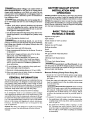
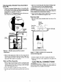
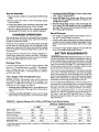
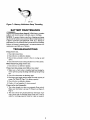
!
SEARS
OWNER'S
MANUAL
Model No.
390.307060
CAUTION:
Read and Follow
All Safety Rulesand
Operating Instructions
Before FirstUse of
ThisProduct.
I:RRFTSMRN°
BATTERY OPERATED
BACKUP SUMP PUMP
• Safety Instructions
Save ThisManual For
Future Reference.
• Operation
• Installation
• Troubleshooting
• Repair Parts
Sears, Roebuck and Co., Haffman Estates, IL 60179
PRINTED
IN
USA
U.S.A.
Form No
F642-9901
(Rev 4/19/04)
CONTENTS
Introduction/Warranty
........................................................
2
IMPORTANT
SAFETY INSTRUCTIONS for BATTERY CHARGER
[AWARNING] Risk of electrical shock, fire, or explosion. Read all instructions in owner's manual and on
charger, pump, and battery before using battery charger.
Safety ...................................................................................
2
Performance ........................................................................
3
Charger Operation ...............................................................
3
1. Unplug battery charger before attempting any cleaning.
Battery Requirements
4
2. Charge onlyrechargeable
..........................................................
12.volt lead-acid batteries.
4-5
3. Do not let charger get wet.
Electrical ...........................................................................
5-6
Service/Troubleshooting
..................................................
6-7
4. Use only attachments recommended
charger manufacturer.
Repair Parts ..........................................................................
7
Installation/Operation
......................................................
or sold by battery
5. When unplugging charger, grasp plug (not cord) to avoid
risk of damage to cord or plug.
6. Locate cord so that it cannot be stepped on, tripped over,
damaged, stretched, or flooded,
INTRODUCTION
Please take a few minutes to read our instructions before installing your Backup Sump Pump. It wlg help to assure perfect installation and help you avoid needless service
expenses.
7. Do not modify cord or plug.
8. Do not attempt to service charger; it has no user-serviceable parts. If charger is dropped, struck, or otherwise
damaged, replace the charger.
SAVE THESE INSTRUCTIONS
RULES
FOR SAFE INSTALLATION
Carefully read and follow all safety instructions
manual or on pump.
in this
DANGER warns about hazards that will cause
serious personal injury, death or major property damage if
ignored.
about hazards
CAUTION
OPERATION
]CAUTION warns about hazards that will or can
cause minor personal injury or property damage if ignored.
_This
is the safety alert symbol. When you see this
symbol on your pump or in this manual, look for one of the
following signal words and be alert to the potential for personal injury!
[AWARNING]WARN1NG warns
I_
AND
that can
cause serious personal injury, death or major property damage if ignored.
The word NOTICE indicates special instructions which are
important but not related to hazards.
l.To avoid risk of serious bodily injury due to electrical
shock or burns and property damage due to flooding, read
the safety instructions carefully before installing pump.
IAWARNINGJBattery acid is corrosive. Do not spill on
skin, clothing, or battery charger. Wear eye and head
protection when working with battery. Connect and disconnect DC output termianls only after removing the
charger from the AC outlet. Never allow the DC terminals to
touch each other.
BATTERY BACKUP SYSTEM
INSTALLATION
AND
OPERATION
[_, WARNINGIHazardous voltage. Can cause severe or
fatal electrical shock. Do not plug in or unplug battery
charger while standing on a wet floor or in water. Be sure
one hand is free when plugging in or unplugging charger. If
basement
floor is wet,
fore walking on floor.
p
disconnect
power
to basement
be-
i
1_, CAUTION ]Risk of flooding.
Do not run pump dry. To
do so will damage seals and can cause leaking and property
damage.
2.Follow
local and/or
national
plumbing
and electrical
codes when installing the system. A ground fault circuit
interrupter
(GFCI) is recommended
for use on any electrical appliance
submerged
in water.
3. Use this system only for backup sump
idential application.
It is not designed
pump.
4. Do not lift pump
_RNINGIRisk
by electrical
clear water
6. Pump is permanently
to lubricate it!
Sill>joint
shock.
Do not
lift the
at the factory.
Do not try
keep sparks
9. Maximum
is 15 feet (4.6M).
pumping
distance
battery
charger
the
INFORMATION
dry and protected
from damage.
In an emergency
(such as an extended
pnwer
outage)
which depletes the system's deep cycle marine battery, your
automobile
battery may be temporarily
substituted.
Be sure
to replace the deep cycle marine battery as soon as possible.
Use of an automobile
battery instead of a deep cycle marine
battery in this system will significantly
reduce system performance.
Automobile
batteries
arc not designed
for this
type of application.
NOTICE: This unit is not designed for applications
involving
salt water or brine! Use with salt water or brine will void
warranty.
or 5/16"
nut driver
(to cut PVC pipe)
size pliers
Pencil
tape
weld)
and primer
Cycle Marine
Battery
Cycle Marine
Battery
LAWARNINGJ Personal injury and flood hazard.
Do not
turn the pump on until all the fittings are glued and the glue
has dried. Loose fittings can explode off the pipes and cause
personal injury and flooding.
The Battery Back-up Sump System is not a substitute
for your
primary sump pump. It is designed
to temporarily
back up
your primary sump pump during a power
outage or other
problem
which prevents
normal operation
of the primary
pump. Do not use this system to pump flammable liquids or
chemicals.
Pump clear water only with this pump.
Keep
Hacksaw
24M Deep
or a
27M Deep
and
10. Make sure sump is clear of debris. Debris can damage
pump which can result in flooding.
GENERAL
wrench
PVC glue (solvent
Cloth towel
7. Keep battery charger and battery box off of the floor
and in a dry, cool, well ventilated
area.
NOTICE: If a Carbon Monoxide
(CO) sensor is installed, it must be at least 15 feet away from battery
charger in order to avoid nuisance
CO alarms. Please
refer to your CO detector's
installation
guidelines
for
more information.
vertical
Socket
Side cutters
Teflon
8. To avoid danger of fire or explosion,
flame (pilot fight) away from battery.
or large pliers
measure
Medium
only with this pump.
lubricated
BASIC TOOLS AND
MATERIALS NEEDED
Tape
pump by the electrical cord; lift pump only by the discharge
pipe, lifting ring or handle on the pump. Lifting by the cord
can damage the cord.
5.Pump
NOTICE:
Be prepared
for water to leak from the coupling
or piping when disassembling
or cutting the discharge pipe.
Protect system components,
tools and supplies from getting
wet. Dry any work areas that get wet.
pump duty in a resas a primary sump
cord.
of electrical
NOTICE: Install this system during a time when the primary
pump will not be needed.
Gather all supplies before starting. Read all warnings and installation steps before you start.
Remove
Primary
Pump
From
Sump
Pit:
1.Locate the "on" water level of the primary sump pump.
Mark this location on the discharge
pipe with a pencil.
See Figure 1.
2. Drain the sump and unplug the pump. The water level
must be pumped
down as low as possible before going
on to the next step.
I& WARNINGJElectrical
i
shock
hazard.
Shock can bum
or kill. Do not make contact with the remaining
water in
the sump pit. Unplug the primary sump pump and any
accessories
such as alarms before you continue.
Failure
to follow this warning
can result in personal
injury or
death.
3. To separate
the primary
pump from the discharge
A. For applications
with rubber couplings:
remove
coupling
clamp with a nut driver, and be prepared
water to spill out.
pipe:
the
for
B. For applications
without
rnbber couplings:
cut the
PVC discharge
pipe with a hacksaw above the basement floor and at a comfortable
level. Be prepared
for
water to spill out. New rubber couplings are included
for reassembly.
[A CAUTION] Risk of pinching
hands or fingers.
a band injury from a collapse of plumbing, support
5. Hold the coupling
(Key No. 6, Page 9) with the channel
locks, insert the screwdriver
into the tee for leverage and
tighten the tee with the screwdriver.
Finish with the tee
in a straight up and down (vertical) position.
To avoid
the pipe
above the separation before cutting or disassembly.
4. Lift the primary pump and discharge pipe assembly out
of the sump.
[AWARNINGIRLsk of electrical
shock.
6. Clean the pipe ends with the cloth
7. Glue the cut-off piece of discharge
pipe into the top of
the tee. If your pipe is 1-1/4", you will need to glue the
reducer bushings into the tee and glue the pipe into the
bushings. Place the assembly on to the primary discharge
pipe. Do not glue the tee onto the Primary Pump discharge pipe.
Do not lift the
pump by the electrical cord; lift pump only by the discharge
pipe, lifting ring or handle on the pump. Lifting by the cord
can damage the cord.
NOTICE: The discharge
water from the discharge
pipe is filled with water. Drain the
pipe assembly. Keep the work area
8.Mount the float switch assembly
(Key No. 9, Page 9)
loosely to the discharge pipe with the cable ties (Key Nos.
9A & 9B, Page 9). Approximately
3 "(76ram) of cord length
should
be left between
the float and the clamp.
Adjustments
may be needed, do not tighten the cable ties.
See Figure 3, Page 5.
dry.
Support the
Pipe before
cutting.
Remove the
hose coupling
or mark the
1st cut here.--_
towel.
Backup Pump and
Check Valve
Assembly
Notto Scale
Switches
First Cut: .......
o
and
Basement
Sump
Pit
'Turn on'
water level of
Primary Pump
Valve
•"---Sump
Reducer
Bushing
Pit
Tee
Figure
Coupling/Check
Valve Assembly
Short End
Faces Tee Long End
Faces Pump
Cut-Off piece of
discharge pipe.
--
I - Mark and cut the pipe as shown
INSTALL
BACKUP
Refer to the Exploded
Key Numbers
View
Reducer
Bushing
PUMP
Pdmary Check
Valve to Prevent
on Page 9 for
Figure 2 - Make the second cut for installation
of the backup pump and check valve assembly.
of the close nipple (Key No. 5, Page 9)
with 2 turns of teflon tape and set
Install the backup pump. Your installation
not require the reducer bushings.
NOTICE: There must be a check valve installed
in the
Primary Sump Pump discharge
between
the tee and the
Primary Sump Pump. This will prevent recirculation
into
the Primary Pump when the Back Up Sump Pump comes
on. See Figure 2.
Installation
Sump Pit:
the tee (Key No. 3, Page 9) into the close
may
of Double Pump Assembly in
1. Put the double
pump
NOTICE: The discharge
pipe leading outside.
3.The backup pump (Key No. 7, Page 9) and coupling
and
check valve assembly
(Key No. 6, Page 9) come preassembled.
Thread the close pipe nipple into the check
valve and pump assembly.
4. Thread
Pipe
Backup
Sump
Pump
into Suing
1.Make a second cut in the discharge
pipe at the pencil
mark made in step 1 and set the cut-off piece of discharge
pipe aside. See Figure 2.
2. Wrap the threads
counterclockwise
aside.
Discharge
assembly
back into the sump pit.
pipe now overlaps
the discharge
2.Mark the discharge pipe where it should be cut. Be sure
to leave a 1/4" air gap between the ends of the pipes. This
gap will absorb noise from vibration
and allow for flexiI_flity. See Figure 4, Page 5.
nipple.
4
Trial Assembly of Double
Sump
4.Take the tee assembly off of the primary discharge pipe.
Do not take the tee off of the threaded assembly.
Pump Assembly in
Pit:
5. Clean an the PVC pipe ends with the PVC cleaner.
1. Connect
the pump discharge
pipe to the exterior discharge pipe with the rubber coupling and clamp kit (Key
No. 2, Page 9). Do not tighten the clamps until all the final
adjustments
are complete.
See Figure 3.
NOTICE: For 1-1/2" discharge pipe, remove
tion of hose from the rubber coupling.
[AWARNING]Hazardous
fumes. Follow the cement and
cleaner manufacturers instructions. Use the PVC cement in
a well ventilated area away from fire or flames.
the inner sec-
6.Glue the PVC fittings where indicated by the pencil
marks. Wait 10 minutes for the glue to cure.
Final Assembly:
1.Put the double pump assembly back into the pit. See
Figure 4.
Excess
discharge
Third Cut:
Cut out
pipe
"xx
_:---"-_-_---'
t
, ,
i
i
overlap
Grounded
Electdoat
Outlet
pit s 114" --_
i
i
,
,
enor dtscharge
pipe
Hose Coupling
with
7" Min.
(178mm)
(305mm)
12" Min.
'Check
Valve
Check
_'Valve
35461099SRS
Figure 3 - Double
installation
pump and float switch
Figure 4 - Make a third cut to remove
excess discharge pipe
2. Make the final adjustments.
switches
do not interfere
Make sure the pumps and the
with each other. Make sure
there is plenty of room for the float switches
from their .off., to their "on" positions.
Mark
and
Glue
2. Loosen
3. Carefully
pit.
the rubber
2. Install
to swing
ELECTRICAL
fittings at all the connections
with
will be used as a reassembly
guide
that everything
is still in the right
moved.
coupling
pull the double
and tighten
and clamp
pump
assembly
the rubber
3. Make the final float switch
cable ties.
Assembly:
1. Mark the pipe and the
a pencil. These marks
while gluing to be sure
place and nothing has
the
coupling
adjustments
and clamp
and tighten
back out of the
5
the
CONNECTIONS
E&WARNING]Hazardous
voltage.
Can cause
fatal electrical shock. Review safety instructions
erating charge. Do not modify cord or plug.
connection.
kit.
serious
before
or
op-
CHARGER/BATTERY
INSTALLATION
4. With the charger properly connected and plugged in, the
panel on the front of the charger will show one of the following conditions (See Figure 6).
NOTICE: An alarm, located in the junction box, automaticall)" sounds when the system runs if the alarm is in the
"Enable" position. The alarm is silenced when the alarm
switch is in the "Disable" position.
LApply two pieces of two-sided tape (provided, Key No.
11, Page 9) to the back of thejuoction box. Press thejuncUon box onto the battery box as illustrated in Figure 5
(below) and on Page 9 (Exploded View).
Continuous REE
2.Connect the charger as shown in Table I and Figure 5.
RaMll_lg Yellow LED
Battery pre-qualificagon
is underway,
test
BaKer
Continuous
Charger
RED LE[
has powen
Continuous Yellow LED
Charger is charging battery.
Continuous
Charger
RED LED
has power.
Green LED
Battery is fully charge(
and ready for use.
Figure 5 - Wiring
Connections
3. Plug the charger into
at least 15 amps. Do
let. Mark circuit in
pump power supply;
a 115-120 Volt AC outlet delivering
not use a switch controlled
outmain power
panel "Backup
sump
do not turn off'.
Ra_i_
Fault indicator.
See the'Error
Charge Table',
Table II.
Figure 6 - LED Panel
TABLE I - Wiring
Connect
Positive
Negative
Positive
Negative
Backup
(+) lead from the battery
(-) lead from the battery
lead from the charger
lead from the charger
sump
float switch
Positive
Negative
Connections
the
pump
(2 wires)
lead from the pump
lead from the pump
To the
Junction
Positive
battery
Negative
Positive
Negative
Box's
battery
connection
charger
connection
charger
TABLE II - Error
connection
Flashing
connection
Positive
Negative
-
A. Charger
C. Charging
(2 wires)
pump
pump
battery
connection
Table
output
lead
connections
has failed
process
maybe
the
pre qualification
has stopped.
6
A new
needed.
D. Battery terminal
voltage
Need new battery.
connection
are
reversed.
B. Battery
Float switch
connection
Red
"Fault" LED:
Charge
is too
low,
tesL
3. Continuous Yellow LED llglht: C0nstant voltage charge
stage. Cells are being equalized.
Test the Assembly:
1. Plug the primary pump into a properly grounded
outlet.
2.FLU the sump with water
Check for leaks.
3-prong
to start the primary
4. Green LED light: Roat charge stage. Battery terminal
voltage has been regulated and system is ready for use.
Charging has stopped.
pump.
5. Recycle charge stage. Charger will automatically initiate a charge cycle that begins with the prequallflcation
test stage. This occurs once the battery has been in the
float charge stage for 28 days.
3. Unplug the primary pump and fig the sump with water
to start the backup system pump. Check for leaks.
4. Plug the primary pump back into a properly grounded
3-prong outlet. The system is now ready for operation.
CHARGER
Special
OPERATION
The backup pump will activate
will sound when the backup
enough to trip the float switch.
automatically
sump water
and an alarm
level rises far
• A built-in safety timer starts when the charger enters the
Constant Current/Constant Voltage Charge stage (Yellow
LEDis continuously on). The system has a 70 hour safety
timer.
If the power to the charger circuit is interrupted,
the length
of time that the backup
pump will run depends
on the
Ampere-hour
capacity of the battery used, the battery charge
level, the required
vertical pumping
distance,
and the size
of the sump.
• To reset the charger simply unplug it from the 120V outlet for 10 seconds and then plug it back in.
BATTERY
Extended
periods of operation
(for example,
during an extended power outage) may exhaust the battery. The battery
charger will begin charging the battery as long as the battery
has a voltage differential
of 3 Volts or more.
Recharge
I '_'WARNING ]Hazardous
Time:
5 Stages of the Charging
Process:
with
Can cause se-
Use only the recommended
battery or one of the same type
and size so it will fit in the battery box (maximum
size 125/8" long, 7" wide and 9-3/8" high [320.7mm
x 177.8mm x
238mm] including terminals) and supply enough voltage for
full performance.
Continuous
Yellow LED light: Constant current charge
stage. Charger is charging battery at the full rated output.
Ratings
current.
Use of a standard automobile
battery with this charger is not
recommended.
An automobile
battery may require charging
after only 1-2 hours of continuous
use, and the repeated
charging cycles may cause early plate failure in the battery.
1. Flashing yellow LED light: Battery prequalification test
stage. Normal duration of this stage is from 40 seconds to
3 hours.
TABLE IlI - Capacity
electrical
Your backup sump pump depends on the battery used with
it for power. The better the battery, the better the performance of the pump. We recommend
the use of a size 27M
Deep Cycle Marine Battery or a size 24M Deep Cycle Marine
Battery. They will perform as indicated
in Table III, below,
and stand up well to long periods of little or no use.
NOTICE: All LED's will illuminate once the AC power has
been applied. They will not light up if the charger is not
plugged in. The RED LED will remain on continuously to indicate power to the charger. See Figure 6.
2.
REQUIREMENTS
vere burns and start a fire if battery terminals are short circuited. Install battery in a battery box (See Key No. 10, Page
9). To prevent accidental
shorting across battery terminals.
strap cover securely (See Figure 7) on the battery box. Do
not leave battery uncovered.
Do not allow children to play
around the battery backup system installation.
It will take approximately 43 hours to fully recharge a 24M
battery in a "discharged battery condition". The approximate recharge time for the 27M battery is 58 hours.
Industrial standards define a "discharged battery condition"
as 10.5 Volts or less.
The
Features:
• The charger is equipped with reverse battery, short circuit, and "run-away charge" protection.
a 24M or 27M Deep
Cycle
Marine
Battery
VERTICAL PUMPING DISTANCE
8 FEET
10 FEET
12 FEET
Battery Size
27M
24M
27M
24M
27M
24M
Gallons Per Minute
18.0
18.0
14.5
14.5
11.5
11.5
Hours Available
12.0
9.5
13.5
10.5
14.5
11.5
Total Gallons Pumped
10,520
8,402
10,422
8,339
5,876
4,516
Recharge Time
56.0
43.0
56.0
43.0
56.0
43.0
* These flow rates were obtained with a constant 12.7 VDC battery source. The average GPH will vary due to a reduction in output
voltage from battery.
Figure 7 - Battery
Hold-down
Strap Threading
BATTERY MAINTENANCE
[_,WARNING ] Severe
sulfuric
acid. Avoid
burn
contact
hazard.
A filled battery
contains
with skin, eyes or clothing.
NOTICE: To protect battery ease from chipping and gouging, do not let battery sit on concrete
floor. Install battery on
a shelf or protective
pad (plywood,
2x4s, etc.). Always install battery in a dry location that is protected
from flooding.
Follow the battery
manufacturer's
maintenance
and safe use of battery.
recommendations
for
TROUBLESHOOTING
Pump won't run.
1. Check all connections.
2. Check for low or defective battery.
3. Check that automatic switch is free to swing up and
down.
4. Check for blown fuse in the junction box of the system.
Motor hums but pump won't run:
1. Check for low or defective battery.
Pump runs but pumps very little or no water:
1. Make sure a check valve is installed and functioning between primary pump discharge and Backup Sump Pump
tee.
2. Check for obstruction in discharge pipe.
3. Discharge pipe length and/or height exceeds capacity of
pump. See Table III, Page 7, for pump capacity.
4. Check for low or defective battery.
5. Positive (+) and negative (-) w'tres reversed.
Pump cycles ton frequently:
1. The tether length too short on automatic float switch.
Make sure that tether is at least 3" (76mm); see Figure 3,
Page 5.
2. The main check valve located between discharge of primary pump and the Backup Sump Pump tee is not instailed or working properly. Install or repair as required.
8
Craftsman Battery Backup Sump Pump
Model 390.307060
I
_1
9A 9B
I
I
I
I
i//
12
3465
0799 SRS
REPAIR PARTS LIST
Key No.
1
2
3
4
5
6
7
8
9
9A
9B
10
11
12
13
14
Part No.
U74-72
U74-68
U78-846P
U78-876P
U37-66P
ZB902110
PS17-118
PS117-120P
PS17-100
PS97-5
PS17-113
PS217-130
PSl17-114
Part Description
Hose Insert
Rubber Hose Coupling and Clamps
PVC Tee 1-1/2 x 1-1/2 Slip x 1-1/4 FNPTW/1-1/4
Reducer Bushing (Requires 2)
PVC Pipe Nipple, 1-1/4 NPT x Close
Coupling, 1-1/4 FNPT x 1-1/4 FNPT and Check Valve Assembly
DC Backup Pump
Replacement Fuse, - ATO 20 Amp, 12 Volt
Float Switch - 1/2HP, 8', 16 Gauge
Small Cable Ties (2)
Large Cable Tie
Battery Case (Complete with Strap)
Two Face Tape, 1" x 2" (t)(Requires 2)
Junction box
Charger Kit (includes wires)
Battery Leads (1 Pair)
t Included in Fittings Package.
* Standard Hardware Item; can be purchased locally.
lO
11
SEARS
OWNER'S
MANUAL
CRAFTSMAN°
BATTERY OPERATED
BACKUP SUMP PUMP
Model No.
390.307060
For the repair or replacementpartsyou need
Call7 am - 7 pro, 7 days a week
1-800-366-PART
(1-800-366-7278)
Foris-homemajorbrandrepairservice
Call24 hoursa day,7 daysa week
The model number of
your Backup Sump Pump
will be located on the
pump, not the battery
charger.
When requesting service
or ordering parts, always
give the following
information:
• Product Type
• Model Number
• Part Number
• Part Description
t -8OO-4-REPAIR
(1-800-473-7247)
Forthe locationof a
SearsRepairServiceCenterin yourarea
Call24 hours a day,7 days a week
1-800-488-1222
Forinformationonpurchasinga Sears
MaintenanceAgreementor to inquire
aboutan existingAgreement
call 9 am - 5 prn, Monday-Saturday
A
1-800-827-6655
SEARS
America_
Repair Specialists
Sears, Roebuck and Co., Hoffman Estates, IL 60179
U.S.A.