1
14797 • November 2004 • Communications Interface Setup
COMMUNICATIONS INTERFACE SETUP
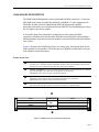
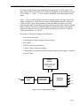
The CI5705 can be used to control operation of modules within the S5000 frame. This
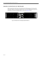
is accomplished via communications through a 9-pin D-subminiature connector located
on the back of the unit labeled NTWK EIA-485. Communications to the S5000 must
adhere to the RS-485 or RS-422 communications protocol.
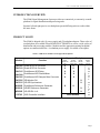
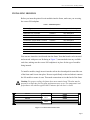
The NTWK EIA-485 connector on the rear of the S5000 utilizes the pinout detailed in
the table which follows.
Table 5. NTWK EIA-485 Pin Assignment
PIN #
FUNCTION
DIRECTION
1
Ground
---
2
Receive A
Output- Rx Data (A)-
3
Transmit B
Input- TxData (B)+
4
Receive Common
---
5
N/C
---
6
Ground
---
7
Receive B
Output- Rx Data (B)+
8
Transmit A
Input- Tx Data (A)-
9
Ground
---
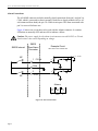
Computers equipped with only RS-232 communications ports will require an RS-232to-RS-422/485 converter like the B&B Electronics model #4WSD9R (http://www.bbelec.com/bb-elec/literature/4WSD9R-3903ds.pdf for more information), or others, to
successfully communicate with the S5000 frame. Carefully check the pinout of the
device you select. If it does not match the above information, an adapter cable may need
to be made.
The CI5705 communications interface needs to have a number of parameters
configured for proper operation when connected to a master controlling device via the
NTWK EIA-485 connector on the rear of the S5000.
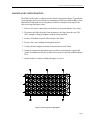
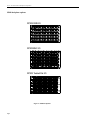
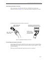
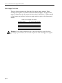
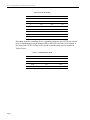
Each frame in the system must have its own identity. The identification code is assigned
to the frame using the first three DIP switches (SW1,SW2 and SW3) of S2 located at
the front of the CI5705 card. The following table indicates the settings required for each
Frame ID.
Page 17