1
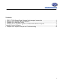
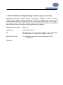
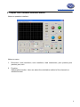
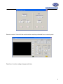
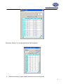
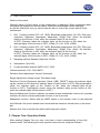
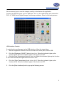
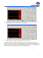
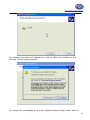
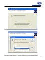
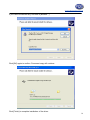
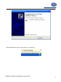
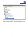
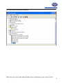
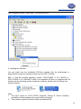
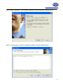
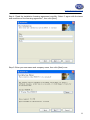
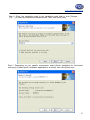
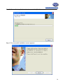
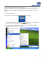
www.pce-industrial-needs.com Tursdale Technical Services Ltd Unit N12B Tursdale Business Park Co. Durham DH6 5PG United Kingdom Phone: +44 ( 0 ) 191 377 3398 Fax: +44 ( 0 ) 191 377 3357 [email protected] http://www.industrial-needs.com/ Manual Oscilloscopes PCE-UT 2000 Series [email protected] Contents: 1. PCE-UT 2000 Series Digital Storage Oscilloscopes Introduction ........................................ 3 2. Chapter One: Software Structure Basics ............................................................................. 4 3. Chapter Two: Operation Guide ............................................................................................ 7 4. Chapter Three: Installation guide for PCE-UT2000 Series Computer................................ 11 Testing & Control Software .................................................................................................... 11 5. Chapter Four: System Prompts and Troubleshooting ........................................................ 26 2 [email protected] 1. PCE-UT 2000 Series Digital Storage Oscilloscopes Introduction The PCE-UT 2000 Series Digital Storage Oscilloscope software is written for PCEUT2000 Series digital storage oscilloscopes. With this software you can carry out communication between a computer and an oscilloscope through serial or USB, and in turn perform remote control. This software also provides testing, waveform and sampling data reading functions to facilitate further signal testing and analysis. Equipment Requirement Minimum Oscilloscope PCE-UT2000 Series PC IBM-compatible PC, Windows 2000/XP OS, 16MB RAM, 4X optical drive or better SVGA display or better RS-232 Power Cord The connection terminals of the oscilloscope and PC must match USB Lead 3 [email protected] 2. Chapter One: Software Structure Basics Notes on operation interface Notes on menu: 1. Document: Load waveform, save waveform, load intersection, print preview, print preview, print, exit. 2. Function: Mathematics function: User can select the calculation method of the channels or window function. 4 [email protected] Remote control: Control of the serial interface can be performed from a remote point. Data form: How the voltage changes with time 5 [email protected] Parameter testing: The current parameters are displayed 3. Refresh waveform: single refresh; waveform time interval setup 6 [email protected] 4. Help: Content; About Notes on front panel Channel status: Current status of the oscilloscope is displayed. When transmitting data, this status bar displays the current status. When the oscilloscope’s status changes, so will this status bar, but you cannot use this bar to control the current status of the oscilloscope. 1. CH1: Coupling method (DC, AC, GND); Bandwidth suppression (On Off); Filter type (low-pass, high-pass, band-pass, band-stop); Digital filter (when the indicator lights up the function is ON, when the indicator lights off the function is OFF); Reverse (when the indicator lights up the function is ON, when the indicator lights off the function is OFF); Probe (1X, 10X, 100X, 1000X). 2. CH2: Coupling method (DC, AC, GND); Bandwidth suppression (On Off); Filter type (low-pass, high-pass, band-pass, band-stop); Digital filter (when the indicator lights up the function is ON, when the indicator lights off the function is OFF); Reverse (when the indicator lights up the function is ON, when the indicator lights off the function is OFF); Probe (1X, 10X, 100X, 1000X). 3. Sampling method; Random; Real-time; SCAN 4. Interpolation (Yes, NO) 5. Current activated channel (MATH; CH1; CH2) Channel selection: CH1; CH2; MATH Deviation factor adjustment: Vertical; Horizontal Range adjustment: Voltage range; Time base range Real-time Control: Equipment selection (Serial, USB); ON/OFF (when the indicator lights up the function is ON, when the indicator lights off the function is OFF); Data transmission (when the indicator lights up the function is ON, when the indicator lights off the function is OFF); Transmission screen (when the indicator lights up the function is ON, when the indicator lights off the function is OFF). Reverse Mathematic function: Indicator on means reverse mathematic function is in process. Indicator off means reverse mathematic function is not in process. Mathematic function: Select with the MATH option in the function menu in the menu bar. Auto Refresh: Set up the refresh time interval with the waveform refresh menu in the menu bar. Refresh time: Set up refresh time while performing auto refresh. 3. Chapter Two: Operation Guide After reading Chapter One you may now have a basic understanding of how this system works. The following are more specific instructions for using the software. 7 [email protected] We recommend you to read this chapter carefully to familiarize with application. Connect the RS-232 power cord or USB lead. Turn on the oscilloscope and activate the P C E - UT 2000 Series Digital Storage Oscilloscope software. Enter the following screen: USB Interface Controls If controlling the oscilloscope via the USB interface, follow the steps below: 1. With the equipment selection knob on the real-time control panel, select USB. 2. Click the [Equipment ON/OFF] knob to turn it on. When the indicator lights up the function is ON. When the indicator lights off the function is OFF. 3. Click the [Data Transmission] knob to turn it on. When the indicator lights up the function is ON. When the indicator lights off the function is OFF. 4. Click the [Data Transmission] knob to turn it off. When the indicator lights up the function is ON. When the indicator lights off the function is OFF. 5. Click the [Data Interface] knob to pop up the following screen. 8 [email protected] 6. Click Series on the above screen so the oscilloscope can transmit continuously as indicated below. You can now control the oscilloscope. 7. When operation is complete press [CLOSE] to close this screen. Note: When starting step 5 after completing step 4, you can select [Function] and then [Remote Control] in the menu bar instead of clicking [Data Interface]. The following screen will pop up to allow control of the oscilloscope but no waveform is displayed. This operation is similar to “Serial Interface Controls” explained below. 9 [email protected] Serial Interface Controls Follow the following steps: 1. Select Serial with the equipment selection knob of the real-time control panel. The following screen appears: Press OK. 2. Click the [Equipment ON/OFF] knob to turn it on. When the indicator lights up the function is ON. When the indicator lights off the function is OFF. 3. Click the [Data Transmission] knob to turn it on. When the indicator lights up the function is ON. When the indicator lights off the function is OFF. Note: This process may take several seconds. 4. Click the [Function] knob on the menu bar than select remote control. The following screen will appear. You can now control the oscilloscope. 10 [email protected] Important: The above screen will not display waveform. Operation of this screen will be indicated in the oscilloscope. 5. At the end of operation press [CLOSE] to close this screen. To switch to USB connection follows the steps for USB connection stated above. When you have finished all operations, press [CLOSE] to switch off the PCE-UT2000 Series Digital Storage Oscilloscope software, then power off the oscilloscope and disconnect the USB lead and RS-232 power cord. 4. Chapter Three: Installation guide for PCE-UT2000 Series Computer Testing & Control Software 1. Hardware There are one USB device communication port and one RS-232 communication port for computer connection on the rear panel of the PCE-UT2000 Series digital storage oscilloscope. By connecting a host (computer or control computer) to any one of the two ports, you can control the oscilloscope with the host from a remote location. 2. Installing the driver Take the USB A-B lead. Connect one end to the USB terminal of the host, and the other end to the USB Device terminal on the rear panel of the oscilloscope. Power on the oscilloscope and turn on the oscilloscope’s power. “Found New Hardware” will appear at the right bottom corner of the operating screen of the host, as shown below: 11 [email protected] You will also see an icon prompt that says “Found New hardware – PCE- UT2000 Series Digital Storage Oscilloscope”. A “Found New hardware” dialogue box will pop up in a little while, as shown below: Set up as follows: Step 1: Select [Yes, this time only] and click [Next] once. Step 2: In the “Found New hardware Wizard” wizard select [Install from a list or specific location (Advanced)], then click [Next]. 12 [email protected] The following screen will appear. Select [Browse]. In the popped up [Browse Folder] box, select the DSO directory in the directory where you intend to install PCE-UT2000, then click [Next]. (As shown below). Step 3: Enter the search-in-progress waiting screen. 13 [email protected] The dialogue box below will appear but it will not affect the software or your computer. Click [Continue Anyway]. The system will automatically jump to the [System Restore Setup] screen and the 14 [email protected] document is copied. The following screen will appear while the document is being copied. Click the left arrow of [Browse…] to select the directory you have defined in Step 2. 15 [email protected] If you have not defined any, find one in [Browse…]. Click [OK] again to confirm. Document copy will continue. Click [Finish] to complete installation of the driver. 16 [email protected] At the right bottom corner of the screen, you will see: Display of the [Device Manager] is as follows: 17 [email protected] Note: If no [Found New Hardware] wizard pops up on your computer screen when the computer is properly connected to the oscilloscope and the latter is powered on normally, right click [My Computer] and select [Attribute]. In the [System Attribute] dialogue box select the [Hardware] box. Click the [Device Manager] button. In the pop up [Device Manager] dialogue box, you can see a yellow P C E - UT2000 18 [email protected] icon that indicates incomplete installation. Right click your mouse and select [Update Driver Application] to pop up the [Found 19 [email protected] New Hardware] wizard. Follow step 1 to install the driver. 3. Installing the software You can install from the installation CD-Rom supplied with the oscilloscope or download the computer software directly from the UNI-T website. Step 1: Find the suitable operating system “PCE-UT2000 VI (For WinXP) or PCE-UT2000 VI (For Win2000)” folder in the supplied CD-Rom or unzipped path. As directed by the operating system installation software, double click the Setup icon as shown below: Note: 1. The Ultra scope for PCE-UT2000 Computer Testing & Control Software installation kit downloaded online must first be unzipped. 2. This software supports Windows 2000 and Windows XP. 20 [email protected] Step 2: Begin installation. The software installation wizard pops up as shown below : Step 3: Confirm that you wish to install this software. Click the [Next] button. 21 [email protected] Step 4: Read the installation licensing agreement carefully. Select “I agree with the terms and conditions of the licensing agreement”, then click [Next]. Step 5: Enter your user name and company name, then click [Next] once. 22 [email protected] Step 6: Enter the installation path in the installation path field or click [Change ( )H…..] to select an alternative installation path. Then click [Next] once. Step 7: Depending on your specific requirement, select [Quick installation for the current user only] or [Make quick installation applicable to all users], then click [Next] once. 23 [email protected] Step 8: After confirming all information is correct, click [Next] once. Step 9: The successful installation screen appears. 24 [email protected] Step 10: When installation is complete as shown above, click [Finish (F)] once on the screen. The software has been installed in your host. If you wish to change any setup, simply click [Back (B)] once during any stage of the wizard. If you wish to stop the installation, click [Cancel] once during any stage of the wizard to quit. 3. Running the Software There are two ways to find this software and run it on your computer. 1. After finishing installation, a shortcut icon appears on your desktop. Double click this icon to run the computer testing & control software. 2. Alternatively find the software in All Programs (P) in the Start Menu. Select the computer testing & control software and run. 25 [email protected] 5. Chapter Four: System Prompts and Troubleshooting System Prompts Time out prompt: Check the serial configuration or check whether the equipment is properly connected. Time out prompt: Check the USB configuration or check whether the equipment is properly connected. SCAN prompt: SCAN will perform single transmission. Please carry out single refresh. Continue? Are you sure you want to exit Virtual Instrument? A prompt will ask you if you wish to close the software. Troubleshooting 1. If the system prompts you to check serial or USB configuration when you enter [Equipment ON/OFF], take the following steps: Check whether the oscilloscope power plug is properly connected. Check whether oscilloscope ports match the testing and control software setups (Factory default: RS-232 baud rate 4800). Check whether the cable connection between module and PC is in order. After carrying out the above checks, restart the software to continue operation. In this direction will find a vision of the measurement technique: http://www.industrial-needs.com/measuring-instruments.htm NOTE: "This instrument doesn’t have ATEX protection, so it should not be used in potentially explosive atmospheres (powder, flammable gases)." 26