1
Service Manual
Tumble dryer
T5130, T5130C
Type N1130
Service manual in original language
438 9038-30/EN
2012.02.24
Contents
Contents
1 Safety Precautions ............................................................................................................. 5
2 Technical data .................................................................................................................... 7
2.1 Drawing ...................................................................................................................... 7
2.2 Technical data............................................................................................................. 8
2.3 Connections................................................................................................................ 8
3 Machine presentation......................................................................................................... 9
4 Function check ................................................................................................................... 10
5 Sensors and overheating thermostats ............................................................................... 12
5.1 Inlet air........................................................................................................................ 12
5.1.1 Overheating thermostat ...................................................................................... 12
5.1.2 Heating sensor (PT100)...................................................................................... 16
5.2 Outlet air ..................................................................................................................... 17
5.2.1 Overheating thermostat ...................................................................................... 17
5.2.2 Heating sensor (NTC-sensor) ............................................................................. 20
6 Door ................................................................................................................................... 21
6.1 Door switch................................................................................................................. 21
6.2 Reversing the door ..................................................................................................... 23
7 Motor .................................................................................................................................. 25
7.1 Replacement of motor ................................................................................................ 25
7.2 Replacement of the belt around the motor pulley....................................................... 30
7.3 Replacement of fan .................................................................................................... 33
7.4 Replacement of fan motor .......................................................................................... 37
8 Heating unit, electric........................................................................................................... 39
8.1 General....................................................................................................................... 39
8.2 Replacement of heating element................................................................................ 39
9 Drum .................................................................................................................................. 44
9.1 Replacement of drum ................................................................................................. 44
9.2 Replacement of bearing ............................................................................................. 48
9.3 Replacement of the belt around the drum .................................................................. 51
10 Control panel.................................................................................................................... 54
10.1 Program unit ............................................................................................................. 54
10.1.1 Description ........................................................................................................ 54
10.1.2 Connections ...................................................................................................... 55
10.1.3 Replacement of program unit............................................................................ 55
10.2 Control knob ............................................................................................................. 59
10.2.1 Replacement of control knob ............................................................................ 59
11 I/O modules ...................................................................................................................... 62
11.1 General ..................................................................................................................... 62
11.2 Replacement of I/O module ...................................................................................... 64
11.3 External connections to I/O module type 2 ............................................................... 66
11.4 Circuit diagram of function options for I/O module type 2......................................... 67
11.4.1 Central payment (2J)......................................................................................... 67
11.4.2 Central payment (2J)......................................................................................... 68
11.4.3 External coin meter/Central payment (2K) ........................................................ 69
11.4.4 Price reduction (2K) .......................................................................................... 70
12 Troubleshooting................................................................................................................ 71
12.1 General..................................................................................................................... 71
Contents
12.2 Error code................................................................................................................. 72
12.3 Description of error codes and causes ..................................................................... 74
MAIN COMMON .......................................................................................................... 74
MAIN DRYER .............................................................................................................. 75
DRUM MOTOR COMMON .......................................................................................... 82
FAN MOTOR COMMON.............................................................................................. 83
INTERNAL COM.......................................................................................................... 84
EXTERNAL COM. PAYMENT...................................................................................... 85
EXTERNAL COM. CMIS.............................................................................................. 86
13 Maintenance..................................................................................................................... 87
13.1 Clean the fan, the exhaust duct and the fresh-air intake to the room....................... 87
13.2 Clean the glide surface for the RMC graphite collectors .......................................... 87
13.3 Clean the area around the drum............................................................................... 88
13.4 Clean the motor ........................................................................................................ 89
13.5 Check the belt........................................................................................................... 92
The manufacturer reserves the right to make changes to design and component specifications.
Safety Precautions
1 Safety Precautions
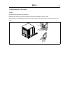
The machine is not intended for use by persons (including children) with reduced physical, sensory or
mental capabilities, or lack of experience and knowledge, unless they have been given supervision or
instruction concerning use of the appliance by a person responsible for their safety.
Children should be supervised to ensure that they do not play with the machine.
The machine is not to be used if industrial chemicals have been used for cleaning.
Do not dry unwashed items in the machine.
Items that have been soiled with substances such as cooking oil, acetone, alcohol, petrol, kerosene, spot
removers, turpentine, waxes and wax removers should be washed in hot water with an extra amount
of detergent before being dried in the machine.
Items such as foam rubber (latex foam), shower caps, waterproof textiles, rubber backed articles and
clothes or pillows fitted with foam rubber pads should not be dried in the machine.
Fabric softeners or similar products should be used as specified by the fabric softener instructions.
The final part of a drying cycle occurs without heat (cool down cycle) to ensure that the items are left at a
temperature that ensures that the items will not be damaged.
Remove all objects from pockets such as lighters and matches.
WARNING. Never stop the machine before the end of the drying cycle unless all items are quickly removed
and spread out so that the heat is dissipated.
Adequate ventilation has to be provided to avoid the back flow of gases into the room for appliances
burning other fuels, including open fires.
Exhaust air must not be discharged into a flue which is used for exhausting fumes from appliances burning
gas or other fuels.
The machine must not be installed behind a lockable door, a sliding door or a door with a hinge on the
opposite side to that of the machine.
If the machine has a lint trap this has to be cleaned frequently.
The lint must not be accumulated around the machine.
DO NOT MODIFY THIS APPLIANCE.
Gas heated tumble dryer:
Before installation, check that the local distribution conditions, nature of gas and pressure and the
adjustment of the appliance are compatible.
The machine is not to be installed in rooms containing cleaning machines with perchloroethylene,
TRICHLOROETHYLENE or CHLOROFLUOROCONTAINING HYDROCARBONS as cleaning agents.
If you can smell gas:
• Do not switch on any equipment
• Do not use electrical switches
• Do not use telephones in the building
• Evacuate the room, building or area
• Contact the person responsible for the machine
5
6
Safety Precautions
All external equipment which is connected to the machine must be CE/EMC-approved and connected using
an approved shielded cable.
In order to prevent damage to the electronics (and other parts) that may occur as the result of condensation,
the machine should be placed in room temperature for 24 hours before being used for the first time.
Servicing shall be carried out only by authorized personnel.
Technical data
7
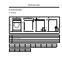
2 Technical data
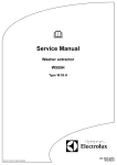
2.1 Drawing
A
E
B
1
E
3
3
D
D
2
C
I
G
5
4
H
F
fig.7250A
1
Operating panel
2
Door opening, ⌀ 370 mm
3
Electrical connection
4
Exhaust connection
5
Condense connection
mm
mm
A
B
C
D
E
F
G
H
595
735
850
80
80
100
200
235
I
J
K
115
300
70
8
Technical data
2.2 Technical data
T5130
T5130C
kg
54
57
litres
130
130
Drum diameter
mm
575
575
Drum depth
mm
500
500
Drum speed
rpm
53
53
0.9
0.9
kg
6
6
kW
5.1
3.0
kW
3.2
dB(A)
70
70
T5130
T5130C
100
—
-
1/2"
Weight, net
Drum volume
G-factor, max.
Rated capacity, filling factor 1:22 (Max. load)
Heating: Electricity
Airborne sound level
2.3 Connections
Air outlet
Condensate outlet
⌀ mm
ISO 7/1–Rp1/2
Machine presentation
9
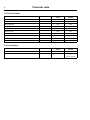
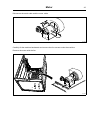
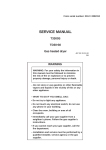
3 Machine presentation
6
5
7
2
1
4
4
3
3
T5130C
T5130
1
1
fig.7552
①
1
Sensors and overheating thermostats
2
Door
3
Motor
4
Heating unit
5
Drum
6
Control panel with program unit
7
I/O modules
After a repair has been made
Whenever a repair has been made, a function check must be performed before the machine can
be used again.
Function check
10
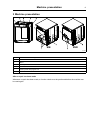
4 Function check
May only be carried out by qualified personnel.
A function check must be made when the installation is finished and before the machine can be
ready to be used.
Check the automatic stop of the machine
• Start the machine.
• Check if the micro switches are working properly:
The machine must stop if the door is opened.
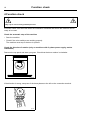
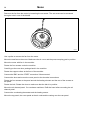
Check the direction of rotation (only on machines with 3–phase power supply, marine
installation)
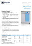
Demount the top panel and start a program. Check that the drum rotation is clockwise.
fig.W00200
②
If the direction is wrong, swop two of the three phases to the left on the connection terminal.
fig.7119
③
Function check
11
Check the heat
• Let the machine work for five minutes on a program with heat.
• Check that the heating is working by opening the door and feel if there is heat in the drum.
Ready to use
If all tests are OK the machine is now ready to be used.
If some of the tests failed, or deficiencies or errors are detected, please contact your local service
organisation or dealer.
12
Sensors and overheating thermostats
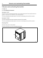
5 Sensors and overheating thermostats
5.1 Inlet air
5.1.1 Overheating thermostat
Description T5130
There are two inlet overheating thermostats. One is placed at the back of the machine and one is
placed on the bottom of the machine on the heating element.
The inlet overheating thermostat opens in the event of overheating and shuts off the machine.
Description T5130C
The inlet overheating thermostat is placed at the back of the machine.
The inlet overheating thermostat opens in the event of overheating and shuts off the machine.
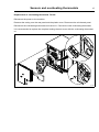
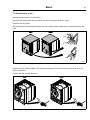
Resetting T5130
Disconnect the power to the machine.
Press the reset button (A) on the overheating thermostat.
A
fig.7585
④
Sensors and overheating thermostats
13
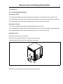
Resetting — T5130C
Disconnect the power to the machine.
Press the reset button (A) on the overheating thermostat.
A
fig.7594
⑤
14
Sensors and overheating thermostats
Replacement of overheating thermostat T5130
Disconnect the power to the machine.
Demount the casing over the rear panel.
Demount the cover panel over the overheating thermostat.
Disconnect the overheating thermostat and remove it. Connect the new overheating thermostat.
fig.7586
⑥
Remount the cover panel over the overheating thermostat and the rear panel.
Sensors and overheating thermostats
15
Replacement of overheating thermostat T5130C
Disconnect the power to the machine.
Demount the casing over the rear panel and the plastic cover. Disconnect the air channel panel.
Disconnect the overheating thermostat and remove it. Connect the new overheating thermostat.
It is recommended to replace the complete heating element cover with the overheating thermostat
on.
fig.7595
⑦
16
Sensors and overheating thermostats
5.1.2 Heating sensor (PT100)
Description
The heating sensor is placed at the back of the machine.
The heating sensor measures the temperature in the inlet air and the signal is returned to the CPU.
The CPU turns the heating unit off when the inlet air thermistor indicates that the required
temperature has been reached.
Replacement of heating sensor (PT100)
Disconnect the power to the machine.
Disconnect the heating sensor and remove it. Connect the new heating sensor and put it in position.
Make sure the sensor gets all the way down.
T5130
T5130C
fig.7588
⑧
Sensors and overheating thermostats
17
5.2 Outlet air
5.2.1 Overheating thermostat
Description T5130
The outlet overheating thermostat is placed on the bottom of the machine on the outlet air flow.
The overheating thermostat ensures that the machine does not overheat during program operation.
The overheating thermostat opens automatically and has to be reset manually.
Description T5130C
The outlet overheating thermostat is placed behind the door switch.
The overheating thermostat ensures that the machine does not overheat during program operation.
The overheating thermostat opens automatically and has to be reset manually.
Resetting T5130
Disconnect the power to the machine.
Demount the rear panel and the cover panel at the air outlet.
Press the reset button (A) on the overheating thermostat.
A
fig.7589
⑨
Remount the cover panel at the air outlet and the rear panel.
18
Sensors and overheating thermostats
Resetting T5130C
Disconnect the power to the machine.
Open the door and demount the door switch.
Press the reset button (A) on the overheating thermostat.
A
fig.7593
⑩
Remount the door switch.
Replacement of overheating thermostat
Disconnect the power to the machine.
Demount the rear panel.
Disconnect the overheating thermostat and remove it. Connect the new overheating thermostat.
fig.7590
⑪
Remount the rear panel.
Sensors and overheating thermostats
19
Replacement of overheating thermostat — T5130C
Disconnect the power to the machine.
Open the door and demount the door switch. Disconnect the overheating thermostat and remove
it. Connect the new overheating thermostat.
fig.7596
⑫
Remount the door switch.
20
Sensors and overheating thermostats
5.2.2 Heating sensor (NTC-sensor)
Description T5130C
The heating sensor is placed next to the outlet overheating thermostat behind the door switch.
The heating sensor measures the temperature in the outlet air and the signal is returned to the PCB.
The PCB turns the heating unit off when the outlet air thermistor indicates that the required
temperature has been reached.
Replacement of heating sensor (NTC-sensor) T5130C
Disconnect the power to the machine.
Open the door and demount the door switch. Disconnect the heating sensor and remove it.
Connect the new heating sensor.
fig.7597
⑬
Remount the door switch.
Door
21
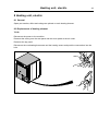
6 Door
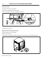
6.1 Door switch
The door switch (A) ensures that the machine stops automatically if the door is opened during
operation.
If the machine does not stop when the door is opened or if the door is closed and the error code
DOOR IS OPEN is displayed (and the machine is unable to start), for example, the door switch
needs to be replaced.
A
fig.W00275
⑭
Replacement of door switch
Disconnect the power to the machine.
Demount the top panel.
Cut the cable tie holding the door switch cable.
Open the door and demount the door switch and the door switch cable and mount the new one.
fig.W00276
⑮
Remount the top panel.
22
Door
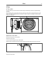
Replacement of door magnets
Remove the magnet to be replaced and mount the new one.
fig.7459
⑯
Door
23
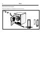
6.2 Reversing the door
Disconnect the power to the machine.
Demount the lower hinge and lift off the door.
Note!
Make sure to hold the door in position when loosening the hinge mounting.
Demount the upper hinge.
fig.W00180A
⑰
Demount the cover screws on the other side and mount them where the hinges was. Mount the
hinges on the other side where the cover screws was. Mount the lower hinge soft, with one screw
first, in order to make it easier to place the door back in position.
fig.W00182A
⑱
Door
24
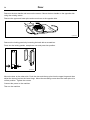
Demount the door handle and remount the screws. Mount the door handle on the opposite side
using the existing scews.
Remove the upper and lower pivot and mount them at the opposite side.
fig.W00183A
⑲
Demount the locking panels by loosening the barb with a screwdriver.
Press out the locking panels, swap them over and press into position.
fig.W00184A
⑳
Mount the door on the other side. Push the door and the top pivot into the upper hinge and then
adjust the lower pivot into the lower hinge. Mount the remaining screw when the lower pivot is in
correct position. Tighten the screws.
Connect the power to the machine.
Test run the machine.
Motor
25
7 Motor
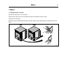
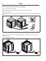
7.1 Replacement of motor
Disconnect the power to the machine.
Demount the casing over the rear panel and the cover panel at the air outlet.
Demount the top panel.
Disconnect the overheating thermostat and the heating sensor and push the connections into the
hole.
T5130
T5130C
fig.7519A
21
Motor
26
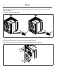
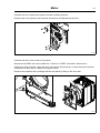
Demount the air channel panel. On condense machines: Pull out the hose to the drain from its
upper connection.
Loosen the belt around the drum.
T5130
T5130C
fig.7522A
22
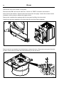
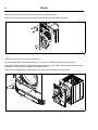
Unscrew the four screws at the panel around the heating element.
Demount the cover panel to the electrical connections and disconnect all wires.
fig.7527
23
Motor
27
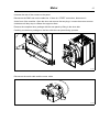
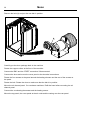
Unscrew the rest of the screws on the panel.
Disconnect the RMC and cut the cable ties. If there is a “FREE” connection, disconnect it.
At the front of the machine: Open the door and remove the two plugs. Loosen the screws counter
clockwise until they stop to release the support rollers.
Remove the complete drum package with the rear panel by lifting in the drum belt.
Carefully put the drum package on the floor witht the rear panel facing upwards.
fig.7531
24
Disconnect the earth cable and the motor cable.
fig.7539
25
28
Motor
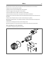
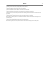
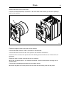
Carefully tilt the machine backwards and remove the four screws under the machine.
Remove the motor with the fan.
fig.7540
26
Demount the fan from the motor by looseing the set screw. The set screw can be accessed through
a hole in one of the blades.
fig.7541
27
Motor
29
Mount the fan on the new motor and mount the new motor with the fan in the machine.
Fasten the four screws under the machine.
Carefully put the new drum package back in the machine.
Fasten the support rollers at the front of the machine.
Connect the RMC and the “FREE” connection if disconnected.
Connect the wires and mount the cover panel to the electrical connections.
Fasten the four screws at the panel around the heating element and the rest of the screws on
the panel.
Fasten the belt. Rotate the drum to make sure that the belt is in position.
Mount the air channel panel. On condense machines: Refit the hose before mounting the air
channel panel.
Connect the overheating thermostat and the heating sensor.
Mount the top panel, the cover panel at the air outlet and the casing over the rear panel.
Other replacing parts on the transmission
It is possible to change single parts by the motor.
fig.500255
28
Motor
30
7.2 Replacement of the belt around the motor pulley
Disconnect the power to the machine.
Demount the casing over the rear panel and the cover panel at the air outlet.
Demount the top panel.
Disconnect the overheating thermostat and the heating sensor and push the connections into the
hole.
T5130
T5130C
fig.7519A
29
Demount the air channel panel. On condense machines: Pull out the hose to the drain from its
upper connection.
Loosen the belt around the drum.
T5130
T5130C
fig.7522A
30
Motor
31
Unscrew the four screws at the panel around the heating element.
Demount the cover panel to the electrical connections and disconnect all wires.
fig.7527
31
Unscrew the rest of the screws on the panel.
Disconnect the RMC and cut the cable ties. If there is a “FREE” connection, disconnect it.
At the front of the machine: Open the door and remove the two plugs. Loosen the screws counter
clockwise until they stop to release the support rollers.
Remove the complete drum package with the rear panel by lifting in the drum belt.
fig.7531
32
32
Motor
Remove the belt (A) and put the new belt in position.
A
fig.7536
33
Carefully put the drum package back in the machine.
Fasten the support rollers at the front of the machine.
Connect the RMC and the “FREE” connection if disconnected.
Connect the wires and mount the cover panel to the electrical connections.
Fasten the four screws at the panel around the heating element and the rest of the screws on
the panel.
Fasten the belt. Rotate the drum to make sure that the belt is in position.
Mount the air channel panel. On condense machines: Refit the hose before mounting the air
channel panel.
Connect the overheating thermostat and the heating sensor.
Mount the top panel, the cover panel at the air outlet and the casing over the rear panel.
Motor
33
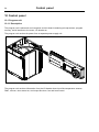
7.3 Replacement of fan
Disconnect the power to the machine.
Demount the casing over the rear panel and the cover panel at the air outlet.
Demount the top panel.
Disconnect the overheating thermostat and the heating sensor and push the connections into the
hole.
T5130
T5130C
fig.7519A
34
Demount the air channel panel. On condense machines: Pull out the hose to the drain from its
upper connection.
Loosen the belt around the drum.
T5130
T5130C
fig.7522A
35
34
Motor
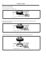
Unscrew the four screws at the panel around the heating element.
Demount the cover panel to the electrical connections and disconnect all wires.
fig.7527
36
Unscrew the rest of the screws on the panel.
Disconnect the RMC and cut the cable ties. If there is a “FREE” connection, disconnect it.
At the front of the machine: Open the door and remove the two plugs. Loosen the screws counter
clockwise until they stop to release the support rollers.
Remove the complete drum package with the rear panel by lifting in the drum belt.
Carefully put the drum package on the floor witht the rear panel facing upwards.
fig.7531
37
Motor
35
Disconnect the earth cable and the motor cable.
fig.7539
38
Carefully tilt the machine backwards and remove the four screws under the machine.
Remove the motor with the fan.
fig.7540
39
36
Motor
Demount the fan from the motor by loosening the set screw. The set screw can be accessed
through a hole in one of the blades.
fig.7541
40
Use a puller to remove the fan from the motor.
Mount the new fan on the motor. Make sure the air cover and the pressure spring gets in position.
Mount the motor with fan in the machine.
Fasten the four screws under the machine.
Carefully put the new drum package back in the machine.
Fasten the support rollers at the front of the machine.
Connect the RMC and the “FREE” connection if disconnected.
Connect the wires and mount the cover panel to the electrical connections.
Fasten the four screws at the panel around the heating element and the rest of the screws on
the panel.
Fasten the belt. Rotate the drum to make sure that the belt is in position.
Mount the air channel panel. On condense machines: Refit the hose before mounting the air
channel panel.
Connect the overheating thermostat and the heating sensor.
Mount the top panel, the cover panel at the air outlet and the casing over the rear panel.
Motor
37
7.4 Replacement of fan motor
T5130C
Disconnect the power to the machine.
Demount the casing over the rear panel and the cover panel at the air outlet.
Disconnect the overheating thermostat and the heating sensor and push the connections into the
hole.
fig.7519D
41
38
Motor
Demount the plastic cover and the air channel panel.
Disconnect the fan motor and replace the fan motor with the new one and connect it.
fig.7599
42
Mount the air channel panel and the plastic cover.
Connect the overheating thermostat and the heating sensor.
Mount the cover panel at the air outlet and the casing over the rear panel.
Heating unit, electric
39
8 Heating unit, electric
8.1 General
Spare part number, effect and voltage are printed on each heating element.
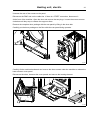
8.2 Replacement of heating element
T5130
Disconnect the power to the machine.
Demount the casing over the rear panel and the cover panel at the air outlet.
Demount the top panel.
Disconnect the overheating thermostat and the heating sensor and push the connections into the
hole.
fig.7519B
43
40
Heating unit, electric
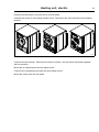
Demount the air channel panel.
Loosen the belt around the drum.
fig.7522C
44
Unscrew the four screws at the panel around the heating element.
Demount the cover panel to the electrical connections and disconnect all wires.
fig.7527
45
Heating unit, electric
41
Unscrew the rest of the screws on the panel.
Disconnect the RMC and cut the cable ties. If there is a “FREE” connection, disconnect it.
At the front of the machine: Open the door and remove the two plugs. Loosen the screws counter
clockwise until they stop to release the support rollers.
Remove the complete drum package with the rear panel by lifting in the drum belt.
Carefully put the drum package on the floor witht the rear panel facing upwards.
fig.7531
46
Carefully tilt the machine backwards and remove the three screws under the machine to release the
lower element cover panel.
Disconnect the wires, demount the cover panels and remove the heating element.
fig.7550
47
42
Heating unit, electric
Connect the new element. Reconnect the wires as before, use the electric schematic supplied
with the machine.
Mount the element unit back in the machine and fasten the three screws under the machine.
Carefully put the drum package back in the machine.
Fasten the support rollers at the front of the machine.
Connect the RMC and the “FREE” connection if disconnected.
Connect the wires and mount the cover panel to the electrical connections.
Fasten the four screws at the panel around the heating element and the rest of the screws on
the panel.
Fasten the belt. Rotate the drum to make sure that the belt is in position.
Mount the air channel panel.
Connect the overheating thermostat and the heating sensor.
Mount the top panel, the cover panel at the air outlet and the casing over the rear panel.
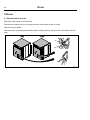
T5130C
Disconnect the power to the machine.
Demount the casing over the rear panel.
Disconnect the overheating thermostat and the heating sensor and push the connections into the
hole.
fig.7519C
48
Heating unit, electric
43
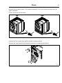
Demount the the plastic cover and the air channel panel.
Unscrew the screws to the heating element cover. Disconnect the wires and remove the heating
element.
fig.7547
49
Connect the new element. Reconnect the wires as before, use the electric schematic supplied
with the machine.
Mount the air channel panel and the plastic cover.
Connect the overheating thermostat and the heating sensor.
Mount the casing over the rear panel.
Drum
44
9 Drum
9.1 Replacement of drum
Disconnect the power to the machine.
Demount the casing over the rear panel and the cover panel at the air outlet.
Demount the top panel.
Disconnect the overheating thermostat and the heating sensor and push the connections into the
hole.
T5130
T5130C
fig.7519A
50
Drum
45
Demount the air channel panel. On condense machines: Pull out the hose to the drain from its
upper connection.
Loosen the belt around the drum.
T5130
T5130C
fig.7522A
51
Unscrew the four screws at the panel around the heating element.
Demount the cover panel to the electrical connections and disconnect all wires.
fig.7527
52
46
Drum
Unscrew the rest of the screws on the panel.
Disconnect the RMC and cut the cable ties. If there is a “FREE” connection, disconnect it.
At the front of the machine: Open the door and remove the two plugs. Loosen the screws counter
clockwise until they stop to release the support rollers.
Remove the complete drum package with the rear panel by lifting in the drum belt.
Carefully put the drum package on the floor witht the rear panel facing upwards.
fig.7531
53
Remove the bolt and washer from the bearing to release the drum. Remove the rear panel from the
old drum. Mount the rear panel with with the bearing on the new drum.
fig.7532
54
Drum
Carefully put the new drum package back in the machine.
Fasten the support rollers at the front of the machine.
Connect the RMC and the “FREE” connection if disconnected.
Connect the wires and mount the cover panel to the electrical connections.
Fasten the four screws at the panel around the heating element and the rest of the screws on
the panel.
Fasten the belt. Rotate the drum to make sure that the belt is in position.
Mount the air channel panel. On condense machines: Refit the hose before mounting the air
channel panel.
Connect the overheating thermostat and the heating sensor.
Mount the top panel, the cover panel at the air outlet and the casing over the rear panel.
47
Drum
48
9.2 Replacement of bearing
Disconnect the power to the machine.
Demount the casing over the rear panel and the cover panel at the air outlet.
Demount the top panel.
Disconnect the overheating thermostat and the heating sensor and push the connections into the
hole.
T5130
T5130C
fig.7519A
55
Demount the air channel panel. On condense machines: Pull out the hose to the drain from its
upper connection.
Loosen the belt around the drum.
T5130
T5130C
fig.7522A
56
Drum
49
Unscrew the four screws at the panel around the heating element.
Demount the cover panel to the electrical connections and disconnect all wires.
fig.7527
57
Unscrew the rest of the screws on the panel.
Disconnect the RMC and cut the cable ties. If there is a “FREE” connection, disconnect it.
At the front of the machine: Open the door and remove the two plugs. Loosen the screws counter
clockwise until they stop to release the support rollers.
Remove the complete drum package with the rear panel by lifting in the drum belt.
Carefully put the drum package on the floor witht the rear panel facing upwards.
fig.7531
58
50
Drum
Remove the screws, bolt and washer on the bearing. Remove the bearing and mount the new one.
fig.7532A
59
Carefully put the new drum package back in the machine.
Fasten the support rollers at the front of the machine.
Connect the RMC and the “FREE” connection if disconnected.
Connect the wires and mount the cover panel to the electrical connections.
Fasten the four screws at the panel around the heating element and the rest of the screws on
the panel.
Fasten the belt. Rotate the drum to make sure that the belt is in position.
Mount the air channel panel. On condense machines: Refit the hose before mounting the air
channel panel.
Connect the overheating thermostat and the heating sensor.
Mount the top panel, the cover panel at the air outlet and the casing over the rear panel.
Drum
51
9.3 Replacement of the belt around the drum
Disconnect the power to the machine.
Demount the casing over the rear panel and the cover panel at the air outlet.
Demount the top panel.
Disconnect the overheating thermostat and the heating sensor and push the connections into the
hole.
T5130
T5130C
fig.7519A
60
Demount the air channel panel. On condense machines: Pull out the hose to the drain from its
upper connection.
Loosen the belt around the drum (A).
T5130
T5130C
A
A
fig.7522B
61
52
Drum
Unscrew the four screws at the panel around the heating element.
Demount the cover panel to the electrical connections and disconnect all wires.
fig.7527
62
Unscrew the rest of the screws on the panel.
Disconnect the RMC and cut the cable ties. If there is a “FREE” connection, disconnect it.
At the front of the machine: Open the door and remove the two plugs. Loosen the screws counter
clockwise until they stop to release the support rollers.
Remove the complete drum package with the rear panel by lifting in the drum belt.
fig.7531
63
Drum
53
Remove the belt from the outer drum.
Put the new belt temporarely in position on the outer drum and carefully put the drum package
back in the machine.
A
fig.7538
64
Fasten the support rollers at the front of the machine.
Connect the RMC and the “FREE” connection if disconnected.
Connect the wires and mount the cover panel to the electrical connections.
Fasten the four screws at the panel around the heating element and the rest of the screws on
the panel.
Rotate the drum to make sure that the belt is in position.
Mount the air channel panel. On condense machines: Refit the hose before mounting the air
channel panel.
Connect the overheating thermostat and the heating sensor.
Mount the top panel, the cover panel at the air outlet and the casing over the rear panel.
54
Control panel
10 Control panel
10.1 Program unit
10.1.1 Description
The program unit is electronic and comprises a circuit board containing microprocessor, program
memory, serial interface to the motor, I/O boards etc.
The program unit receives its power from a separate power supply unit.
fig.7553
65
The program unit receives information from the I/O boards about input like temperature sensors,
RMC, vacuum, door status etc, and output like drum, fan and heat control.
Control panel
55
10.1.2 Connections
The program unit board has the following connections:
Board connector
Function
M-COM
Communication, motor control (not used)
D-BUS
Databus
D-BUS
Databus
TACHO
Tachometer (not used)
COIN
Coin meter (coin 1, coin 2, blocking)
EMERG / INP 1
Input
FREE / INP 2
Free program (key switch) / Input
RS 232
Serial communication
ENC
Control knob (pulses)
USB TYPE B
Connection for software / service download
PIN CONNECTOR
Panel sign connector
fig.W00283
66
10.1.3 Replacement of program unit
Disconnect the power to the machine.
Demount the top panel.
56
Control panel
Demount the control knob
Insert a screwdriver in the upper hole.
fig.7491
67
Gently push the screwdriver inwards and turn the control knob counter-clockwise until the
screwdriver goes further in.
fig.7492
68
Continue turning a quarter of a turn until it is possible to remove the control knob.
fig.7493
69
Control panel
57
Demount the cover ring
When the control knob is removed, insert the screwdriver in the lower hole and press gently. Turn
the cover ring counter-clockwise until it is possible to remove the cover ring.
fig.7490
70
Demount the program unit
Demount the CPU and disconnect the cables.
fig.7553
71
Control panel
58
Mount the new program unit
Mount the new CPU. Make sure that the guide pins (A) are in position.
A
fig.7511
72
Connect the cables.
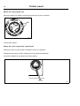
Mount the cover ring and the control knob
Mount the cover ring and rotate it clockwise until it is in position.
Rotate the inner knob until the locking device is pointing downwards.
Insert the screwdriver and press the locking device.
fig.7494
73
Control panel
59
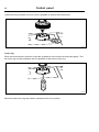
Mount the control knob on the inner knob. Continue to press with the screwdriver and turn the
control knob clockwise until it stops when it is in position.
fig.7495A
74
10.2 Control knob
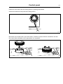
10.2.1 Replacement of control knob
Disconnect the power to the machine.
Insert a screwdriver in the upper hole.
fig.7491
75
Gently push the screwdriver inwards and turn the control knob counter-clockwise until the
screwdriver goes further in.
fig.7492
76
60
Control panel
Continue turning a quarter of a turn until it is possible to remove the control knob.
fig.7493
77
Cover ring
When the control knob is removed, insert the screwdriver in the lower hole and press gently. Turn
the cover ring counter-clockwise until it is possible to remove the cover ring.
fig.7490
78
Mount the new cover ring and rotate it clockwise until it is in position.
Control panel
61
Rotate the inner knob until the locking device is pointing downwards.
Insert the screwdriver and press the locking device.
fig.7494
79
Mount the new control knob on the inner knob. Continue to press with the screwdriver and turn
the control knob clockwise until it stops when it is in position.
fig.7495A
80
62
I/O modules
11 I/O modules
11.1 General
The machine can be equipped with either one or two I/O modules:
• I/O module type 81 is always installed in the machine at delivery. It controls internal machine
functions and outputs to heating, motors etc.
• I/O module type 2 is installed as an option. It controls the external functions and inputs from
payment and booking systems etc.
The functionality of I/O module inputs and outputs is depending on the parameter software
downloaded to the machine’s program device. The function options for the I/O modules are
indicated by a letter in the program designation for each module.
Machine fitted with two I/O modules
6G82 LG1 EL T5130 81O 2J
81O = Function options I/O module type 81 (internal functions).
2J = Function options I/O module type 2 (external functions).
Machine fitted with one I/O module
6G82 LG1 EL T5130 81O 2j
81O = Function options I/O module type 81 (internal functions).
2j = The letter that appears in lower case means that the machine is not fitted with I/O module type
2 but the downloaded parameter software is I/O module type 2 enabled.
I/O modules
63
Location
The parameter software installed in the machine’s program device on delivery is specified at the
front and back of the machine.
Using this article number, you can find the program designation and thereby identify I/O module
function options on the web.
T51 30
fig.W00281
81
64
I/O modules
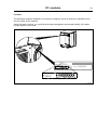
11.2 Replacement of I/O module
I/O module type 81 and I/O module type 2 are installed in the same way. If the machine has I/O
module type 2, it is located on I/O module type 81. The illustration shows replacement of I/O
module type 81.
Disconnect the power to the machine.
Demount the top panel.
fig.7600
82
I/O modules
65
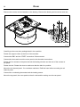
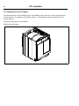
Remove the plastic cover and the electrical connections on the module. (Note the position of
the connections).
Remove the module by lifting it upwards.
fig.7601
83
Insert the new module and make sure it is in position.
Connect the electrical connections in the same way as before and mount the plastic cover.
If both I/O module type 81 and I/O module type 2 is to be replaced it is recommended to fit the
modules together before mounting in the machine.
1
2
3
fig.7602
84
Remount the upper rear panel.
Connect the power to the machine.
I/O modules
66
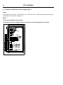
11.3 External connections to I/O module type 2
Inputs
The signal level may be 5 - 24V DC/AC or 100 - 240V AC. At 5 - 24V, the signal reference must be
connected to 3 and at 100 - 240V to 4.
Note!
Do not mix potentials on the inputs.
Connecting excessive voltage (> 24V) to connection 3 may damage the I/O modules.
1
2
3
4
5
6
7
8
9
10
11
12
13
14
15
16
17
18
19
fig.6236
85
I/O modules
67
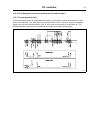
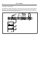
11.4 Circuit diagram of function options for I/O module type 2
11.4.1 Central payment (2J)
To start the machine from a central payment system, the payment system must transmit a start
pulse to the machine. The start pulse can be either 230V or 24V. In order to receive a feedback
signal once the machine has started, 230V or 24V must be connected to connection 19. The
feedback signal on connection 18 remains active (high) during the entire program.
fig.7440
86
68
I/O modules
11.4.2 Central payment (2J)
P rogra m run
The central payment or booking system shall transmit an active (high) signal to the machine once
permission has been granted to start the machine. The signal must remain active (high) during
drying. The signal can be either 230V or 24V. In order to receive a feedback signal once the
machine has started, 230V or 24V must be connected to connection 19. The feedback signal
remains active (high) during the entire program.
fig.7439
87
I/O modules
69
11.4.3 External coin meter/Central payment (2K)
The signal received from external coin meters must be a pulse.
fig.7438
88
70
I/O modules
11.4.4 Price reduction (2K)
By maintaining an activated (high) signal on connection 5 ("Price red"), the price of the program can
be reduced. This function has a number of uses, including providing reductions during a specific
period of the day. Whilst the signal remains active (high), the price of the program is reduced by the
percentage entered in the price programming menu.
fig.7441
89
Troubleshooting
71
12 Troubleshooting
12.1 General
The troubleshooting section is used to trace errors in the machine to a defective component or unit.
There is a memory in the CPU that will save the selected program for 10 minutes in the case
of power failure.
The machine will restart in pause mode if the power is turned on again within this time. For very
short power failure (less than 10 seconds) the machine will restart automatically.
Safety regulations
Troubleshooting may only be carried out by authorised personnel.
Take care during all work on the machine while the power is on.
Take care when measuring the motor control system since all components have a potential difference of
approximately 300V in relation to protective earth and neutral.The components will contain dangerous
voltages when the green LED on the motor control board is on. The motor control system will remain live for
30-60 seconds after cutting the power to the machine and the motor has stopped running.
Measurements
For information on measuring points, components and voltages, please refer to the electric
schematic supplied with the machine.
Troubleshooting
72
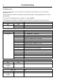
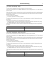
12.2 Error code
An error in the program or in the machine is indicated on the display by an error code and a
descriptive text.
The error codes are divided into different groups called “Major” comprising different error codes
called “Minor”.
The errors will be displayed as for example 12:15 NO VACUUM.
The following is a description of all Major groups followed by a description of each error code.
Error code
Text
Major
Minor
MAIN COMMON
11
REAL TIME CLOCK OUT OF ORDER
10
13
INITIALIZING FAILED
Error code
Text
Major
Minor
MAIN DRYER
1
O.H. THERMOSTAT - INLET AIR
12
2
O.H. THERMOSTAT - OUTLET AIR
3
INLET AIR SENSOR OPEN
4
INLET AIR SENSOR SHORT CIRCUITED
5
OUTLET AIR SENSOR OPEN
6
OUTLET AIR SENSOR SHORT CIRCUITED
8
CONDENSE WATER CONTAINER IS FULL
11
DRYING ERROR WITH RMC PROGRAM
12
DRYING ERROR WITH AUTOSTOP PROGRAM
13
DRYING ERROR WITH TIME PROGRAM
14
GAS ERROR PRESS GAS REST BUTTON
15
NO VACUUM
16
VACUUM SWITCH SHORTED
253
JUMPER 1
254
JUMPER 2
255
JUMPER 3
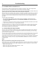
Error code
Text
Major
Minor
DRUM MOTOR
COMMON
1
O.H. DRUM MOTOR
20
Error code
Text
Major
Minor
FAN MOTOR
COMMON
1
30
O.H. FAN MOTOR
Troubleshooting
Error code
Text
Major
Minor
INTERNAL COM.
1
I/O BOARD MISHMASH
40
21
I/O COMMUNICATION
Error code
Text
Major
Minor
EXTERNAL COM.
PAYMENT
22
NO CBT COMMUNICATION
51
Error code
Text
Major
Minor
EXTERNAL COM.
CMIS
1
52
CMIS COMMUNICATION ERROR
73
74
Troubleshooting
12.3 Description of error codes and causes
MAIN COMMON
10:11 REAL TIME CLOCK OUT OF ORDER
The real time clock is used by the CPU, measuring time, power failure, error codes, etc.
The error code is activated if there is a time out in the communication with the internal real time
clock in the CPU or if the data sent to/from the real time clock is incorrect.
The error can only be removed by turning of the power to the machine for 30 seconds.
10:13 INITIALIZATION FAILED
The CPU has an internal time limit for initialization of the system.
The error code is activated if 15 seconds has expired during start up and the hardware still is not
initialized.
Press the control knob/start button to retry.
Troubleshooting
75
MAIN DRYER
12:1 O.H. THERMOSTAT - INLET AIR
The error code is activated if the protection thermostat for inlet air has trigged due to overheating.
The overheating thermostat for inlet air will be trigged at 195 °C.
The overheating thermostat for inlet air needs to be mechanically restored.
When the overheating thermostat for inlet air is restored it is possible to reset the error code from the
timer by a short press on the control knob/start button and the ongoing program will continue. A long
press on the control knob/start button will make the timer reset and ongoing program will be ended.
The error code can be trigged if:
• The inlet air sensor has stopped operating correctly.
• The fan has stopped operating.
• The airflow is obstructed, by lint, overload, etc.
If the overheating thermostat for inlet air is not trigged, but there still is an error code:
• Check the harness, connectors and functions by reading the electrical schematic and by using
the SHOW INPUTS menu when the machine is in service mode.
12:2 O.H. THERMOSTAT - OUTLET AIR
The error code is activated if the protection thermostat for outlet air has trigged due to overheating.
The overheating thermostat for outlet air will be trigged at 90°C.
The overheating thermostat for outlet air needs to be mechanically restored.
When the overheating thermostat for outlet air is restored it is possible to reset the error code from
the timer by a short press on the control knob/start button and the ongoing program will continue.
A long press on the control knob/start button will make the timer reset and ongoing program will
be ended.
The error code can be trigged if:
• The outlet air sensor has stopped operating correctly.
If the overheating thermostat for outlet air is not trigged, but there is still an error code:
• Check the harness, connectors and functions by reading the electrical schematic and by using
the SHOW INPUTS menu when the machine is in service mode.
76
Troubleshooting
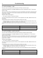
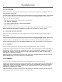
12:3 INLET AIR SENSOR - OPEN
The error code is activated if the inlet air sensor (PT100) or its wires is open.
If the inlet air temperature in the SHOW INPUTS menu show a temperature of 222 °C the inlet air
sensor is open.
When the inlet air sensor is restored the error code is automatically reset and the ongoing program
will continue. A long press on the control knob/start button will make the timer reset and ongoing
program will be ended.
The error code can be trigged if:
• The sensor, harness or connector is broken.
The sensor shall measure around 110 Ohm in room temperature, see table. (Measure direct over
the sensor).
If the measure of inlet air sensor is OK, but there is still an error code:
• Check the harness, connectors and functions by reading the electrical schematic and by using
the SHOW INPUTS menu when the machine is in service mode.
If the input for the inlet air sensor is short circuited, the timer will display the inlet air temperature of
0 °C.
Inlet air sensor resistor value
Temperature
100 Ohm
0 °C
107–112 Ohm
20–30 °C
176 Ohm
200 °C
12:4 INLET AIR SENSOR - SHORT-CIRCUITED
The error code is activated if the inlet air sensor (PT100) or its wires is short circuited.
If the inlet air temperature in the SHOW INPUTS menu show a temperature of 0 °C the inlet air
sensor is short circuited.
When the inlet air sensor is restored the error code is automatically reset and the ongoing program
will continue. A long press on the control knob/start button will make the timer reset and ongoing
program will be ended.
The error can be trigged if:
• The sensor, harness or connector is broken.
The sensor shall measure around 110 Ohm in room temperature, see table. (Measure direct over
the sensor).
If the measure of inlet air sensor is OK, but there is still an error code:
• Check the harness, connectors and functions by reading the electrical schematic and by using
the SHOW INPUTS menu when the machine is in service mode.
If the input for the inlet air sensor is short circuited, the timer will display the inlet air temperature
of 222 °C.
Inlet air sensor resistor value
Temperature
100 Ohm
0 °C
107–112 Ohm
20–30 °C
176 Ohm
200 °C
Troubleshooting
77
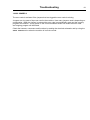
12:5 OUTLET AIR SENSOR - OPEN
The error code is activated if the outlet air sensor or its wires is open.
If the outlet air temperature in the SHOW INPUTS menu show a temperature of -10 °C the outlet air
sensor is open.
When the outlet air sensor is restored the error code is automatically reset and the ongoing program
will continue. A long press on the control knob/start button will make the timer reset and ongoing
program will be ended.
The error code can be trigged if:
• The sensor, harness or connector is broken.
The sensor shall measure around 5 K Ohm in room temperature, see table. (Measure direct over
the sensor).
If the measure of outlet air is OK, but there is still an error code:
• Check the harness, connectors and functions by reading the electrical schematic and by using
the SHOW INPUTS menu when the machine is in service mode.
If the input for the outlet air sensor is short circuited the timer will display the inlet air temperature
of 100 °C.
Outlet air sensor resistor value
Temperature
26.7 K Ohm
– 10 °C
6–3.9 K Ohm
20–30 °C
330 Ohm
100 °C
12:6 OUTLET AIR SENSOR - SHORT-CIRCUITED
The error code is activated if the outlet air sensor or its wires is short circuited.
If the outlet air temperature in the SHOW INPUTS menu show a temperature of 100 °C the outlet air
sensor is open.
When the outlet air sensor is restored the error code is automatically reset and the ongoing program
will continue. A long press on the control knob/start button will make the timer reset and ongoing
program will be ended.
The error code can be trigged if:
• The sensor, harness or connector is broken.
The sensor shall measure around 5 K Ohm in room temperature, see table. (Measure direct over
the sensor).
If the measure of outlet air sensor is OK, but there is still an error code:
• Check the harness, connectors and functions by reading the electrical schematic and by using
the SHOW INPUTS menu when the machine is in service mode.
If the input for the outlet air sensor is open circuited the timer will display the inlet air temperature of
0 °C.
Outlet air sensor resistor value
Temperature
26.7 K Ohm
– 10 °C
6–3.9 K Ohm
20–30 °C
330 Ohm
100 °C
78
Troubleshooting
12:8 CONDENSE WATER CONTAINER IS FULL
The pump will run when a program starts for normally 15 seconds. Then it will run again after
normally 3 minutes. The pump will also run if the input for the float is trigged.
The error code is activated if the pump has tried to empty the condense water container without the
signal from the float in the condense water container has been deactivated.
When the float in the condense water container is restored it is possible to reset the error code from
the timer. The error code is reset from the timer by a short press on the control knob/start button.
A long press on the control knob/start button will make the timer reset and ongoing program will
be ended.
The error code can be trigged if:
• The condense water container is full and the pump is not operating. Check the pump by
activating the CONDENSER PUMP menu in the ACTIVATE OUTPUTS menu when the machine
is in service mode.
• If the pump is running and no water is coming out, the drain is blocked or the float is out of order.
• If water coming out of the hose, it might be partly blocked.
If the pump does not run or if there is no level in the condense water container check the harness,
connectors and functions by reading the electrical schematic and by using the SHOW INPUTS
menu when the machine is in service mode.
12:11 DRYING ERROR WITH RMC PROGRAM
The error code is activated if the RMC system does not register that the clothes are dry within the
maximum drying time. When the error is trigged the machine will automatically go to the cooling
module before the program ends.
The error code is reset from the timer by a short press on the control knob/start button. A long press
on the control knob/start button will make the timer reset and ongoing program will be ended.
If the clothes are still wet after maximum drying time and the dryer is not overloaded, check that the
heating system is working correct by using the ACTIVATE OUTPUTS menu when the machine is
in service mode.
Note!
Make sure that the fan is active before turning on the heat.
If the clothes are dry, check the RMC system and harness, connectors and functions by reading the
electrical schematic and by using the SHOW INPUTS menu when the machine is in service mode.
• RMC value no load = 0%
• RMC value 100K Ohm between lifter and drum = ~24%
• RMC value system short circuit = 50%
Troubleshooting
79
12:12 DRYING ERROR WITH AUTOSTOP PROGRAM
The error code is activated if the Auto Stop system does not register that the clothes are dry within
the maximum drying time. When the error is trigged the machine will automatically go to the cooling
module before the program ends.
The error code is reset from the timer by a short press on the control knob/start button. A long press
on the control knob/start button will make the timer reset and ongoing program will be ended.
If the clothes are still wet after maximum drying time and the dryer is not overloaded, check that the
heating system is working correct by using the ACTIVATE OUTPUTS menu when the machine is
in service mode.
Note!
Make sure that the fan is active before turning on the heat.
If the clothes are dry, check the outlet air sensor and harness, connectors and functions by reading
the electrical schematic and by using the SHOW INPUTS menu when the machine is in service mode.
12:13 DRYING ERROR WITH TIME PROGRAM
The error code is activated if a time program has continued longer than the maximum drying time
without the door has been opened.
When the error is trigged the machine will automatically go to the cooling module before the
program ends.
The error code is reset from the timer by a short press on the control knob/start button. A long press
on the control knob/start button will make the timer reset and ongoing program will be ended.
12:14 GAS ERROR PRESS GAS RESET BUTTON
The error code is activated if no flame has been detected by the gas control box. The gas control
box trig an input on the timer system, which generates the error code.
The metal probe of the flame sensor generates an electrical current when exposed to the burner's
flame. This signal is detected by the ignition control module which, in turn, cuts off the gas valve
immediately if the sensor does not indicate flame within 10 seconds. The gas control box does
3 attempts to ignite. The integrity of the sensor's electrical connection is, therefore, critical to
proper operation of this system. When the gas control box is in error mode a red LED is active on
the gas control box.
The timer sends a reset signal to the gas control box by a short press of the start button or service
button (depending on market and segment). When the gas control box receive a reset command
it removes the error. The timer will automatically restart the program when the error is removed
from the gas control box and when heat is allowed (vacuum needed) the gas control box will try
to ignite the gas again. A long press on the control knob/start button will make the timer reset
and ongoing program will be ended.
The gas error can also be reset at the gas control box. The machine will automatically restart
when the error is restored.
The error code can be trigged if:
•
The gas control box fails to ignite. Check the gas supply and nozzle pressure.
If the gas control box do not have a gas error but the timer does, check the harness, connectors
and functions by reading the electrical schematic and by using the SHOW INPUTS menu when the
machine is in service mode.
80
Troubleshooting
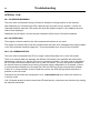
12:15 NO VACUUM
The error code is activated if the vacuum/pressure switch (normally open) is not trigged within set
time, normally 15 seconds.
The error code is reset from the timer by a short press on the control knob/start button. A long press
on the control knob/start button will make the timer reset and ongoing program will be ended.
The error code can be trigged if:
• The fan is not operating or blows in the wrong direction.
• The airflow is obstructed.
• The vacuum switch sensor or hose is disconnected.
• The lint drawer is open, etc.
Check the harness, connectors and functions by reading the electrical schematic and by using the
SHOW INPUTS and ACTIVATE OUTPUTS menus when the machine is in service mode.
12:16 VACUUM SWITCH SHORTED
The error code is activated if the vacuum/pressure switch was already closed when a program
was started.
The error code is reset from the timer by a short press on the control knob/start button. A long press
on the control knob/start button will make the timer reset and ongoing program will be ended.
Check the vacuum switch/pressure sensor, harness, connectors and functions by reading the
electrical schematic and by using the SHOW INPUTS menu when the machine is in service mode.
12:253 JUMPER 1
The error code is activated if the jumpers that has trigged the error code is missing.
Jumpers are a by-pass of input not used in the machine. How many jumpers used is depending on
configuration. When the jumper is restored the error code is automatically reset and the ongoing
program will continue. A long press on the control knob/start button will make the timer reset
and ongoing program will be ended.
Check the harness, connectors and functions by reading the electrical schematic and by using the
SHOW INPUTS menu when the machine is in service mode.
12:254 JUMPER 2
The error code is activated if the jumpers that has trigged the error code is missing.
Jumpers are a by-pass of input not used in the machine. How many jumpers used is depending on
configuration. When the jumper is restored the error code is automatically reset and the ongoing
program will continue. A long press on the control knob/start button will make the timer reset
and ongoing program will be ended.
Check the harness, connectors and functions by reading the electrical schematic and by using the
SHOW INPUTS menu when the machine is in service mode.
Troubleshooting
81
12:255 JUMPER 3
The error code is activated if the jumpers that has trigged the error code is missing.
Jumpers are a by-pass of input not used in the machine. How many jumpers used is depending on
configuration. When the jumper is restored the error code is automatically reset and the ongoing
program will continue. A long press on the control knob/start button will make the timer reset
and ongoing program will be ended.
Check the harness, connectors and functions by reading the electrical schematic and by using the
SHOW INPUTS menu when the machine is in service mode.
82
Troubleshooting
DRUM MOTOR COMMON
20:1 O.H. DRUM MOTOR
Not valid for washer extractors with MCU.
This error code is activated if the overheating protection for the drum motor has trigged.
The overheating protection is automatically restored. When the overheating protection is restored
the error code is automatically reset and the ongoing program will continue. A long press on the
control knob/start button will make the CPU reset and ongoing program will be ended.
The error code can be trigged if:
• The motor is very warm. Check that the vent holes in the motor are not covered.
If the overheating protection is not trigged, but there is still an error code:
• Check the harness, connectors and functions by reading the electrical schematic and by using
the SHOW INPUTS menu when the machine is in service mode.
20:2 NO MOTOR COMMUNICATION
This error code arises if the first message sent from the CPU to the MCU was not replied to
during start up.
Action
• Check that there is power reaching the MCU. Check the fuses in the Protection Cable. If one of
the components in the Protection Cable is damaged, the cable must be replaced.
• Check that the indicator LED on the MCU is on. The LED can be seen by looking down by
the MCU edge connections.
• Check that the communication cable between the CPU board and the MCU is intact and not
damaged. Measure also with a reference instrument to see whether there is contact between all
the leads in the communication cable.
20:3 LOST MOTOR COMMUNICATION
This error code arises if the communication between the CPU and the MCU has stopped working.
Action
• Check that there is power reaching the MCU. Check the fuses in the Protection Cable. If one of
the components in the Protection Cable is damaged, the cable must be replaced.
• Check that the indicator LED on the MCU is on. The LED can be seen by looking down by
the MCU edge connections.
• Check that the communication cable between the CPU board and the MCU is intact and not
damaged. Measure also with a reference instrument to see whether there is contact between all
the leads in the communication cable.
Troubleshooting
83
FAN MOTOR COMMON
30:1 O.H. FAN MOTOR
The error code is activated if the overheating protection for blower motor has trigged.
The overheating protection is automatically restored. When the overheating protection is restored
the error code is automatically reset and the ongoing program will continue. A long press on the
control knob/start button will make the timer reset and the ongoing program will be ended.
The error code can be trigged if:
• The motor is very warm. Check that the vent holes in the motor are not covered.
If the overheating protection is not trigged, but there is still an error code:
• Check the harness, connectors and functions by reading the electrical schematic and by using
the SHOW INPUTS menu when the machine is in service mode.
84
Troubleshooting
INTERNAL COM.
40:1 I/O BOARD MISHMASH
The error code is activated if wrong I/O board is adressed to wrong position in the machine.
After addressing of I/O boards the CPU reads the type of board in every position. If there is a
mishmash between what the CPU reads and what the software expect on any address the error
code will be displayed.
Readdress all I/O boards. Use the electric schematic to find correct I/O board to address.
40:2 I/O INTERLOCK
The program unit has read from the I/O board that the interlock is not active.
The reason for interlock failure can be a problem with the hatch lock, damaged motor supply cables
or the I/O board with interlock voltage etc. The most probable error source is the I/O board.
40:21 I/O COMMUNICATION
The error code is activated if the CPU no longer communicate with one or more I/O boards.
There is an internal data bus between the different I/O boards in the machine with information
about inputs, outputs, etc. that the CPU use to control the machine. The error code is activated if
the CPU has lost communication with one or more I/O boards. The error will also be activated if
the service button is pressed on the wrong I/O board during configuration of I/O boards. If there
is communication between the I/O board and CPU the LED next to the service button will flash.
If there is no communication to the I/O board but power, the LED will light when the button is
pressed on the I/O board.
Check that all I/O boards are configured in I/O CONFIGURATION menu when the machine is
in service mode.
If all I/O boards present in the list check the LED and harness, connectors and functions by reading
the electrical schematic.
Troubleshooting
85
EXTERNAL COM. PAYMENT
51:22 NO CBT COMMUNICATION
Machine with payment system using serial communication to machine. Serial communication with
payment system interrupted.
Check network cable between machine and payment system.
Check that payment system is operational.
To reset machine to working state without repairing payment system, use Reset CBT communication
in service mode. (Requires password).
86
Troubleshooting
EXTERNAL COM. CMIS
52:1 CMIS COMMUNICATION ERROR
Communication between machine and network computer has been interrupted.
Check network cable between machine and network.
Check that CMIS on network computer is operational.
The machine can be operated but statistics could be affected and data could be lost.
Maintenance
87
13 Maintenance
13.1 Clean the fan, the exhaust duct and the fresh-air intake to the room
Check that the following are not clogged by lint and dust or otherwise blocked and clean with a
vacuum cleaner:
• The fan. Be careful not to damage the fan.
• Exhaust duct.
• Fresh-air intake to the room.
Check that the exhaust system connections are tight.
13.2 Clean the glide surface for the RMC graphite collectors
Clean the glide surface for the RMC graphite collectors on the outside of the drum (A).
A
fig.7462
90
88
Maintenance
13.3 Clean the area around the drum
Disconnect the power to the machine.
Demount the top panel.
Remove all lint around the drum and in the area over the drum with a vacuum cleaner.
fig.7603
91
Maintenance
89
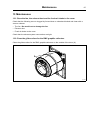
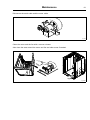
13.4 Clean the motor
Disconnect the power to the machine.
Demount the casing over the rear panel and the cover panel at the air outlet.
Demount the top panel.
Disconnect the overheating thermostat and the heating sensor and push the connections into the
hole.
T5130
T5130C
fig.7519A
92
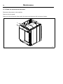
Demount the air channel panel. On condense machines: Pull out the hose to the drain from its
upper connection.
Loosen the belt around the drum.
T5130
T5130C
fig.7522A
93
90
Maintenance
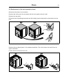
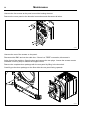
Unscrew the four screws at the panel around the heating element.
Demount the cover panel to the electrical connections and disconnect all wires.
fig.7527
94
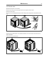
Unscrew the rest of the screws on the panel.
Disconnect the RMC and cut the cable ties. If there is a “FREE” connection, disconnect it.
At the front of the machine: Open the door and remove the two plugs. Loosen the screws counter
clockwise until they stop to release the support rollers.
Remove the complete drum package with the rear panel by lifting in the drum belt.
Carefully put the drum package on the floor witht the rear panel facing upwards.
fig.7531
95
Maintenance
91
Disconnect the earth cable and the motor cable.
fig.7539
96
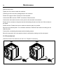
Clean the motor and the fan with a vacuum cleaner.
Also clean the area around the motor and fan and other areas if needed.
fig.7540B
97
Maintenance
92
Remount the motor.
Tighten the four screws under the machine.
Carefully put the new drum package back in the machine.
Fasten the support rollers at the front of the machine.
Connect the RMC and the “FREE” connection if disconnected.
Connect the wires and mount the cover panel to the electrical connections.
Fasten the four screws at the panel around the heating element and the rest of the screws on
the panel.
Fasten the belt. Rotate the drum to make sure that the belt is in position.
Mount the air channel panel. On condense machines: Refit the hose before mounting the air
channel panel.
Connect the overheating thermostat and the heating sensor.
Mount the top panel, the cover panel at the air outlet and the casing over the rear panel.
13.5 Check the belt
Check that both of the belts are not worn out. Replace if necessary.
T5130
T5130C
fig.7522A
98
lastpage
Electrolux Laundry Systems Sweden AB
341 80 Ljungby, Sweden
www.electrolux.com/laundrysystems
Share more of our thinking at www.electrolux.com