1
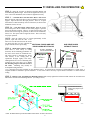
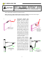
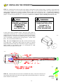
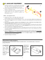
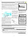
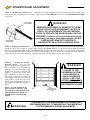
INSTALLER: Place this manual in the plastic envelope provided and permanently
attach to the wall near the pushbutton.
INSTALLATION AND
OWNER’S MANUAL
6000 SERIES
Residential Vehicular Garage Door Operator
MODELS: 6000, 6500, 6500-P & J6500
107063
READ THIS MANUAL
Serial #:
Date Installed:
As of date of manufacture,
meets all ANSI/UL 325
Safety Requirements for
Vehicular Garage Door
Operators
CAREFULLY BEFORE
Your Dealer:
INSTALLATION OR USE
1
TABLE OF CONTENTS
Product Features ................................................................................... 2
Component Identification/Tools Required ........................................... 4
Section A: Assembly Instructions ....................................................... 5
Section B: Installation Notes................................................................ 6
Section C: Installing the Operator ....................................................... 7
Identify Your Door Type ............................................................. 7
Mounting the Front Bracket ....................................................... 8
Mounting the Power Head.......................................................... 9
Door Arm Installation ............................................................... 10
Pushbutton Connection ........................................................... 11
Section D: Auxiliary Equipment ......................................................... 13
Installation of All-Clear ............................................................ 13
Installation of Radio Controls.................................................. 14
Installation of the Super Station .............................................. 15
Operating Parameters.......................................................................... 16
Section F: Operation and Adjustment Instructions .......................... 17
Safety Notes ............................................................................. 17
Testing the Sensitivity ............................................................. 18
Testing the Reversing System ................................................ 18
Testing the All-Clear................................................................. 19
Operating the Super Station .................................................... 19
Operator Wiring Diagram .................................................................... 20
Auxiliary Equipment Wiring Diagram ................................................. 21
Installation Checklist ........................................................................... 22
Troubleshooting Guide........................................................................ 23
READ THESE STATEMENTS CAREFULLY AND FOLLOW THE
INSTRUCTIONS CLOSELY.
The Warning and Caution boxes throughout this manual are there to protect you and
your equipment. Pay close attention to these boxes as you follow the manual.
WARNING
CAUTION
WARNING
CAUTION
Indicates a MECHANICAL
hazard of INJURY OR
DEATH. Gives instructions
to avoid the hazard.
Indicates a MECHANICAL hazard
of DAMAGE to your gate, gate
operator, or equipment. Gives
instructions to avoid the hazard.
Indicates an ELECTRICAL
hazard of INJURY OR
DEATH. Gives instructions
to avoid the hazard.
Indicates an ELECTRICAL hazard
of DAMAGE to your gate, gate
operator, or equipment. Gives
instructions to avoid the hazard.
2
PRODUCT FEATURES
The purpose of this booklet is to provide assembly,
installation and operation information concerning the 6000
Series Residential Garage Door Openers and related Accessory
Products.
NOTICE
IT IS IMPORTANT THAT THIS INSTRUCTION
MANUAL BE READ AND UNDERSTOOD
COMPLETELY BEFORE INSTALLATION OR
OPERATION IS ATTEMPTED.
NOTICE
THE IMPORTANT SAFEGUARDS AND
INSTRUCTIONS IN THIS MANUAL CANNOT
COVER ALL POSSIBLE CONDITIONS AND
SITUATIONS WHICH MAY OCCUR DURING ITS
USE. IT MUST BE UNDERSTOOD THAT
COMMON SENSE AND CAUTION MUST BE
EXERCISED BY THE PERSON(S) INSTALLING,
MAINTAINING AND OPERATING THE
EQUIPMENT DESCRIBED HEREIN. DO NOT
USE THIS EQUIPMENT FOR ANY OTHER THAN
ITS INTENDED PURPOSE - OPERATING
OVERHEAD GARAGE DOORS.
STANDARD FEATURES:
Entrapment Protection Devices: The 6000 Series
All-Clear™ Photosystem (light beam across the door
opening) can be easily connected to the Opener. Control
circuitry monitors the device continuously for proper
operation. (Page 20) Consult the factory for
compatibility of other auxiliary entrapment protection
devices.
Constant Contact To Close: For utmost safety, the
standard operation mode requires constant contact on the
mechanical Push Button to close the door if an Auxiliary
Entrapment Protection Device (see above) IS NOT
installed or if the Device fails. In this mode of
operation, a Radio Transmitter cannot be used to close
the door. (Page 13 & 14)
Momentary Contact To Close: After installing an
All-Clear™ Photosystem Auxiliary Entrapment
Protection Device the close operation mode is
automatically converted to momentary contact of the
mechanical Push Button, and a portable Radio
Transmitter can be used to close the door. (PageZ16)
All-Clear™ Photosystem: An invisible infrared
beam of light guards the door opening and reverses a
downward moving door if the beam is broken by a
stationary or moving object. The 6000 Series motor
control circuitry constantly monitors the All-Clear
Photosystem for proper operation.
Sensing System: A built-in sensing system detects
obstructions during door operation. If in the downward (close)
travel mode, the Opener will sense an obstruction and reverse
the direction of the door. In the open mode, the Opener will
stop. Since all doors are different, the Sensing System has
independent adjustments for customizing the level of force
required for the normal opening and closing of specified doors.
( Page 18)
Close Limit Switch: In winter months it's common for
small pieces of ice or packed snow to be trapped under the
door. Ground swelling can also effect the close limit setting of
the Opener. The 6000 Series Close Limit Switch overrides the
Sensing System during the last one inch of closing travel and
prevents the door from reversing if it encounters an obstruction
at this point.
Alternating Action Operation:
The mechanical wall
pushbutton functions in an Open/Stop/Close/Stop & Reverse
mode in normal operation. (Page 16)
Emergency Release: A pull cord allows separation of the
drive mechanism and manual operation of the door when
desired, as in the event of a power failure. (Page 11)
Automatic Reconnection:
Once power is restored, or
automatic operation of the door is again desired, initiating
operation in the normal manner (Push Button, Radio Control,
etc.) will effect automatic reconnection of the Emergency
Release Mechanism. (Page 11)
Connections For Continuously Monitored Auxiliary
3
OPTIONAL FEATURES:
Digital Radio Controls: The 6000 Series Openers
covered in this Manual can be fitted with optional Radio
Controls. Up to 19,683 private codes can be easily
selected without use of tools. (PageZ15)
Super Station (Deluxe Wall Push Button): A
feature-packed accessory unit, the Super Station allows
access to all of the Opener's functions. Independent
Open, Close, and Stop buttons permits full control of the
door’s operation. The Opener's built-in light can be
turned on or off independent of door operation. A
Security Switch allows the Opener to be deactivated for
extended periods of time. A Security Disable switch is
provided if the garage door is the only entryway into the
garage. Lighted Push Buttons enhance nighttime use.
(Page 16)
Keyless Entry System: A tamper resistant outdoor
keypad, the optional Keyless Entry System permits entry
to the garage without use of key or radio transmitter.
Easily programmable, it accommodates four separate
access codes of 4 digits. Lighted Buttons enhance
nighttime use.
COMPONENT IDENTIFICATION
DRIVE
CHAIN
TROLLEY
OUTER HALF
MASTER
LINKS
OPENER HEAD UNIT
ONE-PIECE
DOORS
DOOR ARMS
CHAIN
GUARD
SECTIONAL
DOORS
WALL
MOUNTING
BRACKET
DOOR MOUNTING
BRACKETS
TEE RAIL
RUBBER BUMPER
!
W AR N I N G
FRONT IDLER
Child can be pinned under automatic garage
door. Death or serious injury can result.
• Never let child walk or run under moving door.
• Never let child use door opener controls.
• Always keep moving door in sight.
• If person is pinned, push control button or use
emergency release.
• Test door opener monthly:
RELEASE ROPE
AND HANDLE
ALL-CLEAR
PHOTOSYSTEM
Refer to your owner’s manual
Place one-inch object (or 2x4 laid flat) on floor.
If door fails to reverse on contact, adjust opener.
If opener still fails to reverse door, repair or replace opener.
PUSHBUTTON
“WARNING” LABEL
OPENER
HARDWARE
BAG
CHAIN LIMIT
CAM
ALL-CLEAR HARDWARE
WALL PUSHBUTTON
TOOLS REQUIRED
HAMMER
DRILL
1/2” OPEN END
WRENCH
HACKSAW
DRILL & BITS
STEPLADDER SOCKET WRENCH
3/8” SOCKET
7/16” SOCKET
SMALL SCREW DRIVER
(1/8” HEAD)
LEVEL
WOOD
BLOCK
SCREW DRIVER
TAPE MEASURE
4
A: ASSEMBLY INSTRUCTIONS
If Your Opener Is Supplied Fully Assembled, Please Disregard This Page.
NOTE: The Tee Rail/Chain Assembly is packaged separately from the Power Unit.
104363
The Inner Trolley half, Front Idler Sprocket, Chain, Restraining Device and Limit Cams
are assembled on the Tee Rail at the factory. Follow the steps outlined below to
complete assembly prior to installation. Refer to the component identification
illustrations on the previous page.
STEP 1: Protect the Power Unit cover from scratching during assembly by placing it on
cardboard. Remove the two 5/16"-18 washered nuts and save them for later use.
STEP 2: Position the Tee Rail/Chain Assembly box near the Power Unit. Open the box
and locate the Installation Hardware Packet.
STEP 3: Locate the Outer Trolley half (packaged with the Power Unit) and slide it onto
the Tee Rail/Chain Assembly with the arrow on the Trolley pointing toward the Door
(Front Idler).
STEP 4: Using a 1/2" wrench, loosen the outer nut on the Chain
104364
Tension Bracket until it is at the end of the threaded rod. Remove
and discard the small "S" hook used to keep the chain tight
during shipping.
STEP 5: Loop the chain around the Idler and Drive Sprocket on
top of the Power Unit and then position the Tee Rail on the studs. CHAIN
Secure with the two nuts removed in Step 1.
MASTER
LINK
OUTER
NUT
INNER
NUT
MASTER
LINK
CHAIN
Slightly tension the Chain by tightening the outer nut on the Chain
Tension Bracket. Remove and discard the tape at each end of the Tee Rail Assembly. After double-checking the Chain's alignment
with the Drive Sprocket and Front Idler Wheel, use the inner and outer adjusting nuts on the Chain Tension Bracket to adjust the chain
to the proper tension, making sure the chain does not twist. When correctly adjusted, the Chain should show no droop and be
approximately 1/2" above the base of the Tee Rail.
NOTE: If the chain is too loose or too tight, improper operation and/or excessive sprocket noise may result.
STEP 6: Position the open and
close Limit Switch Actuators to
accept the Limit Cams on the chain,
as shown. Install the Chain Guard
by sliding the key-shaped hole onto
the groove on the Idler Sprocket
Shaft and fully seating the rear hole
over the Drive Sprocket Shaft. The
Limit Cams are installed at the
factory. Their settings should be
considered temporary and may be
changed as required during installation.
104365
STEP 7: Install the Rubber Bumper into its mounting hole on the Tee Rail (see illustration above for location). Secure the Bumper
to the bottom of the Tee Rail using one 5/16"-18 X 1" hex head bolt and one 5/16"-18 washered nut (supplied) Tighten the bolt a
MAXIMUM of 1.5 turns after the bolt and nut are snug.
STEP 8: Recheck the nuts used to secure the Tee Rail to the
CHAIN
GUARD
Power Unit, making sure they are tight. Recheck the Chain
tension, Chain twist, Chain Guard and the position of both the
Close Limit Switch and Open Limit Switch Actuators.
Assembly is now complete and you are ready to
begin installation of the opener.
CLOSE LIMIT
SWITCH
ACTUATOR
104366
DOWN
LIMIT CAM
DRIVE
SPROCKET
IDLER
SPROCKET
5
B: IMPORTANT INSTALLATION
WARNING!
TO REDUCE THE RISK OF SEVERE INJURY
OR DEATH: READ AND FOLLOW ALL
INSTALLATION INSTRUCTIONS!
• REINFORCE LIGHTWEIGHT FIBERGLASS,
ALUMINUM AND STEEL DOOR TOP SECTIONS
TO AVOID DAMAGE AND TO INSURE PROPER
OPERATION OF THE SAFETY REVERSE
SYSTEM.
CONTACT YOUR DOOR
MANUFACTURER FOR A REINFORCEMENT
KIT.
WARNING: AN UNBALANCED DOOR OR
ONE THAT STICKS OR BINDS MAY
PREVENT THE SENSING SYSTEM FROM
WORKING PROPERLY, CAUSING INJURY OR
DEATH.
ENSURE DOOR IS PROPERLY
BALANCED AND ELIMINATE ANY STICKING OR
BINDING PRIOR TO INSTALLATION OF
OPERATOR.
• DO NOT CONNECT THE OPENER TO A
POWER SOURCE UNTIL INSTRUCTED TO DO
SO.
• A properly balanced door will open slowly from a
3/4 open position, close slowly from a 3/4 closed
position, and remain still at a 1/2 open position. If
the door is not properly balanced, HAVE A
QUALIFIED SERVICE PERSON MAKE REPAIRS
TO CABLES, SPRING ASSEMBLIES AND
OTHER DOOR HARDW ARE BEFORE
INSTALLING THE OPENER
• CHECK LOCAL BUILDING AND ELECTRICAL
CODES FOR MANDATORY INSTALLATION
AND WIRING REQUIREMENTS.
• CONNECT POWER CORD ONLY TO A
PROPERLY GROUNDED OUTLET.
IF
PERMANENT WIRING IS REQUIRED BY
CODES, DISCONNECT POWER AT FUSE BOX
OR CIRCUIT BREAKER BEFORE ATTEMPTING
ANY WIRING CONNECTIONS.
WARNING: YOUR GARAGE DOOR IS THE
LARGEST MOVING OBJECT IN YOUR
HOUSE, THE SPRINGS, PULLEYS, CABLES
AND MOUNTING HARDWARE UTILIZED TO
BALANCE ITS OPERATION ARE UNDER
EXTREME TENSION AT ALL TIMES AND CAN
CAUSE SERIOUS PERSONAL INJURY, EVEN
DEATH, IF DISTURBED. DO NOT ATTEMPT
ADJUSTMENT.
• LOCATE THE CONTROL PUSH BUTTON:
A. WITHIN SIGHT OF THE DOOR, AND,
B. AT A MINIMUM HEIGHT OF 5 FT SO SMALL
CHILDREN CAN'T REACH IT, AND,
C. AWAY FROM MOVING PARTS OF THE
DOOR.
• CALL A QUALIFIED SERVICE PERSON TO
MOVE, LOOSEN OR ADJUST DOOR SPRINGS
OR HARDWARE.
•
• INSTALL THE ENTRAPMENT WARNING LABEL
NEXT TO THE CONTROL PUSH BUTTON IN A
PROMINENT LOCATION.
INSTALL THE
EMERGENCY RELEASE INSTRUCTION CARD,
ATTACHING IT ON OR NEXT TO THE
EMERGENCY RELEASE.
REMOVE ALL ROPES AND REMOVE OR
MAKE INOPERATIVE ALL LOCKS CONNECTED
TO THE GARAGE DOOR BEFORE INSTALLING
THE OPENER.
• ADJUST THE SENSITIVITY ADJUSTMENTS
ENOUGH TO ALLOW THE DOOR TO
OPERATE, BUT NOT SO FIRMLY AS TO EXERT
EXCESSIVE
PRESSURE
ON
AN
OBSTRUCTION BEFORE REVERSING.
• DO NOT WEAR RINGS, WATCHES OR LOOSE
CLOT HING
W HILE
IN ST ALL ING
OR
SERVICING
GARAGE DOOR OPENERS.
WEAR SAFETY GOGGLES OR OTHER
PROTECTIVE EYEWEAR.
• AFTER INSTALLING THE OPENER, THE DOOR
SHOULD REVERSE WHEN IT CONTACTS A
1-1/2" HIGH OBJECT (A PIECE OF STANDARD
2 X 4 BOARD LAID FLAT) ON THE FLOOR.
• IF POSSIBLE, INSTALL THE DOOR OPENER
7zFT OR MORE ABOVE THE FLOOR. MOUNT
THE EMERGENCY RELEASE 6 FT ABOVE THE
FLOOR.
6
C: INSTALLING THE OPERATOR
IMPORTANT!
IDENTIFY YOUR DOOR TYPE FROM THOSE ILLUSTRATED BELOW AND FOLLOW
INSTRUCTIONS FOR THAT TYPE OF DOOR
104367
104368
SECTIONAL DOOR
CURVED TRACK
HIGH ARC OF
DOOR TRAVEL
ONE PIECE DOOR
HORIZONTAL TRACK
JAMB HARDWARE
ONE PIECE DOOR
NO TRACK
JAMB HARDWARE
HIGH ARC OF
DOOR TRAVEL
HIGH ARC OF
DOOR TRAVEL
TRACK
DOOR
TRACK
DOOR
ONE PIECE DOOR
NO TRACK
PIVOT HARDWARE
HIGH ARC OF
DOOR TRAVEL
DOOR
DOOR
JAMB
HARDWARE
FOR THESE TYPES OF DOORS USE 1/3 HP
MODEL 6000 OR 1/2 HP MODEL 6500 OR 6500-P.
USE 7 FT, 8 FT OR 10 FT RAIL
(MATCH DOOR HEIGHT)
WARNING
HORIZONTAL
LINE
PIVOT
FOR THESE TYPES OF DOORS USE
1/2 HP MODEL J6500.
USE 7J RAIL
(FOR DOOR HEIGHT UP TO 8 FT)
SPRINGS, PULLEYS, CABLES AND MOUNTING HARDWARE USED TO
BALANCE YOUR GARAGE DOOR ARE UNDER EXTREME TENSION AT ALL
TIMES AND CAN CAUSE SEVERE INJURY OR DEATH IF DISTURBED.
DO NOT ATTEMPT ADJUSTMENT.
VERTICAL
CENTERLINE
STEP 1: Mounting the Front Bracket — Sectional Doors and OnePiece Doors with Track (For One-Piece Doors without track see Step 1A,
next): Mark a vertical centerline on the header above the door. By
manually raising the door, determine the high arc of the door’s travel (see
illustration, above left) and using a level, transfer this measurement to the
header (see illustration at left). Draw a horizontal line, crossing the
previously drawn centerline, at this point. Install the Front Mounting
Bracket securely wit lag screws as shown on the following page. If
necessary, reinforce the header with steel angle iron or wood to ensure a
secure mount.
104369
WARNING
FRONT MOUNTING BRACKET MUST BE INSTALLED TO A STRUCTURAL SUPPORT
(STUD) ON THE HEADER WALL. FAILURE TO DO SO COULD CAUSE SENSING
SYSTEM TO MALFUNCTION, RESULTING IN ENTRAPMENT, INJURY OR DEATH.
REINFORCE HEADER IF NECESSARY USING A 2 x 6 AND LAG SCREWS
(NOT PROVIDED).
7
C: INSTALLING THE OPERATOR
104370
Header Bracket
Bracket Distance Above Floor
(See Chart)
Highest Point
of Travel
STEP 1A: Mounting the Front Bracket — One
Piece Doors Without Track:
Mark a vertical
centerline on the header above the door. Manually raise
the door to its high arc position and temporarily clamp
in that position. With the door in this high arc position,
measure the distance from the top of the door to the
floor (see figure at left). Subtract the actual door height
from the high arc distance to the floor. This is the high
arc rise of the door. Unclamp and close the door.
Using the table below, draw a horizontal line at the
appropriate height above the door to intersect with the
vertical centerline.
Measure
Distance
to Floor
Door
Garage
Floor
104371
HIGH ARC RISE
HIGH ARC RISE HORIZONTAL LINE
4 INCHES
6 INCHES
4 TO 8 INCHES
11 INCHES
8 TO 12 INCHES
16 INCHES
Mount the Front Mounting Bracket securely with lag
screws as shown in figure below. If necessary,
reinforce the header with steel angle iron or wood to
ensure a secure mount.
VERTICAL
CENTERLINE
HIGH ARC (RISE)
HORIZONTAL LINE
LAG SCREWS
5/16” X 1-7/8”
8
C: INSTALLING THE OPERATOR
STEP 2: Raise the Tee Rail so that the Front Idler Bracket and
Front Mounting Bracket align. Insert bolt and tighten nut loosely for
now. Later in the installation, this nut must be tightened securely.
STEP 3 — Sectional Doors and One Piece Doors with Track:
Raise the Opener and rest the Power Unit on a ladder or other sturdy
support. Open the door the full open position. Allow 2" of space
between the Tee Rail and the top section of the door (as shown in the
illustration, below, far left).
STEP 3A — One Piece Doors without Track: Raise the opener
and rest the power unit on a ladder or other sturdy support. Open the
door to the high arc position. Allow 2” of space between the tee rail
and the door (at the high arc position) as shown in the illustration,
below, left. The opener will be angled as shown. This is necessary
for proper operation.
NOTE: Since the Opener will be secured permanently in this
104372
position, open and close the door a few
times to be sure the door does not rub on the
Tee Rail and that you have allowed the
SECTIONAL DOORS AND ONEONE PIECE DOORS
proper clearances before proceeding.
PIECE DOORS WITH TRACKS
WITHOUT TRACKS
STEP 4: Mount Power Head to Ceiling:
ALLOW 2” BETWEEN
Since there is such variety in ceiling
ALLOW 2” BETWEEN
TOP OF DOOR AND RAIL
HIGH ARC
structures, all the mounting possibilities for
the Power Unit cannot be illustrated here.
The main concern is mounting the Power
TOP OF
DOOR IN
Unit securely to the ceiling joists for
DOOR FULLY
HIGH ARC
operational strength, rigidity and safety.
OPEN
POSITION
Although there are a series of mounting slots
provided on the power unit, try to secure
the mounting straps in the slots closest to
the front.
Mounting may usually be
104373
accomplished using standard
1-1/4“ perforated steel angle available at most hardware stores. If in doubt about location of, and attachment to, ceiling joists, a
carpenter should be contacted to provide assistance. A cross brace will be necessary if power head is mounted 8” or more from the
ceiling.
STEP 5: Return to the Tee Rail/Front Mounting Bracket and securely tighten the bolt and nut that connect the Tee Rail Front
Idler bracket and the Front Mounting Bracket. (See Step 2, above).
104375
Secure Head Unit to ceiling
framing using angle iron (not
provided).
104374
NOTE: The Model 6500-P is provided with vibration isolator mounts. Position as shown above.
9
C: INSTALLING THE
CAUTION!
FIBERGLASS, ALUMINUM OR LIGHTWEIGHT STEEL GARAGE
REINFORCEMENT
BEFORE
DOORS WILL
REQUIRE
INSTALLATION OF DOOR MOUNTING BRACKET. CONTACT
YOUR DOOR MANUFACTURER FOR A REINFORCEMENT KIT
STEP 6: DOOR ARM CONNECTION AND INSTALLATION
NOTE: If the door is of light construction it may be necessary to reinforce the center stile with steel angle or
wood to prevent damage to the door if it encounters an obstruction on closing.
104376
ONE PIECE DOORS
WITHOUT TRACKS
DOOR MOUNTING
BRACKET ON TOP OF
DOOR
SECTIONAL DOORS AND
ONE-PIECE DOORS WITH
TRACKS: Install the door mounting
bracket on center and even with the
top set of rollers on the door as
illustrated. Connect the straight Door
Arm section (single hole end) to the
Trolley using a clevis pin and clip
provided. Connect the curved Door
Arm section (single hole end) to the
door mounting bracket using a clevis
pin and clip, provided. The Door Arm
must pivot freely. Connect the two
Door Arm sections with the 5/16" nuts
and bolts provided, adjusting the
length of the Door Arm so that it leans
toward the Power Unit as illustrated.
Do not install the Door Arm so that it
is straight up and down when the door
is closed or the Emergency Release
will not function properly.
ONE-PIECE DOORS WITHOUT
TRACKS: Install the Door Mounting
Bracket on the top edge of the door at
center as illustrated. Connect the
curved Door Arm section (single hole
end) to the Trolley using a clevis pin
and clip provided.
Connect the
straight Door Arm section (single hole
end) to the door mounting bracket
using a clevis pin and clip, provided.
The Door Arm must pivot freely.
Connect the two Door Arm sections
with the 5/16" nuts and bolts provided,
adjusting the length of the Door Arm
so the straight portion is at a 15-20
degree angle with respect to the floor.
10
104377
SECTIONAL
DOORS AND ONE
PIECE DOORS
WITH TRACK
DOOR MOUNTING
BRACKET EVEN WITH
ROLLERS
C: INSTALLING THE OPERATOR
STEP 7:
Tie a double overhand knot in one end of the
Emergency Release Rope and slip the other end through the red
Release Handle, the Release Instruction Card, and the hole at the
end of the Release Lever on the Trolley. Tie a second double
overhand knot in the free end, adjusting the Rope so that the
Red Handle is 6 FT above the floor. If the Rope must be cut,
flame seal the cut end with a match or lighter.
DOUBLE
OVERHAND
KNOT
NOTE: The Emergency Release Mechanism is engaged by
pulling the Release Handle down and away from the door.
This allows the Trolley Mechanism to separate, freeing the
door from the Opener's transport mechanism. To re-engage,
simply move the Emergency Release Mechanism Lever
forward and then operate normally using the Push Button or
Radio Control. The two parts of the Trolley Mechanism will
automatically reconnect.
STEP 8: Connect the standard wall Push Button provided to
Terminals 1 & 0 on the Opener's rear panel using a length of
2-conductor, minimum 22 gauge wire. For mounting the standard
Push Button, select a convenient location near an access door.
Mount at least 5 FT from the floor to prevent small children
from operating the door. Install the Caution Label supplied with
the Opener near this installation.
RELEASE
INSTRUCTION
CARD
DOUBLE
OVERHAND
KNOT
If you are installing a Super Station (Deluxe Wall Push Button),
See Page 16 for the proper wiring procedure.
FLOOR
104378
108385
WARNING
WARNING
WARNING
A CHILD OPERATING THE DOOR CONTROLS
RISKS INJURY — OR DEATH — TO HIMSELF AND
OTHERS. DO NOT ALLOW CHILDREN TO
OPERATE ANY DOOR CONTROLS.
MOUNT THE PUSHBUTTON AT LEAST 5 FT FROM
THE FLOOR, OUT OF REACH OF CHILDREN.
IMPROPER DOOR OPERATION COULD CAUSE
INJURY OR DEATH. CAUTION LABEL MUST
BE MOUNTED ON WALL NEAR THE
PUSHBUTTON. ALL WARNINGS AND
INSTRUCTIONS ON THE LABEL SHOULD BE
STRICTLY ADHERED TO.
11
KEEP PEOPLE AND OBJECTS OUT OF
DOOR OPENING WHEN USING
MANUAL DISCONNECT. AN OPEN OR
PARTIALLY OPEN DOOR MAY FALL
UNCONTROLLABLY IF
DISCONNECTED FROM OPERATOR.
CONTACT A SERVICE PROFESSIONAL
TO CORRECT ANY DOOR PROBLEMS.
!
WAR N I N G
Child can be pinned under automatic garage
door. Death or serious injury can result.
• Never let child walk or run under moving door.
• Never let child use door opener controls.
• Always keep moving door in sight.
• If person is pinned, push control button or use
emergency release.
• Test door opener monthly:
Refer to your owner’s manual
Place one-inch object (or 2x4 laid flat) on floor.
If door fails to reverse on contact, adjust opener.
If opener still fails to reverse door, repair or replace opener.
104350
C: INSTALLING THE OPERATOR
STEP 9: Consult the label on the rear panel of the Opener to determine its proper working voltage. Normally it will be marked for
115V, 60 cycle operation. (If it is an export model designed for 220V, 50 cycle operation, the label will clearly indicate this.) The
Opener must be plugged into a properly grounded receptacle within 3 FT of the Power Unit. A GFI Type receptacle is
recommended. Do not use 2-prong adapters and do not use extension cords for anything more than temporary hook-up and testing
purposes. Receptacle wiring should be No. 14 or heavier, and must be in compliance with local building and electrical codes.
WARNING
WARNING
DISCONNECT POWER AT
FUSE BOX AND OPENER
BEFORE WIRING
PERMANENTLY TO
PREVENT
ELECTROCUTION.
IMPROPER WIRING COULD
CAUSE ELECTROCUTION
OR DAMAGE TO
CIRCUITRY. FOLLOW
LOCAL BUILDING AND
If local codes require permanent wiring, a GFI type circuit breaker is
recommended to protect the line. Remove the Strain Relief Bushing and
withdraw the Line Cord from the rear of the Power Unit to expose the three
insulated connectors. Cut the wire at the rubber jacket of the Line Cord and
wire in permanently, employing proper wiring practices. Discard Strain
Relief. It is not used with permanent wiring.
104380
Step 10: Install a Rough Service lamp bulb (75 Watt maximum) firmly
in the light socket. Light bulbs in Door Openers are subject to vibration
during normal operation which may shorten their life spans. Rough Service
bulbs, available at most hardware stores, are recommended. Fit Light
Diffuser tabs into the panel slots as shown.
104381
106428
STEP 11: On most models, the Limit Cams are installed at the factory. If the Limit Cams have not
been installed, fasten them to the Chain in the approximate positions illustrated above. Position the
Switch Actuators as shown above.
12
FASTENING
LIMIT CAM TO
CHAIN
D: AUXILIARY EQUIPMENT
WARNING
AN AUTOMATIC GARAGE DOOR SYSTEM POSES A THREAT OF INJURY OR EVEN
DEATH. INSTALL THE ALL-CLEAR PHOTOSYSTEM NO HIGHER THAN 4” - 6”
ABOVE THE GARAGE FLOOR TO REDUCE THE RISK TO SMALL CHILDREN.
WARNING
RISK OF ENTRAPMENT.
DISCONNECT POWER TO THE OPENER BEFORE AND DURING INSTALLATION OF
THIS ACCESSORY. DO NOT RECONNECT POWER TO OPENER UNTIL INSTRUCTED
TO DO SO. ENSURE DOORWAY IS CLEAR BEFORE STARTING TESTING OF UNIT.
INSTALLATION OF 2 WIRE ALL-CLEAR PHOTOSYSTEM:
STEP 1: Mark the position of the ALL-CLEAR™ Photosystem as follows: Mark a line on the left and right door jamb (close
to the door track) FOUR (4) inches AND SIX (6) inches above the floor. The top mark is the maximum height and the bottom line is
the minimum height that the photosystem accessory can be placed.
STEP 2: Mount the Photosystem "L" Brackets as follows:
A. Remove the four mounting brackets from the package. Temporarily place the "U" shaped brackets, one around the receiver (unit
with window and red LED) and one around the transmitter. NOTE: It is easier to slip the photosystem units in from the side of
the bracket than forcing them in from the front of the bracket.
B. Your photosystem assembly is provided with a universal bracket set. Using either the
transmitter or receiver (window up towards the ceiling), hold the "L" bracket and the "U"
bracket set together while moving them in between the limit marks on the door jamb. Continue
to move the photosystem assembly within the limit marks until it clears the door hardware. See
Illustration, left. Check to ensure the WINDOW ON THE FRONT OF THE
PHOTOSYSTEM UNIT IS WITHIN THE LIMIT MARKS ON THE DOOR JAMB.
104382
C. Place a mark in the center of the lag screw elongated mounting hole. Measure its position
and place a similar mark on the opposite door jamb. The brackets may be temporarily mounted to the jamb with a 1"
flat head nail (provided) using the small hole above the slot. Using two 5/16" X 1-1/2” lag screws (provided),
permanently mount the "L" bracket to both door jambs.
STEP 3: Connect the Photosystem as follows:
A. Remove the transmitter and receiver from their "U" mounting brackets.
Refer to Page 21 for various wiring options for the All-Clear™ Photosystem. Steps B and C, below, describe the wiring for
Series Connection with Receiver First, as illustrated on Page 21.
B. Run a wire pair (not supplied) around the garage door jamb between the transmitter and receiver "L" mounting brackets.
NOTE: Leave about 12” of extra wire at each end. Use a minimum 22 gauge solid "trace" wire for interconnect.
C. Run a wire pair (20 or 22 gage solid wire) from the receiver position (unit with "LED" light in the front, may be either side of
the door) back to the rear bulkhead of the garage door opener. NOTE: Leave about 12” of extra wire at the receiver end and
about 24” of extra wire at the opener end.
D. Strip approximately 5/16” from each wire end at the photosystem units and at the opener.
E. Using two (2) wire nuts (supplied), connect the wire ends at the ALL-CLEAR™ Photosystem transmitter to the pigtail wire
ends coming out of the transmitter unit. Although not required, it is recommended to connect the trace wire ends together and
the unmarked wire ends together.
F.
Using two (2) wire nuts (supplied), connect the wire ends at the ALL-CLEAR™ Photosystem receiver to the pigtail wire ends
coming out of the receiver unit. Although not required, it is recommended to connect the trace wire ends together and the
unmarked wire ends together.
STEP 4 : Final Installation
13
D: AUXILIARY EQUIPMENT
A. Attach the"U" brackets to the "L" brackets with a 1/4-20 carriage
bolt, washer and hex nut (provided). Insert the bolt from the
inside of the "U" bracket and hand tighten only at this time.
104383
B. Place the transmitter and receiver units into their respective "U"
brackets. See Illustration, at right.
C. Connect the interconnect wire pair to the garage door opener
terminals marked "4" & "5". Although not required, it is
suggested that the "trace" be connected to Terminal 5. See
Wiring Diagram, Page 21.
STEP 5 : Final Alignment and Test
A. Reconnect the power to the Garage Door Opener. Keep a
portable transmitter with you to control the garage door opener.
B. Place a solid object one foot in front of the transmitter or receiver. The red LED should go OFF and remain OFF until the
object is removed. NOTE: There may be a slight delay in returning to normal depending upon how long the photosystem
was blocked.
C. Move to the center of the door. Make sure the red LED light is on. Move a solid object slowly through the beam.
The LED should go OFF and then ON. If not, check the wire connections (see Step 3).
D. At this time set or recheck the down limit adjustment and reversing system adjustment of the garage door opener following
the procedure outlined in Steps 1 & 4, Pages 17 & 18. It is VERY IMPORTANT that the door opener's inherent features
operate as intended before completing the photosystem tests.
E. Place an opener insert box or a similar object (at least six inches high) on the floor at the center of the door. Now, attempt to
close the door. The door should NOT close from the portable transmitter, but will close with constant pressure from the
mechanical push button.
F.
Remove the obstruction from the photosystem beam’s path. Close the door. Toward the bottom of the doors downward
movement, CAREFULLY move a solid object across the path of the beam at the center of the door. The door should
STOP, pause for approximately one second and OPEN. Retest, breaking the beam one foot in front of both the transmitter
and receiver unit while the door is moving downward. The door must STOP and OPEN each time. If not, re-align the
photosystem until proper operation is obtained.
G. Tighten all mounting screws and bolts.
INSTALLATION OF RADIO CONTROLS:
The following instructions detail installation of Model 9931 Radio Controls. For other Radio models, see instructions
packaged with product.
TRANSMITTER:
To gain access to
the
Transmitter
Coding Switches,
remove the Battery
Cover from the
front
of
the
Transmitter
by
sliding it toward the
bottom of the
Transmitter as
illustrated.
RECEIVER: The
Receiver Coding
Switches can be
accessed by
removing the small
door from the back
of the
Receiver using a
small screwdriver or
knife.
104384
14
104385
D: AUXILIARY EQUIPMENT
Setting The Coding Switches: When setting the Coding Switches THE FACTORY
PRE-SET CODES MUST BE CHANGED TO PREVENT UNAUTHORIZED
OPERATION. Transmitter and Receiver codes must be set IDENTICALLY. If just
one Code Switch is mismatched, the Radio Controls will not function.
104386
NOTE: For security reasons, it is advisable NOT to set all the switches in the
same position.
Mounting The Receiver: After setting the Coding Switches, mount the Receiver on
the rear panel of the Opener by connecting it to Terminals 1, 2 and 3. A small Plastic
Pin is provided to secure the other end of the Receiver to the panel. For proper
operation, the Antenna Wire should be POINTED STRAIGHT DOWN toward the
floor.
108386
PLASTIC
PIN
After installing the Radio
Controls, check their operation
by moving approximately 35
FT away from the garage door
and pressing the Transmitter
Button.
Operation at this
distance should be reliable.
If the Transmitter
doesn't
activate door operation, check
that all Coding Switches are set
POINT ANTENNA
identically. If the operational
STRAIGHT DOWN
distance is inadequate,
try
moving the position of the Transmitter in the car. If the distance is still inadequate, try
bending the Antenna Wire to a different angle. If the distance is still inadequate,
replace the Battery with a standard 9-Volt
104388
“transistor radio” Battery (NEDA 1604). The
Battery is located in the front compartment next to
the Coding Switches.
The Transmitter may be hand held if desired by
removing the Visor Clip from the rear of the Case
as illustrated. Place your finger in the loop at the
top of the visor, and your thumb on the top edge
of the Transmitter. Push down with your thumb
and pull up with your finger. The clip will release
and pull out easily.
CODING BLOCK: Transmitter and
Receiver Coding Switches are contained
in identical Coding Blocks, consisting of
nine small switches, labeled 1 - 9, each
of which can be set in any of three
positions, labeled +, 0, -
WARNING
TO PREVENT THE RISK
OF PERSONAL INJURY,
DAMAGE TO DOOR OR
PROPERTY, ONLY
OPERATE DOOR
CONTROLS WHEN DOOR
IS IN CLEAR VIEW. KEEP
REMOTE CONTROL
AWAY FROM CHILDREN
IN SECURE AREA.
INSTALLATION OF THE SUPER STATION
The Super Station (Deluxe Wall Pushbutton Station) is an optional accessory designed to work with any 6000 Series Operator.
Connection to any other operator may damage the operator and/or the Super Station. Only connect one operator to each Super
Station. Do not connect more than one Super Station to an Operator.
STEP 1: After determining a suitable location, usually near the access door and at least 5 feet above the floor to prevent use by
children, use the Super Station as a guide to mark the mounting holes. Drill holes for drywall anchors or screws. NOTE: Do
not mount directly to masonry walls. Use backer board. The Super Station is also designed to be mounted directly to a
standard single electrical box.
STEP 2: A length of 2-conductor, #22 gauge wire is required to connect the Super Station to the garage door operator. Strip
approximately 6” of the wire jacket from one end and 1/2” of insulation from each wire. Carefully connect one wire to each of
the two terminals indicated, noting which color is connected to which terminal. Tighten screws, being careful that no wires are
allowed to touch any other terminal or any other conductive part of the circuit board. Do not overtighten the terminal screws.
15
D: AUXILIARY EQUIPMENT
MOUNTING
HOLES
108387
BACK
2-CONDUCTOR
22 GAUGE WIRE
FRONT
STEP 3: Push the wire jacket into one of the two notches provided at the ends of the housing, allowing a maximum of 1/8” inch of
the jacket inside the case (too much will make mounting difficult). Carefully tuck the loose wires into the case and mount the unit
using the screws provided.
STEP 4: Run the wire from the Super Station to the operator, supporting it at 18” intervals with suitable staples. Leave a sufficient
length to make the necessary connections to the operator terminal strip.
WARNING: SOME LOCAL BUILDING CODES DO NOT ALLOW SURFACE WIRING. BE SAFE AND
CHECK WITH YOUR LOCAL BUILDING INSPECTOR FIRST.
STEP 5: Disconnect the power from the operator. Strip approximately 4” of jacket from the end of the wire and 1/2” insulation
from each wire. Connect to terminals 0 and 1 as shown in the illustration above. Support the wire near the operator with wire
ties.
STEP 6: Reconnect power to the operator and test the Super Station functions as described in the Operation and Adjustment
Instructions.
E: OPERATING PARAMETERS
Please note the following Operating Parameters which apply to Openers with Auxiliary Entrapment Protection System connected.
(All-Clear Photosystem, Installation Instructions on Page 13.)
IF THE DOOR IS...
...FULLY OPEN, then pushing the standard wall Push Button or the radio control will cause the door to begin MOVING
DOWNWARD.
...FULLY CLOSED, then pushing the wall Push Button or the radio control will cause the door to begin MOVING UPWARD.
...MOVING UPWARD, then pushing the wall Push Button will cause the door to STOP. The next push of the wall button will
cause the door to begin MOVING DOWNWARD (Alternate Action Operation).
...MOVING UPWARD, then pushing the radio control will cause the door to STOP. The next push of the wall button will cause the
door to RESUME UPWARD MOVEMENT (Radio Operation).
...MOVING DOWNWARD, then pushing the wall Push Button or the radio control will cause the door to STOP, PAUSE FOR
APPROXIMATELY ONE SECOND, AND THEN BEGIN MOVING UPWARD.
16
F: OPERATION AND ADJUSTMENT INSTRUCTIONS
IMPORTANT SAFETY INSTRUCTIONS
WARNING
TO REDUCE THE RISK OF SEVERE INJURY OR
DEATH, READ AND FOLLOW ALL INSTRUCTIONS!
• NEVER let children operate or play with door controls. Keep the Remote Control away from
children.
• ALWAYS keep a moving door in sight and keep people and objects away from the door area
until the door is completely closed. NO ONE SHOULD CROSS THE PATH OF A MOVING
DOOR.
• TEST THE DOOR OPENER MONTHLY. The door MUST reverse upon contact with a 1-1/2”
high object (or a 2 X 4 board laid flat) on the floor. After adjusting the sensitivity or the limit
of travel, ALWAYS RETEST the Opener. Failure to ADJUST THE OPENER PROPERLY may
result in SERIOUS INJURY OR DEATH.
• If possible, USE THE EMERGENCY RELEASE only when the door is closed. Use caution
when using the Release with the door open. WEAK OR BROKEN SPRINGS MAY ALLOW
THE DOOR TO CLOSE RAPIDLY, CAUSING SEVERE INJURY OR DEATH.
• KEEP THE GARAGE DOOR PROPERLY BALANCED. See the door owner's manual. An
improperly balanced door MAY CAUSE SEVERE INJURY OR DEATH. Have a QUALIFIED
SERVICE PERSON MAKE REPAIRS TO CABLES, SPRING ASSEMBLIES AND OTHER
HARDWARE.
• SAVE THIS INSTRUCTION MANUAL.
NOTE: It is now necessary to turn on the power in order to run the Opener to check limit settings. Before doing
so, ensure that all mounting hardware is installed and has been properly tightened, that all electrical
connections are per local code requirements, and that proper wiring practices have been followed. Also,
double-check that all ropes have been removed from the door and that the doorway is clear.
108407
STEP 1: Testing the Limit Settings: To check the Limit Settings, start the Opener
by pushing the standard wall Push Button (Mounted in Step 11). Be prepared to
activate the Push Button again quickly - per the Operating Parameters outlined on
Page 16 - if you see that the door is going to over travel. As illustrated above, move
the Cams toward the Power Unit to DECREASE door travel and toward the Front
Idler to INCREASE door travel. Adjust the Up Limit Cam so that the door comes to
rest where it normally would without an electric Opener. Adjust the Down Limit
Cam so that the door closes firmly without putting undue stress on the Door Arm.
For Model J6500, adjust the "Restraining Device To Restrict Forced Door Opening"
to the positions as shown when door is fully closed. When properly adjusted, this
bracket will inhibit a forced door opening from the center of the door.
17
WARNING
IF LIMITS ARE NOT ADJUSTED
PROPERLY, THE EMERGENCY
RELEASE MECHANISM MAY
NOT WORK PROPERLY AND
DOOR OPERATION COULD
RESULT IN DOOR DAMAGE,
SERIOUS PERSONAL INJURY
OR DEATH!
F: OPERATION AND ADJUSTMENT
STEP 2: Adjusting the Sensitivity Force — Sensitivity System force adjustment screws are located on the side rails of the Power
Unit and can easily be adjusted with a screwdriver. Turn the screws CLOCKWISE for more force and COUNTERCLOCKWISE
for less force.
CLOSE FORCE
ADJUSTMENT
104391
WARNING
IMPROPER ADJUSTMENT OF SENSITIVITY SYSTEM
FORCE COULD CAUSE ENTRAPMENT, INJURY OR
DEATH. SET ADJUSTMENTS FOR JUST ENOUGH
FORCE TO OPERATE THE DOOR RELIABLY, BUT NO
STRONGER. Contact a service professional to correct
any binding, sticking or other door problems. DO NOT
OVER-ADJUST SENSITIVITY SYSTEM TO
COMPENSATE FOR A POORLY WORKING DOOR.
OPEN FORCE
ADJUSTMENT
STEP 3: Testing the Sensitivity Force — To test the Sensitivity System, start the Opener and grasp the bottom door handle halfway
through the door's travel (opening or closing). When testing in the CLOSE direction, a second person will be needed to maintain
pressure on the Push Button IF an Auxiliary Entrapment Protection Device has not yet been fitted. If a second person is unavailable,
use a stiff cardboard carton placed in the door's downward path to indicate the force the Opener is exerting. If the force adjustment
screws are properly set, the door should stop if opening, and reverse if closing without exerting undue pressure.
STEP 4:
Testing the Opener’s
Reversing System — To test the
Opener's Reversing Feature at floor level,
place a solid object 1-1/2" thick (such as a
standard 2 X 4 board laid flat) on the
ground where the center of the door will
contact it. Close the door. If the down
force adjustments are correct, the door
will reverse within two seconds of
contacting the object and travel to the Full
Open position. If this does not occur,
recheck the Limit Adjustments (Page 17)
and Sensitivity Adjustments (Step 2 & 3,
Above).
WARNING
FAILURE TO TEST
REVERSING SYSTEM
COULD RESULT IN
DEATH OR SERIOUS
INJURY. TEST THIS
SYSTEM ONCE A MONTH
BY FOLLOWING
PROCEDURES OUTLINED
NOTE: Any time adjustments are
made to Limits or Sensitivity, YOU
MUST RETEST THE OPENER FOR
THE REVERSING FEATURE AT
FLOOR LEVEL AS OUTLINED
ABOVE.
WARNING
1 1/2” BLOCK OF
WOOD LAID FLAT
(2”X4”)
104392
THE SENSITIVITY SYSTEM REVERSING TEST SHOULD BE
PERFORMED MONTHLY TO ENSURE THAT THIS IMPORTANT
SYSTEM REMAINS IN PROPER ADJUSTMENT.
18
F: OPERATION AND ADJUSTMENT INSTRUCTIONS
A DAMAGED OR MALFUNCTIONING PHOTOELECTRIC ACCESSORY
SYSTEM COULD ENABLE A GARAGE DOOR TO CLOSE ON PEOPLE
OR PROPERTY, CAUSING SERIOUS INJURY OR DEATH.
PERFORM THIS TEST MONTHLY TO ENSURE YOUR ALL-CLEAR IS
WORKING PROPERLY.
STEP 5: Testing the All-Clear™ Photosystem —
Start the door in the close travel direction and then place an obstacle
approximately 8" high by 12" wide in the path of the beam. The Red Pilot
Light on the All-Clear™ Photosystem should go out. The door should stop
and reverse to the full open position.
104393
With the door fully open and at rest, place the obstacle in the path of the
beam once again. Activate the Standard Wall Push Button. The opener
should revert to and remain in the PUSH AND HOLD mode of operation for
close travel.
IF THE GARAGE DOOR TRAVELS MORE THAN ONE INCH
DOWNWARD PATH AFTER RELEASING THE BUTTON, THE
CLEAR™ SYSTEM IS MALFUNCTIONING.
CHECK
ELECTRICAL CONNECTIONS AND ALIGNMENT OF THE
CLEAR™.
IN A
ALLTHE
ALL-
STEP 6: Operating the Super Station (Deluxe Wall Pushbutton Station) Controls — The Super Station replaces standard
doorbell-type pushbuttons to allow you to integrate fully with all the convenience and security features built into your 6000 Series
garage door operator.
1. Operator Open Pushbutton — Green-backlighting, arrow pointing up. Used to start the door upward. This button will also
stop and reverse a door that is closing. The button has no effect on a door that is opening. The function of this pushbutton is
automatically disabled when the Security slide switch is set to the “ON” position and the door is fully closed.
2.
Operator Close Pushbutton — Green-backlighting, arrow pointing down. Used to start the door downward. This button has
no effect on a door in motion.
3.
Operator Stop Button - Red-backlighting, universal “STOP” within an octogon. Used to stop a door in motion. This button
has no effect on a door that is stopped.
104394
Operator
OPEN
Button
Operator
CLOSE
Button
Security
Disable
Switch
GARAGE.)
indication.
Operator
STOP
Button
Operator
Light
Button
4. Operator Light Pushbutton —Yellow-backlighting, “Sun” symbol. Turns
the operator light on and off, but does not activate the door operator. The
operator light will stay on until turned off using this pushbutton, or until door
operation is initiated, which overrides the function of this pushbutton and
automatically turns the light off after 4-1/2 minutes.
5. Security Switch — Prevents unwanted door operation from pushbutton, key
switches, keyless entry systems, radio controls, etc. When the Security Switch is
moved to the ON position (towards “locked” symbol), with the garage door fully
closed, signals from all of these devices are locked out by the operator. Such
devices will continue to work until the door is fully closed, allowing you to set
the switch (when leaving on vacation, for example), leave the garage and close
the door remotely.
(NOTE: YOU WILL NOT BE ABLE TO OPEN YOUR GARAGE DOOR
USING RADIO CONTROLS OR EXTERIOR ACCESS CONTROLS UNTIL
THE SECURITY SWITCH IS RETURNED TO THE OFF POSITION
(“unlocked” symbol).
THIS MUST BE DONE FROM INSIDE THE
When the Security Switch is engaged, the green lighting behind the Open/Close Pushbuttons is extinguished as an
Security
Switch
6. Security Disable Switch - located under and to the left of the Security Switch. Disables the Security Switch feature. Use if the
garage door is the only entryway to the garage.
19
OPERATOR WIRING DIAGRAM
108389
For Opener Models: 6000, 6500, 6500-P and J6500
20
WIRING AUXILIARY EQUIPMENT
108971
Your 6000 Series Residential Garage Door Opener is furnished with an enhanced 2 Wire All-Clear™
Photosystem. New features include:
Time-Saving Electrical Connections. No screw terminals! Just strip the ends of the wires back 5/16 inch
and use the supplied wire nut connectors for a quick hook-up to pre-wired garages or to the wires you run on
site. See the figure above applicable to your installation.
Universal Wiring Capabilities. The All-Clear™ Photosystem can be wired in series or parallel combinations.
Virtually any existing wiring can be used. See the figures above.
Improved Sunlight Immunity. Under certain conditions, direct sunlight can overpower photobeam systems.
We have provided an extra internal circuitry to reduce sunlight problems. When required, the position of the
transmitter and receiver may be interchanged with out rewiring.
21
INSTALLATION CHECKLIST
BEFORE PLACING DOOR OPERATOR IN REGULAR SERVICE, MAKE SURE THAT:
1. THE FRONT AND REAR MOUNTS FOR THE OPENER ARE SOUND AND SECURE AND THE
RAIL IS POSITIONED CORRECTLY ABOVE THE HIGH ARC OF THE DOOR, AND THAT
THE OPENER IS POSITIONED OVER THE DOOR ACTION CENTERLINE.
2. FOR SECTIONAL DOORS AND ONE-PIECE DOORS WITH TRACKS, THE POSITION OF
THE DOOR ARM, WITH THE DOOR CLOSED, IS SUCH THAT ITS CONNECTING POINT
ON THE TROLLEY IS 5" TO 8" BEHIND ITS CONNECTING POINT ON THE DOOR
BRACKET. THE DOOR ARM SHOULD NEVER BE PERFECTLY VERTICAL WHEN THE
DOOR IS IN THE CLOSED POSITION.
FOR ONE-PIECE DOORS WITHOUT TRACKS, THE POSITION OF THE DOOR ARM, WITH
THE DOOR CLOSED, IS SUCH THAT ITS CONNECTING POINT ON THE TROLLEY IS 20"
TO 22" BEHIND ITS CONNECTING POINT ON THE DOOR BRACKET. THE STRAIGHT
PORTION OF THE DOOR ARM SHOULD BE AT AN ANGLE OF 15-20° WITH RESPECT TO
THE FLOOR WHEN THE DOOR IS CLOSED.
3. THE EMERGENCY RELEASE HANDLE AND CORD ARE SECURE TO THE EMERGENCY
RELEASE LEVER. THE HANDLE IS LOCATED 6 FT ABOVE FLOOR LEVEL AND
REQUIRES NO MORE THAN 50 LBS. PULL TO ACTUATE. THE TROLLEY AND RELEASE
MECHANISM ARE PROPERLY LUBRICATED.
4. THE STANDARD WALL PUSH BUTTON OR THE SUPER STATION (DELUXE WALL
PUSHBUTTON STATION) IS IN SUCH A POSITION AND OF SUCH A HEIGHT THAT IT CAN
ONLY BE ACTUATED BY AN ADULT OF AVERAGE HEIGHT. THE CAUTION LABEL IS
PROMINENTLY DISPLAYED NEXT TO THE PUSH BUTTON OR WALL STATION.
5. ALL WIRING IS CORRECT TO CODES OR BETTER. THERE IS GROUND CONTINUITY IN
THE SUPPLY. THE GROUND PRONG ON THE POWER CORD IS INTACT.
6. ALL ROPES HAVE BEEN REMOVED FROM THE DOOR. THE DOOR MOVES FREELY
WITHOUT BINDING WHEN RAISED OR LOWERED MANUALLY.
THE DOOR IS
CORRECTLY BALANCED AND LUBRICATED. ALL DOOR HARDWARE IS SECURE AND
SOUND. THE SENSITIVITY HAS BEEN ADJUSTED TO MINIMUM FORCE FOR THE
APPLICATION. THE APPROPRIATE WARNING STICKER HAS BEEN AFFIXED TO THE
DOOR.
7. THE DOOR REVERSES ON OBSTRUCTIONS TO WITHIN 1-1/2" OF THE FLOOR. THE
CONCRETE OR OTHER SURFACE BENEATH THE CLOSED DOOR PROVIDES UNIFORM
CONTACT.
8. THE PLASTIC ENVELOPE FOR THIS MANUAL IS ATTACHED TO THE WALL NEAR THE
PUSH BUTTON OR WALL STATION AND THIS MANUAL IS PLACED THERE FOR OWNER
USE AND REFERENCE.
9. ON DOORS WITH EXTENSION TYPE COUNTERBALANCE SPRINGS, RESTRAINT CABLES
HAVE BEEN INSTALLED THROUGH THE SPRINGS.
10. THERE IS GFI PROTECTION ON THE LINE TO POWER THE OPENER OR IN THE
RECEPTACLE. THIS IS PARTICULARLY IMPORTANT ON INSTALLATIONS INVOLVING
DOORS OF STEEL CONSTRUCTION.
11. ON DOORS WITH ADJUSTABLE BOTTOM EDGES, LOCK EDGES HAVE BEEN LOCKED
AFTER ADJUSTMENT
22
TROUBLESHOOTING GUIDE
USE EXTREME CAUTION AT ALL TIMES WHEN ATTEMPTING TO DIAGNOSE
AND RECTIFY PROBLEMS WITH YOUR GARAGE DOOR OPENER. BEFORE
ATTEMPTING ANY SERVICE ON UNIT, DISCONNECT OPENER FROM POWER
SUPPLY. YOUR GARAGE DOOR IS THE LARGEST MOVING OBJECT IN YOUR
HOUSE, AND THE SPRINGS, PULLEYS, CABLES AND MOUNTING HARDWARE UTILIZED TO
BALANCE ITS OPERATION ARE UNDER EXTREME TENSION AT ALL TIMES AND CAN CAUSE
SERIOUS PERSONAL INJURY, EVEN DEATH, IF DISTURBED. CALL AN EXPERIENCED SERVICE
PERSON TO MOVE, LOOSEN OR ADJUST DOOR SPRINGS OR HARDWARE.
SYMPTOM:
Opener does not activate ...............................................................
Operates with Push Button but not with radio control....................
Stops before reaching full Open or Closed position ........................
Reverses before reaching Full Close position .............................
Reverses after door closes and contacts floor ..............................
Door opens and closes by itself......................................................
Light will not come on ...................................................................
Light will not turn off after Opener runs.....................................
Transmitter has short range .........................................................
PROBABLE CAUSE/SOLUTION:
(1) (2) (3) (4) (5) (6) (7) (15)
(8) (9) (21) (12) (23)
(3) (5) (6) (10) (11) (13) (14) (23)
(6) (11) (14)
(16) (17)
(3) (18) (23)
(19) (7)
(20) (7)
(8) (21) (12) (23)
PROBABLE CAUSE:
SOLUTION:
1.
2.
3.
Mechanical door lock enabled
120 Volt power not present at outlet
Broken or shorted Push Button, wiring or radio receiver
1.
2.
3.
4.
5.
6.
Grid lock on Motor Control Board
Motor Thermal Overload Protector opened
Door jammed due to broken or incorrectly adjusted
spring
4.
5.
6.
7.
8.
9.
10.
11.
12.
13.
14.
15.
16.
17.
18.
19.
20.
Defective Motor Control Board
Weak Battery in Transmitter
Radio Coding Switches mismatched
Improper placement of Limit Cams on Chain
Door obstructed
Defective Transmitter or Receiver
Up sensitivity force improperly adjusted
Down sensitivity force improperly adjusted
Bottom of door frozen to ground
Ice and snow built up under door
Floor risen or sunk from weather change
Someone in area with identical code
Defective or burned out lamp bulb
Radio Receiver not receiving signal
7.
8.
9.
10.
11.
12.
13.
14.
15.
16.
17.
18.
19.
20.
21. Transmitter location in car
21.
23
Disable or remove all door locks.
Check wall switch, fuse box, circuit breaker, etc.
Remove Push Button wiring and Radio Receiver from the
terminal strip on the back panel of the operator. Activate
Opener by momentarily connecting Terminals 1 & 2 with a
test wire. If Opener runs, reconnect items one at a time to find
defective circuit. Replace.
Unplug Opener, then reconnect.
Wait 30 minutes for Motor to cool, try again.
Ensure that door is in a closed position. Activate Emergency
Release Mechanism. If Opener will run without door
attached, contact your Allstar garage door professional to
repair door.
Contact your local Allstar garage door professional.
Replace Battery.
Reset Switches to identical codes (See instructions).
See instructions for proper placement of Limit Cams.
Remove all obstructions from door area.
Contact your Allstar garage door professional.
Adjust sensitivity. See instructions.
Adjust sensitivity. See instructions.
Activate Emergency Release, clear away ice.
Clear away ice and snow to allow door to close.
See instructions to reset Down Limit Cam.
Reset all radio controls to new code.
Replace with rough service bulb (60W max.)
Ensure that antenna wire from Opener is pointing straight
down toward the floor.
Ensure Transmitter is clipped to sun visor. If it is clipped to
dashboard or in ashtray, etc., range will be diminished.
Manufacturer’s Limited Warranty
Allstar warrants its 6000 Series residential vehicular garage door operators as follows:
A. The drive train to be free from defects in materials and workmanship for:
Model 6500-P: The entire period of ownership by the original purchaser
Models 6000/6500/J6500: for 20 years from the date of purchase by the original purchaser.
The drive train includes the motor, drive pulleys, drive shaft and sprocket, T-rail, frame and chain.
B. The controller circuit board, capacitor, photobeams and all other parts in all models will be free from defects in
materials and workmanship for a period of two (2) years from the date of purchase by the original purchaser.
Contact your dealer to obtain service for your operator .
To obtain service under this warranty the buyer must obtain authorization instructions for the return of any goods
from Allstar before returning the goods. The goods must be returned with complete identification, with copy of
proof-of-purchase, freight prepaid and in accordance with Allstar's instructions or they will not be accepted. In no
event will Allstar be responsible for goods returned without proper authorization or identification.
Goods returned to Allstar for warranty repair within the warranty period, which upon receipt by Allstar are
confirmed to be defective and covered by this limited warranty, will be repaired or replaced at Allstar's sole option,
at no cost and returned pre-paid. Defective parts will be repaired or replaced with new or factory rebuilt parts at
Allstar’s sole option.
This limited warranty does not cover non-defect damage, damage caused by unreasonable use, damage caused by
improper installation or care, vandalism or lightning, fire or excessive heat, flood or other acts of God (including,
but not limited to misuse, abuse or alterations, failure to provide reasonable and necessary maintenance), labor
charges for dismantling or reinstalling a repaired or replaced unit, or replacement batteries.
These warranties are in lieu of all other warranties, either expressed or implied. All implied warranties of
merchantability and/or fitness for a particular purpose are hereby disclaimed and excluded. Under no
circumstances shall Allstar be liable for consequential, incidental or special damages arising in connection with the
use or inability to use this product. In no event shall Allstar’s liability for breach of warranty, breach of contract,
negligence or strict liability exceed the cost of the product covered hereby. No person is authorized to assume for
Allstar any other liability in connection with the sale of this product.
This warranty gives you specific legal rights. You may also have other rights which vary from state to state.
Warranty effective after September 1st, 1998.
For Information:
Phone 610-873-6900 FAX 610-873-6953
This garage door operator is built in the USA
and complies with all requirements of
Underwriters Laboratories Standard UL-325.
P/N 108391 Rev. C, 2/99
c.p. Allstar Corporation
Downingtown, PA 19335
24


![新商品の概要[PDF]](http://vs1.manualzilla.com/store/data/006635770_2-2438f76c910e2faff6405a02ac6fe5bd-150x150.png)
