1
ACTIVITY MONITOR
USER’S MANUAL
SOF-811
DOC-038
Rev. 2.3
Copyright © 2007
All Rights Reserved
MED Associates, Inc.
P.O. Box 319
St. Albans, Vermont 05478
www.med-associates.com
MED ASSOCIATES INC.
ACTIVITY MONITOR
- ii -
MED ASSOCIATES INC.
ACTIVITY MONITOR
TABLE OF CONTENTS
Chapter 1 ........................................................................................................ 1
General Information ........................................................................................... 1
General Computer Environment ......................................................................... 1
Installing the DIG-729 Interface Card ................................................................ 1
Installing the Activity Monitor Drivers and Software ............................................. 1
Backing Up Software ....................................................................................... 2
Connecting the Activity Chambers...................................................................... 2
Modifying I/R Array Height ............................................................................... 4
Chapter 2 ........................................................................................................ 5
Getting Started .................................................................................................. 5
General Software Information ........................................................................... 5
Introduction to Open-Field Activity Monitoring..................................................... 5
Chapter 3 ........................................................................................................ 8
Menu Options .................................................................................................... 8
File Menu Options ........................................................................................... 8
View Menu Options........................................................................................ 19
Run Menu Options......................................................................................... 20
Window Menu Options ................................................................................... 27
Help Menu Options ........................................................................................ 27
Chapter 4 ...................................................................................................... 28
Data Analysis Menu Options .............................................................................. 28
Data Analysis Setup....................................................................................... 28
General Analysis Information .......................................................................... 30
Zone Analysis ............................................................................................... 32
Rotational Behavior Calculations...................................................................... 34
Using the Rotational Analysis Utility ................................................................. 37
Save/Load Protocol ....................................................................................... 37
Chapter 5 ...................................................................................................... 39
Inserts for Open-Field Activity ........................................................................... 39
Dark Box Insert (Light/Dark Test).................................................................... 39
Two Chamber Place Preference ....................................................................... 40
Hole Board Task Floor.................................................................................... 40
- iii -
MED ASSOCIATES INC.
ACTIVITY MONITOR
Chapter 6 ...................................................................................................... 41
Setting up an Ambulatory Experiment ................................................................. 41
Chapter 7 ...................................................................................................... 50
Setting up a Hole Board Experiment ................................................................... 50
Appendix I .................................................................................................... 57
File Naming and File Types................................................................................ 57
File Naming .................................................................................................. 57
File Types .................................................................................................... 57
Appendix II ................................................................................................... 59
Available Data ................................................................................................. 59
Summary Data.............................................................................................. 59
Analyzed Data .............................................................................................. 62
Hole Board Task Data .................................................................................... 69
Exported Raw Data Files ................................................................................ 72
Appendix III.................................................................................................. 74
Importing Data Using MDB to Excel .................................................................... 74
Appendix IV .................................................................................................. 78
Using Box Size, Resting Delay, Include Resting Delay, and Ambulatory Trigger ......... 78
Defining Distance Traveled ............................................................................. 78
Differentiating Between Large/Quick and Small/Slow Movements ......................... 79
Appendix V .................................................................................................... 81
Multiple Users ................................................................................................. 81
Appendix VI .................................................................................................. 83
ENV-520 Jumper Positions for Nodes 1-16 (Chambers 1-8)..................................... 83
Appendix VII ................................................................................................. 84
Hole Board Protocols ........................................................................................ 84
Non-Habituation Protocol ............................................................................... 84
Habituation Protocol ...................................................................................... 84
Appendix VIII ............................................................................................... 85
Start on Remote Start Command ........................................................................ 85
Appendix IX .................................................................................................. 87
DIG-729 ISA Card ............................................................................................ 87
- iv -
MED ASSOCIATES INC.
ACTIVITY MONITOR
CHAPTER 1
General Information
General Computer Environment
The minimum recommended system is as follows:
•
•
•
•
•
•
800 MHz or faster computer with at least one free ISA or PCI slot, or one USB port.
Windows 98, 2000, or XP
256 MB of RAM (512MB of RAM if running Windows 2000 or XP)
1 GB of free disk space
CD-Rom drive
Mouse
Installing the DIG-729 Interface Card
Always turn off the power before working on the computer or chambers. Neglecting this
precaution may cause serious damage. If a DIG-729 PCI card is being used, install the
DIG-729 card according to the instructions provided with the computer for installing a
PCI card.
Installing the Activity Monitor Drivers and Software
Prior to installing the software, the necessary drivers must be installed on the computer.
Insert the Activity Monitor CD into the CD-ROM drive and the screen shown in Figure 1.1
should appear. If it does not, open the CD-ROM drive containing the Activity Monitor CD
and open the file named autorun.exe.
Figure 1-1 - Activity Monitor Main Menu
-1 -
MED ASSOCIATES INC.
ACTIVITY MONITOR
From the screen shown in Figure 1-1, select the type of DIG-729 device being used, then
follow the instructions to install the device drivers. Once all of the necessary drivers
have been installed, select To install Activity Monitor 5 click here.
Backing Up Software
Making a backup copy of any data files created by Activity Monitor (especially the file
DEFAULT.ZIP) is strongly advised.
Connecting the Activity Chambers
Connect the DIG-729 card to the ENV-520 Controller on Chamber #1 using the 15 pin
SG-219C control cable.
NOTE: The chambers numbers are indicated on the ENV-520 Controllers. This number is
factory set with jumpers inside the ENV-520 and should not be modified unless necessary
(Appendix VI).
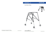
Figure 1-2 - Activity Chamber Setup
Additional chambers are connected via their ENV-520s controllers with SG-219C control
cables, starting at Chamber #1 and proceeding in sequence, in a daisy chain fashion.
For example, if there are four chambers, Chamber #1 connects to Chamber #2, Chamber
#2 connects to Chamber #3, and finally Chamber #3 connects to Chamber #4. Ensure
each connector is securely attached to the ENV-520 by tightening the screws on the
cable. Connect the power cords from all ENV-520s to the SG-506 power supply. See
Chapter 3 for a quick hardware test utility that can be run to verify proper operation of
all photo beams before actually running an experiment.
MED Associates assembles equipment prior to shipment.
The ribbon cables are
connected from the ENV-520 to the I/R Array Strips as shown in Figure 1-2. The
corresponding receiver strips are located directly opposite the transmitter strips.
-2 -
MED ASSOCIATES INC.
ACTIVITY MONITOR
Figure 1-3 - Activity Chamber with Hole Board Insert
•
Hole Board Transmitters 1 and 2 connect to the “Transmitter 3” port on the ENV520 Controller.
•
Hole Board Receivers 1 and 2 connect to the “Receiver 3” port.
•
Transmitter 1 gets connected to the “Transmitter 1” port.
•
Transmitter 2 gets connected to the “Transmitter 2” port.
•
Receiver 1 gets connected to the “Receiver 1” port.
•
Receiver 2 gets connected to the “Receiver 2” port.
An easy way to check that the I/R Array Strips are correctly connected is to run a quick
one-minute test experiment. Place an object into the test chamber and confirm that the
red dot on the run-time screen is tracking correctly (i.e., back left in the chamber should
be top left on the screen and front right in the chamber should be bottom right on the
screen).
-3 -
MED ASSOCIATES INC.
ACTIVITY MONITOR
Modifying I/R Array Height
Do not assume that the factory set I/R Array heights are appropriate for the experiments
being run. Different ages and strains of subjects may have vastly different physical
characteristics. Also, because we have developed inserts (Chapter 5) to increase the
system’s functionality, the I/R Array strip heights from the environment floor may need
to be adjusted.
The closer the I/R Array strips are placed toward the subjects' vertical center (for X & Y
arrays), the better the data. If a subject is too low for the I/R strips, or capable of
"crouching" periodically below the strips, the subject may disappear from "sight" of the
system from time to time. The software is designed to remember the last location and
pick back up when the subject becomes "visible" again. Typically, this will have little
bearing on the data; however, if using Velocity data, there could be a sudden increase in
a subjects' velocity and Jump Counts and Time will be affected. There may be other
scenarios whereby inaccurate I/R strip placement may present erroneous data, so use
care in this process.
The "Z" I/R Array strips should be placed in the lowest available position capable of
detecting vertical activity and not detecting normal "X" & "Y" activity. If the strips are
too high, some rearings may not be detected, or slight "bouncing" while rearing may
cause multiple rearings to be detected when only one rearing episode was indeed
elicited.
-4 -
MED ASSOCIATES INC.
ACTIVITY MONITOR
CHAPTER 2
Getting Started
General Software Information
Data analysis has been taken to an entirely new level with the addition of such measures
as rotational behaviors, zone entries, jumping, etc. (Appendix II) added to the system.
Data acquired on systems using Version 3.0 or higher may be reanalyzed in this version
to obtain these new measures. The analysis parameters may be changed and the data
re-analyzed to extract additional information.
The Activity Monitor is designed for use with MED Associates hardware to collect, plot,
and analyze activity data. All standard data is displayed in real-time, along with a
cumulative plot of the subject's activity. The data acquisition configuration files, which
specify the state of the system (Resolution/Sample Rates, Ambulatory/Stereotypic
Movement definitions), are stored in filename.CFG files. The default settings are userdefined and determined the very first time that the Activity Monitor software is run. See
Chapter 3, for Configuration File set up.
In addition to providing the database to store all experiment and subject data and
information, we have also provided the option to create an ASCII text and a "hard copy"
printed summary data file automatically. After each subjects’ session or after each
experiment (multiple subjects), the software can print the summary data automatically
and save a summary data file for each subject, simply by checking the appropriate check
boxes in the preference settings window (Figure 3-3). Likewise, analyzed data and Raw
Point data ASCII text files may also be generated aside from the database file. All ASCII
text files are named according to the file-naming scheme presented in Table 3-4 and
discussed in Appendix I.
There are two database files created by the Activity Monitor software: EXP.MDB and
ANALYSIS.MDB. These files are Access ® database files, but may be opened with many
database programs.
In order to extract precisely formatted data, they must be
manipulated or sorted with a database program that can open a standard Access ®
scheme. We have opted to create this database to enable researchers to export an
entire experiments worth of analyzed data, sorted and defined, into a spreadsheet to
make Subject, Group, and Experiment data analysis simple and fast.
Introduction to Open-Field Activity Monitoring
Open-Field Activity (OFA) monitoring is a sensitive method of measuring both gross and
fine locomotor activity in small animals. In general, computerized OFA characterizes
multiple end points of motor behavior, and has proven to be a powerful assessment tool
with many applications in behavioral pharmacology, toxicology, and genetics. For
example, dopamine agonist studies can use distance traveled in centimeters as a
measure of gross motor activity that is amenable to quantitative analysis. Opiate
tolerance studies can examine overall distance traveled, but can also utilize time and
distance in the margin of the chamber as well. Anxiety can also be characterized with an
-5 -
MED ASSOCIATES INC.
ACTIVITY MONITOR
OFA system using the above mentioned thigmotaxis measure and by examining patterns
of exploration in a brightly lit arena with a dark area (See Dark Box Insert – Light/Dark
Conflict Test). In addition, other models with proven construct validity, such as the hole
board task and place preference, can also be performed with the MED Associates’
System. These add-on components make the MED Associates’ OFA system very versatile
and an excellent value for laboratories that are both space and cost conscience.
Two standard sized environments, the ENV-510, 10.75" X 10.75" X 8" H (27 X 27 X 20.3
cm) and the ENV-515, 17" X 17" X 12" H (43.2 X 43.2 X 30.5 cm) are suitable for mouse
and rat protocols, respectively.
The system consists of a subject containment
environment (chamber), infrared (I/R) sources and sensors, a system power supply, an
environment data source controller, appropriate connecting cables, a PC/environment
interface card, and the data acquisition/analysis software. Subject location is tracked
using 16 evenly spaced I/R sources and sensors juxtaposed around the periphery of the
four sides of the chamber. This I/R beam array defines an X and Y coordinate "map" for
the system. The sensors detect the presence or absence of the I/R beam (i.e., the
subject) at these corresponding coordinates.
At user defined time intervals, the software has instructions to “poll” the environment for
the presence or absence of the I/R beam at each sensor. This is the scanning rate or
sampling rate of the system. If the I/R beam fails to reach the sensor, the system
registers this event as a broken beam and assumes the presence of the subject. Broken
beams at X 1,2,3,4 and Y 2,3,4,5 are averaged, with the resulting microprocessor derived
coordinate being X = 2.5 and Y = 3.5 or just 2.5, 3.5. The averaged beam breaks or
subject "centers" are the data that the software algorithms use to derive the behavioral
parameters such as distance traveled and time spent in a given zone. The software thus
has a resolution of 32 x 32.
By scanning or “polling” the environment many times a second, the OFA system can
effectively track the movement of a subject very precisely. The faster the scanning rate,
the greater the accuracy of the system for high speed behavioral measures such as
stereotypic behaviors, as well as for event-related, time-sorted data.
We offer variable scanning rates to accommodate personal preferences (
Table 3-1). Many researchers feel that there are few advantages to faster scanning rates
for long trial runs where the data of interest does not require the increased rates. After
all, faster scanning rates mean larger data files and longer post-hoc data analysis
processing times.
For such researchers, we have designed the software so that measurements may be
taken as small samples, repeated at preset intervals (
Table 3-1). This allows for focused data files and virtually eliminates the need to sort
through large quantities of data to extract the desired measures. Experience in this
matter will help to determine the test type, continuous or segmented, and the scanning
rate that is best for the application.
The addition of a photo beam array above a subject adds a second plane of detection to
the system. This is used to detect the presence or absence of a subject in this plane.
The "Z" coordinate is used to detect rearing or standing on the hind legs.
-6 -
MED ASSOCIATES INC.
ACTIVITY MONITOR
The menu selections are outlined in the next chapter. The above general system and
open-field information will assist with understanding what the menu selections mean and
why they are important.
-7 -
MED ASSOCIATES INC.
ACTIVITY MONITOR
CHAPTER 3
Menu Options
To run the Activity Monitor, select the Activity Monitor program group and double click on
the Activity Monitor icon. The main Activity Monitor screen appears with a copyright
screen that disappears after a few seconds (Figure 3-1).
Figure 3-1 - Activity Monitor Copyright Screen
The main Activity window is now displayed. This window is blank. There is a menu
displayed across the top of the window with all the software functions that are accessible
within this blank window.
File Menu Options
Preferences
Select File | Preferences to setup the configuration file to match the system and
the particular experiments. Parameters do not need to be entered every time an
experiment is run. The default settings are user-defined and are determined the
very first time that the Activity Monitor software is run.
The filename.CFG file controls how the software acquires the data, from the
system-sampling rate to where the raw data files are to be located. The raw data
is compressed in a filename.ZIP file automatically. Within this ZIP file are the
raw binary data files that are named according to the date on which they were
created (mmddyyyyA0 - Z99, i.e. 01012003.A0 (January 1, 2003), and are linked
to their appropriate subjects’ data file. These are the files used by the system for
playback and analysis. The settings in the Preferences window may be changed
at any time but may change the nature of summary data. Therefore it is not
recommended that these settings be changed in the middle of running an
experiment until this manual has been read. Experiment configuration settings,
however, may not be changed in the middle of an experiment.
-8 -
MED ASSOCIATES INC.
ACTIVITY MONITOR
Figure 3-2 - File Pulldown Menu
Figure 3-3 - Preferences Screen
NOTE:
Changes to the Chamber Model, Units, and Include Resting Delay will change
Summary Data measures, making them inconsistent.
Use caution.
This
information is coupled with the Experiment Configuration File information to
determine how the software records the data and where it stores the files, but
is independent in that these settings may be changed in the middle of an
experiment.
-9 -
MED ASSOCIATES INC.
ACTIVITY MONITOR
Following installation, the default configuration must be set up such that the software
has the necessary information to begin acquiring data. The information entered in the
Preferences window must reflect the system. In this manner, the default settings will
match each individual system exactly.
The preferences screen requires the following information:
Table 3-1 - Preference Configuration Options
Item
Data Directory
Name:
Description
The directory to store the data (*.ZIP) files. If unsure which directory to use, use the
browse button. A subdirectory named DATA in the Activity Monitor directory is advised
and must be created first. Also, this directory will also be the location of the database
files (EXP.MDB and ANALYSIS.MDB), Summary, and Zone Analysis text files will be
located.
The program has been developed to create the database(s) and *.ZIP files in the chosen
directory.
This allows multiple users to have their own separate database of
experiments. See Appendix V for details.
Data Reporting
Mode:
In Absolute mode each time bin holds the sum of all data since the experiment began.
The Relative mode each time bin holds the sum of the data since the last time bin.
A = Absolute
R = Relative
The Data Reporting mode affects how the data looks when it is sent to the printer and
how the data looks in the Summary data file. It is also used to determine how the data
will be presented in the Analyzed data files.
Display Time in
Hours
When checked, time is displayed as hours:minutes:seconds (000:00:00.00).
unchecked time is displayed in minutes as minutes:seconds (0000:00.00).
Units
The units of measure, centimeters or inches, that distance data will be displayed in.
Number of
Chambers
The number of test chambers being used (1 – 8).
number one and proceed in sequence (Chapter 1).
Chamber Models
If
The test chambers always start at
Provides the chamber product number:
ENV-510 for 10.75” X 10.75” (mouse) chambers with 16 beams
ENV-515-16 for 17” X 17” (rat) chambers with 16 beams
ENV-515-32 for 17” X 17” (rat) chambers with 32 beams
VID-510 for 10.75” X 10.75” (mouse) chambers for use with Video Tracking Interface
VID-515 for 17” X 17” (rat) chambers for use with Video Tracking Interface
VID-410 for 7” X 9.5” (mouse) home cages to be used with Video Tracking Interface
VID-415 for 8” X 17” (rat) home cages to be used with Video Tracking Interface
It is important that the correct chamber is selected so that distance traveled data is
calculated correctly. Different sized chambers may be used at the same time.
Print
These check boxes are used to automatically activate printing using the self-explanatory
options:
Off (do not print the data file)
Session End (print the data file after each subject is run)
Experiment End (print the data file when Run | Close Experiment is selected)
Justify
If Right is chosen, then all data will be right justified in its field.
If Left is chosen, then all data will be left justified in its field.
This can sometimes make it easier to import data into a spreadsheet program.
- 10 -
MED ASSOCIATES INC.
Item
ACTIVITY MONITOR
Description
Include Resting
Delay
As detailed in Appendix IV, the "Box" serves three primary functions; in particular, to
filter movement data for a more precise distance traveled measure. Activation of this
check box removes the filtering from the distance-traveled measure. This box should not
be checked unless attempting to duplicate data that was generated on a system that
does not have this "filtering" capability.
Generate
Summary File
This option creates an ASCII text summary file that will be automatically saved in the
data directory. If the Automatic File Naming option is turned on, then the file name is
generated automatically from the values entered into the Subject, Experiment, and
Group fields on the “Run Experiment” screen. The file will also have the extension
“SUMMARY.” This option allows the user to store to disk the summary data, which may
also be printed, for backup. Every time that a subject is run, the new summary data is
appended to the existing file.
Automatic File
Naming
Creates data filenames according to the file-naming scheme presented in Appendix I. If
this check box is not selected, the User must manually enter a file name.
Start on Animal
Entry
Enables the system to begin a session as soon as the subject is placed into the chamber
and the first sets of photobeams have been broken. This is a very nice feature for the
hole board test and for starting sessions when the computer is in another room. This
feature cannot be used with Video Tracking Interface.
Start on Remote
Start
Enables the system to begin a session as soon as the Remote Start Event for that
chamber has been set. This allows 3 rd -party programs (like MED-PC IV) to remotely start
the Activity chambers. If both “Start on Animal Entry” and “Start on Remote Start” are
checked, the chamber will not start until it has received a Remote Start Event and the
animal is present in the chamber. See Appendix VIII for more information on the
Remote Start command.
Use Video
Tracker
This feature must be enabled to allow collection by Activity Monitor of video tracking
data captured via the Video Tracking Interface program.
Select Computer
Source
When collecting data via the Video Tracking Interface (VTI), this option selects the
computer that the VTI program is running on. In Windows 98, this information must be
manually entered (typed); For example, if the VTI software is running on the computer
“video”, then enter the text
\\video
In Windows 2000 or XP, click on the
“Select Computer Source” button to browse for the appropriate computer. If Activity
Monitor is running on the same computer as VTI then clicking on “My Network Places”
and clicking OK will set the computer to itself, as shown in Figure 3-3 .
Chamber Models
Activity Monitor can acquire data for eight different test subjects simultaneously,
as indicated by the drop down menus numbered 1 – 8 in the “Chamber Models”
field of the Activity Monitor preferences screen shown in Figure 3-3. Video
Tracking Interface (VTI) can acquire data from four cameras, depending upon the
capabilities of the computer, and each camera can track either one, two or four
animals depending upon the type of chamber/cage platform being used: VID-515,
single rat activity chamber; VID-510, dual mouse activity chambers; VID-415,
dual rat home cages; VID-410, quad mouse home cages.
When Activity Monitor is using VTI to acquire data, the chamber model used for
each test subject (1 – 8, as appropriate) needs to be set in the Chamber Model
field of the Activity Monitor preferences screen. The chamber model is dictated
by the number of cameras VTI is using and also by the chamber/cage platform
used.
- 11 -
MED ASSOCIATES INC.
ACTIVITY MONITOR
VID-515 acquires data from one animal per camera, so for a two-camera setup
chambers one and two should be set to VID-515.
VID-510 acquires data from two animals per camera, so for a two-camera setup
chambers one through four should be set to VID-510.
VID-415 acquires data from two animals per camera, so for a two-camera setup
chambers one through four should be set to VID-415.
VID-410 acquires data from four animals per camera, so for a two-camera setup
chambers one through eight should be set to VID-410.
Data Analysis
The File | Data Analysis option brings up a listing of data files for analysis or
re-analysis. The data files are in the database EXP.MDB and are separated by
Experiment ID. Clicking on the corresponding experiment (top list in Figure 3-4)
and scrolling through the individual subject data sets (bottom list Figure 3-4) until
the desired subject/session data is found can find a specific data set/session.
Figure 3-4 shows the screen displayed when the Data Analysis menu option is
selected. Chapter 4, has the necessary details to analyze the data. To select
data to be analyzed, simply click on the subject/file name on the lower half of the
screen display to activate that file. Use the Shift key to select more than one file
to analyze. Column widths may be resized using the mouse in the header
column.
Figure 3-4 - Data Analysis Database Window
- 12 -
MED ASSOCIATES INC.
ACTIVITY MONITOR
Experiment Maintenance
File | Experiment Maintenance menu option allows viewing, printing, and
deleting of the information in the database (Figure 3-5).
Clicking on the
corresponding experiment (top list in Figure 3-5) and scrolling through the
individual subject data sets (bottom list Figure 3-5) until the desired
subject/session data is found can find a specific data set/session. To delete the
data, left mouse click on the corresponding line. It will become outlined, then
click the delete button. Column widths may be resized using the mouse in the
header column.
The Print button can be used to reprint the Summary data file that was created
when the experiment was first run. The data can be printed in either Relative or
Absolute mode. If the data has been imported from a zip file, then it is not
possible to reprint the Summary data file.
Figure 3-5 - Experiment Maintenance Window
- 13 -
MED ASSOCIATES INC.
ACTIVITY MONITOR
Import Data
The File | Import Data option allows the user to import data acquired with this
version and earlier versions of the Activity Monitor software, store the data in the
database, and analyze this data with the latest measures. Import multiple *.ZIP
files simply by using the Shift or Ctrl keys when selecting the files. Like data files
that are created when an experiment is run, data files that are imported are
reformatted and stored in the raw data *.ZIP file.
Export Data
The File | Export Data option allows an Activity data file to be selected and the
point data saved as an ASCII text file with a filename generated according to the
Data Filename scheme presented in Table 3-3, with a EXPORT extension. This
utility is available for those researchers who wish to analyze data by writing a
program in Visual Basic or some other language. Once a pattern is identified, the
only way to extract very complex behaviors may be to do custom programming.
MED Associates designs software with the most often used measures, but certain
researchers may be interested in a particular behavior that only a few are
knowledgeable enough to discern and differentiate. This can be done with ASCII
point data. After selecting a data file, the Save Raw Data screen (Figure 3-6)
appears. Click on the file to export. Another screen then displays (Figure 3-7)
and requests the following information:
Table 3-3 - Saving Point Data as an ASCII File
Item
Description
Annotated File /
Stripped File
Select the type of file output. The annotated file includes the experiment header
information. The stripped file only includes the point data information. When
importing information into a spreadsheet it is advisable to include the annotated file
for the first data file and stripped files for each subsequent file.
Time:
Select the time period, in minutes to include in this file. Any part of a session or the
entire session may be specified. This is typically used to save time by allowing
specific sections of the data to be exported as determined during data analysis to
view time sequenced data measures
Save As
Clicking on this button will bring up a Save As file screen so the filename for the
point data may be entered.
Cancel
Exits the Save Raw Data screen without saving the data.
- 14 -
MED ASSOCIATES INC.
ACTIVITY MONITOR
Figure 3-6 - Export Raw Data Screen
Figure 3-7 - Save Raw Data Screen
- 15 -
MED ASSOCIATES INC.
ACTIVITY MONITOR
ENV-520 Test...
This menu option provides a graphical interface for testing the ENV-520
controller, photo beam strips, and the interrupt on the DIG-729 card for each
chamber (Figure 3-8) and for all chambers simultaneously (Figure 3-9). This can
also be used to test if the Video Tracking Interface (VTI) system is working
properly. To test the VTI system, please be sure that the Preferences menu is set
to Use Video Tracking, and that the appropriate computer is selected. Then
start capturing data on the VTI system. Once this is done the ENV-520 Test can
be run. This ensures that the equipment is in proper working order and identifies
where hardware problems may be occurring. Should there be problems with the
system, contact MED Associates for troubleshooting help.
This test should be run when the equipment is set up, and if using the DIG-729,
before every session. First run the multi-chamber test by checking the Display
Raw Values check box. Make sure that there are no subjects in the chambers.
Click start. If the X, Y, or Z values are any number other than zero, check for
obstructed photo beams. The number of beam breaks should be zero. If there
are multiple beam breaks on the X, Y, or Z-axis when no subjects are in the
chamber please contact MED Associates. If there are many chambers (nodes)
with values other than zero, contact MED Associates.
Table 3-4 - ENV-520 Hardware Test Utility
Item
Description
Select Chamber
Select the chamber number to test. Only 1 chamber can be tested at a time.
Display Raw Values
This allows the viewing of the bit values for all chambers simultaneously.
Tick Count
Time increments
Start
Click this button to start the test. Photo beams that are blocked or not functioning,
displays as a red dot. Functioning photo beams display with a gray dot.
Stop
Clicking on this button stops the interrupt and stops displaying data.
Exit
Exits the ENV-520 Test screen.
- 16 -
MED ASSOCIATES INC.
ACTIVITY MONITOR
Figure 3-8 – ENV-520 Test Screen to Isolate Blocked or Non-Functioning Photobeams
Figure 3-9 - ENV-520 Test Screen for All Chambers.
- 17 -
MED ASSOCIATES INC.
ACTIVITY MONITOR
Print
The Print option is only available after an experiment is completed or after data
has just been analyzed. Different menu options are available depending on
whether an experiment finished or data was played back.
Figure 3-10 - Print Options Are Available After Running and Experiment or Analyzing Data
Session Data
Available only after an experiment is complete, this menu option prints the
selected chambers' summary data files to the Windows default printer.
This option may also be activated to automatically print by selecting the
Print on Session End or Experiment End radio button on the File |
Preferences screen (Figure 3-3).
Data Windows
Available after an experiment is complete or after a data analysis, this
menu option prints the selected chambers' data windows to the Windows
default printer.
Graph Windows
Available after an experiment finishes or after a data analysis, this menu
option prints all the chambers' graph windows to the Windows default
printer.
Exit
This exits the Activity Monitor program. If an experiment is running, the data
saves and prints in the same fashion as canceling an experiment.
- 18 -
MED ASSOCIATES INC.
ACTIVITY MONITOR
View Menu Options
These three options are used to determine how the subjects' activity displays graphically
in the real-time display of activity and in the data analysis utility of the software, should
Display Grid During Analysis be activated.
Figure 3-11 - View Pulldown Menu
Line Trace
This is the default plotting option. It plots a dot as the center of the subject and
draws a line showing all movement.
Box Plot
This option shows the stereotypic box around the dot that represents the center
of the subject. The subject can be seen moving within the box during stereotypic
movements. When the subject becomes ambulatory, the box moves to the new
center of the subject.
Dot
This option plots just the dot that represents the center of the subject.
View Summary File
This option will open and allow the user to view the contents of the summary
data files (files that have the SUMMARY extension).
View Analysis File
This option will open and allow the user to view the contents of the data analysis
files (files that have the ZONE extension.
- 19 -
MED ASSOCIATES INC.
ACTIVITY MONITOR
View Export File
This option will open and allow the user to view the contents of the exported data
files (files that have the EXPORT extension.
Run Menu Options
Figure 3-12 - Run Menu Options
Open Experiment
Select Run | Open Experiment to display the Run Experiment window that is
the heart of this program. The Run Experiment screen (Figure 3-13) is the
interface for the database(s) mediating experiment and subject data acquisition
and storage. Since the Open Experiment menu option is actually the first in a
series toward running the experiment, the majority of the associated information
can be found in Chapter 6.
- 20 -
MED ASSOCIATES INC.
ACTIVITY MONITOR
Figure 3-13 - Run Experiment Screen
- 21 -
MED ASSOCIATES INC.
ACTIVITY MONITOR
The Run Experiment screen requires the following information:
Table 3-4 - Experiment Database and Run Screen
Item
Description
Current
configuration: *
The current system configuration filename is displayed at the top of the experiment
setup screen when creating a new experiment. It is important to note that once an
experiment is started with a specific configuration, most parameters may not be
changed “mid-stream” so that continuity is maintained throughout an experiment.
Experiment ID: *
The Experiment ID may be up to 25 characters and is used for both the Data
Filename (below and Appendix I) and as a link throughout the database to sort data
accordingly. This field is used to automatically generate the Data Filename (below).
There is a drop down menu associated with the Experiment ID. The second time
that an experiment is run, simply select from the drop down menu the experiment to
be run. The database is now loaded with the appropriate subjects' information and
experiment configuration parameters.
Experiment Title: *
Experiment title may be up to 25 characters. This is a descriptor field for the
Experiment ID. When the Data Analysis or Experiment Maintenance windows is
opened, the Experiment Title is visible. This description of the experiment is present
to allow the user to visualize which data sets may be selected for analysis, reanalysis, deletion, etc.
Experiment
Comment: *
Maintained for database purposes and allows the user to add additional information
pertaining to a given experiment.
*
These fields are experiment specific in nature. The information entered here is
included in the database for all subjects run under this Experiment ID and Title.
These subjects’ data will also have been collected using the stated configuration file
and will have the added experiment Comment.
Box # 1 - 8 Index
Card Tab††
Activates the particular chambers' data entry screen. The active screen's
information is subject/chamber specific in nature and is logged accordingly in the
database.
Subject ID:
†
Subject identifier, with 25 available characters. This field is used to automatically
generate the Data Filename (below). There is a drop down menu associated with
the Subject ID. The second time that an experiment session is run, simply select
from the drop down menu the subject to be placed in the corresponding chamber.
The database is now loaded with the appropriate subject’s session number and all
corresponding information.
Group ID: †
Used as an identifier, with 25 available characters, and is linked to the Subject ID
the first time that a subject is run in an experiment. This field is used to
automatically generate the Data Filename (below).
Session Comment: †
All comments entered in this screen are subject specific in nature and are added to
each subjects' session data file.
Data Filename: †
All data filenames are generated using the Subject ID, the Group ID, and Experiment
ID. See Appendix I for details. If automatic file naming is turned off a filename
may be entered.
- 22 -
MED ASSOCIATES INC.
Item
Start Box
ACTIVITY MONITOR
Description
††
Used to tell the software to start the chamber when OK is clicked. If the Start on
Animal Entry check box is activated in the Preferences screen and saved in the
current *.CFG file, then the session begins as soon as the subject is placed into the
chamber and the first photo beams are broken.
Session Number
Enter the session number in this field.
Copy Data to All
Chambers
Copies the information in the current screen to all the other chambers. All data is
copied except the Subject ID.
Clear Data
Clears all the data fields.
OK
If the Start Box check box is activated, closes the Chamber ID screen and starts the
chambers.
Cancel
Closes the Run Experiment screen without running the experiment and deletes and
chamber/subject specific information entered.
Add New Experiment
Clicking this button brings up the screen shown in Figure 3-14 . Experiment
Configuration sets data acquisition and ambulatory data parameters. Included in the
Experiment Configuration File are the settings necessary to run a Hole Board test
and to choose session type.
†
Subject specific in nature and added to a given subjects data file accordingly. This
information is only linked to chamber specific information for a given session.
††
These fields are chamber specific in nature and reflect the state of a given chamber
during a given session.
- 23 -
MED ASSOCIATES INC.
ACTIVITY MONITOR
Add New Experiment
Selecting Add New Experiment from the Run Experiment menu causes the
screen shown in Figure 3-14 to appear. These settings may be modified in Data
Analysis to examine the parameters in greater detail.
Included in the
experiment configuration file is the Hole Board Task definition. See Chapter 7,
for more information.
Figure 3-14 - Experiment Configuration
By saving the entered settings using the Save As or OK buttons as
DEFAULT.CFG, the first experiment is ready to be run using these settings. It is
recommended that file names for configuration files reflect the protocol that is
to be run. For example, changes in Box Size, Ambulatory Trigger, and Resting
Delay for use in amphetamine studies could have a filename that reflects its
usage, like Amphetamine_Box_Size.CFG. DEFAULT.CFG should be used for the
first practice experiment and kept on the computer in the Activity Monitor
directory. It is important to note that once an experiment is started with a
specific configuration, it may not be changed “mid-stream” so that continuity is
maintained throughout an experiment.
- 24 -
MED ASSOCIATES INC.
ACTIVITY MONITOR
The Experiment Configuration screens require the following information:
Table 3-6 - Experiment Configuration Information
Item
Resolution (ms)
min - 25
max – 250
Description
The rate that the Activity Monitor acquires the data from the test chambers. This rate is
user-definable to enable variable data acquisition rates; thus, minimizing file size, or
maximizing resolution, depending upon the type of data sought and the size of the hard
drive. Larger data files require more disk space and longer analysis times. This rate is
automatically set to 33 1/3 ms when using the Video Tracking Interface system.
This setting is a vestige of days gone by when hard disk size and memory were limiting
factors. It is recommended that 50 ms or less be used if using a new computer with
plenty of disk space.
Box Size (beams)
min - 1
max – 8
Box size serves three primary functions:
One, to delineate the maximum area that a subject may move within, and after the
Resting Delay (ms) criteria has been met (below), to have each movement measures as a
Stereotypic Count. If stereotypic is the primary measure, the size of the Box should be
set to the maximum distance that the stereotypic behavior would attain without leaving
(i.e. grooming could use a Box Size of 2 or 3 and head weaving could use a Box Size of 3
or 4).
Two, to "filter" movement data so that distance-traveled measures do not include
"bouncing" or "flickering" artifacts.
Three, the Box Size, Ambulatory Trigger and Resting Delay settings combine to create
a threshold whereby a subject must move a certain distance (Box Size) in a maximum
amount of time (Resting Delay) to maintain its ambulatory status. This is actually a
method to define large (ambulatory/quick) and small (stereotypic/slow) movements. See
Appendix IV. Standardized settings are not available, but would be dependent upon the
application being used (ataxic vs. non-ataxic subjects) and the strain of mice being
studied.
Box size can be changed in Data Analysis.
Resting Delay (ms)
min - 50
max - 2000
The Resting Delay is the amount of time the subject has to pass through the box (above)
to maintain its ambulatory status, or to make another ambulatory movement after the last
ambulatory movement. See Appendix IV.
Resting Delay can be changed in Data Analysis.
Ambulatory Trigger
The number of beam breaks, after leaving the box, necessary to initiate an ambulatory
episode and to have the ambulatory distance considered in the Velocity measure.
Session Type (C, S)
Select "C" for a Continuous session. Select "S" for a Segmented session. If a Segmented
session is chosen, the configuration screen changes.
Session Time (min)
The amount of time for the session to run.
Block Interval (sec.)
The size of the Blocks (time bins) that the data are to be broken down into in the
summary data files and the data that will be sent to the printer.
This may be changed in Data Analysis.
Compressed File
Name of the ZIP file to store the raw data. If an extension is given, it will be ignored.
See Appendix I. See Appendix V for multiple users and *.ZIP files.
- 25 -
MED ASSOCIATES INC.
ACTIVITY MONITOR
Item
Description
Hole Board Floor
Installed
This option must be checked if the Hole Board Insert is being used. Please note that the
Video Tracking Interface does not support the Hole Board.
Hole Board Strips
Installed
This option must be checked if the Hole Board I/R (4 x 4) arrays are being used to run the
Hole Board Task test and the “X” and “Y” photo beams are being used to monitor general
activity.
Define Task Floor
Click to view task definition screen ( Figure 7-4 ).
Load
This option allows the selection of the experiment configuration file that will be used by
the program to determine the data properties.
Save
Saves the present configuration information to the already named filename.CFG. For new
configurations, use the Save As option.
Save As...
Brings up a Save As window a filename may be specified. When setting up the software
for the first time, use the DEFAULT.CFG file name specified in the Save As window.
OK
After loading, changing existing, or creating new *.CFG files, this option allows the exiting
of the Experiment Configuration File window.
Cancel
Exits the configuration screen without saving the information.
Close Experiment
Select Run | Close Experiment to abort a running experiment or close the runscreen when all subjects have finished. If print data at the end of an experiment
(Figure 3-3) has been selected, this is when the summary data file will print. All
the data that has been collected up until the time that the experiment was
canceled, if still active, saves in the file names specified during Experiment Setup
(Table 3-6 and Appendix I). If aborted experiment data files need to be deleted,
it is best to do so immediately via the Experiment Maintenance window (Figure
3-5).
Start
The Run | Start option displays the Run Experiment screen (Figure 3-13), where
the subject specific and chamber specific information is entered. Clicking OK then
starts the session.
There are two Start options available while the experiment is running. Both are
context sensitive in that the Start Windows pull down menu option and the Start
right mouse click menu options are active window specific. For example, if there
is eight chamber windows displayed and start is selected from the pull down
menu, one of the box index tabs will be prominent. Viewing the chamber number
in the mid-left side of the window indicates which window is active. The active
chambers' window has a more prominent number than the other chamber
numbers. That box depicts the active window of the eight. Clicking on a
chamber display window and then selecting Start from the Run pull down menu
causes that chamber (box) to be the prominent chamber (box) displayed in the
Run Experiment screen. Likewise with the right mouse click menu, the computer
- 26 -
MED ASSOCIATES INC.
ACTIVITY MONITOR
mouse is placed over a specific chamber' display window and right mouse click,
that chamber will be the selected chamber when Start is clicked.
Cancel
The Run | Cancel option cancels selected active chambers’ sessions. This is the
same as closing an experiment except that only the selected chambers’ session is
canceled. The data that was acquired up until the time the cancel was initiated
saves to the corresponding subjects' file. Session data may be deleted using the
Experiment Maintenance utility (Figure 3-5).
Pause
The Run | Pause option allows the user to pause a chambers' data acquisition,
for whatever reason, and resume (below) when applicable.
Resume
The Run | Resume option resumes a paused chamber (above).
Window Menu Options
Tile
Arranges the windows in a tile fashion.
Maximize
Maximizes the active chamber’s display window.
Restore
Restores the chamber-display windows to tiled.
Help Menu Options
Index
Opens the Activity Monitor Help file and brings up the index.
Using Help
Opens Window's How to Use Help file.
About Activity
Displays the Activity Monitor copyright and version screen.
- 27 -
MED ASSOCIATES INC.
ACTIVITY MONITOR
CHAPTER 4
Data Analysis Menu Options
Data Analysis Setup
Figure 4-1 - Data Analysis Database Window
After running an experiment, select File | Data Analysis to view a listing of experiment
and subject/session data files (Figure 4-1). Once the appropriate experiment and subject
have been selected, click on the OK button and the Data Analysis screen appears (Figure
4-2). This screen is divided into three categories, General, Zone Calculations, and
Rotational Calculations. This screen displays selected analysis numbers and check
box annotations, which are set in the associated Select Definition windows of the
program (Figure 4-8 - Figure 4-10).
Figure 4-2 - Data Analysis Screen
- 28 -
MED ASSOCIATES INC.
ACTIVITY MONITOR
There are five check boxes that control the following:
Table 4-1 - Data Analysis File (Display and Analysis Sections)
Item
Rotational Analysis
Description
Activates the select definition bar to define the rotational behavioral analysis. These
parameters are defined in the corresponding Select Definitions display window
(Figure 4-8 - Figure 4-10) . Activation of the check box increases the analysis time
considerably.
Zone Analysis
Activates the select definition bar to define the zone analysis. These parameters are
defined in the corresponding Select Definitions display window ( Figure 4-5 – Figure
4-7 ).
Display Grid
View subject movement graphics and the associated measures while the data are
being analyzed. This is nice to see when the program is first run; however, when
analyzing multiple data sets (perhaps 100s), this feature slows down the analysis time
considerably. It also allows movement plot graphics to be printed at the end of the
analysis.
Write Summary File
Automatically generate an ASCII text file of the analysis data. These summary
analysis data files are named according to the file naming structure. Every time that
a subject is run and the data is analyzed or re-analyzed, the associated data
measures are appended to the file. These data are always in the common subject
data file. The same analysis information is also present in the ANALYSIS.MDB
database file.
Create Database
Entries
Create ANALYSIS.MDB database entries of the analyzed measures. Both ASCII text
and database files are generated if both Write Summary File and Create Database
Entries check boxes are activated.
- 29 -
MED ASSOCIATES INC.
ACTIVITY MONITOR
General Analysis Information
Figure 4-3 - General Analysis - Continuous Experiments
Figure 4-4 - General Analysis - Segmented Experiments
The first Select Definition grouping is the General Analysis group. These parameters
were established in the Experiment Configuration setup, but may be modified for data
analysis.
The following parameters may be changed in the General Analysis section:
Table 4-2 - General Data Analysis
Item
Start Time
default - 0
End Time
default - end time
Sample Number
Description
Select the minute to start the data analysis from. The default and recommended
setting for first time data analysis is 0. Like End Time, listed below, this feature
is useful primarily only after data has already been analyzed and specific time
bins need to be further defined.
Select the minute that the data analysis should stop. The default is the end of
the protocol. This feature is useful primarily after data has already been analyzed
and specific time bins need to be further defined and analyzed using, usually,
smaller time blocks.
If a segmented experiment was run, then the Sample Number option will appear
instead of the Start Time and End Time options. The Sample Number option
allows for selection of which segment to analyze.
- 30 -
MED ASSOCIATES INC.
ACTIVITY MONITOR
Item
Description
Data Block Interval
Data may be analyzed as a series of time blocks. This feature is useful for
examining instantaneous values (1 sec) or larger to determine time sequenced or
event related values. A summary total of all of the data blocks is always provided
in the output data file. This interval is independent from the interval set in the
Experiment Configuration screen in that this value may be changed for each data
file re-analysis. The Experiment Configuration Block Interval is used only for
summary and print data.
Sec.
Data Blocks
Numeric
Box Size (beams)
min - 2
max – 8
The number of Data Blocks is established when the analysis time (entire session
or a portion there of as defined by the Start and End Time listed above) is broken
up by the Data Block Interval.
Box Size serves three primary functions:
One, to delineate the maximum area that a subject may move within, and after
the Resting Delay (ms) criteria has been met (below), to have each movement
counted as a stereotypic movement.
Two, to "filter" movement data (Appendix IV).
Three, the Box Size and Resting Delay settings combine to create a threshold
whereby a subject must move a certain distance (Box Size) in a maximum amount
of time (Resting Delay) to maintain its ambulatory status.
Resting Delay (ms)
min - 50
max - 2000
Ambulatory Trigger
The Resting Delay is the amount of time the subject has to pass through the box
(above) to maintain its ambulatory status, or to make another ambulatory
movement after the last ambulatory movement. See Appendix IV.
The number of beam breaks, after leaving the box, necessary to initiate an
ambulatory episode and to have the ambulatory distance considered in the
Velocity measure. See Appendix IV.
- 31 -
MED ASSOCIATES INC.
ACTIVITY MONITOR
Zone Analysis
The Zone Setup screen allows the user to define the X and Y coordinates of the zones to
be analyzed. All of the behavioral measures will then be determined for each zone, as
well as totals for all zones. Up to 4 zones plus 1 residual zone may be created or
selected (Figure 4-5). A number of preset zone options have been provided. They
include Horizontal, Vertical, Quadrant, Corner, and a number of user-definable, and
savable, spaces for custom zones (Figure 4-6). The zones defined must be rectangular in
shape and cannot overlap one another. Any part of the activity area that is not defined
within a zone is counted as the residual area (Figure 4-5 and Figure 4-7).
Figure 4-5 - Zone Setup Screen Illustrating Pre-Defined Menu Options and Residual Area
Figure 4-6 - Save Customized Zone Settings
- 32 -
MED ASSOCIATES INC.
ACTIVITY MONITOR
Figure 4-7 - Use of the Residual Area Configuration
The Zone Setup screen requires the following information:
Table 4-3 - Zone Setup for Data Analysis
Item
Description
Number of Zones
This pull down window allows the selection of 1 – 4 zones. There are actually five possible
zones of analysis, the number selected with this item and a residual zone.
Pre-Defined
A number of pre-defined zones present with each number of zone settings ( Figure 4-5 ).
These pre-defined settings may be used, or different user defined settings may also be used.
Start X
The starting X-coordinate for the zone being defined.
Start Y
The starting Y-coordinate for the zone being defined.
End X
The ending X-coordinate for the zone being defined.
End Y
The ending Y-coordinate for the zone being defined.
Display
Displays the zones that have been defined in the Zone Display on the bottom of the screen.
User-Defined
Settings
Using the above text boxes to enter an analysis configuration, these settings may be saved by
clicking the Save As button ( Figure 4-6 and Figure 4-7 ).
Save
This button allows saving changes that may have been made with the User-Defined Settings.
Save As
Associated with User-Defined settings above.
OK
Closes the Zone Analysis Select Definitions window.
Cancel
Exits the zone setup screen without incorporating any of the settings.
- 33 -
MED ASSOCIATES INC.
ACTIVITY MONITOR
Rotational Behavior Calculations
With the MED Rotational Analysis Setup, the user can select from three pre-defined
settings to analyze for large, medium, and small clockwise and counterclockwise
rotations. We have also provided user-definable quadrant, radius and onset/backtrack
tolerance settings to provide flexibility for subject/treatment specific analyses.
The preset values analyze for small (Figure 4-10), medium (Figure 4-9), and large
rotations, up to the entire diameter of the chamber (Figure 4-8). This ability to classify
rotations based upon their size (actually maximum radius) was initiated in light of current
research examining rotations as wide or pivotal. Remember, the OFA system tracks the
center of the animal, therefore the rotations considered are ambulatory circles, the path
of which is defined by the radius, number of segments, and segment limits (forward and
reverse). Bear in mind that rotations around the animal’s center (i.e. rotations for
chasing its tail) cannot be detected by this system.
Figure 4-8 - Large Circles Values to Analyze Clockwise and Counterclockwise Rotations.
- 34 -
MED ASSOCIATES INC.
ACTIVITY MONITOR
Figure 4-9 - Rotational Analysis for Medium Radius (6.5 Photobeams)
Figure 4-10 - Rotational Analysis for Small Radius (2.75 Photobeams)
- 35 -
MED ASSOCIATES INC.
ACTIVITY MONITOR
It is recommended that the preset analysis settings be used, however, the Rotational
Analysis Setup window has three display windows (Figure 4-8 - Figure 4-10) for userdefined rotational analysis configurations. The top left window displays the quadrant and
maximum radius information in such a way as to allow the user to view and understand
what changes with the quadrant and maximum radius do to the analysis. As the
numbers in the setup boxes change, the corresponding display window changes
accordingly. The top right window displays, in a pie chart, the number of Segments,
single pie slices that allow the user to set "degrees of freedom" for the Forward Limit
(red pie slices) and Reverse Limit (green pie slices). These settings tell the software how
far a subject must move in order to start looking for a rotation and how far a subject
may back track and not start logging a rotation in the opposite direction. This
"tolerance" has enabled us to get very reproducible results.
The following information is required to run Rotational Analysis:
Table 4-4 - Rotational Analysis Continued
Item
X Number Of Quadrants
Description
Divides the chamber into the specified number of X quadrants.
If the number of X and Y quadrants to 3 is set to 3, then the picture in the left hand
window will look like a Tic-Tac-Toe board and four intersections will have been
created. Each intersection will have a circle created around it. The size of the circle
is determined by the Radius (see below).
Y Number Of Quadrants
Divides the chamber into the specified number of Y quadrants.
Radius
(number of photo beams)
Determines the size of the circle around each intersection. The animal must stay
within the circle for the entire rotation or it will not count. Therefore small radiuses
will catch only small rotations and large radiuses will catch larger rotations.
Segments
Determines how many pie slices to divide each circle into.
Forward Limit
The Forward limit determines how many pie slices forward the animal can move in
one tick (usually 50ms). It is designed to help detect if the animal is crossing
through the center of the circle.
: Segments is set to 8 and Forward Limit is set to 4. If the animal starts in pie slice 1,
it can safely move to pie slices 2, 3, 4 (clockwise rotation) or 8, 7, 6
(counterclockwise rotation) and still be considered in a rotation. If the animal moves
through the center of the circle to pie slice 5, then it will no longer be considered a
rotation.
Reverse Limit
Determines how many pie slices the animal can move in the reverse direction in one
tick (usually 50ms) before the software starts to look for a circle in the opposite
direction. It also helps detect if the animal crossed the center in the opposite
direction.
: Segments is set to 8 and Reverse Limit is set to 4. If the animal starts in pie slice 1
and then goes into pie slice 2, then the animal can safely to into pie slices 1, 8, and
7 in the reverse direction before the rotation is thrown out and a new one is started
in the opposite direction. If the animal goes through the center of the circle into pie
slice 6, then the rotation is not counted and a new one is started from pie slice 6.
- 36 -
MED ASSOCIATES INC.
ACTIVITY MONITOR
Item
Pre-Defined Settings
Description
We have included three pre-defined settings for Large, Medium, and Small rotational
behavior monitoring.
The Large rotations settings are 17 x 17 quadrants, 11.3 Radius, 16 Segments, 5
Forward Limit segments, and 5 Reverse Limit segments.
Medium rotations use a Radius of 6.5 photo beams.
Small rotations are up to 2.75 photo beams in radius.
User-defined Settings
Like the Zone Analysis Definition window, the Rotational Behavior Analysis utility
allows the saving of the settings determined above as User-Defined ( Figure 4-6 ).
Save As
Associated with User-Defined settings above.
OK
Closes the Rotational Behaviors Select Definitions window.
Cancel
Exits the Rotational Behaviors setup screen without incorporating any of the settings.
Using the Rotational Analysis Utility
The preferred method of using the rotational analysis is to use a control group to first
determine the control groups’ rotational behavior.
Once their behavior has been
determined, it is then possible to see how other groups’ rotational behavior compares to
the control. Note that when comparing rotational behavior, the exact same parameters
must be used for the comparison. For example, the effects of intoxication might be
compared by looking for large, slow-moving circles. In such a case the radius should be
set high, the number of segments should be set very high, and the forward and reverse
limit should be set low. This will detect large, slow moving circles and allow comparisons
between a control group and other animal groups.
Note that the radius is defined in beams. In an ENV-510 chamber, the beams are spaced
5/8 of an inch apart. So if the radius is 6.5 beams, it is equivalent to 6.5 * 5/8 = 4.0625
inches. In an ENV-515 chamber, the beams are spaced 1 inch apart. So a radius of 6.5
beams would be equal to 6.5 inches.
Save/Load Protocol
After all of the Data Analysis Setup information has been entered, the established
analysis protocol can be saved. This allows the user to use the same settings to analyze
all pertinent data sets by loading this protocol prior to data analysis. This protocol
should be named such that the name represents, in some manner, the function.
Subsequent data analysis sessions can be expedited by simply loading the named
protocol and by clicking Analyze. Below is a graphic of the Data Playback Screen. The
data may also be analyzed and the subject plot viewed in the process (Figure 4-2, Table
4-1).
- 37 -
MED ASSOCIATES INC.
ACTIVITY MONITOR
Figure 4-11 - Data Playback Screen Analysis Completed
- 38 -
MED ASSOCIATES INC.
ACTIVITY MONITOR
CHAPTER 5
Inserts for Open-Field Activity
Dark Box Insert (Light/Dark Test)
NOTE: Inserts are not currently available for the VTI system.
Dark Boxes are available for both the mouse (ENV-511) and rat (ENV-516) sized activity
chambers. The two-compartment Light/Dark Test (Light/Dark Conflict Test) is one of the
classic indices of anxiety and is easily incorporated into the system while examining other
components of locomotor activity. The Dark Box Insert is opaque to visible light and
designed to cover 1/2 the area of the OA Chamber. There is an opening into the Dark
Box that allows the subject to pass freely, but is sufficiently small to minimize the
amount of light that enters the darkened area. I/R Array height is the same as that for
general open-field monitoring.
The time spent in the light area or dark area, and entries into each zone, is determined
using the Zone Analysis utility with two zones. The residual zone may be placed between
the two zones to minimize artifact of "bouncing" or "flickering" as a subject enters or
leaves a zone and to examine time in transition between the two zones. Match the two
zones with the two areas of the Light/Dark test and analyze the data. Factory configured
chambers are set up so that coordinate (0.5, 0.5) is at the opposite corner from the ENV520 controller box and coordinate (16, 16) is in the same corner as the controller box.
For complete instructions see Zone Analysis.
Figure 5-1 - Zone Analysis Setup for the Light/Dark Insert
- 39 -
MED ASSOCIATES INC.
ACTIVITY MONITOR
Two Chamber Place Preference
Two Chamber Place Preference is used for conditioned place preference paradigms. Like
the Dark Box listed above, the Two Chamber Place Preference Insert is simply a box that
slides into the chamber. After the box has been placed into the open-field environment
the I/R array heights will need to be adjusted to ensure that the subjects are tracked
properly (Chapter 1).
The insert covers the entire area of the chamber. The outside of the box is constructed
of clear polycarbonate. Stickers, paper, or any easily removable material may be applied
to the outside of these clear walls to provide distinct visual stimuli to maximize
contextual differences; however, do not cover the photo beams. Each side of the box
has a different floor, grid rods and/or wire mesh. The lid is hinged to allow easy subject
insertion and removal. A manual guillotine door is provided that allows the subject to
pass freely, if so desired. As described above, the software can parse the session data
into zones and determine the amount of time that a subject spends in either area.
Applications for this insert include two chamber Conditioned Place Preference tests and
other two chamber contextual protocols. Two Chamber Place Preference Inserts are
available for the mouse and rat sized chambers.
Hole Board Task Floor
The Hole Board Task has been used for over ten years as a spatial orientation learning
test, a short-term and long-term memory test, and an attention and curiosity monitoring
protocol/device. The Hole Board Task Floor insert is placed into the open-field activity
arena. The Hole Board Floor insert has 16 holes (four rows of four, equidistant holes)
with an underlying food tray. The I/R Arrays must be attached using the lowest available
screw holes. This places the photo-beams between the floor and the tray to detect
entries into the holes. Food may be placed into the tray for learning and memory
protocols using working and reference memory ratios. A second, non-reward application
is to simply place the animal on to the Hole Board insert and monitor hole entries for
novelty/curiosity assessment. Typical reward associated paradigms involve habituation,
pre-testing protocols and non-habituation, no pre-testing protocols. See Chapter 7 and
Appendix VII for more information on the running of this insert.
- 40 -
MED ASSOCIATES INC.
ACTIVITY MONITOR
CHAPTER 6
Setting up an Ambulatory Experiment
The next two chapters will cover how to set up, run, and analyze data. This chapter
deals with running an ambulatory experiment, thus covering the procedures used with
the OFA system alone or with either the Dark Box insert or the Place Preference insert.
The following chapter will deal with how to run an experiment with the Hole Board insert.
The first step is configuring both the Preferences and the Experiment options. First go to
File | Preferences:
Figure 6-1 - Preferences Menu Item
For the purpose of this example, the system will be configured for an ENV-515 that is
equipped with 16 beam arrays that will generate summary files, automatically name the
files, and start on animal entry; the rest of this chapter will assume that the same
configuration is being used 1. When the screen looks like the one shown in Figure 6-2,
click OK:
1
Please note, if a mouse chamber is being used, set the chamber to ENV-510, but keep all other
settings the same.
- 41 -
MED ASSOCIATES INC.
ACTIVITY MONITOR
Figure 6-2 - Preferences Screen
Next the experiment must be configured. Select Run | Open Experiment | Add New
Experiment and select the settings shown in Figure 6-3.
Figure 6-3 - Configuration Screen
- 42 -
MED ASSOCIATES INC.
ACTIVITY MONITOR
When the preceding information has been entered, click on the Save As button and save
as TEST.CFG 2
Now the following on the screen will appear:
Figure 6-4 - Screen that Loads/Starts Experiment
Be sure that Start Box is checked and then select the OK button.
If everything was done correctly, the screen should now look like this:
2
By saving this file as “TEST.CFG,” the naming of files will remain constant throughout this
chapter. When a “standard” experiment is set up, however, it is recommended that it be saved as
the default (DEFAULT.CFG). Doing this will ensure that upon opening the Activity Monitor
software the experiment that is ready to run is the desired experiment.
- 43 -
MED ASSOCIATES INC.
ACTIVITY MONITOR
Figure 6-5 - Run Time Screen in Wait Mode
The chamber was configured only to start collecting data upon animal entry. Note the
purple light at the bottom, right hand corner of the screen. This signifies that the box is
loaded and awaiting an animal. At this point place an animal into the chamber and the
screen will look like the image shown in Figure 6-6:
- 44 -
MED ASSOCIATES INC.
ACTIVITY MONITOR
Figure 6-6 - Run Time Screen as Experiment Runs
Allow the experiment to run its course. When the designated time is up, in this case
three minutes, the program will stop collecting data and the plot will stop moving with
the animal, despite the fact that the animal is still moving. Now go to Run | Close
Experiment the following screen will appear:
Figure 6-7 - Close Experiment Dialog
Click Yes to exit the run time screen.
- 45 -
MED ASSOCIATES INC.
ACTIVITY MONITOR
Now the data that has been collected, it is ready to be analyzed.
Analysis. A screen similar the following will appear:
Go to File | Data
Figure 6-8 - Data Analysis Database Window
The top half of the screen displays all of the available experimental databases available.
The bottom half is the subjects ran, sorted by ID. After clicking on the Test - Config
row on the top half, select the proper subject on the bottom half. Clicking the row of the
subject to be analyzed will do this. Since there is only one subject listed in this example,
this is a moot point.
Figure 6-9 - Data Analysis Option Screen
The Data Analysis screen is shown in Figure 6-9. Before proceeding, be sure that all
boxes in the lower left hand corner are selected, as shown. This will enable all of the
features of the Data Analysis portion of the software. Since the information under the
“General” section has already been set up the experiment was configured (Figure 6-3), it
does not need to be changed.
- 46 -
MED ASSOCIATES INC.
ACTIVITY MONITOR
Click on Select Definition under Zone Calculations.
Figure 6-10 - Zonal Analysis Screen
For the purpose of this demonstration, the predefined Quadrants zonal analysis will be
used. If a light/dark box insert or a place preference insert is being used, this will
ensure that distinct data will be collected for each side. In this case, select the
configuration shown in Figure 6-11, making sure to click Save As not only to save the
user defined changes, but also to see the changes on the screen:
Figure 6-11 - Example of Custom Zonal Analysis Screen
- 47 -
MED ASSOCIATES INC.
ACTIVITY MONITOR
Click Select Definition under Rotational Calculations on the main data analysis window.
Figure 6-12 - Rotational Analysis Screen
For the purpose of this demonstration, small rotations using the defined radius,
segments, and limits shown above, will be used. Click OK, and then click Analyze on
the main data analysis window.
- 48 -
MED ASSOCIATES INC.
ACTIVITY MONITOR
Figure 6-13 - Analysis Screen
The above screen is the post analysis screen. This shows the analysis of all the data that
was selected (e.g., revolutions and zonal entries). Clicking on either Previous or Next
will cycle between each of the one-minute blocks to see how the data varied. To see the
summary file that was created when the experiment was first run, go to the data
directory (unless user changed, it will be C:\Program Files\Activity) and open the file in a
text editor (e.g. Notepad):
Subject_123_Group_321_Experiment_Test-Config.Summary
To see the zone analysis file that was just created, open the file:
Subject_123_Group_321_Experiment_Test-Config.Zone
The file was saved in the database (ANALYSIS.MDB); so all data can be opened with a
database.
- 49 -
MED ASSOCIATES INC.
ACTIVITY MONITOR
CHAPTER 7
Setting up a Hole Board Experiment
NOTE: Hole Boards are not supported by the VTI system.
Click File | Preferences:
Figure 7-1 - Menu Options for Setup
For the purpose of this experiment an ENV-515 will be configured that will generate
summary files and automatically name the files; the rest of this chapter will assume that
the same configuration was used. When the screen looks like this one, click OK:
Figure 7-2 - Preference Screen
- 50 -
MED ASSOCIATES INC.
ACTIVITY MONITOR
Next the experiment will be configured. Go to Run | Open Experiment | Add New
Experiment and enter the settings shown in Figure 7-3.
Figure 7-3 - Configuration Screen
Since a hole board experiment is being run, Hole Board Floor Installed must be
selected. If hole board strips that plug into Z strips (so that both activity and nose poke
behavior can be measured) are being used, then click the Hole Board Strips Installed
box as well. If not, leave this box unchecked.
Next, click on Define Task Floor. Enter the following information.
Figure 7-4 - Baited Hole Selection Screen
- 51 -
MED ASSOCIATES INC.
ACTIVITY MONITOR
Click on the appropriate hole to indicate which holes are the target, or baited, holes.
Selected holes will be indicated in red. If a hole is inadvertently selected, click it a
second time to deselect it. After the four holes listed above have been selected, select
Terminate On Completion of Task, then click the OK button.
At the main
Experimental Configuration window, click the Save As button and save it as
HOLEBOARD.CFG.
Now go to Run | Open Experiment. Enter the settings shown in Figure 7-5:
Figure 7-5 - Start Hole Board Experiment Screen
Be sure Start Box is selected and click OK.
If everything was done correctly, the screen shown in Figure 7-6 should appear.
- 52 -
MED ASSOCIATES INC.
ACTIVITY MONITOR
Figure 7-6 - Run Time Screen at Start
As objects enter the holes, notice that the counts are incremented on the screen, as
shown in Figure 7-7.
- 53 -
MED ASSOCIATES INC.
ACTIVITY MONITOR
Figure 7-7 - Run Time Screen while Experiment Runs
Allow the experiment to run its course (i.e. trigger all four baited holes). At this point
select Run | Close Experiment. When the screen shown in Figure 7-8 appears, select
Yes.
Figure 7-8 - Close Experiment Dialog
With Activity Monitor Version 5, Data Analysis of saved data may be performed. With
previous versions hole board strips needed to be installed in order to complete a Data
Analysis. To complete a Data Analysis go to File | Data Analysis. The screen shown in
Figure 7-9 will appear:
- 54 -
MED ASSOCIATES INC.
ACTIVITY MONITOR
Figure 7-9 - Hole Board Data Set Selection Screen
The top half of the screen displays all of the experimental databases available. The
bottom half is the subjects ran, sorted by ID. After clicking on the “987654321” row on
the top half, select the proper subject on the bottom half. Click the row of the subject to
analyze to do this.
Figure 7-10 - Data Analysis Option Screen
The Data Analysis screen is shown in Figure 7-10. Before proceeding, be sure that all
boxes in the lower left hand corner are selected, as shown. This will enable all of the
features of the Data Analysis portion of the software. For this hole board experiment all
options will be left at their default values, so just click on Analyze to go to the main
data analysis window.
- 55 -
MED ASSOCIATES INC.
ACTIVITY MONITOR
Figure 7-11 - Analysis Screen
The above screen is the post analysis screen for hole board data. The red circles
indicate the selected task holes, the green numbers indicate entries into the task holes,
the yellow numbers indicate entries into non-task holes, and the solid red circle indicates
repeated entries into a task hole. If the hole board strips are installed, then the screen
can also show zonal data and revolution data. Clicking on either Previous or Next will
cycle between each block. However, since only one three-minute block was defined for
this example, the data will not change. To see the summary file that was created when
the experiment was first run, go to the data directory (unless User changed, it will be
C:\Program Files\Activity) and open the file in a text editor (e.g. Notepad):
Subject_555_Group_222_Experiment_987654321.Summary
To see the zone analysis file that was just created, open the file:
Subject_555_Group_222_Experiment_987654321.Zone
In this example the file was saved in the database (ANALYSIS.MDB); so all data can be
opened with a database.
- 56 -
MED ASSOCIATES INC.
ACTIVITY MONITOR
APPENDIX I
File Naming and File Types
File Naming
Summary and analyzed data files may be generated by the system, and will quickly fill
the directory. Because of this, it is a good idea to know how each file is named. A file
name is automatically generated based upon the Experiment ID, Subject ID, and Group
ID entered into the Run Experiment setup and run screen.
There are four types of data files. Three are ASCII text files and the fourth is the
database files, with linked data contained in EXP.MDB and ANALYSIS.MDB.
Summary data files contain a SUMMARY extension like the following,
Subject_1_Group_1_Experiment_1.Summary. Exporting data generates a
Subject_1_Group_1_Experiment_1.Export filename.
Analyzed data files are named Subject_1_Group_1_Experiment_1.Zone.
File Types
Figure A1.1 - File Types
Above are the file types used with the Activity Monitor system. From top to bottom, each
of the file types are described below:
- 57 -
MED ASSOCIATES INC.
ACTIVITY MONITOR
1. Data subdirectory. It is a good idea to store the data in a separate folder.
2. ActivDll.dll. Library file used by the Activity program.
3. Activity.exe. The executable file that runs the show.
4. Activity.hlp. The on-line help file.
5. Activity.ini. Configuration file used to save the User Preferences.
6. Analysis.ldb. This file contains instructions for Analysis.mdb.
7. Analysis.mdb. This file contains the analyzed data in a database.
8. Default.cfg. This file contains the experiment specific parameters required to
sample and process data during acquisition.
9. Default.pro. This is an analysis profile that contains the instructions needed by
the software to do a specific, saved, and defined (by the user) analysis of the
data.
10. Default.zip. THIS IS THE MOST IMPORTANT FILE IN THE ACTIVITY DIRECTORY.
THIS FILE CONTAINS ALL OF THE RAW DATA THAT WAS RECORDED DURING THE
EXPERIMENTS. BACKUP THIS FILE OFTEN. Within this file is a 01012000.A01 *.Z99 file for every subject run or imported. This name denotes month, day,
year, and a unique identifier suffix (A01 - Z99). If 10 subjects are run, three
times a day for 3 days, there would be three sets of files with the same month,
day, year.A01 - A30. The information necessary for the software to discern which
animal the file relates to in the file itself.
11. Exp.ldb. This file contains instructions for Exp.mdb.
12. Exp.mdb. This is the database file created the very first time that an experiment
is entered, run a few subjects and close that session. Within this file are all of
the pertinent header categories, summary data, block data, and specific session
file ID's that link everything together. This information is linked to the analyzed
data information in Analysis.mdb via Subject ID, etc. Cross tabulating is fairly
straightforward and simple to; however, it may be more efficacious to perform
SQL queries, which could require some programming help.
13. Exp.wid. This file contains the instructions that define the column widths for the
various tabular screens.
14. Subject_123_Group_321_Experiment_Test-Config.Summary.
This file is
summary data file for Subject 123 of Group 321 in Experiment Test-Config.
a
15. Subject_123_Group_321_Experiment_Test-Config.Zone. This is an analyzed data
file for Subject 123 of Group 321 in Experiment Test-Config. Any time that an
analysis is done on this subject’s data, it is appended to the same file.
- 58 -
MED ASSOCIATES INC.
ACTIVITY MONITOR
APPENDIX II
Available Data
Summary Data
The summary data filenames end with the SUMMARY extension. Summary data files can
use either the Relative or Absolute data formats. Both formats are shown below.
Printed : 09/03/2003 10:28:34
Activity Summary, 5.10
================
Experiment Title
Experiment Comment
: Sample Test
: This is only a test
Resolution (ms)
Box Size
Resting Delay (ms)
Ambulatory Trigger
Session Type
Session Time (min)
Actual Run Time
Data Save Interval (sec)
Start on Animal Entry
:
:
:
:
:
:
:
:
:
50
4
500
3
C
3
003:00.00
60
Yes
Raw Filename
Chamber Number
Chamber Type
Units
:
:
:
:
09032003.C0
1
ENV-515-16
Cm
Hole Board Installed
Session Comment
: No
: This is the first trial
Subject ID
Experiment ID
Group ID
Session No
Data Filename
:
:
:
:
:
Start Date
Start Time
: 9/3/03
: 10:25:29
Detail Reporting Mode
: Absolute
123
Test - Config
321
1
Subject_123_Group_321_Experiment_Test-Config.Summary
Dist.
Trav.
=======
189.46
538.84
826.76
Time
Amb.
Time
Ster.
Amb.
Cnts. Ster.
Cnts.
========= ====== ========= ======
000:02.65
28 000:11.65
131
000:11.75
116 000:23.75
271
000:16.95
181 000:32.60
374
Time
Vert.
Rest.
Cnts.
========= ======
000:45.70
64
001:20.90
134
002:05.95
192
Jump
Counts
=======
0
3
4
Jump
Average
Ambulatory Session
Time
Velocity
Episodes
Time
========= ========== ========== =========
000:00.00
26.83
3 001:00.00
000:03.60
48.79
16 002:00.00
000:04.50
56.83
23 003:00.00
- 59 -
Vert.
Time
=========
000:09.30
000:33.20
000:51.80
Session
Time
=========
001:00.00
002:00.00
003:00.00
MED ASSOCIATES INC.
ACTIVITY MONITOR
Printed : 09/03/2003 10:28:34
Activity Summary, 5.10
================
Experiment Title
Experiment Comment
: Sample Test
: This is only a test
Resolution (ms)
Box Size
Resting Delay (ms)
Ambulatory Trigger
Session Type
Session Time (min)
Actual Run Time
Data Save Interval (sec)
Start on Animal Entry
:
:
:
:
:
:
:
:
:
50
4
500
3
C
3
003:00.00
60
Yes
Raw Filename
Chamber Number
Chamber Type
Units
:
:
:
:
09032003.C0
1
ENV-515-16
Cm
Hole Board Installed
Session Comment
: No
: This is the first trial
Subject ID
Experiment ID
Group ID
Session No
Data Filename
:
:
:
:
:
Start Date
Start Time
: 9/3/03
: 10:25:29
Detail Reporting Mode
: Relative
123
Test - Config
321
1
Subject_123_Group_321_Experiment_Test-Config.Summary
Dist.
Trav.
=======
189.46
349.37
287.92
Time
Amb.
Time
Ster.
Amb.
Cnts. Ster.
Cnts.
========= ====== ========= ======
000:02.65
28 000:11.65
131
000:09.10
88 000:12.10
140
000:05.20
65 000:08.85
103
Time
Vert.
Rest.
Cnts.
========= ======
000:45.70
64
000:35.20
70
000:45.05
58
Jump
Counts
=======
0
3
1
Jump
Average
Ambulatory Session
Time
Velocity
Episodes
Time
========= ========== ========== =========
000:00.00
26.83
3 001:00.00
000:03.60
53.86
13 002:00.00
000:00.90
75.21
7 003:00.00
Vert.
Time
=========
000:09.30
000:23.90
000:18.60
Session
Time
=========
001:00.00
002:00.00
003:00.00
===================================================================================
Distance Traveled
:
826.76
Time Ambulatory
:000:16.95
Ambulatory Count
:
181
Time Stereotypic
:000:32.60
Stereotypic Count
:
374
Time Resting
:002:05.95
Vertical Count
:
192
Time Vertical
:000:51.80
Jump Count
:
4
Time Jumping
:000:04.50
Average Velocity
:
56.83
Ambulatory Episodes :
23
Summary data files contain the following measures:
- 60 -
MED ASSOCIATES INC.
ACTIVITY MONITOR
Table A2.1 - Summary Data
Measure
Definition
(pre-analysis)
(Data are presented in block intervals and session totals)
Dist. Trav. (Cm or In User-definable)
Distance traveled outside the Box. The combination of Box Size and Resting Delay
create a threshold through which a subject must move a given distance (Box Size) in a
defined period of time (Resting Delay) to maintain ambulatory movement status.
Time Amb. (Sec)
Time in ambulatory movement status.
determine velocity.
Amb. Cnts.
The number of beam breaks (counts) while in ambulatory movement status. The
difference between counts and distance is precision. Distance data reflect differences in
angular movements as discrete and counts data are angle independent.
Time Ster. (Sec)
Time spent breaking beams inside the Box.
Ster. Cnts.
Total number of beam breaks inside the Box. When the animal leaves the Box, it is
considered an Ambulatory Episode and beam breaks are no longer counted as
Stereotypic. When the animal then stops for an amount of time equal to the resting
delay, a new Box based around the animals current position is established and beam
breaks are once again counted as Stereotypic.
Time Rest. (Sec)
Time spent with no new beam breaks.
Vert. Cnts.
Number of periods of continuous beam breaks reported by the "Z" I/R Array strips.
Vert. Time (Sec)
Total time breaking "Z" beams.
Session Time
Total session time
Jump Counts
If a subject jumps and leaves the photo-beam array for a period of time, the software
records 0,0’s for that period of time. The number of continuous 0,0 records will be
counted. If the "X" & "Y" I/R Array strips have not been well centered on the subject,
there may be error in this data (Chapter 1).
Jump Time (Sec.)
Time spent with 0,0 coordinates, which indicate a jump, under the beams or standing
against the wall with all photo-beams passing through their legs. Use care when
adjusting the photo-beam array heights.
Average Velocity
The average velocity for each data block and total for the session. This measure may be
very useful for establishing criteria by which Box Size and Resting Delay times may be
set to establish meaningful Ambulatory settings for various screening protocols. See
Appendix IV for additional information.
(Cm/Sec or In/Sec)
The time and distance (above) are used to
Ambulatory Episodes
The number of times that the subject leaves the Box and travels the user-defined
ambulatory trigger number of beams before the resting delay criteria is fulfilled.
Hole Board Data
See Table A2.3.
- 61 -
MED ASSOCIATES INC.
ACTIVITY MONITOR
Analyzed Data
The analyzed data filenames end with the ZONE extension. Analyzed data files can use
either the Relative or Absolute data formats. Both formats are shown below.
09/03/2003 11:47:39
Activity Zone Analysis, 5.10
======================
Experiment Title:
Experiment Comment:
Number of Test Chambers:
Resolution (ms):
Box Size:
Resting Delay (ms):
Session Time (min):
Data Directory Name:
Raw Data File:
Text Data File:
Chamber Type:
Units:
Sample Test
This is only a test
1
50
4
500
3
C:\PROGRAM FILES\ACTIVITY MONITOR\DATA\
09032003.C0
Subject_123_Group_321_Experiment_Test-Config.Zone
ENV-515-16
Cm
Chamber Number:
Session Comment:
Subject ID:
Experiment ID:
Group ID:
Session No:
1
This is the first trial
123
Test - Config
321
1
Start:
9/3/03
10:25:29
Start Time Displayed (mins): 000:00.00
End Time Displayed (mins):
003:00.00
Block Time (secs):
60
Detail Reporting Mode: Absolute
Rotational Analysis
------------------Number Of Quadrants X:
Y:
Valid Radius:
Segments:
Segment Limit:
Reverse Limit:
Block 1
Block 2
Block 3
Clockwise
---------0
3
3
17
17
2.75
16
5
5
Counter
Clockwise
---------5
10
14
-------------------------------------------------------------------------------
- 62 -
MED ASSOCIATES INC.
ACTIVITY MONITOR
Zones Defined
-------------
Zone
Zone
Zone
Zone
1
2
3
4
Start X
------0.5
8
0.5
8
Start Y
------0.5
0.5
8
8
End X
------8
16
8
16
End Y
------8
8
16
16
------------------------------------------------------------------------------Zone
1
(0.5, 0.5) to (8, 8)
Dist.
Time
Amb.
Time
Ster. Time
Vert. Vert.
Zone
Zone
Tr.(cm) Amb.
Cnts. Ster.
Cnts. Rest.
Cnts. Time
Entries
Time
======= ========= ====== ========= ====== ========= ====== ========= ========== =======
57.90 000:00.85
7 000:04.40
50
000:25.05
19
000:02.80
6
000:30.30
101.45 000:01.50
13 000:06.05
68
000:33.50
24
000:06.25
9
000:41.05
223.22 000:03.95
39 000:10.00
113
000:42.55
51
000:12.90
16
000:56.50
------------------------------------------------------------------------------Zone
2
(8, 0.5) to (16, 8)
Dist.
Time
Amb.
Time
Ster. Time
Vert. Vert.
Zone
Tr.(cm) Amb.
Cnts. Ster.
Cnts. Rest.
Cnts. Time
Entries
================ ===== ========= ====== ========= ====== ========= ==========
49.01 000:00.75
7
000:03.75
45
000:11.25
20
000:02.30
4
145.47 000:03.55
33
000:08.80 103
000:24.15
40
000:10.20
9
208.35 000:04.50
44
000:10.90 127
000:51.15
52
000:16.10
15
Zone
Time
=========
000:15.75
000:37.60
001:07.65
------------------------------------------------------------------------------Zone
3
(0.5, 8) to (8, 16)
Dist.
Time
Amb.
Tr.(cm) Amb.
Cnts.
======= ========= ======
36.42
000:00.70
9
123.28
000:03.10 36
162.55
000:04.05 50
Time
Ster.
Ster.
Cnts.
========= ======
000:01.55
16
000:04.15
46
000:04.70
52
Time
Vert.
Rest.
Cnts.
========= ======
000:02.85
14
000:10.05
32
000:11.75
38
Vert.
Time
=========
000:02.85
000:09.00
000:10.80
Zone
Zone
Entries
Time
========== ========
6
000:05.10
9
000:17.30
13
000:21.40
------------------------------------------------------------------------------Zone
4
Dist.
Tr.(cm)
=======
46.14
168.63
232.64
(8, 8) to (16, 16)
Time
Amb.
Amb.
Cnts.
========= ======
000:00.35
5
000:03.60
34
000:04.45
48
Time
Ster.
Ster.
Cnts.
========= ======
000:01.95
20
000:04.75
54
000:07.00
82
Time
Vert.
Rest.
Cnts.
========= ======
000:06.55
11
000:13.20
38
000:20.50
51
Vert.
Time
=========
000:01.35
000:07.75
000:12.00
Zone
Entries
=========
5
10
16
-------------------------------------------------------------------------------
- 63 -
Zone
Time
=========
000:08.85
000:24.05
000:34.45
MED ASSOCIATES INC.
ACTIVITY MONITOR
Zone Totals
Dist.
Time
Tr.(cm) Amb.
======= =========
223.22 000:03.95
208.35 000:04.50
162.55 000:04.05
232.64 000:04.45
======= =========
826.76 000:16.95
Amb.
Cnts.
======
39
44
50
48
======
181
Time
Ster.
=========
000:10.00
000:10.90
000:04.70
000:07.00
=========
000:32.60
Ster.
Cnts.
======
113
127
52
82
======
374
Time
Vert.
Rest.
Cnts.
========= ======
000:42.55 51
000:51.15 52
000:11.75
38
000:20.50
51
========= ======
002:05.95 192
Vert.
Time
=========
000:12.90
000:16.10
000:10.80
000:12.00
=========
000:51.80
Zone
Zone
Entries
Time
========== ========
16
000:56.50
15
001:07.65
13
000:21.40
16
000:34.45
========== ========
60
003:00.00
------------------------------------------------------------------------------Block Summary
------------Dist.
Time
Amb.
Time
Ster.
Trav.(cm) Amb.
Cnts. Ster.
Cnts.
========== ========= ====== ========= ======
189.46 000:02.65
28 000:11.65
131
538.84 000:11.75
116 000:23.75
271
826.76 000:16.95
181 000:32.60
374
Time
Vert.
Rest.
Cnts.
========= ======
000:45.70
64
001:20.90
134
002:05.95
192
Block Summary (Cont)
-------------------Jump
Counts
==========
0
3
4
Jump
Time
=========
000:00.00
000:03.60
000:04.50
Average
Velocity(cm/s)
==============
26.83
48.79
56.83
Ambulatory
Episodes
==========
3
16
23
- 64 -
Session
Time
=========
001:00.00
002:00.00
003:00.00
Vert.
Time
=========
000:09.30
000:33.20
000:51.80
Zone
Entries
==========
21
37
60
MED ASSOCIATES INC.
ACTIVITY MONITOR
09/03/2003 11:48:29
Activity Zone Analysis, 5.10
======================
Experiment Title:
Experiment Comment:
Number of Test Chambers:
Resolution (ms):
Box Size:
Resting Delay (ms):
Session Time (min):
Data Directory Name:
Raw Data File:
Text Data File:
Chamber Type:
Units:
Sample Test
This is only a test
1
50
4
500
3
C:\PROGRAM FILES\ACTIVITY MONITOR\DATA\
09032003.C0
Subject_123_Group_321_Experiment_Test-Config.Zone
ENV-515-16
Cm
Chamber Number:
Session Comment:
Subject ID:
Experiment ID:
Group ID:
Session No:
1
This is the first trial
123
Test - Config
321
1
Start:
9/3/03
10:25:29
Start Time Displayed (mins): 000:00.00
End Time Displayed (mins):
003:00.00
Block Time (secs):
60
Detail Reporting Mode: Relative
Rotational Analysis
------------------Number Of Quadrants X:
Y:
Valid Radius:
Segments:
Segment Limit:
Reverse Limit:
Block 1
Block 2
Block 3
Total
Clockwise
---------0
3
0
---------3
17
17
2.75
16
5
5
Counter
Clockwise
---------5
5
4
---------14
------------------------------------------------------------------------------Zones Defined
-------------
Zone
Zone
Zone
Zone
1
2
3
4
Start X
------0.5
8
0.5
8
Start Y
------0.5
0.5
8
8
End X
------8
16
8
16
End Y
------8
8
16
16
- 65 -
MED ASSOCIATES INC.
ACTIVITY MONITOR
------------------------------------------------------------------------------Zone 1
(0.5, 0.5) to (8, 8)
Dist.
Tr.(cm)
=======
57.90
43.56
121.76
=======
223.22
Time
Amb.
=========
000:00.85
000:00.65
000:02.45
=========
000:03.95
Amb.
Cnts.
======
7
6
26
======
39
Time
Ster.
=========
000:04.40
000:01.65
000:03.95
=========
000:10.00
Ster.
Cnts.
======
50
18
45
======
113
Time
Rest.
=========
000:25.05
000:08.45
000:09.05
=========
000:42.55
Vert.
Cnts.
======
19
5
27
======
51
Vert.
Time
=========
000:02.80
000:03.45
000:06.65
=========
000:12.90
Zone
Zone
Entries
Time
==========
6 000:30.30
3 000:10.75
7 000:15.45
==========
16 000:56.50
------------------------------------------------------------------------------Zone 2
(8, 0.5) to (16, 8)
Dist.
Tr.(cm)
=======
49.01
96.47
62.88
=======
208.35
Time
Amb.
=========
000:00.75
000:02.80
000:00.95
=========
000:04.50
Amb.
Cnts.
======
7
26
11
======
44
Time
Ster.
=========
000:03.75
000:05.05
000:02.10
=========
000:10.90
Ster.
Cnts.
======
45
58
24
======
127
Time
Rest.
=========
000:11.25
000:12.90
000:27.00
=========
000:51.15
Vert.
Cnts.
======
20
20
12
======
52
Vert.
Time
=========
000:02.30
000:07.90
000:05.90
=========
000:16.10
Zone
Zone
Entries
Time
==========
4
000:15.75
5
000:21.85
6
000:30.05
==========
15
001:07.65
------------------------------------------------------------------------------Zone 3
(0.5, 8) to (8, 16)
Dist.
Tr.(cm)
=======
36.42
86.86
39.27
=======
162.55
Time
Amb.
=========
000:00.70
000:02.40
000:00.95
=========
000:04.05
Amb.
Cnts.
======
9
27
4
======
50
Time
Ster.
=========
000:01.55
000:02.60
000:00.55
=========
000:04.70
Ster.
Cnts.
======
16
30
6
======
52
Time
Rest.
=========
000:02.85
000:07.20
000:01.70
=========
000:11.75
Vert.
Cnts.
======
14
18
6
======
38
Vert.
Time
=========
000:02.85
000:06.15
000:01.80
=========
000:10.80
Zone
Zone
Entries
Time
==========
6
000:05.10
3
000:12.20
4
000:04.10
==========
13
000:21.40
------------------------------------------------------------------------------Zone 4
(8, 8) to (16, 16)
Dist.
Tr.(cm)
=======
46.14
122.49
64.00
=======
232.64
Time
Amb.
=========
000:00.35
000:03.25
000:00.85
=========
000:04.45
Amb.
Cnts.
======
5
29
14
======
48
Time
Ster.
=========
000:01.95
000:02.80
000:02.25
=========
000:07.00
Ster.
Cnts.
======
20
34
28
======
82
Time
Rest.
=========
000:06.55
000:06.65
000:07.30
=========
000:20.50
Vert.
Cnts.
======
11
27
13
======
51
Vert.
Time
=========
000:01.35
000:06.40
000:04.25
=========
000:12.00
Zone
Zone
Entries
Time
==========
5
000:08.85
5
000:15.20
6
000:10.40
==========
16
000:34.45
-------------------------------------------------------------------------------
- 66 -
MED ASSOCIATES INC.
ACTIVITY MONITOR
Zone Totals
Dist.
Tr.(cm)
=======
223.22
208.35
162.55
232.64
=======
826.76
Time
Amb.
=========
000:03.95
000:04.50
000:04.05
000:04.45
=========
000:16.95
Amb.
Cnts.
======
39
44
50
48
======
181
Time
Ster.
=========
000:10.00
000:10.90
000:04.70
000:07.00
=========
000:32.60
Ster.
Cnts.
======
113
127
52
82
======
374
Time
Rest.
=========
000:42.55
000:51.15
000:11.75
000:20.50
=========
002:05.95
Vert.
Cnts.
======
51
52
38
51
======
192
Vert.
Time
=========
000:12.90
000:16.10
000:10.80
000:12.00
=========
000:51.80
Zone
Zone
Entries
Time
==========
16
000:56.50
15
001:07.65
13
000:21.40
16
000:34.45
==========
60
003:00.00
------------------------------------------------------------------------------Block Summary
------------Dist.
Time
Trav.(cm) Amb.
========== =========
189.46 000:02.65
349.37 000:09.10
287.92 000:05.20
========== =========
826.76 000:16.95
Amb.
Cnts.
======
28
88
65
======
181
Time
Ster.
=========
000:11.65
000:12.10
000:08.85
=========
000:32.60
Ster.
Cnts.
======
131
140
103
======
374
Time
Rest.
=========
000:45.70
000:35.20
000:45.05
=========
002:05.95
Vert.
Cnts.
======
64
70
58
======
192
Block Summary (Cont)
-------------------Jump
Counts
==========
0
3
1
==========
4
Jump
Time
=========
000:00.00
000:03.60
000:00.90
=========
000:04.50
Average
Velocity(cm/s)
==============
26.83
53.86
75.21
==============
56.83
Ambulatory
Episodes
==========
3
13
7
==========
23
- 67 -
Session
Time
=========
001:00.00
001:00.00
001:00.00
=========
003:00.00
Vert.
Time
=========
000:09.30
000:23.90
000:18.60
=========
000:51.80
Zone
Entries
==========
21
16
23
==========
60
MED ASSOCIATES INC.
ACTIVITY MONITOR
The data analysis file contains the first 13 measures listed in the summary data table
(A2.1) above plus the following measures:
Table A2.2 - Analyzed Data
Definition
Measure
(Data may be presented in block intervals by zone
with zone and session totals)
Rotational Analysis
Maximum radius is user definable. Rotations are presented as clockwise
and counterclockwise counts.
Zone Entries
The number of times the animal entered the zone from a different zone.
Zone Time
Amount of time the animal is present in each zone.
NOTE: All data may be re-analyzed using different parameters, so make sure that the
same measures are being used when performing the statistical analysis.
- 68 -
MED ASSOCIATES INC.
ACTIVITY MONITOR
Hole Board Task Data
The hole board data filenames end with the SUMMARY extension. If hole board strips
are installed, then the hole board data files may contain block information with either the
Relative or Absolute data formats, just like a regular summary data file. Below is an
example of a hole board data file without hole board strips installed and with hole board
strips installed.
Printed : 09/02/2003 11:19:18
Activity Summary, 5.10
================
Experiment Title
Experiment Comment
Resolution (ms)
Box Size
Resting Delay (ms)
Ambulatory Trigger
Session Type
Session Time (min)
Actual Run Time
Data Save Interval (sec)
Start on Animal Entry
:
:
:
:
:
:
:
:
:
:
:
Hole Board Test
Just a test
50
3
500
3
C
3
001:15.95
180
No
Raw Filename
Chamber Number
Chamber Type
Units
:
:
:
:
09022003.D0
1
ENV-515-16
Cm
Hole Board Installed
:
Terminate on Task Completion:
Hole Board Strips Installed :
Task Holes
:
Yes
Yes
Yes
1, 7, 9, 15
Session Comment
Subject ID
Experiment ID
Group ID
Session No
Data Filename
:
:
:
:
:
:
None
555
987654321
222
1
Subject_555_Group_222_Experiment_987654321.Summary
Start Date
Start Time
: 9/2/03
: 11:18:02
Total Session Time
Task Complete Time
Latency To First Hole
Novel Task Entries
Novel NonTask Entries
Novel Entries
:
:
:
:
:
:
001:15.95
001:15.60
000:17.15
4
6
10
Repeat Task Entries
:
Repeat NonTask Entries:
Repeat Entries
:
1
7
8
Total Entries
:
18
- 69 -
MED ASSOCIATES INC.
ACTIVITY MONITOR
Avg. Novel Task IRT
:
Avg. Novel NonTask IRT:
Avg. Novel Total IRT :
19.45
5.37
6.48
Working Memory Ratio :
Reference Memory Ratio:
0.80
0.28
Printed : 09/02/2003 11:19:18
Activity Summary, 5.10
================
Experiment Title
Experiment Comment
: Hole Board Test
: Just a test
Resolution (ms)
Box Size
Resting Delay (ms)
Ambulatory Trigger
Session Type
Session Time (min)
Actual Run Time
Data Save Interval (sec)
Start on Animal Entry
:
:
:
:
:
:
:
:
:
50
3
500
3
C
3
001:15.95
180
No
Raw Filename
Chamber Number
Chamber Type
Units
:
:
:
:
09022003.D0
1
ENV-515-16
Cm
Hole Board Installed
:
Terminate on Task Completion:
Hole Board Strips Installed :
Task Holes
:
Yes
Yes
Yes
1, 7, 9, 15
Session Comment
: None
Subject ID
Experiment ID
Group ID
Session No
Data Filename
:
:
:
:
:
Start Date
Start Time
: 9/2/03
: 11:18:02
Detail Reporting Mode
: Absolute
555
987654321
222
1
Subject_555_Group_222_Experiment_987654321.Summary
Dist.
Trav.
=======
129.95
Time
Amb.
Amb.
Cnts.
========= ======
000:01.80
45
Jump
Counts
=======
62
Jump
Average
Ambulatory Session
Time
Velocity
Episodes
Time
========= ========== ========== =========
000:34.60
97.00
10 001:15.95
Total Session Time
:
Task Complete Time
:
Latency To First Hole :
Time
Ster.
Ster.
Cnts.
========= ======
000:00.45
9
Time
Vert.
Rest.
Cnts.
========= ======
000:21.50
0
001:15.95
001:15.60
000:17.15
- 70 -
Vert.
Time
=========
000:00.00
Session
Time
=========
001:15.95
MED ASSOCIATES INC.
ACTIVITY MONITOR
Novel Task Entries
:
Novel NonTask Entries :
Novel Entries
:
4
6
10
Repeat Task Entries
:
Repeat NonTask Entries:
Repeat Entries
:
1
7
8
Total Entries
:
18
Avg. Novel Task IRT
:
Avg. Novel NonTask IRT:
Avg. Novel Total IRT :
19.45
5.37
6.48
Working Memory Ratio :
Reference Memory Ratio:
0.80
0.28
The hole board data file contains the first 13 measures listed in the summary data table
(A2.1) above plus the following measures:
Table A2.3 - Hole Board data
Measure
Definition
Total Session Time
The time necessary to run the session. This may be the task completion
time or the session limit time depending upon the setup.
Task Completion Time
Time to enter all of the user-defined (task) holes.
Latency to First Hole
The time elapsed between starting the experiment and entry into the
first hole.
Novel Task Entries
Total task holes entered at least once.
Novel NonTask Entries
Total non-task holes entered at least once.
Novel Entries
Entering a hole for the first time.
Repeat Task Entries
Total re-entries into task holes.
Repeat Non-Task Entries
Total re-entries into non-task holes.
Repeat Entries
Each subsequent entry after a novel entry. These can be task or nontask holes.
Total Entries
The total number of entries for an entire session.
Avg. Novel Task IRT
Average time between novel task hole entries.
Avg. Novel NonTask IRT
Average time between novel non-task hole entries.
Avg. Novel Total IRT
Average time between total hole entries.
Working Memory Ratio
The number of novel entries into baited holes divided by the number of
entries and re-entries into baited holes.
Reference Memory Ratio
The number of entries and re-entries into the baited holes divided by
the total number of entries into baited and non-baited holes.
- 71 -
MED ASSOCIATES INC.
ACTIVITY MONITOR
Exported Raw Data Files
The exported data filenames end with the EXPORT extension. The data files contain the
raw data that was recorded when the experiment was first run. The raw data can be
exported in the Annotated or Stripped format. Examples of both are given below.
Annotated
Experiment Title:
Experiment Comment:
Number of Test Chambers:
Resolution (ms):
Box Size:
Resting Delay (ms):
Session Type:
Session Time (min):
Sample Test
This is only a test
1
50
4
500
C
3
Hole Board Installed:
No
Data Save Interval (sec):
Data Save Mode:
Raw Data Filename:
60
R
09032003.C0
Chamber Number:
Session Comment:
Subject ID:
Experiment ID:
Group ID:
Text Data Filename:
Config.Summary
1
This is the first trial
123
Test - Config
321
Subject_123_Group_321_Experiment_Test-
Start Date:
Start Time:
09/03/2003
10:25:29
Time
=========
000:00.05
000:00.10
000:00.15
000:00.20
000:00.25
000:00.30
.
.
.
002:59.75
002:59.80
002:59.85
002:59.90
002:59.95
003:00.00
X
Y
Z
===== ===== =====
10.00 5.50 0.00
10.00 5.50 0.00
10.00 5.50 0.00
10.00 5.50 0.00
10.00 5.00 0.00
10.00 5.00 0.00
9.00
9.00
9.00
9.00
9.00
9.00
1.00
1.00
1.00
1.00
1.00
1.00
0.00
0.00
0.00
0.00
0.00
0.00
- 72 -
MED ASSOCIATES INC.
ACTIVITY MONITOR
Stripped
000:00.05
000:00.10
000:00.15
000:00.20
000:00.25
000:00.30
.
.
.
002:59.75
002:59.80
002:59.85
002:59.90
002:59.95
003:00.00
10.00
10.00
10.00
10.00
10.00
10.00
5.50
5.50
5.50
5.50
5.00
5.00
0.00
0.00
0.00
0.00
0.00
0.00
9.00
9.00
9.00
9.00
9.00
9.00
1.00
1.00
1.00
1.00
1.00
1.00
0.00
0.00
0.00
0.00
0.00
0.00
- 73 -
MED ASSOCIATES INC.
ACTIVITY MONITOR
APPENDIX III
Importing Data Using MDB to Excel
Start Activity MDBtoExcel. The screen shown in Figure A3.1 will appear.
Figure A3.1 – Activity MDB to Excel Converter
Click Browse to select the .mdb file to convert, as shown in Figure A3.2, and click
Open.
- 74 -
MED ASSOCIATES INC.
ACTIVITY MONITOR
Figure A3.2 - Choose File to Import
The screen shown in Figure A3.3 will appear.
Figure A3.3 - Select Data
Select the data to be included in the query and then click OK. The screen shown in Figure
A3.4 will appear next.
- 75 -
MED ASSOCIATES INC.
ACTIVITY MONITOR
Figure A3.4 – Select Order of Data
The order of the four columns shown in Figure A3.4 may be changed using the pulldown
menus. Select the data to be imported. When all the proper selections have been made,
click Convert. The converted data will be displayed on the bottom of the screen, as
shown in Figure A3.5.
Selecting “Open CSV file” prior to clicking Convert will
automatically open the imported data in Excel.
Selecting “Clear Settings” deletes all of the data selections made on the screen shown in
Figure A3.3. Click “Select Data” to return to this screen and make new selections.
- 76 -
MED ASSOCIATES INC.
ACTIVITY MONITOR
Figure A3.5 – Displaying Imported Data
Click on Save As to save the data in .csv format.
- 77 -
MED ASSOCIATES INC.
ACTIVITY MONITOR
APPENDIX IV
Using Box Size, Resting Delay, Include Resting Delay, and
Ambulatory Trigger
Defining Distance Traveled
Box Size is the user-defined number of X or Y photo-beams that must be broken before a
movement can be considered ambulatory. Starting at time 0, the box is centered on the
subject. When the animal moves from within the Box to outside the Box, it is considered
ambulatory and the Box re-centers on the subject. The subject remains ambulatory until
it does not leave the last re-centered Box in less than the Resting Delay. Ambulatory
Time, Counts, and Distance Traveled are then calculated. If the subject travels equal to
or further than the Ambulatory Trigger during the time prior to the Resting Delay criteria
being fulfilled, then this constitutes one Ambulatory Episode and velocity is calculated.
The Ambulatory Distance measure includes the distance from the end of the last
ambulatory movement episode (time 0 or the last episode whereby the subject did not
exit the Box in less than the Resting Delay) to the end of the subsequent ambulatory
episode. For example, Figure A4.1 represents a 2-beam Box with a subject making 5
movements within the Box and 2 outside.
Figure A4.1 - Include Resting Delay distance. The pictured dots represent photo beams and
each grid represents ½ of a photo beam (the software resolution). Each arrow with a
corresponding number represents a subject movement. The dashed arrow is the transition
movement to ambulatory and the dashed box is the re-centered box. The dark arrow is the
last subject movement and C – E and BB and the beams broken during the ambulatory
movement.
- 78 -
MED ASSOCIATES INC.
ACTIVITY MONITOR
Only the distance from X to 6 (the dashed line) is used to determine the Distance
Traveled. In this manner, movements within the Box are eliminated, thus providing a
"filtered" Distance Traveled measure. At 6 above, the Box re-centers on the subject. If
the subject moves through the next Box in less than the Resting Delay, the ambulatory
Distance Traveled is the distance from X to 6 + the distance to 7. The number of X + Y
photo beam breaks that occurred is the Ambulatory Count. Ambulatory Time is defined
as the time from leaving the first Box, until the time that the subject enters the last Box
and does not leave in less than the Resting Delay. And this all occurs in one Ambulatory
Episode.
If data are parsed into time blocks, an Ambulatory Episode and its associated velocity is
only logged in the block in which it ends. Ambulatory Distance Traveled is logged across
time blocks, however.
Distance Traveled is modified if Include Resting Delay is activated. If the animal moves
from X to 1, 2, 3, 4, 5 and then 6 before the Resting Delay has elapsed, the sum of all
movements (distances) from X through 6 is used to determine the Distance Traveled. If
the Resting Delay times-out prior to the subject leaving the Box, then the distance from
X to 6 is used to determine the Distance Traveled. This measure has been included to
allow for consistency with other systems that do not have this "filtering."
The Ambulatory Trigger number adds an additional variable. This number represents the
minimum total X + Y beam breaks that must occur to be considered an Ambulatory
Episode. The beams must be broken before the Box times-out in order for the
Ambulatory Episode and velocity for that given episode to be acquired.
In Figure A4.1, A - D and AA are the beams broken after leaving the box and during a
continuous movement of two user-defined sample times (resolution). An Ambulatory
Trigger of 4 or less would enable measures 1 and 2 (above) to be determined.
The Ambulatory Trigger is useful if trying to generate a velocity measure that enables the
user to determine a Box Size and Resting Delay to differentiate between large/quick and
small/slow movements (below). The Ambulatory Trigger can also be used to further
define the onset of an ambulatory episode, beyond Box Size and Resting Delay, as
continuous.
Differentiating Between Large/Quick and Small/Slow Movements
Given the Box Size, Resting Delay, and Ambulatory Trigger functions described above, it
is possible to differentiate groups of subjects based upon their types of movements. The
defining measures would be Ambulatory Time, Ambulatory Counts, Ambulatory Episodes,
Average Velocity, and Distance Traveled.
Let's assume that we have two groups of subjects, one control group (C) and one
locomotor impaired group. The locomotor impaired group is a Parkinsonian animal model
(P), for example. If we were to measure Distance Traveled between the two groups, C's
may move 1000 cm in 20 minutes with periods of quick movements (high velocity) and
periods of minimal movements (resting or stereotypic). Within a 20-minute period, P's
may also move 1000 cm with few, if any, fast movements but continuous slow
- 79 -
MED ASSOCIATES INC.
ACTIVITY MONITOR
movements. Therefore, Distance Traveled may not accurately depict between-group
differences in locomotor activity.
The Box Size and the Resting Delay combine to create a threshold whereby a subject
must move a certain distance (Box Size) in a maximum amount of time (Resting Delay) to
maintain its ambulatory status. By determining a Box Size large enough for C's to leave
in an amount of time (Resting Delay) that P's cannot, the user may be able to
differentiate the groups by analyzing for Ambulatory Times and Counts.
- 80 -
MED ASSOCIATES INC.
ACTIVITY MONITOR
APPENDIX V
Multiple Users
Perform the following steps to setup Activity Monitor Version 5.2 and higher so that
multiple users can have their own database of experiments:
1. Create the new data directories. For the sake of demonstration, we will say the
directory names are “C:\LAB1” and “C:\LAB2”;
2. Right click on the activity.exe file in the Activity Monitor folder. Highlight and click
on Send To | Desktop (create shortcut), see Figure A5.1;
Figure A5.1 - Right Click Menu for Activity Monitor Shortcut
3. Create as many shortcuts as there are new data directories (in this example,
two);
4. Right click on one of the shortcuts that have just been created and select
Properties;
5. Change the Target box from “C:\Program Files\Activity Monitor\Activity.exe” to
read “C:\Program Files\Activity Monitor\Activity.exe” LAB1 (Figure A5.2);
- 81 -
MED ASSOCIATES INC.
ACTIVITY MONITOR
Figure A5.2 - Properties of Activity Monitor Shortcut
LAB1 will be the name of the INI file that will store all of the Activity Monitor
preferences including the Data Directory. There can be no spaces in the file
name.
Make the same change to each shortcut that was created.
6. Now when Activity Monitor is started with the new shortcut go to the File |
Preferences;
7. Click on the Browse button and select the directory that was just created (e.g.
C:\LAB1)
When the Preferences screen is closed it will create a new file called LAB1.INI file in the
C:\Program Files\Activity Monitor directory.
It is recommend that the shortcuts be renamed to something meaningful. The Activity
Monitor program has been developed to create the databases, *.SUMMARY, *.ZONE,
*.EXPORT, and *.ZIP files in the directory indicated.
- 82 -
MED ASSOCIATES INC.
ACTIVITY MONITOR
APPENDIX VI
ENV-520 Jumper Positions for Nodes 1-16 (Chambers 1-8)
Inside the silver ENV-520 controller box is a board with four rows of two pins. The pins
are located in the bottom right corner. These pins are used to set the address (node) of
each controller (and ultimately, chamber). The chambers are configured prior to
shipping; however, should the need to change the address of a chamber arise, the
following settings should be used. The jumpers that are removed indicate the chamber
number.
Note: 32-beam chambers have two nodes per chamber. The nodes do not go in order
instead they run 1 and 9, 2 and 10, 3 and 11, etc.
Figure A6.1 - Jumper settings for the ENV-520
- 83 -
MED ASSOCIATES INC.
ACTIVITY MONITOR
APPENDIX VII
Hole Board Protocols
Non-Habituation Protocol
Typically, food deprived (overnight deprived or 80% body weight deprived) subjects are
placed into the test chamber. All 16-hole board task holes are baited with food.
Protocols can end when the session time expires or upon completion of the task (see
Chapter 7). The task is defined in this paradigm as at least one entry into each of the 16
holes. The task can be timed behaviorally and the trial terminated upon completion of
the task or a fixed time trial can be run whereby post-task data may be obtained. The
subjects learn over trials to optimize reward and must also remember (spatially) which
holes it has already "visited" in the current trial.
Habituation Protocol
Animals may be habituated to the procedure by introducing them to the hole board and
running the animals with a reward placed in all 16 holes. The habituation period can
then be followed by a training period. During these sessions, the animals can be trained
to find task-associated holes that are filled with an accessible food pellet. Non-task
associated holes have the reward placed under the screen. In this way, the subjects
cannot discriminate between baited and non-baited holes by olfactory stimuli. Subjects
may be removed from the hole board either after all task holes were visited (File | Run
| Open Experiment | Add New Experiment | Define Task Floor | Terminate on
completion of task) or after the total testing time. Reference memory is defined as
the number of visits and revisits to the baited holes divided by the total number of visits
to baited and non-baited holes. Working memory is calculated as the ratio of the number
of novel food rewarded visits to the total number of visits and revisits to the baited set of
holes.
- 84 -
MED ASSOCIATES INC.
ACTIVITY MONITOR
APPENDIX VIII
Start on Remote Start Command
Figure A8.1 - Preferences
The Start on Remote Start option enables the user to synchronize the recording of
data from the activity chamber with an external program (ex: MED-PC IV). When the
Start on Remote Start option is selected, Activity Monitor will not start recording data
until the Remote Start command arrives. To use Start on Remote Start, start the
experiment as normal, then have MED-PC send the Remote Start command at the
appropriate time.
The Remote Start command is included in the file MED Global Functions.dll. This file was
installed on the computer when Activity Monitor 5 was installed. If Windows 98 is being
used, this file was installed into the C:\Windows\System directory. If Windows 2000 is
being used, this file was installed into the C:\WINNT\System32 directory. If Windows XP
is being used, this file was installed into the C:\Windows\System32 directory.
The function that is used to issue the Remote Start command looks like:
void StartActivityChamber(int Box);
The Box parameter is the chamber number to start (i.e. 1 – 8). Entering 0 as the Box
number will cause Activity Monitor to start all of the chambers.
To issue the command from inside MED-PC IV, include the file ACTIVITY.HED in the
USER.PAS file. For example:
{Place $I Filename.HED files here.}
{$I ACTIVITY.HED}
- 85 -
MED ASSOCIATES INC.
ACTIVITY MONITOR
Then from inside the program issue the StartActivityChamber command as follows:
S.S.1,
S1,
.01": ~StartActivityChamber(BOX);~ ---> S2
It is also possible to send the StartActivityChamber command from a DOS Prompt. To
send the command from a DOS Prompt use the RUNDLL32 command as follows:
Windows 98:
RUNDLL32
C:\Windows\System\MEDGlo~1.dll,StartActivityChamberCmd 1
Windows 2000: RUNDLL32
C:\WINNT\System32\MEDGlo~1.dll,StartActivityChamberCmd 1
Windows XP:
RUNDLL32
C:\Windows\System32\MEDGlo~1.dll,StartActivityChamberCmd 1
Use the DOS 8.3 file name format as shown above and in Figure A8.2 or the command
will not work.
Figure A8.2 – StartActivityChamber command sent from a Windows 98 DOS prompt
There is a corresponding StopActivityChamber command, which stops the corresponding
chamber when the command is received. The StopActivityChamber usage is identical to
StartActivityChamber, as documented above.
- 86 -
MED ASSOCIATES INC.
ACTIVITY MONITOR
APPENDIX IX
DIG-729 ISA Card
If a DIG-729 ISA card is being used, install the DIG-729 card according to the
instructions provided with the computer for installing an ISA card. The Interrupt Request
(IRQ) number may be changed from the factory default of 5 by moving the jumper on J4
to 3, 4, or 7 (Figure A9.1). This should not be done unless there is a conflict with
another device in the system. The base address also should not be changed unless there
is a conflict.
Figure A9.1 - DIG-729 ISA Switch Locations and Jumper Settings
- 87 -