1
USER'S GUIDE
Vaisala HydroMet™ Data Collection Platform
Volume 2
M210785EN-E
PUBLISHED BY
Vaisala Oyj
Phone (int.):
+358 9 8949 1
P.O. Box 26
Fax:
+358 9 8949 2227
FIN-00421 Helsinki
Finland
Visit our Internet pages at http://www.vaisala.com/
© Vaisala 2010
No part of this manual may be reproduced in any form or by any means,
electronic or mechanical (including photocopying), nor may its contents
be communicated to a third party without prior written permission of the
copyright holder.
The contents are subject to change without prior notice.
Please observe that this manual does not create any legally binding
obligations for Vaisala towards the customer or end user. All legally
binding commitments and agreements are included exclusively in the
applicable supply contract or Conditions of Sale.
________________________________________________________________________________
Table of Contents
CHAPTER 1
GENERAL INFORMATION . . . . . . . . . . . . . . . . . . . . . . . . . . . . . . . . . . . . . 13
About This Manual . . . . . . . . . . . . . . . . . . . . . . . . . . . . . . . . 13
Structure of the Data Collection Platform Documentation . 14
Contents of This Manual . . . . . . . . . . . . . . . . . . . . . . . . . . 14
Version Information . . . . . . . . . . . . . . . . . . . . . . . . . . . . . . 15
Related Manuals . . . . . . . . . . . . . . . . . . . . . . . . . . . . . . . . 15
Documentation Conventions . . . . . . . . . . . . . . . . . . . . . . . 16
Product-Related Safety Precautions . . . . . . . . . . . . . . . . . . 17
ESD Protection . . . . . . . . . . . . . . . . . . . . . . . . . . . . . . . . . . . 18
Recycling . . . . . . . . . . . . . . . . . . . . . . . . . . . . . . . . . . . . . . . . 19
Regulatory Compliances . . . . . . . . . . . . . . . . . . . . . . . . . . . 19
Trademarks . . . . . . . . . . . . . . . . . . . . . . . . . . . . . . . . . . . . . . 19
License Agreement . . . . . . . . . . . . . . . . . . . . . . . . . . . . . . . . 19
Redistribution License Agreement . . . . . . . . . . . . . . . . . . . 20
Warranty . . . . . . . . . . . . . . . . . . . . . . . . . . . . . . . . . . . . . . . . 21
CHAPTER 2
PRODUCT OVERVIEW . . . . . . . . . . . . . . . . . . . . . . . . . . . . . . . . . . . . . . . 23
Lizard Setup Software . . . . . . . . . . . . . . . . . . . . . . . . . . . . . 23
CHAPTER 3
GETTING STARTED . . . . . . . . . . . . . . . . . . . . . . . . . . . . . . . . . . . . . . . . . . 25
Installing Lizard Setup Software . . . . . . . . . . . . . . . . . . . . . 25
Minimum System Requirements . . . . . . . . . . . . . . . . . . . . 25
Installing Lizard . . . . . . . . . . . . . . . . . . . . . . . . . . . . . . . . . 26
Updating Lizard . . . . . . . . . . . . . . . . . . . . . . . . . . . . . . . . . 30
Wizard Tool . . . . . . . . . . . . . . . . . . . . . . . . . . . . . . . . . . . . . . 31
Enabling Wizard for New Setups . . . . . . . . . . . . . . . . . . . . 33
Creating a Setup with Wizard . . . . . . . . . . . . . . . . . . . . . . 34
Modifying a Setup with Wizard . . . . . . . . . . . . . . . . . . . . . . 43
Dependency of Wizard Calculations Intervals . . . . . . . . . . 45
CHAPTER 4
BASIC USE OF LIZARD SETUP SOFTWARE . . . . . . . . . . . . . . . . . . . . . 49
Starting Lizard Setup Software . . . . . . . . . . . . . . . . . . . . . . 49
Introduction to Lizard User Interface . . . . . . . . . . . . . . . . . 50
Menu Bar . . . . . . . . . . . . . . . . . . . . . . . . . . . . . . . . . . . . . . 51
Selecting User Level . . . . . . . . . . . . . . . . . . . . . . . . . . 52
Toolbar . . . . . . . . . . . . . . . . . . . . . . . . . . . . . . . . . . . . . . . . 52
VAISALA ________________________________________________________________________ 1
User’s Guide ______________________________________________________________________
Buttons . . . . . . . . . . . . . . . . . . . . . . . . . . . . . . . . . . . . . . . .54
Saving Changes . . . . . . . . . . . . . . . . . . . . . . . . . . . . . . . . .54
Online Help . . . . . . . . . . . . . . . . . . . . . . . . . . . . . . . . . . . .55
Information Pane . . . . . . . . . . . . . . . . . . . . . . . . . . . . . 55
Page Help . . . . . . . . . . . . . . . . . . . . . . . . . . . . . . . . . . 55
User Comments . . . . . . . . . . . . . . . . . . . . . . . . . . . . . . . . .55
Setup Management . . . . . . . . . . . . . . . . . . . . . . . . . . . . . . . .56
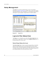
Layout of the Setup View . . . . . . . . . . . . . . . . . . . . . . . . .56
Select Setup (Setup Archives) . . . . . . . . . . . . . . . . . . . 56
Configure Setup (Current Setup) . . . . . . . . . . . . . . . . . 57
Opening a Setup . . . . . . . . . . . . . . . . . . . . . . . . . . . . . . . .57
Creating a New Setup . . . . . . . . . . . . . . . . . . . . . . . . . 58
Creating a Copy for Modification . . . . . . . . . . . . . . . . . 58
Opening an Existing Setup . . . . . . . . . . . . . . . . . . . . . 59
Saving a Setup . . . . . . . . . . . . . . . . . . . . . . . . . . . . . . . . .59
Deleting a Setup . . . . . . . . . . . . . . . . . . . . . . . . . . . . . . . . .60
Exporting a Setup . . . . . . . . . . . . . . . . . . . . . . . . . . . . . . . .60
Importing a Setup . . . . . . . . . . . . . . . . . . . . . . . . . . . . . . . .61
Exporting All Setups . . . . . . . . . . . . . . . . . . . . . . . . . . . . . .61
Importing Multiple Setups . . . . . . . . . . . . . . . . . . . . . . . . . .62
Making Backups . . . . . . . . . . . . . . . . . . . . . . . . . . . . . . . . .62
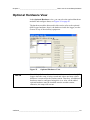
Optional Hardware View . . . . . . . . . . . . . . . . . . . . . . . . . . . .63
Selecting Hardware . . . . . . . . . . . . . . . . . . . . . . . . . . . . . .64
Removing Hardware . . . . . . . . . . . . . . . . . . . . . . . . . . . . .64
Configuring Hardware Modules . . . . . . . . . . . . . . . . . . . . .64
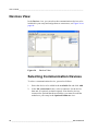
Devices View . . . . . . . . . . . . . . . . . . . . . . . . . . . . . . . . . . . . .66
Selecting Communication Devices . . . . . . . . . . . . . . . . . . .66
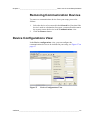
Removing Communication Devices . . . . . . . . . . . . . . . . . .67
Device Configurations View . . . . . . . . . . . . . . . . . . . . . . . . .67
Non-TCP/IP Communication Devices . . . . . . . . . . . . . . . .68
TCP/IP-Based Communication Devices . . . . . . . . . . . . . .68
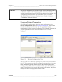
Common Modem Parameters . . . . . . . . . . . . . . . . . . . 69
Communication Interfaces View . . . . . . . . . . . . . . . . . . . . .71
Adding Communication Interfaces . . . . . . . . . . . . . . . . . . .71
IP Services View . . . . . . . . . . . . . . . . . . . . . . . . . . . . . . . . . .72
Selecting IP Services . . . . . . . . . . . . . . . . . . . . . . . . . . . . .73
Removing IP Services . . . . . . . . . . . . . . . . . . . . . . . . . . . .73
Equipment View . . . . . . . . . . . . . . . . . . . . . . . . . . . . . . . . . . .74
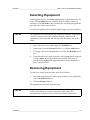
Selecting Equipment . . . . . . . . . . . . . . . . . . . . . . . . . . . . .75
Removing Equipment . . . . . . . . . . . . . . . . . . . . . . . . . . . . .75
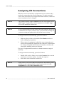
Assigning I/O Connections . . . . . . . . . . . . . . . . . . . . . . . . .76
Re-assigning Connectors . . . . . . . . . . . . . . . . . . . . . . . . . .77
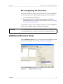
Additional Sensors View . . . . . . . . . . . . . . . . . . . . . . . . . . .77
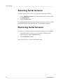
Selecting Serial Sensors . . . . . . . . . . . . . . . . . . . . . . . . . .78
Removing Serial Sensors . . . . . . . . . . . . . . . . . . . . . . . . . .78
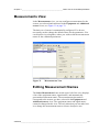
Measurements View . . . . . . . . . . . . . . . . . . . . . . . . . . . . . . .79
Editing Measurement Names . . . . . . . . . . . . . . . . . . . . . . .79
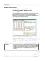
Configuring Measurement Parameters . . . . . . . . . . . . . . .80
2 ____________________________________________________________________M210785EN-E
________________________________________________________________________________
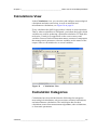
Calculations View . . . . . . . . . . . . . . . . . . . . . . . . . . . . . . . . . 81
Calculation Categories . . . . . . . . . . . . . . . . . . . . . . . . . . . . 81
Meteorological Calculations . . . . . . . . . . . . . . . . . . . . . 82
Unit Conversions . . . . . . . . . . . . . . . . . . . . . . . . . . . . . 82
Arithmetic Operations . . . . . . . . . . . . . . . . . . . . . . . . . 82
Statistical Calculations . . . . . . . . . . . . . . . . . . . . . . . . . 83
Miscellaneous Calculations . . . . . . . . . . . . . . . . . . . . . 84
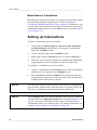
Setting up Calculations . . . . . . . . . . . . . . . . . . . . . . . . . . . 84
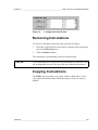
Removing Calculations . . . . . . . . . . . . . . . . . . . . . . . . . . . 85
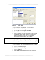
Copying Calculations . . . . . . . . . . . . . . . . . . . . . . . . . . . . . 85
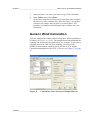
Generic Wind Calculation . . . . . . . . . . . . . . . . . . . . . . . . . 87
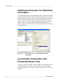
Additional Parameter for Statistical Calculation . . . . . . . . . 88
Accumulator Calculation with Predefined Reset Time . . . . 88
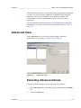
Advanced View . . . . . . . . . . . . . . . . . . . . . . . . . . . . . . . . . . . 89
Selecting Advanced Items . . . . . . . . . . . . . . . . . . . . . . . . . 89
Removing Advanced Items . . . . . . . . . . . . . . . . . . . . . . . . 90
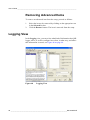
Logging View . . . . . . . . . . . . . . . . . . . . . . . . . . . . . . . . . . . . . 90
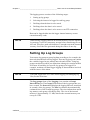
Setting Up Log Groups . . . . . . . . . . . . . . . . . . . . . . . . . . . 91
Deleting Log Groups . . . . . . . . . . . . . . . . . . . . . . . . . . . . . 92
Selecting Log Group Items . . . . . . . . . . . . . . . . . . . . . . . . 92
Removing Log Group Items . . . . . . . . . . . . . . . . . . . . . . . . 93
Sorting Log Group Items . . . . . . . . . . . . . . . . . . . . . . . . . . 93
Selecting Log Item Options . . . . . . . . . . . . . . . . . . . . . . . . 93
Selecting Log Group Options . . . . . . . . . . . . . . . . . . . . . . . 94
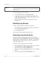
Storing Log Group Data . . . . . . . . . . . . . . . . . . . . . . . . . . . 94
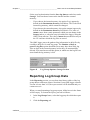
Reporting Log Group Data . . . . . . . . . . . . . . . . . . . . . . . . . 95
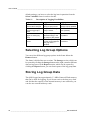
Log Group Report Types . . . . . . . . . . . . . . . . . . . . . . . . . . 96
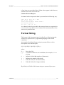
Format String . . . . . . . . . . . . . . . . . . . . . . . . . . . . . . . . . . . 97
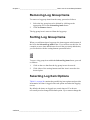
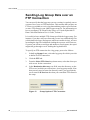
Sending Log Group Data over an FTP Connection . . . . . . 98
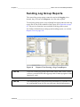
Sending Log Group Reports . . . . . . . . . . . . . . . . . . . . . . . 99
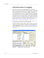
Unit Conversion in Logging . . . . . . . . . . . . . . . . . . . . . . . 100
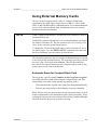
Using External Memory Cards . . . . . . . . . . . . . . . . . . . . . 101
Automatic Erase for Compact Flash Card . . . . . . . . . 101
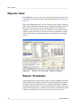
Reports View . . . . . . . . . . . . . . . . . . . . . . . . . . . . . . . . . . . . 102
Report Templates . . . . . . . . . . . . . . . . . . . . . . . . . . . . . . 102
TableForm Report . . . . . . . . . . . . . . . . . . . . . . . . . . . 103
StringForm Report . . . . . . . . . . . . . . . . . . . . . . . . . . . 103
Preformatted Report . . . . . . . . . . . . . . . . . . . . . . . . . 103
BUFR Report . . . . . . . . . . . . . . . . . . . . . . . . . . . . . . . 104
Setting up a Report . . . . . . . . . . . . . . . . . . . . . . . . . . . . . 104
Deleting a Report . . . . . . . . . . . . . . . . . . . . . . . . . . . . . . . 105
Filling out Reports . . . . . . . . . . . . . . . . . . . . . . . . . . . . . . 105
Inserting Text into a Report . . . . . . . . . . . . . . . . . . . . . . . 105
Selecting Variables for a Report . . . . . . . . . . . . . . . . . . . 106
Removing Variables from a Report . . . . . . . . . . . . . . . . . 106
Editing Reports . . . . . . . . . . . . . . . . . . . . . . . . . . . . . . . . 107
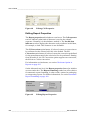
Editing Cell Properties . . . . . . . . . . . . . . . . . . . . . . . . 107
Editing Report Properties. . . . . . . . . . . . . . . . . . . . . . 108
Adding Rows or Columns . . . . . . . . . . . . . . . . . . . . . 109
Removing Rows or Columns . . . . . . . . . . . . . . . . . . . 109
Unit Conversion in Reports . . . . . . . . . . . . . . . . . . . . . . . 109
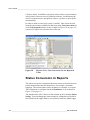
Status Conversion in Reports . . . . . . . . . . . . . . . . . . . . . 110
VAISALA ________________________________________________________________________ 3
User’s Guide ______________________________________________________________________
Adding Preformatted Reports . . . . . . . . . . . . . . . . . . . . . .113
Copying Reports . . . . . . . . . . . . . . . . . . . . . . . . . . . . . . .117
Checksum Option in Reports . . . . . . . . . . . . . . . . . . . . . .119
Binary Report . . . . . . . . . . . . . . . . . . . . . . . . . . . . . . . . . .119
Communications View . . . . . . . . . . . . . . . . . . . . . . . . . . . .120
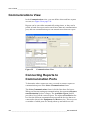
Connecting Reports to Communication Ports . . . . . . . . .120
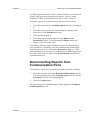
Disconnecting Reports from Communication Ports . . . . .121
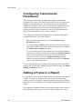
Configuring Transmission Parameters . . . . . . . . . . . . . . .122
Adding a Frame to a Report . . . . . . . . . . . . . . . . . . . . . . .122
Working with a Setup Created in Pre-6.0 Lizard . . . . 123
Working with a Setup Created in Lizard 6.0 or Later . 123
Configuring Polled Report Sending . . . . . . . . . . . . . . . . .124
Alarms View . . . . . . . . . . . . . . . . . . . . . . . . . . . . . . . . . . . . .126
Alarm Types . . . . . . . . . . . . . . . . . . . . . . . . . . . . . . . . . . .127
Print Report Alarms . . . . . . . . . . . . . . . . . . . . . . . . . . 127
Save Log Group Alarms. . . . . . . . . . . . . . . . . . . . . . . 127
Set Excitation Output Alarms . . . . . . . . . . . . . . . . . . . 127
Set Digital Output Alarms. . . . . . . . . . . . . . . . . . . . . . 128
Generic Alarms . . . . . . . . . . . . . . . . . . . . . . . . . . . . . 128
Update Timer Interval. . . . . . . . . . . . . . . . . . . . . . . . . 128
Creating Alarms . . . . . . . . . . . . . . . . . . . . . . . . . . . . . . . .128
Removing Alarms . . . . . . . . . . . . . . . . . . . . . . . . . . . . . . .129
Configuring Alarms . . . . . . . . . . . . . . . . . . . . . . . . . . . . . .129
Timers View . . . . . . . . . . . . . . . . . . . . . . . . . . . . . . . . . . . . .131
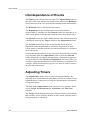
Interdependence of Events . . . . . . . . . . . . . . . . . . . . . . .132
Adjusting Timers . . . . . . . . . . . . . . . . . . . . . . . . . . . . . . .132
Advanced Use of Timers . . . . . . . . . . . . . . . . . . . . . . . . .134
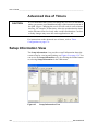
Setup Information View . . . . . . . . . . . . . . . . . . . . . . . . . . .134
Generating and Uploading a Setup . . . . . . . . . . . . . . . . . .138
Generating a Setup for QML Logger . . . . . . . . . . . . . . . .138
Generating a Setup with or without Script Comments . . .138
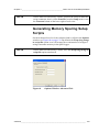
Generating Memory Sparing Setup Scripts . . . . . . . . . . .139
Tracing Errors in Lizard . . . . . . . . . . . . . . . . . . . . . . . . . . .140
CHAPTER 5
ADVANCED USE OF LIZARD SETUP SOFTWARE . . . . . . . . . . . . . . . .141
Changing the User Level to Advanced . . . . . . . . . . . . . . .141
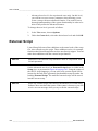
External Script . . . . . . . . . . . . . . . . . . . . . . . . . . . . . . . . . . .142
Static Parameters . . . . . . . . . . . . . . . . . . . . . . . . . . . . . . . .144
Creating Static Parameters . . . . . . . . . . . . . . . . . . . . . . .144
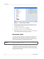
Changing Values of Static Parameters . . . . . . . . . . . . . .145
Parameter Sets . . . . . . . . . . . . . . . . . . . . . . . . . . . . . . . .146
Parameter Set Management In Lizard . . . . . . . . . . . . 147
Daylight Saving . . . . . . . . . . . . . . . . . . . . . . . . . . . . . . . . . .149
Time Receiver . . . . . . . . . . . . . . . . . . . . . . . . . . . . . . . . . . .152
Setting System Time . . . . . . . . . . . . . . . . . . . . . . . . . . . .152
Reading System Time . . . . . . . . . . . . . . . . . . . . . . . . . . .152
Log Sender . . . . . . . . . . . . . . . . . . . . . . . . . . . . . . . . . . . . .153
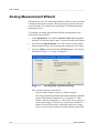
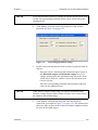
Analog Measurement Wizard . . . . . . . . . . . . . . . . . . . . . . .154
4 ____________________________________________________________________M210785EN-E
________________________________________________________________________________
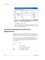
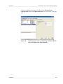
Combined Wind Speed and Direction Measurement . . . . 156
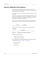
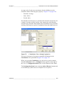
Generic Statistical Calculations . . . . . . . . . . . . . . . . . . . . 158
Additional Calculation Options . . . . . . . . . . . . . . . . . . . . . 160
Setting Unit for Generic Sensors . . . . . . . . . . . . . . . . . . . 161
Setting Unit and Conversion for Manual Sensors . . . . . . 162
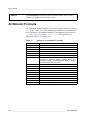
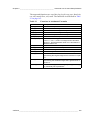
Arithmetic Formula . . . . . . . . . . . . . . . . . . . . . . . . . . . . . . . 164
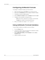
Configuring Arithmetic Formula . . . . . . . . . . . . . . . . . . . . 166
Using Arithmetic Formula Variables . . . . . . . . . . . . . . . . . 166
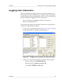
Logging User Interaction . . . . . . . . . . . . . . . . . . . . . . . . . . 167
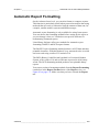
Automatic Report Formatting . . . . . . . . . . . . . . . . . . . . . . 169
User-Definable Field Formatting . . . . . . . . . . . . . . . . . . . . 174
Timer Configuration . . . . . . . . . . . . . . . . . . . . . . . . . . . . . . 176
Principles of Timed Operation . . . . . . . . . . . . . . . . . . . . . 176
Timer Operation and Parameters . . . . . . . . . . . . . . . 176
Modifying Timers . . . . . . . . . . . . . . . . . . . . . . . . . . . . . . . 179
Automatic Sequencing Principles . . . . . . . . . . . . . . . . . . 181
Changing Timer Intervals . . . . . . . . . . . . . . . . . . . . . . . . . 182
Threshold-Dependent Timer Intervals . . . . . . . . . . . . . . . 182
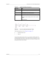
Example of Timer Intervals . . . . . . . . . . . . . . . . . . . . 184
Interval Update Rules . . . . . . . . . . . . . . . . . . . . . . . . 185
Changing Synchronization Times of Single Events . . . . . 186
Changing Synchronization Times of Multiple Events . . . . 186
Using Static Parameters with Timers . . . . . . . . . . . . . . . . 187
Resetting Sum Calculation Using Alarms . . . . . . . . . . . . 189
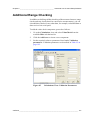
Additional Range Checking . . . . . . . . . . . . . . . . . . . . . . . . 191
Configuring Calculations and Reports . . . . . . . . . . . . . . . 195
Accumulator with Predefined Reset Time . . . . . . . . . . . . 195
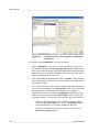
Configuring Accumulator . . . . . . . . . . . . . . . . . . . . . . 195
Resetting Accumulator Manually . . . . . . . . . . . . . . . . 197
Using the Accumulator Variable in Reports . . . . . . . . 199
Power Control Option . . . . . . . . . . . . . . . . . . . . . . . . . . . . 199
Configuring Power Control Option . . . . . . . . . . . . . . . 200
Timer Option . . . . . . . . . . . . . . . . . . . . . . . . . . . . . . . . . . 201
Configuring Timer Option. . . . . . . . . . . . . . . . . . . . . . 201
Enhanced Time Snapshot . . . . . . . . . . . . . . . . . . . . . . . . 203
Checksum Option in Reports . . . . . . . . . . . . . . . . . . . . . . 203
Creating Checksum Report . . . . . . . . . . . . . . . . . . . . 204
Binary Report . . . . . . . . . . . . . . . . . . . . . . . . . . . . . . . . . . 207
Creating Binary Report . . . . . . . . . . . . . . . . . . . . . . . 207
Additional Features . . . . . . . . . . . . . . . . . . . . . . . . . . . . . . . 212
Floating Point Numbers in Static Parameters . . . . . . . . . 212
Enhanced Generic Frequency Measurement . . . . . . . . . 212
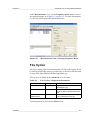
File Cycler . . . . . . . . . . . . . . . . . . . . . . . . . . . . . . . . . . . . 213
VAISALA ________________________________________________________________________ 5
User’s Guide ______________________________________________________________________
6 ____________________________________________________________________M210785EN-E
________________________________________________________________________________
List of Figures
Figure 1
Figure 2
Figure 3
Figure 4
Figure 5
Figure 6
Figure 7
Figure 8
Figure 9
Figure 10
Figure 11
Figure 12
Figure 13
Figure 14
Figure 15
Figure 16
Figure 17
Figure 18
Figure 19
Figure 20
Figure 21
Figure 22
Figure 23
Figure 24
Figure 25
Figure 26
Figure 27
Figure 28
Figure 29
Figure 30
Figure 31
Figure 32
Figure 33
Figure 34
Figure 35
Figure 36
Figure 37
Figure 38
Figure 39
Figure 40
Figure 41
Figure 42
Figure 43
Figure 44
Figure 45
Welcome Window . . . . . . . . . . . . . . . . . . . . . . . . . . . . . . . . . . 26
License Agreement Window . . . . . . . . . . . . . . . . . . . . . . . . . . 27
Customer Information Window. . . . . . . . . . . . . . . . . . . . . . . . . 27
Setup Type Window . . . . . . . . . . . . . . . . . . . . . . . . . . . . . . . . . 28
Ready to Install Window. . . . . . . . . . . . . . . . . . . . . . . . . . . . . . 29
Installing MAWS Lizard Window . . . . . . . . . . . . . . . . . . . . . . . 29
Installation Completed Window . . . . . . . . . . . . . . . . . . . . . . . . 30
Example View of Wizard Tool . . . . . . . . . . . . . . . . . . . . . . . . . 32
Example of Wizard Setup. . . . . . . . . . . . . . . . . . . . . . . . . . . . . 33
Disabling or Enabling Wizard Tool . . . . . . . . . . . . . . . . . . . . . . 33
Setup View . . . . . . . . . . . . . . . . . . . . . . . . . . . . . . . . . . . . . . . . 34
New Setup Window . . . . . . . . . . . . . . . . . . . . . . . . . . . . . . . . . 35
Selecting Wizard from the View Menu . . . . . . . . . . . . . . . . . . . 36
Selecting Sensors . . . . . . . . . . . . . . . . . . . . . . . . . . . . . . . . . . 37
Selecting Meteorological Calculations . . . . . . . . . . . . . . . . . . . 38
Data Missing Message. . . . . . . . . . . . . . . . . . . . . . . . . . . . . . . 38
Selecting Statistical Calculations . . . . . . . . . . . . . . . . . . . . . . . 39
Selecting Variables for One-Hour Logging. . . . . . . . . . . . . . . . 40
Selecting Reports. . . . . . . . . . . . . . . . . . . . . . . . . . . . . . . . . . . 41
Selecting Report Destination . . . . . . . . . . . . . . . . . . . . . . . . . . 42
Completing the Setup . . . . . . . . . . . . . . . . . . . . . . . . . . . . . . . 43
Example View of User Interface. . . . . . . . . . . . . . . . . . . . . . . . 50
Lizard Setup Software Toolbar. . . . . . . . . . . . . . . . . . . . . . . . . 52
Setup View . . . . . . . . . . . . . . . . . . . . . . . . . . . . . . . . . . . . . . . . 56
Optional Hardware View . . . . . . . . . . . . . . . . . . . . . . . . . . . . . 63
Devices View . . . . . . . . . . . . . . . . . . . . . . . . . . . . . . . . . . . . . . 66
Device Configurations View . . . . . . . . . . . . . . . . . . . . . . . . . . . 67
Modem Configuration View . . . . . . . . . . . . . . . . . . . . . . . . . . . 69
Communication Interfaces View. . . . . . . . . . . . . . . . . . . . . . . . 71
IP Services View . . . . . . . . . . . . . . . . . . . . . . . . . . . . . . . . . . . 72
Equipment View . . . . . . . . . . . . . . . . . . . . . . . . . . . . . . . . . . . . 74
Additional Sensors View . . . . . . . . . . . . . . . . . . . . . . . . . . . . . 77
Measurements View. . . . . . . . . . . . . . . . . . . . . . . . . . . . . . . . . 79
Calculations View. . . . . . . . . . . . . . . . . . . . . . . . . . . . . . . . . . . 81
Configuration Item Frame . . . . . . . . . . . . . . . . . . . . . . . . . . . . 85
Utility Menu . . . . . . . . . . . . . . . . . . . . . . . . . . . . . . . . . . . . . . . 86
Calculations View: Selection of Sample Interval . . . . . . . . . . . 87
Calculations View: Configuring Statistical Calculation . . . . . . . 88
Advanced View . . . . . . . . . . . . . . . . . . . . . . . . . . . . . . . . . . . . 89
Logging View . . . . . . . . . . . . . . . . . . . . . . . . . . . . . . . . . . . . . . 90
Log Group Options: Storage Section . . . . . . . . . . . . . . . . . . . . 95
Group Options: Report Section . . . . . . . . . . . . . . . . . . . . . . . . 96
Group Options: FTP Connection . . . . . . . . . . . . . . . . . . . . . . . 98
Reports View Showing a Log Group Report . . . . . . . . . . . . . . 99
Logging View: Unit Conversion . . . . . . . . . . . . . . . . . . . . . . . 100
VAISALA ________________________________________________________________________ 7
User’s Guide ______________________________________________________________________
Figure 46
Figure 47
Figure 48
Figure 49
Figure 50
Figure 51
Figure 52
Figure 53
Figure 54
Figure 55
Figure 56
Figure 57
Figure 58
Figure 59
Figure 60
Figure 61
Figure 62
Figure 63
Figure 64
Figure 65
Figure 66
Figure 67
Figure 68
Figure 69
Figure 70
Figure 71
Figure 72
Figure 73
Figure 74
Figure 75
Figure 76
Figure 77
Figure 78
Figure 79
Figure 80
Figure 81
Figure 82
Figure 83
Figure 84
Figure 85
Figure 86
Figure 87
Figure 88
Figure 89
Figure 90
Figure 91
Figure 92
Figure 93
Figure 94
Figure 95
Figure 96
Reports View Showing a TableForm Report . . . . . . . . . . . . .102
Reports View Showing a StringForm Report . . . . . . . . . . . . .104
Editing Cell Properties . . . . . . . . . . . . . . . . . . . . . . . . . . . . . .108
Editing Report Properties . . . . . . . . . . . . . . . . . . . . . . . . . . . .108
Reports View: Unit Conversion for the Reported Value . . . . .110
Calculations View: Configuring Status Strings (1/2). . . . . . . .111
Calculations View: Configuring Status Strings (2/2). . . . . . . .112
Reports View: Selecting status_str to a Report . . . . . . . . . . .113
Reports View: Available Templates . . . . . . . . . . . . . . . . . . . .114
Preformatted Report Template with Tags . . . . . . . . . . . . . . .115
Preformatted Report with Variables . . . . . . . . . . . . . . . . . . . .116
Automatic Report Formatting Message . . . . . . . . . . . . . . . . .117
Utility Menu . . . . . . . . . . . . . . . . . . . . . . . . . . . . . . . . . . . . . .117
Communications View . . . . . . . . . . . . . . . . . . . . . . . . . . . . . .120
Communications View with Configuration for a Device . . . . .125
Alarms View . . . . . . . . . . . . . . . . . . . . . . . . . . . . . . . . . . . . . .126
Timers View . . . . . . . . . . . . . . . . . . . . . . . . . . . . . . . . . . . . . .131
Setup Information View . . . . . . . . . . . . . . . . . . . . . . . . . . . . .134
Options Window: Advanced Tab . . . . . . . . . . . . . . . . . . . . . .139
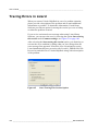
Start Tracing This Session Option . . . . . . . . . . . . . . . . . . . . .140
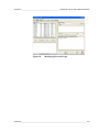
Modifying External Script . . . . . . . . . . . . . . . . . . . . . . . . . . . .143
Setup View: Static Parameters Tab . . . . . . . . . . . . . . . . . . . .144
Static Parameters Window . . . . . . . . . . . . . . . . . . . . . . . . . . .146
Parameter Sets Window. . . . . . . . . . . . . . . . . . . . . . . . . . . . .147
Daylight Saving Time Setup . . . . . . . . . . . . . . . . . . . . . . . . . .149
User Defined Daylight Saving . . . . . . . . . . . . . . . . . . . . . . . .150
Activating Years to Configure Window . . . . . . . . . . . . . . . . . .151
Selecting Input Type and Powering . . . . . . . . . . . . . . . . . . . .154
Converting Parameter Setup . . . . . . . . . . . . . . . . . . . . . . . . .155
Electrical Connection View. . . . . . . . . . . . . . . . . . . . . . . . . . .156
Measurements View: Configuring Combined Wind Speed
and Direction Measurement . . . . . . . . . . . . . . . . . . . . . . . . . .157
Example of Data Table and Queries . . . . . . . . . . . . . . . . . . .158
Calculations View: Setting Up Queries. . . . . . . . . . . . . . . . . .159
Additional Calculation Options . . . . . . . . . . . . . . . . . . . . . . . .161
Measurements View: Configuring Frequency Measurement .162
Measurements View: Configuring Manual Sensor . . . . . . . . .163
Logging View: Defining User Interaction Log . . . . . . . . . . . . .167
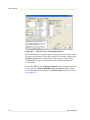
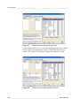
Reports View: Formatting Reports . . . . . . . . . . . . . . . . . . . . .170
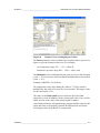
Reports View: Scaling Report Values . . . . . . . . . . . . . . . . . .171
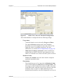
Advanced User Level Cell Properties Tab . . . . . . . . . . . . . . .174
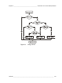
Intervals and Synchronization Times . . . . . . . . . . . . . . . . . . .177
Timers View on Normal User Level . . . . . . . . . . . . . . . . . . . .180
Timers View on Advanced User Level . . . . . . . . . . . . . . . . . .180
Alarms View: Interval Threshold Configuration . . . . . . . . . . .183
Threshold Definitions . . . . . . . . . . . . . . . . . . . . . . . . . . . . . . .185
Setup View: Static Parameters Tab . . . . . . . . . . . . . . . . . . . .187
Edit Timer Window . . . . . . . . . . . . . . . . . . . . . . . . . . . . . . . . .188
Alarms View: Monitored Value and Target. . . . . . . . . . . . . . .189
Alarms View: Condition for Generic Alarm . . . . . . . . . . . . . . .190
Calculations View: Validation Parameters . . . . . . . . . . . . . . .191
Range Check . . . . . . . . . . . . . . . . . . . . . . . . . . . . . . . . . . . . .193
8 ____________________________________________________________________M210785EN-E
________________________________________________________________________________
Figure 97
Figure 98
Figure 99
Figure 100
Figure 101
Figure 102
Figure 103
Figure 104
Figure 105
Figure 106
Figure 107
Figure 108
Figure 109
Figure 110
Figure 111
Step Check . . . . . . . . . . . . . . . . . . . . . . . . . . . . . . . . . . . . . . 194
Calculations View: Selecting the Accumulator Component . . 196
Select Time: Selecting Accumulator Resetting Schedule . . . 197
Static Parameters Window: Entering Accumulator Reset
Value Manually . . . . . . . . . . . . . . . . . . . . . . . . . . . . . . . . . . . 198
Devices View: Connecting Power Control . . . . . . . . . . . . . . . 200
Device Configurations View: Configuring Power Control
Option . . . . . . . . . . . . . . . . . . . . . . . . . . . . . . . . . . . . . . . . . . 201
Calculations View: Configuring Timer Option. . . . . . . . . . . . . 202
Reports View: UNIX Time Option under Time Snap . . . . . . . 203
Reports View: Configuring New Checksum Report . . . . . . . . 204
Reports View: Adding CRC . . . . . . . . . . . . . . . . . . . . . . . . . . 205
Checksum Settings Window . . . . . . . . . . . . . . . . . . . . . . . . . 206
Reports View: Selecting Binary Report Form. . . . . . . . . . . . . 208
Reports View: Binary Report Formatting Frame (1/2) . . . . . . 208
Reports View: Binary Report Formatting Frame (2/2) . . . . . . 211
Measurements View: Selecting Frequency Mode . . . . . . . . . 213
VAISALA ________________________________________________________________________ 9
User’s Guide ______________________________________________________________________
10 ___________________________________________________________________M210785EN-E
________________________________________________________________________________
List of Tables
Table 1
Table 2
Table 3
Table 4
Table 5
Table 6
Table 7
Table 8
Table 9
Table 10
Table 11
Table 12
Table 13
Table 14
Table 15
Table 16
Table 17
Table 18
Table 19
Table 20
Table 21
Table 22
Table 23
Table 24
Table 25
Table 26
Structure of the DCP Manual Set. . . . . . . . . . . . . . . . . . . . . . . . . 14
Manual Versions . . . . . . . . . . . . . . . . . . . . . . . . . . . . . . . . . . . . . 15
Related Manuals . . . . . . . . . . . . . . . . . . . . . . . . . . . . . . . . . . . . . 15
Minimum System Requirements . . . . . . . . . . . . . . . . . . . . . . . . . 25
Wizard Calculations Intervals. . . . . . . . . . . . . . . . . . . . . . . . . . . . 45
TCP/IP Communication Devices in Lizard . . . . . . . . . . . . . . . . . . 68
Modem Control Parameters . . . . . . . . . . . . . . . . . . . . . . . . . . . . . 70
TCP/IP-Based Services . . . . . . . . . . . . . . . . . . . . . . . . . . . . . . . . 73
Available Statistical Functions . . . . . . . . . . . . . . . . . . . . . . . . . . . 83
Timestamps for Statistical Calculations . . . . . . . . . . . . . . . . . . . . 83
Description of Logging Possibilities . . . . . . . . . . . . . . . . . . . . . . . 94
Report Templates . . . . . . . . . . . . . . . . . . . . . . . . . . . . . . . . . . . . 103
Fields under Status Strings . . . . . . . . . . . . . . . . . . . . . . . . . . . . . 111
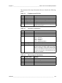
Equipment and I/O List . . . . . . . . . . . . . . . . . . . . . . . . . . . . . . . . 135
Statistical Calculations . . . . . . . . . . . . . . . . . . . . . . . . . . . . . . . . . 135
Meteorological Calculations . . . . . . . . . . . . . . . . . . . . . . . . . . . . . 135
Logged Data . . . . . . . . . . . . . . . . . . . . . . . . . . . . . . . . . . . . . . . . 136
Reported Data . . . . . . . . . . . . . . . . . . . . . . . . . . . . . . . . . . . . . . . 136
Report Communications. . . . . . . . . . . . . . . . . . . . . . . . . . . . . . . . 136
Alarms . . . . . . . . . . . . . . . . . . . . . . . . . . . . . . . . . . . . . . . . . . . . . 137
Timed Events . . . . . . . . . . . . . . . . . . . . . . . . . . . . . . . . . . . . . . . . 137
Operators in Arithmetic Formulas . . . . . . . . . . . . . . . . . . . . . . . . 164
Functions in Arithmetic Formulas. . . . . . . . . . . . . . . . . . . . . . . . . 165
Application Timer Parameters . . . . . . . . . . . . . . . . . . . . . . . . . . . 177
Validation Parameters . . . . . . . . . . . . . . . . . . . . . . . . . . . . . . . . . 192
File Cycler Configuration Parameters . . . . . . . . . . . . . . . . . . . . . 213
VAISALA _______________________________________________________________________ 11
User’s Guide ______________________________________________________________________
12 ___________________________________________________________________M210785EN-E
Chapter 1 ________________________________________________________ General Information
CHAPTER 1
GENERAL INFORMATION
This chapter provides general notes for the product(s) and this manual.
About This Manual
This manual contains information on the basic use of Lizard Setup
Software using the Wizard tool and also more detailed and advanced
information on creating and modifying setups. Applicable for data
logger QML201C and Lizard Setup Software versions 8.00 and AWS
Client terminal software version 7.00.
VAISALA _______________________________________________________________________ 13
User’s Guide ______________________________________________________________________
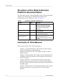
Structure of the Data Collection
Platform Documentation
The information in the Vaisala HydroMet™ Data Collection Platform
manual set is divided between the different manuals in the
documentation set as outlined in Table 1 on page 14.
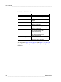
Table 1
Manual
Structure of the DCP Manual Set
Code
Content
User’s Guide, Volume 1 M210784EN Overview of the data collection
platform, the QML logger, and
related accessories. Operating
instructions for AWS Client
software.
User’s Guide, Volume 2 M210785EN Operating instructions for Lizard
Setup Software.
User’s Guide, Volume 3 M210933EN Telemetry and sensor configuration
in Lizard Setup Software.
Installation Manual
M210786EN Installation information on the Data
(Field Equipment)
Collection Platform with
meteorological and/or hydrological
sensors.
Contents of This Manual
This manual consists of the following chapters:
-
Chapter 1, General Information: This chapter provides general
notes for the product(s) and this manual.
-
Chapter 2, Product Overview: This chapter introduces Lizard
Setup Software.
-
Chapter 3, Getting Started: This chapter provides information on
installing Lizard Setup Software and on using the Wizard tool to
create new setups.
-
Chapter 4, Basic Use of Lizard Setup Software: This chapter
provides instructions for the basic use of Lizard Setup Software
which is used to modify the software parameters and operation of
the QML logger.
-
Chapter 5, Advanced Use of Lizard Setup Software: This chapter
provides information on the advanced use of Lizard Setup
Software.
14 ___________________________________________________________________M210785EN-E
Chapter 1 ________________________________________________________ General Information
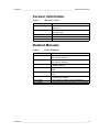
Version Information
Table 2
Manual Versions
Manual Code
Description
M210785EN-E
This version. For MAWS system release 8.00 and
QML201C.
Previous version. For MAWS system release 7.00
and QML201B.
Previous version.
Previous version.
First version of this manual.
M210785EN-D
M210785EN-C
M210785EN-B
M210785EN-A
Related Manuals
Table 3
Related Manuals
Manual Code
Manual Name
M210784EN
Vaisala HydroMet™ Data Collection Platform
User’s Guide, Volume 1
Vaisala HydroMet™ Data Collection Platform
User’s Guide, Volume 3
Vaisala HydroMet™ Data Collection Platform
Installation Manual
Automatic Weather Station MAWS101 User's
Guide
Automatic Weather Station MAWS201 User's
Guide
Real-time Display Software YourVIEW 2000
UVY2000 User’s Guide
Voice Option for MAWS Technical Reference
Configuring BUFR Reports MAWS Technical Note
M210933EN
M210786EN
M210629EN
M210630EN
M210681EN
M210743EN
M211022EN
VAISALA _______________________________________________________________________ 15
User’s Guide ______________________________________________________________________
Documentation Conventions
Throughout this manual, important safety considerations are
highlighted as follows:
WARNING
Warning alerts you to a serious hazard. If you do not read and follow
instructions very carefully at this point, there is a risk of injury or even
death.
CAUTION
Caution warns you of a potential hazard. If you do not read and follow
instructions carefully at this point, the product could be damaged or
important data could be lost.
NOTE
Note highlights important information on using the product.
16 ___________________________________________________________________M210785EN-E
Chapter 1 ________________________________________________________ General Information
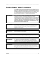
Product-Related Safety Precautions
The product has been tested for safety and approved as shipped from the
factory. The following safety precautions are not related to any specific
procedures and therefore do not appear elsewhere in this manual. They
are recommended precautions that personnel must understand and
apply during different phases of operation and maintenance.
WARNING
Keep away from live circuits. Operating personnel must observe safety
regulations at all times. Component replacement or internal
adjustments must be made by qualified maintenance personnel. Do not
replace components with the power cable connected. Under certain
conditions, dangerous voltages may exist for some time even with the
power cable disconnected. To avoid injuries, disconnect power and
discharge circuits before touching them.
WARNING
Do not service alone. Under no circumstances should any person reach
into parts and assemblies that are mains powered and alive, for the
purpose of servicing, except in the presence of someone who is
capable of rendering aid.
WARNING
Personnel working with or near high voltages should be familiar with
modern methods of resuscitation.
WARNING
Do not service a live system outdoors. Do not open units outdoors
when the enclosure used contains line voltage levels.
WARNING
Do not operate in an explosive atmosphere, for example, when
flammable gases or fumes are present. Operation of any electrical
instrument in such an environment constitutes a definite safety hazard.
WARNING
Do not substitute parts or modify the instrument. Because of the
danger of introducing additional hazards, do not install unsuitable
parts in the instrument. Contact Vaisala or its authorized representative
for repairs to ensure that safety features are maintained.
VAISALA _______________________________________________________________________ 17
User’s Guide ______________________________________________________________________
WARNING
Use only batteries of the same type as originally installed on the
system.
CAUTION
Do not make changes to the wiring. Incorrect wiring can damage the
device and prevent it from operating correctly.
CAUTION
Risk of damage to the equipment if the battery is replaced with an
incorrect type.
ESD Protection
Electrostatic Discharge (ESD) can cause immediate or latent damage to
electronic circuits. Vaisala products are adequately protected against
ESD for their intended use. However, it is possible to damage the
product by delivering electrostatic discharges when touching,
removing, or inserting any objects inside the equipment housing.
To make sure you are not delivering high static voltages yourself:
-
Handle ESD sensitive components on a properly grounded and
protected ESD workbench. When this is not possible, ground
yourself with a wrist strap and a resistive connection cord to the
equipment chassis before touching the boards. When neither of the
above is possible, at least touch a conductive part of the equipment
chassis with your other hand before touching the boards.
-
Always hold the boards by the edges and avoid touching the
component contacts.
18 ___________________________________________________________________M210785EN-E
Chapter 1 ________________________________________________________ General Information
Recycling
Recycle all applicable material.
Dispose of batteries and the unit according to statutory regulations.
Do not dispose of with regular household refuse.
Regulatory Compliances
The Vaisala HydroMet™ Data Collection Platform complies with the
following EU directives:
-
Low Voltage Directive (2006/95/EC)
-
EMC-Directive (2004/108/EC)
Trademarks
Vaisala HydroMet™ Data Collection Platform is a trademark of
Vaisala Oyj.
Windows® is a registered trademark of Microsoft Corporation in the
United States and/or other countries.
License Agreement
All rights to any software are held by Vaisala or third parties. The
customer is allowed to use the software only to the extent that is
provided by the applicable supply contract or Software License
Agreement.
VAISALA _______________________________________________________________________ 19
User’s Guide ______________________________________________________________________
Redistribution License Agreement
The QML logger software uses the TCP/IP stack produced by the "lwIP
Lightweight TCP/IP stack" -project with the following copyright and
license:
Copyright © 2001, 2002 Swedish Institute of Computer Science. All
rights reserved.
Redistribution and use in source and binary forms, with or without
modification, are permitted provided that the following conditions are
met:
1.
Redistributions of source code must retain the above copyright
notice, this list of conditions and the following disclaimer.
2.
Redistributions in binary form must reproduce the above copyright
notice, this list of conditions and the following disclaimer in the
documentation and/or other materials provided with the
distribution.
3.
The name of the author may not be used to endorse or promote
products derived from this software without specific prior written
permission.
THIS SOFTWARE IS PROVIDED BY THE AUTHOR "AS IS" AND
ANY EXPRESS OR IMPLIED WARRANTIES, INCLUDING, BUT
NOT LIMITED TO, THE IMPLIED WARRANTIES OF
MERCHANTABILITY AND FITNESS FOR A PARTICULAR
PURPOSE ARE DISCLAIMED. IN NO EVENT SHALL THE
AUTHOR BE LIABLE FOR ANY DIRECT, INDIRECT,
INCIDENTAL, SPECIAL, EXEMPLARY, OR CONSEQUENTIAL
DAMAGES (INCLUDING, BUT NOT LIMITED TO,
PROCUREMENT OF SUBSTITUTE GOODS OR SERVICES; LOSS
OF USE, DATA, OR PROFITS; OR BUSINESS INTERRUPTION)
HOWEVER CAUSED AND ON ANY THEORY OF LIABILITY,
WHETHER IN CONTRACT, STRICT LIABILITY, OR TORT
(INCLUDING NEGLIGENCE OR OTHERWISE) ARISING IN ANY
WAY OUT OF THE USE OF THIS SOFTWARE, EVEN IF
ADVISED OF THE POSSIBILITY OF SUCH DAMAGE.
20 ___________________________________________________________________M210785EN-E
Chapter 1 ________________________________________________________ General Information
Warranty
For certain products Vaisala normally gives a limited one-year
warranty. Please observe that any such warranty may not be valid in
case of damage due to normal wear and tear, exceptional operating
conditions, negligent handling or installation, or unauthorized
modifications. Please see the applicable supply contract or Conditions
of Sale for details of the warranty for each product.
VAISALA _______________________________________________________________________ 21
User’s Guide ______________________________________________________________________
22 ___________________________________________________________________M210785EN-E
Chapter 2 __________________________________________________________ Product Overview
CHAPTER 2
PRODUCT OVERVIEW
This chapter introduces Lizard Setup Software.
Lizard Setup Software
With Lizard Setup Software, you can easily create or modify a setup file
that informs the QML logger how to operate.
Creating a setup with Lizard Setup Software consists of three stages.
First, you define an assembly for the weather station. Then you define
the necessary measurements and the calculations derived from them.
Finally, you define the log groups and reports from the measurement
results along with communication settings for transmitting data to and
from the QML logger.
The setup file on your PC is finally generated, in other words, converted
into a format that the QML logger understands and then transferred into
the logger and taken into use.
You can store all settings in the Lizard setup library where they are
easily available for modifications or for creating a new setup based on
an existing one. Also, you can use the import/export function to add new
setup files to the library or to send the existing ones, for example, to
Vaisala HelpDesk in case of a problem situation.
VAISALA _______________________________________________________________________ 23
User’s Guide ______________________________________________________________________
24 ___________________________________________________________________M210785EN-E
Chapter 3 ____________________________________________________________ Getting Started
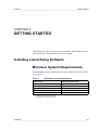
CHAPTER 3
GETTING STARTED
This chapter provides information on installing Lizard Setup Software
and on using the Wizard tool to create new setups.
Installing Lizard Setup Software
Minimum System Requirements
The minimum system requirements for this product are listed in Table
4 on page 25.
Table 4
Minimum System Requirements
Component
Minimum Requirement
PC
Operating System
500 MHz
Memory
Hard Disk Space
Drives
Windows® XP1 or Windows® 20002
256 MB RAM
100 MB
CD-ROM Drive
1. With Service Pack 1 or later
2. With Service Pack 4 or later
VAISALA _______________________________________________________________________ 25
User’s Guide ______________________________________________________________________
Installing Lizard
NOTE
You should perform all installation procedures logged in as an
administrator.
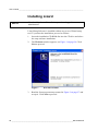
Lizard Setup Software is installed with an easy-to-use Wizard setup
tool. To perform the installation, proceed as follows:
1.
Insert the installation CD-ROM disc into the CD drive and select
the setup software installation.
2.
The Welcome window appears; see Figure 1 on page 26. Click
Next to proceed.
Figure 1
1004-046
3.
Welcome Window
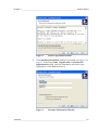
Read the license agreement presented in Figure 2 on page 27 and
accept it. Click Next to proceed.
26 ___________________________________________________________________M210785EN-E
Chapter 3 ____________________________________________________________ Getting Started
Figure 2
1004-047
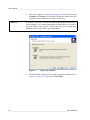
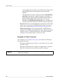
4.
License Agreement Window
The Customer Information window is presented; see Figure 3 on
page 27. In the User Name, Organization, and Install this
application for fields, enter the information relevant to your
organization. Click Next to proceed.
Figure 3
1004-048
Customer Information Window
VAISALA _______________________________________________________________________ 27
User’s Guide ______________________________________________________________________
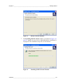
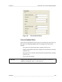
5.
NOTE
Select the setup type; see Figure 4 on page 28. You can either select
Complete or Custom. If you want to change the folder where the
program is to be installed, select the custom setup.
If you have a previous version of Lizard Setup Software installed on
your computer, it is recommended that you install the new version in
the same folder as the previous version. This way, your existing setup
database can be used with the new installation.
Figure 4
1004-049
6.
Setup Type Window
The installation program is now ready to begin the installation; see
Figure 5 on page 29. To proceed, click Install.
28 ___________________________________________________________________M210785EN-E
Chapter 3 ____________________________________________________________ Getting Started
Figure 5
1004-050
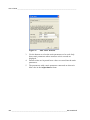
7.
Ready to Install Window
The Installing MAWS Lizard window, presented in Figure 6 on
page 29, appears on your screen, indicating that the installation is
in progress. The installation may take several minutes.
Figure 6
1004-051
Installing MAWS Lizard Window
VAISALA _______________________________________________________________________ 29
User’s Guide ______________________________________________________________________
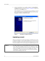
8.
After the installation is successfully completed, the Installation
Completed window, presented in Figure 7 on page 30, appears on
your screen. Click Finish to exit.
Upon installation, a Lizard icon appears on your desktop. You can
also start the program by clicking the Start button and selecting
Programs, Vaisala, and MAWS Lizard.
Figure 7
1004-052
Installation Completed Window
Updating Lizard
When you already have Lizard Setup Software installed and you want
to update the software version, simply install the new version on top of
the old one. Install the new Lizard version by running the setup.exe file
from the installation CD. Your old setups are automatically preserved.
NOTE
If Lizard versions 5.01 or 5.02 are installed on your system, you should
remove them after installing Lizard version 7.00. Otherwise, Lizard
version 7.00 will not work correctly. Do not remove the older version
before first installing 7.00: if you do, you will lose your existing
configurations. Versions other than 5.01 and 5.02 do not need to be
removed after installing Lizard 7.00.
30 ___________________________________________________________________M210785EN-E
Chapter 3 ____________________________________________________________ Getting Started
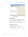
Wizard Tool
NOTE
Due to the limitations of the sensor set available in the Wizard tool,
you may want to use the Lizard setup to create setups. Refer to Chapter
4, Basic Use of Lizard Setup Software, on page 49 for instructions.
The Wizard tool makes the initial creation of setups easier, in other
words, it helps you create basic setups which can be further modified
with Lizard software. Once you have modified the setups with Lizard
software, however, you can no longer open them with the Wizard tool.
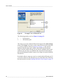
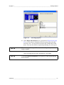
An example view of the Wizard tool is presented in Figure 8 on page 32.
The basic Wizard view includes two important components: the
selection box and the information pane. The basic logic of the Wizard
tool is similar to that of Lizard Setup Software. You create a setup by
going through all the Wizard views. This includes making the necessary
selections in the selection box and moving on to the next view. For more
detailed information on creating setups with the Wizard tool, see section
Creating a Setup with Wizard on page 34.
The basic Wizard view also includes several buttons that are located on
the lower right. You can navigate between the views with the Next and
Back buttons. If you wish to exit the Wizard tool without saving the
setup, click Abort. In the last view you can complete the setup by
clicking Finish. Most Wizard views also include a Clear All button
which you can use for clearing the selections made.
As in Lizard software, there is an information pane on the lower left of
each Wizard view which displays general help information on selected
items.
VAISALA _______________________________________________________________________ 31
User’s Guide ______________________________________________________________________
Figure 8
0711-040
Example View of Wizard Tool
The following numbers refer to Figure 8 on page 32:
1
=
Selection box
2
=
Information pane
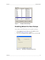
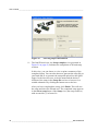
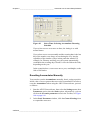
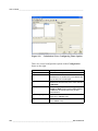
The setups you create with the Wizard tool appear in the Select Setup
frame of the Setup view (that is, in the setup archives) with an asterisk
(*) in front of them as shown in Figure 9 on page 33. The asterisk
indicates that the setup can be further edited with the Wizard tool.
Setups created with the Wizard tool can also be modified with Lizard
software, but once they are modified and saved with Lizard software,
the asterisk disappears and the setups can no longer be opened with the
Wizard tool.
By default, all new setups are set to be created with the Wizard tool. If
you do not wish to use the Wizard tool, you can disable it by following
the instructions in section Enabling Wizard for New Setups on page 33.
32 ___________________________________________________________________M210785EN-E
Chapter 3 ____________________________________________________________ Getting Started
Figure 9
0511-002
Example of Wizard Setup
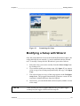
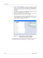
Enabling Wizard for New Setups
If you wish to use the Wizard tool, you can enable it as follows:
1.
Choose Options from the View menu. The Options window,
presented in Figure 10 on page 33, appears.
2.
Select the Use Wizard for new setups check box and click OK.
Figure 10
0802-060
Disabling or Enabling Wizard Tool
VAISALA _______________________________________________________________________ 33
User’s Guide ______________________________________________________________________
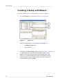
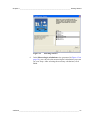
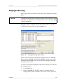
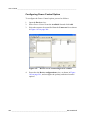
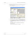
Creating a Setup with Wizard
To create and fill out a new Wizard setup, proceed as follows:
1.
Go to the Setup view as shown in Figure 11 on page 34.
Figure 11
0802-051
Setup View
The following numbers refer to Figure 11 on page 34:
2.
1
=
Configure Setup frame
2
=
Setup archives
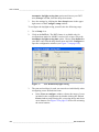
Click New. The New Setup window opens; see Figure 12 on page
35. Name the new setup and select the QML logger version
number. The name must be unique and no longer than eight
characters. Lizard automatically suggests the highest possible
version number. Enter the name and, if necessary, change the
version number, and click OK.
34 ___________________________________________________________________M210785EN-E
Chapter 3 ____________________________________________________________ Getting Started
Figure 12
0802-108
NOTE
New Setup Window
If the version you select is higher than the one your QML logger
actually has, the logger will not run the setup file.
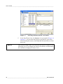
3.
The new setup then appears as the current setup in the Configure
Setup frame. Enter a description for the setup into the Description
box; refer to Figure 11 on page 34.
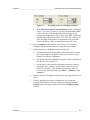
4.
Open the first Wizard view by clicking Next on the lower right of
the view.
If you have disabled the Wizard tool but wish to use it for this
setup, you can open the first view of the Wizard tool by selecting
Wizard from the View menu. Refer to Figure 13 on page 36.
If you have disabled the Use Wizard for new setups option but
wish to enable it again, refer to section Enabling Wizard for New
Setups on page 33.
VAISALA _______________________________________________________________________ 35
User’s Guide ______________________________________________________________________
Figure 13
0802-109
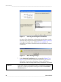
5.
NOTE
Selecting Wizard from the View Menu
In the first Wizard view, the Sensors view presented in Figure 14
on page 37, you can select the sensors you want for your setup.
After selecting the sensors, click Next and Wizard will move to the
next view.
The selections made in this view determine the options available in the
following views. For example, the sensors selected here will determine
the calculations displayed in other views.
36 ___________________________________________________________________M210785EN-E
Chapter 3 ____________________________________________________________ Getting Started
Figure 14
0711-045
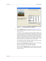
6.
Selecting Sensors
In the Meteorologic calculations view (presented in Figure 15 on
page 38), you can select the meteorological calculations you want
for your setup. After selecting the necessary calculations, click
Next.
VAISALA _______________________________________________________________________ 37
User’s Guide ______________________________________________________________________
Figure 15
0711-046
Selecting Meteorological Calculations
As some of the calculations are dependent on each other, certain
selections may cause the message presented in Figure 16 on page
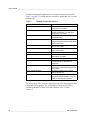
38 to appear. In such a case, check Table 5 on page 45 for
information on Wizard calculation intervals and add the required
calculations.
Figure 16
0309-023
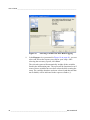
7.
NOTE
Data Missing Message
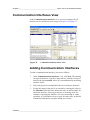
In the Statistical Calculations view presented in Figure 17 on
page 39, you can select the statistical calculations you want for
your setup. You can select 10-minute, 1-hour, and 24-hour
calculations. After selecting the necessary calculations, click Next.
If the setup includes a precipitation gauge, an additional configuration
option for a 6-hour precipitation sum appears under the Statistical
Calculations box.
38 ___________________________________________________________________M210785EN-E
Chapter 3 ____________________________________________________________ Getting Started
Figure 17
0711-047
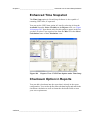
8.
Selecting Statistical Calculations
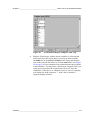
In the Loggable data views, presented in Figure 18 on page 40,
you can select the logged variables for ten-minute, one-hour, and
24-hour intervals.
Note that you can use log groups to group log data according to, for
example, the intervals when the data is being logged. Thus one log
group can contain the variables logged at one-minute intervals and
so forth. Using log groups can also be useful if you define that a
change in a certain variable will cause all variables in a specific log
group to be logged. For example, an alarm will then trigger logging
of data somehow involved with the source of the alarm.
The estimated size of the log groups and the time that they will be
stored are indicated above the selection box.
Select the Use external memory card check box if you want the
log files to be stored on the external memory card.
After selecting the necessary variables, click Next.
There are similar Loggable data views also for the 10-minute and
24-hour intervals. The interval in question is indicated in the upper
right of each view.
VAISALA _______________________________________________________________________ 39
User’s Guide ______________________________________________________________________
Figure 18
0711-048
9.
Selecting Variables for One-Hour Logging
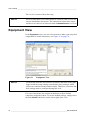
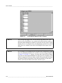
In the Reports view (presented in Figure 19 on page 41), you can
select and fill out the reports you want for your setup. After
selecting the necessary reports, click Next.
The selected reports will automatically include all the variables
listed in the information pane. The report will be functional even if
some of these variables have not been selected while creating the
setup. The variables that have not been selected (and that are thus
not available) will be indicated in the report as slashes (//).
40 ___________________________________________________________________M210785EN-E
Chapter 3 ____________________________________________________________ Getting Started
Figure 19
0711-049
Selecting Reports
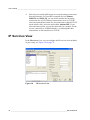
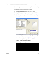
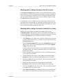
10. In the Report Destination view (presented in Figure 20 on page
42), you can select a destination for the reports selected in the
previous view. You can choose between the COM0 and COM1
ports. You can also define an optional pollstring for each report.
NOTE
If you enter a pollstring in Wizard, timed sending of reports is no
longer enabled.
After selecting the necessary destinations, click Next.
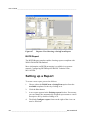
NOTE
A separate Report Destination view opens for each report that has
been selected.
VAISALA _______________________________________________________________________ 41
User’s Guide ______________________________________________________________________
Figure 20
0711-050
Selecting Report Destination
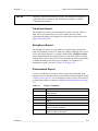
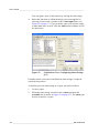
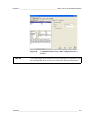
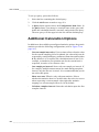
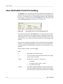
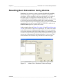
11. The final Wizard view, the Setup complete view presented in
Figure 21 on page 43, indicates the completion of Wizard setup
creation.
In this view, you can choose to view or print a summary of the
completed setup. You can also choose to generate the setup file on
your hard disk or to generate the setup and upload it to the QML
logger. In the last two cases, write the name and the desired
location of the setup in the Setup file text box or browse for a
suitable alternative by clicking the button next to the box.
After you have completed the setup, click Finish. This will save
the setup and close the Wizard tool. The completed setup appears
in the Select setup frame of the Setup view (the setup archives)
with an asterisk (*) in front of it.
42 ___________________________________________________________________M210785EN-E
Chapter 3 ____________________________________________________________ Getting Started
Figure 21
0804-043
Completing the Setup
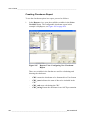
Modifying a Setup with Wizard
Only the setups that have been created with the Wizard tool, that is, the
setups indicated by an asterisk (*), can be modified with the Wizard
tool. To modify a setup with the Wizard tool, proceed as follows:
NOTE
1.
Select the setup you want to modify from the Select Setup frame
by clicking on it.
2.
If you want to modify an existing setup, click Open. If you want to
create a copy of an existing setup and modify the copy, click Open
Copy.
3.
The selected setup or a copy of the setup appears in the Configure
setup frame. The program automatically generates a name for the
copy that is slightly different from the original.
4.
If necessary, you can edit the name, the description, and the version
of the setup.
If the version you select is higher than the one your QML logger
actually has, the logger will not run the setup file.
VAISALA _______________________________________________________________________ 43
User’s Guide ______________________________________________________________________
5.
Start modifying the setup by clicking Next. This will automatically
open the first Wizard view.
If you have disabled the Wizard tool but wish to use it for this
setup, you can open the first view by selecting Wizard from the
View menu; refer to Figure 13 on page 36.
If you have disabled the Use Wizard for new setups option but
wish to enable it again, refer to section Enabling Wizard for New
Setups on page 33.
6.
Modify the setup with the Wizard tool in the same way as you
created a new setup with the Wizard tool. For detailed instructions
on this, refer to section Creating a Setup with Wizard on page 34
(starting from step 5).
You can make more detailed modifications to your setups with
Lizard Setup Software, but once you have saved the modifications
made with Lizard, you can no longer open the setups with the
Wizard tool.
44 ___________________________________________________________________M210785EN-E
Chapter 3 ____________________________________________________________ Getting Started
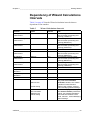
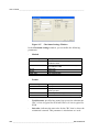
Dependency of Wizard Calculations
Intervals
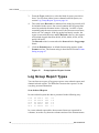
Table 5 on page 45 lists the Wizard calculation intervals that are
dependent on one another.
Table 5
Wizard Calculations Intervals
Function
Inputs
Interval
Note
Air temperature
measurement
QMH101/102
10 s
Relative humidity
measurement
QMH101/102
10 s
Barometric pressure
measurement
PMT16A
10 s
1 min average used as instant
value for further processing and
reporting (TAStat1m).
1 min average used as instant
value for further processing and
reporting (RHStat1m).
1 min average used as instant
value for further processing and
reporting (PAStat1m).
Rain measurement
Global radiation
measurement
QMR101/102
QMS101/102 or CM6B
60 s
10 s
Net radiation
measurement
QMN101
10 s
Soil/Water temperature
measurement
QMT103/110
10 s
Wind measurement
Dewpoint temperature
calculation
Frostpoint temperature
calculation
Heat index calculation
QFE calculation
QMW101/110
QMH101/102
1s
60 s
QMH101/102
60 s
QMH101/102
PMT16A
60 s
60 s
QMH101/102
Pslevel setting
QFF calculation
PMT16A
QFE calculation
QMH101/102
Altitude setting
60 s
1 min average used as instant
value for further processing and
reporting (SRStat1m).
1 min average used as instant
value for further processing and
reporting (NRStat1m).
1 min average used as instant
value for further processing and
reporting (TGStat1m).
Pressure sensor level [m] is set
using AWS Client Common
parameters window; see Vaisala
HydroMet™ Data Collection
Platform User’s Guide, Volume 1,
section Modifying Station Settings.
Station altitude [m] is set using
AWS Client Common parameters
window; see Vaisala HydroMet™
Data Collection Platform User’s
Guide, Volume 1, section Modifying
Station Settings.
VAISALA _______________________________________________________________________ 45
User’s Guide ______________________________________________________________________
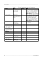
Table 5
Wizard Calculations Intervals (Continued)
Function
Inputs
Interval
Note
QNH calculation
PMT16A
QFE calculation
Altitude setting
60 s
Sunshine duration
QMS101/102
60 s
Station altitude [m] is set using
AWS Client Common parametes
window; see Vaisala HydroMet™
Data Collection Platform User’s
Guide, Volume 1, section Modifying
Station Settings.
Station parameters lat and lon are
set to installation location's latitude
and longitude [deg] using AWS
Client Common parameters
window; see Vaisala HydroMet™
Data Collection Platform User’s
Guide, Volume 1, section Modifying
Station Settings.
Uses 10 min average wind speed
for calculation.
Station parameters lat
and lon
Wind chill calculation
Wind calculation
10 min and 1 hour
average, minimum and
maximum statistics
24 hour average,
minimum and maximum
statistics
10 min, 1 and 6 hour
sum statistics
24 hour sum statistic
Logging
WD30 wind report
60 s
QMW101/110
QMH101/102
Wind calculation
QMW101/110
As selected
15 s
60 s
As selected
24 h
QMR101/102
60 s
QMR101/102
As selected
24 h
Calculated at 06:00 hours.
10 min, 1
and 24 hours
2s
QMW101/110
Wind calculation
WD30 temperature and QMH101/102
humidity report
YourWay wind report
QMW101/110
Wind calculation
Calculated at 00:00 hours.
30 s
3s
46 ___________________________________________________________________M210785EN-E
Chapter 3 ____________________________________________________________ Getting Started
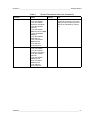
Table 5
Wizard Calculations Intervals (Continued)
Function
Inputs
YourWay PTU report
30 s
QMH101/102
1-hour TA statistic
1-hour RH statistic
Dewpoint calculation
1-hour DP statistic
PMT16A
1-hour PA statistic
QMS101/102 or CM6B
1-hour SR statistic
QMN101
1-hour NR statistic
QMT103/110
1-hour TG statistic
QMR101/102
1-hour PR sum
24 hour PR sum
60 s
QMH101/102
1-hour TA statistic
1-hour RH statistic
Dewpoint calculation
1-hour DP statistic
PMT16A
1-hour PA statistic
QMW101/110
Wind calculation
QMR101/102
1-hour PR sum
24-hour PR sum
Total report
Interval
Note
All the listed sensors do not have to
be present to make the YourView
display functional. Missing sensor
data will be indicated by slashes
( / ).
VAISALA _______________________________________________________________________ 47
User’s Guide ______________________________________________________________________
48 ___________________________________________________________________M210785EN-E
Chapter 4 ____________________________________________ Basic Use of Lizard Setup Software
CHAPTER 4
BASIC USE OF LIZARD SETUP
SOFTWARE
This chapter provides instructions for the basic use of Lizard Setup
Software which is used to modify the software parameters and
operation of the QML logger. Detailed information on configuring the
sensors and telemetry options is presented in Vaisala HydroMet™ Data
Collection Platform User’s Guide, Volume 3.
Starting Lizard Setup Software
You can start Lizard Setup Software by using either of the following
two alternatives:
1.
Double-click the Lizard icon on your desktop.
or
2.
Click the Start button and select Programs - Vaisala - MAWS
Lizard.
VAISALA _______________________________________________________________________ 49
User’s Guide ______________________________________________________________________
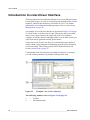
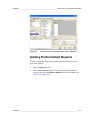
Introduction to Lizard User Interface
The basic function of Lizard Setup Software is to create different setups
for the QML logger. A setup is created by going through all the Lizard
modules, which in this manual are referred to as views. For further
information on creating and modifying setups, refer to section Setup
Management on page 56.
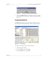
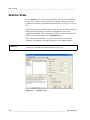
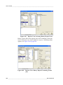
An example view of the user interface is presented in Figure 22 on page
50. Work in the views from left to right. This means that you usually
have to select some items in the upper left of the view and then
configure or edit the details on the right of the view. In other words, you
work from left to right and towards greater detail.
On the lower left of each view there is an information pane which is
used for both a page help and for displaying general help information
on selected items. These help systems will be further discussed in
section Online Help on page 55.
Configurable items in bold print can usually be edited. For example,
you can rename parameters by double-clicking on the item.
Figure 22
1004-059
Example View of User Interface
The following numbers refer to Figure 22 on page 50:
1
=
Toolbar
2
=
Information pane
50 ___________________________________________________________________M210785EN-E
Chapter 4 ____________________________________________ Basic Use of Lizard Setup Software
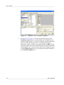
Menu Bar
The menu bar in the user interface views contains five menus: File,
View, Setup, Utility, and Help. Most of the features provided by the
menus are also available elsewhere in the application.
The File menu includes the Import Setup and Export Setup functions,
which are further discussed in sections Importing a Setup on page 61
and Exporting a Setup on page 60, as well as the Import multiple and
Export All functions, which are discussed in sections Importing
Multiple Setups on page 62 and Exporting All Setups on page 61. This
menu also includes an Exit function.
The View menu includes all the modules or views as items, which
means that you can also enter the views from this menu. This menu also
includes an Options feature, the functions of which are further
discussed in section Changing the User Level to Advanced on page 141
and section Generating and Uploading a Setup on page 138. In the View
menu, you can also start the Wizard tool for creating new setups. For
more information on the Wizard, see section Wizard Tool on page 31.
The Setup menu includes the Generate, Generate setup with script
comments, and Save features. These features are further discussed in
sections Saving Changes on page 54 and Generating and Uploading a
Setup on page 138. The Setup menu also contains the advanced features
Script Viewer for viewing and modifying QML logger scripts, Subsets
for parametrization of setup components, and Parameter Sets for
configuring QML logger parameter sets. For more information on
parameter sets, refer to Vaisala HydroMet™ Data Collection Platform
User’s Guide, Volume 3.
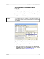
The Utility menu includes the Copy and Paste functions which are
further discussed in sections Copying Calculations on page 85 and
Copying Reports on page 117. A third function, Wizard, becomes
available in the Measurement view if you select a generic 24-bit
measurement; then, selecting the Wizard function will display an
additional selection dialog.
The Help menu enables you to access program version information.
VAISALA _______________________________________________________________________ 51
User’s Guide ______________________________________________________________________
Selecting User Level
Lizard Setup Software includes the following user levels:
-
Normal user level is the default option. It allows you to create a
setup in a very fast and simple way, using default options for most
parameters. This option is recommended for all users.
-
Advanced user level is for experienced users only. On this level,
you will have access to more parameters, thus allowing you to
create a setup with more advanced features. For further
information on these advanced features, refer to Vaisala
HydroMet™ Data Collection Platform User’s Guide, Volume 3.
To change the user level, proceed as follows:
NOTE
1.
In the View menu, choose Options.
2.
Under the General tab, select the desired user level and click OK.
Changing the user level from Normal to Advanced brings up more
alternatives for your selection, thus requiring a profound
understanding of the behavior of the system.
Toolbar
Figure 23
0711-001
Lizard Setup Software Toolbar
Each of the buttons on the toolbar of a user interface view opens another
view of Lizard. By default, Lizard opens in the Setup view.
52 ___________________________________________________________________M210785EN-E
Chapter 4 ____________________________________________ Basic Use of Lizard Setup Software
The buttons and the corresponding views they open are as follows:
Setup Management view; see section Setup Management on
page 56.
Optional Hardware view; see section Optional Hardware View
on page 63.
Devices view; see section Devices View on page 66.
Device Configurations view; see section Device Configurations
View on page 67.
Communication interfaces view; see section Communication
Interfaces View on page 71.
IP services view; see section IP Services View on page 72.
Equipment view; see section Equipment View on page 74.
Additional sensors view; see section Additional Sensors View
on page 77.
Measurements view; see section Measurements View on page
79.
Calculations view; see section Calculations View on page 81.
Advanced view; see section Advanced View on page 89.
Logging view; see section Logging View on page 90.
Reports view; see section Reports View on page 102.
VAISALA _______________________________________________________________________ 53
User’s Guide ______________________________________________________________________
Communications view; see section Communications View on
page 120.
Alarms view; see section Alarms View on page 126.
Timers view; see section Timers View on page 131.
Setup Information view; see section Setup Information View on
page 134.
Buttons
All setup views contain several basic buttons on the lower right. These
include the PageHelp button, Next and Back buttons, and Generate
buttons. The Timer view, additionally, contains the Set Default button.
The PageHelp button retrieves the Page help as described in section
Page Help on page 55. The Next and Back buttons allow you to
navigate by easily moving between the different setup views. You can
also navigate using the toolbar.
The Generate button generates the current setup, in order to upload it
to the weather station.
In the Timer view, use the Set Default button to retrieve the Lizard
default settings after incorrect alterations.
Saving Changes
When you modify settings in normal operation, the changes are
automatically saved as you move on to the next setting.
Although modifications are automatically saved into the setup, the
setup is not automatically saved into the archives. To save the current
version into the setup archives, proceed as follows:
1.
Return to the Setup view.
2.
Click the Save Setup button located in the Configure setup frame.
54 ___________________________________________________________________M210785EN-E
Chapter 4 ____________________________________________ Basic Use of Lizard Setup Software
It is not necessary to save the setup in the archives every time you
change a setting. Save the setup when you particularly want to archive
it, for example, when you have finished modifying the entire setup.
Online Help
Currently Lizard Setup Software offers two ways of getting online help:
1.
Information pane, which displays general help information on
selected items
2.
Page help
Information Pane
When you click on an item, a brief description of the item appears in the
information pane on the lower left. The information pane displays
helpful information and details on selected items in the view. For an
example of the information pane, refer to Figure 22 on page 50.
Page Help
When you open each setup view, the information pane on the lower left
of the view, shown in Figure 22 on page 50, displays a page help. This
is a brief description of the particular view and its functions. You can
later retrieve the page help by clicking the PageHelp button.
User Comments
You can add your own comments in each Lizard view. Click User
comments on this page below the information pane to add viewspecific comments. The maximum number of characters allowed is 255.
VAISALA _______________________________________________________________________ 55
User’s Guide ______________________________________________________________________
Setup Management
The Setup view opens by default when you open Lizard Setup
Software; see Figure 24 on page 56. In this view you can open, manage
and modify different setups. In addition, you can manage setup archives
and import or export separate setups from one Lizard to another.
Figure 24
1004-060
Setup View
Layout of the Setup View
The Setup view is divided into two parts. The Select Setup frame on
the left acts as setup archives, whereas the Configure Setup frame on
the right displays the current setup.
Select Setup (Setup Archives)
The Select Setup frame, in other words, the setup archives, list all the
different setups that have been created and archived for the Lizard
software in use. A brief description of each setup in the archives can be
viewed by clicking on the setup of interest. The description appears in
the information pane, below the setup archives frame.
56 ___________________________________________________________________M210785EN-E
Chapter 4 ____________________________________________ Basic Use of Lizard Setup Software
The Select Setup frame is divided into three lists. The Name list
contains the names of the setups. The names must be unique and no
more than eight characters long. An asterisk (*) in front of a setup name
indicates that the setup has been created with the Wizard tool. For
further information on creating setups with the Wizard tool, refer to
section Wizard Tool on page 31.
The Maws logger list displays the QML logger hardware version for
which the setup was configured. Hardware version QML201B can run
software versions up to and including 8.00, but QML201C can only run
8.0 or higher.
The Maws version list displays the QML logger software version for
which the setup was configured. This setting affects, for example, the
selection of sensors and calculations. If you have selected the correct
version, you cannot make selections with your Lizard that your QML
logger with the particular software version does not support. If the
version you select is higher than the one your QML logger actually has,
the logger will not run the setup file. Also note that the Lizard views for
configuring IP-based communications are not visible for setups created
for QML logger versions earlier than 6.00.
The Last Saved list contains the date and time of the setup versions, and
the Saved by list the user name of the person who last saved the setup
(based on Windows user names).
Configure Setup (Current Setup)
The Configure Setup frame displays the setup currently being
modified. It also gives almost the same basic information, name,
description, and the version of the current setup as the setup archives do.
Opening a Setup
There are different ways to open a setup. You can create an entirely new
setup, create a copy of an existing setup for modification, or open an
existing setup for modification or uploading. You can also create a
setup with the Wizard tool. For further information on using the Wizard
tool, see section Wizard Tool on page 31.
VAISALA _______________________________________________________________________ 57
User’s Guide ______________________________________________________________________
Creating a New Setup
To create a new setup, proceed as follows:
NOTE
1.
Click New.
2.
A New Setup window opens asking you to name the new setup and
to select the version number. The name must be unique and no
longer than eight characters. Lizard automatically suggests the
highest possible version number. Enter the name and, if necessary,
modify the version number, and click OK.
If the software version number you select is higher than the one your
QML logger actually has, the logger will not run the setup file.
3.
The new setup appears as the current setup in the Configure Setup
frame. Enter a description for the setup into the Description box.
You have created a new, empty setup, which includes only the basic,
fixed elements. You can now modify the setup by proceeding to the
following views.
Creating a Copy for Modification
To create a setup by copying an existing one for modification, proceed
as follows:
NOTE
1.
Select the setup you want to modify from the Select Setup frame
by clicking on it.
2.
Click the Open Copy button.
3.
The existing setup is copied and it appears in the Configure Setup
frame with a slightly different name.
4.
If necessary, you can edit the name, the description, and the version
of the setup.
If the software version number you select is higher than the one your
QML logger actually has, the logger will not run the setup file.
You have now created a new setup by copying an existing one. This
setup consists of the settings of the previous setup. You can modify the
58 ___________________________________________________________________M210785EN-E
Chapter 4 ____________________________________________ Basic Use of Lizard Setup Software
settings by proceeding to the following views. The original setup
remains in the archives unchanged.
Opening an Existing Setup
To open an existing setup for modification or uploading, proceed as
follows:
NOTE
1.
Select the setup you want to modify or upload from the Select
Setup frame by clicking on it.
2.
Click Open.
3.
The selected setup appears in the Configure Setup frame.
4.
If necessary, you can edit the name, the description, and the version
of the setup.
If the software version number you select is higher than the one your
QML logger actually has, the logger will not run the setup file.
You have now created a new setup by modifying an existing one
without making a copy of it. You can modify the setup further by
proceeding to the following views. Note that the original setup still
exists in the archives, but saving the modified setup will overwrite the
original with the new modifications.
Saving a Setup
In normal operation, when you modify settings, your changes are
automatically saved as you move onto the next view.
Although modifications are automatically saved into the setup, the
setup is not automatically saved into the archives. To save the current
version into the setup archives, return to the Setup view and click the
Save Setup button located on the upper right of the Configure Setup
frame.
It is not necessary to save the setup in the archives every time you
change a setting. It is only necessary when you particularly want to
archive the setup, for example, when you have finished modifying the
entire setup.
VAISALA _______________________________________________________________________ 59
User’s Guide ______________________________________________________________________
Deleting a Setup
To delete a setup, proceed as follows:
1.
Select the setup you want to delete from the Select Setup frame by
clicking on it.
2.
Click the Delete button.
The setup is permanently deleted.
Exporting a Setup
The Lizard setup database is very large and often cannot be transported
on a disk or via e-mail. For this reason, Lizard Setup Software contains
a system specifically designed for exporting and importing individual
setups from one Lizard to another.
To export a setup, proceed as follows:
1.
Open the setup to be exported by selecting it from the Select Setup
frame and clicking the Open button. This is an important step as
you can only export the current setup.
2.
Click File on the menu bar and select Export setup.
3.
The Export setup window opens. Click the Select button to select
the export folder.
4.
The Export current setup to file window opens asking you to
select where you want the setup exported. Make the selection and
click Save.
You have now exported the current setup. A copy of the setup will
remain in the archives. After the setup has been exported, it can be
copied onto a disk or sent via e-mail.
60 ___________________________________________________________________M210785EN-E
Chapter 4 ____________________________________________ Basic Use of Lizard Setup Software
Importing a Setup
To import an exported setup, proceed as follows:
NOTE
1.
Click File on the menu bar and select Import setup.
2.
The Import setup from file to current window opens asking you
to choose the setup to be imported. Select the setup and click Open.
3.
The New Setup window opens asking you to name the setup and
to select the version number. Enter the name and the version
number and click OK.
4.
The setup is imported to replace the current setup.
Importing a setup may take a while.
5.
Click the Save Setup button in the Configure Setup frame to save
the setup in the archives.
Exporting All Setups
With the Export All function, you can export all the setups from the
setup archives. This is useful for backup purposes.
NOTE
Before starting the export procedure, make sure that the destination
folder does not contain earlier copies of the setup files, as they will be
overwritten.
To export all setups, proceed as follows:
1.
Save the setup you have been configuring, as Lizard opens all
setups during the export procedure.
2.
Click File on the menu bar and select Export All.
3.
The Export setup window opens. Click the Select button to select
the export folder.
4.
The Browse for Folder window opens asking you to select the
export folder. Make the selection and click OK.
The setups are exported from the setup archives. Progress information
is shown in the information pane.
VAISALA _______________________________________________________________________ 61
User’s Guide ______________________________________________________________________
Importing Multiple Setups
With the Import Multiple function, you can import multiple setups to
the setup archives. This is useful for backup purposes and also for
providing compatibility between different Lizard versions.
NOTE
Before starting the import procedure, make sure that the setups you
select are not already in the setup archives, as they will be overwritten.
To import multiple setups, proceed as follows:
1.
Click File on the menu bar and select Import Multiple.
2.
The Import multiple files to archive window opens asking you to
choose the setups to be imported. Select the setups and click Open.
The setups are imported into the setup archives. Progress information is
shown in the information pane.
NOTE
Importing setups may take a while.
Making Backups
The Lizard setup archives are not designed for long-term data storage.
A better way to store information is to make backups by, for example,
exporting setups; see sections Exporting a Setup on page 60 and
Exporting All Setups on page 61.
NOTE
The information pane with general help information is available on all
the configurable items in case you need more detailed information.
62 ___________________________________________________________________M210785EN-E
Chapter 4 ____________________________________________ Basic Use of Lizard Setup Software
Optional Hardware View
In the Optional Hardware view, you can select the optional hardware
modules and configure them; see Figure 25 on page 63.
The hardware modules discussed in this section refer to the optional
QML logger hardware, that is, the hardware inside the logger, not the
sensors or any of the auxiliary equipment.
Figure 25
0905-094
NOTE
Optional Hardware View
Lizard Setup Software does not have an online connection to the QML
logger when the setup is being created and it does not know which
hardware is connected to the weather station. Therefore, all additional
hardware must be configured using this view. Also, all the added
optional hardware must be installed onto the weather station;
otherwise, the setup will not run.
VAISALA _______________________________________________________________________ 63
User’s Guide ______________________________________________________________________
Selecting Hardware
The Select Hardware frame on the upper left of the view is divided into
two list boxes. The Available list box provides a list of all the available
hardware modules. In the Connector/Module list box, the Connector
(block) list includes all the connectors to which the modules can be
connected. The Module list shows the connected modules.
The COM0 and COM1 communications ports already exist in the
hardware module list. Select the other modules.
To select the optional hardware used with the QML logger:
1.
Click on a hardware module in the Available list.
2.
Drag it into the correct place in the Module list or click on the
correct line and then click the Add button.
Removing Hardware
To remove optional hardware from the setup:
1.
Select the hardware module to be removed by clicking on the
appropriate row.
2.
Click the Remove button.
Configuring Hardware Modules
To make the setup work properly, the hardware module parameters
must have the correct settings. The list of configurable items may vary
depending on the selected module. For the basic hardware modules,
default settings have already been made. You do not necessarily need to
change these default settings.
NOTE
The following example illustrates the configuration of the fixed
COM0 communication port. The list of the configurable items varies
according to the module.
64 ___________________________________________________________________M210785EN-E
Chapter 4 ____________________________________________ Basic Use of Lizard Setup Software
To configure the settings of a communication port:
1.
Select the Service connection enabled option to enable service
connection. This allows you to access service functions, such as
software upload, log file download, and time setting.
It is recommended that you keep the service connection enabled at
least for the COM0 port (default).
2.
Set the basic communication parameters, data transfer speed, data
stop, bit stop, and parity in the Line parameters frame by selecting
the correct options from the corresponding combo boxes.
It is recommended that you keep the parameters for the COM0 port
in their default values: 9600, 8, 1, none.
3.
Choose the correct handshake options by selecting the desired
check boxes under Handshake options. The flow control options
using the XON/XOFF characters are individually selectable for
reception and transmission. You can also define the Receive
buffer limit (%): the receive flow control is activated/cleared
when the amount of free space in the receive buffer passes this limit
(percentage of total buffer size).
4.
Select the correct transmit control parameters in the Transmit
control frame. These parameters allow you to control external
hardware, such as the radio modem. You can enable transmit
control using the RTS signal, as well as choose the RTS output
polarity (normal or reverse).
In addition, you can switch on the transmitter of the radio before
actual transmission using the RTS signal with a configurable delay.
When the transmission has finished, the transmitter can be
switched off with another delay setting. Alternatively, this
parameter can be used to keep the radio transmitter enabled after
the last character has been transmitted.
5.
NOTE
Set the correct transmit and receive buffers in the Buffers frame.
This sets the internal buffer sizes in the QML logger. Normally,
these values should be left to their defaults. In case you have
changed the parameters but want to return to the default settings,
click the Set Default button.
The information pane with general help information is available on all
the configurable items in case you need more information.
VAISALA _______________________________________________________________________ 65
User’s Guide ______________________________________________________________________
Devices View
In the Devices view, you can select the communications devices to be
included in your setup and assign them to connectors; see Figure 26 on
page 66.
Figure 26
1004-061
Devices View
Selecting Communication Devices
To select a communications device, proceed as follows:
1.
Select the device to be added in the Available list and click Add.
2.
In the I/O connections frame, select a connector for the device
data and, if required, excitation signals. Note that for devices
connected to optional hardware modules, you must first add the
modules to your setup in the Optional hardware view.
66 ___________________________________________________________________M210785EN-E
Chapter 4 ____________________________________________ Basic Use of Lizard Setup Software
Removing Communication Devices
To remove a communications device from your setup, proceed as
follows:
1.
Select the device to be removed in the Selected list. Note that if the
device is used as a destination for reports, you must first disconnect
the reports sent to the device in the Communications view.
2.
Click the Remove button.
Device Configurations View
In the Device configurations view, you can configure the
communications devices to be included in your setup; see Figure 27 on
page 67.
Figure 27
1004-062
Device Configurations View
VAISALA _______________________________________________________________________ 67
User’s Guide ______________________________________________________________________
Non-TCP/IP Communication
Devices
Regardless of the external interface used (PSTN, GSM network, or
other), similar interface and parameters are used for configuring the
operation of the modem.
The modem control parameters are accessible in the Device
configurations view. Reports are linked to the modem in the Reports
view. You should link a report under Available reports to a
communications port (Port) with a modem (Device) attached to it.
Depending on the configuration, a call, SMS transmission, or Internet
operation may be initiated as soon as a new report is generated.
Alternatively, an inbound call and/or a poll may be required for
triggering the transmission.
TCP/IP-Based Communication
Devices
The TCP/IP-capable communication devices included in the list of
available equipment in the Devices view are listed in Table 6 on page
68.
Table 6
TCP/IP Communication Devices in Lizard
Device name
Description
Use
NullModem-IP
Used to connect QML to another
computer using RS232 cable. Note:
this null modem does not work with a
Windows PC.
Windows-specific version of the null
modem device
TCP/IP connection over GSM/GPRS
network using Siemens modem.
Tested to work with MC35i.
Connecting the QML logger locally to
a router, Linux PC, or similar devices
WinNullModem-IP
Siemens GPRS-IP
PSTN-IP
Connecting the QML logger locally to
a Windows PC
Connecting the QML logger to
remote systems using the GSM/
GPRS network as the ISP
connection
TCP/IP connection by dialing remote Connecting the QML logger to
modem(bank) using a PSTN modem. remote systems using the PSTN
Tested to work with DXM421.
network as the ISP connection
68 ___________________________________________________________________M210785EN-E
Chapter 4 ____________________________________________ Basic Use of Lizard Setup Software
NOTE
All devices listed above are for IP use only. None of them provides a
traditional, readable ASCII format modem connection. Non-IP
modem controls must be used if ASCII operating mode is required. For
configuration instructions on non-IP modems, refer to Vaisala
HydroMet™ Data Collection Platform User’s Guide, Volume 3,
Configuring Telemetry Options.
Common Modem Parameters
All different IP-modem types share the same configuration view:
Device configurations, shown in Figure 28 on page 69. This section
describes the parameters for basic use. For advanced modem
configuration, refer to section Configuring TCP/IP-based Telemetry in
Vaisala HydroMet™ Data Collection Platform User’s Guide,
Volume 3.
Figure 28
1004-063
Modem Configuration View
The top of the view shows the parameter set values associated with the
device. The parameter set and the configured component have the same
name. Parameters include station specific and commissioning time
settings, such as PIN codes. For certain modem types, this list may be
empty. Usually there is no need to add or remove parameters, but just to
change the value to an appropriate default value.
VAISALA _______________________________________________________________________ 69
User’s Guide ______________________________________________________________________
Common configuration parameters for modem controls are listed in
Table 7 on page 70. All parameters may not be applicable for a certain
modem type.
Table 7
Modem Control Parameters
Parameter
Use
Command delay
Delay in milliseconds between
successive commands.
Delay in milliseconds between
escape characters (+) used when
closing the connection.
Number of retries if opening the
connection fails.
Delay in milliseconds after a failed
connection attempt before attempting
a new connection.
Use power control output to reset the
device after failure.
Keep modem powered only with
active connection.
Answer incoming calls.
Provide additional operation
information to COM0.
Power control component
Delay in milliseconds between
modem power-up and the first
command.
Optional input component used to
monitor the carrier detect signal from
the modem.
Variable to monitor in the carrier
detect component.
Mask logically ANDed with value of
the carrier detect variable. If not set,
value 0 = CD off, else CD ON.
Escape delay
Dial retry count
Dial retry delay
Options/Reset after failure
Options/Preserve power
Options/Answer incoming
Options/Debug output
Power control
Powering delay
Carrier detect input
Carrier detect variable
Mask value for CD status
The lowest part of the view provides an interface for managing modem
commands and responses. For configuration instructions, refer to
Vaisala HydroMet™ Data Collection Platform User’s Guide,
Volume 3.
70 ___________________________________________________________________M210785EN-E
Chapter 4 ____________________________________________ Basic Use of Lizard Setup Software
Communication Interfaces View
In the Communication interfaces view, you can configure the IP
interfaces to be included in your setup; see Figure 29 on page 71.
Figure 29
1004-064
Communication Interfaces View
Adding Communication Interfaces
To add a communication interface, proceed as follows:
1.
In the Communications interfaces view, click New. The naming
for logical interfaces is fixed so that each new interface will get a
name in the format netifX, where X is an automatically increasing
interface index.
2.
Select the physical communication device used by the interface.
3.
Set the idle time for the device as needed by entering the value in
the Idle time field. Idle time defines the time, in milliseconds, for
which the interface is kept open when it is not being used. For
example, if opening the interface is a time consuming or costly
operation, it is advisable to keep it open for some time, so that all
transmitted information can pass during one session.
VAISALA _______________________________________________________________________ 71
User’s Guide ______________________________________________________________________
4.
Select if you want the QML logger to accept incoming connections
from this interface. For interfaces using the devices Siemens
GPRS-IP and PSTN-IP, you can select whether the incoming
connection uses a TCP/IP-based connection or not: for TCP/IP,
select the option Yes from the list; for connections without TCP/IP
(such as data calls), select the option Yes, without PPP. If you
select the latter option, you can use data calls, for example, for the
service connection to a GPRS interface, even though the data
transmission on the interface uses TCP/IP.
IP Services View
In the IP services view, you can configure the IP services to be included
in your setup; see Figure 30 on page 72.
Figure 30
1004-065
IP Services View
72 ___________________________________________________________________M210785EN-E
Chapter 4 ____________________________________________ Basic Use of Lizard Setup Software
Selecting IP Services
The available TCP/IP-based services and their uses are described in
Table 8 on page 73.
Table 8
TCP/IP-Based Services
Service
Use
FTP Client
HTTP Server
Sending reports to an FTP server
Displaying reports to be viewed by a
browser using the HTTP protocol
Synchronizing the QML logger clock
from an NTP server
Sending reports via e-mail
Enabling TCP/IP-based connections
to the QML logger and using these
for sending reports
Sending short messages using SMS.
Receiving short messages using
SMS.
Providing host name access to
logger with dynamic IP address.
Sending content, for example, XML
documents, to HTTP application
server.
Reading content, for example,
camera images from HTTP server.
NTP Client
SMTP Client
Virtual COM Port
SMS Messenger
SMS Handler
DynDNS Client
HTTP Messenger
HTTP Reader
To add an IP service to your setup, proceed as follows:
1.
In the IP services view, select the service from the Available list.
2.
Click the Add button.
For configuration instructions on each service, refer to Vaisala
HydroMet™ Data Collection Platform User’s Guide, Volume 3.
Removing IP Services
To remove a service from the setup, proceed as follows:
1.
Select the equipment to be removed by clicking on the appropriate
row in the Selected list box.
2.
Click the Remove button.
VAISALA _______________________________________________________________________ 73
User’s Guide ______________________________________________________________________
The service is removed from the setup.
NOTE
Services other than NTP Client cannot be removed if the services are
used as destinations for reports. The connections between the report
and the service have to be removed in the Communications view first.
Equipment View
In the Equipment view, you can select sensors to add to your setup and
assign them to certain connectors; see Figure 31 on page 74.
Figure 31
1004-066
NOTE
Equipment View
Lizard Setup Software does not have an online connection to the QML
logger when the setup is being created and it does not know which
sensors are connected to the weather station. Therefore, all sensors and
their settings must be configured using this view.
For your convenience, the sensors in the basic set have default
connectors assigned to them. To use the default settings, simply select
the Use defaults check box on the lower right of the view.
74 ___________________________________________________________________M210785EN-E
Chapter 4 ____________________________________________ Basic Use of Lizard Setup Software
Selecting Equipment
In the Equipment view, the Select sensor frame is divided into two list
boxes. The Available list box contains all the available sensors or
auxiliaries. The Selected list box contains two lists displaying both the
type and name of the selected item.
To select the equipment used with the QML logger, proceed as follows:
NOTE
All equipment are not automatically assigned a connector. If this is the
case, the connector has to be assigned manually, otherwise the
equipment is not connected and will not show anywhere else in the
setup.
1.
Select the sensor to be added from the Available list.
2.
Either drag it into the Selected list box, or click the Add button.
3.
To assign connectors automatically, select the Use Defaults check
box.
4.
Each selected item is then referred to with its type and is assigned
a unique name showing an identifying number. The name is
automatically highlighted suggesting that it can be changed to a
more descriptive one.
Removing Equipment
To remove a sensor from the setup, proceed as follows:
1.
Select the equipment to be removed by clicking on the appropriate
row in the Selected list box.
2.
Click the Remove button.
The equipment is removed from the setup.
NOTE
Equipment cannot be removed if its measurement results have been
used in calculations or reports somewhere in the setup. The
measurement results have to be removed from these places first.
VAISALA _______________________________________________________________________ 75
User’s Guide ______________________________________________________________________
Assigning I/O Connections
When the sensors and auxiliary equipment have been selected, they
need to be connected to the correct connectors. To make your task
easier, most sensors have been assigned a default connector, which does
not necessarily need to be changed.
NOTE
The connector names in the Connector list refer to the names on the
QML logger. To physically connect equipment to the QML logger,
refer to the installation instructions.
NOTE
If your system includes several sensors, the same connector may be set
as default for two sensors. In these cases, you will need to modify the
connector setting and perhaps also the internal sensor wiring.
To assign connectors automatically, proceed as follows:
1.
Make sure that you have selected the Use defaults check box
before adding any equipment.
2.
When a piece of equipment is added, the most commonly used
sensors are automatically assigned to the connectors, which match
the wiring of standard station sensors. Remember to follow this
setup when installing sensors on location.
If a piece of equipment does not have a default connector, assign it
manually.
To assign connectors manually, proceed as follows:
NOTE
1.
Double-click on the <None> text on the Connector list or on the
connector you want to replace. A combo box appears.
2.
Select the correct connector from the list.
Some sensors, such as the QMH air temperature and humidity probe,
will take up two connectors and are thus mentioned twice in the
Equipment list of the I/O Connections frame.
76 ___________________________________________________________________M210785EN-E
Chapter 4 ____________________________________________ Basic Use of Lizard Setup Software
Re-assigning Connectors
To quickly disconnect and reassign all the sensors or other equipment
already connected to the QML logger channels, proceed as follows:
1.
Click the Disconnect All button.
2.
Reassign the connectors either automatically by clicking the
Connect All button or manually as described in section Assigning
I/O Connections on page 76.
To disconnect only one sensor, double-click the text on the Connector
list and select <None> from the combo box displayed.
NOTE
The information pane with general help information is available on all
the configurable items in case you need more detailed information.
Additional Sensors View
In the Additional sensors view, you can select and configure the serial
sensors to be included in your setup; see Figure 32 on page 77.
Figure 32
1004-067
Additional Sensors View
VAISALA _______________________________________________________________________ 77
User’s Guide ______________________________________________________________________
Selecting Serial Sensors
To add a serial sensor or device to your setup, proceed as follows:
1.
In the Additional sensors view, select the sensor or device from
the Available list.
2.
Click the Add button.
For configuration instructions on each sensor or device, refer to Vaisala
HydroMet™ Data Collection Platform User’s Guide, Volume 3.
Removing Serial Sensors
To remove a serial sensor or device from the setup, proceed as follows:
1.
Select the sensor or device to be removed by clicking on the
appropriate row in the Selected list box.
2.
Click the Remove button.
The sensor or device is removed from the setup.
78 ___________________________________________________________________M210785EN-E
Chapter 4 ____________________________________________ Basic Use of Lizard Setup Software
Measurements View
In the Measurements view, you can configure measurements for the
sensors you selected and connected in the Equipment and Additional
sensors views; see Figure 33 on page 79.
The basic set of sensors is automatically configured. You do not
necessarily need to change the default values for the parameters. You
can skip this view altogether, unless you wish to edit the measurement
names or the validation parameters.
Figure 33
1004-068
Measurements View
Editing Measurement Names
The Select Measurement frame on the upper left of the view displays
a list of the equipment names, signal names, and automatically
generated measurement names. The measurements shown here
correspond to the sensors you have selected in the Equipment and
Additional sensors view. The equipment names and signal names
cannot be changed in this view. The only alteration you can make here
is to change the measurement name to a more descriptive one.
VAISALA _______________________________________________________________________ 79
User’s Guide ______________________________________________________________________
To edit the measurement name, proceed as follows:
1.
Double-click the name.
2.
Erase the old name and type in a new one. The name is
automatically saved when you press ENTER or click on another
measurement row.
The name may consist of the following characters: A ... Z, a ... z, 0 ... 9,
and _. No spaces are allowed.
The measurement names used should be unique, thus no name can refer
to more than one measurement in this setup.
NOTE
Since only the measurement name, instead of both the equipment
name and measurement name, will be used in the setup from this point
on, it is recommended that you change the name to one that is
meaningful to you and thus easy to remember.
Configuring Measurement
Parameters
Typically, you can configure only the validation values of the
parameters. These validation parameters set the limits for the
measurement values. If the measurement values exceed or go under
these limits, the measurements will be reported as missing.
Validation parameters include such values as the minimum and the
maximum values and the maximum change.
The basic set of sensors is automatically configured, so the values in the
Configure frame do not necessarily need to be changed.
If the Configure frame is empty, the measurement has no configurable
parameters.
In case you have changed the parameters but want to return to the
default settings, click the Set Default button.
NOTE
The information pane with general help information is available on all
the configurable items in case you need more detailed information.
80 ___________________________________________________________________M210785EN-E
Chapter 4 ____________________________________________ Basic Use of Lizard Setup Software
Calculations View
In the Calculations view, you can select and configure meteorological
calculations and unit conversions, as well as statistical and
miscellaneous calculations; see Figure 34 on page 81.
Every calculation the QML logger makes is based on some input data.
That is, when a calculation is configured, you inform the logger which
variables are used for producing a particular calculation. To make this
task easier, Lizard gives suggestions on the correct sources and
variables. Sources can be measurement names or names of components
that manage static parameters, whereas variables are the names of the
output. Sources can include one or several variables.
Figure 34
1004-069
Calculations View
Calculation Categories
Calculations have been divided into the following four categories:
meteorological calculations, unit conversions, statistical calculations,
and miscellaneous calculations. The initial input data for these
calculations comes from measurement algorithms, other calculations,
or from static parameters.
VAISALA _______________________________________________________________________ 81
User’s Guide ______________________________________________________________________
Meteorological Calculations
In this category, you are selecting and configuring calculations for
derived quantities.
Some calculations, such as the wind calculation, provide two
calculation options. These options include the simple, quick
calculations that are fast to configure and the generic ones that offer
more possibilities but are more complex and laborious. The information
pane includes more detailed information on the differences between
these calculation options.
For more information on meteorological calculations, refer to the
related Technical References.
Unit Conversions
All the internal calculations within the QML logger are done in SI units.
With unit conversion calculations, you can convert the internally used
SI units to desired units for logged or reported values. For example, you
can convert hPa into mmHg.
NOTE
Only SI units can be used for internal calculations. The converted
values cannot be used as input values for most calculations. These
values can only be used for logging and reports.
Arithmetic Operations
The conversion module also enables various arithmetic operations with
one or two operands, which can be any measured, calculated, or
manually entered parameters. The operations include: add, subtract,
multiply, divide, square root, power, logarithm, logarithm10, exponent,
absolute, sine, cosine, and tangent.
82 ___________________________________________________________________M210785EN-E
Chapter 4 ____________________________________________ Basic Use of Lizard Setup Software
Statistical Calculations
The statistical calculations also have a selection of quick calculation
sets. These quick calculation sets include:
-
Quick statistic (avg, min, max),
-
Quick statistic (sum), and
-
Quick statistic (dev).
The different statistical functions are described in Table 9 on page 83.
Table 9
Available Statistical Functions
Name
Description
Avg
Min
Max
Sum
Dev
Average value over given calculation period
Minimum value over given calculation period
Maximum value over given calculation period
Sum over given calculation period
Standard deviation over given calculation period
There are also timestamps available for the minimum and maximum
spans of the statistic calculation. The optional timestamps are listed in
Table 10 on page 83.
Table 10
NOTE
Timestamps for Statistical Calculations
Name
Description
MIN_H
MIN_M
MIN_S
MAX_H
MAX_M
MAX_S
Hour when the minimum was detected
Minute when the minimum was detected
Second when the minimum was detected
Hour when the maximum was detected
Minute when the maximum was detected
Second when the maximum was detected
The use of timestamps increases the use of the RAM memory,
therefore timestamps should only be used when absolutely necessary.
VAISALA _______________________________________________________________________ 83
User’s Guide ______________________________________________________________________
Miscellaneous Calculations
Miscellaneous calculations include, for example, an accumulator option
for calculating annual precipitation (see section Accumulator
Calculation with Predefined Reset Time on page 88). Furthermore, you
can select the Timer option to create timed events that are more freely
configurable than the timers set in the Timers view (see section Timers
View on page 131).
Setting up Calculations
To select a calculation, proceed as follows:
1.
Choose between Meteorological, Unit conversion, Statistical,
and Miscellaneous calculations by clicking the correct button
below the Available list box.
2.
Click on an item name in the Available list box.
3.
Either drag it into the Selected list box or click the Add button.
4.
The name of the selected calculation is automatically highlighted
suggesting that it can be changed to a more descriptive one.
To configure a calculation, proceed as follows:
1.
Click on a calculation in the Selected list box. The corresponding
editable text boxes appear in the Configure frame.
2.
Select the Source and the Variable for the parameters from the
corresponding combo boxes. Only the sources and variables with
suitable measurement units are shown.
NOTE
If a source has only one variable option, the variable will automatically
appear in the variable text box when the source is selected. If this is not
the case, a variable has to be selected from the combo box.
NOTE
The Configure frame of certain calculations, such as generic statistics,
includes an extra Configuration Item frame as shown in Figure 35 on
page 85. You can use the buttons in this frame to add and remove
configurable items as an Advanced user. For further information, see
section Generic Statistical Calculations on page 158.
84 ___________________________________________________________________M210785EN-E
Chapter 4 ____________________________________________ Basic Use of Lizard Setup Software
Figure 35
0112-022
Configuration Item Frame
Removing Calculations
To remove a calculation from the setup, proceed as follows:
1.
Select the equipment to be removed by clicking on the appropriate
row in the Selected list box.
2.
Click the Remove button.
The calculation is permanently removed from the setup.
NOTE
The information pane with general help information is available on all
the configurable items in case you need more detailed information.
Copying Calculations
The Utility menu contains a copy-paste feature which allows you to
copy-paste calculations either inside the setup or from one setup to
another.
VAISALA _______________________________________________________________________ 85
User’s Guide ______________________________________________________________________
Figure 36
0511-010
Utility Menu
To copy a calculation inside the setup, proceed as follows:
NOTE
1.
Open the calculation for editing.
2.
On the Utility menu, select Copy Calculation.
3.
On the Utility menu, select Paste.
4.
You can rename the copy. The default name for the copy is the
original name with the ending "_n" where n is a consecutive
number. For example, the first copy of the calculation
PMT16AMeas_24 will be named PMT16AMeas_24_1.
When making a configuration copy inside the setup, do not close the
configuration view between the Copy and the Paste commands. If you
close the view, you will disconnect all variable references as explained
below.
To copy a calculation from one setup to another, proceed as follows:
1.
Open the calculation for editing.
2.
In the Utility menu, select Copy.
3.
Open the Setup view.
4.
In the Setup view, open another setup or create a new setup.
86 ___________________________________________________________________M210785EN-E
Chapter 4 ____________________________________________ Basic Use of Lizard Setup Software
5.
Open the same view where you made a copy of the calculation.
6.
In the Utility menu, select Paste.
7.
As the latter setup does not necessarily contain the same variables,
all references to the variables have been lost (that is, all variable
references are empty) and you have to reconnect them. This
procedure is analogous to defining the input variables for a new
calculation.
Generic Wind Calculation
You can configure the sample interval of a generic wind calculation to
be either 0.25 s, 0.5 s, 1 s, or 2 s. The sample interval should match the
sampling rate defined for the wind sensor. For example, if you want to
calculate wind with 4 Hz (250 ms) sampling, you must set the
QMW101 measurement sampling rate to 250 ms (0.25 s) and the
calculation sampling interval to 0.25 s (250 ms); see Figure 37 on page
87.
Figure 37
0711-059
Calculations View: Selection of Sample Interval
VAISALA _______________________________________________________________________ 87
User’s Guide ______________________________________________________________________
Additional Parameter for Statistical
Calculation
The additional parameter for statistical calculations determines whether
the calculation starts only at the first complete interval. It is useful in
sum calculations, where the calculation is not allowed to take place until
the first complete interval begins. You must set this option if, for
example, you have a daily sum of precipitation referring to midnight
and you wish to calculate complete 24-hour periods only. Note,
however, that in such a case you miss the precipitation sum of the first
uncompleted day.
Figure 38
0711-060
Calculations View: Configuring Statistical
Calculation
Accumulator Calculation with
Predefined Reset Time
You can use an "Accumulator" option to add a source parameter to the
destination parameter in order to, for example, accumulate annual
precipitation in the system and to reset the calculation at a predefined
moment.
88 ___________________________________________________________________M210785EN-E
Chapter 4 ____________________________________________ Basic Use of Lizard Setup Software
The destination parameter is stored in the static parameters to maintain
its value over reset or power shutdown. In addition, the destination
parameter can be reset according to a predefined schedule. The
Accumulator is always incremented when the source variable is
measured.
For more detailed information on how to configure the Accumulator
component, see section Accumulator with Predefined Reset Time on
page 195.
Advanced View
In the Advanced view, you can use and configure advanced
functionality in your setup; see Figure 39 on page 89.
Figure 39
0905-090
Advanced View
Selecting Advanced Items
To add an advanced item to your setup, proceed as follows:
1.
In the Advanced view, select the specific item from the Available
list.
2.
Click the Add button.
VAISALA _______________________________________________________________________ 89
User’s Guide ______________________________________________________________________
Removing Advanced Items
To remove an advanced item from the setup, proceed as follows:
1.
Select the item to be removed by clicking on the appropriate row
in the Selected list box.
2.
Click the Remove button. The item is removed from the setup.
Logging View
In the Logging view, you can select what kind of information the QML
logger stores, as well as configure how often, in what way, and where
this information is stored; see Figure 40 on page 90.
Figure 40
0711-057
Logging View
90 ___________________________________________________________________M210785EN-E
Chapter 4 ____________________________________________ Basic Use of Lizard Setup Software
The logging process consists of the following stages:
1.
Setting up log groups.
2.
Selecting the items to be logged in each log group.
3.
Defining when the data is to be stored.
4.
Defining where the data is to be stored.
5.
Defining where the data is to be sent over an FTP connection.
Data can be logged either into the logger internal memory or onto
external memory cards.
NOTE
When storing (logging) data on an external memory card, the internal
log memory is used as a temporary storage before transferring files to
the card. Therefore, make sure that there is enough room in the internal
memory for all the files generated during the course of one day.
Setting Up Log Groups
You can use log groups to group log data according to, for example, the
intervals when the data is being logged. Thus one log group can contain
the variables logged at one-minute intervals and so forth. Using log
groups can also be useful if you define that a change in a certain variable
will cause all variables in a specific log group to be logged. For
example, an alarm will then trigger logging of data somehow involved
with the source of the alarm.
NOTE
The QML logger uses UTC time in data logging and managing log
files, not the local time.
The Log groups frame of the Logging view contains a Group/
Interval/Size list. The Group list includes all the log groups that you
have created. The Interval list displays the logging intervals, measured
in seconds, of the log groups. The Size list contains the automatically
estimated sizes of the created log groups. The sizes indicate how much
log memory each group will take up daily. The size of the internal
memory is approximately 3.3 MB, whereas the external memory can
run up to 2 GB.
VAISALA _______________________________________________________________________ 91
User’s Guide ______________________________________________________________________
NOTE
Size information can be calculated when all items in the log group are
in the form of numerical data. Otherwise, the text n/a will be displayed
in the size list.
To create a log group, proceed as follows:
1.
Click the New button below the Log groups frame.
2.
A log group with the next available name, starting from L0, is
created. The log group names are automatically assigned by Lizard
software and cannot be edited.
3.
Edit the logging interval of the created log group by doubleclicking on it.
Deleting Log Groups
To delete a log group from the setup, proceed as follows:
1.
Select the log group to be deleted by clicking on the appropriate
row in the in the Log groups frame.
2.
Click the Delete button.
The log group is permanently deleted from the setup.
Selecting Log Group Items
All the items that can be selected into a log group are listed in the
variable tree in the Select Variables frame. The items to be logged are
grouped under source names like files in a directory. To see the list of
items under a source, click on the plus (+) sign. To collapse the list,
click on the minus (-) sign.
To select an item to a log group, proceed as follows:
1.
Select the log group to which you want to add an item by clicking
on the appropriate row in the Log groups frame.
2.
Click on the item in the Select variables frame.
3.
Drag the item into the Selected log items frame or click the Add
button.
4.
The log item is listed in the Selected log items frame.
92 ___________________________________________________________________M210785EN-E
Chapter 4 ____________________________________________ Basic Use of Lizard Setup Software
Removing Log Group Items
To remove a log group item from the setup, proceed as follows:
1.
Select the log group item to be deleted by clicking on the
appropriate row in the Selected log items frame.
2.
Click the Remove button.
The log group item is removed from the log group.
Sorting Log Group Items
When you add items into a log group, the items appear at the bottom of
the list in the Selected Log items frame. If you wish to sort this list, for
example, to move later added items closer to the previously added ones,
you can do this with the sorting buttons presented below.
To move a log group item within the Selected log items frame, proceed
as follows:
0605-079
1.
Click on the row that lists the log group item to be moved.
2.
Click either of the sorting buttons until the item is moved to the
desired place.
Selecting Log Item Options
Table 11 on page 94 contains the possible log item options and provides
information on what is logged with each option and when the logging
occurs.
By default, the items are logged at a certain interval. You do not
necessarily need to change this default option. If you want to change the
VAISALA _______________________________________________________________________ 93
User’s Guide ______________________________________________________________________
default settings, you have to select the log item in question from the
Select Variables frame in order to do this.
Table 11
Description of Logging Possibilities
Log Item Option
Logged Items
Logging Occurs
Save this item every
time its value changes
Save this item every
time the log group is
saved
Use this item as a
trigger for saving log
group
Autonomous data
source
Only the selected
item(s) is (are) saved.
Every item in the log
group is saved.
When the selected
item(s) is (are) updated.
At an interval set by a
timer (default).
Every item (except the
selected one(s)) in the
log group is (are) saved.
Check this option only if
the item to be logged is
shell_log under
AdcShell.
When the selected item
is updated.
When user input is
processed.
Selecting Log Group Options
You can select different log group options in the frame below the
Remove button.
The frame is divided into two sections. The Storage section, which can
be opened by clicking the Storage button on the right, contains different
data saving issues. In the Report section, which can be opened by
clicking the Report button, you can form reports of the log group data.
Storing Log Group Data
The QML logger has approximately 3.3 MB of internal Flash memory
that can be used for logging. If you do not retrieve the data very often
and feel that the capacity of the internal memory is not sufficient, you
can also use external memory cards.
94 ___________________________________________________________________M210785EN-E
Chapter 4 ____________________________________________ Basic Use of Lizard Setup Software
Select your log destination from the Save log data to combo box under
Storage. You can choose between the internal and the external
memory:
-
If you choose the internal memory, the option /Log/ appears by
default in the Destination directory field below. This is the fixed
internal log memory, which cannot be changed.
-
If you choose the external memory, the option (sname) appears by
default in the Destination directory field below. The value of
sname comes from a static parameter which you can change in the
Setup window, or, after the setup is loaded to the logger, using the
AWS Client software. The value of sname denotes the directory on
the CF card into which the log files are stored.
The QML logger stores the gathered log information in daily files by
creating a daily file for each log group. The Number of days to
preserve log files option determines how many days these daily log
files are kept in the internal memory before they are automatically
deleted. You can also turn off this option, in which case the log files are
stored until the log memory is full.
Figure 41
0511-014
Log Group Options: Storage Section
Reporting Log Group Data
In the Reporting section, you can form time history tables of the log
group data to send out as reports. Note that if your QML logger software
version is lower than 3.02, the report section will be disabled and you
cannot access it.
When you start formatting a log group report, all the boxes in the frame
will be empty. To format the report, proceed as follows:
1.
In the Log Groups frame, select the log group for which the report
is.
2.
Click the Reporting tab.
VAISALA _______________________________________________________________________ 95
User’s Guide ______________________________________________________________________
3.
From the Type combo box, select the kind of report you wish to
form. You can form either scan or channel ordered reports; see
section Log Group Report Types on page 96.
4.
The value in the Records box indicates how many log records will
be included in the report. One record contains the log group data
stored at particular moment in time. Selecting 1 creates a report
containing only the most recent record, 2 the two most recent ones,
and so on. For example, if the log group has hourly records, the
report is sent at 06:00 hours, and the Records value is 6, the reports
will include logged data from 06:00, 05:00, 04:00, 03:00, 02:00,
and 01:00 hours.
The Records value is connected to the Interval in the Log groups
frame.
5.
Click the Default button. A default format string appears in the
Format text box. The format string is described in section Format
String on page 97.
Figure 42
0511-015
Group Options: Report Section
Log Group Report Types
You can form two types of log group reports: scan ordered reports and
channel ordered reports. The difference between the reports is in the
way they present information.
Scan Ordered Reports
In scan ordered reports the data is presented in the following way:
19.8
20.3
20.4
20.7
21.2
42
44
40
39
37
1031.6
1030.8
1030.1
1029.7
1029.5
201
264
258
221
211
2.0
1.8
1.6
1.3
1.7
In a scan ordered report table, the measured items are organized in
columns, in such a way that one column consists of the measurements
96 ___________________________________________________________________M210785EN-E
Chapter 4 ____________________________________________ Basic Use of Lizard Setup Software
of one item over a period of time. Oldest values appear in the first row,
and the most recent ones in the last.
Channel Ordered Reports
In channel ordered reports the data is presented in the following way:
19.8 20.3 20.4 20.7 21.2
42 44 40 39 37
1031.6 1030.8 1030.1 1029.7 1029.5
201 264 258 221 211
2.0 1.8 1.6 1.3 1.7
In a channel ordered report table, the measured items are organized in
rows, in such a way that one row consists of the measurements of one
item over a period of time.
Format String
The format of the log group report is defined by a default string that
follows the syntax of the C programming language with certain
extensions.
An example of a default format string is presented below, with a
description of its different parts.
%[//////]6.1f%[//////]6.1f%[//////]5d (...)
where
% =
Starts the field
[] =
Contain the characters for invalid data, for example, ////// or
missing
6
=
Indicates field width (number of characters)
.1
=
Indicates the number of decimals
f
=
Ends the field (of a decimal number)
d
=
Ends the field (of an integer number)
By default, the fields of the format string are separated by a space.
VAISALA _______________________________________________________________________ 97
User’s Guide ______________________________________________________________________
Sending Log Group Data over an
FTP Connection
You can specify that the log group you are creating is regularly sent to
a remote server over an FTP connection. This assumes that you have an
FTP server available to receive log data and that you have specified one
or more FTP clients in your QML logger setup file. For information on
how to configure FTP clients in the setup, see Vaisala HydroMet™
Data Collection Platform User’s Guide, Volume 3.
It is useful to have multiple FTP clients specified the logger setup. For
instance, if you have only one client and you use it to send both log files
(which tend to be large) and reports (which are smaller in size), an error
in sending the log file would block sending the report as well. However,
if you use one client to send logs and another to send reports, the report
might still get through even if sending the log had failed.
To specify an FTP connection for a log group, proceed as follows:
1.
In the Log Groups frame, select the log group for which you wish
to define an FTP connection.
2.
Click the FTP tab.
3.
From the Select FTP client drop-down menu, select the client you
wish to use for the connection.
4.
In the Destination directory text field, enter the directory on the
FTP server in which you wish to have your log group stored. Note
that you only need to enter the directory name; you specified the
server name in IP Services the when you created the FTP client for
the setup.
Figure 43
0805-002
Group Options: FTP Connection
98 ___________________________________________________________________M210785EN-E
Chapter 4 ____________________________________________ Basic Use of Lizard Setup Software
Sending Log Group Reports
The created log group reports cannot be sent in the Logging view;
instead, they are sent in the Reports view like other reports.
To send a log group report, set up a StringForm report and select the log
report file as one of the variables of the report. See Figure 44 on page
99. The preview function is not available with log group reports.
For further information on setting up and sending reports, see section
Reports View on page 102.
Figure 44
0711-062
Reports View Showing a Log Group Report
NOTE
If you are creating log group reports with setups from earlier Lizard
versions, you must delete the log groups and set them up again for this
function to work.
NOTE
The information pane with general help information is available on all
the configurable items in case you need more detailed information.
VAISALA _______________________________________________________________________ 99
User’s Guide ______________________________________________________________________
Unit Conversion in Logging
All internal calculations in the QML logger are done in SI units.
However, you can convert measured or calculated values to another unit
before storing data into the log memory. Typically, these conversions
are made from an SI unit to a US unit, for example, from meters per
second to miles per hour. There are several predefined conversions you
can select from the list. Only those specified for each unit are displayed.
For example, there is no conversion from Celsius to knots. In addition,
only those values can be converted whose unit is known. In most cases
of predefined sensors, Lizard knows the unit. For manual sensors and
generic sensors, you have to specify the unit manually. See section
Setting Unit and Conversion for Manual Sensors on page 162.
If you download a log file from the QML logger and convert it to a .csv
file, only the converted values can be seen in this file.
In order to make a conversion, select a Log item. Then select the unit
from the conversions available for that item in the Conversion list of
the Log item options frame. For example, in Figure 45 on page 100, a
Celsius to Fahrenheit conversion for a temperature measurement has
been selected.
Figure 45
0711-063
Logging View: Unit Conversion
100 __________________________________________________________________M210785EN-E
Chapter 4 ____________________________________________ Basic Use of Lizard Setup Software
Using External Memory Cards
The size of the external memory cards, or, Compact Flash cards,
supported by the QML logger ranges from 32 MB to 2 GB. Vaisala
offers 32 and 256 MB cards as a standard option. It is recommended that
you use only cards purchased from Vaisala that have been tested to
function in harsh environments.
NOTE
If the Compact Flash memory card has not been formatted, it must be
formatted before use.
In MAWS versions 6.00 and later, it is recommended that you format
the card in a Windows PC. The file system to use is FAT (not FAT32).
Also, do not select the quick format option.
To format the CF card in the QML logger, insert it into the CF slot of
the QML logger. Give the EXTFS ERASE command. After the card
has been formatted, you can remove it from the slot.
The external log memory acts as a storage for data that has been copied
or moved from the internal memory. The copying or moving is carried
out once a day, 30 seconds after midnight. Once the data has been
moved from the internal memory to the external memory card, no log
group reports can be sent from this data.
Automatic Erase for Compact Flash Card
The log group -specific setting Number of days to preserve log files
also affects the files stored to the external Compact Flash card. The
functionality is the same as for internal log memory, that is,
-
Files older than the selected value [days] are deleted automatically
-
Files are not erased, that is, the automatic clean-up is disabled
When files are stored to the external card, the internal memory is used
as the working memory for storing the log files of the current day. These
working files are moved to the external card each day just after midnight
when the new files have been opened for writing.
VAISALA ______________________________________________________________________ 101
User’s Guide ______________________________________________________________________
Reports View
In the Reports view, you can create, format, and manage reports that
contain text, measurement values, and calculated data; see Figure 46 on
page 102.
With Lizard Setup Software, you can create two basic types of reports:
table form (TableForm) and string form (StringForm) reports. Both of
these types are based on specific report templates. The table form
template is the best choice when you want to create a table-like report,
whereas string form offers you more freedom for formatting. Lizard
software also offers some preformatted report templates for complex
reports.
Figure 46
0711-064
Reports View Showing a TableForm Report
Report Templates
Lizard Setup Software provides two types of report templates: the table
form (TableForm) template and the string form (StringForm) template.
The table form and string form reports resulting from these templates
are different in appearance. They are also formed in a different way and
used for different purposes. Lizard also offers a few preformatted report
templates to make the creation of certain complex reports easier.
102 __________________________________________________________________M210785EN-E
Chapter 4 ____________________________________________ Basic Use of Lizard Setup Software
NOTE
In early Lizard Setup Software versions, the StringForm template is
called a FreeForm template and TableForm template is called a
TabularForm template.
TableForm Report
The TableForm report is most suitable for human viewing. This is a
table-like report consisting of several columns and rows with
explanatory headings. An example of a table form report is shown in
Figure 46 on page 102.
StringForm Report
The StringForm report is most suitable for transferring information
between computer systems. To make the editing of StringForm reports
easier, the report appears as a single column in the Configure report
frame. Depending on the settings, however, the final report is usually
displayed as a row or several rows. The StringForm report may include
a column heading but it has no row headings. An example of a
StringForm report is shown in Figure 47 on page 104.
Preformatted Report
In order to make the creation of some complex but frequently used
reports easier, Lizard provides the preformatted report templates listed
in Table 12 on page 103. For instructions on how to edit or fill out these
preformatted reports, see section Adding Preformatted Reports on page
113.
Table 12
Template
Report Templates
Use
DD50
Sends PTU, wind, and precipitation data to the DD50
Digital Display.
MetMan
Sends user selectable variables to MetMan software.
WD30 Wind
Sends instant wind data to the WIND30 display.
WD30 TA & RH Sends temperature and humidity data to the WIND30
display.
YourView wind Sends instant wind data to the YourView display software.
YourView PTU Sends PTU, radiation, and precipitation data to the
YourView display software.
Custom report Facilitates the creation of special-formatted reports, for
instance, HTML-form reports.
VAISALA ______________________________________________________________________ 103
User’s Guide ______________________________________________________________________
Figure 47
0711-065
Reports View Showing a StringForm Report
BUFR Report
The BUFR Report template enables forming reports compliant with
WMO FM-94 BUFR standard.
More information on BUFR messaging is available in a separate
manual, Configuring BUFR Reports MAWS Technical Note,
M211022EN.
Setting up a Report
To create a new report, proceed as follows:
1.
Choose either the TableForm or StringForm option from the
Available templates list box by clicking on it.
2.
Click the New button.
3.
A new report appears in the Existing reports list box. If necessary,
you can change the automatically assigned report name to a more
descriptive one by double-clicking on it.
4.
The blank Configure report frame on the right of the view can
now be filled out.
104 __________________________________________________________________M210785EN-E
Chapter 4 ____________________________________________ Basic Use of Lizard Setup Software
NOTE
You cannot switch the report template while creating or configuring a
report, but you can delete the current report and start a new one.
To edit an existing report, proceed as follows:
1.
Select the report from the Existing reports list box by clicking on
it.
2.
The selected report appears on the right of the view ready to be
edited.
Deleting a Report
To delete a report from the setup, proceed as follows:
1.
Select the report to be deleted by clicking on the appropriate row
in the Existing reports list box.
2.
Click the Delete button.
The report is permanently deleted from the setup.
Filling out Reports
At least in the case of table form reports, filling them out can include
two different tasks: inserting explanatory column and row headings into
the table and selecting the necessary variables for the report. To see
what the configured report looks like, click the Preview button.
Inserting Text into a Report
To create a proper table form report, you should enter both text and
variables into the Configure report frame. However, you cannot insert
them both in the same cell. To see the structure of an ordinary table form
report, refer to Figure 46 on page 102.
VAISALA ______________________________________________________________________ 105
User’s Guide ______________________________________________________________________
To insert text into a cell, proceed as follows:
1.
Click on the cell in which you wish to insert text. A cursor appears
in the Text text box of the Cell properties frame.
2.
Enter your text, for example, a column or a row heading. The text
you insert will also appear in the selected cell.
Selecting Variables for a Report
All the items that can be placed in a report are listed in the variable tree
in the Select Variables frame. The items are grouped under source
names like files in directories. To see the list of items under a source,
click on the plus (+) sign. To collapse the list, click on the minus (-)
sign.
To select an item to a report, proceed as follows:
1.
Select the item to be added to a report by clicking on it in the Select
variables frame.
2.
Either drag the item into a cell in the Configure report frame or
select a cell and click the Add button.
3.
The item is shown in a report cell.
The list of variables also includes items, such as time and date, and
special characters, such as <SOH> Start of Heading and <STX> Start
of Text. You can select these items from the variable tree under the
source name Reporting. These items do not take up a cell of their own,
but are added into an already filled cell, next to an existing text.
NOTE
The special characters in a report preview are often indicated by a
backslash preceding the character.
Removing Variables from a Report
To remove a variable from a report:
1.
Select a cell with the variable to be removed from the Configure
report frame.
2.
Click the Remove button. The variable is removed from the report.
106 __________________________________________________________________M210785EN-E
Chapter 4 ____________________________________________ Basic Use of Lizard Setup Software
Editing Reports
You can edit cells and reports in the Cell properties and Report
properties frame. The properties can be viewed alternatively by
clicking the corresponding buttons below the frame.
Editing Cell Properties
NOTE
Most text boxes in the Cell properties frame have default values
which you do not necessarily need to change.
The Cell properties tab includes six text boxes.
The Text text box displays the text in the selected cell. Text marked
with gray, such as the variables, cannot be edited.
The Decimals text box displays the amount of decimals determined by
the variable in the selected cell. Correspondingly, the width of the cell
shown in Field width is determined by the widest variable.
The Alignment drop-down menu enables you to select whether the data
in the cell is aligned right (default), left, or centered.
In the Invalid data text box, you can enter the characters used to
indicate invalid data such as missing measurement results.
NOTE
The format setting in the User format overrides all other format
settings for the selected cell and it is available only on the Advanced
user level.
You can make a unit conversion by selecting from the Conversion
combo box. For more information on unit conversions, refer to section
Unit Conversion in Reports on page 109.
To edit cells, you should first select the cell to be edited. To change the
width of the cells, you need to select the entire column by clicking the
gray number cell above the column.
VAISALA ______________________________________________________________________ 107
User’s Guide ______________________________________________________________________
Figure 48
0711-066
Editing Cell Properties
Editing Report Properties
The Report properties tab includes two text boxes. The Cell separator
text box indicates what kind of character is used as the column
separator. Normally it is the tabulator, marked \t. The Invalid data
indicator text box displays the character used to indicate invalid data,
for example, a slash. This character is user-definable.
The SI Conversion option button, if selected, causes no conversion to
be performed on the selected cell; this is the default. The US
Conversion option button, if selected, causes the conversion predefined
for the measurement unit in the selected cell to be performed. Starting
from Wizard 6.01, the US Conversion option supports one conversion,
the Kelvin-to-Celsius conversion.
For information on checksums, see section Checksum Option in
Reports on page 203.
On the Advanced user level, the Report properties frame also includes
an extra combo box. The Report formatting combo box offers choices
for automatic report formatting, in other words, options for packaging
or compressing reports. For further information, see section Automatic
Report Formatting on page 169.
Figure 49
0511-016
Editing Report Properties
108 __________________________________________________________________M210785EN-E
Chapter 4 ____________________________________________ Basic Use of Lizard Setup Software
Adding Rows or Columns
The Add row/col button, under the Configure report frame, enables
you to add rows and columns.
To add rows or columns, proceed as follows:
1.
Select a column or a row in front of which you want to add a new
one by clicking the gray number cell above the column or on the
left of the row. The Add row/col button is enabled and changes
into either an Add row or Add column button, depending on
which element you have selected.
2.
Click the Add row or the Add column button. A new row or
column appears in front of the existing one.
Removing Rows or Columns
The Del row/col button, under the Configure report frame, enables
you to the delete rows and columns.
To delete rows or columns, proceed as follows:
NOTE
1.
Select the column or row to be removed by clicking the gray
number cell above the column or on the left of the row. The Del
row/col button is enabled and changes into either a Del row or Del
column button, depending on which element you have selected.
2.
Click the Del row or the Del column button. The row or column is
deleted.
The information pane with general help information is available on all
the configurable items in case you need more detailed information.
Unit Conversion in Reports
All the internal calculations in the QML logger are done in SI units.
However, you can convert measured or calculated values into another
unit before storing data into the log memory. Typically, these
conversions are made from an SI unit to a US unit, for example, from
meters per second to miles per hour. There are several predefined
conversions that you can select from the list. Only those specified for
each unit are displayed. For example, there is no conversion from
VAISALA ______________________________________________________________________ 109
User’s Guide ______________________________________________________________________
Celsius to knots. In addition, only those values can be converted whose
unit is known. In most cases of predefined sensors, Lizard knows the
unit. For manual sensors and generic sensors, you have to specify the
unit manually.
In order to make a conversion, select a variable. Then select the unit
from the conversions available for that item in the Unit conversion list
of the Cell properties frame. In the example in Figure 50 on page 110,
a meters/s to mph conversion has been selected.
Figure 50
0711-068
Reports View: Unit Conversion for the Reported
Value
Status Conversion in Reports
The status conversion component shows the status of the data items in
textual format other than the default text, for example, in another
language. The textual status can be included, for example, in a report.
This component is configured in the Calculations view as shown in
Figure 51 on page 111.
The default status info is shown in the column on the left under Status
strings. You can change the status strings by editing the text fields in
the column on the right. When a conversion is made, the QML logger
110 __________________________________________________________________M210785EN-E
Chapter 4 ____________________________________________ Basic Use of Lizard Setup Software
checks the original statuses from bottom to top. Only one status string
is present at a time.
To configure a new conversion, proceed as follows:
1.
Go to the Calculations view and click the Conv button.
2.
Select Value status to string converter from the Available list in
the Select calculation frame and click the Add button.
3.
Enter the new status string to replace the default status; see Figure
51 on page 111.
Figure 51
0711-069
Calculations View: Configuring Status Strings
(1/2)
Some of the status strings listed in Table 13 on page 111 can be
present concurrently, for example, Manual and Valid.
Table 13
Fields under Status Strings
Status String Field
Description
No value available
Unknown
Valid
Invalid
Suspicious
Default
Manual
Not available
Unable to retrieve status
No valid status
Status of the retrieved data item is valid
Status of the retrieved data item is invalid
Value of the data is suspicious (probably OK)
Data item has the default value
Data item is set manually
Typically, the data item is not yet measured
VAISALA ______________________________________________________________________ 111
User’s Guide ______________________________________________________________________
You can ignore some of the statuses by leaving the field empty.
4.
Select the data item to which the status conversion applies by
selecting a source and a variable in the Value input frame; see
Figure 52 on page 112. If you want the same conversion to apply
to other data items as well, click the Add button to add the rest of
the data items.
Figure 52
0711-070
Calculations View: Configuring Status Strings
(2/2)
If another status conversion with different status strings is required,
repeat the steps above.
To add the previous status string in a report, proceed as follows:
1.
Create a report.
2.
When the status string is needed, select status_str from the
Available list as shown in Figure 53 on page 113. The status_str
field is created for a report.
112 __________________________________________________________________M210785EN-E
Chapter 4 ____________________________________________ Basic Use of Lizard Setup Software
Figure 53
0711-071
Reports View: Selecting status_str to a Report
Adding Preformatted Reports
To add a report based on a preformatted template into your setup,
proceed as follows:
1.
Open the Reports view.
2.
In the Select reports frame, select the desired preformatted
template from the Available templates list and click New. See
Figure 54 on page 114.
VAISALA ______________________________________________________________________ 113
User’s Guide ______________________________________________________________________
Figure 54
0711-072
3.
Reports View: Available Templates
See Figure 55 on page 115 for the contents that appear in the
Configure report frame. A preformatted report initially has no
actual variables linked to it. Cells to which the variables should be
placed are indicated by tags, that is, variable abbreviations
enclosed in square brackets, for example, [TA] and [RH]. In the
information pane, the report information lists the required variables
for the tagged cells. You can retrieve the list by clicking the report
in the Existing reports list or by clicking the original template in
the Available templates list.
114 __________________________________________________________________M210785EN-E
Chapter 4 ____________________________________________ Basic Use of Lizard Setup Software
Figure 55
0208-057
4.
Preformatted Report Template with Tags
Replace all listed tags with the actual variables by selecting the
desired cell from the report and by selecting an item from the
Available list in the Select Variables frame. Drag and drop the
item to the cell with the mouse or click the Add button. See Figure
54 on page 114 for an example of the predetermined report with the
actual variables. You may enter a fixed text in a tagged cell if your
setup does not produce the required data. However, note the
capabilities of the device to which the report is sent, for example,
you cannot use slash characters "/" with a device that has 7segment display elements.
VAISALA ______________________________________________________________________ 115
User’s Guide ______________________________________________________________________
Figure 56
0208-058
Preformatted Report with Variables
NOTE
Only modify the tagged cells. Do not modify any other cells. Also,
preserve the cell attributes, for example, the width and the number of
decimals while adding the variables or a fixed text to the report. Some
display devices or programs may start displaying erroneous or partial
data when, for example, the total or field length of the report is not
correct.
NOTE
If you change a preformatted report created from a template by typing
text or by changing attributes of a variable cell, the message displayed
in Figure 57 on page 117 appears. It means that Lizard will no longer
try to preserve the original attributes for the report. For example, if you
replace a tagged cell content with a variable after getting this message,
the default variable-dependent field width and number of decimals
will be used instead of those that came with the report.
116 __________________________________________________________________M210785EN-E
Chapter 4 ____________________________________________ Basic Use of Lizard Setup Software
Figure 57
0309-030
5.
Automatic Report Formatting Message
Open the Communications view and link the report to an output
device. Do not insert any headers or trailers other than the default
trailer "\r\n".
Copying Reports
The Utility menu contains a copy-paste feature which allows you to
copy-paste reports either inside a setup, or from one setup to another.
Figure 58
0711-075
Utility Menu
To copy a report inside the setup, proceed as follows:
1.
Open the report for editing.
2.
From the Utility menu, choose Copy.
3.
From the Utility menu, choose Paste.
VAISALA ______________________________________________________________________ 117
User’s Guide ______________________________________________________________________
4.
NOTE
You can rename the copy. The default name for the copy is the
original name with the ending "_n", where n is a consecutive
number. For example, the first copy of the report Total will be
named Total_1.
When making a configuration copy inside the setup, do not close the
configuration view between the Copy and Paste commands. If you
close the view, you will disconnect all variable references as explained
below.
To copy a report from one setup to another, proceed as follows:
1.
Open the report for editing.
2.
From the Utility menu, choose Copy.
3.
Open the Setup view.
4.
In the Setup view, open another setup or create a new one.
5.
Open the same view where the copy was made in.
6.
From the Utility menu, choose Paste.
7.
As the latter setup does not necessarily contain the same variables,
all references to the variables will be lost and you have to reconnect
them. This procedure is analogous to defining the input variables
for a new report.
The variables are replaced with tags. The variable tags are
constructed similarly to predetermined reports, that is, a variable
name is enclosed in square brackets, for example, [TA1m_Avg].
The reports also keep their original attributes, such as the column
width, unless manually changed.
NOTE
If you change a preformatted report copied from a template by typing
text or by changing the attributes of a variable cell, the message
displayed in Figure 57 on page 117 appears. It means that Lizard will
no longer try to preserve the original attributes for the report. For
example, if you replace a tagged cell content with a variable after
getting this message, the default variable-dependent field width and
number of decimals will be used instead of those that came with the
report.
118 __________________________________________________________________M210785EN-E
Chapter 4 ____________________________________________ Basic Use of Lizard Setup Software
Checksum Option in Reports
You can add a checksum into a report that is already in the report
configuration. You can also define where the data begins and ends in the
checksum calculation as well as format the checksum fields to meet
your own requirements. For detailed information on the checksum
option and on how to create a checksum report, see section Checksum
Option in Reports on page 203.
Binary Report
You can also create binary reports, that is, reports where data is stored
as binary instead of visible ASCII characters. It is also possible to pack
data so that one data item uses only a limited number of bits. For
detailed information on creating binary reports, see section Binary
Report on page 207.
VAISALA ______________________________________________________________________ 119
User’s Guide ______________________________________________________________________
Communications View
In the Communications view, you can define where and how reports
are sent; see Figure 59 on page 120.
Reports can be sent either automatically using timers, or they can be
polled, or both. One report can be sent to more than one communication
port, and one communication port can transmit more than one report.
Figure 59
0711-074
Communications View
Connecting Reports to
Communication Ports
To determine where reports are sent, you need to connect reports to
communication ports in the Select Communications frame.
The Select Communications frame is divided into three list boxes.
When you first start setting up communications, the uppermost Reports
sent/Destination list box is empty. The Available reports list box
provides a list of all the created reports. The adjacent Port/Device list
box lists the different communication ports and the devices that were
connected to them in the Equipment and Devices view. This serves as
a reminder of which ports are already taken up and which are still
120 __________________________________________________________________M210785EN-E
Chapter 4 ____________________________________________ Basic Use of Lizard Setup Software
available. Reports can also be sent to virtual COM ports; for details on
virtual COM ports and using them with reports, refer to Vaisala
HydroMet™ Data Collection Platform User’s Guide, Volume 3.
To connect reports to communication ports, proceed as follows:
1.
Select the report from the Available reports list box by clicking on
it.
2.
Select the port you want to send it through by clicking on the
desired row in the Port/Device list box.
3.
Click the linking button.
4.
The linked report-port pair appears in the Reports sent/
Destination list box. A corresponding Configure frame also
appears on the left of the view.
Lizard Setup Software makes a distinction between communication
ports and devices. Ordinarily, only the communication port through
which the report is sent is listed under Destination. However, if the
final destination is an actual device controlled by the QML logger, then
the name of the device is displayed under Destination instead of the
communication port.
Disconnecting Reports from
Communication Ports
To disconnect reports from communication ports, proceed as follows:
1.
Select the desired row from the Reports sent/Destination list box.
The corresponding rows in the Available reports list box and the
Port/Device list box are also highlighted.
2.
Click the Unlink button.
The report-port pair is unlinked and no longer appears in the Reports
sent/Destination list box.
VAISALA ______________________________________________________________________ 121
User’s Guide ______________________________________________________________________
Configuring Transmission
Parameters
This section describes how to define and configure transmission
parameters for reports. The focus of this section is on the reports sent
through communication ports. For information on the transmission
parameters of reports sent to devices other than the standard ports, see
separate Technical References for the corresponding devices. For
sending reports to virtual COM ports, refer to Vaisala HydroMet™
Data Collection Platform User’s Guide, Volume 3.
To configure the transmission parameters of a report sent through a
communication port, proceed as follows:
1.
Select the desired report-port pair from the Reports sent/
Destination list box.
2.
A corresponding Configure frame appears on the left of the view.
This frame includes two smaller frames allowing you to configure
the Polled report sending parameters.
If you are working on a setup created with Lizard Setup Software
version 6.0 or earlier, you can also configure the Report framing
option. If your setup was created with Lizard Setup Software
version 6.0 or later, you have no Report framing available;
instead, you can perform the equivalent operations in the Report
view; see the following section.
You can choose both report sending modes (polled or timer enabled) by
entering the polled report sending parameters and selecting the Timed
sending enabled check box.
Adding a Frame to a Report
A report body can be enclosed within a frame consisting of a header and
a trailer. A header is a string of characters before the report body,
whereas a trailer is a string of characters after the report body. Headers
and trailers can be defined to reports to help distinguish them from other
reports.
The technique of adding a frame to the report depends on the version of
Lizard Setup Software used to create the setup and, thus, the report.
122 __________________________________________________________________M210785EN-E
Chapter 4 ____________________________________________ Basic Use of Lizard Setup Software
Working with a Setup Created in Pre-6.0 Lizard
In the Report framing options frame, you can define headers, trailers,
and checksums. These are all optional. A header is a string of characters
before the report body, whereas a trailer is a string of characters after
the report body. Headers and trailers can be defined to reports to help
distinguish them from other reports.
A checksum is used to validate the data of the report. If the received
checksum does not match the one calculated when the report was sent,
the report data is corrupt. The desired checksum algorithm for a report
can be selected from the checksum combo box.
Working with a Setup Created in Lizard 6.0 or Later
Unlike with earlier reports, the Report Framing options in the
Communications view cannot be used to add framing information to
reports created in Lizard Setup Software 6.0 and later. Instead, you need
to work in the Reports view, and the procedure is as follows:
1.
In the Reports view, make sure you know which report you want
to add a header and a trailer to; in other words, the report is on the
Existing reports list.
2.
In the Available templates list, first select StringForm, then click
New. A new report of type StringForm appears in the Configure
report frame on the right.
The new report serves one purpose only: it will be the container for
the actual report you want to send and to which you want to add a
header and a trailer.
3.
Select the first cell of the new report. This cell will be the header
of the report to be created.
4.
With the header cell selected, in the Text text field in the Cell
properties frame, enter the desired information for the header.
5.
Select the third cell of the new report. This cell will be the trailer
of the report to be created.
6.
With the trailer cell selected, in the Text field in the Cell
properties frame, enter the desired information for the trailer.
7.
Select the second cell of the new report. This cell will be linked to
the actual report you want to send.
8.
In the Select variables list, select the report you want to link to the
new report you created in the previous steps, then drag it to the
VAISALA ______________________________________________________________________ 123
User’s Guide ______________________________________________________________________
second cell in the new report. Your actual report is now linked to
the container report.
Configuring Polled Report Sending
The reports created with Lizard can be sent either automatically when
created using timers, they can be polled, or both. When the reports are
polled, the setup must first receive a poll message through the
communication port before the report is sent.
Note that you can choose both report sending modes (polled or timer
enabled) by entering the polled report sending parameters and selecting
the Timed sending enabled check box.
In the Polled report sending frame, you can define the poll source and
the pollstring. The poll source is the communications port or device
where the pollstring or the poll message is received from. The pollstring
is the poll message, which must be received before the polled report is
sent.
If you include %I in the pollstring, a station identifier is added to the
poll command. If multiple stations run the same setup and thus have the
same poll command(s), only the station with a matching identifier will
respond to the poll. The station identifier is set to the QML logger static
parameters with the name sid. Changing the station identifier requires a
reset after the new value has been set.
An example of how to configure transmission parameters for a report
sent through a communications port is shown in Figure 59 on page 120.
An example of what the transmission parameters of a report sent to a
device might look like is shown in Figure 60 on page 125.
124 __________________________________________________________________M210785EN-E
Chapter 4 ____________________________________________ Basic Use of Lizard Setup Software
Figure 60
0711-076
NOTE
Communications View with Configuration for a
Device
The information pane with general help information is available on all
the configurable items in case you need more detailed information.
VAISALA ______________________________________________________________________ 125
User’s Guide ______________________________________________________________________
Alarms View
In the Alarms view, you can create alarms to notify you of different
occurrences. Alarms can be issued, for example, when the derived
quantities exceed the predetermined alarm limits; see Figure 61 on page
126.
Some measurements, such as leaf wetness, also use an alarm to convert
analogue measurement to on/off-type information with a useradjustable threshold. These alarms are added to a setup automatically
when you select the sensor in the Equipment view.
With Lizard Setup Software, you can create alarms for different
purposes, for example, to trigger reports or to set digital outputs.
NOTE
The number of the available alarm types depends on the selected
version; see section Setup Management on page 56.
Figure 61
0711-077
Alarms View
126 __________________________________________________________________M210785EN-E
Chapter 4 ____________________________________________ Basic Use of Lizard Setup Software
Alarm Types
You can create several types of alarms. These include print report
alarms, save log group alarms, set excitation output alarms, set digital
output alarms, and generic alarms. All alarms are created in the same
way. They are also configured approximately in the same manner. The
only difference between the alarms is the way they function. Most of the
available alarm types are presented in the following sections.
Print Report Alarms
When you create a print report alarm, the setup sends out a report when
predetermined conditions are met. You can, for example, set an alarm
for the battery condition in such a way that you are notified with a report
when the energy level of the battery goes below the predetermined
level.
Save Log Group Alarms
When you create a save log group alarm, instead of sending out a report,
the setup saves the desired log group when the predetermined
conditions are met. With this type of alarm you can, for example, log
data only when certain conditions exist, for example, when it is raining.
Set Excitation Output Alarms
With this alarm type you can control the QML logger excitation outputs
of channels 0 to 7, and A and B.
Note that before you can use this alarm, you need to add an excitation
output control to your setup. Proceed as follows:
1.
Add the excitation control. In the Equipment view, select the
control from the Available list.
2.
Connect it to the desired free excitation channel. Note that only
channels 0 to 3, and A and B produce suitable output signal for
controlling devices such as relays.
3.
You can now connect the excitation alarm to the output control.
When the configured alarm condition is met, the excitation pin will
be set to a high state and remain high until the condition clears.
VAISALA ______________________________________________________________________ 127
User’s Guide ______________________________________________________________________
Set Digital Output Alarms
The set digital output alarm is similar to the excitation output alarm,
except that it uses one channel from the optional digital I/O module to
serve as the controlled output. You can add the QMI digital I/O module
to your setup in the Optional Hardware view.
Generic Alarms
With this alarm type you can trigger most of the QML logger user
functions. Note that as it provides more complex setup control and very
few security checks, use it with caution, preferably only when
instructed by Vaisala personnel.
Update Timer Interval
The update timer interval is not an alarm, but it provides thresholdcontrolled event interval management. You can use it, for example, to
change the report triggering interval in steps according to the measured
value. This is performed on the Advanced user level. For more
information, see section Changing Timer Intervals on page 182.
Creating Alarms
Create the alarms in the Select Alarms frame, which is divided into two
list boxes. The Available alarms list box lists the available alarm types.
The Name/Type list box contains two lists displaying both the names
and types of the created alarms.
To create an alarm, proceed as follows:
1.
NOTE
Choose the alarm type from the Available alarms list box by
clicking on it.
Choose the correct alarm type carefully because you cannot change the
type after you have created the alarm. You can only delete the alarm
and create a new one.
2.
Drag the selected item into the Name/Type list box or click Add.
128 __________________________________________________________________M210785EN-E
Chapter 4 ____________________________________________ Basic Use of Lizard Setup Software
3.
The alarm will be listed in the Name/Type list box. The name of
the alarm is automatically highlighted suggesting that it can be
changed to a more descriptive one. If necessary, change the name
at this point, since it may be more difficult or even impossible to
do so at a later stage.
4.
A blank Configure frame to be filled out appears on the left of the
view.
Removing Alarms
To remove an alarm, proceed as follows:
1.
Click on the row that lists the alarm to be removed in the Name/
Type list box.
2.
Click the Remove button.
The alarm is permanently removed from the setup.
Configuring Alarms
Alarms are configured in the Configure frame. When you click on the
desired alarm in the Name/Type list box, the Configure frame appears.
To configure the settings of an alarm, proceed as follows:
1.
In the Monitored Value frame, choose the variable to be
monitored by the alarm by selecting the source and the variable
from the corresponding combo boxes.
2.
In the Target frame, choose the report to be sent with the alarm.
Select the desired report from the Report on activation combo
box. If necessary, you can also choose another report to notify you
when the alarm condition has seized to exist. Select this optional
report from the Report on deactivation combo box. If you are
configuring a save log group alarm, simply choose the log group to
be saved instead of the report to be sent. The procedure is the same.
3.
In the Condition frame, choose the limits to be verified. First,
select the value to be monitored from the Test options, and then
enter the reference value into the corresponding text box below.
VAISALA ______________________________________________________________________ 129
User’s Guide ______________________________________________________________________
NOTE
Make sure that you enter the reference value in the correct text box.
Only the values corresponding to the Test options are taken into
account.
NOTE
You can choose only one limit type for each alarm. If you want to
verify the value against multiple limits, you have to create several
separate alarms.
4.
NOTE
In the Options frame, the following options are available: By
selecting the Timed report enabled check box, you can set the
alarm to be sent on a timer. This means that the report is sent not
only when the alarm condition exists but also at specified intervals.
It is usually recommended that you do not select this option. By
selecting the Generate report on each test check box, you can set
the alarm to be sent the entire time the alarm condition exists,
instead of the normal situation when the alarm report is sent only
once when the alarm condition first exists. Select the Wind
direction change alarm check box when monitoring wind
direction values. It enables the correct handling of wind direction
limits.
The information pane with general help information is available on all
the configurable items in case you need more detailed information.
130 __________________________________________________________________M210785EN-E
Chapter 4 ____________________________________________ Basic Use of Lizard Setup Software
Timers View
In the Timers view, you can set timers to initiate measurements,
calculations, report generation, and logging; see Figure 62 on page 131.
Each event that the QML logger performs has to be synchronized to a
certain moment. Lizard automatically sets synchronizing time default
values that can be modified.
Figure 62
0711-078
NOTE
Timers View
The sequence of timers is important for the desired operation of the
QML logger, but as Lizard automatically organizes the sequence of
events, you only need to change the intervals, not the sequence.
VAISALA ______________________________________________________________________ 131
User’s Guide ______________________________________________________________________
Interdependence of Events
The Timers view is divided into two parts. The Adjust timers frame on
the right of the view displays the timed events, whereas the Relations
frame on the left of the view presents their interdependent relationships.
The Relations frame is divided into three parts.
The Depends on list box includes the measurements that the
measurement or calculation in the Selected combo box depends on, in
other words, timed events that must happen before the selected timer.
The Selected combo box in the middle lists the same measurement and
calculations names as the Target column in the Adjust timers frame.
The Used by list box lists all the measurements which again are
dependent on the measurement or calculation in question, in other
words, timed events that need the selected measurement or calculation
to be carried out.
In short, the interdependence of an event can be determined by selecting
an event either from the Adjust timers frame or from the Selected
combo box and by viewing the measurements, calculations, log groups,
or reports shown in the Used by and Depends on list boxes. Once you
are aware of the interdependence of certain elements, you will know, for
example, which measurements you have to remove in order to remove
the selected measurement.
Adjusting Timers
The Adjust timers frame offers several viewing possibilities. By
selecting one of the buttons below the frame you can view all the events
simultaneously, or choose to view only the measurements, calculations,
or logs and reports.
The table in the Adjust timers frame consists of five columns. These
are the Target, Event, Interval (s), Synch time, and Time zone
columns.
The Target column displays the names of measurements or calculations
that you may or may not have defined, in other words, explains what is
being measured or calculated.
132 __________________________________________________________________M210785EN-E
Chapter 4 ____________________________________________ Basic Use of Lizard Setup Software
The Event column lists the event types, whether the event is a
measurement, calculation, log group, or report.
The Interval (s) column displays the interval of the events in seconds.
Some of the intervals are defined automatically by Lizard and cannot be
altered. The smallest recommended interval for the QML logger is ten
seconds, with the exception of wind calculations. The most common
default interval is one minute (60 s).
NOTE
Choose the interval in such a way that 24 hours is evenly divisible by
it.
The Synch time column lists the synchronization times. The
synchronizing time ties the operation to the clock. For example, if an
operation is always to be performed twenty minutes to the hour, the
synch time should be set to 00:40:00. The smallest synchronizing time
increment on the Normal user level is one minute.
In the Time zone column you can change the time zone. You can
choose between local time and the international time standard Universal
Time Coordinated (UTC). When you use UTC time, you have to set the
time zone to the QML logger.
You cannot alter the items in the first two columns of the table. You can
change the rest of the settings by double-clicking on the default values.
After double-clicking you either insert the new value, choose it from a
combo box, or use the two arrows to select the correct value. You
cannot physically rearrange the order of the events, but changing the
intervals and synchronization times leads to the same result.
NOTE
The information pane with general help information is available on all
the configurable items in case you need more detailed information.
VAISALA ______________________________________________________________________ 133
User’s Guide ______________________________________________________________________
Advanced Use of Timers
CAUTION
It is recommended that you do not change the user level to Advanced
unless you possess a profound knowledge of the internal operation of
the QML logger. Changing the user level will result in extra columns
showing, for example, all the timers. Alter the synchronization times
on the Advanced user level only after careful consideration. Careless
or faulty changes may cause the entire application to fail.
For instructions on the advanced use of timers, refer to Timer
Configuration on page 176.
Setup Information View
The Setup information view provides overall information about the
current setup for viewing and printing; see Figure 63 on page 134. You
can access the Setup information view by clicking the toolbar button
or selecting Setup information in the View menu.
Figure 63
0711-079
Setup Information View
134 __________________________________________________________________M210785EN-E
Chapter 4 ____________________________________________ Basic Use of Lizard Setup Software
The contents of the setup information sheets are listed in the following
tables.
Table 14
Equipment and I/O List
Col #
Column Label
Content
1
2
3
4
5
6
Connector
Equipment name
Equipment type
I/O signal
I/O signal descr.
I/O handler
Logger connector
Setup name for the attached equipment
Type of the attached equipment
I/O signal identifier
I/O signal description
Handler for the I/O signal, for example,
measurement name
Table 15
Statistical Calculations
Col #
Column Label
Content
1
2
3
4
Name
Source
Variable
Functions
5
6
7
Period [s]
Interval [s]
Validation %
Calculation name
Source for the calculated variable
Name of the source variable
Calculated functions:
- Min = minimum
- Max = maximum
- Avg = average
- Dev = standard deviation
Total calculation period in seconds
Calculation interval in seconds
The amount of valid samples against total
samples before calculation results are marked
valid. For example, a value 67% indicates that
one hour calculation executed once per minute
must have 40 minutes of valid data before the
results are available.
Table 16
Meteorological Calculations
Col #
Column Label
Content
1
2
3
4
5
Name
Calculation
Input
Source
Variable
Calculation name
Calculation type
Input variable name
Source for the input variable
Name of the source variable
VAISALA ______________________________________________________________________ 135
User’s Guide ______________________________________________________________________
Table 17
Logged Data
Col #
Column Label
Content
1
Group
Log group 1
2
Interval [s]
4
3
Source
kBytes/day
Logging interval in seconds 1
Source for the logged variable
5
Variable
Log memory consumption per day 1, 2
Name of the logged variable
1. The column contains redundant data which is hidden, that is, data is shown
only once in each log group.
2. When the log group contains non-numeric data, such as text or binary
arrays, it is not possible to estimate memory consumption. In such cases
the column will show 0 (null).
Table 18
Reported Data
Col #
Column Label
Content
1
2
Report
Interval [s]
3
4
Source
Variable
Report name
Report creation interval in seconds. Note that
this is not necessarily the same as the
transmission interval, as the report may be
polled
Source for the reported variable
Name of the reported variable
Table 19
Report Communications
Col #
Column Label
Content
1
Port
2
Comms. Type
3
4
Report
Poll Command
5
6
Header
Footer
Destination port 1
Communications type, such as Serial line
report send, or the communications device
type, such as PSTN-Modem 1
Name of the sent report
Poll command if the report is polled. If a
communications device is attached to the port,
this information is not available
Report header string
Report footer string
1. The column contains redundant data which is hidden, that is, data is shown
only once in each log group.
136 __________________________________________________________________M210785EN-E
Chapter 4 ____________________________________________ Basic Use of Lizard Setup Software
Table 20
Alarms
Col #
Column Label
Content
1
2
3
4
5
Name
Interval [s]
Source
Variable
Target Act.
6
Target Deact.
7
Test
8
9
10
Min
Max
Limit Source
11
Limit Variable
Alarm name
Condition test interval in seconds
Source for the tested variable
Name of the tested variable
Target report or the log group when an alarm
becomes or already is active
Target report or the log group when an alarm
becomes or already is inactive
Alarm condition in comparison to minimum and
maximum values:
- Below min = Below minimum
- Above max = Above maximum
- Outside min - max = Between minimum and
maximum
- Between min - max = Between minimum and
maximum
Value for the minimum limit
Value for the maximum limit
Source for the limit when an other variable is
used as the limit
Name of the limiting variable when an other
variable is used as the limit
Table 21
Timed Events
Col #
Column Label
Content
1
Timer #
Timer number. Use this as the first parameter
<tevId> in ctev command when changing timer
intervals through the service or remote
command interface:
2
3
4
5
Target
Event
Interval [s]
Synch [s]
6
Timezone
7
Timer type
ctev <tevId> <interval>
Target component name
Triggered event type
Triggering interval in seconds
Synchronization time in seconds counted from
00:00:00 hours
Time zone: Local or UTC (formerly Greenwich
mean time)
Timer type: Periodic or Single shot
VAISALA ______________________________________________________________________ 137
User’s Guide ______________________________________________________________________
To display and/or to print the setup information, proceed as follows:
1.
Click on an item in the Select information list. The selected
information appears in the View selected information frame.
2.
Click the Print button to send the displayed information to a
printer. Usually, a print properties window appears. It allows you
to select the destination printer and other printing options. Once the
information is correct, click OK to proceed with the printing.
Generating and Uploading a Setup
This section describes how to generate a setup and upload it to the QML
logger. The setup is usually generated and uploaded once it has been
created. Generation is accomplished either from the Setup menu or with
the Generate button. You can also upload the setup to the logger using
the AWS Client program.
Generating a Setup for QML Logger
When you have finished creating or modifying a setup, it must be
generated in order to be uploaded to the QML logger. Generating a
setup means converting the file on your PC into a format that the logger
can understand. Only after the setup is generated can it be uploaded into
the QML logger, in other words, transferred into the logger and taken
into use.
Generating a Setup with or without
Script Comments
To generate a setup, proceed using either of the following two ways:
-
Select Generate from the Setup menu.
or
-
Click the Generate button on the lower right of each view.
By default, script comments are not included in the script file. To create
a setup with comments, select Generate setup with script comments
from the Setup menu.
138 __________________________________________________________________M210785EN-E
Chapter 4 ____________________________________________ Basic Use of Lizard Setup Software
NOTE
Unless otherwise advised by Vaisala, generate the setups without the
script comments, that is, select Generate from the Setup menu or use
the Generate button on the lower right of each view.
Generating Memory Sparing Setup
Scripts
On the Advanced user level, the Advanced tab is visible in the Options
window; see Figure 64 on page 139. By default, the Wrap long strings
in script file option is set off because the reconstruction of wrapped
strings consumes memory in the QML logger.
NOTE
Unless otherwise advised by Vaisala, leave the Wrap long strings in
script file option unselected.
Figure 64
0711-080
Options Window: Advanced Tab
VAISALA ______________________________________________________________________ 139
User’s Guide ______________________________________________________________________
Tracing Errors in Lizard
When you contact Vaisala HelpDesk in case of a problem situation,
please provide a description of the problem and as much additional
information as possible. To obtain this information, Lizard Setup
Software provides an option for tracing the session you were working
on when the problem occurred.
If you receive an internal error message when using Lizard Setup
Software, you can trace the error by selecting the option Start tracing
this session under Common settings; see Figure 65 on page 140.
After selecting the Start tracing this session option, you should try to
recreate the error condition by doing what you were doing when the
error message first appeared. After this, close Lizard and access the
Lizard installation directory to retrieve the Lizard1b_ERROR.LOG file.
Proceed to send this file to Vaisala HelpDesk along with a description
of the problem.
Figure 65
0711-083
Start Tracing This Session Option
140 __________________________________________________________________M210785EN-E
Chapter 5 ________________________________________ Advanced Use of Lizard Setup Software
CHAPTER 5
ADVANCED USE OF LIZARD SETUP
SOFTWARE
This chapter provides information on the advanced use of Lizard Setup
Software.
In order to use the functions described in this chapter, change the user
level to Advanced.
Changing the User Level to Advanced
CAUTION
It is recommended that you do not operate the system on the Advanced
user level unless you have profound knowledge of the internal
operation of the QML logger. Changing the user level will result in
extra columns showing, for example, all the timers. Also, only alter the
synchronization times on the Advanced user level mode after careful
consideration. Careless or faulty changes may cause the entire
application to fail.
Lizard Setup Software includes the following user levels:
-
Normal user level is the default option. It allows you to create a
setup in a very fast and simple way, using default options for most
parameters. This option is recommended for all users. For
information on the basic use of Lizard Setup Software, see Basic
Use of Lizard Setup Software on page 49.
VAISALA ______________________________________________________________________ 141
User’s Guide ______________________________________________________________________
-
Advanced user level is for experienced users only. On this level,
you will have access to more parameters, thus allowing you to
create a setup with more advanced features. You need to have a
thorough understanding of the system functionality in order to be
able to fully utilize the advanced features.
To change the user level, proceed as follows:
1.
In the View menu, choose Options.
2.
Under the General tab, select the desired user level and click OK.
External Script
Lizard Setup Software allows additions to the actual code of the setup
file, also referred to as the script. These additions can be, for example,
functions that Lizard Setup Software does not directly support. You can
make these additions with the external script function.
NOTE
Additions to the external script should be made in cooperation with
Vaisala personnel.
On the Advanced user level, an External Script frame is visible in the
Setup view, as presented in Figure 66 on page 143. Using the syntax of
the ADCL script language, you can add a code section which will be
inserted to the end of the generated downloadable setup file under the
heading External Script. The modified external script will be stored
into the current setup.
NOTE
Write any external script with careful consideration, as Lizard Setup
Software does not check the syntax. If the syntax is incorrect, you will
receive an error message when you try to run the external script.
142 __________________________________________________________________M210785EN-E
Chapter 5 ________________________________________ Advanced Use of Lizard Setup Software
Figure 66
0711-084
Modifying External Script
VAISALA ______________________________________________________________________ 143
User’s Guide ______________________________________________________________________
Static Parameters
Creating Static Parameters
Lizard Setup Software provides an interface for creating setup-specific
static parameters to be used, for example, as station-dependent
parameters or as calculation factors. This interface in the Setup view is
only available on the Advanced user level.
Figure 67
0711-085
Setup View: Static Parameters Tab
The list in the Static Parameters tab shows all the static parameters,
including the preset ones. Refer to Figure 67 on page 144. User-editable
entries are listed in bold font. The Default column shows the default
values for each parameter.
NOTE
The default value is written to the logger memory only when the static
parameter does not have an existing value. For example, if the sname
parameter already has the value MAWS1 and a new setup is generated
with sname = MAWS2, the existing sname value (MAWS1) is
preserved.
144 __________________________________________________________________M210785EN-E
Chapter 5 ________________________________________ Advanced Use of Lizard Setup Software
To create a new static parameter, proceed as follows:
NOTE
1.
In the Static Parameters tab, click Add.
2.
Give a name for the parameter. The name may consist of characters
A ... Z, a ... z, 0 ... 9, and _. No spaces are allowed.
3.
Select a type for the parameter. The possible options, Number
(float), Number (int), or Text, appear by double-clicking the bold
text in the Type column. Selecting the type will determine how the
parameter is used. A text parameter, for example, cannot be used
as calculation input.
4.
If the parameter is numeric, it is recommended that you also select
a measure unit for it. If the parameter will be used as a stationspecific calculation parameter, you should provide it with the
correct unit, otherwise the calculation configuration may not allow
you to use the parameter as input. If there is no suitable unit
available, select unspecified. This causes the parameter to be
applicable for all use.
5.
Enter a default value for the parameter.
All parameters are automatically created to the QML logger when the
setup is uploaded.
Changing Values of Static
Parameters
The value of a static parameter, which can be a default value given in
Lizard Setup Software, can be changed in the AWS Client Static
Parameters window. The window shows a hierarchical list of all
parameters and their values, also those that have been set directly with
AWS Client software; see Figure 68 on page 146. To change the value
of a static parameter, proceed as follows:
1.
Start AWS Client and connect to the QML logger.
2.
On the Settings menu, select Parameters - Static.
3.
Expand the list for the parameter set whose parameters you want to
change by clicking the plus sign next to the parameter set name.
VAISALA ______________________________________________________________________ 145
User’s Guide ______________________________________________________________________
Figure 68
0802-144
Static Parameters Window
4.
Select the parameter whose value you want to change. For the
selected parameter, AWS Client displays the name, type, value,
and status of the parameter.
5.
To change a parameter value, select Edit.
6.
Enter the new parameter value in the Value field.
7.
Click Save to store the new parameter value. You can change the
values of further parameters in the same manner.
Parameter Sets
To manage an increasing number of station-specific settings, another
type of static parameters, parameter sets, has been introduced. As
implied by their name, parameters belonging to certain functionality
can be grouped together to be handled as a single entity.
NOTE
Parameter sets are available only for setups created for QML logger
software versions 6.00 or later.
As with other static parameters, default values for parameters in sets are
provided by the setup file. Station-specific settings are made during
commissioning using AWS Client software and/or directly by issuing
QML logger shell commands.
146 __________________________________________________________________M210785EN-E
Chapter 5 ________________________________________ Advanced Use of Lizard Setup Software
In addition to being provided by the user, certain network parameters,
such as IP addresses and subnetwork masks, may be configured so that
they are automatically provided by the network.
Parameter Set Management In Lizard
The parameter set for a certain component or functionality is usually
managed in the corresponding configuration view. In addition to this,
Lizard provides a common configuration view for all parameter sets. To
access this view, shown in Figure 69 on page 147, select Parameter
Sets from the Setup menu.
Figure 69
0711-086
NOTE
Parameter Sets Window
Do not remove or rename any of the preconfigured parameters unless
specifically instructed to do so. The affected components will most
likely stop from functioning if the required parameters are not present.
To access the parameters for a certain set, select the set from the list on
left side of the view. The content of the list can be filtered by selecting
a different category from the pull-down menu above the list.
To add a parameter to a set, proceed as follows:
1.
Click Add.
2.
Give the parameter a name and click OK.
3.
Enter a description for the parameter by double clicking its
Description field.
4.
Select a data type for the parameter. The available options are
Text, Boolean, Number (float), and Number (int) for character
VAISALA ______________________________________________________________________ 147
User’s Guide ______________________________________________________________________
strings, true/false parameters, floating-point numbers, and integers,
respectively.
5.
Enter a default value for the parameter, either by double clicking
the value field and entering a value or by selecting a value from the
list (parameters of type Boolean).
To remove a parameter from group, proceed as follows:
NOTE
1.
Select the parameter to be deleted from the list.
2.
Click Remove.
3.
Confirm removing the parameter by clicking Yes. You can also
cancel removing the parameter by clicking No.
Default values provided by the setup never overwrite any existing
station-specific settings in the QML logger. If the existing parameters
in QML have not been modified from the previous setup default
values, new defaults from the setup will overwrite them.
When you need to start with a clean configuration, remember that in
addition to loading a new setup, you need to erase the static parameters
and parameter sets associated with the earlier setup.
In addition to being configured in Lizard Setup Software, parameter sets
and the parameters contained in them can also be changed at runtime
using QML logger shell commands. The commands for managing
parameter sets are described in section Commands for Parameter Sets
in Vaisala HydroMet™ Data Collection Platform User’s Guide,
Volume 3.
148 __________________________________________________________________M210785EN-E
Chapter 5 ________________________________________ Advanced Use of Lizard Setup Software
Daylight Saving
QML logger can be configured to follow the yearly daylight saving time
shifts.
NOTE
Daylight saving time affects only those timed events which have been
defined to use Local time zone. Synchronization of events using UTC
remains unchanged.
Daylight saving is available only on the Advanced user level and its
configuration is accessible in Lizard's Setup view.
Figure 70
0811-025
Daylight Saving Time Setup
There are three options for setting the daylight saving time: Europe,
USA, and user defined. With the user defined zone, you can set the
individual times and dates for each year between which the daylight
saving time takes effect.
To set the preconfigured daylight saving time for Europe or USA, take
the following steps:
1.
Go to Setup view.
2.
Click on the DST tab. The DST feature is available only for
configurations made for MAWS version 6.02 or later. Select the
VAISALA ______________________________________________________________________ 149
User’s Guide ______________________________________________________________________
Automatic daylight saving time option and choose your DST
zone, Europe or USA, from the drop-down menu.
3.
Save the settings by clicking the Save Setup button in the upper
right corner of the Configure setup window.
To configure the daylight saving yourself, take the following steps:
1.
Go to Setup view.
2.
Click on the DST tab. The DST feature is available only for
configurations made for MAWS version 6.02 or later. Select the
Automatic daylight saving time option. Choose User defined as
your DST zone from the drop-down menu and click Configure to
open the configuration window (see Figure 71 on page 150).
Figure 71
0811-026
3.
User Defined Daylight Saving
The start and end days for each year must be set individually when
configuring a user defined time zone.
a.
In the Years to configure window, choose the range of years
included in the configuration by double-clicking the To and
From windows and selecting the year using the up and down
arrow buttons. See Figure 72 on page 151 below for activating
the arrow buttons.
150 __________________________________________________________________M210785EN-E
Chapter 5 ________________________________________ Advanced Use of Lizard Setup Software
0905-088
b.
Figure 72
Activating Years to Configure Window
In the References used to start/end times window, shown in
Figure 71 on page 150 above, you can choose Local or UTC
as the reference used. Local means that daylight saving
starting and ending times follow local time. UTC means that
starting and ending times follow UTC time. For example, in
USA, daylight saving times are implemented in local time,
whereas in Europe, they are implemented in UTC time.
4.
In the Configure year window, select the year for which to
configure the start and end days by using the arrow buttons.
5.
Set the start day for daylight saving time like this:
a.
Set the month when the daylight saving time starts by using
the left and right arrow buttons until you reach the correct
month. For instance, September.
b.
Set the day when the daylight saving time starts by clicking on
the day box. For instance, 11.
c.
Set the time of day when the daylight saving time starts by
typing the hours, minutes, and seconds in their respective
boxes. For instance, if the daylight saving time starts at 2
o'clock in the morning sharp, type Hour: 2, Minute: 0, and
Second: 0.
6.
Set the end day for daylight saving time by repeating the actions in
step 5.
7.
Exit the daylight saving time configuration by closing the
configuration window. Save the settings by clicking the Save
Setup button in the upper right corner of the Configure setup
window.
VAISALA ______________________________________________________________________ 151
User’s Guide ______________________________________________________________________
Time Receiver
With the Time receiver function, you can set and read the system time
without opening a service connection. Add and connect the Time
receiver to a serial port in the Equipment view of Lizard Setup
Software. You can then set and read the system time through the serial
port using the command strings described below.
Setting System Time
To set the system time, give the following command:
<SOH> TIME <STX> YYYY MM DD HH MM SS <ETX>
<checksum>@
The system responds to the TIME command with ACK when the
command is executed successfully or NAK when the command fails. The
response is optional and you can disable it in the Measurements view
of Lizard.
The checksum is the 2-character 8-bit XOR calculated from the
characters between <STX> and <ETX>.
You should also enter the Time tolerance in Lizard. When the
difference between the system time and the new time setting is smaller
than the given Time tolerance, the system time is not adjusted but the
system responds with ACK.
Reading System Time
To read the system time, give the following command:
TIME <CR>
The response string is as follows:
?<STX>YYYY-MM-DD HH:MM:SS<ETX><checksum>@
The checksum is calculated as described above.
152 __________________________________________________________________M210785EN-E
Chapter 5 ________________________________________ Advanced Use of Lizard Setup Software
Log Sender
With the Log sender function you can poll the logged data without
opening a service connection. Add and connect the Log sender to a
serial port in the Equipment view of Lizard.
To poll the logged data, give the following command:
LOG Lx YYMMDDhhmmss n<CR><LF>
where
Lx
=
Log group, for example, L0
YYMMDDhhmmss
=
Date and time of the requested log data
n
=
Number of records to return, starting from
the given time
Alternatively, you can also give the following command:
LOG Lx YYMMDDhhmmss 1 YYMMDDhhmmss2<CR><LF>
where
Lx
=
Log group, for example, L0
YYMMDDhhmmss1
=
Starting date and time of the requested log
data
YYMMDDhhmmss2
=
Ending date and time of the requested log
data
The QML logger responds to the LOG command with a string
including the requested log data.
For example, with the following command you can poll five records
stored to the log group L0 after 20.08.2007 at 10:30:00:
LOG L0 070820103000 5<CR><LF>
The LOG command is also available in the remote command interface,
that is, log groups can be polled through the ORBCOMM, Autotrac, and
Inmarsat-C interfaces. However, the data is limited by the capabilities
of the used communication system, for example, by the limited
character set of Autotrac.
VAISALA ______________________________________________________________________ 153
User’s Guide ______________________________________________________________________
Analog Measurement Wizard
Advanced user level of Lizard Setup Software offers the option of using
an analog measurement wizard. This measurement setup wizard was
created to make, for example, the interfacing of OEM measurement
instruments easier.
To configure an analog measurement with the measurement setup
wizard, proceed as follows:
1.
In the Equipment view, add the Generic 24 bit A/D component
and give it a more descriptive name. Connect it to the desired input.
2.
Proceed to the Measurements view and select the newly added
measurement. Rename the measurement component if necessary.
3.
Open the Utility menu and select the Wizard option. The window
presented in Figure 73 on page 154 appears.
Figure 73
0711-087
Selecting Input Type and Powering
This window contains selections for:
-
Sensor output: voltage, current, or Pt100 resistance
-
Powering requirement from measurement channel's excitation
output. Note that the channels 0 to 3 can supply 12 VDC/
20 mA, while the channels 4 to 7 have only 1 mA or 100 μA
fixed current supply. If the device is powered by MAWS, a
further selection between the continuous and power saving
(device is powered only when measured) modes can be made.
154 __________________________________________________________________M210785EN-E
Chapter 5 ________________________________________ Advanced Use of Lizard Setup Software
NOTE
Pt100 measurement cannot be configured with the measurement setup
wizard, but a preconfigured Pt100 sensor can be selected from the
equipment list.
4.
Click Next to open the conversion parameter setup window
presented in Figure 74 on page 155.
Figure 74
0711-088
5.
NOTE
Converting Parameter Setup
Set the conversion parameters from electrical to physical units as
follows:
-
Enter the sensor's minimum and maximum output values in
the Minimum output and Maximum output boxes. For
voltage measurement, the maximum range allowed is from
-5000 mV to 5000 mV, and for current measurement from
0 mA to 20 mA.
-
Enter the corresponding minimum and maximum physical
values in the rightmost boxes.
If the sensor's output voltage range exceeds the maximum range
allowed, voltage division with external resistors can be used to drop
the output to the suitable range.
6.
Click Next to conclude the setup and view the electrical
connection, presented in Figure 75 on page 156. The leftmost box
shows the pins on the external connector and the rightmost shows
the pins on the QML logger.
VAISALA ______________________________________________________________________ 155
User’s Guide ______________________________________________________________________
Figure 75
0711-089
7.
Electrical Connection View
Click Finish to exit the wizard.
After configuring with the measurement setup wizard, you can
further view or edit the parameters using the standard Lizard setup
view for analog measurements.
Combined Wind Speed and Direction
Measurement
The QMW Combined Wind Speed and Direction Sensor supports
sampling rates of less than 1000 ms. Less than 1 s sampling interval is
seldom needed; however, even 4 Hz (250 ms) sampling is possible.
Offset and gain are sensor-specific parameters, and normally, you
should not change the default values when a standard QMW sensor is
used. The gain and offset values are variables of the anemometer
transfer function:
U = offset + F × gain
where
U
=
Wind speed [m/s]
F
=
Sensor output frequency [Hz]
offset
=
-0.24 (default for QMW)
gain
=
0.699 (default for QMW)
156 __________________________________________________________________M210785EN-E
Chapter 5 ________________________________________ Advanced Use of Lizard Setup Software
Enter the sampling rate, gain, and offset in the Measurement
configuration frame of the Measurements view; see Figure 76 on page
157.
Figure 76
0711-092
Measurements View: Configuring Combined Wind
Speed and Direction Measurement
VAISALA ______________________________________________________________________ 157
User’s Guide ______________________________________________________________________
Generic Statistical Calculations
Generic statistical calculations should be used when the functions
provided by the preconfigured average, minimum, maximum, sum, and
deviation statistics are not suitable.
The statistical calculations are based on data tables and queries made
from them.
A data table is made up of a total period and an update interval. Long
duration or short update intervals require a longer table. You must set
the update interval equal to or multiple of the update interval of the
source value, for example, measurement.
The start time and period of a calculated function can be defined by a
statistical query. A query can contain one or more update intervals.
Figure 77
0605-140
Example of Data Table and Queries
Example table configuration:
-
Total period: 3600 seconds
-
Update interval: 600 seconds
The average value for the first half an hour can be obtained with the
following query (Query 1 in Figure 77 on page 158):
-
Function: Average
-
Start: 3600 s
-
Period: 1800 s
158 __________________________________________________________________M210785EN-E
Chapter 5 ________________________________________ Advanced Use of Lizard Setup Software
Average value for the next ten minutes after the half hour can be
obtained with the following query (Query 2 Figure 77 on page 158):
-
Function: Average
-
Start: 1800 s
-
Period: 600 s
Note that the start for a query is set backwards from the current time (for
example, 0 means current), and the value equal to the total duration
starts the query from the oldest update interval. Both the query start time
and the period must be equal to or multiplied from the update interval.
Figure 78
0711-093
Calculations View: Setting Up Queries
You can set up queries for generic statistical calculations in the
Calculations view presented in Figure 78 on page 159.
When you open the Calculations view and select a generic statistic
from the Selected list box, a Configure frame appears on the right of
the view. A Configuration Item frame is at the bottom of this frame.
The Configuration Item frame contains Add and Remove buttons and
one default query which acts as a template for new queries.
VAISALA ______________________________________________________________________ 159
User’s Guide ______________________________________________________________________
To set up a query, proceed as follows:
1.
Select the line containing the desired query.
2.
Click the Add button to make a copy of it.
3.
A Query frame appears above the Configuration Item frame. In
the Query frame, you must give a unique name to the query and
define the calculated function, start time, and period of the query.
The new query will also appear in the list with the default query.
Additional Calculation Options
In addition to the available preconfigured statistics options, the generic
statistics provide the following configurations (refer to Figure 79 on
page 161):
-
Current sample interval(s): Gives an interval how often the value
for the current sampling period is updated, the value which can be
requested by setting both query parameters Start time and Period to
0. By default, it is set equal to the calculation interval, but if, for
example, a cumulative precipitation sum for the current hour is
requested, it can be set to a shorter value.
-
One sample per interval: Stores only one sample per interval. If,
for example, multiple measurements are made during an update
interval, only the last one is stored. It is recommended that you do
not select this option.
-
Show zero sum: Effective only with sum statistics. Selects
whether the statistics show 0 or invalid value after a device reset or
when requesting a current sample value right after statistics
stepping (see current sample interval). On by default.
-
Calculate complete interval: Starts the calculation upon the first
complete interval.
160 __________________________________________________________________M210785EN-E
Chapter 5 ________________________________________ Advanced Use of Lizard Setup Software
Figure 79
Additional Calculation Options
Setting Unit for Generic Sensors
Lizard Setup Software has internal information about predefined
sensors. This means it knows which sensor produces, for example, wind
speed or air temperature. This information is needed later when a unit
conversion is required or variable data sources are shown for a specific
calculation.
For example, in case of a wind calculation, Lizard shows only the data
sources whose output type is wind speed or wind direction.
You can also define the conversion unit for a generic sensor, for
example, a counter, frequency, or analog sensor. For generic sensors,
use the options in the Measure frame of the Measurements view.
Figure 80 on page 162 illustrates how to set the unit of frequency
measurement to meters per second.
Later in the setup, the measurement can be used like any predefined
sensor.
VAISALA ______________________________________________________________________ 161
User’s Guide ______________________________________________________________________
Figure 80
0711-096
Measurements View: Configuring Frequency
Measurement
Setting Unit and Conversion for
Manual Sensors
Unit conversion is valid for float type of manual sensors only. For
string type manual sensors, there is no need for conversions. For
integer type manual sensors, rounding causes unnecessary errors.
In addition to defining the unit, you can also define a conversion from
the input value to another unit. For example, you can define the input
parameter as air pressure, but instead of entering it in the unit of hectoPascals, it can be entered in the unit of inches of mercury.
For example, to define a unit conversion for the manual sensor
measuring air pressure, proceed as follows:
1.
Enter pressure data in inches of mercury.
2.
The manual sensor component converts air pressure to hectoPascals, so that all the predefined pressure calculations will also
work for this manually entered data.
162 __________________________________________________________________M210785EN-E
Chapter 5 ________________________________________ Advanced Use of Lizard Setup Software
Figure 81
0711-097
Measurements View: Configuring Manual
Sensor
The Validity period (min) option defines how long the manually
entered data will keep its value before being cleared. The purpose
of this is to clear old values automatically and to avoid them being
used and reported. If you enter "0" as the Validity period (min),
the value is kept endlessly, even after reset.
The Command string option defines the command that will be
used in the QML logger to enter the value for a manual sensor. The
string must begin with MAN_.
Static parameter defines the static parameter that stores the
entered value. This option can be used to store the entered value
over reset.
The Min value and Max value options are used to validate the
manual input. If the data entered exceeds these values, the data
items will be marked as Invalid.
Invalid value is the value that is set when the manually entered
data exceeds its Min value or Max value. This is also a userconfigurable parameter.
VAISALA ______________________________________________________________________ 163
User’s Guide ______________________________________________________________________
NOTE
The Unit string field entry will be used later in the AWS Client
software to display the unit of the sensor.
Arithmetic Formula
The arithmetic formula enables you to write simples formulas, such as
A + 1.2*B - C*D + 3.14. The formula can include four operands and a
set of operators or predefined functions. The supported operators are:
+,-,*,/,%,|,^,&,<<,>>,||,&&,==,!=,<,<=,>,>=. The operators are
described in Table 22 on page 164.
Table 22
Operators in Arithmetic Formulas
Operator
Description
+
*
/
|
^
%
Addition
Subtraction
Multiplication
Division
Bitwise-inclusive-OR
Bitwise-exclusive-OR
Calculates the integer remainder r of oper1/oper2 such
that oper1 = i * oper2 + r, where i is integer and r has
same sign as oper1, and the absolute value of r is less
than the absolute value of oper2 .
Left-shift
Right-shift
Logical-OR
Logical-AND
Equality comparison
Inequality comparison
Less than comparison
Less than or equal comparison
More than comparison
More than or equal comparison
<<
>>
||
&&
==
!=
<
<=
>
>=
164 __________________________________________________________________M210785EN-E
Chapter 5 ________________________________________ Advanced Use of Lizard Setup Software
The supported functions are: sqrt, fabs, log, log10, exp, pow, fmod, sin,
cos, tan, round, floor, ceil, trunc. The functions are described in Table
23 on page 165.
Table 23
Functions in Arithmetic Formulas
Function
Description
n sqrt(n)
n fabs(n)
n log(n)
n log10(n)
n exp(n)
n pow(n1,n2)
n fmod(n1,n2)
Calculates the square root.
Finds absolute value of parameter.
Calculates the natural logarithm of parameter.
Calculates the base-10 logarithm of parameter.
Calculates the exponential value of parameter.
Calculates n1 raised to power of n2.
Calculates the floating-point remainder n of n1/n2 such
that n1 = i * n2 + n, where i is integer and n has same
sign as n1, and the absolute value of n is less than the
absolute value of n2.
Calculates the sine value of parameter.
Calculates the cosine value of parameter.
Calculates the tangent value of parameter.
Rounds an argument value to the nearest integer.
Calculates the floor of a value. Returns a value
representing the largest integer that is less than or equal
to n.
Calculates the ceiling of a value. Returns a value
representing the smallest integer that is greater than or
equal to n.
Converts floating point n to integer by simply removing
any fractional part of parameter.
n sin(n)
n cos(n)
n tan(n)
n round(n)
n floor(n)
n ceil(n)
n trunc(n)
VAISALA ______________________________________________________________________ 165
User’s Guide ______________________________________________________________________
Configuring Arithmetic Formula
To configure an arithmetic formula, proceed as follows:
1.
Open an existing setup in the Setup view or create a new one.
2.
Proceed to the Calculations view to configure arithmetic formula.
3.
Click Conv to list the available options.
4.
Select Arithmetic formula from the Available list and click Add.
5.
Configure your operands by selecting for each:
6.
-
Source: the source component, for example, a measurement
-
Variable: the variable to be used from the source
Write your formula, for example: A + B + pow(C,3)
Using Arithmetic Formula Variables
To check which variables are available, proceed as follows:
1.
Go to the Reports view.
2.
Create a new report or select an existing one to include the variable
for the output of the arithmetic formula.
3.
Select AritmeticFormula_1 in the Available list in the Select
Variables frame.
4.
Add the variable to your report.
166 __________________________________________________________________M210785EN-E
Chapter 5 ________________________________________ Advanced Use of Lizard Setup Software
Logging User Interaction
With the standard data logging feature of Lizard Setup Software it is
also possible to log user interaction, for example, to store information
on setup changes, sensor enable/disable, and so on. The following user
interfaces support the logging of the user interaction:
-
Service connection, including the AWS Client software
-
Remote command interface
To create the log group(s) for the input from the devices listed above,
configure the log group(s) as follows:
1.
Create a new log group as shown in Figure 82 on page 167. Do not
include other types of variables in this log group.
Figure 82
0711-098
2.
Logging View: Defining User Interaction Log
Add one or several of the following variables to the log group:
-
Service connection: AdclShell.shell_log
-
Remote interface: Extparser.remote_log
-
Local MMI: OMD201_1.mmi_log
VAISALA ______________________________________________________________________ 167
User’s Guide ______________________________________________________________________
3.
4.
For each log item, select the following options in the Log item
options frame:
-
Save this item each time its value changes
-
Autonomous data source
In the Log groups list, set the Interval to zero.
To see the user interactions, for example, from the service
connection, type the following:
logshow <group_id> [YYMMDDhhmmss] [count]
/Log > logshow L0 050510180100 6
AdclShell:shell_log
2005-05-10 18:01:02 V----In: Session started
2005-05-10 18:01:02 V----In:
2005-05-10 18:01:03 V----In: dir
2005-05-10 18:01:07 V----In: cd /Log
2005-05-10 18:01:08 V----In: dir
2005-05-10 18:01:11 V----In: logshow L0
168 __________________________________________________________________M210785EN-E
Chapter 5 ________________________________________ Advanced Use of Lizard Setup Software
Automatic Report Formatting
On the Advanced user level, you can also format or compress reports.
This function is particularly useful when you need to transfer data using
methods that are costly or otherwise limit the amount of data sent, for
example, satellite transfer systems and SMS messages.
Automatic report formatting is only available for string form reports.
You can choose the formatting method before setting up the report or
you can change it later on. Vaisala does not provide software for
unformatting formatted reports.
Lizard Setup Software offers two methods for automatic report
formatting: BASE32 and BCD report formats.
The BASE32 report formatting method produces ASCII data and thus
printable characters. With this method, every measured value is scaled
and converted using a radix of 32 instead of 10.
The BCD (Binary Coded Decimal) method is a Positional Number
System, with a radix of 10 and coefficients expressed in 4-bit binary
words. The BCD formatting method produces non-printable binary
reports.
You can access these formatting methods from the Report Formatting
combo box in the Report Format frame of the Reports view; see
Figure 83 on page 170. Make sure that you have selected the Report
tab.
VAISALA ______________________________________________________________________ 169
User’s Guide ______________________________________________________________________
Figure 83
0711-099
Reports View: Formatting Reports
Before formatting or compressing the report, you must scale the values
to reduce the amount of space they require. Perform the scaling in the
Report Format frame separately for each measured value. When
unformatting the reports, perform the same scaling procedure in a
reverse order.
Select the Cell tab. The Scaling parameters frame contains three text
boxes with titles Offset, Multiplier (Pre-conversion scale in early
Lizard Setup Software versions), and Field width as shown in Figure
84 on page 171.
170 __________________________________________________________________M210785EN-E
Chapter 5 ________________________________________ Advanced Use of Lizard Setup Software
Figure 84
0711-100
Reports View: Scaling Report Values
The Offset parameter value is added to the original value to get rid of a
sign or to get rid of unused value area. For example:
-
Air temperature range -50 ... +70 -> offset 50
-
Barometric pressure range 600 ... 1100 -> offset -600
The Multiplier value is multiplied by the scale to preserve the decimals
(scale >= 10) or to remove the least significant digits that are not needed
(scale <= 0.1).
Example of BASE32 is as follows:
The temperature value after adding the offset is 72.1242, which is
multiplied by the scale of 10 to preserve one decimal. The integer value
for the conversion is 721.
The value of the Field width text box indicates the field width
(characters or four bit nibbles) for the compressed value. Zeros will be
added in front of the value if the actual length is smaller.
Lizard Setup Software will automatically suggest default values for the
offset and scale of the BASE32 and BCD compressions and for the
fixed length value of the BASE32 compression.
VAISALA ______________________________________________________________________ 171
User’s Guide ______________________________________________________________________
Scaling is performed in the following manner:
The Compression Offset value is added to the measured value. This
will reduce the number of characters in the measured value. The length
of the measured value is further reduced by omitting the decimal point
by multiplying the value with the Compression Multiplier value.
Finally, the length of the report can be reduced by omitting spacing
between the report items. Perform this by entering the correct value in
the Fixed length text box.
For example, to convert the 5-character temperature value -18.7 into the
2-character BASE32 value 9P, proceed as follows:
1.
Apply the offset: -18.7 + 50 = 31.3 (-50 is minimum measured
value)
2.
Scale the value: 31.3 × 10 = 313 (desired resolution 0.1 degrees)
3.
Convert to BASE32. The result will be the compressed value 9P.
NOTE
The compression of the report will fail if the value is still negative after
the Compression Offset value has been added.
NOTE
The Fixed length default value applies only to the BASE32
compression. When the BCD compression is used, you must manually
adjust this parameter to match the maximum number of characters in
the numeric printout of the value. For example, if the maximum
measurement value after scaling is 99999, the Fixed length parameter
has to be set to 5.
172 __________________________________________________________________M210785EN-E
Chapter 5 ________________________________________ Advanced Use of Lizard Setup Software
Examples of compressed reports are shown below. Reports contain the
following data: timestamp, current and daily temperature (average,
minimum, and maximum), current and daily humidity (average,
minimum, and maximum), dew-point temperature, current air pressure
(QFE and QFF pressures), wind direction and speed, wind chill factor,
and hourly and daily precipitation sum.
Original (94 bytes):
2005-11-08 11:30:04 -2.4 -0.2 -2.7 1.0 85 92 86
96 -4.6 985.5 985.6 988.8 127 1.0 -2.4 0.0 5.0
BASE32 (44 bytes):
0TUKGKCESFIEPFU2L2S2M30E63OF3OG3
PG3V0AES001I
BCD (30 bytes):
NOTE
10 05 20 82 04 47 64 98 47 35 10 85 92 86 96
45 43 85 53 85 63 88 81 27 01 04 76 00 00 50
As BCD data is binary and therefore cannot be printed, the actual data
bytes are shown.
VAISALA ______________________________________________________________________ 173
User’s Guide ______________________________________________________________________
User-Definable Field Formatting
The Reports view in Lizard provides the defaults and modifiable cell
attributes that are suitable for the reporting needs of most applications.
However, to enable the use of all formatting options of the underlying
report engine, Lizard provides a User format box for Advanced users
in the Cell properties tab. See Figure 85 on page 174.
Figure 85
0711-101
Advanced User Level Cell Properties Tab
The format setting in the User format box overrides all other format
settings for the selected cell. When you have defined this format, all
other inputs for the cell are disabled reflecting the default or previous
settings. There is no connection between the user format and the other
settings.
Enter the user format string using a syntax similar to print formatting
with the C programming language. The syntax and most commonly
used alternatives are listed below. Parameters in curly brackets {} are
optional.
%[inv]{flags}{width}{.precision}type
where
%
=
Beginning of the format string
[]
=
Text enclosed in square brackets defines the output
when a value is invalid
{flags}
=
Justification and prefix. Alternatives:
{width}
=
-
Left align
+
Use sign also for positive values
0
Zero prefix the value
Total field width including the sign, decimal point,
and other additional characters. If the value cannot
be fit to the given width, the width will be extended.
174 __________________________________________________________________M210785EN-E
Chapter 5 ________________________________________ Advanced Use of Lizard Setup Software
{.precision} =
Number of decimals to print for floating point
numbers
type
Type specifier:
=
d
Signed integer
f
Floating point value
E
Floating point value with exponent presentation
s
Text string
b
Byte array
c
Single character
For example, user format %[//////]06.1f generates an output with the
following characteristics:
NOTE
-
Six slash characters appear in the report when the value is invalid.
-
Reporting prefixes the value with zero(es) when the width of the
value is less than the total field width of 6 characters.
-
Reporting shows one decimal for the value.
-
Reporting uses floating point output.
Lizard does not check the syntax of the string you enter. An incorrect
user format definition may cause unpredictable results when running
the setup.
VAISALA ______________________________________________________________________ 175
User’s Guide ______________________________________________________________________
Timer Configuration
This section provides detailed information on the advanced
configuration of timers.
Principles of Timed Operation
All actions performed by the configured weather station are
synchronized by application timers. To provide the correct interval and
sequence of execution, for example, to perform measurements before
calculations, the parameters of the related timers must be set correctly.
In most cases, Lizard Setup Software takes care of sequencing in such
a way that you only have to adjust timer intervals manually to meet the
requirements of specific applications.
Timer Operation and Parameters
This section describes the timing parameters as handled by the QML
logger. The following presentation of parameters only appears on the
Advanced user level. On the Normal user level, the presentation of
parameters is simplified.
176 __________________________________________________________________M210785EN-E
Chapter 5 ________________________________________ Advanced Use of Lizard Setup Software
Table 24
Application Timer Parameters
Parameter
Use
Interval
Synchronization
time
Timezone
Interval for timed events
Time after midnight to which the timer is synchronized
Type
Scale
Select whether the timer is tied to local time (default) or
to Coordinated Universal Time (UTC)
Timer type: 0=single shot, 1=periodic
Timer scale:
0=relative to start of timing services, that is, system
startup.
1=absolute time
Figure 86
Intervals and Synchronization Times
The following letters refer to Figure 86 on page 177:
S
=
Synchronization time
I
=
Interval
Interval and synchronization times are presented in milliseconds. For
synchronization time, however, only full seconds correspond to actual
time. The milliseconds only give the order of execution for timed events
synchronized to the same second.
VAISALA ______________________________________________________________________ 177
User’s Guide ______________________________________________________________________
Example 1
The timed event is executed once a minute, two seconds after a full
minute:
-
Scale: 1 (absolute)
-
Type: 1 (periodic)
-
Interval: 60000
-
Synchronization time: 2000
Example 2
The timed event is executed once a day at 06:00:
-
Scale: 1 (absolute)
-
Type: 1 (periodic)
-
Interval: 86400000
-
Synchronization time: 21600000
Example 3
The timed event is executed once, one minute after system startup:
-
Scale: 0 (relative)
-
Type: 0 (single shot)
-
Interval: 60000
-
Synchronization time: 0
Example 4 (Two Timers)
Both timed events are executed once a minute, two seconds after full
minute. Timer A starts first:
-
Scale: 1 (absolute)
-
Type: 1 (periodic)
-
Interval: 60000
-
Synchronization times: Timer A 2004, Timer B 2005
178 __________________________________________________________________M210785EN-E
Chapter 5 ________________________________________ Advanced Use of Lizard Setup Software
Example 5 (Timer Sequence)
Sequence:
-
The measurement is executed six times a minute, at 0 s, 10 s, 20 s,
and so on.
-
Statistics store each measurement, which is calculated once a
minute, one second after a full minute.
-
A report is sent once a minute, two seconds after a full minute.
All timers have the same elements:
-
Scale: 1 (absolute)
-
Type: 1 (periodic)
Timer 1, measurement:
-
Interval: 10000
-
Synchronization time: 0
Timer 2, statistics using the measurement as input:
-
Intervals: Update 10000, Calculation 60000
-
Synchronization time: 1000
Timer 3, reporting using both previous values:
-
Interval: 60000
-
Synchronization time: 2000
Modifying Timers
Lizard Setup Software provides a single view of timed operations in
which certain topics are only accessible on the Advanced user level.
VAISALA ______________________________________________________________________ 179
User’s Guide ______________________________________________________________________
Figure 87
0711-102
Timers View on Normal User Level
On the Normal user level, you can only modify the intervals of timed
events, and the synchronization times are modifiable down to full
minutes. The order of execution is always determined by Lizard.
Figure 88
0711-103
Timers View on Advanced User Level
180 __________________________________________________________________M210785EN-E
Chapter 5 ________________________________________ Advanced Use of Lizard Setup Software
On the Advanced user level, the synchronization times are modifiable
down to milliseconds. The type and scale parameters are also accessible
(although not visible in Figure 88 on page 180).
On the left of the Adjust timers frame, there is an additional Baselines
frame, which displays and enables changes to the overall timing of the
application. As with other Lizard settings, you can edit the list items in
bold print by double-clicking the value to be changed, typing in the new
value, and pressing ENTER to confirm the change.
Automatic Sequencing Principles
The Lizard component library contains all the necessary timed events
with default values for timer parameters and estimates of the time
needed for performing these operations. All the timed events are
classified into the following three baselines:
-
Measurements
-
Calculations
-
Logging and reporting
When an application is generated or the Timers view is opened, Lizard
performs an automatic timer sequencing operation with the following
algorithm:
1.
Lizard orders the timers into their baselines.
2.
Inside each baseline, the interdependence of events is determined,
for example, which events have to be executed first to perform the
interdependent events. Timed events must be sorted according to
this sequence.
3.
Following the previously determined order and using the execution
time estimates, Lizard determines the time needed by different
baselines and moves the following ones forward in time
accordingly. In a real application, this only effects the duration of
the measurements. Certain measurements may require, for
example, long activation delays, which then causes the following
calculations to be delayed. Calculations, logging, and reporting are
executed as soon as possible after the measurement cycle has
finished.
All automatic sequencing is based on a cycle of one minute (or
multiple). By default, measurements are started at the full minute,
followed by other events as soon as the measurement cycle is complete.
VAISALA ______________________________________________________________________ 181
User’s Guide ______________________________________________________________________
Events with shorter cycles, such as wind measurements and
calculations, run several times a minute, but are still synchronized to the
other slower events in their one minute frame.
This algorithm is in use unless the user modifies the synchronization
times in such a way that seconds become effected. When such a
modification is made, the timers are stored with the settings the user has
made. Automatic sequencing can be resumed with the Set Default
function.
Changing Timer Intervals
Timer intervals can be changed simply by entering a new interval in
seconds into the corresponding cell.
Threshold-Dependent Timer
Intervals
Application execution is mostly controlled by timers, which are set to
fixed intervals with Lizard Setup Software.
Threshold-controlled timer intervals provide means to change these
intervals according to limit values (thresholds) while the system is
running. For example, the following topics can be handled with this
control method:
-
Power consumption control when operated on backup batteries: the
system can keep the communication equipment permanently on
when there is external AC power supplied and switch to cyclic
powered mode when the system is running on backup batteries.
-
Communication cost reduction: When the measured conditions are
normal, data can be transmitted less frequently, but when preset
limits are exceeded, faster transmission cycles can be taken into
use.
Configure the interval thresholds in the Alarms view of Lizard. Figure
89 on page 183 shows a typical setup for managing the transmission
frequency of reports.
182 __________________________________________________________________M210785EN-E
Chapter 5 ________________________________________ Advanced Use of Lizard Setup Software
Figure 89
0711-104
Alarms View: Interval Threshold Configuration
Interval thresholds are configured with the following settings:
-
-
Target timer
-
Controlled timed event is selected by Target and Timer.
-
The optional Priority setting can be used if multiple
thresholds are used to change the same timer interval. The
bigger this value is, the higher its priority. For more
information, see section Interval Update Rules on page 185.
-
Make interval changes permanent controls whether the
updated interval value is stored to static parameters, from
where it is read and set as a timer when the system is started.
Monitored value
-
-
Source and Variable select the value which is compared
against the threshold values.
Threshold(s)
-
This list declares up to five ranges for the Monitored value,
each of them defining an Interval for the Target timer. The
first range is effective when the monitored value is less than
its threshold value, while the next ones are effective when the
monitored value is equal to or higher than the previous
threshold and less than its successor. Ranges have to be set in
VAISALA ______________________________________________________________________ 183
User’s Guide ______________________________________________________________________
an ascending order, in such a way that the lowest range is first
and the highest last. Unused ranges can be left to their
defaults.
-
Threshold can be fixed by setting the value to Default/fixed
threshold. Alternatively, another variable, for example, a
static parameter can be used as a threshold. In this case, the
Source and Variable fields indicate the source for the
threshold, and Default/fixed threshold gives a default value
which is used if the actual source does not return a valid value.
-
Interval defines the corresponding timer interval in seconds. If this
value is set to 0, the timer is disabled and the timed event never
occurs. See section Example of Timer Intervals on page 184.
-
Timer disable input is an optional parameter which defines a
variable for unconditionally disabling the timer. When the defined
variable receives a value other than zero, the disable condition
evaluates to true and the timed event never occurs.
Example of Timer Intervals
The example view (in Figure 90 on page 185) defines the following
intervals for the timer:
NOTE
-
When the monitored value is below 1.8, the interval is set to 3600
seconds (1 hour).
-
When the monitored value is equal to or higher than 1.8 and less
than 20.0, the interval is set to 900 seconds (15 minutes).
The last used threshold value should be set so high that the monitored
value never reaches it.
184 __________________________________________________________________M210785EN-E
Chapter 5 ________________________________________ Advanced Use of Lizard Setup Software
Figure 90
0711-105
Threshold Definitions
Interval Update Rules
More than one threshold control can be set to modify the same timer. In
this case, the following update rules for setting a new interval are
applied:
NOTE
-
New interval is shorter than the currently effective one.
-
Setting a threshold control has a higher priority than the currently
effective one.
-
New interval is set by the same threshold control than the currently
effective one.
-
This is the first update.
High-priority threshold control can release the timer for others to
update by setting the value -1 to the interval.
VAISALA ______________________________________________________________________ 185
User’s Guide ______________________________________________________________________
Changing Synchronization Times of
Single Events
You can change the synchronization time of a single event to make the
event occur, for example, at a certain time of the day. Proceed as
follows:
1.
Change the user level to Normal.
2.
Double-click the desired synchronization time.
3.
Type in the new time in hh:mm, or use the two arrows next to the
cell.
Changing Synchronization Times of
Multiple Events
Default timing is synchronized in such a way that measurements start at
full minutes. If, for example, logging or reporting has to be started at a
full minute, the Baselines frame can be used to re-synchronize a
complete set of timers at once. Baselines can be adjusted according to
the following rules:
-
Baselines must be between -29 to 29 seconds. Setting negative
values moves the timed events to occur before the full minute,
whereas setting positive values moves the timed events to occur
after the full minute.
-
Baselines cannot be set to start after the next, or before the
previous, event.
-
Baselines should not be closer to each other than the time indicated
in the Duration column of the Baselines frame. If the baselines are
too close, it may cause incorrect timing sequences. Some
calculations may, for example, start before the measurements are
completed.
To change a baseline, simply enter a new value to the Start column of
the Baselines frame. Use the Set Default function to restore the original
calculated values.
186 __________________________________________________________________M210785EN-E
Chapter 5 ________________________________________ Advanced Use of Lizard Setup Software
Using Static Parameters with
Timers
It is often necessary to change the interval or synchronization time of
timers. You can define these to be read from static parameters. Static
parameters can also be changed at runtime by using the spset command.
First, it is recommended that you create the parameters to be used in the
Static Parameters tab of the Setup view.
NOTE
The Measure field has to be changed to seconds. In order to change it,
double-click the measure field of the static parameter in question and
select second.
Figure 91
0711-106
Setup View: Static Parameters Tab
To change an interval or synchronization, proceed as follows:
1.
Go to the Timers view.
2.
Right-click the timer to be modified either in the Interval or the
Synch time column. Select Advanced edit from the list. The Edit
Timer window opens; see Figure 92 on page 188.
VAISALA ______________________________________________________________________ 187
User’s Guide ______________________________________________________________________
Figure 92
0711-107
Edit Timer Window
3.
Use the buttons to select the static parameters to be used. Only
those static parameters whose measure unit is seconds are
displayed.
4.
Default values are kept until new values are stored into the static
parameters.
5.
The parameters with a static parameter connected are shown in
blue color in the Adjust timers frame.
188 __________________________________________________________________M210785EN-E
Chapter 5 ________________________________________ Advanced Use of Lizard Setup Software
Resetting Sum Calculation Using Alarms
Sometimes it is necessary to reset a current calculation if something
unexpected happens. A typical example would be a precipitation
calculation, which is handled by the sum calculation. For example, if
the QML logger is configured to calculate the daily sum for the
complete day, but something goes wrong with the sensor, it is necessary
to reset the current sum calculation during the current calculation
interval, so that no wrong or incomplete results are reported. The Alarm
on action field with the selection RESET_INTERVAL is added to the
Generic Alarm option to perform this action.
In the examples shown in Figure 93 on page 189 and Figure 94 on page
190, the sensor status of WXT510 is monitored. The value of the status
is zero if the sensor is working normally; otherwise, it is one or greater.
If for some reason the value of the status changes, for example, a wire
is broken, an alarm will be generated. This new alarm action causes the
current sum of the statistical calculation SumStat_1 to be reset. This
sum calculation will continue only when the new interval begins.
Figure 93
0711-108
Alarms View: Monitored Value and Target
VAISALA ______________________________________________________________________ 189
User’s Guide ______________________________________________________________________
Figure 94
0711-109
Alarms View: Condition for Generic Alarm
190 __________________________________________________________________M210785EN-E
Chapter 5 ________________________________________ Advanced Use of Lizard Setup Software
Additional Range Checking
In addition to defining validity checking of the measured sensors (range
checks and step checks between consecutive measurements), you can
also add these checks for any other data, for example, calculated data or
data received via serial ports.
To add the value check component, proceed as follows:
1.
Go to the Calculations view and select ValueCheck from the
available Misc calculations list.
2.
Click the Add button to insert a new component.
3.
Set the required values to parameters listed under Validation
parameters. Validation parameters are described in Table 25 on
page 192.
Figure 95
0711-110
Calculations View: Validation Parameters
VAISALA ______________________________________________________________________ 191
User’s Guide ______________________________________________________________________
Table 25
Validation Parameters
Parameter
Description
Source and variable
Low limit
Data item to be checked
Minimum value this component
accepts
Maximum value this component
accepts
If set, this shows the lowest value this
component accepts, and the output is
clamped to low limit.
If set, this shows the highest value this
component accepts, and the output is
clamped to high limit.
Shows how much the checked values
may increase between two
consecutive readings.
Shows how much the checked values
may decrease between two
consecutive readings.
Shows how many times consecutive
step checks can be exceeded before
setting the output as invalid.
High limit
Min valid value
Max valid value
Max accepted increment
Max accepted decrement
Max consecutively refused
The diagrams in Figure 96 on page 193 and Figure 97 on page 194
illustrate the internal implementation of the range and step check
validations.
192 __________________________________________________________________M210785EN-E
Chapter 5 ________________________________________ Advanced Use of Lizard Setup Software
Figure 96
0412-019
Range Check
VAISALA ______________________________________________________________________ 193
User’s Guide ______________________________________________________________________
Figure 97
0412-020
Step Check
194 __________________________________________________________________M210785EN-E
Chapter 5 ________________________________________ Advanced Use of Lizard Setup Software
Configuring Calculations and Reports
Accumulator with Predefined Reset
Time
You can use the Accumulator component to add a source parameter to
the destination parameter in order, for example, to accumulate annual
precipitation in the system and to reset the calculation at a predefined
moment.
The destination parameter is stored in the static parameters to maintain
its value over reset or power shutdown. In addition, the destination
parameter can be reset according to a predefined schedule. The
Accumulator is always incremented when the source variable is
measured.
Configuring Accumulator
To select the Accumulator component, proceed as follows:
1.
In the Calculations view, choose Miscellaneous calculations
(Misc) by clicking on the correct button below the Available list
box; see Figure 98 on page 196.
2.
Select the Accumulator from the list by clicking on the item name
and then the Add button.
VAISALA ______________________________________________________________________ 195
User’s Guide ______________________________________________________________________
Figure 98
0711-120
Calculations View: Selecting the Accumulator
Component
To configure the Accumulator, proceed as follows:
1.
In the Calculations view, select a static parameter to be used in
accumulation from the Select static parameter list which lists all
the correct static parameters that are defined in the static parameter
sheet. If there is no suitable parameter, you can create a new one by
typing it manually in the text box.
2.
Select the source component and source variable. The increment
source and variable indicate the source parameter to be added to the
destination variable.
3.
You can also choose a reset option (setting of the static parameter
to zero at a selected time) in the Reset time frame. If you select the
No reset option, the destination parameter is incremented
indefinitely unless you reset the Accumulator manually. If No
reset is not selected, click on the Reset time button to select the
resetting schedule. To select the reset schedule, proceed as follows:
-
Select the date and time for the reset in the corresponding
frames of the Select time view. Use the Time base frame to
select whether the reset follows Local or UTC time.
-
Select a reset interval (how often resetting occurs) in the
Recurrence options frame.
196 __________________________________________________________________M210785EN-E
Chapter 5 ________________________________________ Advanced Use of Lizard Setup Software
Figure 99
0711-121
Select Time: Selecting Accumulator Resetting
Schedule
If you select reset to occur once an hour, the timing is as with
normal timers.
If you select reset to occur monthly and the resetting date is the last
day of the month, reset always occurs during the very last day
regardless of the number of days in that particular month. For
example, for February and leap year, the system automatically
reschedules the resetting days 30 and 31 to be the 28th or the 29th,
depending on the year.
In the example above, reset occurs once a year, at midnight, on the
14th of November.
Resetting Accumulator Manually
You can also reset the Accumulator manually, that is, assign a positive
initial value of zero or greater than zero to the accumulation. In order to
reset the Accumulator when using the AWS Client software, proceed
as follows:
1.
Start the AWS Client software, then select the Settings menu, then
Parameters option, then the Static option. Alternatively, you can
click on the Set static parameters icon in the Toolbar; see Figure
100 on page 198.
2.
In the Static Parametes window, click the General Settings icon
to expand the menu tree.
VAISALA ______________________________________________________________________ 197
User’s Guide ______________________________________________________________________
3.
From the General Settings list, select the accumulator parameter;
in Figure 100 on page 198, the accumulator is named precip_days,
suggesting that it represents the accumulated precipitation in the
rain gauge.
4.
Click Edit. The background of the Value text field turns white; this
means you can change the value of the field.
5.
Enter the new parameter value; typically the value is 0.0, but any
number greater that zero can be used. Click Save.
The parameter is the one that was entered manually in the text box
in the Configure frame of the Calculations view at the time the
Accumulator was configured in Lizard.
Figure 100
Static Parameters Window: Entering
Accumulator Reset Value Manually
For detailed information on the AWS Client software, refer to Vaisala
HydroMet™ Data Collection Platform User’s Guide, Volume 1.
198 __________________________________________________________________M210785EN-E
Chapter 5 ________________________________________ Advanced Use of Lizard Setup Software
If you use some other terminal program in order to reset the
Accumulator, give the following command:
spset <static parameter> [initial value]
where
static parameter =
Name of the static parameter, selected from the
Select static parameter list or entered manually
in the text box in the Configure
frame of the Calculations view.
initial value
The initial value you wish to assign for the
accumulation. Always enter the value with one
decimal place (for example, 0.0).
=
Using the Accumulator Variable in Reports
To use the Accumulator variable in reports, proceed as follows:
1.
Select the Reports view.
2.
Create a new report or select an existing one to include the
Accumulator variables for the Accumulator.
3.
Lizard displays the items that are available for the source in
question in the Available list in the Select Variables frame.
The variable used in accumulation is located under the source
name SParServer. Click on the plus sign in the Select Variables
list to display it.
Power Control Option
Power Control is used to control the physical output: either the output
pin on the extension board (for example, digital I/O module) or an
excitation output on the QML logger.
With this option, it is possible to use the same output for several
purposes so that the output pin will be active as long as there is one
reservation left. For example, several sensors can use common
powering without extremely careful synchronization of timing.
The Power Control option is located in the Lizard Devices view.
VAISALA ______________________________________________________________________ 199
User’s Guide ______________________________________________________________________
Configuring Power Control Option
To configure the Power Control option, proceed as follows:
1.
Open the Devices view.
2.
Select Power Control from the Available list and click Add.
3.
Select the output to be controlled from the Connector list as shown
in Figure 101 on page 200.
Figure 101
0711-193
4.
Devices View: Connecting Power Control
Proceed to the Device configurations view, as shown in Figure
102 on page 201, and configure the polarity and timed-control
options.
200 __________________________________________________________________M210785EN-E
Chapter 5 ________________________________________ Advanced Use of Lizard Setup Software
Figure 102
0711-176
Device Configurations View: Configuring Power
Control Option
Timer Option
Timer is used to create timed events that occur at a predefined time at
specific intervals. These events resemble the timers in the Timers view
but are more freely configurable to meet specific needs.
The Timer option is located in the Misc list in the Select Calculation
frame. For a variety of options, see also the Conv list.
Configuring Timer Option
To configure the Timer option, proceed as follows:
1.
In the Calculations view, click Misc to list the available options;
see Figure 103 on page 202.
2.
Select TimerComp from the Available list and click Add.
VAISALA ______________________________________________________________________ 201
User’s Guide ______________________________________________________________________
Figure 103
0711-122
Calculations View: Configuring Timer Option
There are several configuration options in the Configuration
frame on the right:
Option
Description
Repeat times
Scale
Defines how many timed events will be created
Indicates whether the timed events are tied to
absolute time or whether they are relative and
only the interval is meaningful
Time Zone
Specifies whether UTC or local time is used to
calculate the timed events, if the scale selected
is Absolute
Priority
Defines the priority of the timer. Typically,
Normal or Slow are the most suitable options.
A Fast timer should be used only in timecritical actions
Sync time [ms]
Defines the moment that the timed events are
tied to (as in Timers view)
Trig interval time [ms] Specifies the interval between timed events
(as in Timers view)
202 __________________________________________________________________M210785EN-E
Chapter 5 ________________________________________ Advanced Use of Lizard Setup Software
Enhanced Time Snapshot
The Time Snap option in Lizard Setup Software is also capable of
returning UNIX time, if requested.
You can use the UNIX time option in Lizard by selecting it from the
Available list under Select Variables in the Reports view; see Figure
104 on page 203. Note that in order for this option to appear in the list,
you have to select Time snapshot first from the Misc list in the Select
Calculation frame of the Calculations view.
Figure 104
0711-123
Reports View: UNIX Time Option under Time Snap
Checksum Option in Reports
You can add a checksum into the report that is already in the report
configuration. You can also define where the data begins and ends in the
checksum calculation as well as format the checksum fields to meet
your own requirements.
VAISALA ______________________________________________________________________ 203
User’s Guide ______________________________________________________________________
Creating Checksum Report
To use the checksum option in a report, proceed as follows:
1.
In the Reports view, open the available variables in the Select
Variables frame. The configurable checksum report in this
example is MyReport; see Figure 105 on page 204.
Figure 105
0711-124
Reports View: Configuring New Checksum
Report
There are variables in the list that are used for calculating and
showing the checksum:
-
CRC returns the checksum to be formatted in a User format
-
CRC_start indicates the start of data to be included in the
CRC
-
CRC_end stops calculating the CRC
-
CRC_string returns the checksum in an ASCII presentation
204 __________________________________________________________________M210785EN-E
Chapter 5 ________________________________________ Advanced Use of Lizard Setup Software
To calculate a CRC, proceed as follows. Note that this procedure is an
example of a typical case.
1.
Go to the Reports view as shown in Figure 106 on page 205.
Figure 106
0711-125
Reports View: Adding CRC
2.
For the CRC calculation method, see the Report properties frame.
3.
Select the Report tab on the right and click the Checksum button.
The Checksum settings window opens as shown in Figure 107 on
page 206.
The variables from rows 2 to 5 are taken into account when
calculating the CRC.
The CRC is placed after the ******* string.
VAISALA ______________________________________________________________________ 205
User’s Guide ______________________________________________________________________
Figure 107
0711-126
Checksum Settings Window
In the Checksum settings window, you can define the following
parameters:
-
Method
Parameter Option
Description
SUM
Calculates a sum from the bytes to be
included in CRC
Calculates an exclusive OR from the bytes to
be included in CRC
16-bit CRC
32-bit CRC
User-defined CRC
XOR
CRC16
CRC32
USER CRC
-
Format
Parameter Option
Description
Hex
Hex LSB first
Displays the CRC in a hexadecimal format
Displays the CRC in a hexadecimal format,
Lower byte first
Kermit-style formatting
Vaisala Weather Transmitter style formatting
KERMIT
WXT
-
Used bitcount, specifies how many bits are used to calculate the
CRC. 16 bits is typical for SUM and CRC16; 8 bits is typical for
XOR.
-
Init value, indicates the start value for the CRC, that is, where the
calculation is started. This parameter is also known as a seed.
206 __________________________________________________________________M210785EN-E
Chapter 5 ________________________________________ Advanced Use of Lizard Setup Software
-
Invert results bit, can be used for bit inversion in the final CRC
-
Polynom Dec, an informative field
-
Options
Parameter Option
Description
Bit reverse CRC used
CRC is displayed in a reversed order, the
lowest bit is exchanged with the highest bit
and so on
Only available with USER CRC. The lowest
bit is exchanged with the highest bit and so
on.
User polynom bits
reversed
On the right of the Checksum settings window, under Test Checksum/
CRC, you can test how the parameters listed under Checksum/CRT
work on a test string for which you know the CRT Dec and Hex values
and the CRT Hex string. This way, you will be able to find the correct
checksum parameters for the report you are creating.
Binary Report
You can also create binary reports, that is, reports where data is stored
as binary instead of visible ASCII characters. It is also possible to pack
data so that one data item uses only a limited number of bits.
Creating Binary Report
To configure a binary report, proceed as follows:
1.
In the Reports view, select Binary report from the Available
templates list and click New to create a new report; see Figure 108
on page 208.
A binary report is configured like any other report.
VAISALA ______________________________________________________________________ 207
User’s Guide ______________________________________________________________________
Figure 108
0711-127
Reports View: Selecting Binary Report Form
Binary reports differ from regular ones in the formatting of the data
items. Each time a new item is added to a report, a formatting frame
appears; see Figure 109 on page 208.
Figure 109
0711-128
Reports View: Binary Report Formatting Frame
(1/2)
208 __________________________________________________________________M210785EN-E
Chapter 5 ________________________________________ Advanced Use of Lizard Setup Software
Scaling parameters define how the data item will be scaled into the
binary report:
-
Unit conversion, specifies whether the value will be converted to
other units, for example, from Celsius degrees to Kelvin. This
parameter functions in the same way as in a regular report.
-
Offset option, indicates whether some offset value is added to the
value (after a possible conversion).
-
Multiplier option, indicates whether the value is multiplied (after
a possible conversion).
If scaling is used, the following formula applies: New value =
(Value + Offset) × Multiplier.
Data parameters define how the data value is coded in the binary
report, for example, how many bits are used:
-
Data encoding, specifies the type of the value. The parameter
options are the following:
Parameter Option
Description
Unsigned integer
Presents the value as a positive integer
number
Presents the value both as a negative and
a positive integer value
Presents the value as a floating point
number using 4 bytes: sign bit, 8-bit
exponent, 23-bit mantissa
Presents the value as a binary code
decimal
Presents the value as a floating point
number using 8 bytes: sign bit, 11-bit
exponent, 52-bit mantissa
Integer
Float
BCD
Double
-
Invalid data, used to indicate which value will be presented in the
data field when the source parameter is invalid. The parameter
options are the following:
Parameter Option
Description
Ignore
Zero
Min
Encodes the invalid input value as it is
Used as an invalid value
Specifies the lowest value in the encoding
range as the invalid value
Specifies the highest value in the encoding
range as the encodable value
Max
VAISALA ______________________________________________________________________ 209
User’s Guide ______________________________________________________________________
-
Field width, defines how many bits are used to encode the value.
It is possible to use less bits than the data encoding value would
require. For example, if 11 bits are used for an integer, only those
11 bits are stored in the binary report.
-
Do rounding after scaling, indicates that the value is rounded to
the nearest integer (after unit conversion and scaling).
-
Write absolute value of data, indicates that negative values are
multiplied by -1.
-
Write only sign of data, indicates that only a polarity bit is
displayed for data item. The polarity bit is zero if the data item is
equal to or more than zero (positive value of the data item).
Otherwise the polarity bit is one (negative value of the data item).
-
LSB written first, indicates that the number is displayed in a
reversed order (INTEL presentation).
-
Include parity bit, indicates that a parity bit is added to this field
to assure data validity. This option increases field length by one.
See below for a description of the parameter options:
Parameter Option
Description
Odd parity
If selected, odd parity is used; otherwise
even parity
Parity bit is written to MSB Indicates that the parity bit is the most
significant bit; otherwise the least
significant
For information on how to add a checksum, see section Checksum
Option in Reports on page 203. In binary reports, the CRC option
should be used instead of CRC_string.
There are also parameters that you can retrieve from the binary report
component in the Select Variables frame; see Figure 110 on page 211.
210 __________________________________________________________________M210785EN-E
Chapter 5 ________________________________________ Advanced Use of Lizard Setup Software
Figure 110
0711-129
Reports View: Binary Report Formatting Frame
(2/2)
-
Bit count indicates how many bits are included in this report.
-
Byte count indicates how many bytes are included in this report.
-
Zero, return number zero. This parameter can be used to add a
constant into the binary report. Offset and multiplier are used to set
a constant using the following formula:
constant = (Zero + Offset) × Multiplier(=1)
VAISALA ______________________________________________________________________ 211
User’s Guide ______________________________________________________________________
Additional Features
This section provides information on other features or enhancements to
Lizard Setup Software.
Floating Point Numbers in Static
Parameters
In early QML logger software versions, floating point numbers were
stored in the static parameters as 32-bit floating point numbers (float).
From MAWS version 5.01 onwards, the floating point numbers use a
64-bit floating-point number (double).
Enhanced Generic Frequency
Measurement
The QML logger includes an enhanced generic frequency measurement
feature. You can select between two frequency measurement modes
that are optimized for their respective ranges:
-
Low frequency: frequencies up to 2 kHz
-
High frequency: frequencies up to 20 kHz
212 __________________________________________________________________M210785EN-E
Chapter 5 ________________________________________ Advanced Use of Lizard Setup Software
In the Measurements view, use the Frequency mode frame to select
the optimized range; see Figure 111 on page 213. For more information,
see also the online help in the information pane.
Figure 111
0711-094
Measurements View: Selecting Frequency Mode
File Cycler
File cycler enables time-based maintenance of files in the logger. It can
be used to periodically scan a given directory or directory structure and
to erase files older than their defined maximum age.
File cycler is available in the Advanced view of Lizard.
Table 26
File Cycler Configuration Parameters
Parameter Name
Data Type
Use
Filemask
Text
Maximum age
Number (int)
Options: Process
subdirectories
Boolean
File mask to scan for. For example, /
EXT/images/*.jpg
Files older than their maximum age
(seconds) will be deleted during the
scan.
Include subdirectories under the path
given in filemask to scan for.
Scanning interval is set from the Timers view.
VAISALA ______________________________________________________________________ 213
User’s Guide ______________________________________________________________________
NOTE
Do not use file cycler to maintain log files with extension .dat in /Log.
These files are automatically managed by logging.
214 __________________________________________________________________M210785EN-E
www.vaisala.com
*M210785EN*