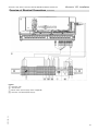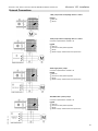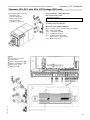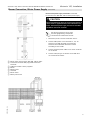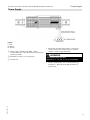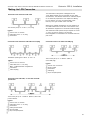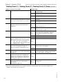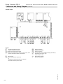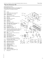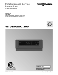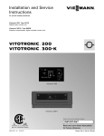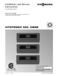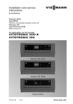
1
Installation and Service Instructions for use by heating contractor Vitotronic 100, Type GC1B Digital boiler control unit For use with Boiler models VD2A, VD2 and CT3 Vitotronic 300-K, Type MW1B Weather-compensated digital cascade control unit VITOTRONIC 100 VITOTRONIC 300-K r r Vitotronic 100 Vitotronic 300-K Product may not be exactly as shown IMPORTANT Certified as a component part for Viessmann boilers 5793 309 - 04 02/2015 Read and save these instructions for future reference. Please file in Service Binder General Vitotronic 100, GC1B / Vitotronic 300-K, MW1B Installation and Service Safety, Installation and Warranty Requirements Please ensure that these instructions are read and understood before commencing installation. Failure to comply with the instructions listed below and details printed in this manual can cause product/property damage, severe personal injury, and/or loss of life. Ensure all requirements below are understood and fulfilled (including detailed information found in manual subsections). Product documentation Read all applicable documentation before commencing installation. Store documentation near boiler in a readily accessible location for reference in the future by service personnel. WARNING Installers must follow local regulations with respect to installation of carbon monoxide detectors. Follow the Viessmann maintenance schedule of the boiler contained in this manual. For a listing of applicable literature, please see section entitled “Important Regulatory and Safety Requirements”. Operating and Service Documentation Licensed professional heating contractor The installation, adjustment, service and maintenance of this equipment must be performed by a licensed professional heating contractor. It is recommended that all product documentation such as parts lists, operating and service instructions be handed over to the system user for storage. Documentation is to be stored near boiler in a readily accessible location for reference by service personnel. Please see section entitled “Important Regulatory and Installation Requirements”. Advice to owner Once the installation work is complete, the heating contractor must familiarize the system operator/ ultimate owner with all equipment, as well as safety precautions/requirements, shutdown procedure, and the need for professional service annually before the heating season begin. Warranty Information contained in this and related product documentation must be read and followed. Failure to do so renders the warranty null and void. Product Information Vitotronic 100, Type GC1B For installation in or mounting on Viessmann boilers only. Applicable to the following control units: Order No. 7134555, 7143156, 7511362 from Serial No. 7143000 Order No. 7134555, 7143156, 7511362 from Serial No. 7187101 2 5793 309 - 04 Order No. 7134555, 7143156, 7511362 from Serial No. 7248248 Vitotronic 100, GC1B / Vitotronic 300-K, MW1B Installation and Service Table of Contents Page General Safety, Installation and Warranty Requirements..............2 Product Information....................................................2 Safety For your Safety..........................................................6 About these Instructions..............................................7 Installation Examples Overview of System Examples.....................................8 System Example 1.....................................................9 Multi boiler system: Boiler with Therm-Control..........9 Equipment required..............................................10 Electrical installation scheme................................13 Code required at every Vitotronic 100....................16 Code required at the Vitotronic 300-K....................16 System Example 2...................................................17 Multi boiler system: Boilers with shunt pump for every boiler for return temperature raising........17 Equipment required..............................................18 Electrical installation scheme................................21 Code required at every Vitotronic 100....................24 Code required at the Vitotronic 300-K....................24 System Example 3..................................................25 Multi boiler system: Boilers with boiler circuit pump and 3-way mixing valve return temperature raising.....................................25 Equipment required..............................................26 Electrical installation scheme.................................29 Code required at every Vitotronic 100....................32 Code required at the Vitotronic 300-K....................32 System Example 4...................................................33 Multi boiler system: Vitocrossal and low temperature boilers with Therm-Control, with several heating circuits and one low temperature heating circuit.............................33 Equipment required..............................................34 Electrical installation scheme................................37 Code required at every Vitotronic 100....................40 Code required at the Vitotronic 300-K....................40 5793 309 - 04 System Example 5....................................................41 Multi boiler system: Vitocrossal and low temperature boilers with 3-way mixing valve, with several heating circuits and one low temperature heating circuit...................................41 Equipment required..............................................42 Electrical installation scheme................................45 Code required at every Vitotronic 100....................48 Code required at every Vitotronic 300-K.................48 Control Unit Installation Mounting the Control Unit.........................................49 Fitting the Control Unit Front.....................................50 Opening the Control Unit...........................................51 Vitotronic 100, Installation Overview of Electrical Connections.............................52 Pump Connection Overview.......................................54 Inserting Cables and Applying Strain Relief...................55 Inserting the Boiler Coding Card.................................55 Inserting the LON Communication Module....................56 3 Table of Contents Vitotronic 100, GC1B / Vitotronic 300-K, MW1B Installation and Service Page Adjusting the Fixed High Limit (if required)...................56 Changing the Adjustable High Limit (if required).............57 Connecting Sensors...................................................57 Power Supply...........................................................58 External Connections................................................59 Connecting Actuators................................................60 Connecting the Central Fault Message Facility..............61 Connection of Low Water Cut-off Device 150 ..............61 Connection to Safety Equipment 150 ..........................61 External Burner Blocking 150 .....................................62 Connections to Terminal 151 .....................................62 Vitotronic 100, GC1 with 30% LTP Package (VD2 only).....................................63 External Changeover of Multi Stage/ Modulating Burners........................................................64 Blocking Boiler Externally/ Adding to the Boiler Sequence....................................64 Connection of Combustion Air Device.........................65 Connection of Combustion Air Device on Multiple Boiler Systems...............................................66 Burner Connection, Burner Control Wiring....................67 Burner Connection, Motor Power Supply......................69 Vitotronic 300-K, Installation Overview of Electrical Connections.............................72 Inserting Cables/Leads and Applying Strain Relief.........74 Connecting Pumps....................................................75 Connecting Sensors...................................................76 Power Supply...........................................................77 External Connections................................................78 Connecting Actuators................................................79 Connecting the Central Fault Message Facility..............80 External Demand via Switching Contact......................80 External Demand via 0-10V Input...............................81 External Blocking via Switching Contact......................81 External “Mixing Valve Closed”/“Mixing Valve Open”........82 External Heating Program Changeover.........................82 Making the LON Connection.......................................83 Commissioning Testing the Fixed High Limit - Vitotronic 100...............84 Changing the Language on the Vitotronic 300-K...........84 Setting the Date and Time on the Vitotronic 300-K.......84 Matching the Coding Addresses to the System Version...................................................85 Selecting the Boiler Sequence at the Vitotronic 300-K.......................................................86 Connecting the Control Unit to the LON.......................87 Checking Actuator and Sensors at the Vitotronic 100................................................90 Commissioning Checking Actuator and Sensors at the Vitotronic 300-K.....................................91 Adjusting Heating Curves...........................................92 Service Scans, Vitotronic 100 Calling up Service Level.............................................94 Exiting the Service Level............................................94 Scanning Operating Data...........................................94 Brief Scan...............................................................95 Scanning and Resetting Service Display.......................96 5793 309 - 04 4 Vitotronic 100, Installation Vitotronic 100, GC1B / Vitotronic 300-K, MW1B Installation and Service Table of Contents 5793 309 - 04 Page Service Scans, Vitotronic 300-K Calling up Service Menu............................................97 Scanning Operating Data...........................................97 Brief Scan...............................................................98 Scanning and Resetting Service Display.......................98 Troubleshooting, Vitotronic 100 Fault Display............................................................99 Fault Codes............................................................100 Troubleshooting, Vitotronic 300-K Fault Display..........................................................103 Fault Codes............................................................104 Function Description Boiler Temperature Control-Vitotronic 100.................108 Boiler Temperature Control-Vitotronic 300-K..............109 Cascade Control of the Vitotronic 300-K...................110 Heating Circuit Control Unit of the Vitotronic 300-K............................................113 DHW Tank Temperature Control of the Vitotronic 300-K...........................................................117 Coding 1, Vitotronic 100 Calling up Coding Level 1........................................119 Group 1 “General”..................................................120 Group 2 “ Boiler”....................................................120 Coding 2, Vitotronic 100 Calling up Coding Level 2........................................122 Group 1 “General”..................................................123 Group 2 “ Boiler”....................................................125 Coding 1, Vitotronic 300-K Calling up Coding Level 1........................................128 “General” Group.....................................................129 “Cascade” Group...................................................130 “DHW” Group………….…………………………………..…130 “Solar” Group.........................................................131 “Heating Circuit 1”, “Heating Circuit 2”, “Heating Circuit 3” Group........................................132 Coding 2, Vitotronic 300-K Calling up Coding Level 2........................................135 “General” Group.....................................................136 “Cascade” Group...................................................141 “DHW” Group........................................................142 “Solar” Group.........................................................144 “Heating Circuit 1”, “Heating Circuit 2”, “Heating Circuit 3” Group........................................147 Wiring, Vitotronic 100 Connection and Wiring Diagram................................151 Wiring, Vitotronic 300-K Connection and Wiring Diagram................................154 Components Sensors.................................................................158 Mixing Valve Motor Kit............................................159 Extension EA1 Accessory (optional).........................160 Parts Lists Parts List Vitotronic 100.........................................161 Parts List Vitotronic 300-K......................................162 Specification Specification Vitotronic 100....................................163 Specification Vitotronic 300-K.................................163 5 Safety Vitotronic 100, GC1B / Vitotronic 300-K, MW1B Installation and Service For your Safety Follow these safety instructions closely to avoid the risk of injury and damage to property. H Operation Before operating the boiler, make sure you fully understand its method of operation. Your heating contractor should always perform the initial start-up and explain the system. Any warranty is null and void if these instructions are not followed. H Flue gas smell - Deactivate heating equipment. - Open windows and doors. - Inform your heating contractor. H Working on the equipment All personnel working on the equipment or the heating system must have the proper qualifications and hold all necessary licenses. Ensure main power to equipment, heating system, and all external controls has been deactivated. Close main gas supply valve. Take precautions in all instances to avoid accidental activation of power during service work. H Dangerous conditions - Deactivate main power immediately. - Close gas supply valve. H Maintenance and cleaning Regular inspection and service by a qualified heating contractor is important to the performance of the boiler. Neglected maintenance impacts on warranty; regular inspection ensures clean, environmentally friendly and efficient operation. We recommend a maintenance contract with a qualified heating contractor. H Technical Data Manual - Installation Instruction and Service Instructions - Operating Instructions and User’s Information Manual Additional applicable literature: - Accessory manuals 6 If you smell gas H Don’t smoke! Don’t use naked flames or cause sparks (e.g. by switching lights or electrical appliances on and off) H Open windows and doors H Close the gas shut-off valve H Inform your heating engineers/service contractors from outside the building H Observe the safety regulations of your gas supply company (see gas meter) and those of your heating engineers (see start-up or instruction report). In emergencies H Immediately switch off the power supply, e.g. at the separate fuse or power supply disconnect switch (unless there is a smell of gas). H Close the shut-off valves in the oil pipes or close the gas shut-off valve, whichever applicable. H Use suitable extinguishers in the event of fire. Installation of additional components The installation of additional components which have not been tested together with the boiler can adversely affect the function and performance of the boiler. Our warranty does not cover and we accept no liability for damage attributable to the installation of such components. Boiler room conditions H Do not use a room in which the air is polluted by halogenated hydro-carbons (e.g. as contained in aerosols, paints, solvents and cleaning agents) H Do not use a room subject to high levels of dust H Do not use a room subject to permanently high humidity H The room should be frost-protected H Max. ambient temperature 95°F (35°C). H Provide good ventilation and do not close or obstruct vents (if installed). 5793 309 - 04 CAUTION Vitotronic 100, GC1B / Vitotronic 300-K, MW1B Installation and Service Safety About these Instructions Take note of all symbols and notations intended to draw attention to potential hazards or important product information. These include “WARNING”, “CAUTION”, and “IMPORTANT”. See below. WARNING Warnings draw your attention to the presence of potential hazards or important product information. Indicates an imminently hazardous situation which, if not avoided, could result in loss of life, serious injury or substantial product/property damage. CAUTION Cautions draw your attention to the presence of potential hazards or important product information. Indicates an imminently hazardous situation which, if not avoided, may result in minor injury or product/ property damage. IMPORTANT Helpful hints for installation, operation or maintenance which pertain to the product. This symbol indicates that additional, pertinent information is to be found. 5793 309 - 04 This symbol indicates that other instructions must be referenced. 7 Installation Examples Vitotronic 100, GC1B / Vitotronic 300-K, MW1B Installation and Service Overview of System Examples Designations in the System Example Boiler Characteristics Page 1 Vitorond Therm-Control 9 2 Vitorond Shunt pump for every boiler for return temperature raising 17 3 Vitorond Boiler circuit pump and 3-way mixing valve for raising the return temperature 25 4 Vitocrossal, Vitorond Low temperature boilers with Therm-Control, with several heating circuits and one low temperature heating circuit 33 5 Vitocrossal, Vitorond Low temperature boilers with 3-way mixing valve, with several heating circuits and one low temperature heating circuit 41 H These system examples are merely recommendations and must therefore be checked on site for completeness and function. H Connect three-phase consumers via additional contactors. H With the Vitotronic 300-K, the communication module is integrated. 8 5793 309 - 04 H With the Vitotronic 100, the communication module is an accessory. Vitotronic 100, GC1B / Vitotronic 300-K, MW1B Installation and Service Installation Examples System Example 1 Multi boiler system: Boiler with Therm-Control 5793 309 - 04 Note: This scheme is a basic example without shut-off devices or safety equipment. This does not replace the need for local engineering. 9 Installation Examples System Example 1 Vitotronic 100, GC1B / Vitotronic 300-K, MW1B Installation and Service (continued) Equipment required Pos. Description 1 Boiler I 2 Therm-Control temperature sensor 3 Boiler water temperature sensor KTS 4 Motorized isolation valve 5 Supply temperature sensor, common heating flow VTS as - contact temperature sensor (standard delivery for Vitotronic 300-K) or - immersion temperature sensor 6 Outside temperature sensor ATS 7 Vitotronic 300-K 8 Vitotronic 100 9 Boiler II qP Therm-Control temperature sensor qQ Boiler water temperature sensor KTS qW Motorized isolation valve qE Vitotronic 100 qR DHW tank qT DHW tank temperature sensor STS qZ DHW pump qU DHW recirculation pump qI Heating circuit 2 wP Heating circuit pump M2 Extension kit for one heating circuit with mixing valve: qO Supply temperature sensor M2 as contact temperature sensor and wQ Mixing valve motor M2 or qO Supply temperature sensor M2 as - contact temperature sensor or 10 wQ Mixing valve motor for flanged mixing valve M2 wW Heating circuit 3 wR Heating circuit pump M3 Extension kit for one heating circuit with mixing valve: wE Supply temperature sensor M3 as contact temperature sensor and wT Mixing valve motor M3 5793 309 - 04 - immersion temperature sensor and Vitotronic 100, GC1B / Vitotronic 300-K, MW1B Installation and Service System Example 1 Installation Examples (continued) Equipment required Pos. wE Description or Supply temperature sensor M3 as - contact temperature sensor or - immersion temperature sensor and wT Mixing valve motor for flanged mixing valve M3 wZ Heating circuit 1 at the Vitotronic 200-H eP wI Heating circuit pump M1 Extension kit for one heating circuit with mixing valve: wU Supply temperature sensor M1 as contact temperature sensor and wO Mixing valve motor M1 or wU Supply temperature sensor M1 as - contact temperature sensor or - immersion temperature sensor and wO Mixing valve motor for flanged mixing valve M1 eP Vitotronic 200-H and LON communication module (accessory) and LON connecting cable (accessory) eQ Outside temperature sensor ATS Boiler accessories eR Connection to safety equipment aBÖ (see page 61) eT Minimum pressure limiter SDB eZ Maximum pressure limiter SDB eU Water level limiter (low water indicator) WB eI Central fault message system S eO Flue gas temperature sensor AGS External hook-ups zR - External changeover of stepped/modulating burners zI - External boiler blocking zO - Start boiler externally as the last one in the boiler sequence 5793 309 - 04 System accessories eE Vitotrol 200A or Vitotrol 300A eI Central fault message system S rP ON/OFF switch 11 Installation Examples System Example 1 Vitotronic 100, GC1B / Vitotronic 300-K, MW1B Installation and Service (continued) Equipment required Pos. Description tP KM BUS distributor, for several KM BUS subscibers zP Extension EA1 zQ 1 switching output (floating changeover contact): - Switching a feed pump to a substation - Signalling reduced mode for a heating circuit zW 1 analogue input (0 – 10V): - Specifying the set system supply temperature zE 3 digital inputs: - External heating program changeover, separately adjustable for heating circuits 1 to 3 - External demand - External blocking with fault message - Fault message input - Short term operation of DHW recirculation pump 12 zT - External blocking/mixing valve closed zZ - External demand zU - External heating program changeover/mixing valve open uP LON communication module (standard delivery Vitotronic 300-K) for communication with the following components: Vitotronic boiler and heating circuit control units Vitocom 100 LAN 1 5793 309 - 04 External hook-ups Vitotronic 100, GC1B / Vitotronic 300-K, MW1B Installation and Service System Example 1 Installation Examples (continued) 5793 309 - 04 Electrical installation scheme 13 Installation Examples 14 (continued) 5793 309 - 04 System Example 1 Vitotronic 100, GC1B / Vitotronic 300-K, MW1B Installation and Service Vitotronic 100, GC1B / Vitotronic 300-K, MW1B Installation and Service 5793 309 - 04 System Example 1 Installation Examples (continued) 15 Installation Examples System Example 1 Vitotronic 100, GC1B / Vitotronic 300-K, MW1B Installation and Service (continued) Code required at every Vitotronic 100 01:2 Group Function 2 “Boiler” Multi boiler system with cascade control via LON Boiler number at the Vitotronic: 07:2 2 “Boiler” Boiler 2 07:3 2 “Boiler” Boiler 3 07:4 2 “Boiler” Boiler 4 4A:1 1 “General” Therm-Control temperature sensor connection at plug aJA; automatic recognition. LON participant number at the Vitotronic: 77:2 1 “General” Vitotronic 300-K with two Vitotronic 100 Boiler 2 77:3 1 “General” Boiler 3 77:4 1 “General” Boiler 4 Code required at the Vitotronic 300-K Group 16 System scheme without system circuit (heating circuit A1) 35:1 “Cascade” Vitotronic 300-K with one Vitotronic 100 35:2 “Cascade” Vitotronic 300-K with two Vitotronic 100 35:3 “Cascade” Vitotronic 300-K with three Vitotronic 100 35:4 “Cascade” Vitotronic 300-K with four Vitotronic 100 5793 309 - 04 00:3, 00:4, 00:7, 00:8 Function Vitotronic 100, GC1B / Vitotronic 300-K, MW1B Installation and Service Installation Examples System Example 2 Multi boiler system: Boilers with shunt pump for every boiler for return temperature raising 5793 309 - 04 Note: This scheme is a basic example without shut-off devices or safety equipment. This does not replace the need for local engineering. 17 Installation Examples System Example 2 Vitotronic 100, GC1B / Vitotronic 300-K, MW1B Installation and Service (continued) Equipment required Pos. Description 1 Boiler I 2 Boiler water temperature sensor KTS 3 Vitotronic 100 4 Vitotronic 300-K 5 Outside temperature sensor ATS 6 Supply temperature sensor, common heating flow VTS as - contact temperature sensor (standard delivery for Vitotronic 300-K) or - immersion temperature sensor 7 Motorized isolation valve 8 Temperature sensor T2 as - contact temperature sensor or - immersion temperature sensor 9 Shunt pump qP Temperature sensor T1 as - contact temperature sensor or - immersion temperature sensor qQ Boiler II qW Boiler water temperature sensor KTS qE Vitotronic 100 qR Motorized isolation valve qT Temperature sensor T2 as - contact temperature sensor or - immersion temperature sensor qZ Shunt pump qU Temperature sensor T1 as - contact temperature sensor or 18 qI DHW tank qO DHW tank temperature sensor STS wP DHW recirculation pump wQ DHW pump wW Heating circuit 2 wR Heating circuit pump M2 Extension kit for one heating circuit with mixing valve: 5793 309 - 04 - immersion temperature sensor Vitotronic 100, GC1B / Vitotronic 300-K, MW1B Installation and Service System Example 2 Installation Examples (continued) Equipment required Pos. Description wE Supply temperature sensor M2 as contact temperature sensor and wT Mixing valve motor M2 or wE Supply temperature sensor M2 as - contact temperature sensor or - immersion temperature sensor and wT Mixing valve motor for flanged mixing valve M2 wZ Heating circuit 3 wI Heating circuit pump M3 Extension kit for one heating circuit with mixing valve: wU Supply temperature sensor M3 as contact temperature sensor and wO Mixing valve motor M3 or wU Supply temperature sensor M3 as - contact temperature sensor or - immersion temperature sensor and wO Mixing valve motor for flanged mixing valve M3 eP Heating circuit 1 at the Vitotronic 200-H eR eW Heating circuit pump M1 Extension kit for one heating circuit with mixing valve: eQ Supply temperature sensor M1 as contact temperature sensor and eE Mixing valve motor M1 or eQ Supply temperature sensor M1 as - contact temperature sensor or 5793 309 - 04 - immersion temperature sensor and eE Mixing valve motor for flanged mixing valve M1 eR Vitotronic 200-H and LON communication module (accessory) and LON connecting cable (accessory) 19 Installation Examples System Example 2 Vitotronic 100, GC1B / Vitotronic 300-K, MW1B Installation and Service (continued) Equipment required Pos. eT Description Outside temperature sensor ATS Boiler accessories eZ Connection to safety equipment aBÖ (see page 61) eU Minimum pressure limiter SDB eI Maximum pressure limiter SDB eO Water level limiter (low water indicator) WB rQ Flue gas temperature sensor AGS rO Central fault message system S External hook-ups zR - External changeover of stepped/modulating burners zI - External boiler blocking zO - Start boiler externally as the last one in the boiler sequence System accessories rP ON/OFF switch rO Central fault message system S tP Vitotrol 200A or Vitotrol 300A tE KM BUS distributor, for several KM BUS participants zP Extension EA1 zQ 1 switching output (floating changeover contact): - Switching a feed pump to a substation - Signalling reduced mode for a heating circuit zW 1 analogue input (0 – 10V): - Specifying the set system supply temperature zE 3 digital inputs: - External heating program changeover, separately adjustable for heating circuits 1 to 3 - External demand - External blocking with fault message - Fault message input - Short term operation of DHW recirculation pump 20 zT - External blocking/mixing valve closed zZ - External demand zU - External heating program changeover/mixing valve open uP LON communication module (standard delivery Vitotronic 300-K) for communication with the following components: Vitotronic boiler and heating circuit control units 5793 309 - 04 External hook-ups Vitotronic 100, GC1B / Vitotronic 300-K, MW1B Installation and Service System Example 2 Installation Examples (continued) 5793 309 - 04 Electrical installation scheme 21 Installation Examples 22 (continued) 5793 309 - 04 System Example 2 Vitotronic 100, GC1B / Vitotronic 300-K, MW1B Installation and Service Vitotronic 100, GC1B / Vitotronic 300-K, MW1B Installation and Service 5793 309 - 04 System Example 2 Installation Examples (continued) 23 Installation Examples System Example 2 Vitotronic 100, GC1B / Vitotronic 300-K, MW1B Installation and Service (continued) Code required at every Vitotronic 100 01:2 Group Function 2 “Boiler” Multi boiler system with cascade control via LON Boiler number at the Vitotronic: 07:2 2 “Boiler” Boiler 2 07:3 2 “Boiler” Boiler 3 07:4 2 “Boiler” Boiler 4 4A:1 1 “General” Temperature sensor T1 connection at plug aJA; automatic recognition. 4b:1 1 “General” Temperature sensor T2 connection at plug aJB; automatic recognition. 77:2 1 “General” Boiler 2 77:3 1 “General” Boiler 3 77:4 1 “General” Boiler 4 LON participant number at the Vitotronic: Code required at the Vitotronic 300-K Group 24 Function System scheme without system circuit (heating circuit A1) 35:1 “Cascade” Vitotronic 300-K with one Vitotronic 100 35:2 “Cascade” Vitotronic 300-K with two Vitotronic 100 35:3 “Cascade” Vitotronic 300-K with three Vitotronic 100 35:4 “Cascade” Vitotronic 300-K with four Vitotronic 100 5793 309 - 04 00:3, 00:4, 00:7, 00:8 Vitotronic 100, GC1B / Vitotronic 300-K, MW1B Installation and Service System Example 3 Installation Examples (continued) Multi boiler system: Boilers with boiler circuit pump and 3-way mixing valve for return temperature raising 5793 309 - 04 Note: This scheme is a basic example without shut-off devices or safety equipment. This does not replace the need for local engineering. 25 Installation Examples System Example 3 Vitotronic 100, GC1B / Vitotronic 300-K, MW1B Installation and Service (continued) Equipment required Pos. Description 1 Boiler I 2 Boiler water temperature sensor KTS 3 Vitotronic 100 4 Vitotronic 300-K 5 Outside temperature sensor ATS 6 Supply temperature sensor, common heating flow VTS as - contact temperature sensor (standard delivery for Vitotronic 300-K) or - immersion temperature sensor 7 3-way mixing valve 8 Temperature sensor T1 as - contact temperature sensor or - immersion temperature sensor 9 Boiler circuit pump qP Boiler II qQ Boiler water temperature sensor KTS qW Vitotronic 100 qE 3-way mixing valve qR Temperature sensor T1 as - contact temperature sensor or - immersion temperature sensor qT Boiler circuit pump qZ DHW tank qU DHW tank temperature sensor STS qI DHW recirculation pump qO DHW pump wP Heating circuit 2 wW Heating circuit pump M2 Extension kit for one heating circuit with mixing valve M2: wQ - Supply temperature sensor M2 as contact temperature sensor and wE - Mixing valve motor or wQ Supply temperature sensor M2 as - contact temperature sensor or 26 5793 309 - 04 - immersion temperature sensor Vitotronic 100, GC1B / Vitotronic 300-K, MW1B Installation and Service System Example 3 Installation Examples (continued) Equipment required Pos. Description wE Mixing valve motor M2 for flanged mixing valve M2 wR Heating circuit 3 wZ Heating circuit pump M3 Extension kit for one heating circuit with mixing valve M3: wT Supply temperature sensor M3 as contact temperature sensor and wU - Mixing valve motor or wT Supply temperature sensor M3 as - contact temperature sensor or - immersion temperature sensor wU Mixing valve motor M2 for flanged mixing valve M3 wI Heating circuit 1 at the Vitotronic 200-H eW eP Heating circuit pump M1 Extension kit for one heating circuit with mixing valve: wO Supply temperature sensor M1 as contact temperature sensor and eQ Mixing valve motor M1 or wO Supply temperature sensor M1 as - contact temperature sensor or - immersion temperature sensor and eQ Mixing valve motor for flanged mixing valve M1 eW Vitotronic 200-H and LON communication module (accessory) and LON connecting cable (accessory) eE Outside temperature sensor ATS 5793 309 - 04 Boiler accessories eR Connection to safety equipment aBÖ (see page 61) eT Minimum pressure limiter SDB eZ Maximum pressure limiter SDB eU Water level limiter (low water indicator) WB eO Flue gas temperature sensor AGS rU Central fault message system S External hook-ups zR - External changeover of stepped/modulating burners 27 Installation Examples System Example 3 Vitotronic 100, GC1B / Vitotronic 300-K, MW1B Installation and Service (continued) Equipment required Pos. Description zI - External boiler blocking zO - Start boiler externally as the last one in the boiler sequence System accessories rP ON/OFF switch rU Central fault message system S rI Vitotrol 200A or Vitotrol 300A tE KM BUS distributor, for several KM BUS participants zP Extension EA1 zQ 1 switching output (floating changeover contact): - Switching a feed pump to a substation - Signalling reduced mode for a heating circuit zW 1 analog input (0 – 10V): - Specifying the set system supply temperature zE 3 digital inputs: - External heating program changeover, separately adjustable for heating circuits 1 to 3 - External demand - External blocking with fault message - Fault message input - Short term operation of DHW recirculation pump 28 zT - External blocking/mixing valve closed zZ - External demand zU - External heating program changeover/mixing valve open uP LON communication module (standard delivery Vitotronic 300-K) for communication with the following components: Vitotronic boiler and heating circuit control units 5793 309 - 04 External hook-ups Vitotronic 100, GC1B / Vitotronic 300-K, MW1B Installation and Service System Example 3 Installation Examples (continued) 5793 309 - 04 Electrical installation scheme 29 Installation Examples 30 (continued) 5793 309 - 04 System Example 3 Vitotronic 100, GC1B / Vitotronic 300-K, MW1B Installation and Service Vitotronic 100, GC1B / Vitotronic 300-K, MW1B Installation and Service 5793 309 - 04 System Example 3 Installation Examples (continued) 31 Installation Examples System Example 3 Vitotronic 100, GC1B / Vitotronic 300-K, MW1B Installation and Service (continued) Code required at every Vitotronic 100 Group Function 01:2 2 “Boiler” Multi boiler system with cascade control via LON 07:2 2 “Boiler” Boiler 2 07:3 2 “Boiler” Boiler 3 07:4 2 “Boiler” Boiler 4 0C:1 2 “Boiler” Constant return temperature control 4A:1 1 “General” Temperature sensor T1 connection at plug aJA; automatic recognition. 4d:2 1 “General” Boiler circuit pump connection at plug sL 77:2 1 “General” Boiler 2 77:3 1 “General” Boiler 3 77:4 1 “General” Boiler 4 Boiler number at the Vitotronic: LON participant number at the Vitotronic: Code required at the Vitotronic 300-K Group 32 System scheme without system circuit (heating circuit A1) 35:1 “Cascade” Vitotronic 300-K with one Vitotronic 100 35:2 “Cascade” Vitotronic 300-K with two Vitotronic 100 35:3 “Cascade” Vitotronic 300-K with three Vitotronic 100 35:4 “Cascade” Vitotronic 300-K with four Vitotronic 100 5793 309 - 04 00:3, 00:4, 00:7, 00:8 Function Vitotronic 100, GC1B / Vitotronic 300-K, MW1B Installation and Service System Example 4 Installation Examples (continued) Multi boiler system: Vitocrossal and low temperature boilers with Therm-Control, with several heating circuits and one low temperature heating circuit 5793 309 - 04 Note: This scheme is a basic example without shut-off devices or safety equipment. This does not replace the need for local engineering. 33 Installation Examples System Example 4 Vitotronic 100, GC1B / Vitotronic 300-K, MW1B Installation and Service (continued) Equipment required Pos. Description 1 Boiler I 2 Boiler water temperature sensor KTS 3 Supply temperature sensor, common heating flow VTS as - contact temperature sensor (standard delivery for Vitotronic 300-K) or - immersion temperature sensor 4 Outside temperature sensor ATS 5 Vitotronic 300-K 6 Vitotronic 100 7 Neutralizing system 8 Boiler II 9 Vitotronic 100 qP Therm-Control temperature sensor qQ Motorized isolation valve qW Boiler water temperature sensor KTS qE DHW tank qR DHW tank temperature sensor STS qT DHW pump qZ DHW recirculation pump qU Heating circuit 2 qO Heating circuit pump M2 Extension kit for one heating circuit with mixing valve: qI Supply temperature sensor M2 as contact temperature sensor and wP Mixing valve motor M2 or qI Supply temperature sensor M2 as - contact temperature sensor or 34 wP Mixing valve motor for flanged mixing valve M2 wQ Heating circuit 3 wE Heating circuit pump M3 Extension kit for one heating circuit with mixing valve: wW Supply temperature sensor M3 and wR Mixing valve motor M3 or 5793 309 - 04 - immersion temperature sensor and Vitotronic 100, GC1B / Vitotronic 300-K, MW1B Installation and Service System Example 4 Installation Examples (continued) Equipment required Pos. wW Description Supply temperature sensor M3 as - contact temperature sensor or - immersion temperature sensor and wR Mixing valve motor for flanged mixing valve M3 wT Heating circuit 1 (low temperature heating circuit) at the Vitotronic 200-H wO wU Heating circuit pump M1 Extension kit for one heating circuit with mixing valve: wZ Supply temperature sensor M1 as contact temperature sensor and wI Mixing valve motor M1 or wZ Supply temperature sensor M1 as - contact temperature sensor or - immersion temperature sensor and wI Mixing valve motor for flanged mixing valve M1 wO Vitotronic 200-H and LON communication module for pos. 29 and LON connecting cable eP Outside temperature sensor ATS Boiler accessories eW Connection to safety equipment aBÖ (see page 61) eE Maximum pressure limiter SDB eR Minimum pressure limiter SDB eT Water level limiter (low water indicator) WB rR Central fault message system S eU Flue gas temperature sensor AGS External hook-ups zR - External changeover of stepped/modulating burners zI - External boiler blocking zO - Start boiler externally as the last one in the boiler sequence 5793 309 - 04 System accessories eQ Vitotrol 200A or Vitotrol 300A rP ON/OFF switch rR Central fault message system S 35 Installation Examples System Example 4 Vitotronic 100, GC1B / Vitotronic 300-K, MW1B Installation and Service (continued) Equipment required Pos. Description tE KM BUS distributor, for several KM BUS participants zP Extension EA1 zQ 1 switching output (floating changeover contact): - Switching a feed pump to a substation - Signalling reduced mode for a heating circuit zW 1 analog input (0 – 10V): - Specifying the set system supply temperature zE 3 digital inputs: - External heating program changeover, separately adjustable for heating circuits 1 to 3 - External demand - External blocking with fault message - Fault message input 36 zT - External blocking/mixing valve closed zZ - External demand zU - External heating program changeover/mixing valve open uP LON communication module (standard delivery Vitotronic 300-K) for communication with the following components: Vitotronic boiler and heating circuit control units 5793 309 - 04 - Short term operation of DHW recirculation pump External hook-ups Vitotronic 100, GC1B / Vitotronic 300-K, MW1B Installation and Service System Example 4 Installation Examples (continued) 5793 309 - 04 Electrical installation scheme 37 Installation Examples 38 (continued) 5793 309 - 04 System Example 4 Vitotronic 100, GC1B / Vitotronic 300-K, MW1B Installation and Service Vitotronic 100, GC1B / Vitotronic 300-K, MW1B Installation and Service 5793 309 - 04 System Example 4 Installation Examples (continued) 39 Installation Examples System Example 4 Vitotronic 100, GC1B / Vitotronic 300-K, MW1B Installation and Service (continued) Code required at every Vitotronic 100 Group Function 01:2 2 “Boiler” Multi boiler system with cascade control via LON 07:2 Boiler number at the Vitotronic: 2 “Boiler” Boiler 2 07:3 2 “Boiler” Boiler 3 07:4 2 “Boiler” Boiler 4 4A:1 Only with the Vitotronic 100 of the low temperature boiler: 1 “General” 0d:0 Therm-Control temperature sensor connection at plug aJA; automatic recognition. Only with the Vitotronic 100 of the Vitocrossal: 2 “Boiler” Without Therm-Control temperature sensor 77:2 LON participant number at the Vitotronic: 1 “General” Boiler 2 77:3 1 “General” Boiler 3 77:4 1 “General” Boiler 4 Code required at the Vitotronic 300-K Group 40 System scheme without system circuit (heating circuit A1) 35:1 “Cascade” Vitotronic 300-K with one Vitotronic 100 35:2 “Cascade” Vitotronic 300-K with two Vitotronic 100 35:3 “Cascade” Vitotronic 300-K with three Vitotronic 100 35:4 “Cascade” Vitotronic 300-K with four Vitotronic 100 39:1 to 39:4 “Cascade” Permanent lead boiler System with one condensing boiler and several low temperature boilers: Program the condensing boiler as the permanent lead boiler 3A:1 to 3A:4 “Cascade” Permanent last boiler System with one low temperature boiler and several condensing boilers: Program the low temperature boiler to always be the last boiler. 3C:1 “Cascade” Conventional strategy 1 5793 309 - 04 00:3, 00:4, 00:7, 00:8 Function Vitotronic 100, GC1B / Vitotronic 300-K, MW1B Installation and Service Installation Examples System Example 5 Multi boiler system: Vitocrossal and low temperature boilers with 3-way mixing valve, with several heating circuits and one low temperature heating circuit 5793 309 - 04 Note: This scheme is a basic example without shut-off devices or safety equipment. This does not replace the need for local engineering. 41 Installation Examples System Example 5 Vitotronic 100, GC1B / Vitotronic 300-K, MW1B Installation and Service (continued) Equipment required Pos. Description 1 Boiler I 2 Boiler water temperature sensor KTS 3 Supply temperature sensor, common heating flow VTS as - contact temperature sensor (standard delivery for Vitotronic 300-K) or - immersion temperature sensor 4 Outside temperature sensor ATS 5 Vitotronic 300-K 6 Vitotronic 100 7 Neutralizing system 8 Boiler II 9 Vitotronic 100 qP Temperature sensor T1 as - contact temperature sensor or - immersion temperature sensor qQ 3-way mixing valve qW Boiler circuit pump qE Boiler water temperature sensor KTS qR DHW tank qT DHW tank temperature sensor STS qZ DHW pump qU DHW recirculation pump qI Heating circuit 2 wP Heating circuit pump M2 Extension kit for one heating circuit with mixing valve: qO Supply temperature sensor M2 as contact temperature sensor and wQ Mixing valve motor M2 or qO Supply temperature sensor M2 as - contact temperature sensor or 42 wQ Mixing valve motor for flanged mixing valve M2 wW Heating circuit 3 wR Heating circuit pump M3 Extension kit for one heating circuit with mixing valve: 5793 309 - 04 - immersion temperature sensor and Vitotronic 100, GC1B / Vitotronic 300-K, MW1B Installation and Service System Example 5 Installation Examples (continued) Pos. Description wE Supply temperature sensor M3 as contact temperature sensor and wT Mixing valve motor M3 or wE Supply temperature sensor M3 as - contact temperature sensor or - immersion temperature sensor and wT Mixing valve motor for flanged mixing valve M3 wZ Heating circuit 1 (low temperature heating circuit) at the Vitotronic 200-H eP wI Heating circuit pump M1 wU Supply temperature sensor M1 as contact temperature sensor and wO Mixing valve motor M1 or wU Supply temperature sensor M1 as - contact temperature sensor or - immersion temperature sensor and wO Mixing valve motor for flanged mixing valve M1 eP Vitotronic 200-H and LON communication module and LON connecting cable eQ Outside temperature sensor ATS 5793 309 - 04 Boiler accessories eE Connection to safety equipment aBÖ (see page 61) eR Maximum pressure limiter SDB eT Minimum pressure limiter SDB eZ Water level limiter (low water indicator) WB rT Central fault message system S eI Flue gas temperature sensor AGS External hook-ups zR External changeover of stepped/modulating burners zI External boiler blocking zO Start boiler externally as the last one in the boiler sequence 43 Installation Examples System Example 5 Vitotronic 100, GC1B / Vitotronic 300-K, MW1B Installation and Service (continued) Pos. Description System accessories eW Vitotrol 200A or Vitotrol 300A rP ON/OFF switch rT Central fault message system S tE KM BUS distributor, for several KM BUS participants zP Extension EA1 zQ 1 switching output (floating changeover contact): - Switching a feed pump to a substation - Signalling reduced mode for a heating circuit zW 1 analog input (0 – 10V): - Specifying the set system supply temperature zE 3 digital inputs: - External heating program changeover, separately adjustable for heating circuits 1 to 3 - External demand - External blocking with fault message - Fault message input 44 zT - External blocking/mixing valve closed zZ - External demand zU - External heating program changeover/mixing valve open uP LON communication module (standard delivery Vitotronic 300-K) for communication with the following components: Vitotronic boiler and heating circuit control units 5793 309 - 04 - Short term operation of DHW recirculation pump External hook-ups Vitotronic 100, GC1B / Vitotronic 300-K, MW1B Installation and Service System Example 5 Installation Examples (continued) 5793 309 - 04 Electrical installation scheme 45 Installation Examples 46 (continued) 5793 309 - 04 System Example 5 Vitotronic 100, GC1B / Vitotronic 300-K, MW1B Installation and Service Vitotronic 100, GC1B / Vitotronic 300-K, MW1B Installation and Service 5793 309 - 04 System Example 5 Installation Examples (continued) 47 Installation Examples System Example 5 Vitotronic 100, GC1B / Vitotronic 300-K, MW1B Installation and Service (continued) Code required at every Vitotronic 100 Group 01:2 07:2 Function Multi boiler system with cascade control via LON Boiler number at the Vitotronic 2 “Boiler” Boiler 2 07:3 2 “Boiler” Boiler 3 07:4 2 “Boiler” Boiler 4 0C:1 Only with the Vitotronic 100 of the low temperature boiler: 2 “Boiler” Constant return temperature control 4A:1 1 “General” Temperature sensor T1 connection at plug aJA; automatic recognition. 4d:2 1 “General” Boiler circuit pump connection at plug sL Only with the Vitotronic 100 of the Vitocrossal: 0d:0 2 “Boiler” Without Therm-Control temperature sensor LON participant number at the Vitotronic: 77:2 1 “General” Boiler 2 77:3 1 “General” Boiler 3 77:4 1 “General” Boiler 4 Code required at the Vitotronic 300-K Group 48 Function System scheme without system circuit (heating circuit A1) 35:1 “Cascade” Vitotronic 300-K with one Vitotronic 100 35:2 “Cascade” Vitotronic 300-K with two Vitotronic 100 35:3 “Cascade” Vitotronic 300-K with three Vitotronic 100 35:4 “Cascade” Vitotronic 300-K with four Vitotronic 100 39:1 to 39:4 “Cascade” Permanent lead boiler System with one condensing boiler and several low temperature boilers: Program the condensing boiler as the permanent lead boiler. 3A:1 to 3A:4 “Cascade” Permanent last boiler System with one low temperature boiler and several condensing boilers: Program the low temperature boiler to always be the last boiler. 3b:3 “Cascade” Stand-alone control, boiler connected in series with supply temperature sensor 5793 309 - 04 00:3, 00:4, 00:7, 00:8 Vitotronic 100, GC1B / Vitotronic 300-K, MW1B Installation and Service Mounting the Control Unit Control Unit Installation 1. Fasten the metal back plate to the mounting surface with four fasteners. 2. Install the junction box to the back plate. 3. Fasten the junction box to the back plate with two fasteners. 4. Install the control rear section to the junction box housing. Hook the control to the back plate tabs and pivot downwards. 5. Fasten the control rear section to the junction box with two fasteners. 5793 309 - 04 Note: The Vitotronic 100 GC1B boiler control must be mounted directly to the boiler (see boiler installation instructions).The 300-K MW1B can be mounted remotely. 49 Control Unit Installation Vitotronic 100, GC1B / Vitotronic 300-K, MW1B Installation and Service Fitting the Control Unit Front 1. Snap on the control cover to the control housing. 2. Snap on the interface cover to the control cover. 3. Release the stay bar and lock in position. 4. Insert the plug from the programming unit to the control. Note: Route the ribbon cable through retainer A. 5. Return the stay bar to the control cover and lock in position. 6. Close the control cover. 7. Secure the control cover to the front housing with supplied fasteners. 8. Install the junction box cover and support with a supplied screws. Legend A Cable retaining tab 50 5793 309 - 04 Note: Route the ribbon cable through retainer A. Vitotronic 100, GC1B / Vitotronic 300-K, MW1B Installation and Service Control Unit Installation 5793 309 - 04 Opening the Control Unit 1. Remove the junction box cover screws and remove the cover. 2. Remove the front housing screws. 3. Swing up the front part of the control housing. 4. Position the stay bar so that it supports the front housing. 51 Vitotronic 100, Installation Vitotronic 100, GC1B / Vitotronic 300-K, MW1B Installation and Service Overview of Electrical Connections Note: When connecting plugs aVD and aVH, bundle the individual cores of the cables close to the terminals. This prevents the cores from shifting into the neighboring voltage area. Main PCB low voltage § Boiler water temperature sensor aG Flue gas temperature sensor (accessory) aJA Therm-Control temperature sensor or Return temperature sensor T1 (standard delivery with Vitorond, accessory for Vitocrossal) aJB Return temperature sensor T2 (accessory) aVD aVG aVH External hook-up KM BUS participant (accessory) External hook-up Main PCB 120V~ sÖA1 sL fÖ fA gÖ gSA1 lÖ aBÖ aBA aBH Switching output pump/shunt pump Boiler pump Power supply Burner (call for heat) Central fault message Isolation valve Burner stage 2/mod. External connections, e.g. supplementary safety equipment (low water cut-off) Safety chain, floating Power supply connection for accessories 52 5793 309 - 04 Prior to making any connections ensure that the control control and junction box have been installed as per the boiler Installation Instructions. Vitotronic 100, GC1B / Vitotronic 300-K, MW1B Installation and Service Overview of Electrical Connections Vitotronic 100, Installation (continued) 5793 309 - 04 Legend A Vitotronic 100 B Junction box C Burner motor power supply (refer to page 69) fÖ Vitotronic 100 GC1B power supply 53 Vitotronic 100, Installation Vitotronic 100, GC1B / Vitotronic 300-K, MW1B Installation and Service Pump Connection Overview Rated current: 2A~ * Maximum output 6FLA shared between all 120V outputs. 54 Pumps 120V Available pump connections sÖM1/A1 Switching contact/shunt pump sL Boiler pump sA No Function 5793 309 - 04 Legend A 120V pump output B To the Vitotronic control unit C Junction box Vitotronic 100, GC1B / Vitotronic 300-K, MW1B Installation and Service Vitotronic 100, Installation Inserting Cables and Applying Strain Relief H Control unit fitted on the boiler: Route cables from below through the front panel of the boiler into the wiring chamber of the control unit. H Control unit fitted to the side of the boiler: Route cables from below out of the cable channel into the control unit. Legend A Cables with moulded strain relief B On-site cables; strip up to 4 in. (100 mm) insulation Inserting the Boiler Coding Card 5793 309 - 04 Only use the boiler coding card supplied with the boiler (see table in chapter “Components”). Insert the boiler coding card into slot “X7”, through the recess in the cover. Boiler Coding card Identification Spare parts no. Vitocrossal 300, CT3 1040 7841118 7841118 Vitorond 200, VD2, VD2A 1020 7841111 7841111 55 Vitotronic 100, Installation Vitotronic 100, GC1B / Vitotronic 300-K, MW1B Installation and Service Inserting the LON Communication Module Making the LON connection, see page 83. B A Legend A LON communication module (accessory) B Vitotronic 100 GC1B Adjusting the Fixed High Limit (if required) When adjusting the fixed high limit to lower temperatures, it can not be adjusted back to a higher temperature. Also when adjusting the fixed high limit, the adjustable high limit and the electronic temperature limiter must also be adjusted (see chart below). WARNING Disconnect power to the control and burner! 1. Unclip the fuse box and swing upwards. 56 Non-condensing boiler (VD2/VD2A) °F (°C) Condensing boiler (CT3) °F (°C) Factory set at; Adjustable to; Factory set at; Fixed high limit 230°F (110°C) 210°F (99°C) 248°F (120°C) 210°F (99°C) Adjustable high limit 212°F (100°C) 203°F (95°C) 230°F (110°C) 203°F (95°C) Coding address for the electronic maximum temperature limit of Vitotronic 100; set coding address 06 (see boiler coding section) to the temperature as shown or less 200°F (93°C) 188°F (87°C) 223°F (106°C) 188°F (87°C) 5793 309 - 04 2. Turn the slotted screw on the rear of the fixed high limit until the slot points to the desired temperature. 3. Re-fit the fuse box. Vitotronic 100, GC1B / Vitotronic 300-K, MW1B Installation and Service Vitotronic 100, Installation Changing the Adjustable High Limit (if required) Note: Excessive DHW temperatures can damage the DHW tank. If the system is operated in conjunction with a DHW tank, ensure that the maximum permissible water temperature is not exceeded. If necessary, install suitable safety equipment for this purpose. 1. Remove rotary selector A. 2. Using a pair of pointed pliers, break the restraining tab B or C out of the stop dial as shown. 3. Install rotary selector A. Turn rotary selector A to the required temperature. The slot should line up to the selected temperature. Note: The control comes factory preset to a maximum allowable adjustable high limit of 100°C. Once the adjustable high limit is changed the temperature can be reduced to a minimum of 75°C. Legend A Rotary selector B Break required tab or C Break required tab 5793 309 - 04 Connecting Sensors Legend Main PCB low voltage § Boiler water temperature sensor aG Flue gas temperature sensor (accessory) aJA Therm-Control temperature sensor or Return temperature sensor T1 (standard delivery for Vitorond accessory for Vitocrossal) aJB Return temperature sensor T2 (accessory) 57 Vitotronic 100, Installation Vitotronic 100, GC1B / Vitotronic 300-K, MW1B Installation and Service Power Supply Legend L: Line N: Neutral G: Ground A Power supply 120VAC, 1PH, 60Hz, provide disconnect means and overcurrent protection as per local codes B Terminals N, G and 11 (in junction box) C Junction box 1. Ensure that the main power supply to the control contains overcurrent protection with a minimum rating of 12A and 2-pole disconnect. WARNING The control must be grounded. Ensure that “L”, “N” and “G” are not interchanged. 58 5793 309 - 04 2. Connect power supply wire to the connection fÖ terminals 11, N and G on the DIN rail inside the junction box. Vitotronic 100, GC1B / Vitotronic 300-K, MW1B Installation and Service Vitotronic 100, Installation External Connections 120V pumps with an amperage draw of <2FLA Legend A Din rail B Pump 120V pumps with an amperage draw of >2FLA Contactor specification 120VAC 1A Legend A Din rail B Contactor/relay (field supplied) C Pump D Power supply w/disconnect and protection 240V single phase pumps Contactor specification 120VAC 1A Legend A Din rail B Contactor/relay (field supplied) C Pump D Power supply w/disconnect and protection 208/460/575V 3 phase pumps 5793 309 - 04 Contactor specification 120VAC 1A Legend A Din rail B Contactor/relay (field supplied) C Pump D Power supply w/disconnect and protection 59 Vitotronic 100, Installation Vitotronic 100, GC1B / Vitotronic 300-K, MW1B Installation and Service Connecting Actuators Legend A 24V Mixing Valve Adaptor B DIN Rail (in junction box) C 24V Valve Actuator D Valve Legend A 120V Mixing Valve Adaptor B DIN Rail (in connection enclosure) C 120V Valve Actuator D Valve 120V Valve Adaptor Rated voltage: Rated current: 1. Disconnect power to control. 24V Valve Adaptor Rated voltage: Rated current: 120VAC max. 0.1 FLA 2. Install 120V or 24V valve adaptor on DIN rail inside connection enclosure. Refer to the valve adaptor Installation Instructions. 24VAC max. 0.15 FLA 3. Insert the plug gS into socket gS on the Vitotronic control. 4. Fasten cable with tie. 60 5. Connect black wire of the adaptor to terminals 8,9 or 10 on the Din rail. 6. Connect valve actuator wires to the adaptor terminals 5793 309 - 04 gS A1 / M1: for boiler protection (via 100% low temperature protection package) or motorized isolation valve. Operating time: 5 to 199 sec. selected via coding address “40”. Vitotronic 100, Installation Vitotronic 100, GC1B / Vitotronic 300-K, MW1B Installation and Service Connecting the Central Fault Message Facility Rated voltage Rated current 120V~ max. 2A~ Connection of Low Water Cut-off Device 150 1. Remove jumper between terminals 12 and 15. 2. Make connection as shown in diagram. CAUTION The diagram shown is only a simplified conceptual drawing of a typical low water cut off (LWCO) device. Refer to the manual specific to the device for interconnection details. aBH Power supply for accessories. aBÖ Connection for external equipment. A Low water cut-off (typical) Connections to Safety Equipment 150 5793 309 - 04 1. Connect the external safety equipment in series. Legend A DIN rail B Low water cutoff C Other safety controls 61 Vitotronic 100, Installation Vitotronic 100, GC1B / Vitotronic 300-K, MW1B Installation and Service External Burner Blocking 150 Note: ‘Live’ contacts lead to short circuits or phase failure. The external connection must be floating. Remove jumper from DIN terminals 16 and 17. Note: Connect only safety shutdown equipment (dry contact), e.g. a combustion air device adaptor, to these terminals. Opening this contact leads to a burner control shutdown. Note: The heating system has no frost protection during blocking. The boiler is not held at the lower boiler water temperature. Connections to Terminal aBA External shut-off 1. Remove jumper between terminals 19 and 20. 2. Connect dry contact. Controlled switch-off takes place when the contact is opened. WARNING 62 5793 309 - 04 The terminals should be used for safety switch-off purposes only (e.g. through a high limit thermostat). During switch-off, there is no frost protection of the heating system and the boiler is not kept at the minimum boiler water temperature. Vitotronic 100, GC1B / Vitotronic 300-K, MW1B Installation and Service Vitotronic 100, Installation Vitotronic 100, GC1 with 30% LTP Package (VD2 only) 30% LTP Package consists of: - 1 circulation pump - 1 cast iron flange set - 2 full port ball valves - 1 flow check valve - 1 17B sensor (strap -on) Each pump output: 120V single phase Max. pump current: 2 FLA IMPORTANT Pump current larger than 2 FLA will require a contactor or isolation relay (see page 59). Mandatory Coding Address Changes 0C:5 - Constant control of return water temperature. 0d:2 - Switching contact 4A:1 - 17A Sensor installed 4b:1 - 17B Sensor installed 4C:2 - Connections at plug 20A1 Therm control switch contact 4d:2 - Boiler circuit pump 5793 309 - 04 Legend A Vitotronic 100 control B Junction box C Return temperature 2 aJB D Return temperature 1 aJA E Shunt pump sÖA1 F Boiler pump sL 63 Vitotronic 100, Installation Vitotronic 100, GC1B / Vitotronic 300-K, MW1B Installation and Service External Changeover of Multi Stage/Modulating Burners Connection at plug aVH. Note: ‘Live’ contacts lead to short circuits or phase failure. The external connection must be floating. Contact open: modulating mode Contact closed: two stage mode Code Set code “02:2” in group 2 “Boiler”. Legend A External changeover (floating contact) Note: When scanning the burner version, the address for modulation appears even after an external changeover (no rewriting). Blocking Boiler Externally/Adding to the Boiler Sequence Connection at plug aVD. Note: ‘Live’ contacts lead to short circuits or phase failure. The external connection must be floating. Contact A: H Contact closed: The boiler is removed from the boiler sequence. The isolation valve or the 3- way mixing valve are closed for constant return temperature control. Shunt pump or boiler circuit pump are switched off. The heat demand has to be met by the other boilers. Legend A Blocking boiler externally (floating contact) B Start boiler externally as the last one in the boiler sequence (floating contact) Note: If all boilers are blocked or there is no other boiler available for duty, there will be no frost protection for the heating system. H Contact open: The boiler is integrated into the current boiler sequence. Contact B: H Contact closed: The heat demand of the heating system is met by the other boilers. This boiler is started if the output of these boilers is insufficient. 64 5793 309 - 04 H Contact open: The boiler is integrated into the current boiler sequence. Vitotronic 100, GC1B / Vitotronic 300-K, MW1B Installation and Service Vitotronic 100, Installation Connection of Combustion Air Device Legend A Combustion Air Device Adaptor B DIN Rail in connection enclosure Connection of the Combustion Air Device Adaptor 1. Disconnect power to control and burners. 2. Install Combustion Air Device Adaptor, on DIN Rail inside connection enclosure (refer to installation manual of Combustion Air Device Adaptor). 3. Remove jumper between terminals 16 and 17. 4. Make connection as shown in the diagram. IMPORTANT Wire BK2 must be connected to terminal 16 and BK3 to terminal 17 - DO NOT reverse. 5793 309 - 04 For more detail, refer to the combustion air device Installation Instructions. 65 Vitotronic 100, Installation Vitotronic 100, GC1B / Vitotronic 300-K, MW1B Installation and Service Connection of Combustion Air Device on Multiple Boiler Systems If a single combustion air device is required for a multiple boiler system, a Common Combustion Air Interface must be installed. Rated voltage: 120VAC Rating current: max 5 FLA 1. Install Combustion Air Device Adaptor on each boiler. 2. Install Common Combustion Air Device Interface, as per supplied manual. 3. Make connection as shown in the diagram at left. Refer to Installation and Operating Instructions of Common Combustion Air Device Interface for details. 66 5793 309 - 04 Legend A Common Combustion Air Device Interface (wall mount) B Combustion Air Device Adaptorthe boiler control junction box C Interconnecting wiring (field supplied and connected) Vitotronic 100, GC1B / Vitotronic 300-K, MW1B Installation and Service Vitotronic 100, Installation Burner Connection, Burner Control Wiring For burners with plug-in connection The burner cables are included in the standard delivery of the Vitotronic. Connect the burner in accordance with applicable codes. Terminal codes L Phase via fixed high limit to the burner ? Ground connection N Neutral connection to the burner T1,T2 Control circuit S3 Connection for burner fault indicator B4 Connection for burner hours counter 1. Disconnect power to burner and boiler control. 2. Connect plugs fA and plug lÖ to respective counter plugs in boiler control unit. 3. Connect the 7-pole plug fA and the 3-pole plug lÖ to the burner. CAUTION This is a generic connection drawing only! Follow the burner manufacturer’s connection drawings for Viessmann controls. Legend A To boiler control unit B To burner Terminal codes 1,2,3 Control circuit ”2nd stage burner or modulation controller” (via two-point controller with 2-stage operation; via three-point controller with modulating operation) 1 From burner 2 Modulating down 3 Modulating up/2nd stage ON 5793 309 - 04 Colour codes as applicable BK Black BN Brown BU Blue Legend A To plug-in connection in the Vitotronic boiler control junction box B To burner 67 Vitotronic 100, GC1B / Vitotronic 300-K, MW1B Installation and Service Burner Connection, Burner Control Wiring CAUTION This is a generic connection drawing only! Follow the burner manufacturer’s connection drawings for Viessmann controls. (continued) For burner without plug-in connection The burner cables are included in the standard delivery of the Vitotronic. Connect the burner in accordance with applicable codes. Note: Write the terminal numbers or markings on the drawing for future reference. Legend A Vitotronic 100 control B Junction box C Burner fA Burner, 1st stage lÖ Burner, 2nd stage/modulation Refer to burner manufacturer’s instruction on detailed connections for Viessmann controls. 68 5793 309 - 04 Vitotronic 100, Installation Vitotronic 100, GC1B / Vitotronic 300-K, MW1B Installation and Service Vitotronic 100, Installation Burner Connection, Motor Power Supply CAUTION The control must be grounded. Ensure that “L”, “N” and “G” are not interchanged. 1. Ensure that the main power supply to the control contains overcurrent protection with a maximum rating of 15A and 2 pole disconnect. 2. Connect power supply wire to the Connection fÖ terminals 11, N and G on the DIN rail inside the connection enclosure. 5793 309 - 04 Legend A Burner motor power supply 120VAC, 1PH B Connection terminals and plug inside connection enclosure C Cable and conduit- factory supplied D Burner E Motor starter F Burner motor G Connection enclosure on boiler control Supply power must be sufficient to cover both the 12A control plus the required motor amperage. 69 Vitotronic 100, Installation Vitotronic 100, GC1B / Vitotronic 300-K, MW1B Installation and Service Burner Connection, Motor Power Supply Burner motor power supply connection For burners with 240VAC, 1PH power supply and connection in conduit. See burner manual for correct fuse and wire gauge sizing, and specific connections for Viessmann controls. 1. Disconnect power to burner and boiler control. 2. Connect 240VAC power to the terminals 21, 22 and 23 on the DIN rail inside the connection enclosure. Provide fuseable disconnect means according to local codes. 3. Connect supplied power cable to the motor terminals on the burner. 4. Connect cable plug to the socket on the DIN rail in the connection enclosure. 70 5793 309 - 04 Legend A Burner motor power supply 240VAC, 1PH B Connection terminals and plug inside connection enclosure C Cable and conduit- factory supplied D Burner E Motor starter F Burner motor G Connection enclosure on boiler control Vitotronic 100, GC1B / Vitotronic 300-K, MW1B Installation and Service Burner Connection, Motor Power Supply Vitotronic 100, Installation (continued) Burner motor power supply connection (continued) For burners with 3PH 208, 460 or 575V power supply. CAUTION During commissioning check for correct motor rotation. If motor rotates in opposite direction than indicated on the burner, disconnect power supply and reverse wires BK1 and BK2 on the burner terminals. See burner manual for correct fuse and wire gauge sizing, and specific connections for Viessmann controls. 1. Disconnect power to burner and boiler control. 2. Connect 3PH power to the terminals 21, 22, 23 and 24 on the DIN rail inside the connection enclosure. Provide fusible disconnect means according to local codes. 3. Connect supplied power cable to the motor terminals on the burner. 4. Connect cable plug to the socket on the DIN rail in the connection enclosure. 5793 309 - 04 A Burner motor power supply 3PH 208, 460 or 575V B Connection terminals and plug inside connection enclosure C Cable and conduit- factory supplied D Burner E Motor starter F Overload G Burner motor H Boiler junction box 71 Vitotronic 300-K, Installation Vitotronic 100, GC1B / Vitotronic 300-K, MW1B Installation and Service Overview of Electrical Connections Note: When connecting plugs aVD and aVH, bundle the individual wires of the cables close to the terminals. This ensures that, should there be an error, for example when detaching a wire, the wires cannot drift into the adjacent voltage area. Extension for heating circuits 2 and 3 with mixing valve Main PCB 120V~ ? M2/M3 Supply temperature sensor sÖ M2/M3 Heating circuit pump gS M2/M3 Mixing valve motor sÖA1 Heating circuit pump or Primary pump, primary store system sA Circulation pump for DHW tank heating (optional accessory, not used) ! §/? %A %B aJB aVD aVG aVH LON 72 Outside temperature sensor Supply temperature sensor, common heating flow DHW tank temperature sensor DHW tank temperature sensor 2 for primary store system (optional accessory, not used) Return temperature sensor T2 (optional accessory, not used) or Temperature sensor primary store system (optional accessory, not used) External hook-up KM BUS participant External hook-up LON BUS, connecting cable for data exchange with the Vitotronic 100 GC1B, Vitotronic 200-H HK1B, Vitocom LAN 1 sK sL fÖ gÖ gSA1 aBH DHW recirculation pump (on site) Shunt pump or distribution pump (on site) Power supply Central fault message Motor for 3-way mixing valve, primary store system or Motor for 3-way mixing valve, return temperature control Power supply connection for mixing valve module circuit M2 and M3 Note: When inserting cables and applying strain relief see page 74. 5793 309 - 04 Main PCB low voltage Vitotronic 100, GC1B / Vitotronic 300-K, MW1B Installation and Service Overview of Electrical Connections Vitotronic 300-K, Installation (continued) 5793 309 - 04 Legend A Vitotronic 300-K B Junction box fÖ Vitotronic 300-K power supply connection 73 Vitotronic 300-K, Installation Vitotronic 100, GC1B / Vitotronic 300-K, MW1B Installation and Service Inserting Cables/Leads and Applying Strain Relief Run the cables from the connection enclosure into the control unit. Apply strain relief to cables. Cables with moulded strain relief clamp: Connect cable and strain relief clamp. OR Fasten cable to the cable lead with cable tie. 74 5793 309 - 04 Legend A Cables with moulded strain relief B On-site cables; strip up to 4 in. (100 mm) insulation. Vitotronic 100, GC1B / Vitotronic 300-K, MW1B Installation and Service Vitotronic 300-K, Installation Connecting Pumps Legend A 120V Pump outputs B To the Vitotronic control unit C Junction box 5793 309 - 04 Rated current: 2A~ * Maximum pump output 6FLA shared between all 120V outputs. Pumps 120V Available pump connections sÖA1/M1 sÖM2 sÖM3 sA sK sL High temperature circuit pump Heating circuit M2 pump Heating circuit M3 pump DHW pump DHW recirculation pump System pump 75 Vitotronic 300-K, Installation Vitotronic 100, GC1B / Vitotronic 300-K, MW1B Installation and Service Connecting Sensors Installation point for outside temperature sensor H North or north-western wall, 6.6 to 8.2 ft. (2 to 2.5 m) above ground level; in multi storey buildings, in the upper half of the second floor H Not above windows, doors or ventilation outlets H Not immediately below balconies or gutters H Never render over Outside temperature sensor connection Two wire communication cable 16 AWG (maximum length 95 ft. (30 m) 76 5793 309 - 04 Legend ! Outside temperature sensor §/? Common supply temperature sensor %A DHW tank temperature sensor 1 %B DHW tank temperature sensor 2 for primary store system (optional accessory, not used) aJB Return temperature sensor T2 or Temperature sensor primary store system (optional accessory, not used) Vitotronic 100, GC1B / Vitotronic 300-K, MW1B Installation and Service Power Supply Power Supply Legend L: Line N: Neutral G: Ground A Power supply 120VAC, 1PH, 60Hz, 12FLA provide disconnect means and overcurrent protection as per local codes B Terminals N, G and 11 (in junction box) C Junction box 1. Ensure that the main power supply to the control contains overcurrent protection with a minimum rating of 12A and 2-pole disconnect. WARNING The control must be grounded. Ensure that “L”, “N” and “G” are not interchanged. 5793 309 - 04 2. Connect power supply wire to the connection fÖ terminals 11, N and G on the DIN rail inside the junction box. 77 Vitotronic 300-K, Installation Vitotronic 100, GC1B / Vitotronic 300-K, MW1B Installation and Service External Connections 120V pumps with an amperage draw of <2FLA Legend A Din rail B Pump 120V pumps with an amperage draw of >2FLA Contactor specification 120VAC 1A Legend A Din rail B Contactor/relay (field supplied) C Pump D Power supply w/disconnect and protection 240V single phase pumps Contactor specification 120VAC 1A Legend A Din rail B Contactor/relay (field supplied) C Pump D Power supply w/disconnect and protection 78 5793 309 - 04 208/460/575V 3 phase pumps Contactor specification 120VAC 1A Legend A Din rail B Contactor/relay (field supplied) C Pump D Power supply w/disconnect and protection Vitotronic 100, GC1B / Vitotronic 300-K, MW1B Installation and Service Vitotronic 300-K, Installation Connecting Actuators Legend A 24V Mixing Valve Adaptor B DIN Rail (in junction box) C 24V Valve Actuator D Valve Legend A 120V Mixing Valve Adaptor B DIN Rail (in junction box) C 24V Valve Actuator D Valve 120V Valve Adaptor Rated voltage: Rated current: 1. Disconnect power to control. 120VAC max. 0.1 FLA 2. Install 120V or 24V valve adaptor on DIN rail inside connection enclosure. 3. Insert the plug gS into socket gS on the control. 4. Fasten cable with tie. 24V Valve Adaptor Rated voltage: Rated current: 24VAC max. 0.15 FLA 5. Connect black wire of the adaptor to terminals 8,9 or 10 on the Din rail. 6. Connect valve actuator wires to the adaptor terminals Operating time: 5 to 199 sec. selected via coding address “40”. Available connections Refer to the mixing valve adaptor Installation Instructions for additional information. gS A1 Motor for 3-way mixing valve, primary store system gS M2 For heating circuit 2 gS M3 For heating circuit 3 5793 309 - 04 Rated voltage: Rated current Max.: Motor runtime for 3-way mixing valve: 120V~ 0.1A~ 10 to 255 sec, adjustable via coding addresses “6A” in the”DHW”group, “C3” in the HC2 group and “C3” in the HC3 group. 79 Vitotronic 300-K, Installation Vitotronic 100, GC1B / Vitotronic 300-K, MW1B Installation and Service Connecting the Central Fault Message Facility Rated voltage Rated current 120V~ max. 2A~ External Demand Via Switching Contact Connection Note: ‘Live’ contacts lead to short circuits or phase failure. The external connection must be floating. Connection options: H Plug aVH H Extension EA1 (accessory, see page 160) Legend A Floating contact B Plug aVH of the control unit With the contact closed, the boiler burners are started subject to load. They heat to the set supply temperature selected in coding address “9B” in the “General” group. The temperature is limited by this set value and the electronic maximum supply temperature limit (coding address “37” in the “Cascade” group). Legend A Floating contact B Extension EA1 80 Plug aVH Extension EA1 No code required. Set “5D”, “5E” or “5F” in the “General” group to 2. 5793 309 - 04 Codes Vitotronic 100, GC1B / Vitotronic 300-K, MW1B Installation and Service Vitotronic 300-K, Installation External Demand via 0–10V Input Connection at input 0 – 10V at extension EA1 (see page 160). 0 - 1V no default set supply temperature 1V set value 50°F (10°C) 10V set value 212°F (100°C) Observe coding address “1E” in the “General” group. Optional Temperature range from 86 to 248°F (30 to 120°C): 0 - 1V no default set supply temperature 1V 86°F (30°C) 10V 248°F (120°C) External Blocking via Switching Contact Connection options: H Plug aVD H Extension EA1 (accessory, see page 160) Connection Note: ‘Live’ contacts lead to short circuits or phase failure. The external connection must be floating. Legend A Floating contact B Plug aVD of the control unit With the contact closed, the burners of all boilers will be subject to a control shutdown. Any connected shunt or distribution pump is stopped. Shut-off devices are closed. Note: The heating system has no frost protection during blocking. The boilers are not held at the lower boiler water temperature. Legend A Floating contact B Extension EA1 5793 309 - 04 Codes Plug aVD Extension EA1 Set coding address “99” in the “General” group, which the input should influence. Set “5D”, “5E” or “5F” in the “General” group to 3 or 4. 81 Vitotronic 300-K, Installation Vitotronic 100, GC1B / Vitotronic 300-K, MW1B Installation and Service External “Mixing Valve Closed”/”Mixing Valve Open” Connection at plug aVD. Note: ‘Live’ contacts lead to short circuits or phase failure. The external connection must be floating. Codes External “Mixing valve open” External “Mixing valve closed” Via coding address “9A” in the “General” group, this function is assigned to the heating circuits. Via coding address “99” in the “General” group, this function is assigned to the heating circuits. Legend A External “Mixing valve open” (floating contact) B External “Mixing valve closed” (floating contact) External Heating Program Changeover Connection Note: ‘Live’ contacts lead to short circuits or phase failure. The external connection must be floating. Connection options: H Plug aVD H Extension EA1 (accessory, see page 160) Codes Legend A Floating contact B Plug aVD of the control unit Plug aVD Extension EA1 This function is assigned to the heating circuits via coding address “91” in the “General” group. Set “5D”, “5E” or “5F” in the “General” group to 1. This function can be assigned to the heating circuits via coding address “D8” in the “Heating circuit...” group. Legend A Floating contact B Extension EA1 (Contact open) 9 or w or 82 w Central heating OFF/ DHW OFF Central heating OFF/DHW ON Central heating ON/DHW ON Coding D5:0 (factory set condition) D5:1 Changed heating program (Contact closed) Permanent operation with reduced room temperature/DHW OFF Constant operation with standard room temperature, DHW in accordance with coding address “64” 5793 309 - 04 Preselected heating program Vitotronic 100, GC1B / Vitotronic 300-K, MW1B Installation and Service Vitotronic 300-K, Installation Making the LON Connection Connection with Viessmann LON cable The line may be up to ≤ 23 ft. (7 m) long The Viessmann LON system is designed for the “Line” BUS topology with a terminator at both ends (accessories). The transfer distances for LON are subject to the electrical properties of the respective cabling. For this reason, only use the stated cable types. Use only one type of cable within the LON. Observe the cabling requirements for the operation of the LON interface FTT 10-A (see www.echelon.com). Legend A Control unit or Vitocom B LON cable, 23 ft. (7 m) long C Terminator All Viessmann equipment is connected via RJ45 plugs. The Viessmann LON system always requires the cores “1” and “2” and the screen. The cores are interchangeable. The installation is therefore safe from pole errors. Connection with Viessmann LON cable and coupling Connection with on-site cable and LON plug ≤ 3000 ft. Installation spacing 23 to 69 ft. (7 to 21 m) Legend A Control unit or Vitocom B LON cable, 23 ft. (7 m) long Max. 3 cables between 2 appliances C Terminator D LON coupling The line may be up to ≤ 3000 ft. (900 m) (with LON plug) Legend A Control unit or Vitocom B On-site cable C Terminator D LON plug E Up to 99 participants Connection with LON cable, on-site cable and LON junction box 5793 309 - 04 ≤ 3000 ft. The line may be up to ≤ 3000 ft. (900 m) (with LON junction boxes) Legend A Control unit or Vitocom B LON cable, 23 ft. (7 m) long C Terminator D LON junction boxes E On-site cable F Up to 99 participants 83 Commissioning Vitotronic 100, GC1B / Vitotronic 300-K, MW1B Installation and Service Testing the Fixed High Limit -Vitotronic 100 The minimum circulation volume should be 10% of the circulation volume at rated load. Reduce the heat consumption as far as possible. 1. Hold down the “TEST” key until the burner has shut down: Thermostat is bridged. The fixed high limit must shut down the burner at the latest when the safety temperature has been reached. 2. Release the “TEST” key. 3. Wait until the boiler water temperature has dropped approx. 15 to 20 K below the selected safety temperature. 4. Reset the fixed high limit by pressing reset button. Operating instructions Changing the Language on the Vitotronic 300-K At the commissioning stage, the display is in German (default setting). Extended menu: 1. 2. “Einstellungen” (Settings) 3. “Sprache” (Language) Deutsch DE (German) 4. Set the required language with Setting the Date and Time on the Vitotronic 300-K During commissioning, or after prolonged time out of use, the time and date need to be reset. Extended menu: 84 2. “Settings” 3. “Time / Date” 4. Set current time and date. 5793 309 - 04 1. Vitotronic 100, GC1B / Vitotronic 300-K, MW1B Installation and Service Commissioning Matching the Coding Addresses to the System Version Vitotronic 100 Check all addresses in Code 1 and adjust if required. Check the following coding address and adjust accordingly in Code 2: “0C” “0D” “4C” Group 2 “Boiler” 2 “Boiler” 1 “General” Function Return temperature control Therm-Control “4D” 1 “General” Function plug sL “4E” 1 “General” “98” “9C” 1 “General” 1 “General” Function plug gS Viessmann system number Monitoring LON participants Function plug sÖ Matching the control unit to a two-stage burner Matching coding addresses according to the burner used Address Meaning Setting 03:... Fuel Gas operation: 0 (factory set condition) Oil operation: 1 (irreversible) 08:... Units and tens of the maximum Example: Max. burner output: burner output 225 kW – select: 25 09:... 0A:... Hundreds of the maximum burner output Ratio of output base load to maximum burner output in percent Note: Values up to and including 199 kW can be entered directly. Example: Max. burner output: 225 kW – select: 2 Example: Output burner stage 1 135 kW Max. burner output: 225 kW (135 kW : 225 kW) · 100% = 60% Matching the control unit to a modulating burner Note: The burner must be fully adjusted. To achieve a wide modulating range, set the minimum output as low as possible (take the chimney and flue system into account). Matching coding addresses according to the burner used Address Meaning Setting 03:... Fuel Gas operation: 0 (factory set condition) Oil operation: 1 (irreversible) 08:... Units and tens of the maximum Example: Max. burner output: burner output 225 kW – select: 25 09:... 5793 309 - 04 15:... Hundreds of the maximum burner output Modulation range runtime 0A:... Ratio of output base load to maximum burner output in percent 05:... Ratio of partial output at b of the servomotor runtime to maximum burner output in percent Note: Values up to and including 199 kW can be entered directly. Example: Max. burner output: 225 kW – select: 2 Calculate runtime (s) of servomotor between base load and max. burner output Example: Output burner stage 1 135 kW Max. burner output: 225 kW (135 kW : 225 kW) · 100% = 60% Example: Partial output 171 kW Max. burner output: 225 kW (171 kW : 225 kW) · 100% = 76% 85 Commissioning Vitotronic 100, GC1B / Vitotronic 300-K, MW1B Installation and Service Matching the Coding Addresses to the System Version (continued) Vitotronic 300-K Check all addresses in Code 1 and adjust if required. Check the following coding addresses and adjust accordingly in Code 2: Group Function “39” “Cascade” “3A” “Cascade” Permanent last boiler Permanent lead boiler “4C” “General” Function plug sÖ “4D” “General” Function plug sL “4E” “General” Function plug gS “55” “DHW” DHW tank temperature control function “7A” “General” Central control “98” “General” Viessmann system number “9C” “General” Monitoring LON participants Selecting the Boiler Sequence at the Vitotronic 300-K Subject to the set codes in the “Cascade” group and internal control calculations, the control unit offers various boiler sequences. Coding addresses that influence the boiler sequence: “38” Changing the lead boiler and the boiler sequence “39” Permanent lead boiler “3A” Permanent last boiler “41” to “44” ECO thresholds H Via the ECO threshold, every boiler can be blocked or enabled subject to the outside temperature. H If the boiler is required to achieve the set supply temperature in the case of enabled boilers failing, the ECO threshold is disabled. H At least the lead boiler remains active if all boilers in a system are blocked by the ECO threshold. Press 2. “Boiler sequence” 3. Select the required boiler sequence and confirm with OK. . 5793 309 - 04 86 1. Vitotronic 100, GC1B / Vitotronic 300-K, MW1B Installation and Service Commissioning Connecting the Control Unit to the LON Example of a multi boiler system Legend A Vitotronic 100 B Vitotronic 100 C Vitotronic 300-K D Vitotronic 200-H E Vitocom F LON system G Terminal end resistor H The LON communication module must be fitted into every Vitotronic 100 (see page 56). Note: The communication module is integrated in the Vitotronic 300-K. H Vitotronic 200-H: The LON communication module (accessory) must be fitted. Installation and service instructions, Vitotronic 200-H H Within one LON, the same participant number must not be allocated twice. H Within one LON, the system number (coding address “98” in the “General” group) must always be the same. H Only one Vitotronic may be programmed as fault manager. 5793 309 - 04 H The data transfer via the LON system can take several minutes. 87 Commissioning Vitotronic 100, GC1B / Vitotronic 300-K, MW1B Installation and Service A B Multi boiler system. Set code “01:2” in group 2 “Boiler”. Multi boiler system. Set code “01:2” in group 2 “Boiler”. -- -- -- Boiler number 1. Code “07:1” in group 2 “Boiler”. Boiler number 2. Set code “07:2” in group 2 “Boiler”. -- -- -- With LON communication module Code “76:1” in group 1 “General”; automatic recognition. With LON communication module Code “76:1” in group 1 “General”; automatic recognition. -- C -- D With LON communication module Code “76:1” in the “General” group; automatic recognition. Number of connected boilers. Set codes “35:1” to “35:4” in the “Cascade”group. E With LON communication module Code “76:1” in the “General” group; automatic recognition. -- -- -- Participant no. 1. Code “77:1” in group 1 “General”. Participant no. 2. Set code “77:2” in group 1 “General”. Participant no. 5. Set code “77:5” in the “General” group. Participant no. 10. Set code “77:10” in the “General” group. Participant no. 99. Control unit is not fault manager. Code “79:0” in group 1 “General”. Control unit is not fault manager. Code “79:0” in group 1 “General”. Control unit is fault manager. Set code “79:1” in the “General” group. Control unit is not fault manager. Set code “79:0” in the “General” group. Device is fault manager. -- -- Control unit transmits the time. Code “7B:1” in the “General” group. The control unit receives the time. Set code “81:3” in the “General” group. Device receives the time. -- -- Control unit transmits outside temperature. Set code “97:2” in the “General” group. Control unit receives the outside temperature. Set code “97:1” in the “General” group. -- LON participant remote monitoring. Code “9C:20” in the “General” group. LON participant remote monitoring. Code “9C:20” in the “General” group. -- LON participant remote monitoring. Code “9C:20” in group 1 “General”. 88 (continued) LON participant remote monitoring. Code “9C:20” in group 1 “General”. 5793 309 - 04 Connecting the Control Unit to the LON Commissioning Vitotronic 100, GC1B / Vitotronic 300-K, MW1B Installation and Service Connecting the Control Unit to the LON (continued) Carrying out a LON participant check at the Vitotronic 300-K Communication with the system devices connected to the fault manager is tested by means of a participant check. Preconditions: H The control unit must be programmed as fault manager (code “79:1”). H The LON participant no. must be programmed in all control units (coding address “77”). The LON participant list in the fault manager must be up to date. Carrying out the participant check: 1. Press OK and 2. “Service functions” 3. “Participant check” 4. Select participant (e.g. participant 10). The participant check for the selected participant is initiated. H Successfully tested participants are designated with “OK”. H Unsuccessfully tested participants are designated with “Not OK”. simultaneously for approx. 4 sec. Note: To carry out a new participant check, create a new participant list with “Delete list?” (participant list is updated). 5793 309 - 04 Note: H Vitotronic 100: During the participant check, the display for the relevant participant flashes for approx. 1 min. H Vitotronic 200-H: During the participant check, the display for the relevant participant shows the participant no. and “Wink” for approx. 1 min. 89 Commissioning Vitotronic 100, GC1B / Vitotronic 300-K, MW1B Installation and Service Checking Actuators and Sensors at the Vitotronic 100 Carrying out a relay test 1. Press OK and simultaneously for approx. 4 sec. flashes on the display. 2. With select “ 3. Select required actuator (output) (see following table). with The display shows the number for the activated actuator and “ON”. “ and confirm with OK. The following actuators (relay outputs) can be controlled subject to the system equipment level: Display Explanation 0 All actuators have been switched off. 1 Burner “ON” or burner stage 1 “ON” or modulation controller ramps up (modulating burner). 2 Burner stages 1 and 2 “ON” or modulation controller neutral (modulating burner). 3 Modulation controller ramps down (modulating burner). 5 Output sÖ “ON”. 6 Output sL “ON”. 7 Output gS “Open”. 8 Output gS “Neutral”. 9 Output gS “Closed”. 11 Output central fault message gÖ “ON”. Note: During burner operation, the connected pumps are started. Checking sensors Actual temperatures can be scanned in the “i” menu. 90 5793 309 - 04 Refer to the Operating Instructions Commissioning Vitotronic 100, GC1B / Vitotronic 300-K, MW1B Installation and Service Checking Actuators and Sensors at the Vitotronic 300-K Carrying out a relay test 1. Press OK and 2. “Actuator test” simultaneously for approx. 4 sec. The following relay outputs can be controlled subject to the system equipment level: Display Explanation “All actuators” OFF All actuators have been switched off. “Output 20” ON Output 20 enabled. “Output 52” Open - “Output 52” Neutral - “Output 52” Closed - “DHW tank prim pump” ON Output for circulation pump for DHW tank heating enabled. “DHW circ pump” ON Output for DHW recirculation pump enabled. “Output 29” ON Output 29 enabled. “Central fault mess.” ON - “Htg circ pump HC2” ON Output heating circuit pump enabled (heating circuit with mixing valve M2). “Mixing valve HC2” Open Output “Mixing valve open” enabled (heating circuit with mixing valve M2). “Mixing valve HC2” Closed Output “Mixing valve closed” enabled (heating circuit with mixing valve M2). “Htg circ pump HC3” ON Output heating circuit pump enabled (heating circuit with mixing valve M3). “Mixing valve HC3” Open “Mixing valve open” enabled (heating circuit with mixing valve M3). “Mixing valve HC3” Closed Output “Mixing valve open” enabled (heating circuit with mixing valve M3). “EA1 output 1” ON Contact “P - S” on plug aBJ for extension EA1 closed. “AM1 output 1” ON Output enabled. “AM1 output 2” ON Output enabled. “Solar circuit pump” ON Output for solar circuit pump sF at solar control module, type SM1, enabled. “Solar circ pmp min” ON Output for solar circuit pump sF at solar control module, type SM1, switched to minimum speed. “Solar circ pmp max” ON Output for solar circuit pump sF at solar control module, type SM1, switched to maximum speed. “SM1 output 22” ON Output sS at solar control module, type SM1, enabled. 5793 309 - 04 Checking sensors simultaneously for approx. 4 sec. 1. Press OK and 2. “Diagnosis” 3. Select group (see overview on page 97). 4. Scan actual temperature of the relevant sensor. 91 Commissioning Vitotronic 100, GC1B / Vitotronic 300-K, MW1B Installation and Service Adjusting Heating Curves Boiler water or supply temperature The heating curves illustrate the relationship between the outside temperature and the boiler water or supply temperature. To put it simply: The lower the outside temperature, the higher the boiler water or supply temperature. The room temperature, again, depends on the boiler water or the supply temperature. Settings in the factory set condition: H Slope = 1.4 H Shift = 0 Room set point temperature Outdoor temperature Example of outside temperature 7°F (−14°C) Legend A Underfloor heating system, slope 0.2 to 0.8 B Low temperature heating system, slope 0.8 to 1.6 C Heating systems with a boiler water temperature in excess of 167°F (75°C), slope greater than 1.6 Selecting the set room temperature 230°F (110°C) 79°F (26°C) 68°F (20°C) Individually adjustable for each heating circuit. The heating curve is offset along the axis of the set room temperature. When the heating circuit pump logic function has been enabled, it modifies the starting and stopping characteristics of the heating circuit pump. Standard set room temperature Changing the standard room temperature from 68 to 79°F (20 to 26°C) -4°F (-20°C) Refer to the Operating Instructions 92 5793 309 - 04 Legend A Boiler water temperature or supply temperature B Outside temperature C Set room temperature D Heating circuit pump OFF E Heating circuit pump ON Vitotronic 100, GC1B / Vitotronic 300-K, MW1B Installation and Service Adjusting Heating Curves Commissioning (continued) Reduced set room temperature Changing the reduced room temperature from 37 to 57°F (3 to 14°C) Refer to the Operating Instructions Legend A Boiler water temperature or supply temperature B Outside temperature C Set room temperature D Heating circuit pump OFF E Heating circuit pump ON Changing the slope and shift Individually adjustable for each heating circuit. Boiler water or supply temperature Extended menu: 1. Outside temperature 2. “Heating” 3. Select heating circuit. 4. “Heating curve” 5. “Slope” or “Shift” 6. Select heating curve according to the system requirements. Example: Heating curve setting with slope 1.5: 5793 309 - 04 Legend A Changing the slope B Changing the shift (vertical parallel offset of the heating curve) 93 Service Scans, Vitotronic 100 Vitotronic 100, GC1B / Vitotronic 300-K, MW1B Installation and Service Calling up Service Level 1. Press OK and simultaneously for approx. 4 sec. flashes on the display. 2. Select required function, e.g. relay test. 1. Select 9 with “Serv”. 2. Confirm with OK. “OFF” flashes. 3. Confirm with OK. Exiting the Service Level Note: The system exits the service level automatically after 30 min. Scanning Operating Data Operating data can be scanned in the “ ” menu. 94 5793 309 - 04 Refer to the Operating Instructions Vitotronic 100, GC1B / Vitotronic 300-K, MW1B Installation and Service Service Scans, Vitotronic 100 Brief Scan 1. Press OK and simultaneously for approx. 4 sec. flashes on the display. 2. Confirm with OK. 3. Select required scan. For example, “b” for “Boiler coding card” (see following table). 4. Confirm selected scan with OK. 5793 309 - 04 For explanation of individual scans, see the following table: Brief scan Display 8 8 8 8 0 - System scheme (here 0) Software version Control unit 2 - - Maximum flue gas temperature 3 - - Set boiler water temperature 6 - Number of KM BUS participants Number of LON participants 7 SNVT configuration 0:Auto 1:Tool Software version communication coprocessor Software version LON module 8 - Subnet address/system no. Node address 9 - Burner type Appliance type b - Boiler coding card L Burner: 0: OFF 1: Burner stage 1/ base load 2: Burner stage 2/full load Isolation valve: 0: OFF 1: Preheating 2: Control Closed 3: Control 4: Control Open 5: Open 6: Run-on Output reduction in % 0: OFF E 3 - - - 8 8 Software version Programming unit Software version Plug-in adaptor for external safety equipment 95 Service Scans, Vitotronic 100 Vitotronic 100, GC1B / Vitotronic 300-K, MW1B Installation and Service Scanning and Resetting Service Display After the limits set at coding address “1F”, “21”, “23” in group 2 “Boiler” have been reached, the red fault indicator begins to flash and the display shows: H The specified hours run and . H The specified interval with u and . H The specified max. flue gas temperature and . Acknowledging a service Press OK to acknowledge a service message. Note: An acknowledged service message that was not reset reappears after 7 days. After a service has been carried out (resetting service) Reset code “24:1” to “24:0” in group 2 “Boiler”. 96 5793 309 - 04 Note: The selected service parameters for hours run and time interval restart at 0. Service Scans, Vitotronic 300-K Vitotronic 100, GC1B / Vitotronic 300-K, MW1B Installation and Service Calling up the Service Menu Service menu overview Press OK and simultaneously for approx. 4 sec. Service General Heating circuit 1 HC1 Heating circuit 2 HC2 Heating circuit 3 HC3 Diagnosis Actuator test DHW Solar Brief scan Reset data Coding level 1 Coding level 2 Fault history Participant check Service functions Service PIN Service reset Terminate service? “Coding level 2” is only displayed if this level has been enabled: Press OK and simultaneously for approx. 4 sec. Scanning Operating Data Operating data can be scanned in six areas (see “Diagnosis” in the overview “Service menu”). Operating data on heating circuits with mixing valves and solar can only be scanned if the components are installed in the system. For further information on operating data, see chapter “Brief scan”. Note: “- - -” appears on the display if a sensor that has been scanned is faulty. Calling up operating data 1. Press OK and simultaneously for approx. 4 sec. 2. “Diagnosis” 3. Select required group, e.g. “General”. Resetting operating data 5793 309 - 04 Saved operating data (e.g. hours run) can be reset to 0. The value “Adjusted outside temp” is reset to the actual value. 1. Press OK and 2. “Diagnosis” 3. “Reset data” 4. Select required value or “All details”. simultaneously for approx. 4 sec. 97 Service Scans, Vitotronic 300-K Vitotronic 100, GC1B / Vitotronic 300-K, MW1B Installation and Service Brief Scan In the brief scan, you can scan temperatures, software versions and connected components, for example. 1. 2. 3. 4. Press OK and simultaneously for approx. 4 sec. “Diagnosis” “Brief scan”. Press OK. The display shows 9 lines with 6 fields each. For an explanation of the relevant values in the individual lines, see the following table: Line (brief scan) Field 1 2 3 4 5 6 1: System schemes 01 to 10 Control unit software version Programming unit software version 2: 2 0 0 Appliance identification ZE-ID 3: 0 0 Number of KM BUS participants Software version Solar control module 4: 0 0 0 0 0 0 5: 0 0 0 0 Software version, extension AM1 Software version, extension EA1 6: 0 0 0 0 0 0 7: Subnet address/system number Node address 0 0 8: SNVT config. 0: Auto 1: Tool Software version Neuron Chip Number of LON participants System circuit HC1 Heating circuit HC2 Heating circuit HC3 9: 0 0 0 0 0 0 10: 0 0 0 0 0 0 11: 0 0 Software version, extension for heating 0 Software version, extension for heating 0 Software version Communic. coproc. 0 circuits 2 and 3 with mixing valve circuits 2 and 3 with mixing valve Note: The displays in fields 3 and 5 are the same. Scanning and Resetting Service Display No service interval can be set at the Vitotronic 300-K. In other words, no service display is shown. 98 5793 309 - 04 Note: If a service display appears on the Vitotronic 300-K, MW1B, the display will show “Participant fault” and the participant number. Vitotronic 100, GC1B / Vitotronic 300-K, MW1B Installation and Service Troubleshooting, Vitotronic 100 Fault Display In the event of a fault, the red fault display flashes at the control unit. The 2- digit fault code and flash on the display. Note: If a central fault message facility is connected, this is started. Note: A fault message facility, if connected, will be switched off. If an acknowledged fault is not remedied, the fault message will be re-displayed the following day and the fault message facility restarted. Other current faults can be displayed with . For an explanation of the fault code, see chapter “Fault codes”. Calling up acknowledged fault messages Example: Fault code “d1” burner fault Calling up fault codes from the fault memory (fault history) Press OK for approx. 4 sec. The 10 most recent faults (including those remedied) are saved and can be called up. Faults are sorted by date. simultaneously for approx. 4 sec. 1. Press OK and 2. Select 3. Select fault messages with with and activate fault history with OK. . Acknowledging faults 5793 309 - 04 Press OK; the standard display appears. 99 Troubleshooting, Vitotronic 100 Vitotronic 100, GC1B / Vitotronic 300-K, MW1B Installation and Service Fault Codes System characteristics Cause Measures 0F Control mode. Service “0F” is only displayed in the fault history. Service the appliance. Note: After the service, set code “24:0” in group 2 “Boiler”. 30 The burner is started and stopped via a adjustable high limit. Short circuit, boiler water temperature sensor Check the boiler water temperature sensor (see page 158). 38 The burner is started and stopped via a adjustable high limit. Lead break, boiler water temperature sensor Check the boiler water temperature sensor (see page 158). 60 Boiler with maximum temperature, no output reduction, mixing valve return temperature control “Open”. Short circuit, temperature sensor aJA Check temperature sensor (see page 158). 68 Boiler with maximum temperature, no output reduction, mixing valve return temperature control “Open”. Lead break, temperature sensor aJA Check temperature sensor (see page 158). Without temperature sensor: Set code “4A:0” in group 1 “General”. 70 Shunt pump constantly “ON”. Short circuit, temperature sensor aJB Check temperature sensor (see page 158). 78 Shunt pump constantly “ON”. Lead break, temperature sensor aJB Check temperature sensor (see page 158). Without temperature sensor: Set code “4b:0” in group 1 “General”. A0 Boiler cools down. Fault, safety equipment at “X7” of plug-in adaptor 2 for external safety equipment Check safety equipment and reset if required. A1 Boiler cools down. Fault, safety equipment at “X3” of plug-in adaptor 2 for external safety equipment Check safety equipment and reset if required. A2 Boiler cools down. Fault, safety equipment at “X2” of plug-in adaptor 2 for external safety equipment Check safety equipment and reset if required. 5793 309 - 04 100 Displayed fault code Vitotronic 100, GC1B / Vitotronic 300-K, MW1B Installation and Service 5793 309 - 04 Fault Codes Troubleshooting, Vitotronic 100 (continued) Displayed fault code System characteristics Cause Measures A3 Boiler cools down. Fault, safety equipment at “X1” of plug-in adaptor 2 for external safety equipment Check safety equipment, and reset if required. AA Control mode. Therm-Control configuration fault: Plug aJA not plugged in. Insert plug aJA. For Vitocrossal, code “0d: 0” in group 2 “Boiler” must be selected. AC Control mode. Return temperature control configuration error: Code “0C:1” in group 2 “Boiler” has been set, but plug aJA is not plugged in and/or code “4E:0” in group 1 “General” is not set. Insert plug aJA and check codes. Ad Control mode. Isolation valve configuration error: Code “0C:2”, “0C: 3” or “0C:4” in group 2 “Boiler” is set and code “4E:1” in group 1 “General” is set. With isolation valve: Set code “4E:0” in group 1 “General”. Without isolation valve: Set code “0C:1” in group 2 “Boiler”. b0 Control mode. Short circuit, flue gas temperature sensor Check the flue gas temperature sensor (see page 158). b1 Control mode. Communication fault, programming unit Check connections and replace the programming unit if required. b5 Control mode. Internal fault Check PCB and plug-in connections; replace PCB if required. b6 Constant mode. Invalid hardware recognized Check coding address “92” in group 1 “General”; “92:161” must be set. b7 Boiler is regulated by the adjustable high limit. Boiler coding card faulty Plug in boiler coding card or replace. b8 Control mode. Lead break, flue gas temperature sensor Check the flue gas temperature sensor (see page 158). Without flue gas temperature sensor: Set code “1F:0” in group 2 “Boiler”. 101 Troubleshooting, Vitotronic 100 102 (continued) Displayed fault code System characteristics Cause Measures bF Control mode. No communication via LON. Incorrect LON communication module Replace LON communication module. C1 Boiler cools down. External safety equipment at plug abÖ Check connection and external safety equipment. C8 Boiler cools down. Fault, low water indicator at “X7” of plug-in adaptor 1 for external safety equipment Check the system water level; reset low water indicator. C9 Boiler cools down. Fault, maximum pressure limiter at “X3” of plug-in adaptor 1 for external safety equipment Check system pressure; reset maximum pressure limiter. CA Boiler cools down Fault, minimum or maximum pressure limiter 2 at “X2” of plugin adaptor 1 for external safety equipment Check system pressure, reset minimum or maximum pressure limiter 2. Cb Boiler cools down Additional fixed high limit fault or temperature limiter at “X1” of plug-in adaptor 1 for external safety equipment Check system temperature; reset fixed high limit. CE Control mode. Communication fault, plug-in adaptor 1 for external safety equipment Check plug-in adaptor. Without plug-in adaptor: Set code “30:0” in group 1 “General”. CF Control mode. No communication via LON. Communication fault, LON communication module of control unit Check LON communication module and replace if required. d1 Boiler cools down Burner fault Check the burner d2 Control mode. Communication fault, plug-in adaptor 2 for external safety equipment Check plug-in adaptor. Without plug-in adaptor: Set code “31:0” in group 1 “General”. d4 Boiler cools down The fixed high limit has responded or fuse F2 has blown Check the fixed high limit or the burner, burner loop and fuse F2. 5793 309 - 04 Fault Codes Vitotronic 100, GC1B / Vitotronic 300-K, MW1B Installation and Service Vitotronic 100, GC1B / Vitotronic 300-K, MW1B Installation and Service Troubleshooting, Vitotronic 300-K Fault Display In the event of a fault, the red fault display flashes at the control unit. “Fault” is displayed and flashes. The fault code is displayed with OK. Note: If a central fault message facility is connected, this is started. For an explanation of the fault code, see chapter “Fault codes”. For some faults, the type of fault is also displayed in plain text. Acknowledging faults Follow the instructions on the display. Note: The fault message is transferred to the menu. A fault message facility, if connected, will be switched off. If an acknowledged fault is not remedied, the fault message will be re-displayed the following day and the fault message facility restarted. Calling up acknowledged fault messages Extended menu: 1. 2. “Fault” Calling up fault codes from the fault memory (fault history) 5793 309 - 04 The 10 most recent faults (including those remedied) are saved and can be called up. Faults are sorted by date. 1. Press OK and 2. “Fault history” 3. “Display?” simultaneously for approx. 4 sec. 103 Troubleshooting, Vitotronic 300-K Vitotronic 100, GC1B / Vitotronic 300-K, MW1B Installation and Service Fault Codes System characteristics Cause Measures Short circuit, outside temperature sensor Lead break, outside temperature sensor Short circuit, common supply temperature sensor Check outside temperature sensor (see page 158). Check outside temperature sensor (see page 158). Check supply temperature sensor (see page 158). Lead break, common supply temperature sensor Check supply temperature sensor (see page 158). 40 Activates at 32°F (0°C) outside temperature. Activates at 32°F (0°C) outside temperature. Stand-alone control unit without supply temperature sensor (poss. supply temperature not high enough). Stand-alone control unit without supply temperature sensor (poss. supply temperature not high enough). Mixing valve is closed. Check supply temperature sensor (see page 158). 44 Mixing valve is closed. 48 Mixing valve is closed. 4C Mixing valve is closed. 50 DHW tank primary pump “ON”: Set DHW temperature = set supply temperature Priority control is cancelled. or With primary store system: DHW tank heating is started and stopped by DHW tank temperature sensor 2. With primary store system: DHW tank heating is started and stopped by DHW tank temperature sensor 1. DHW tank primary pump “ON”: Set DHW temperature = set supply temperature Priority control is cancelled. or With primary store system: DHW tank heating is started and stopped by DHW tank temperature sensor 2. With primary store system: DHW tank heating is started and stopped by DHW tank temperature sensor 1. Short circuit, supply temperature sensor, heating circuit with mixing valve M2 (heating circuit 2) Short circuit, supply temperature sensor, heating circuit with mixing valve M3 (heating circuit 3) Lead break, supply temperature sensor, heating circuit with mixing valve M2 (heating circuit 2) Lead break, supply temperature sensor, heating circuit with mixing valve M3 (heating circuit 3) Short circuit, DHW tank temperature sensor 1 18 20 28 51 58 59 104 Short circuit, DHW tank temperature sensor 2 Check supply temperature sensor (see page 158). Check supply temperature sensor (see page 158). Check supply temperature sensor (see page 158). Check the DHW tank temperature sensor (see page 158). Check the DHW tank temperature sensor (see page 158). Lead break, DHW tank temperature Check the DHW tank temperature sensor 1 sensor (see page 158). Lead break, DHW tank temperature Check the DHW tank sensor 2 temperature sensor (see page 158). 5793 309 - 04 Displayed fault code 10 Vitotronic 100, GC1B / Vitotronic 300-K, MW1B Installation and Service Fault Codes Displayed fault code 60 (continued) System characteristics Cause Measures Boiler with maximum temperature, no output reduction, mixing valve return temperature control “Open”. Boiler with maximum temperature, no output reduction, mixing valve return temperature control “Open”. Short circuit, temperature sensor aJA Check temperature sensor (see page 158). Lead break, temperature sensor aJA Shunt pump constantly “ON”. With primary store system: 3-way mixing valve “Closed”; no DHW heating. Shunt pump constantly “ON”. With primary store system: 3-way mixing valve “Closed”; no DHW heating. Short circuit, temperature sensor aJB Check temperature sensor (see page 158). Without temperature sensor: Set code “4A:0” in the “General” group. Check temperature sensor (see page 158). Lead break, temperature sensor aJB Check temperature sensor (see page 158). Without temperature sensor: Set code “4b:0” in the “General” group. 90 Control mode. Short circuit, temperature sensor /, connection to solar control module. Check temperature sensor / (see separate installation and service instructions). 91 Control mode. Short circuit, temperature sensor aÖ, connection to solar control module. 92 No solar DHW heating. 93 Control mode 94 No solar DHW heating. 98 Control mode 99 Control mode 9A No solar DHW heating. 68 70 78 5793 309 - 04 Troubleshooting, Vitotronic 300-K Check temperature sensor aÖ (see separate installation and service instructions). Short circuit, collector Check sensor at the solar control temperature sensor, connection unit (see separate installation and of temperature sensor & at solar service instructions). control module. Short circuit, temperature sensor, Check sensor at the solar control connection at S3 of the Vitosolic unit (see separate installation and service instructions). Short circuit, DHW tank Check sensor at the solar control temperature sensor, connection unit (see separate installation and of temperature sensor % at solar service instructions). control module. Lead break, temperature sensor Check temperature sensor / /, connection to solar control (see separate installation and module. service instructions). Set coding address “20” in the “Solar” group. Lead break, temperature sensor Check temperature sensor aÖ (see aÖ, connection to solar control separate installation and service module. instructions). Set coding address “20” in the “Solar” group. Lead break, collector temperature Check sensor at the solar control sensor, connection of temperature unit (see separate installation and sensor & at solar control module. service instructions). 105 Troubleshooting, Vitotronic 300-K 106 (continued) Displayed fault code 9B System characteristics Cause Measures Control mode. Lead break, temperature sensor, connection at S3 of the Vitosolic 9C No solar DHW heating. 9E Control mode. Lead break, DHW tank temperature sensor, connection of temperature sensor % at solar control module. No flow rate in solar circuit or flow rate too low, or temperature limiter has responded. 9F Control mode. Check sensor at the solar control unit (see separate installation and service instructions). Check sensor at the solar control unit (see separate installation and service instructions). Check solar circuit. Acknowledge fault message (see separate installation and service instructions). Check solar control unit (see separate installation and service instructions). AB Control mode, DHW tank may be cold. B1 Control mode. B5 B6 Control mode. Constant mode. BA Mixing valve “Closed”. BC Control mode without remote control. BD Control mode without remote control. BE Control mode without remote control. BF Control mode. No communication via LON. Solar control module faulty. Displayed if a fault occurs at these devices for which there is no fault code in the Vitotronic. Primary store system configuration error: Code “55:3” has been selected in the “DHW” group, but plug aJB is not plugged in and/or codes “4C:1” and “4E:2” in the “General” group have not been set. Communication fault, programming unit Internal fault Invalid hardware recognized Communication fault, PCB, extension for heating circuits 2 and 3 with mixing valve Communication fault, remote control Vitotrol system circuit A1 (heating circuit 1) Insert plug aJB and check codes. Check connections and replace the programming unit if required. Check PCB is plugged in correctly. Check coding address “92” in the “General” group; “92:187” must be set. Note: Code “8A:176” must be selected so that coding address “92” is displayed. Check that the PCB and ribbon cable are plugged in, and replace PCB if required. Check connections, lead (see separate installation and service instructions) and coding address “A0” in the “Heating circuit...” group. Communication fault, remote control Check connections, lead (see separate Vitotrol, heating circuit with mixing installation and service instructions) and valve M2 (heating circuit 2) coding address “A0” in the “Heating circuit...” group. Communication fault, remote control Check connections, lead (see separate Vitotrol with mixing valve M3 (heating installation and service instructions) and circuit 3) coding address “A0” in the “Heating circuit...” group. Incorrect LON communication module Replace LON communication module. 5793 309 - 04 Fault Codes Vitotronic 100, GC1B / Vitotronic 300-K, MW1B Installation and Service Vitotronic 100, GC1B / Vitotronic 300-K, MW1B Installation and Service 5793 309 - 04 Fault Codes Troubleshooting, Vitotronic 300-K (continued) Displayed fault code C2 System characteristics Control mode. Cause Measures Lead break, KM BUS to solar control module or Vitosolic Communication fault, LON communication module of control unit Check KM BUS cable and appliance. Without solar control unit: Set code “54:0” in the “General” group. Check LON communication module and replace if required. CF Control mode. No communication via LON. D3 Control mode. Communication fault extension EA1 Check connections (see page 80). Without extension EA1: Set code “5B:0” in the “General” group. D5 Boiler ramps to the electronic maximum boiler water temperature limit. Boiler does not log in at the cascade control unit Check communication via participant check, leads/ cables to the Vitotronic 100 and codes. D6 Control mode. Input DE1 at extension EA1 reports a fault Remove fault at appliance concerned. D7 Control mode. Input DE2 at extension EA1 reports a fault Remove fault at appliance concerned. D8 Control mode. Input DE3 at extension EA1 reports a fault Remove fault at appliance concerned. DA Control mode without Short circuit, room temperature room influence. sensor, system circuit A1 (heating circuit 1) Check the room temperature sensor (see page 158). DB Control mode without Short circuit, room temperature room influence. sensor, heating circuit with mixing valve M2 (heating circuit 2) Check the room temperature sensor (see page 158). DC Control mode without Short circuit, room temperature room influence. sensor, heating circuit with mixing valve M3 (heating circuit 3) Check the room temperature sensor (see page 158). DD Control mode without Lead break, room temperature room influence. sensor, system circuit A1 (heating circuit 1) Check room temperature sensor (see page 158) and adjustment of the remote control (see separate installation and service instructions). DE Control mode without Lead break, room temperature room influence. sensor, heating circuit with mixing valve M2 (heating circuit 2) Check room temperature sensor (see page 158) and adjustment of the remote control (see separate installation and service instructions). DF Control mode without Lead break, room temperature room influence. sensor, heating circuit with mixing valve M3 (heating circuit 3) Check room temperature sensor (see page 158) and adjustment of the remote control (see separate installation and service instructions). 107 Function Description Vitotronic 100, GC1B / Vitotronic 300-K, MW1B Installation and Service Boiler Temperature Control of the Vitotronic 100 Brief description H The boiler water temperature is regulated by starting and stopping the burner or through modulation. H The set boiler water temperature is specified by the Vitotronic 300-K cascade control unit. Functions The boiler water temperature is captured by the following equipment: Upper control range limits H Fixed high limit H Adjustable high limit H Electronic maximum temperature limit: – Changed via coding address “06” in the “Boiler” group. For adjustment and setting limitations see page 56. Lower control range limits 108 5793 309 - 04 H In standard mode and when frost protection is enabled, the boiler water temperature will be regulated subject to the respective boiler. Vitotronic 100, GC1B / Vitotronic 300-K, MW1B Installation and Service Function Description Boiler Temperature Control of the Vitotronic 300-K Burner Switching hysteresis, burner Permanent switching hysteresis ON Time OFF Heat demand-dependent switching hysteresis The heat demand-dependent switching hysteresis takes the boiler load into account. The switching hysteresis, i.e. the burner runtime varies subject to actual heat demand. set low heat demand Burner Code “04:0” average heat demand high heat demand ERB50 function ON Time OFF Code “04:1” Subject to heat demand, values between 6 and 12 K result. set Burner low heat demand average heat demand high heat demand ON ERB80 function Time OFF Code “04:2” Subject to heat demand, values between 6 and 20 K result. set low heat demand average heat high heat demand demand Control sequence Boiler goes cold (set value −2 K) The burner start signal is selected as the set boiler water temperature minus 2 K, and the burner starts its own monitoring program. Note: The burner start may be delayed by a few minutes subject to the number of auxiliary circuits and the combustion type. 5793 309 - 04 Boiler heats up (Set value + 2K) The burner shuts down. Modulating burner: The burner stop point is determined by the stop differential (coding address “13” in the “Boiler” group). 109 Function Description Vitotronic 100, GC1B / Vitotronic 300-K, MW1B Installation and Service Cascade Control of the Vitotronic 300-K Brief description Cascading Layouts The supply temperature is regulated by starting or stopping the burners or by starting/stopping individual burner stages. Boilers connected in parallel H Stand-alone control H Sequential control H Subject to the system version, we differentiate between condensing strategy and two conventional strategies. H Without and with supply temperature sensor. H Set code “3B:0” or “3B:1” in the “Cascade” group. H The cascade control specifies the set boiler water temperature for all currently active boilers. Every boiler control unit regulates to the specified set value. The following control strategies are available: Set supply temperature H Condensing strategy (see page 111) The set supply temperature is determined from the following parameters: H Conventional strategy 1 (see page 111) H Set supply temperature of system circuit A1 (heating circuit 1) and heating circuits with mixing valve M2 (heating circuit 2) and M3 (heating circuit 3). Boilers connected in series H Set supply temperature of further consumers. H Set DHW temperature. H External demands. Upper control range limits: Maximum limit of the system supply temperature (coding address “37” in the “Cascade” group). Lower control range limits: Minimum limit of the system supply temperature (coding address “36” in the “Cascade” group). H Conventional strategy 2 (see page 112) H Without and with supply temperature sensor. H Set code “3B:2” or “3B:3” in the “Cascade” group. H The control strategy is set automatically to conventional strategy 2, code “3C:2” (see page 112). H The cascade control specifies the set boiler water temperature for all currently active boilers. Every boiler control unit regulates to the specified set value. If the lead boiler (condensing boiler) does not achieve the specified set value, it will only act to control the return temperature of the conventional boiler downstream. The conventional boiler is started late and is also shut down late. H With supply temperature sensor: Set code “3B:1” or “3B:3” in the “Cascade” group. The control deviation is calculated from the set supply temperature and the actual supply temperature to determine the start and shutdown criteria. H Without supply temperature sensor: Set code “3B:0” or “3B:2” in the “Cascade” group. To determine the start and stop criteria, the control deviation is calculated from the set boiler water temperature and the estimated average actual boiler water temperature of the currently active boilers. Only boilers with open isolation valves are taken into consideration. Sequential control H With supply temperature sensor. H Set code “3B:4” in the “Cascade” group. H The control strategy is set automatically to conventional strategy 2, code “3C:2” (see page 112). 110 5793 309 - 04 H The cascade control unit regulates to the specified set supply temperature by stipulating the output for each individual boiler. The lead boiler can be operated in modulating mode. All other boilers are operated in two stages via a specified output (incl. modulating burners). Function Description Vitotronic 100, GC1B / Vitotronic 300-K, MW1B Installation and Service Cascade Control of the Vitotronic 300-K Control strategies Condensing strategy (code “3C:0” in the “Cascade” group) Benefit: Optimum utilisation of the condensing effect and long burner runtimes. Set code “3C:0” in the “Cascade” group. It is the aim of the condensing strategy to operate as many boilers as possible at the lowest output level. H Starting criterion: Boilers are started via an output statement (code “3D:1” in the “Cascade” group). An additional boiler will start if the currently required output can also be achieved by the currently active boilers plus the next boiler in the boiler sequence (see below). H Shutdown criterion: The boilers are shut down via a shutdown integral. The shutdown criterion is met when the shutdown integral exceeds a limit set via coding address “46” in the “Cascade” group and the boiler started last will be shut down. Example for the different control strategies Two-boiler system with modulating burners: H Boiler 1: 100% rated output (base load set to 33%) H Boiler 2: 100% rated output (base load set to 33%) (continued) Conventional strategy 1 (code “3C:1” in the “Cascade” group) Benefit: As few boilers as possible are active. Set code “3C:1” in the “Cascade” group. Conventional boilers are preferably operated at their upper output range, to reliably prevent formation of condensate due to low return temperatures. With this strategy, an additional boiler will only be started if the maximum output of all currently active burners is insufficient to achieve the set supply temperature. A boiler will be shut down when the remaining boilers can achieve the required output on their own. H Starting criterion: The boilers are started via a starting integral. The next boiler in the boiler sequence will be started if the value set in coding address “45” in the “Cascade” group is exceeded (see below). H Shutdown criterion: Boilers are shut down via an output statement (code “3D:1” in the “Cascade” group). A boiler is shut down when the currently required output can be achieved without the boiler that was started last. Starting t Rated output in % Total Boiler 2 Boiler 2 Total Rated output in % Boiler 1 Boiler 1 Starting Shutdown Boiler 1 Rated output in % Total Boiler 2 Boiler 2 Total Rated output in % 5793 309 - 04 Boiler 1 Shutdown 111 Function Description Vitotronic 100, GC1B / Vitotronic 300-K, MW1B Installation and Service Cascade Control of the Vitotronic 300-K (continued) Conventional strategy 2 (code “3C:2” in the “Cascade” group) Benefit: Long burner runtimes. Code “3C:2” in the “Cascade” group (factory set condition). An additional boiler will only be started if the maximum output of all currently active burners is insufficient to achieve the set supply temperature. A boiler will be shut down if the burners were returned to their minimum output because of a large negative control deviation and the output is still too high. H Starting criterion: The boilers are started via a starting integral. The next boiler in the boiler sequence will be started if the value set in coding address “45” in the “Cascade” group is exceeded (see below). H Shutdown criterion: The boilers are shut down via a shutdown integral. The shutdown criterion is met when the shutdown integral exceeds a limit set via coding address “46” in the “Cascade” group and the boiler started last will be shut down. Rated output in % Total Boiler 2 Boiler 1 Starting 112 5793 309 - 04 Rated output in % Total Boiler 2 Boiler 1 Shutdown Vitotronic 100, GC1B / Vitotronic 300-K, MW1B Installation and Service Function Description Heating Circuit Control Unit of the Vitotronic 300-K Brief description Outside temperature H The control unit has control circuits for one system circuit A1 (heating circuit 1) and two heating circuits with mixing valve M2 (heating circuit 2) and M3 (heating circuit 3). A heating curve must be set for matching the control unit to the building and the heating system. The heating curve characteristics determine the set boiler water temperature subject to outside temperature. An average outside temperature is used for control purposes. This comprises the actual and the adjusted outside temperature. H The set supply temperature of every heating circuit is determined from the following parameters: – Outside temperature – Set room temperature – Operating mode – Heating curve slope and shift H The supply temperature of the system circuit corresponds to the common system supply temperature. H The supply temperature of the heating circuits with mixing valve is regulated by the gradual opening or closing of the mixing valves. The mixing valve motor control changes the actuating and pause times subject to the control differential (control deviation). Functions The system circuit is subject to the boiler water temperature and its control range limits. The heating circuit pump is the only actuator. The supply temperature of the heating circuits with mixing valve is recorded by the supply temperature sensor of the relevant heating circuit. H Upper control limit: Electronic maximum supply temperature limit Coding address “C6” in the “Heating circuit...” group. H Lower control range limit: Electronic minimum supply temperature limit Coding address “C5” in the “Heating circuit...” group. Time program 5793 309 - 04 In accordance with the time program in the “Heating and DHW” heating program, the control unit regulates between “Central heating at standard room temperature” and “Central heating at reduced room temperature”. Every operating mode has its own set level. 4 time phases per day can be selected. Room temperature In conjunction with the remote control and room temperature hook-up (coding address “B0” in the “Heating circuit...” group): Compared with the outside temperature, the room temperature has a greater influence on the set boiler water temperature (changed via coding address “B2” in the “Heating circuit...” group). In conjunction with heating circuits with mixing valve: For control differentials (actual value deviation) above 2 K room temperature, the influence can be increased again (coding address “B6” in the “Heating circuit...” group): H Quick heat-up The set room temperature must be raised by at least 2 K by the following measures: – Enabling party mode – Changing from central heating with reduced temperature to central heating with standard temperature – Start optimization (coding address “B7” in the “Heating circuit...” group) Quick heat-up will stop when the set room temperature has been reached. H Quick setback The set room temperature must be reduced by at least 2 K by the following measures: – Enabling economy mode – Changing from central heating with standard temperature to central heating with reduced temperature – Stop optimization (coding address “C1” in the “Heating circuit...” group) Quick setback will stop when the set room temperature has been reached. 113 Function Description Vitotronic 100, GC1B / Vitotronic 300-K, MW1B Installation and Service Heating Circuit Control Unit of the Vitotronic 300-K (continued) DHW temperature System dynamics Priority control You can influence the control characteristics of the mixing valves via coding address “C4” in the “Heating circuit...” group. H With priority control: (code “A2:2” in the “Heating circuit...” group): The set supply temperature is set to 32°F (0°C) during DHW tank heating. The mixing valve closes and the heating circuit pump is switched off. H Without priority control: The heating circuit control unit continues to operate with the same set value. Heating circuit pump logic (economy mode) The heating circuit pump is switched off [set supply temperature set to 32°F (0°C)] if the outside temperature exceeds the value selected via coding address “A5” in the “Heating circuit...” group. Extended economy mode The heating circuit pump is switched off [set supply temperature set to 32°F (0°C)] if one of the following criteria is met: H The adjusted outside temperature exceeds the value selected via coding address “A6” in the “Heating circuit...” group. Central control Central control for a heating circuit can be programmed via coding address “7A” in the “General” group. The heating and holiday program then applies to all additional heating circuits of the system. For these heating circuits, when the heating and holiday program is enabled, “Central control” is displayed. Any holiday programs that may have been set will be deleted. Party and economy modes cannot be enabled on all control units. Frost protection The supply temperature is maintained in accordance with the heating curve for the reduced set room temperature, but at min. 50°F (10°C). A variable frost limit can be set in accordance with coding address “A3” in the “Heating circuit...” group. H The heating circuit pump can be switched off for a time calculated by the control unit when changing over from heating mode to reduced mode. Requirement: – There is no risk of frost. – Coding address “B0” in the “Heating circuit...” group must be set to 0. The idle period can be individually adjusted via coding address “A9” in the “Heating circuit...” group. Note: If, during the pump idle period, the system is switched over to heating mode or the set room temperature is increased, the heating circuit pump is switched on, even if the period has not yet expired. H The actual room temperature exceeds the value selected via coding address “B5” in the “Heating circuit...” group. 114 5793 309 - 04 H The mixing valve has been closed for 12 min. (mixing valve economy function, coding address “A7” in the “Heating circuit...” group). Function Description Vitotronic 100, GC1B / Vitotronic 300-K, MW1B Installation and Service Heating Circuit Control Unit of the Vitotronic 300-K (continued) Supply temperature control Supply temperature Differential temperature: The differential temperature is adjustable via coding address “9F” in the “General” group, factory set condition 8 K. The differential temperature is the value by which the common supply temperature should be higher than the highest currently required supply temperature of the heating circuit with mixing valve. H System with only one heating circuit with mixing valve: The common set supply temperature is regulated automatically to 8 K above the set supply temperature of the heating circuit with mixing valve. Outside temperature Legend A Maximum supply temperature limit (coding address “37” in the “Cascade” group) B Slope = 1.8 for system circuit C Slope = 1.2 for heating circuit with mixing valve D Common supply temperature (at a differential temperature = 8 K) E Lower common supply temperature H System with system circuit and heating circuits with mixing valve: The common set supply temperature operates in accordance with its own heating curve. The differential temperature of 8 K towards the set supply temperature of the heating circuits with mixing valve is set at the factory. Raising the reduced room temperature During operation with reduced room temperature, the reduced set room temperature can be automatically raised subject to the outside temperature. The temperature is raised in accordance with the selected heating curve, but no higher than the set standard room temperature. The outside temperature limits for the start and end of the temperature raising can be adjusted via coding addresses “F8” and “F9” in the “Heating circuit...” group. Example using the settings in the factory set condition Reducing the heat-up time Boiler water or Supply temperature During the transition from operation with reduced room temperature to operation with standard room temperature, the boiler water or supply temperature will be raised in accordance with the selected heating curve. The boiler water or supply temperature increase can be automatically raised. The value and duration of the additional increase of the set boiler water or supply temperature can be adjusted in coding addresses “FA” and “FB” in the “Heating circuit...” group. Se t ro om tem 5793 309 - 04 pe rat ure Outside temp. Legend A Heating curve for operation with standard room temperature B Heating curve for operation with reduced room temperature 115 Function Description Vitotronic 100, GC1B / Vitotronic 300-K, MW1B Installation and Service Heating Circuit Control Unit of the Vitotronic 300-K Example using the settings in the factory set condition (continued) Control sequence Mixing valve circuit Set boiler water or supply temperature The mixing valve motor will not be controlled within the “neutral zone” (±1 K). Supply temperature drops (Set value −1 K) The mixing valve motor receives the signal “Mixing valve open”. The signal duration lengthens with an increasing control differential. The duration of pauses reduces with an increasing control differential. Supply temperature rises Time in h (Set value +1 K) The mixing valve motor receives the signal “Mixing valve closed”. The signal duration lengthens with an increasing control differential. The duration of pauses reduces with an increasing control differential. 116 5793 309 - 04 Legend A Start of operation with standard room temperature B Set boiler water or supply temperature in accordance with the selected heating curve C Set boiler water or supply temperature in accordance with coding address “FA”: 122°F + 20% = 146°F (50°C + 20% = 60°C) D Duration of operation with raised set boiler water or supply temperature in accordance with coding address “FB”: 60 min. Vitotronic 100, GC1B / Vitotronic 300-K, MW1B Installation and Service Function Description DHW Tank Temperature Control of the Vitotronic 300-K Brief description Frost protection H The DHW tank temperature control is a constant temperature control. This is the result of starting and stopping the circulation pump for DHW tank heating. The switching differential is ±2.5 K. The DHW tank will be heated to 68°F (20°C) if the DHW temperature sinks below 41°F (5°C). H When the DHW tank is heated, a set supply temperature is specified that is 20 K higher than the set DHW temperature (adjustable via coding address “60” in the “DHW” group). This function is activated by providing a second set DHW temperature via coding address “58” in group “DHW” and activating the fourth DHW phase for DHW heating. Functions Time program An automatic or an individual time program may be selected for DHW heating and the DHW recirculation pump. Compared with the heating circuit heat up phase, DHW heating starts 30 min. earlier in automatic mode. The individual time program enables up to 4 time phases per day to be set for DHW heating and the DHW recirculation pump for every day of the week. All DHW tank heating sequences will be completed independently of the time program. In conjunction with coding address “7F” in the “General” group H Detached house Code “7F:1”: – Automatic mode The heating times for heating circuit 1 are applied to systems with two or three heating circuits. – Individual time program The time phases for DHW heating and the DHW recirculation pump have the same effect on all heating circuits. H Apartment building Code “7F:0”: – Automatic mode For systems with two or three heating circuits, the heating times for the relevant heating circuit will be applied. – Individual time program The time phases for DHW heating and the DHW recirculation pump can be adjusted individually for each heating circuit. Auxiliary function for DHW heating Set DHW temperature The set DHW temperature can be adjusted between 50 and 140°F (10 and 60°C). The set value range can be extended to 203°F (95ºC) via coding address “56” in the “DHW” group. The set default value of the programming unit and/or the Vitotrol 300A remote control units can be allocated via coding address “66” in the “DHW” group. DHW recirculation pump This delivers hot water to the draw-off points at adjustable times. Four time phases can be selected at the control unit for every day. Auxiliary circuits DHW heating in conjunction with the heating circuits can be disabled or enabled by changing over the heating program (see coding address “D5” in the “Heating circuit ...” group). System with primary store system The above functions also apply in conjunction with primary store systems. Set the following codes: “55:3” in the “DHW” group; “4C:1”, “4E”: 2 in the “General” group. System with solar control unit A third set DHW temperature can be specified via coding address “67” in the “DHW” group. The DHW tank is only reheated by the boiler if the temperature falls below this value. Priority control H With priority control: (code “A2:2” in the “Heating circuit...” group): The set supply temperature is set to 32°F (0°C) during DHW tank heating. The mixing valve closes and the heating circuit pump is switched off. 5793 309 - 04 H Without priority control: The heating circuit control unit continues to operate with the same set value. 117 Function Description Vitotronic 100, GC1B / Vitotronic 300-K, MW1B Installation and Service DHW Tank Temperature Control of the Vitotronic 300-K (continued) Control sequence Code “55:0” in the “DHW” group, DHW tank heating The DHW tank goes cold (set value −2.5 K, adjustable via coding address “59”): H The common set supply temperature is set 20 K higher than the set DHW temperature (adjustable via coding address “60”). The DHW tank is hot (set value +2.5 K): Code “55:2” in the “DHW” group, DHW tank temperature control with 2 DHW tank temperature sensors DHW tank temperature sensor 1 enables the circulation pump for DHW tank heating and is evaluated for stop conditions during the pump run-on time. DHW tank temperature sensor 2: The DHW tank heating will be switched on early if a lot of hot water is drawn off. The DHW tank heating will be switched off early if no hot water is drawn off. H The common set supply temperature is returned to the set weather-compensated value. DHW tank goes cold: H Pump run-on: The circulation pump runs on after DHW tank heating until one of the following criteria is met: – The set DHW temperature is exceeded by 5 K. – The set max. run-on time is reached (coding address “62”). H Actual DHW temperature at sensor 2 < set DHW temperature x factor for start time (adjustment via coding address “69”) H Without pump run-on (code “62:0”). Code “55:1” in the “DHW” group, adaptive DHW tank heating With adaptive DHW tank heating, the speed of the temperature rise during DHW heating is taken into account. The DHW tank goes cold (set value −2.5 K, adjustable via coding address “59”): H The common set supply temperature is set 20 K higher than the set DHW temperature (adjustable via coding address “60”). The DHW tank is hot: H The control unit checks whether the boiler will be required to supply heat after the DHW tank has been heated up or whether residual boiler heat should be transferred to the DHW tank. Accordingly, the control unit determines the burner and circulation pump stop times to prevent the set DHW temperature being substantially exceeded after the DHW tank has been heated up. H Set value −2.5 K, adjustable via coding address “59” or The DHW tank is hot: H Set value +2.5 K and H Actual DHW temperature at sensor 2 > set DHW temperature x factor for stop time (adjustment via coding address “68”) Code “55:3” in the “DHW” group, DHW tank temperature control, primary store system The DHW tank goes cold (set value −2.5 K, adjustable via coding address “59”): H The common set supply temperature is set 20 K higher than the set DHW temperature (change via coding address “60”). H The primary pump in the primary store system starts. H The 3-way mixing valve opens and then regulates to the specified set value. H The circulation pump for DHW tank heating cycles (briefly switches on and off) until the set supply temperature has been reached (set DHW temperature + 5 K). Then it runs constantly. If, during heating, the actual value falls below the required set temperature, the circulation pump for DHW tank heating will temporarily cycle again. The DHW tank is hot: H DHW tank temperature sensor 1: Actual value ≥ set value and DHW tank temperature sensor 2: Actual value > set value −1.5 K: H The circulation pump for DHW tank heating stops immediately when the 3-way mixing valve is fully opened. or H The circulation pump for DHW tank heating stops after expiry of the run-on time that is selected via code “62”. 118 5793 309 - 04 H The common set supply temperature is returned to the set weather-compensated value. Vitotronic 100, GC1B / Vitotronic 300-K, MW1B Installation and Service Coding 1, Vitotronic 100 Calling up Coding Level 1 Note: Codes that have no function due to the heating system equipment level or the setting of other codes are not displayed. 1. Press OK and simultaneously for approx. 4 sec. flashes on the display. 2. With , select 1 for coding level 1 and confirm with OK. I flashes on the display for the coding addresses of group 1. 3. Select the group for the required coding address with : 1: “General” 2: “Boiler” 6: “All codes std device”. In this group, all coding addresses of coding level 1 are displayed in ascending order. Confirm selected group with OK. 4. Select the coding address with 5. Select value according to the following tables with and confirm with OK. 6. If you want to reset all codes to their factory set delivered condition: Select 7 with and confirm with OK. When D flashes, confirm with OK. . Note: This also resets codes on coding level 2. 7. Exit coding level 1: Press . 8. Exit the service level: Select 9 with “Serv”. Confirm with OK. “OFF” flashes. Confirm with OK. 5793 309 - 04 Note: The system exits the service level automatically after 30 min. 119 Coding 1, Vitotronic 100 Vitotronic 100, GC1B / Vitotronic 300-K, MW1B Installation and Service Group 1 “General” Coding Coding in the factory set condition Possible change System design 00:1 No Function. 00:0 Set automatically if code “01:2” is set. Boiler control unit is linked into the cascade. Runtime, valve actuator at plug gSA1. Factory set condition specified by boiler coding card. 40:5 to 40:199 Runtime adjustable from 5 to 199 sec. LON participant number. 77:1 to 77:99 LON participant number, adjustable from 1 to 99. Servomotor runtime 40:... Participant no. 77:1 Group 2 “Boiler” Coding Coding in the factory set condition Possible change System design 01:1 Single boiler system. 01:2 Multi boiler system with Vitotronic 300-K control via LON. 01:3 Do Not Adjust. 02:1 Single stage burner. 02:2 Modulating burner. Gas operation. 03:1 Oil operation (irreversible). Modulating burner: Burner curve. Factory set condition specified by boiler coding card. 05:0 Linear burner curve. 05:1 to 05:99 Non-linear burner curve. (PT : Pmax)·100 PT in kW: Partial output at g of the servomotor runtime Pmax in kW: Maximum output Burner type 02:1 Two-stage burner. Gas/oil operation 03:0 05:... 120 5793 309 - 04 Boiler/burner Coding 1, Vitotronic 100 Vitotronic 100, GC1B / Vitotronic 300-K, MW1B Installation and Service Group 2 “Boiler” (continued) Coding in the factory set condition Possible change Boiler water temperature maximum limit 06:87 Set to 189°F (87°C). 06:20 to 06:127 Adjustable from 68 to 261°F (20 to 127°C). Observe the adjustable high limit settings. Consecutive boiler number in multi boiler system. 07:2 to 07:4 Consecutive boiler number in multi boiler system. 1F:1 to 1F: 482°F (250°C) When the limit for the flue gas temperature is exceeded, is displayed. 21:1 to 21:100 The number of hours run before the burner should be serviced is adjustable from 100 to 10,000 h; 1 step 100 h 23:1 to 23:24 Interval adjustable from 1 to 24 months. 24:1 display (the address is automatically set and must be manually reset after a service has been carried out). Boiler 07:1 Flue gas monitor 1F:0 With flue gas temperature sensor: Flue gas temperature is not monitored for service display. Burner service in 100 hour 21:0 No service interval (hours run) selected. Service interval in months 23:0 No interval for service. Service status 5793 309 - 04 24:0 No display. 121 Coding 2, Vitotronic 100 Vitotronic 100, GC1B / Vitotronic 300-K, MW1B Installation and Service Calling up Coding Level 2 Note: H In coding level 2, all codes are accessible, including the codes from coding level 1. H Codes that have no function due to the heating system equipment level or the setting of other codes are not displayed. 1. Press OK and simultaneously for approx. 4 sec. flashes on the display. 2. Press OK and 3. With , select 2 for coding level 2 and confirm with OK. I flashes on the display for the coding addresses of group 1. 4. Select the group for the required coding address with : 1:“General” 2: “Boiler” 6: “All codes std device”. In this group, all coding addresses of coding level 2 are displayed in ascending order. Confirm selected group with OK. 5. Select the coding address with 6. Select value according to the following tables with and confirm with OK. 7. If you want to reset all codes to their factory set condition: Select 7 with and confirm with OK. When D flashes, confirm with OK. simultaneously for approx. 4 sec. . Note: This also resets codes on coding level 1. 8. Exit coding level 2: Press . 9. Exit the service level: Select 9 with “Serv”. Confirm with OK. “OFF” flashes. Confirm with OK. 122 5793 309 - 04 Note: The system exits the service level automatically after 30 min. Coding 2, Vitotronic 100 Vitotronic 100, GC1B / Vitotronic 300-K, MW1B Installation and Service Group 1 “General” Coding Coding in the factory set condition Possible change 00:1 No Function 00:0 Set automatically if code “01:2” is set. Boiler control unit is linked into the cascade. 30:0 Without plug-in adaptor 1, external safety equipment. Do Not Adjust. 30:1 With plug-in adaptor 1, external safety equipment; automatic recognition. 31:0 Without plug-in adaptor 2, external safety equipment. Do Not Adjust. 31:1 With plug-in adaptor 2, external safety equipment; automatic recognition. 32:0 Without extension AM1. 32:1 With extension AM1; automatic recognition. 33:1 Function output A1 at extension AM1: Heating circuit pump. 33:3 Circulation pump for neutralizing system or flue gas/ water heat exchanger. 34:0 Function output A2 at extension AM1: DHW recirculation pump. 34:3 Circulation pump for neutralizing system or flue gas/ water heat exchanger. 40:... Runtime, valve actuator at plug gSA1. Delivered condition specified by boiler coding card. 40:5 to 40:199 Runtime adjustable from 5 to 199 sec. 4A:0 Sensor aJA not connected. 4A:1 Sensor aJA available (e.g. ThermControl temperature sensor); automatic recognition. 4b:0 Sensor aJB not connected. 4b:1 Sensor aJB available (e.g. return temperature sensor T2); automatic recognition. 4C:2 Connection at plug sÖA1: Switching contact, Therm-Control. 4C:1 Do Not Adjust. 4C:3 Circulation pump – flue gas/water heat exchanger. Connection at plug sL: Shunt pump. 4d:2 Boiler circuit pump. 4d:3 Boiler circuit pump with isolation valve function. 4E:0 Connection at plug gS: Motorized isolation valve. 4E:1 Motor for 3-way mixing valve for return temperature control. 4E:2 Do Not Adjust. 4F:5 Run-on time, shunt or boiler circuit pump 4F:0 5 min. 4F:1 to 4F:60 5793 309 - 04 4d:1 No pump run-on. Run-on time adjustable from 1 to 60 min. 123 Coding 2, Vitotronic 100 Coding in the factory set condition Possible change 6C:0 No run-on time neutralizing system. 6C:1 to 6C:255 Run-on time neutralizing system at output A1 at extension AM1, adjustable from 1 to 255 sec. 6d:0 No run-on time neutralizing system. 6d:1 to 6d:255 Run-on time neutralizing system at output A2 at extension AM1, adjustable from 1 to 255 sec. 76:0 Without LON communication module. 76:1 With LON communication module; automatic recognition. 77:1 LON participant number. 77:1 to 77:99 LON participant number, adjustable from 1 to 99. 78:1 LON communication enabled. 78:0 LON communication disabled. 79:0 Control unit is not fault manager. 79:1 Control unit is fault manager. 80:6 If a fault occurs for at least 30 sec, a fault message is displayed. 88:0 Immediate fault message. 80:2 to 80:199 The minimum fault duration until a fault message is issued is adjustable from 10 to 995 sec; 1 step 5 sec 88:0 Temperature displayed in °C (Celsius). 88:1 Temperature displayed in °F (Fahrenheit). 8A:175 Do Not Adjust. - - 93:0 Fault messages during emissions test 93:1 function/ service display do not affect central fault messages. Fault messages during emissions test function/ service display affect central fault messages. 98:1 Viessmann system number (in conjunction with monitoring several systems via Vitocom 300). 98:1 to 98:5 System number adjustable from 1 to 5. 9b:0 Do Not Adjust. - - 9C:20 Monitoring LON participants: If there is no response from a participant, values specified by the control unit are used after 20 min and a fault message is issued 9C:0 No monitoring 9C:5 to 9C:60 Time adjustable from 5 to 60 min. Do Not Adjust. - - 9d:0 124 (continued) 5793 309 - 04 Group 1 “General” Vitotronic 100, GC1B / Vitotronic 300-K, MW1B Installation and Service Coding 2, Vitotronic 100 Vitotronic 100, GC1B / Vitotronic 300-K, MW1B Installation and Service Group 2 “Boiler” Coding Coding in the factory set condition Possible change 01:1 01:2 Multi boiler system with cascade control via LON. 01:3 Do Not Adjust. 02:0 Single stage burner. 02:2 Modulating burner. 03:1 Oil operation (irreversible). 03:2 Set automatically if no boiler coding card or an incorrect boiler coding card is inserted. 04:0 Switching hysteresis 4 K (see page 109). 04:1 Switching hysteresis, heat demanddependent (see page 109) ERB50 function (values from 6 to 12 K). 02:1 03:0 04:... Two -stage burner Gas operation. Switching hysteresis, burner: Factory set condition specified by the boiler coding card. 04:2 ERB80 function (values from 6 to 20 K). Modulating burner: Burner curve Factory set condition specified by the boiler coding card. 05:0 Linear burner curve. 05:1 to 05:99 Non-linear burner curve (PT : Pmax)·100 PT in kW: Partial output at g of the servomotor runtime Pmax in kW: Maximum output 06:87 Maximum limit of the boiler water temperature set to 189°F (87°C). 06:20 to 06:127 Maximum limit adjustable from 68 to 261°F (20 to 127°C). Observe the adjustable high limit settings. 07:1 Consecutive boiler number in multi boiler system. 07:2 to 07:4 Consecutive boiler number in multi boiler system. 08:... Maximum burner output in kW. Factory set condition specified by the boiler coding card. 08:0 to 08:199 Maximum output adjustable from 0 to 199 kW. 09:... Maximum burner output in kW. Factory set condition specified by the boiler coding card. 09:0 TO 08:199 Maximum output adjustable from 0 to 19,900 kW. 1 step 100 kW 0A:... Burner base load in kW. Factory set condition specified by the boiler coding card. 0A:0 to 0A:100 Non-linear burner curve (PG:Pmax)·100 % PG in kW: Base output Pmax in kW: Maximum output 05:... 5793 309 - 04 Single boiler system. 125 Coding 2, Vitotronic 100 Vitotronic 100, GC1B / Vitotronic 300-K, MW1B Installation and Service Group 2 “Boiler” (continued) Coding in the factory set condition Possible change 0C:5 0C:0 No Function. 0C:1 Constant return temperature control. 0C:2 Time-controlled isolation valve. 0C:3 Isolation valve switching, subject to the set boiler water temperature. 0C:4 Modulating isolation valve, subject to the set boiler water temperature. With Therm-Control, affects the isolation valve (function disabled with code “0C:1”). 0d:0 Without Therm-Control. 0d:1 With Therm-Control, affects the mixing valves of downstream heating circuits. Stop differential in K The burner is switched off when the set boiler water temperature is exceeded. Factory set condition specified by the boiler coding card. 13:0 Without stop differential. 13:2 to 13:20 Stop differential adjustable from 2 to 20 K. 14:... Minimum burner runtime in min. Factory set condition specified by the boiler coding card. 14:0 to 14:15 Minimum runtime adjustable from 0 to 15 min. 15:10 Runtime servomotor modulating burner 10 sec. 15:5 to 15:199 Runtime adjustable from 5 to 199 sec. 16:... Burner offset with start optimization in K (temporary reduction of the set boiler water temperature after burner start). Factory set condition specified by the boiler coding card. 16:0 to 16:15 Offset adjustable from 0 to 15 K. 1A:... Start optimization in min. Factory set condition specified by the boiler coding card. 1A:0 to 1A:60 Duration of start optimization adjustable from 0 to 60 min. 1b:60 Time from burner ignition before control starts 60 sec. 1b:0 to 1b:199 Control delay adjustable from 1 to 199 sec. 1C:120 Signal B4 at plug fA is not available: Compensation of signal delay for hours run meter. Time from burner start signal initiation at T2 in plug fA to opening of the solenoid valve. At each burner start, 120 sec. will be taken off the runtime. 1C:1 to 1C:199 Delay adjustable from 1 to 199 sec. This time is deducted from the operating time for every burner start. 13:... 126 E.g. operating situations in which the burner is shut down via the mechanical adjustable high limit, but a burner demand is still present (hours run continue to be counted). If required, change coding address “06”. 5793 309 - 04 0d:2 Modulating isolation valve, independent of the set boiler water temperature. Coding 2, Vitotronic 100 Vitotronic 100, GC1B / Vitotronic 300-K, MW1B Installation and Service Group 2 “Boiler” (continued) Coding in the factory set condition Possible change 1F:0 With flue gas temperature sensor: Flue gas temperature is not monitored for service display. 1F:1 to 1F: 482°F (250°C) When the flue gas temperature limit is exceeded, is displayed. 21:0 No service interval (hours run) selected. 21:1 to 21:100 The number of hours run before the burner should be serviced is adjustable from 100 to 10,000 h. 1 step 100 h. 23:0 No interval for service. 23:1 to 23:24 Interval adjustable from 1 to 24 months. 24:0 No 24:1 display (the address is automatically set and must be manually reset after a service has been carried out). 26:0 Burner fuel consumption (stage 1): No count if “26:0” and “27:0” are programmed. 26:1 to 26:99 Input of 0.1 to 9.9; 1 step 0.1 L/h or gallons/h 27:0 Burner fuel consumption (stage 1): No count if “26:0” and “27:0” are programmed. 27:1 to 27:199 Input of 10 to 1990; 1 step gallons/h 28:0 No burner interval ignition. 28:1 to 28:24 Interval adjustable from 1 to 24 h. The burner is force started for 30 sec each time. 29:0 Burner fuel consumption (stages 1 and 2); No count if “29:0” and “2A:0” are programmed. 29:1 to 29:99 Input of 0.1 to 9.9; 1 step 0.1 L/h or gallons/h 2A:0 Burner fuel consumption (stages 1 and 2); no count if “29:0” and “2A:0” are programmed. 2A:1 to 2A:199 Input of 10 to 1990; 1 step 10 L/h or gallons/h 2b:5 Maximum preheating time of the isolation valve 5 min. 2b:0 No preheating time. 2b:1 to 2b:60 Preheating adjustable from 1 to 60 min. Maximum run-on time of the isolation valve 5 min. 2C:0 No run-on time. 2C:1 to 2C:60 Run-on time adjustable from 1 to 60 min. Shunt pump control function only “ON” if the boiler is enabled. 2d:1 Shunt pump control function permanently “ON”. 2C:5 5793 309 - 04 2d:0 display. 10 L/h or 127 Coding 1, Vitotronic 300-K Vitotronic 100, GC1B / Vitotronic 300-K, MW1B Installation and Service Calling up Coding Level 1 Note: H The codes are displayed as plain text. H Codes that have no function due to the heating system equipment level or the setting of other codes are not displayed. H Heating systems with one system circuit and one or two heating circuits with mixing valve: In the following, the system circuit is designated “Heating circuit 1” and the heating circuits with mixing valve as “Heating circuit 2” or “Heating circuit 3”. If the heating circuits were given individual designations, the selected designation and “HC1”, “HC2” or “HC3” appear instead. Press OK and simultaneously for approx. 4 sec. 2. “Coding level 1” 3. Select group of required coding address: H “General” H “Cascade” H “DHW” H “Solar” H “Heating circuit 1/2/3” H “All codes std device” In this group, all coding addresses from coding level 1 (except the coding addresses from the “Solar” group) are displayed in ascending order. 4. Select coding address. 5. Select value according to the following tables and confirm with OK. 6. If you want to reset all codes to their factory set condition: Select “Standard setting” in “Coding level 1”. Note: This also resets codes from coding level 2. 5793 309 - 04 128 1. Vitotronic 100, GC1B / Vitotronic 300-K, MW1B Installation and Service Coding 1, Vitotronic 300-K “General” Group Coding Coding in the factory set condition Possible change System design 00:1 One system circuit A1 (heating circuit 1), 00:2 For system schemes, see the following without DHW heating to table. 00:10 Value address 00: ... 2 3 4 5 6 7 8 9 10 Description One system circuit A1 (heating circuit 1) with DHW heating (automatic recognition) One heating circuit with mixing valve M2 (heating circuit 2) without DHW heating One heating circuit with mixing valve M2 (heating circuit 2) with DHW heating One system circuit A1 (heating circuit 1) One heating circuit with mixing valve M2 (heating circuit 2) without DHW heating (automatic recognition) One system circuit A1 (heating circuit 1) One heating circuit with mixing valve M2 (heating circuit 2) with DHW heating (automatic recognition) Two heating circuits with mixing valve M2 (heating circuit 2) and M3 (heating circuit 3) without DHW heating Two heating circuits with mixing valve M2 (heating circuit 2) and M3 (heating circuit 3) with DHW heating One system circuit A1 (heating circuit 1) Two heating circuits with mixing valve M2 (heating circuit 2) and M3 (heating circuit 3) without DHW heating (automatic recognition). One system circuit A1 (heating circuit 1) Two heating circuits with mixing valve M2 (heating circuit 2) and M3 (heating circuit 3) with DHW heating (automatic recognition). Coding in the factory set condition Servomotor runtime 40:125 3-way mixing valve actuator runtime in conjunction with permanent return temperature control at plug gSA1 125 sec. Participant no. 77:5 LON participant number. 40:5 to 40:199 Runtime adjustable from 5 to 199 sec. 77:1 to 77:99 LON participant number, adjustable from 1 to 99: 1 - 4 = Boiler control unit 5 = Cascade control unit 10 - 98 = Vitotronic 200-H 99 = Vitocom Detached house/apartment building 7F:1 Detached house. 7F:0 Apartment building. Separate adjustment of holiday program and time program for DHW heating possible. General 8F:0 8F:1 Operation in the standard menu and extended menu blocked. Operation enabled in the standard menu; blocked in the extended menu. Operation in the standard menu and extended menu enabled. Note: The relevant code is only enabled when you exit the service level (see page 51) Set supply temperature for external demand 9B:70 Set supply temperature for external demand 158°F (70°C). 5793 309 - 04 Possible change 8F:2 9B:0 9B:1 to 9B:127 No default set value. Set supply temperature adjustable from 34 to 260°F (1 to 127°C). 129 Coding 1, Vitotronic 300-K Vitotronic 100, GC1B / Vitotronic 300-K, MW1B Installation and Service “Cascade” Group Coding Coding in the factory set condition Possible change Number of boilers in cascade 35:4 4 boilers connected to the Vitotronic 300-K. 35:1 to 35:4 1 to 4 boilers connected to the Vitotronic 300-K. 36:1 to 36:127 Minimum limit adjustable from 32 to 260°F (0 to 127°C). 37:20 to 37:127 Maximum limit adjustable from 68 to 260°F (20 to 127°C). 3B:0 Stand-alone parallel boiler circuit without supply temperature sensor (see page 110). 3B:2 Stand-alone serial boiler circuit without supply temperature sensor (see page 110). 3B:3 Stand-alone serial boiler circuit with supply temperature sensor (see page 110). 3B:4 Sequential control with supply temperature sensor (see page 110). 3C:0 Condensing strategy (see page 111). 3C:1 Conventional strategy 1 (see page 111). Min. system supply temperature 36:0 Electronic minimum system supply temperature limit set to 32°F (0°C). Max. system supply temperature 37:80 Electronic maximum system supply temperature limit set to 176°F (80°C). Note: Value must not be higher than the lowest value of coding address “06” in the “Boiler” group of every Vitotronic 100, GC1B. Control type 3B:1 Stand-alone parallel boiler circuit with supply temperature sensor (see page 110). Control strategy 3C:2 Conventional strategy 2 (see page 112). “DHW” Group Coding Coding in the factory set condition Possible change DHW 67:40 For solar DHW heating: Set DHW temperature 104°F (40°C). Reheating is suppressed above the selected set temperature (DHW heating by the boiler only if solar energy is not sufficient). 67:0 No third set value. 67:10 to 67:95 Set DHW temperature adjustable from 50 to 203°F (10 to 95°C) (limited by boiler specific parameters). Observe the setting of coding address “56”. 73:1 to 73:6 “ON” from once per hour for 5 min. up to 6 times per hour for 5 min. during the time program. 73:7 Constantly “ON”. 73:0 130 DHW recirculation pump: “ON” according to time program. 5793 309 - 04 Enable DHW recirculation pump Coding 1, Vitotronic 300-K Vitotronic 100, GC1B / Vitotronic 300-K, MW1B Installation and Service “Solar” Group Only in conjunction with solar control module, type SM1. Coding Coding in the factory set condition Possible change Speed control solar circuit pump 02:0 Solar circuit pump (multi stage) without speed control by solar control module SM1. 02:1 Solar circuit pump (multi stage) is speedcontrolled with wave pack control. 02:2 Solar circuit pump is speed-controlled with PWM control. 08:10 to 08:90 The maximum DHW tank temperature is adjustable from 50 to 194°F (10 to 90°C). 0A:0 Stagnation time reduction is disabled. 0A:1 to 0A:40 Value for stagnation time reduction is adjustable from 1 to 40 K. 0F:1 to 0F:255 Flow rate adjustable from 0.1 to 25.5 L/min; 1 step 0.1 L/min. 20:1 Additional function for DHW heating. 20:2 Differential temperature control 2. 20:3 Differential temperature control 2 and auxiliary function. 20:4 Differential temperature control 2 for central heating backup. 20:5 Thermostat function. 20:6 Thermostat function and auxiliary function. 20:7 Solar heating via external heat exchanger without additional temperature sensor. 20:8 Solar heating via external heat exchanger with additional temperature sensor. 20:9 Solar heating of two DHW tanks. DHW tank maximum temperature 08:60 The solar circuit pump stops when the actual DHW temperature reaches the maximum DHW tank temperature 140°F (60°C). Stagnation time reduction 0A:5 To protect system components and heat transfer medium: the speed of the solar circuit pump is reduced if the actual DHW temperature is 5 K below the maximum DHW tank temperature. Flow rate solar circuit 0F:70 The solar circuit flow rate at maximum pump speed is 7 L/min. Extended solar control functions 5793 309 - 04 20:0 No extended control functions enabled. 131 Coding 1, Vitotronic 300-K Vitotronic 100, GC1B / Vitotronic 300-K, MW1B Installation and Service “Heating Circuit 1”, “Heating Circuit 2”, “Heating Circuit 3” Group Coding Coding in the factory set condition Possible change Priority DHW heating A2:2 DHW tank priority applicable to heating circuit pump and mixing valve. A2:0 Without DHW tank priority applicable to heating circuit pump and mixing valve. A2:1 DHW tank priority applies only to the mixing valves. A5:0 Without heating circuit pump logic function. A5:1 to A5:15 With heating circuit pump logic function: Heating circuit pump “OFF”; see the following table. Economy function outside temperature A5:5 With heating circuit pump logic function (economy circuit): Heating circuit pump “OFF” when the outside temperature (AT) is 1 K higher than the set room temperature (RTset) AT > RTset + 1 K Parameter address A5:... With heating circuit pump logic function: Heating circuit pump “OFF” 1 AT > RTset + 5 K AT > RTset + 4 K 2 3 4 AT > RTset + 3 K AT > RTset + 2 K 5 AT > RTset + 1 K 6 AT > RTset AT > RTset - 1 K 7 to 15 AT > RTset - 9 K Coding in the factory set condition Possible change Extended economy function mixing valve A7:0 Only for heating circuits with mixing valve: Without mixing valve economy function. A7:1 With mixing valve economy function (extended heating circuit pump logic): Heating circuit pump also “OFF”: - If the mixing valve has been closed for longer than 20 min. Heating circuit pump “ON”: - If the mixing valve changes to control function. - If there is a risk of frost. A9:7 132 With pump idle time (heating circuit pump “OFF”). (See function description on page 114). A9:0 Without pump idle time. A9:1 to A9:15 With pump idle time; adjustable from 1 to 15. 1: short idle period 15: long idle period 5793 309 - 04 Pump idle time, transition reduced mode. Operation Coding 1, Vitotronic 300-K Vitotronic 100, GC1B / Vitotronic 300-K, MW1B Installation and Service “Heating Circuit 1”, “Heating Circuit 2”, “Heating Circuit 3” Group Coding in the factory set condition (continued) Possible change Extended economy function mixing valve Weather-compensated/room temperature hook-up B0:0 With remote control:*2 Heating mode/reduced mode: weathercompensated. B0:1 Heating mode: weather-compensated Reduced mode: with room temperature hook-up B0:2 Heating mode: with room temperature hook-up Reduced mode: weather-compensated B0:3 Heating mode/reduced mode: with room temperature hook-up B5:1 to B5:8 Heating circuit pump logic function, see the following table. Economy function room temperature B5:0 *2 With remote control:*2 No room temperature dependent heating circuit pump logic function. Only change the code for the system circuit A1 for boilers without lower temperature limit or for the heating circuits with mixing valve if a remote control is connected to them. With heating circuit pump logic function: Parameter address B5:... Heating circuit pump “OFF” Heating circuit pump “ON” 1 RTactual > RTset + 5 K RTactual > RTset + 4 K RTactual < RTset + 4 K RTactual < RTset + 3 K RTactual > RTset + 3 K RTactual > RTset + 2 K RTactual < RTset + 2 K RTactual < RTset + 1 K RTactual > RTset + 1 K RTactual > RTset RTactual < RTset RTactual < RTset - 1 K RTactual > RTset - 1 K RTactual > RTset - 2 K RTactual < RTset - 2 K RTactual < RTset - 3 K 2 3 4 5 6 7 8 Coding in the factory set condition Min. supply temperature heating circuit C5:20 Electronic minimum supply temperature limit 68°F (20°C) (only in operation at standard room temperature). Max. supply temperature heating circuit C6:75 Electronic maximum supply temperature limit set to 167°F (75°C). Possible change C5:1 to C5:127 Minimum limit adjustable from 32 to 260°F (1 to 127°C) (limited by boiler-specific parameters). C6:10 to C6:127 Maximum limit adjustable from 50 to 260°F (10 to 127°C) (limited by boiler-specific parameters). D5:1 The heating program changes to “Constant operation with standard room temperature”. D8:1 Heating program changeover via input DE1 at extension EA1. Heating program changeover via input DE2 at extension EA1. Heating program changeover via input DE3 at extension EA1. Heating program - changeover D5:0 With external heating program changeover (observe setting for coding addresses “5D”, “5E” and “5F” in the “General” group). Heating program switches to “Constant central heating with reduced room temperature” or “Standby mode” (subject to the settings of the set reduced room temperature). External heating program changeover to heating circuit D8:0 No heating program changeover via extension EA1. 5793 309 - 04 D8:2 D8:3 133 Coding 1, Vitotronic 300-K Vitotronic 100, GC1B / Vitotronic 300-K, MW1B Installation and Service “Heating Circuit 1”, “Heating Circuit 2”, “Heating Circuit 3” Group Coding in the factory set condition (continued) Possible change Slab curing function (Not Used) F1:0 Slab curing function disabled. Do Not Adjust. F1:1 to F1:6 Only for heating circuits with mixing valve: Slab curing function adjustable in accordance with 6 optional temperature/time profiles. F1:15 Constant supply temperature 68°F (20°C). F2:0 No time limit*1. F2:1 to F2:12 Time limit adjustable from 1 to 12 h*1. F8:+10 to F8:-60 Temperature limit adjustable from +50 to -76°F (+10 to -60°C). F8:-61 Function disabled. F9:+10 to F9:-60 Limit for raising the set room temperature to the value selected for standard mode adjustable from +50 to -76°F (+10 to -60°C). FA:0 to FA:50 Temperature rise adjustable from 0 to 50%. FB:0 to FB:150 Duration adjustable from 0 to 300 min; 1 step 2 min. Party mode time limit F2:8 Time limit for party mode or external heating program changeover via push button: 8 h*1. Note: Observe settings of coding addresses “5D”, “5E”, “5F” in the “General” group, as well as “D5” and “D8” in the “Heating circuit...” group. Start temperature raising F8:-5 Temperature limit for raising reduced mode 23°F (-5ºC); see example on page 115. Observe the setting of coding address “A3”. End temperature raising F9:-14 Temperature limit for raising the reduced set room temperature 7°F (-14ºC); see example on page 115. Set supply temperature increase FA:20 Raising the set boiler water or supply temperature by 20% when changing from operation with reduced room temperature to operation with standard room temperature. See example on page 115. Duration set supply temperature increase FB:30 134 Party mode ends automatically in the “Heating and DHW” heating program when the system changes over to operation with standard room temperature. 5793 309 - 04 *1 Duration for raising the set boiler water or supply temperature (see coding address “FA”) 60 min. See example on page 115. Vitotronic 100, GC1B / Vitotronic 300-K, MW1B Installation and Service Coding 2, Vitotronic 300-K Calling up Coding Level 2 Note: H In coding level 2, all codes are accessible, including the codes from coding level 1. H Codes that have No function due to the heating system equipment level or the setting of other codes are not displayed. 5793 309 - 04 H Heating systems with one system circuit and one or two heating circuits with mixing valve: In the following, the system circuit is designated “Heating circuit 1” and the heating circuits with mixing valve as “Heating circuit 2” or “Heating circuit 3”. If the heating circuits were given individual designations, the selected designation and “HC1”, “HC2” or “HC3” appear instead. 1. Press OK and 2. Press OK and simultaneously for approx. 4 sec. 3. “Coding level 2” 4. Select group of required coding address: H “General” H “Boiler” H “DHW” H “Solar” H “Heating circuit 1/2/3” H “All codes std device” In this group, all coding addresses (except the coding addresses from the “Solar” group) are displayed in ascending order. 5. Select coding address. 6. Select value according to the following tables and confirm with “OK”. 7. If you want to reset all codes to their factory set condition: Select “Standard setting” in “Coding level 2”. Note: This also resets codes from coding level 1. simultaneously for approx. 4 sec. 135 Coding 2, Vitotronic 300-K Vitotronic 100, GC1B / Vitotronic 300-K, MW1B Installation and Service “General” Group Coding Coding in the factory set condition Possible change 00:1 00:2 to 00:10 One system circuit A1 (heating circuit 1), without DHW heating. For system schemes, see the following table. Coding Description 2 One system circuit A1 (heating circuit 1) with DHW heating (automatic recognition) 3 One heating circuit with mixing valve M2 (heating circuit 2) without DHW heating 4 One heating circuit with mixing valve M2 (heating circuit 2) with DHW heating 5 One system circuit A1 (heating circuit 1) One heating circuit with mixing valve M2 (heating circuit 2) without DHW heating (automatic recognition) 6 One system circuit A1 (heating circuit 1) One heating circuit with mixing valve M2 (heating circuit 2) with DHW heating (automatic recognition). 7 Two heating circuits with mixing valve M2 (heating circuit 2) and M3 (heating circuit 3) without DHW heating 8 Two heating circuits with mixing valve M2 (heating circuit 2) and M3 (heating circuit 3) with DHW heating 9 One system circuit A1 (heating circuit 1) Two heating circuits with mixing valve M2 (heating circuit 2) and M3 (heating circuit 3) without DHW heating (automatic recognition). 10 One system circuit A1 (heating circuit 1) Two heating circuits with mixing valve M2 (heating circuit 2) and M3 (heating circuit 3) with DHW heating (automatic recognition). Coding in the factory set condition 12:5 With extension EA1: DHW recirculation pump runtime for brief operation: 5 min. 1E:0 With extension EA1 (analog input 0-10V): Temperature demand from 32 to 212°F (0 to 100°C): 1V 50°F (10°C) 10V 212°F (100°C) 2E:0 Do Not Adjust. 2F:0 Do Not Adjust. 40:125 3-way mixing valve actuator runtime in conjunction with permanent return temperature control at plug gSA1 125 sec. 4A:0 Sensor aJA not available. Possible change 12:1 Runtime adjustable from 1 to 60 min. to 12:60 1E:1 Temperature demand from 86 to 248°F (30 to 120°C): 1V 86° F (30°C) 10V 248° F (120°C) 40:5 to 40:199 4A:1 Runtime adjustable from 5 to 199 sec. 4B:0 Sensor aJB not available. 4B:1 4C:0 Connection at plug sÖA1: Heating circuit pump. 4C:1 Sensor aJB available (e.g. return temperature sensor T2); automatic recognition. Primary pump, primary store system. Sensor aJA available (e.g. return temperature sensor T1); automatic recognition. 5793 309 - 04 136 Value address 00: ... Vitotronic 100, GC1B / Vitotronic 300-K, MW1B Installation and Service “General” Group (continued) Coding in the factory set condition 4D:1 Connection at plug sL: Shunt pump. 4E:1 Connection at plug gSA1: 3-way mixing valve for return temperature control. 4F:5 Run-on time, shunt or distribution pump 5 min. 54:0 Without solar thermal system. Possible change 4D:0 Distribution pump. 4E:2 Motor for 3-way mixing valve, primary store system. 4F:0 4F:1 to 4F:60 54:1 54:2 54:3 No pump run-on. Run-on time adjustable from 1 to 60 min. 54:4 5B:0 5C:0 Without extension EA1. Function output aBJ at extension EA1: Central fault message. 5B:1 5C:1 5C:2 5C:3 5C:4 5C:5 5D:0 Function input DE1 at extension EA1: No Function. 5D:1 5D:2 5D:3 5D:4 5D:5 5D:6 5E:0 Function input DE2 at extension EA1: No Function. 5E:1 5E:2 5E:3 5E:4 5E:5 5E:6 5793 309 - 04 Coding 2, Vitotronic 300-K With Vitosolic 100; automatic recognition. With Vitosolic 200; automatic recognition. With solar control module, type SM1, without auxiliary function; automatic recognition. With solar control module, type SM1, with auxiliary function, e.g. central heating backup; automatic recognition. With extension EA1; automatic recognition. Accessories pump. No Function. Heating circuit pump A1 is switched to low speed (reduced mode). Heating circuit pump M2 is switched to low speed (reduced mode). Heating circuit pump M3 is switched to low speed (reduced mode). Heating program changeover. External demand with minimum set supply temperature. Selection of set value in coding address “9B” in the “General” group. External blocking. External blocking with fault message. Fault message input. Brief operation, DHW recirculation pump (push button function). Setting of runtime for DHW recirculation pump in coding address “12” in the “General” group. Heating program changeover. External demand with minimum set supply temperature. Selection of set value in coding address “9B” in the “General” group. External blocking. External blocking with fault message. Fault message input. Brief operation, DHW recirculation pump (push button function). Setting of runtime for DHW recirculation pump in coding address “12” in the “General” group. 137 Coding 2, Vitotronic 300-K (continued) Coding in the factory set condition 5F:0 Function input DE3 at extension EA1: No Function. 6E:50 No display correction of the outside temperature. 76:0 Without LON communication module. 77:5 LON participant number. 78:1 79:1 LON communication enabled. With LON communication module: Control unit is fault manager. Without central control of heating circuits. 7A:0 Possible change 5F:1 Heating program changeover. 5F:2 External demand with minimum set supply temperature. Selection of set value in coding address “9B” in the “General” group. 5F:3 External blocking. 5F:4 External blocking with fault message. 5F:5 Fault message input. 5F:6 Brief operation, DHW recirculation pump (push button function). Setting of runtime for DHW recirculation pump in coding address “12” in the “General” group. 6E:0 Display correction –5 K to to 6E:49 Display correction –0.1 K 6E:51 Display correction +0.1 K to to 6E:99 Display correction +4.9 K 76:1 With LON communication module (automatic recognition). 77:1 LON participant number, adjustable from 1 to to 99: 77:99 1 – 4 = Boiler control unit 5 = Cascade control unit 10 – 97 = Vitotronic 200-H 98 = Vitogate 99 = Vitocom 78:0 LON communication disabled. 79:0 Control unit is not fault manager. 7A:1 7A:2 7A:3 7B:1 7F:1 138 With LON communication module: Control unit transmits the time. Detached house. 80:6 If a fault occurs for at least 30 sec., a fault message is displayed. 81:1 Automatic summer/wintertime changeover. 82:3 Summer time starts: March 83:5 Summer time starts: Week 5 of the selected month. 7B:0 7F:0 80:0 80:2 to 80:199 81:0 81:2 81:3 82:1 to 82:12 83:1 to 83:5 With central control (see page 114): System circuit A1 (heating circuit 1). Heating circuit with mixing valve M2 (heating circuit 2). Heating circuit with mixing valve M3 (heating circuit 3). Time not transmitted. Apartment building. Separate adjustment of holiday program and time program for DHW heating possible. Immediate fault message. The minimum fault duration until a fault message is issued is adjustable from 10 to 995 sec; 1 step 5 sec. Manual summer/wintertime changeover. Use of the radio clock receiver Do Not Adjust. With LON communication module: The control unit receives the time. January to December Week 1 to week 5 of the selected month 5793 309 - 04 “General” Group Vitotronic 100, GC1B / Vitotronic 300-K, MW1B Installation and Service Vitotronic 100, GC1B / Vitotronic 300-K, MW1B Installation and Service “General” Group (continued) Coding in the factory set condition 84:7 Summer time starts: Last Sunday of the selected month. Possible change 84:1 Monday to Sunday to 84:7 85:1 January to December to 85:12 86:1 Week 1 to week 5 of the selected month to 86:5 87:1 Monday to Sunday to 87:7 88:1 Temperature displayed in °F (Fahrenheit). - 85:10 Wintertime starts: October. 86:5 Wintertime starts: Week 5 of the selected month. 87:7 Summer time starts: Last Sunday of the selected month. 88:0 8A:175 Temperature displayed in °C (Celsius). Do Not Adjust. 8F:0 Operation in the standard menu and extended menu enabled. 8F:1 Operation in the standard menu and extended menu blocked. Note: The relevant code is only enabled when you exit the service level (see page 97). 8F:2 Operation enabled in the standard menu; blocked in the extended menu. 90:128 Time constant for calculating adjusted outside temperature 21.3 h. 90:1 to 90:199 Fast (low values) or slow (high values) matching of the supply temperature, subject to the set value when the outside temperature changes. 1 step 10 min. 91:0 91:1 Connection at terminals 1 and 2 in plug aVD disabled (external heating program changeover) (see page 82). 91:2 96:1 97:2 With extension for heating circuits 2 and 3 with mixing valve. With LON communication module: The control unit sends the outside temperature to the Vitotronic 200-H. 98:1 Contact affects the following heating circuits: System circuit A1 (heating circuit 1). Heating circuit with mixing valve M2 (heating circuit 2). 91:3 Heating circuits without mixing valve A1 (heating circuit 1) and heating circuit with mixing valve M2 (heating circuit 2). 91:4 Heating circuit with mixing valve M3 (heating circuit 3). 91:5 Heating circuits without mixing valve A1 (heating circuit 1) and heating circuit with mixing valve M3 (heating circuit 3). 91:6 Heating circuits with mixing valve M2 (heating circuit 2) and M3 (heating circuit 3). 91:7 System circuit A1 (heating circuit 1) and heating circuits with mixing valve M2 (heating circuit 2) and M3 (heating circuit 3). 96:0 Without extension for heating circuits 2 and 3 with mixing valve. The outside temperature of the sensor connected to the control unit is only utilized internally. The control unit receives the outside temperature from the Vitotronic 200-H. System number adjustable from 1 to 5. 97:0 97:1 5793 309 - 04 Coding 2, Vitotronic 300-K With LON communication module: 98:1 Viessmann system number (in conjunction with to monitoring several systems via Vitocom LAN1). 98:5 139 Coding 2, Vitotronic 300-K “General” Group Vitotronic 100, GC1B / Vitotronic 300-K, MW1B Installation and Service (continued) 9A:0 9B:70 9C:20 9F:8 140 Possible change 99:1 No Function. 99:2 External “Mixing valve closed” Heating circuit with mixing valve M2 (heating circuit 2). 99:3 No Function. 99:4 External “Mixing valve closed” Heating circuit with mixing valve M3 (heating circuit 3). 99:5 No Function. 99:6 External “Mixing valve closed” Heating circuits with mixing valve M2 (heating circuit 2) and M3 (heating circuit 3). 99:7 No Function. 99:8 External blocking. 99:9 No Function. 99:10 External blocking/external “Mixing valve closed” Heating circuits with mixing valve M2 (heating circuit 2) and M3 (heating circuit 3). 99:11 No Function. 99:12 External blocking/external “Mixing valve closed” Heating circuit with mixing valve M3 (heating circuit 3). 99:13 No Function. 99:14 External blocking/external “Mixing valve closed” Heating circuits with mixing valve M2 (heating circuit 2) and M3 (heating circuit 3). 99:15 No Function. 9A:1 No Function. Connection at terminals 1 and 2 in plug aVD 9A:2 External “Mixing valve open” disabled (external “Mixing valve open”) Heating circuit with mixing valve M2 (see page 82). (heating circuit 2). 9A:3 No Function. 9A:4 External “Mixing valve open” Heating circuit with mixing valve M3 (heating circuit 3). 9A:5 No Function. 9A:6 External “Mixing valve open” Heating circuits with mixing valve M2 (heating circuit 2) and M3 (heating circuit 3). 9A:7 No Function. Set supply temperature for external demand 9B:0 Set value adjustable from 32 to 260°F 158°F (70°C). to (0 to 127°C). 9B:127 With LON communication module: 9C:0 No monitoring. Monitoring LON participants. 9C:5 Time adjustable from 5 to 60 min. If there is no response from a participant after to 20 min., the values specified inside the control 9C:60 unit are used. Only then will a fault message be issued. Differential temperature 8 K; only in 9F:0 Differential temperature adjustable from 0 to conjunction with heating circuits with mixing to 40 K. valve M2 and M3. 9F:40 5793 309 - 04 Coding in the factory set condition 99:0 Connection at terminals 2 and 3 in plug aVD disabled (external blocking/ external “Mixing valve closed”) (see page 81). Vitotronic 100, GC1B / Vitotronic 300-K, MW1B Installation and Service Coding 2, Vitotronic 300-K “Cascade” Group Coding Coding in the factory set condition Possible change 35:4 4 boilers connected to the Vitotronic 300-K. 35:1 to 35:4 1 to 4 boilers connected to the Vitotronic 300-K. 36:0 Electronic minimum system supply temperature limit set to 32°F (0°C). 36:1 to 36:127 Minimum limit adjustable from 32 to 260°F (0 to 127°C). 37:80 Electronic maximum system supply temperature 37:20 limit set to 176°F (80°C). to 37:127 Maximum limit adjustable from 68 to 260°F (20 to 127°C). No lead boiler or boiler sequence changeover; see function description in chapter “Cascade control”. 38:1 Lead boiler changeover: Every first day of the month, the boiler with the shortest number of hours run by its burner becomes the lead boiler. 38:2 to 38:200 Lead boiler changeover after 200 to 20,000 hours run. 1 step 100 hours run 38:0 39:0 No permanent lead boiler. 39:1 to 39:4 Boiler 1, 2, 3 or 4 is the permanent lead boiler. 3A:0 No permanent last boiler. 3A:1 to 3A:4 Boiler 1, 2, 3 or 4 is permanently the last boiler. 3B:1 Stand-alone parallel boiler circuit: With supply temperature sensor (see page 110). 3B:0 Stand-alone parallel boiler circuit: Without supply temperature sensor (see page 110). 3B:2 Stand-alone serial boiler circuit: Without supply temperature sensor (see page 110). 3B:3 Stand-alone serial boiler circuit: With supply temperature sensor (see page 110). 3B:4 Sequential control with supply temperature sensor (see page 110). 3C:0 Condensing strategy (see page 111). 3C:1 Conventional strategy 1 (see page 111). Output statement for condensing strategy and conventional strategy 1. 3D:0 No output statement. 3E:0 Distribution pump only runs when there is a heat demand. 3E:1 Distribution pump always runs; shutdown through “External blocking” signal. 3F:0 Without DHW tank priority control for distribution pump. 3F:1 With DHW tank priority control for distribution pump. 41:31 No ECO threshold boiler 1. 41:−30 to 41:+30 ECO threshold boiler 1 adjustable from -22 to +86°F (−30 to +30°C). 42:31 No ECO threshold boiler 2. 42:−30 to 42:+30 ECO threshold boiler 2 adjustable from -22 to +86°F (−30 to +30°C). 3C:2 3D:1 5793 309 - 04 Note: Value must not be higher than the lowest value of coding address “06” in the “Boiler” group of every Vitotronic 100. 3C:2 Conventional strategy 2 (see page 112). Note: Vitotronic 300-K regulates only according to conventional strategy 2. 141 Coding 2, Vitotronic 300-K “Cascade” Group Vitotronic 100, GC1B / Vitotronic 300-K, MW1B Installation and Service (continued) Coding in the factory set condition Possible change 43:31 No ECO threshold boiler 3. 43:−30 to 43:+30 ECO threshold boiler 3 adjustable from -22 to +86°F (−30 to +30°C). 44:31 No ECO threshold boiler 4. 44:−30 to 44:+30 ECO threshold boiler 4 adjustable from -22 to +86°F (−30 to +30°C). 45:60 Start integral threshold set to 60 K x min. 45:1 to 45:255 Start integral threshold adjustable from 1 to 255 K x min. 46:1 to 46:255 Stop integral threshold adjustable from 1 to 255 K x min. 47:2 to 47:30 Stop differential adjustable from 2 to 30 K. 46:40 47:15 Stop integral threshold set to 40 K x min. Stop differential set to 15 K. Note: If the threshold is exceeded, one boiler or one burner stage is switched on. Note: If the threshold is exceeded, one boiler or one burner stage is switched off. Note: One boiler or one burner stage will be switched off if the actual supply temperature exceeds the set supply temperature by this value. 48:35 Do Not Adjust. -- -- 49:40 Do Not Adjust. -- -- “DHW” Group 56:0 58:0 Without auxiliary function for DHW heating. 59:0 DHW tank heating: Set start point –2.5 K Set stop point +2.5 K For DHW heating: The set supply temperature is determined by the highest system supply temperature demand. 5A:0 60:20 61:1 142 Set DHW temperature adjustable from 50 to 140°F (10 to 60°C). During DHW heating, the common supply temperature is max. 20 K higher than the set DHW temperature. The circulation pump for DHW tank heating is started immediately. Possible change 55:1 Adaptive DHW tank heating enabled. 55:2 DHW tank temperature control with 2 DHW tank temperature sensors. 55:3 DHW tank temperature control, primary store system. 56:1 Set DHW temperature adjustable from 50 to 194°F (10 to 95°C). 58:10 to 58:60 59:1 to 59:10 5A:1 60:10 to 60:50 61:0 Note: Observe the max. permissible DHW temperature. Adjust the adjustable high limit “R”. Input of a second set DHW temperature, adjustable from 50 to 194°F (10 to 95°C). (observe coding addresses “56” and “63”). Start point adjustable from 1 to 10 K below set value. For DHW heating: The set supply temperature is determined by the DHW tank supply temperature demand. The differential between the common supply temperature and the set DHW temperature is adjustable from 10 to 50 K. The circulation pump for DHW tank heating is started depending on the boiler water temperature. 5793 309 - 04 Coding in the factory set condition 55:0 DHW tank heating, hysteresis ± 2.5 K. Vitotronic 100, GC1B / Vitotronic 300-K, MW1B Installation and Service “DHW” Group (continued) Coding in the factory set condition Possible change 62:10 DHW pump with a run-on time after DHW tank heating of max. 10 min. 64:2 During party mode and after external changeover to constant operation with the standard room temperature: Constant DHW heating enabled and DHW recirculation pump “ON”. 62:0 62:1 to 62:15 64:0 66:4 Input of the set DHW temperature: At the control unit programming unit and all installed Vitotrol 300A remote controls. 64:1 66:0 66:1 66:2 66:3 66:5 66:6 66:7 67:40 For solar DHW heating: Set DHW temperature 104°F (40°C). Reheating is suppressed above the selected set temperature (DHW heating by the boiler only if solar energy is not sufficient). 67:0 67:10 to 67:95 68:8 With 2 DHW tank temperature sensors (code “55:2”): DHW tank heating stop point at set value x 0.8. With 2 DHW tank temperature sensors (code “55:2”): DHW tank heating start point at set value x 0.7. Runtime, actuator, mixing valve, heat exchanger set, Vitotrans 222, (80 and 120 kW): 75 sec. DHW recirculation pump “ON” according to time program when DHW heating is enabled. DHW recirculation pump: “ON” according to time program. 68:2 to 68:10 69:1 to 69:9 6A:10 to 6A:255 70:1 69:7 6A:75 70:0 71:0 72:0 DHW recirculation pump: “ON” according to time program. 71:1 71:2 72:1 72:2 5793 309 - 04 Coding 2, Vitotronic 300-K 73:0 DHW recirculation pump: “ON” according to time program. 75:0 DHW recirculation pump “ON” during economy mode according to time program. 73:1 to 73:6 73:7 75:1 DHW pump without run-on. Run-on time adjustable from 1 to 15 min. No DHW heating, DHW recirculation pump “OFF”. DHW heating and DHW recirculation pump according to time program. At the control unit programming unit. At the control unit programming unit and remote control system circuit A1 (heating circuit ). At the control unit programming unit and remote control heating circuit with mixing valve M2 (heating circuit 2). At the control unit programming unit and remote control heating circuit with mixing valve M3 (heating circuit 3). At the remote control system circuit A1 (heating circuit 1). At the remote control heating circuit with mixing valve M2 (heating circuit 2). At the remote control heating circuit with mixing valve M3 (heating circuit 3). No third set value. Set DHW temperature adjustable from 50 to 194°F (10 to 95°C). (limited by boiler specific parameters). Observe the setting of coding address “56”. Factor adjustable from 0.2 to 1; 1 step 0.1 Factor adjustable from 0.1 to 0.9; 1 step 0.1 For heat exchanger set Vitotrans 222 (240 kW): set 113 sec. Runtime adjustable from 10 to 255 sec. DHW recirculation pump “ON” according to time program. “OFF” during DHW heating to the first set value. “ON” during DHW heating to the first set value. “OFF” during DHW heating to the second set value. “ON” during DHW heating to the second set value. “ON” from once per hour for 5 min. up to 6 times per hour for 5 min. during the time program. Constantly “ON”. DHW recirculation pump “OFF” during economy mode. 143 Coding 2, Vitotronic 300-K Vitotronic 100, GC1B / Vitotronic 300-K, MW1B Installation and Service “Solar” Group Only in conjunction with solar control module, type SM1. Coding 144 Possible change 00:8 The solar circuit pump starts when the 00:2 collector temperature exceeds the actual DHW to temperature by 8 K. 00:30 The differential between the actual DHW temperature and the start point for the solar circuit pump is adjustable from 2 to 30 K. 01:4 The solar circuit pump stops when the differential between the collector temperature and the actual DHW temperature is less than 4 K. 01:1 to 01:29 The differential between the actual DHW temperature and the stop point for the solar circuit pump is adjustable from 1 to 29 K. 02:0 Solar circuit pump (multi stage) without speed control by solar control module SM1. 02:1 Solar circuit pump (multi stage) is speedcontrolled with wave pack control. 02:2 Solar circuit pump is speed-controlled with PWM control. 03:10 The temperature differential between the collector temperature and actual DHW temperature is regulated to 10 K. 03:5 to 03:20 The differential temperature control between the collector temperature and actual DHW temperature is adjustable from 5 to 20 K. 04:4 Controller amplification of the speed control 4%/K. 04:1 to 04:10 Controller amplification adjustable from 1 to 10%/K. 05:10 Minimum speed of the solar circuit pump 10% of the maximum speed. 05:2 to 05:100 Minimum speed of the solar circuit pump is adjustable from 2 to 100%. 06:75 Maximum speed of the solar circuit pump 75% of the maximum possible speed. 06:1 to 06:100 Maximum speed of the solar circuit pump is adjustable from 1 to 100%. 07:0 Interval function of the solar circuit pump switched off. 07:1 Interval function of the solar circuit pump switched on. To capture the collector temperature more accurately, the solar circuit pump starts for short cycles. 08:60 The solar circuit pump stops when the actual 08:10 DHW temperature reaches the maximum DHW to tank temperature 140°F (60°C). 08:90 The maximum DHW tank temperature is adjustable from 50 to 194°F (10 to 90°C). 09:130 The solar circuit pump stops if the collector temperature reaches 266°F (130°C) (maximum collector temperature to protect the system components). 09:20 to 09:200 The temperature is adjustable from 68 to 392°F (20 to 200°C). 0A:5 To protect system components and heat transfer medium: The speed of the solar circuit pump is reduced if the actual DHW tank temperature is 5 K below the maximum DHW tank temperature. 0A:0 Stagnation time reduction is disabled. 0A:1 to 0A:40 Value for stagnation time reduction is adjustable from 1 to 40 K. 0B:0 Frost protection function for solar circuit switched off. 0B:1 Frost protection function for solar circuit switched on (not required with Viessmann heat transfer medium). 0C:1 Delta T monitoring switched on. No flow rate captured in the solar circuit, or flow rate too low. 0C:0 Delta T monitoring switched off. 5793 309 - 04 Coding in the factory set condition Vitotronic 100, GC1B / Vitotronic 300-K, MW1B Installation and Service “Solar” Group Coding 2, Vitotronic 300-K (continued) Coding in the factory set condition Possible change 0D:1 Night circulation monitoring switched on. 0D:0 Unintentional flow rate is captured in the solar circuit (e.g. at night). Night circulation monitoring switched off. 0E:1 Calculation of solar yield with Viessmann heat 0E:2 transfer medium. Calculation of solar yield with water as heat transfer medium (never adjust, as operation is only possible with Viessmann heat transfer medium). 0E:0 Calculation of solar yield switched off. 0F:70 The solar circuit flow rate at maximum pump speed is 7 L/min. 0F:1 to 0F:255 Flow rate adjustable from 0.1 to 25.5 L/min. 1 step 0.1 L/min 10:0 Target temperature control switched off (see coding address “11”). 10:1 Target temperature control switched on. 11:50 Set solar DHW temperature 122°F (50°C). 11:10 to - Target temperature control switched on 11:90 (code “10:1”): Temperature at which the solar heated water in the DHW tank is to be stratified. The set solar DHW temperature is adjustable from 50 to 194°F (10 to 90°C). - Extended control functions set to heat two DHW tanks (code “20:8”): The second DHW tank is heated when one DHW tank reaches its set DHW temperature. 12:10 20:0 5793 309 - 04 22:8 Minimum collector temperature 50°F (10°C). The solar circuit pump will only start when the set minimum collector temperature is exceeded. 12:0 Minimum collector temperature function disabled. 12:1 to 12:90 The minimum collector temperature is adjustable from 1 No extended control functions enabled. 20:1 Additional function for DHW heating. 20:2 Differential temperature control 2. 20:3 Differential temperature control 2 and auxiliary function. 20:4 Differential temperature control 2 for central heating backup. 20:5 Thermostat function. 20:6 Thermostat function and auxiliary function. 20:7 Solar heating via external heat exchanger without additional temperature sensor. 20:8 Solar heating via external heat exchanger with additional temperature sensor 20:9 Solar heating of two DHW tanks. 22:2 to 22:30 Start temperature differential for central heating backup is adjustable from 2 to 30 K. Start temperature differential for central heating backup: 8 K. Switching output sS is switched on when the temperature at sensor / exceeds the temperature at sensor aÖ by the selected value. 145 Coding 2, Vitotronic 300-K 146 (continued) Coding in the factory set condition Possible change 23:4 Stop temperature differential for central heating backup: 4 K. Switching output sS is switched off when the temperature at sensor / falls below the stop point. The stop point is the sum of the temperature at sensor aÖ and the value selected for the stop temperature differential. 23:2 to 23:30 Stop temperature differential for central heating backup is adjustable from 1 to 29 K. 24:40 Start temperature for thermostat function 104°F (40°C). Start temperature for thermostat function ≤ stop temperature for thermostat function: Thermostat function, e.g. for reheating. Switching output sS is switched on when the temperature at sensor / falls below the start temperature for the thermostat function. Start temperature for thermostat function > stop temperature for thermostat function: Thermostat function, e.g. for utilizing excess heat. Switching output sS is switched on when the temperature at sensor / exceeds the start temperature for the thermostat function. 24:0 to 24:100 Start temperature for thermostat function is adjustable from 0 to 100 K. 25:50 Stop temperature for thermostat function 122°F (50°C). Start temperature for thermostat function ≤ stop temperature for thermostat function: Thermostat function e.g. for reheating. Switching output sS is switched off when the temperature at sensor / exceeds the start temperature for the thermostat function. Start temperature for thermostat function > stop temperature for thermostat function: Thermostat function e.g. for utilizing excess heat. Switching output sS is switched off when the temperature at sensor / falls below the start temperature for the thermostat function. 25:0 to 25:100 Start temperature for thermostat function is adjustable from 0 to 100 K. 26:1 Priority for DHW tank 1 – with alternate heating. Only when setting code “20:8” 26:0 Priority for DHW tank 1 – without alternate heating 26:2 Priority for DHW tank 2 – without alternate heating. 26:3 Priority for DHW tank 2 – with alternate heating. 26:4 Alternate heating without priority for one of the DHW tanks. 27:15 Alternate heating time 15 min. The DHW tank without priority is heated at most for the duration of the set alternate heating time if the DHW tank with priority is heated up. 27:5 to 27:60 The alternate heating time is adjustable from 5 to 60 min. 28:3 Alternate pause time 3 min. After the selected alternate heating time for the DHW tank without priority has expired, the rise in collector temperature is captured during the alternate pause time. 28:1 to 28:60 The alternate pause time is adjustable from 1 to 60 min. 5793 309 - 04 “Solar” Group Vitotronic 100, GC1B / Vitotronic 300-K, MW1B Installation and Service Vitotronic 100, GC1B / Vitotronic 300-K, MW1B Installation and Service Coding 2, Vitotronic 300-K “Heating Circuit 1”, “Heating Circuit 2”, “Heating Circuit 3” Group Coding Coding in the factory set condition A0:0 Without remote control. A1:0 A2:2 A3:2 Only with Vitotrol 200A: All possible settings at the remote control can be accessed. DHW tank priority applicable to heating circuit pump and mixing valve. Outside Heating Outside Heating temperature below 34°F (1°C): circuit pump “ON”. temperature above 37°F (3°C): circuit pump “OFF”. Possible change A0:1 With Vitotrol 200A; automatic recognition. A0:2 With Vitotrol 300A or Vitohome 300; automatic recognition. A1:1 Only party mode can be set at the remote control. A2:0 Without DHW tank priority applicable to heating circuit pump and mixing valve. A2:1 DHW tank priority applies only to the mixing valves. A3:-9 Heating circuit pump “ON/ OFF” (see the to following table). A3:15 Note: If a value below 34°F (1°C) is selected, there is a risk that pipes outside the thermal envelope of the building could freeze up. The standby mode in particular should be taken into consideration, e.g. during holidays. Parameter Address A3:... -9 -8 -7 -6 -5 -4 -3 -2 -1 0 1 2 to 15 Heating circuit pump “ON” 14°F (-10°C) 16°F (-9°C) 18°F (-8°C) 19°F (-7°C) 21°F (-6°C) 23°F (-5°C) 25°F (-4°C) 27°F (-3°C) 28°F (-2°C) 30°F (-1°C) 32°F (0°C) 34°F (1°C) to 57°F (14°C) Coding in the factory set condition A4:0 With frost protection. 5793 309 - 04 A5:5 With heating circuit pump logic function (economy circuit): Heating circuit pump “OFF” when the outside temperature (AT) is 1 K higher than the set room temperature (RTset) AT > RTset + 1 K. Parameter address A5:... 1 2 3 4 5 6 7 to 15 “OFF” 18°F (-8°C) 19°F (-7°C) 21°F (-6°C) 23°F (-5°C) 25°F (-4°C) 27°F (-3°C) 28°F (-2°C) 30°F (-1°C) 32°F (0°C) 34°F (1°C) 36°F (2°C) 37°F (3° C) to 61°F (16°C) Possible change A4:1 No frost protection; this setting is only possible if code “A3:-9” has been selected. Note: Observe information regarding coding address “A3”. A5:0 Without heating circuit pump logic function. A5:1 With heating circuit pump logic function: to Heating circuit pump “OFF”; see the A5:15 following table. With heating circuit pump logic function: Heating circuit pump “OFF” AT > RTset + 5 K AT > RTset + 4 K AT > RTset + 3 K AT > RTset + 2 K AT > RTset + 1 K AT > RTset AT > RTset - 1 K AT > RTset - 9 K 147 Coding 2, Vitotronic 300-K Vitotronic 100, GC1B / Vitotronic 300-K, MW1B Installation and Service “Heating Circuit 1”, “Heating Circuit 2”, “Heating Circuit 3” Group Coding in the factory set condition A6:36 Extended economy control disabled. A7:0 Only for heating circuits with mixing valve: Without mixing valve economy function. (continued) Possible change A6:5 Extended economy control enabled, i.e. to the burner and heating circuit pump will be A6:35 stopped and the mixing valve closed at a variable value, adjustable between 41 to 95°F (5 and 35°C) plus 34°F (1°C). The base value is the adjusted outside temperature. This value is based on the actual outside temperature and a time constant, which takes the cooling down of an average building into consideration. A7:1 With mixing valve economy function (extended heating circuit pump logic): Heating circuit pump also “OFF”: - If the mixing valve has been closed for longer than 12 min. Heating circuit pump “ON”: - If the mixing valve changes to control function. A9:7 With pump idle time (heating circuit pump “OFF”) (See function description on page 114). AA:2 With output reduction by temperature sensor aJA. With remote control:*2 Heating mode/reduced mode: weathercompensated. B0:0 A9:0 A9:1 to A9:15 AA:0 AA:1 B0:1 B0:2 B0:3 B2:8 B5:0 Only change the code for the system circuit A1 for boilers without lower temperature limit or for the heating circuits with mixing valve if a remote control is connected to them. Parameter address B5:... With heating circuit pump logic function: Heating circuit pump “OFF” Heating circuit pump “ON” 1 1 RTactual > RTset + 5 K RTactual < RTset + 4 K 2 2 RTactual > RTset + 4 K 3 RTactual > RTset + 3 K RTactual < RTset + 3 K RTactual < RTset + 2 K 5 4 RTactual > RTset + 2 K 5 RTactual > RTset + 1 K RTactual < RTset + 1 K RTactual < RTset 6 6 RTactual > RTset RTactual < RTset - 1 K 7 7 RTactual > RTset 8 RTactual > RTset 3 4 8 148 Heating circuit pump logic function, see the following table. - 1 K RTactual < RTset - 2 K - 2 K RTactual < RTset - 3 K 5793 309 - 04 *2 With remote control and for the heating B2:0 circuit, operation with room temperature hook- B2:1 up must be programmed:*2 to Room influence factor 8. B2:64 With remote control:*2 B5:1 No room temperature dependent heating to circuit pump logic function. B5:8 - If there is a risk of frost. Without pump idle time. With pump idle time; adjustable from 1 to 15. 1: short idle period 15: long idle period Without output reduction. No Function. Heating mode: weather-compensated Reduced mode: with room temperature hook-up Heating mode: with room temperature hook-up Reduced mode: weather-compensated Heating mode/reduced mode: with room temperature hook-up Without room influence. Room influence factor adjustable from 1 to 64. Vitotronic 100, GC1B / Vitotronic 300-K, MW1B Installation and Service Coding 2, Vitotronic 300-K “Heating Circuit 1”, “Heating Circuit 2”, “Heating Circuit 3” Group Coding in the factory set condition B6:0 With remote control:*2 Without quick heat-up/ quick setback. B7:0 With remote control and for the heating circuit, operation with room temperature hook-up must be programmed:*2 Without start optimization. Possible change B6:1 With quick heat-up/quick setback (see function description on page 113). B7:1 With start optimization, max. heat up time delay 2 h 30 min. B7:2 With start optimization, max. heat up time delay 15 h 50 min. B8:10 B8:11 to B8:255 Heat-up gradient adjustable from 11 to 255 min/K. B9:1 With learning start optimization. C0:1 With stop optimization, max. setback time delay 1 h. With stop optimization, max. setback time delay 2 h. B9:0 C0:0 With remote control and for the heating circuit, operation with room temperature hook-up must be programmed:*2 Heat-up gradient start optimization 10 min/K. With remote control and for the heating circuit, operation with room temperature hook-up must be programmed:*2 Without learning start optimization. With remote control:*2 Without stop optimization. C0:2 C1:0 With remote control:*2 Without stop optimization. C2:0 With remote control:*2 Without learning stop optimization. Only for heating circuits with mixing valve: Mixing valve runtime 125 sec. C3:125 C1:1 to C1:12 C2:1 With stop optimization of setback time delay, adjustable from 10 to 120 min; 1 step 10 min With learning stop optimization. C3:10 to C3:255 C4:0 to C4:3 Runtime adjustable from 10 to 255 sec. C4:1 System dynamics: Mixing valve control characteristics C5:20 Electronic minimum supply temperature limit C5:1 68°F (20°C) (only in operation at standard to room temperature). C5:127 Electronic maximum supply temperature limit C6:10 set to 167°F (75°C). to C6:127 C6:75 Controller responds too quickly (cycles between “Open” and “Closed”): select a lower value. Controller responds too slowly (temperature is not held sufficiently): select a higher value. Minimum limit adjustable from 34 to 260°F (1 to 127°C). Maximum limit adjustable from 50 to 260°F (10 to 127°C). C8:31 With remote control and for the heating circuit, operation with room temperature hook-up must be programmed:*2 No room influence limit. C8:1 to C8:30 Room influence limit adjustable from 1 to 30 K. D5:0 With external heating program changeover (observe setting of coding address “5D”, “5E” and “5F” and “91” in the “General” group): Heating program switches to “Constant central heating with reduced room temperature” or “Standby mode” (subject to the settings of the set reduced room temperature). D5:1 The heating program changes to “Constant operation with standard room temperature”. *2 5793 309 - 04 (continued) Only change the code for the system circuit A1 for boilers without lower temperature limit or for the heating circuits with mixing valve if a remote control is connected to them. 149 Coding 2, Vitotronic 300-K Vitotronic 100, GC1B / Vitotronic 300-K, MW1B Installation and Service “Heating Circuit 1”, “Heating Circuit 2”, “Heating Circuit 3” Group Coding in the factory set condition D8:0 E1:1 E2:50 F1:0 F2:8 Possible change No heating program changeover via extension D8:1 EA1 Heating program changeover via input DE1 at extension EA1. D8:2 Heating program changeover via input DE2 at extension EA1. D8:3 Heating program changeover via input DE3 at extension EA1. With remote control: Set day temperature adjustable at the remote control unit from 50 to 86°F (10 to 30ºC). E1:0 Set day temperature adjustable from 37 to 73°F (3 to 23ºC). E1:2 Set day temperature adjustable from 63 to 99°F (17 to 37ºC). 50 With remote control: No display correction of the actual room temperature. E2:0 to E2:49 Display correction –5 K to Display correction –0.1 K E2:51 to E2:99 Display correction +0.1 K to Display correction +4.9 K F1:1 to F1:6 Only for heating circuits with mixing valve: Slab curing function adjustable in accordance with 6 optional temperature/time profiles. (Not Used) F1:15 Constant supply temperature 68°F (20°C). F2:0 No time limit*1. F2:1 to F2:12 Time limit adjustable from 1 to 12 h*1. Slab curing function disabled. (Not Used) Time limit for party mode or external heating program changeover via push button: 8 h*1. Note: Observe settings of coding addresses “5D”, “5E”, “5F” in the “General” group, as well as “D5” and “D8” in the “Heating circuit...” group. F8:-5 Temperature limit for raising reduced mode 23°F (-5ºC); see example on page 115. Observe the setting of coding address “A3”. F8:+10 Temperature limit adjustable from to +50 to -76°F (+10 to -60°C). F8:-60 F9:-14 Temperature limit for raising the reduced set room temperature 7°F (-14ºC); see example on page 115. F9:+10 Limit for raising the set room temperature to to the value selected for standard mode adjustable F9:-60 from +50 to -76°F (+10 to -60°C). FA:20 Raising the set boiler water or supply temperature by 20% when changing from operation with reduced room temperature to operation with standard room temperature. See example on page 115. FA:0 to FA:50 Temperature rise adjustable from 0 to 50 %. FB:30 Duration for raising the set boiler water or supply temperature (see coding address “FA”) 60 min. See example on page 115 FB:0 to FB:150 Duration adjustable from 0 to 300 min; 1 step 2 min. F8:-61 Function disabled. Party mode ends automatically in the “Heating and DHW” heating program when the system changes over to operation with standard room temperature. 5793 309 - 04 *1 150 (continued) Vitotronic 100, GC1B / Vitotronic 300-K, MW1B Installation and Service Wiring, Vitotronic 100 Connection and Wiring Diagram Overview 5793 309 - 04 Legend A2 Main PCB low voltage A3 Main PCB 120V~ A6 Programming unit A7 Optolink PCB/emissions test switch A8 PCB A9 A10 A11 A12 X Boiler coding card LON communication module (accessory) Power supply unit PCB Boiler control section Electrical interfaces 151 Wiring, Vitotronic 100 Vitotronic 100, GC1B / Vitotronic 300-K, MW1B Installation and Service Connection and Wiring Diagram (continued) Main PCB low voltage 152 aVD aVG aVH LON S3 V1 V2 X External hook-up KM BUS participant External hook-up Connecting cable for data exchange (accessory) Emissions test switch “S” Fault indicator (red) ON indicator (green) Electrical interfaces 5793 309 - 04 Legend § Boiler water temperature sensor %A No Function %B No Function ) No Function aG Flue gas temperature sensor aJA Therm-Control temperature sensor or Return temperature sensor T1 aJB Return temperature sensor T2 Vitotronic 100, GC1B / Vitotronic 300-K, MW1B Installation and Service Wiring, Vitotronic 100 Connection and Wiring Diagram (continued) Main PCB 120 V~ 5793 309 - 04 Legend sÖ Circulation pump – flue gas/water heat exchanger or Switching output sA No Function sL Shunt pump or boiler circuit pump (on site) fÖ Power supply, 120V/60 Hz fA Oil/gas burners gÖ Central fault message gS Motorized isolation valve or Motor, 3-way mixing valve, return temperature control lÖ Burner stage 2/modulating External connections (remove jumper when connecting) a External safety equipment b External blocking abA Safety chain (floating) abH Power supply connection for accessories F1, F2 Fuse F6 Fixed high limit “E” F7 Adjustable high limit K1-K10 Relay S1 ON/OFF switch S2 TEST key X Electrical interfaces abÖ 153 Wiring, Vitotronic 300-K Vitotronic 100, GC1B / Vitotronic 300-K, MW1B Installation and Service Connection and Wiring Diagram Overview 154 A8 A10 A11 A12 X PCB LON communication module (accessory) Power supply unit PCB ON/OFF switch Electrical interfaces 5793 309 - 04 Legend A1 PCB, extension for heating circuits 2 and 3 with mixing valve A2 PCB low voltage A3 PCB 120V~ A6 Programming unit A7 Optolink PCB/emissions test switch Vitotronic 100, GC1B / Vitotronic 300-K, MW1B Installation and Service Connection and Wiring Diagram Wiring, Vitotronic 300-K (continued) PCB 120V~ 5793 309 - 04 Legend sÖ Heating circuit pump sA Circulation pump for DHW tank heating (accessory) sK DHW recirculation pump (on site) sL Shunt pump or distribution pump (on site) Power supply, 120V/60 Hz Central fault message Motor for 3-way mixing valve, primary store system (optional accessory) (Not Used) abH Power supply connection for accessories F Fuse K1-K10 Relay S1 ON/OFF switch X Electrical interfaces fÖ gÖ gS 155 Wiring, Vitotronic 300-K Vitotronic 100, GC1B / Vitotronic 300-K, MW1B Installation and Service Connection and Wiring Diagram (continued) PCB low voltage ) No Function aJB Return temperature sensor T2 or Temperature sensor primary store system (optional accessory) (Not Used) 156 aVD aVG aVH LON S3 V1 V2 X External hook-up KM BUS participant External hook-up Connecting cable for data exchange (accessory) Emissions test switch “S” Fault indicator (red) ON indicator (green) Electrical interfaces 5793 309 - 04 Legend ! Outside temperature sensor ? Supply temperature sensor %A DHW tank temperature sensor %B DHW tank temperature (sensor 2 for primary store system optional accessory) (Not Used) Vitotronic 100, GC1B / Vitotronic 300-K, MW1B Installation and Service Connection and Wiring Diagram Wiring, Vitotronic 300-K (continued) PCB, extension for heating circuits 2 and 3 with mixing valve 5793 309 - 04 Legend ? Supply temperature sensors sÖ Heating circuit pumps fÖ Power supply gS Mixing valve motors K1-K6 Relay X Electrical interfaces 157 Components Vitotronic 100, GC1B / Vitotronic 300-K, MW1B Installation and Service Sensors Boiler water, DHW tank, supply, return and room temperature sensors Note: Resistance in k ohms H The supply temperature sensor can be used as a contact or immersion temperature sensor. Note: The supply temperature sensor in the mixing valve extension kit is a contact temperature sensor. Viessmann NTC 10 kΩ (blue identification) 1. Pull corresponding plug. 2. Check the sensor resistance and compare it with the curve. 3. In the case of severe deviation, check the installation and replace the sensor if required. Temperature Boiler water, DHW tank, supply, return and room temperature sensors Outside temperature sensor Resistance in k ohms Viessmann NTC 10 kΩ (blue identification) 1. Pull plug !. 2. Check the sensor resistance across plug terminals “1” and “2” and compare with the curve. 3. If the results are very different from the curve, disconnect the wires from the sensor and repeat the test on the sensor. 4. Depending on the result, replace the lead or the outside temperature sensor. Temperature Outside temperature sensor Flue gas temperature sensor Resistance in k ohms Viessmann NTC 20 kΩ (orange identification) Temperature Flue gas temperature sensor 158 1. Disconnect plug aG. 2. Check the sensor resistance and compare it with the curve. 3. In the case of severe deviation, check the installation and replace the sensor if required. 5793 309 - 04 When a limit entered in the Vitotronic 100 is reached (see coding address “1F” in group 2 “Boiler”), a service message appears. Components Vitotronic 100, GC1B / Vitotronic 300-K, MW1B Installation and Service Mixing Valve Motor Kit Components: H Mixing valve motor (not for flanged mixing valve) H Connecting plug for the heating circuit pump H Supply temperature sensor as contact temperature sensor for measuring the supply temperature, with connecting cable 19 ft. (5.8 m) long. Changing the rotational direction (if required) 1. Insert 3-pin plug A in the mixing valve motor rotated through 180°. 2. Check the rotational direction. Manual mixing valve adjustment Lift the motor lever, unhook the mixing valve handle and pull plug A. Specification mixing valve motor Rated voltage Rated frequency Power consumption 120V~ 60 Hz 4W Permissible ambient temperature Mixing valve “Open” Mixing valve “Closed” H during operation 32 to 104°F (0 to +40°C) H during storage and transport -4 to +149°F (–20 to +65°C) 5793 309 - 04 Legend A Mixing valve plug B Field wiring C Connection to mixing valve adaptor 159 Components Vitotronic 100, GC1B / Vitotronic 300-K, MW1B Installation and Service Extension EA1 Accessory (optional) Duration of the heating program changeover Contact constantly closed: The changeover is active as long as the contact is closed. Contact only closed briefly via push button: The changeover is enabled for the time selected in coding address “F2” in the “Heating circuit...” group. DHW circulation pump runtime for brief operation The DHW recirculation pump can be started outside the times when it is enabled according to the time program. re Digital data inputs DE1 to DE3 Functions: External heating program changeover, separate for heating circuits 1 to 3 External blocking External blocking with fault message input External demand with minimum boiler water temperature Fault message input Brief operation of the DHW recirculation pump When connecting external contacts, observe the requirements of safety category II, i.e. 8.0 mm air-gap and creep path or maintain a 2.0 mm insulation thickness against ‘live’ parts. Input function assignment Select the input functions by means of the following codes in the “General” group at the boiler control unit: DE1: Coding address “5D” DE2: Coding address “5E” DE3: Coding address “5F” Assigning the heating program changeover function to the heating circuits The allocation of the heating program changeover to the relevant heating circuit is selected via coding address “D8” in the “Heating circuit...” group: Code “D8:1”: Changeover via input DE1 Code “D8:2”: Changeover via input DE2 Code “D8:3”: Changeover via input DE3 The DHW recirculation pump is started by closing the contact at DE1, DE2 or DE3 by means of a push button. The runtime is adjusted via coding address “3D” in the “General” group. Analogue input 0–10V The 0–10V hook-up provides an additional set boiler water temperature: 0–1V Is taken as “no default for set boiler water temperature”. Note: Ensure DC separation between the LV output and the earth conductor of the onsite voltage source. Coding address “1E” in the “General” group: “1E:0” ≙ temperature demand adjustable in the range from 32 to 212°F (0 to 100°C) 1V ≙ 50°F (10°C) set value change 10V ≙ 212°F (100°C) set value change “1E:1” ≙ temperature demand adjustable in the range from 86 to 248°F (30 to 120°C) 1V ≙ 86°F (30°C) set value change 10V ≙ 248°F (120°C) set value change Output aBJ Connection of a central fault messaging facility or signalling reduced mode (reduction of the heating circuit pump speed). Select the function of output aBJ via coding address “5C” in the “General” group. Refer to the EA1 module Installation Instructions 160 5793 309 - 04 The effect of the heating program changeover is selected via coding address “D5” in the “Heating circuit...” group. Vitotronic 100, GC1B / Vitotronic 300-K, MW1B Installation and Service Parts Lists Parts List Vitotronic 100 Ordering Replacement Parts: Please provide model no. and serial no. from rating plate A when ordering replacement parts. Order replacement components from your Viessmann distributor. Parts 0001 0004 0006 0008 0011 0013 0014 0015 0016 0018 0019 0020 0021 0023 0024 0025 0030 0031 0037 0038 0039 0042 0049 0050 0051 0052 0054 0056 0057 0058 0065 5793 309 - 04 0074 0080 0081 0092 0100 0101 0102 0103 0104 0105 0106 0108 0109 A Hinges Adjustable high limit rotary selector Adjustable high limit stop dial Supporting stay Safety valve with wiring Casing front with frame (see positon 001) PCB cover Front flap Rear section of enclosure Programming unit Fascia left Fascia right Ribbon cable, 10-pole Connecting cable, emissions test switch Fuse holder cap for control fuse Fuse holder for control fuse Fixed high limit Adjustable high limit Emissions test switch, 1-pole ON/OFF switch, 2-pole Push button, single-pole (test key “TÜV”) Temperature sensor (boiler water temperature sensor or DHW tank temperature sensor) Main PCB low voltage PCB Optolink PCB and emissions test switch Main PCB 120V~ Power supply unit PCB LON communication module LON connecting cable LON terminator Burner connecting cable with plug fA and burner connecting cable with plug lÖ Connecting cable, 16-pole Installation and service instructions Operating instructions Fuse 6.3 A (slow)/250V~ Plug for LV (7 pieces) Plug for pumps (3 pieces) Plug gS (3 pieces) Plug abH (3 pieces) Power supply plug fÖ (3 pieces) Plug abÖ Plug gÖ (3 pieces) Plugs aVD, aVG, aVH Burner plugs fA, lÖ, aBA and a:A Rating plate 161 Parts Lists Vitotronic 100, GC1B / Vitotronic 300-K, MW1B Installation and Service Parts List Vitotronic 300-K Ordering Replacement Parts: Please provide model no. and serial no. from rating plate A when ordering replacement parts. Order replacement components from your Viessmann distributor. Parts 0013 0014 0015 0016 0018 0019 0020 0021 0022 0023 0024 0025 0037 0038 0040 0042 0045 0049 0048 0050 0051 0052 0054 0056 0057 0058 0074 0080 0081 0092 0100 0101 0102 0103 0104 0106 0108 A 162 Hinge Supporting stay Safety valve with wiring PCB cover, extension for heating circuits 2 and 3 with mixing valve Casing front with frame PCB cover Front flap Rear section of enclosure Programming unit Fascia left Fascia right Ribbon cable, 10-pole Connecting cable for extension for heating circuits 2 and 3 with mixing valve Connecting cable, emissions test switch Fuse holder cap for control fuse Fuse holder for control fuse Emissions test switch, single-pole ON/OFF switch, 2-pole Outside temperature sensor ! Temperature sensor with plug Contact temperature sensor with plug (supply temperature sensor) PCB low voltage Extension for heating circuits 2 and 3 with mixing valve PCB PCBs, Optolink and emissions test switch PCB 120V~ Power supply unit PCB LON communication module LON connecting cable Terminator (2 pieces) Connecting cable, 16-pole Installation and service instructions Operating instructions Fuse 6.3 A (slow)/250V~ Plug for LV (7 pieces) Plug for pumps (3 pieces) Plug gS (3 pieces) Plug aBH (3 pieces) Power supply plug fÖ (3 pieces) Plug gÖ (3 pieces) Plug aVD, aVG, aVH (3-pole) Rating plate 5793 309 - 04 0001 0008 0011 0012 Vitotronic 100, GC1B / Vitotronic 300-K, MW1B Installation and Service Specifications Specification Vitotronic 100 Rated voltage Rated frequency Rated current Power consumption Protection class IP rating 120V~ 60 Hz 2 x 6A 10 W I IP 20 D to EN 60529, ensure through design/installation Permiss. ambient temperature H During operation 32 to 104°F (0 to +40°C) Installation in living spaces or boiler rooms (standard ambient conditions) H During storage and transport -4 to 149°F (−20 to +65°C) Rated relay output breaking capacity at 120V~ sÖ Circulation pump – flue gas/water heat exchanger or Switching output sL Shunt pump/boiler circuit pump gÖ Central fault message gS Isolation valve or Motor, 3-way mixing valve, return temperature control fA Burner plug lÖ Burner plug (two-stage) lÖ Burner plug (modulating) *3 2A~*3 2A~*3 2A~*3 0.1A~*3 3A~ 0.5A~ 0.1A~ Total max. 6 A~ Specification Vitotronic 300-K Rated voltage Rated frequency Rated current Power consumption Permiss. ambient temperature H During operation 120V~ 60 Hz 6A 10 W 32 to 104°F (0 to +40°C) Installation in living spaces or boiler rooms (standard ambient conditions) H During storage and transport -4 to 149°F (−20 to +65°C) Rated relay output breaking capacity at 120V~ Heating circuit pump 2A~*2 or Primary pump, primary store system sÖM2 Mixing valve circuit M2 pump 2A~*2 sÖM3 Mixing valve circuit M3 pump 2A~*2 sA Circulation pump for DHW tank heating 2A~*2 sK DHW recirculation pump 2A~*2 sL Shunt pump/distribution pump 2A~*2 gÖ Central fault message 2A~*2 gS Mixing valve motor, extension kit, mixing valve or Motor, 3-way mixing valve, return temperature control or Motor, 3-way mixing valve, primary store system 0.1A~*2 gSM2 Mixing valve actuator circuit M2 0.1A~*2 gSM3 Mixing valve motor, extension kit, mixing valve 0.1A~*2 5793 309 - 04 sÖ *2 Total max. 6A~ (shared between all 120V outputs) 163 5793 309 - 04 Technical information subject to change without notice. Printed on environmentally friendly (recycled and recyclable) paper. Vitotronic 100, GC1B / Vitotronic 300-K, MW1B Installation and Service