1
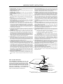
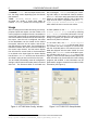
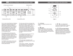
ACT1000 Air-to-Cable Transcoder
INSTRUCTION MANUAL
RF OUTPUT
POWER
ACT1000
is a registered trademark of R. L. Drake, LLC
© Copyright 2011 R. L. Drake, LLC
P/N: 3852564-11-2011
2
TABLE OF CONTENTS AND CAUTION STATEMENTS
Contents
Caution Statements
Important Safety Instructions
Specifications
General Description
Installation and Mounting
Configuration
Usage
Warranty
2
3
4
5
5
5
6
7
Caution Statements
WARNING: TO PREVENT FIRE OR
ELECTRICAL SHOCK, DO NOT
EXPOSE TO RAIN OR MOISTURE
CAUTION
RISK OF ELECTRIC SHOCK
DO NOT OPEN
A product and cart combination should be
moved with care. Quick stops, excessive
force and uneven surfaces may cause the
product and cart combination to overturn.
!
CAUTION: TO REDUCE THE RISK OF ELECTRIC
SHOCK, DO NOT REMOVE COVER. NO USERSERVICEABLE PARTS INSIDE. REFER SERVICING
TO QUALIFIED PERSONNEL
!
The lightning flash with arrow head symbol,
within an equilateral triangle, is intended to
alert the user to the presence of uninsulated
"dangerous voltage" within the product's
enclosure that may be of sufficient
magnitude to constitute a risk of electric
shock to persons.
The exclamation point within an equilateral
triangle is intended to alert the user to the
presence of important operating and
maintenance (servicing) instructions in the
literature accompanying the product.
WARNING:
TO REDUCE THE RISK OF FIRE OR ELECTRIC SHOCK, DO NOT
EXPOSE THIS PRODUCT TO RAIN OR MOISTURE.
DO NOT OPEN THE CABINET, REFER SERVICING TO QUALIFIED
PERSONNEL ONLY.
CAUTION:
TO PREVENT ELECTRIC SHOCK, DO NOT USE THIS (POLARIZED)
PLUG WITH AN EXTENSION CORD RECEPTACLE OR OTHER OUTLET
UNLESS THE BLADES CAN BE FULLY INSERTED TO PREVENT BLADE
EXPOSURE.
ATTENTION:
POUR PREVENIR LES CHOCS ELECTRIQUES, NE PAS UTILISER
CETTE FICHE POLARISEE AVEC UN PROLONGATEUR, UNE PRISE
DE COURANT OU UNE AUTRE SORTIE DE COURANT, SAUF SI LES
LAMES PEUVENT ETRE INSEREES A FOND SANS EN LAISSER
AUCUNE PARTIE A DECOUVERT.
IMPORTANT SAFETY INSTRUCTIONS
1 Read Instructions: All the safety and operating instructions should be
read before the product is operated.
2 Retain Instructions: The safety and operating instructions should be
retained for future reference.
3 Heed Warnings: All warnings on the product and in the operating instructions should be adhered to.
4 Follow Instructions: All operating and use instructions should be followed.
5 Cleaning: Unplug this product from the wall outlet before cleaning. Do
not use liquid cleaners or aerosol cleansers. Use a damp cloth for cleaning.
6 Attachments Do not use attachments that are not recommended by the
product manufacturer as they may cause hazards.
7 Water and Moisture Do not use this product near water—for example,
near a bathtub, wash bowl, kitchen sink or laundry tub; in a wet basement; or near a swimming pool; and the like.
8 Accessories Do not place this product on an unstable cart, stand, tripod, bracket, or table. The product may fall, causing serious injury to
a child or adult, and serious damage to the product. Use only with a
cart, stand, tripod, bracket, or table recommended by the manufacturer,
or sold with the product. Any mounting of the product should follow the
manufacturer's instructions, and should use a mounting accessory recommended by the manufacturer.
9 A product and cart combination should be moved with care. Quick stops,
excessive force, and uneven surfaces may cause the product and cart
combination to overturn.
10 Ventilation Slots and openings in the cabinet are provided for ventilation and to ensure reliable operation of the product and to protect it from
overheating, and these openings must not be blocked or covered. The
openings should never be blocked by placing the product on a bed, sofa,
rug, or similar surface. This product should not be placed in a built-in installation such as bookcase or rack unless proper ventilation is provided
or the manufacturer's instructions have been adhered to.
11 Power Sources This product should be operated only from the type of
power source indicated on the marking label. If you are not sure of the
type of power supplied to your home, consult your product dealer or local
power company. For products intended to operate from battery power,
or other sources, refer to the operating instructions.
12 Grounding or Polarization This product may be equipped with a polarized alternating-current line plug (a plug having one blade wider than
the other). This plug will fit into the power outlet only one way. This is
a safety feature. If you are unable to insert the plug fully into the outlet,
try reversing the plug. If the plug should still fail to fit, contact your electrician to replace your obsolete outlet. Do not defeat the safety purpose
of the polarized plug. Alternate Warnings – If this product is equipped
with a three-wire grounding- type plug, a plug having a third (grounding)
pin, the plug will only fit into a grounding-type power outlet. This is a
safety feature. If you are unable to insert the plug into the outlet, contact
your electrician to replace your obsolete outlet. Do not defeat the safety
purpose of the grounding-type plug.
13 Mise à la terre ou Polarisation Cet appareil est équipé avec un cordon
d'alimentation à trois fils. Il est a brancher sur une prise ayant un connecteur a la terre. Assurez-vous que la connection a la terre ne manque
pas.
3
14 Power-Cord Protection Power-supply cords should be routed so that
they are not likely to be walked on or pinched by items placed upon or
against them, paying particular attention to cords at plugs, convenience
receptacles, and the point where they exit from the product.
15 Lightning For added protection for this product during a lightning storm,
or when it is left unattended and unused for long periods of time, unplug it
from the wall outlet and disconnect the antenna or cable system. This will
prevent damage to the product due to lightning and power-line surges.
16 Power Lines An outside antenna system should not be located in the
vicinity of overhead power lines, other electric light or power circuits,
where it can fall into such power lines or circuits. When installing an
outside antenna system, extreme care should be taken to keep from
touching such power lines or circuits as contact with them may be fatal.
17 Overloading Do not overload wall outlets, extension cords, or integral
convenience receptacles as this can result in a risk of fire or electric
shock.
18 Object and Liquid Entry Never push objects of any kind into this product through openings as they may touch dangerous voltage points or
short-out parts that could result in a fire or electric shock. Never spill
liquid of any kind on the product.
19 Servicing Do not attempt to service this product yourself as opening or
removing covers may expose you to dangerous voltage or other hazards.
Refer all servicing to qualified service personnel.
20 Damage Requiring Service Unplug this product from the wall outlet and
refer servicing to qualified service personnel under the following conditions:
a) When the power-supply cord or plug is damaged,
b) If liquid has been spilled, or objects have fallen into the product,
c) If the product has been exposed to rain or water,
d) If the product does not operate normally by following the operating instructions.
Adjust only those controls that are covered by the operating instructions
as an improper adjustment of other controls may result in damage and
will often require extensive work by a qualified technician to restore the
product to its normal operation, e. If the product has been dropped or
damaged in any way, and f. When the product exhibits a distinct change
in performance—this indicates a need for service.
21 Replacement Parts When replacement parts are required, be sure the
service technician has used replacement parts specified by the manufacturer or have the same characteristics as the original part. Unauthorized
substitutes may result in fire, electric shock or other hazards.
22 Safety Check Upon completion of any service or repairs to this product,
ask the service technician to perform safety checks to determine that the
product is in proper operating condition.
23 Wall or Ceiling Mounting The product should be mounted to a wall or
ceiling only as recommended by the manufacturer.
24 Heat The product should be situated away from heat sources such as
radiators, heat registers, stoves, or other products (including amplifiers)
that produce heat.
ANTENNA
LEAD IN
WIRE
NOTE TO CABLE INSTALLER:
THIS REMINDER IS PROVIDED TO CALL THE
CATV SYSTEM INSTALLER'S ATTENTION TO ARTICLE 820-40 OF THE NEC THAT PROVIDES GUIDELINES FOR PROPER GROUNDING AND, IN PARTICULAR, SPECIFIES THAT THE CABLE GROUND
SHALL BE CONNECTED TO THE GROUNDING
SYSTEM OF THE BUILDING, AS CLOSE TO THE
POINT OF CABLE ENTRY AS PRACTICAL.
GROUND CLAMP
ANTENNA
DISCHARGE UNIT
(NEC SECTION 810-20)
ELECTRIC
SERVICE
EQUIPMENT
GROUNDING CONDUCTORS
(NEC SECTION 810-21)
GROUND CLAMPS
POWER SERVICE GROUNDING
ELECTRODE SYSTEM
(NEC ART 250, PART H)
NEC - NATIONAL ELECTRIC CODE
Figure 1
Example of antenna grounding as per National Electrical Code, ANSI/NFPA 70
4
SPECIFICATIONS
ACT1000 Specifications1
Demodulator Specifications
Input Frequency Range:
Channel plans supported:
Input Channel Bandwidth:
Input RF Level Range:
Input Impedance:
Input Return Loss:
Image Rejection:
Adjacent Channel Rejection:
Noise Figure:
Demodulation Modes:
Symbol Rates:
Modulator Specifications
Modulation Modes:
Symbol Rates:
Frequency Coverage:
Channel Plans:
Max Output Power:
Min Output Power:
Phase Noise:
Broadband Noise:
MER:
Channel Frequency Response:
Carrier Suppression:
I/Q Imbalance:
Output Level Accuracy:
Spurious Emissions:
PSIP Table Handling
PSIP Table Rewriting
MGT/VCT Table Generation
Temperature Rating
Form Factor
Dimensions
Weight
Power Requirements
1
54-1002MHz
Standard CATV, HRC, IRC, Broadcast
6MHz
-33dBmV to +35dBmV, 8VSB
-22dBmV to +35dBmV, 64QAM
-17dBmv to +35dBmV, 256QAM
75 Ohms
>6dB, Broadcast mode; >12dB, CATV mode
80dB
40dB
<9dB, Broadcast mode; <12dB, CATV mode
8VSB ATSC, 64QAM Annex B, 256QAM Annex B
10.76Ms/s (8VSB); 5.057Ms/s (64QAM);
5.3606Ms/s (256QAM)
64, 256QAM ITU j.83 Annex B
16, 32, 64, 128, 256QAM ITU j.83 Annex A
1-7Msps variable, with presets for Annex B
54-1002MHz
Standard CATV, HRC, IRC, Broadcast
+45dBmV max.
+29.5dBmV
−95dBc/Hz@10kHz offset
−75dBc@12MHz offset in a 6MHz bandwidth
>40dB equalized
<1dB
>40dB
<1 degree
±1dB
<-60dBc
Supported
Supported
0-50C ambient
Fits in Drake Digital RMT150 chassis
1.1"W x 3.4"H x 13.25"D
1lb 6oz
All power provided by the Drake® PS151 power supply.
PS151 power requirement: 90-260VAC 150W maximum
with 10 transcoders.
Specifications subject to change without notice or obligation.
DESCRIPTION / INSTALLATION / CONFIGURATION
5
General Description
The R. L. Drake® model ACT1000 is a commercial grade, modular digital headend component providing 8VSB or QAM input to QAM transmodulation
and RF upconversion in a single unit. Up to 10
ACT1000 modules, along with the required PS151
power supply module, can be installed into a single
RMT150 rack mounting tray, occupying only 2 rack
units (3.5''). The ACT1000 supports ATSC 8VSB and
ITU j.83 Annex B 64QAM and 256QAM inputs, and
outputs an agile ITU j.83 Annex A or B QAM channel.
The ACT1000 supports RF inputs from 54-1002MHz
from an antenna or cable feed. The modulator supports RF channels from 54-1002MHZ, and all Annex
A and Annex B QAM modes up to 256QAM, including all interleaver settings for Annex B.
The transcoder demodulates the desired digital
channel, adapts the bitrate from the input to output
if necessary, and modulates the entire multiplex of
programs on the output channel. PCR values are recalculated as required when the input and output bit
rates are not identical, and channel display numbers
(PSIP and MGT/VCT table entries) can be changed.
Installation and Mounting
Install the ACT1000 transcoders into the RMT150
rack frame. Insert each ACT1000 into the frame until the ''F'' connector extends through the front panel
hole, the LED is aligned with the opening in the front
panel, and the hook-shaped projection near the rear
of the ACT1000 engages the rear of the frame. Secure the module into the frame with the supplied nylon washer and 1/2'' ''F'' connector nut.
Connect the supplied power supply cable between
the ACT1000 and the frame-mounted PS151, ensuring that the correct power supply port is used for
the frame slot location (slot 1 is the left-most slot, as
viewed from the front).
Connect the ACT1000's input signal source to
the front-panel ''F'' connector. Connect the rearmounted output ''F'' connector to the output combiner as required for the system configuration. Ensure that the PS151 is plugged into an AC power
source.
When using the RMT150 rack frame, it is not necessary to leave vertical airspace between the frame and
other equipment in the rack, unless other equipment
in the rack specifies minimum gaps. The transcoders
and power supply are designed to provide sufficient
cooling and airflow, even when mounted with adjacent RMT150 units above and below.
Configuration
The ACT1000 is controlled primarily via the Drake
model PS151 front-panel interface. The following menu options are available for configuring the
ACT1000 (menu name listed in bold, valid settings
listed in fixed-width font):
· IN MODE: VSB-8, QAM-64B, QAM-256B – this
configures the input modulation mode that the
ACT1000 will use
· IN PLAN: OTA, CATV, IRC, HRC – this selects
the channel plan for the receiver section (US off-air,
US standard cable, IRC, or HRC respectively)
· IN CHAN: 1-158 – this selects the input channel
number; the range varies depending upon the channel plan selected
· ENCODER: ITU-B, ITU-A – this selects the output modulator QAM mode (ITU j.83 Annex B or Annex A, respectively); for US cable applications, this
should typically be set to ITU-B
· MODULAT:
256-QAM, 128-QAM, 64-QAM,
32-QAM, 16-QAM – this selects the output modulator QAM density; only 256- and 64-QAM modes
are available in Annex B
· INTERLV: All ITU interleave modes supported – this allows the operator to choose a spe-
cific output interleave mode, as necessary (Annex
A mode only supports one interleave mode, as only
one is specified in the standard)
· CLOCK: PRESET, MANUAL – when set to MANUAL
the output symbol rate is continuously variable via
the next setting; when set to PRESET the symbol rate
is fixed at the appropriate bitrate for the modulation
mode chosen
· BD RATE: 1.0000-7.0000 Ms/s – when the
previous setting is configured for MANUAL, this allows the output symbol rate to be configured to an
arbitrary symbol rate. Note that some higher-bitrate
symbol rates may occupy more than 6MHz channel
bandwidth, and that very-low-bitrate symbol rates will
not fill a 6MHz channel
· OUTPUT: NORMAL, STANDBY, CW – changes the
output mode to STANDBY (no output) or CW (a CW
pilot with the correct output power) from NORMAL
· RF OUT: 29.5-45.0dBmV – sets the output power
level of the modulator
· CH PLAN: OTA, CATV, IRC, HRC – sets the
output channel plan in use (US broadcast, US standard cable TV, IRC, or HRC respectively)
6
CONFIGURATION AND USAGE
· CHANNEL: 1-158 – sets the output channel number; the range varies depending upon the channel
plan selected
· PSIP: ORIGINAL, MODIFY, BASIC – the
ACT1000 can modify or insert PSIP tables as
needed. ORIGINAL passes the incoming PSIP ta-
bles unchanged. MODIFY will modify the incoming PSIP tables to user-defined channel numbers,
and BASIC will insert newly-generated PSIP tables
based on user-defined settings; both of these settings must be used in conjunction with the R. L.
Drake Digital Headend Control Program2 ,
which allows the user to set the new values.
Usage
After mounting the ACT1000 and wiring it to the appropriate inputs and outputs, use the PS151 or PC
control program to configure the unit. Remember to
ensure that output levels are matched with all other
sources that will be combined into the final cable system output. Once the unit is configured, the status
of the demodulator can be viewed via the PS151
front panel; select the unit to monitor, and the display will show the current state. The top display line
will switch between the unit ID of the ACT1000 and
the current input channel, and the bottom display
line will show the current SNR. If the demodulator
is not locked to the input signal, the bottom display
line will show TUNELOCK to let the user know that the
ACT1000 is trying to tune in and lock to the input.
be field updated via the R. L. Drake Digital
Headend Control Program as well, by choosing
Tools ⇒Download from the initial screen. This update process is fault-tolerant; if the unit loses power
during an upgrade, the process can simply be restarted once power is restored.
The ACT1000 automatically saves all configuration
settings, and will restore them after power is restored
after loss. The firmware within an ACT1000 can
To set PSIP data, the R. L. Drake Digital
Headend Control Program must be used. Once
the software has been configured to communicate
with the ACT1000 (refer to the manual on the CDROM that shipped with the Drake PS151 for more
details), click View/Edit on the ACT1000 in question, and then click on the PSIP Setup button (see
Figure 1). Once the PSIP Setup window opens, the
table information can be extracted from the existing
programs and modified, or new information can be
generated for program streams that contain no PSIP
information (see Figure 2).
Figure 1: ACT1000 Main Config. Window
Figure 2: ACT1000 PSIP Setup Window
2
version 3.8 or later must be used – the newest version can be downloaded from
http://giant.rldrake.com/RLDrake_Digital_Headend_Control.zip
WARRANTY
7
Three Year Limited Warranty
R.L. DRAKE LLC warrants to the original purchaser this product shall be free from defects in
material or workmanship for three (3) years from the date of original purchase.
During the warranty period R.L. DRAKE LLC or an authorized Drake service facility will provide,
free of charge, both parts and labor necessary to correct defects in material and workmanship. At
its option, R.L. DRAKE LLC may replace a defective unit.
To obtain such a warranty service, the original purchaser must:
1. Retain invoice or original proof of purchase to establish the start of the warranty period.
2. Notify R.L. DRAKE LLC or the nearest authorized service facility, as soon as possible after
discovery of a possible defect, of:
a) the model and serial number,
b) the identity of the seller and the approximate date of purchase; and
c) A detailed description of the problem, including details on the electrical connection to
associated equipment and the list of such equipment.
3. Deliver the product to R.L. DRAKE LLC or the nearest authorized service facility, or ship the
same in its original container or equivalent, fully insured and shipping charges prepaid.
Correct maintenance, repair, and use are important to obtain proper performance from this product.
Therefore carefully read the Instruction Manual. This warranty does not apply to any defect that
R.L. DRAKE LLC determines is due to:
1. Improper maintenance or repair, including the installation of parts or accessories that do not
conform to the quality and specifications of the original parts.
2. Misuse, abuse, neglect or improper installation.
3. Accidental or intentional damage.
All implied warranties, if any, including warranties of merchantability and fitness for a particular
purpose, terminate three (3) years from the date of the original purchase.
The foregoing constitutes R.L. DRAKE LLC'S entire obligation with respect to this product, and the
original purchaser shall have no other remedy and no claim for incidental or consequential damages, losses or expenses. Some states do not allow limitations on how long an implied warranty
lasts or do not allow the exclusions or limitation of incidental or consequential damages, so the
above limitation and exclusion may not apply to you.
This warranty gives you specific legal rights and you may also have other rights which vary from
state to state. This warranty shall be construed under the laws of Ohio.
For Service, contact:
R.L. DRAKE LLC
230 Industrial Drive
Franklin, Ohio 45005 U.S.A.
Customer Service and Parts Telephone: +1 (937) 746-6990
Telefax: +1 (937) 806-1576
Web Site: http://www.rldrake.com
R.L. Drake LLC
230 Industrial Drive
Franklin, Ohio 45005 U.S.A.
Customer Service and Parts Telephone: +1 (937) 746-6990
Telefax: +1 (937) 806-1576
World Wide Web Site: http://www.rldrake.com