1
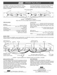
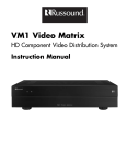
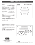
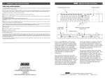
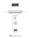
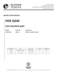
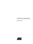
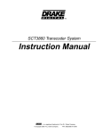
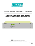
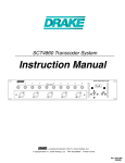
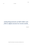
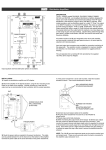
1
FRONT PANEL CONTROLS AND INDICATORS
TMQAM and TMQAMasi DIGITAL QAM MODULATORS
TM
12 POSITION RACK MOUNT
2
POWER SUPPLY
TMQAMasi
F1
POWER SUPPLY
POWER
ERROR
QAM
MODULATOR
BIT RATE
19.327 M
TMQAMasi
TMQAM
3
5
ENTER
POWER
ERROR
QAM
MODULATOR
BIT RATE
19.327 M
ENTER
GAIN
3
5
CATV+100
CATV
DUC860
DUC550
DUC860
DUC550
TMQAMasi
TMQAM
POWER
ERROR
QAM
MODULATOR
BIT RATE
19.327 M
3
5
ENTER
GAIN
POWER
ERROR
QAM
MODULATOR
BIT RATE
19.327 M
ENTER
PS8
F2
QAM
MODULATOR
BIT RATE
19.327 M
F4
3
5
ENTER
CATV+100
CATV
GAIN
F3
F3
GAIN
F4
TMQAMasi MODULATOR
The R.L. Drake model TMQAM and TMQAMasi
modulators are professional quality modular
digital headend components designed to
provide optimum performance with minimized
rack space requirements. These modulators
accept an MPEG2 transport stream input in
either the SPI format or ASI serial format,
depending on the model, and is capable of
providing a QAM output with 16, 32, 64, 128,
or 256 constellation points.
The modulators perform the forward error
correction (FEC) encoding according to ITU
J.83 Annex A or Annex B. Annex A is referred
to as ‘DVB’ and Annex B is referred to as
‘DigiCipher II®’. The front panel push-buttons
and display provide full access to many other
parameters that can be set to match a
particular application.
The TMQAM model provides a choice of two
clock modes. In the ‘Auto’ mode, the output
clock rate is automatically locked to the
incoming data clock rate.
TMQAM MODULATOR
Thus the output symbol rate can change if the
input data rate changes. The TMQAMasi model
does not have an "Auto" selection. In the
‘Fixed’ mode, the desired output symbol rate is
programmed from the front panel. This rate
must be equal to or greater than the incoming
data rate. The output rate will be maintained at
the set rate and if the input rate is slower than
this rate, the TMQAM and TMQAMasi will add
null packets to make up for the slower
input rate.
The modulators have several test modes that
can be selected. In these modes, a
pseudo-random binary sequence stream is
substituted for the input source. This will
provide a modulated output without any
external input source.
A CW output mode is selectable to allow
measurement of the output level with an analog
signal meter.
The RF output is +30 dBmV. This IF output
can be connected to one of the DRAKE DUC
series of digital upconverters to provide an
output on a CATV or broadcast channel.
Figure 1
F1 - LCD Display
Displays the modulator parameter and its
setting.
F3 -
Left and Right Button
Use the Left and Right buttons to select the
parameter you desire to view or adjust.
ENTER
ENTER
F2 Use the ENTER button to enter the adjust
mode or to save and load a new parameter
value. Hold for 2 seconds to enter the adjust
mode. After adjustment, press this button once
to load and save the value.
F4 Up and Down Buttons
Use the Up and Down buttons to adjust a
parameter value when in the adjust mode.
When not in the adjust mode, the UP button
displays the version number. The Down button
displays the incoming bit rate if the "AUTO"
clock mode has been selected.
REAR PANEL CONNECTIONS
R4
R1
CONNECTIONS AND CONTROLS
All connections to and from each modulator are
made through the rear panel. Refer to Figure 4
for correct cable and wiring connections.
44 MHz
IF OUTPUT
44 MHz
IF OUTPUT
R5
ASI TRANSPORT
STREAM INPUT
POWER
+12 V
14
1
R6
POWER
+12 V
POWER
SUPPLY
QAM MODULATOR
UNITS
DUC550 OR DUC860
UPCONVERTERS
GND
GND
+5 V
Figure 2
+5 V
Figure 3
IF IN
R1 - 44 MHz IF OUTPUT Connector
This is the modulator output. The level is
+30 dBmV.
R4 - 44 MHz IF OUTPUT Connector
This is the modulator output. The level is
+30 dBmV.
R2 - 25 Pin SPI LVDS INPUT Connector
This is the MPEG2 transport stream input DVB Synchronous Parallel Interface. The levels
comply with low voltage differential signalling
specifications.
R5 - 75 Ohm, Type BNC Connector
This is the MPEG2 transport stream input; ASI
input, asynchronous serial interface.
R3 - DC Power Connector
This is the power input connector. Connect to a
Drake PS8 or equivalent power supply,
(12 V @ 0 mA, 5 V @ 380 mA for the SPI
input version).
R6 - DC Power Connector
This is the power input connector. Connect to a
Drake PS8 or equivalent power supply,
(12 V @ 0 mA, 5 V @ 500 mA for the ASI
input version).
12V GND 5V
90-260 VAC
DC OUTPUTS X 8
AC POWER
CORD
RF OUT
SPI LVDS INPUT
POWER
44 MHz
IF OUTPUT
POWER
POWER
44 MHz
IF OUTPUT
POWER
POWER
RF OUT
RF OUT
TO QAM
DISTRIBUTION
Figure 4
TMQAM OPERATION AND SETUP
The TMQAM provides user access to many
parameters of the modulator so that it can be
setup to precisely match the requirements of
the system.
1) To VIEW parameter settings only – no
adjustment:
Press either the left or right arrow buttons to
scroll through each parameter page. The
parameter is listed on the first line of the display
and the present setting will be displayed on the
second line. After viewing, press the left or right
arrow button again to advance to the next
parameter. After viewing, the display will
time-out and return to the output baud (BD)
rate/symbol rate page.
IF IN
IF IN
IF IN
44 MHz
IF OUTPUT
POWER
POWER
SPI LVDS INPUT
SPI LVDS INPUT
R3
4
RACK MOUNTING
Adequate ventilation is very important in
multichannel installations. Units should be
spaced apart by at least one panel height
wherever possible, and some air movement is
mandatory in enclosed rack cabinets.
Excessive heat will shorten component life and
modulator performance will be degraded
without proper cooling.
SPI LVDS INPUT
13
25
R2
INSTALLATION
SPI LVDS INPUT
3
44 MHz
IF OUTPUT
POWER
RF OUT
FROM SATELLITE
DEMODULATOR OR
OTHER LVDS DATA
STREAM
2) To ADJUST or change parameter settings
or for initial set up, follow these steps:
Press and hold the enter button for 2 to 3
seconds until the display begins to flash. Press
the left or right arrow button to scroll to the
desired parameter. Now press the up or down
arrow button to adjust the parameter value.
Note that no change is made at this point until
the new value is loaded and saved. When the
value is adjusted to the value required, press
the enter button again. This will load and save
the new value until this procedure is repeated.
5
CHART OF DISPLAY MENUS
SETUP PROCEDURES
128, J 4
32, J 4
128, J 3
64, J 2
128, J 2
128, J 1
1, J 128
128, J 8
2, J 64
128, J 7
4, J 32
128, J 6
8, J 16
128, J 5
16, J 8
18%
FOR
BIT RATE
DISPLAY
(ONLY IN AUTO CLOCK)
12, J 17
15%
The following information may serve as an aid in
setting up the TMQAM parameters.
Use the procedure on page 4 to enter the adjust
mode. Select the SOURCE menu. Normally, the
EXTERNAL selection would be used to select the
MPEG2 transport stream input. The PRBS
selections provide test sequences generated
inside the TMQAM and are for testing the
modulator without a MPEG2 input source.
Advance to the next menu using the left or right
arrow buttons. Continue this process until all
parameters have been checked and/or adjusted.
Press the ENTER button to load and store all
adjusted parameters. The ENTER button can be
used after each parameter adjustment or, if
desired, wait until all parameter adjustments are
set and then "ENTER" adjustments all at once.
Most CATV systems are using 64QAM or
256QAM for digital video. In the ITU-B mode, the
only choices are 64QAM or 256QAM.
The INPUT menu is used to select an inverted
clock if this is required. Usually the NORM
selection for normal clock will be required. Select
INV if an inverted clock is used.
The CLOCK menu allows selection of the clock
mode of operation. If AUTO is selected, the output
baud or symbol rate will automatically track that of
the input stream. If FIXED is selected, the output
rate will remain fixed at this setting and the
TMQAM will add null packets where required if
the input rate is slower. If the input rate exceeds
the fixed manual setting, an error will result.
Some set top boxes are designed to operate at
only one fixed symbol rate. If this is the case for
your installation, use FIXED setting and set the
value in the next menu to match that of the set top
box. Advance one menu with the right arrow. This
BD RATE menu will display the output symbol
rate. If a fixed setting is required, use the BD
RATE page to make the selection.
64
256
The OUTPUT menu is used to select the output
mode. The CW setting is for testing and should be
selected to allow setting of the upconverter output
level using a device such as a signal level meter
or spectrum analyzer. For normal operation, one
of the MOD settings is required. If the output
upconverter uses high side local oscillator
injection and inverts the output spectrum of the
TMQAM (the Drake DUC upconverters do this),
select the MOD-INV setting to provide a normal
output from the upconverter. If the upconverter
does not invert the spectrum or if you are use the
44 MHz IF output directly, you may need to select
the MOD-NORM setting.
The TMQAMasi operates in fixed mode only.
*Auto clock mode is only available in the TMQAM, SPI input model.
-
DVB
DAVIC
TU-A
TU-B
1 Hz
10 Hz
20 Hz
100 Hz
CW
MOD-INV
MOD-NORM
FOR TU-B MODE
AUTO*
FIXED
16
32 (DVB only)
64
128 (DVB only)
256
BD RATE:
DISPLAYS
OUTPUT
SYMBOL
RATE.
CLOCK:
INTERLV
QAM:
MODE:
LOOP BW:
OUTPUT:
INPUT:
CLK-NORM
CLK-INV
SOURCE:
EXTERNAL
PRBS 23M
PRBS 23
PRBS 15M
PRBS 15
ENCODER:
FOR TU-A MODE
ALPHA:
ADJUST
RATE IF
FIXED CLOCK
IS
SELECTED.
FOR
FIRMWARE
VERSION (WHEN NOT
IN ADJUST MODE)
The following chart shows all choices that are
available for each parameter.
6
The LOOP BW menu is used to adjust the loop
bandwidth of the input tracking loop. Use 20 Hz as
a default setting. In some cases, this may need to
be changed – 100 Hz if the signal is very jittery or
1 Hz if stable and weak. 20 Hz or 10 Hz are
usually best for most sources.
The MODE menu is used to select the desired
forward error correction mode. This must match
that of the demodulating device (set top box, etc).
Select ITU-A for DVB applications or select ITU-B
for DigiCipher II® applications.
The ENCODER menu is used only if ITU-A was
set as a mode. Select DVB or DAVIC mapping as
required.
The QAM menu is used to select the QAM order
desired. 16QAM, 32, 64, 128, or 256QAM may be
selected in the ITU-A mode.
The ALPHA menu displays the roll-off setting for
the baseband filtering. ITU-A is 15% and ITU-B is
18% excess bandwidth. THESE CANNOT BE
CHANGED.
The INTERLV menu allows setting of the
interleaver values. The ITU-A setting is fixed at
I=12, J=17. The ITU-B mode allows many
combinations. The required setting should be
specified by the system designer. If the demodulating device must have a particular set of values,
then select the appropriate matching setting. For
ITU-B, many systems use I128, J4 or I128, J1.
The BD RATE menu displays the current output
symbol rate or baud rate. If the FIXED option has
been selected for the clock, use this menu to
adjust the output rate to the desired rate. When
timed out from the set up process or adjust mode,
the BD RATE page will be the default display
menu. If the Auto Clock selection has been
made, this menu will be skipped in the adjust
mode. You can check bit rate or firmware version
using the procedure described below.
DEFAULT DISPLAY /FIRMWARE REVISION / BIT
RATE: After making and saving the above
adjustments, the display will time out and default
to the BD RATE screen showing the output baud
rate or symbol rate. When this menu is being
displayed and you are not in the adjust mode,
pressing the up arrow will display the firmware
revision number. If the down arrow is pressed, the
display will display the data bit rate. Press the
down arrow button again to go back to displaying
the output baud rate.
7
SPECIFICATIONS
WARRANTY
8
THREE YEAR LIMITED WARRANTY
Output
Output Frequency: 44 MHz.
Output Level: +30 dBmV.
Output Impedance: 75 Ohms.
Spurious Outputs: -55 dBc typical, in band or
in adjacent channels.
-60 dBc otherwise when
used with Drake DUC550
or DUC860 upconverter
modules.
MER: 38 dB minimum.
Modulation
Mode: 16, 32, 64, 128, 256 QAM.
Symbol Rate: 7.0 Msymbols/s Max.
Excess Bandwidth: 15% (ITU-A), 18% (ITU-B).
FEC Encoding
FEC Modes: DVB/DAVIC
(ITU-T J.83 Annex A),
Digicipher® II
(ITU-T J.83 Annex B).
Input
Transport Stream: TMQAM - Parallel Input
according to DVB SPI, LVDS
specifications.
TMQAMasi - Serial input
according to DVB ASI
specifications.
Connector: TMQAM - DB25 Female.
TMQAMasi - BNC, 75 Ohms.
General
DC Power Required: TMQAM - 5 VDC @
380 mA.
TMQAMasi - 5 VDC @
500 mA.
Size: 2.06" W x 3.5" H x 9.25" D
(5.23 cm W x 8.9 cm H x
23.5 cm D).
Weight: 1 lb. 2 oz. (0.51 Kg).
R.L. DRAKE COMPANY warrants to the original purchaser this product shall be free from defects in material or workmanship for three (3)
years from the date of original purchase.
During the warranty period the R.L. DRAKE COMPANY or an authorized Drake service facility will provide, free of charge, both parts and
labor necessary to correct defects in material and workmanship. At its option, R.L. DRAKE COMPANY may replace a defective unit.
To obtain such warranty service, the original purchaser must:
(1) Retain invoice or original proof of purchase to establish the start of the warranty period.
(2) Notify the R.L. DRAKE COMPANY or the nearest authorized service facility, as soon as possible after discovery of a possible defect,
of:
(a) the model and serial number,
(b) the identity of the seller and the approximate date of purchase; and
(c) A detailed description of the problem, including details on the electrical connection to associated equipment and the list of such
equipment.
(3) Deliver the product to the R.L. DRAKE COMPANY or the nearest authorized service facility, or ship the same in its original container
or equivalent, fully insured and shipping charges prepaid.
Correct maintenance, repair, and use are necessary to obtain proper performance from this product. Therefore carefully read the Instruction
Manual. This warranty does not apply to any defect that R.L. DRAKE COMPANY determines is due to:
(1) Improper maintenance or repair, including the installation of parts or accessories that do not conform to the quality and specifications
of the original parts.
(2) Misuse, abuse, neglect or improper installation.
(3) Accidental or intentional damage.
All implied warranties, if any, including warranties of merchantability and fitness for a particular purpose, terminate three (3) years from the
date of the original purchase.
The TMQAM and TMQAMasi modulator can operate in either of two clock modes:
1) It can automatically lock to the incoming bit rates producing an output rate determined by the input
stream. Power should be supplied by the model PS8 power supply module which also mounts into
the DRMM12. The PS8 and DRMM12 are sold separately.
The foregoing constitutes R.L. DRAKE COMPANY’S entire obligation with respect to this product, and the original purchaser shall have no
other remedy and no claim for incidental or consequential damages, losses or expenses. Some states do not allow limitations on how long
an implied warranty lasts or do not allow the exclusions or limitation of incidental or consequential damages, so the above limitation and
exclusion may not apply to you.
This warranty gives you specific legal rights and you may also have other rights which vary from state to state. This warranty shall be
construed under the laws of Ohio.
2) It can be set, from front panel controls, to output a desired symbol rate using an internally
generated clock. In this mode, when the input bit rate is less than that needed to produce the set
output symbol rate, null packets are added by the modulator.
The QAM signal must be up-converted to the desired channel with the Drake Up-Converter
module, prior to transmission on the cable plant.
Specifications subject to change without notice or obligation.
Pin Out DVB SPI Interface
25
14
13
1
1 Data Clk +
2 GND
3 Data 7 +
4 Data 6 +
5 Data 5 +
6 Data 4 +
7 Data 3 +
8 Data 2 +
9 Data 1 +
10 Data 0 +
11 Data Valid +
12 Start of Packet +
13 GND
14 Data Clk 15 GND
16 Data 7 17 Data 6 18 Data 5 19 Data 4 20 Data 3 21 Data 2 22 Data 1 23 Data 0 24 Data Valid 25 Start of Packet -
R.L. DRAKE COMPANY
230 INDUSTRIAL DRIVE
FRANKLIN, OHIO 45005 U.S.A.
CUSTOMER SERVICE AND PARTS TELEPHONE: +1 (937) 746-6990
TELEFAX: +1 (937) 743-4576
WORLD WIDE WEB SITE: http://www.rldrake.com
TM
is a trademark of the R.L. Drake Company
® is a registered trademark of the R.L. Drake Company
© Copyright 2003 R.L. Drake Company
P/N: 3852372D-1-2003
Printed in the U.S.A.