1
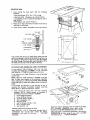
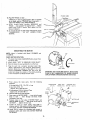
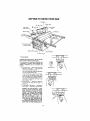
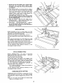
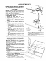
2 ELEVATION
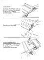
HANDWHEEL...
elevates
orlowers
the
blade.Turnclockwise
to elevate
... counterclockwise
tolower,
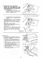
Select a suitable piece of smooth straight wood..,
two holes through it and attach it with screws.
drill
NOTE; When bevel crosscutting, attach facing so that it
extends to the right of the miter gauge and use the
miter gauge in the groove to the right of the blade.
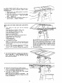
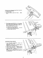
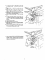
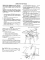
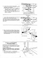
3 TILT HANDWHEEL
... tilts the bladefor bevel
' cutting. Turn clockwiseto tilt towardleft ...
counterclockwise to tilt toward right,
When the blade is tilted to the LEFT as far as it will go,
it should be at 45 ° to the table and the bevel pointer
should point 45 ° .
NOTE: There are LIMIT STOPS inside the saw which
prevent the blade from tilting beyond 45 ° to the LEFT
and 90 ° to the RIGHT. (See "Adjustments"
section
"Blade Tilt, or Squareness of Blade to Table"),
4
5
TILT
LOCK HANDLE
... locks the blade in the
desired tilt position. To loosen, turn counterclockwise,
Push handle in and turn it to another position if
necessary in order to tighten or loosen.
AUXIELIARY
STOP
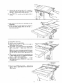
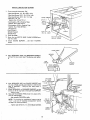
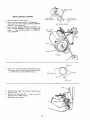
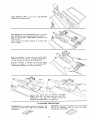
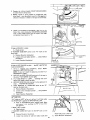
When replacing the guard, make sure the PIN in the rod
engageswith the NOTCH in the spreader support, Make
sure thumbscrew is tightened securely,
8
ROUND
WOOD
HEAD
\
To remove the guard for special operations, loosen the
thumbscrew and slide the guard off of the rod. DO
NOT DISTURB THE SETTING OF THE ROD.
\
#!0
FACING
"\
BLADEGUARD
must always be in place and working
properly for all thru-sawing cuts. That is, all cuts
whereby
the blade cuts completely through the
workpiece.
FACING
\\
45 ° SLOT
FOR STOP PIN
RIP FENCE
.. is locked in place by tightening the
lock knob. To move the fence, loosen the knob and
grasp the fence with one hand at the front.
Holes are provided in the rip fence for attaching a wood
facing when using the dado head, or molding head.
Select a piece of smooth straight wood approx. 3/4 in.
thick and the same size as the rip fence.
Attach it to the fence with three Round Head ##10
Wood Screws 2 in. long. To remove the facing, loosen
the screws, slide the facing forward and pull the screws
through the round holes.
WOOD
PIN
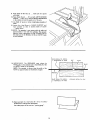
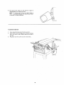
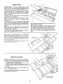
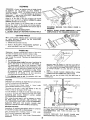
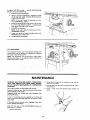
TABLE INSERT is removable for removing or installing
blades or other cutting tools.
///
SCREWS
/
SCREW
6
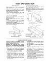
MITER GAUGE ... head is locked in position for
crosscutting or mitering by tightening the lock knob.
ALWAYS LOCK IT SECURELY WHEN NUSE.
There are two slots for the stop pin at the 45 degree
right and left positions for conveniently setting the
Vliter Gauge to cut miters.
NOTE: The slots for the stop pin and the graduations
are manufactured to very close tolerances which
provide accuracy for average woodworking. In some
caseswhere extreme accuracy is required, when making
angle cuts, for example, make a trial cut and then
recheck
WARNING:
FOR YOUR OWN SAFETY,
TURN
SWITCH
"OFF"
AND REMOVE
PL.UG FROM
POWER SOURCE OUTLET
BEFORE REMOVING
INSERT.
it.
If necessary, the miter gauge head can then be swiveled
slightly to compensate and then locked.
Slots are provided in the miter gauge for attaching an
AUXILIARY
FACING to make it easier to cut long
p=eces. Be positive facing does not interfere with the
proper operation of the sawblade guard.
A,
B.
Lower the blade below the table surface.
Raise blade guard.
C.
Loosen Screw.
D.
Lift in_ert from
front of saw.
front
end, and pull toward
NEVER
OPERATE
THE SAW WITHOUT
THE
PROPER INSERT IN PLACE. USE THE SAW BLADE
INSERT
WHEN
SAWING
. . . USE THE
COMBINATION
DADO MOLDING
INSERT WHEN
DADOING OR MOLDING.
21