1
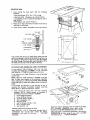
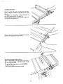
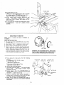
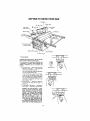
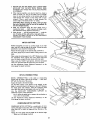
To remove insert.
A) Loosen Screw
B)
Lift insert from front end, and pull toward front of
saw,
4.
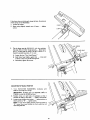
To replace insert.
Place insert into insert opening in table and push
toward rear of saw to engage spring clip and until
keyslot in insert will drop over screw. Tighten screw.
Do not tighten screw to the point where it will deflect
the insert.
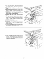
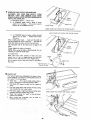
CHECKING
BLADE SQUARENESS TO TABLE
IMPORTANT: BLADE must be SQUARE (g0 °) to TABLE,
in order to proceed with assembly.
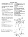
To check for blade squareness, refer to "BLADE TILT, OR
SQUARENESS OF BLADE TO TABLE" adjustment on
page 30.
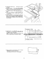
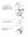
CHECKING
IMPORTANT:
groove,
BLADE FOR HEEL
Saw blade MUST be parallel to miter gauge
To check
for parallelism,
refer
to "HEELING
ADJUSTMENT OR PARALLELISM
OF SAWBLADE TO
MITER GAUGE GROOVE" adjustment on page 29 and 30.
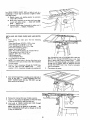
ASSEMBLING
STEEL LEGS
NOTE: Steel Legs are furnished with Model 113.298031
and 113,298151.
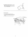
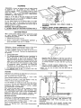
From among the loose parts, find the
following Hardware:
24 Truss Head Screws, 1/4 - 20 X 5/8 in. long (top of
screw is rounded)
SIDE STIFFENER
24 Lockwashers, 1/4 in. External Type (approx. dia, of
hole 1/4 in.)
24 Hex Nuts, 1/4 - 20 (approx. dia. of hole 1/4 in.)
8 Hex Nuts, 1/2 - 13 (approx. dia. of hole 1/2 in.)
4 Leveling feet.
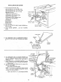
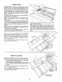
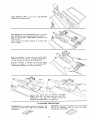
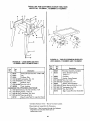
Assemble the legs as shown .,.
1. Insert the Truss Head Screws through the holes in the
legs, then through the holes in the stiffeners. MAKE
SURE THE SCREWS GO THROUGH THE HOLES IN
THE SIDE STIFFENERS MARKED "×".
2. Install the Iockwashers ... screw on the nuts but do
not tighten until completely assembled.
3. Install leveling feet.
END
STIFFENER"
IN.
_
HEX
NUTS
LEVELING FOOT