1
--w.
i lull l
i,,,,it,lllll,,i
OWNER'S
MANUAL
MODEL NO.
917.255575
®
12,5 HP _C
ELECTRIC START
3 6n One Convertible
38" MOWER DECK
6 SPEED TRANSAXLIE
LAWN TRACTOR
Caution:
Read and follow
all Safety Rules
and Instructions
Before Operating
This Equipment
oAssembiy
° Operation
o Customer Responsibilities
o Service and Adjustment
o Repair Parts
Sears,
= u nmH,,,,,u
Roebuck
i nnH,H,
and Co., Hoffman
, UHI,,
Estates,
'H,
IL 60179 U.S.A.
I ,,',,,',', ..........................................
::
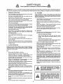
SAFETY RULES
Safe Operation
Practices
for Ride-On
Mowers
IMPORTANT: THIS CUTTING MACHINE IS CAPABLE OF AMPUTATING HANDS AND FEETANDTHROWING
OBJECTS.
FAILURE TO OBSERVE THE FOLLOWING SAFETY INSTRUCTIONS COULD RESULT iN SERIOUS INJURY OR DEATH.
Io
GENERAL
o
Read, understand, and follow all instructions in the manual
and on the machine before starting
Only allow responsible adults, who are familiar with the
instructions, to operate the machine
Clear the area of objects such as rocks, toys, wire, etc,
which could be picked up and thrown by the blade,
Be sure the area is clear ofother people before mowing. Stop
machine if anyone enters the area.
Never carry passengers.
Do not mow in reverse unless absolutely necessary, Always
iook down and behind before and while backing.
Tragic accidents can occur if the operator is not alert to the
presence of children Children are often attracted to the machine
and the mowing activity. Neverassume that children will remain
where you last saw them.
Be aware of the mower discharge direction and do not point
it at anyone
Do not operate the mower without either the
enttre grass catcher or the guard in place
Slow down before turning.,
Never leave a running machine unattended. Always turn off
blades, set parking brake, stop engine, and remove keys
before dismounting
Turn off blades when not mowing,
Stop engine before removing grass catcher or unclogging
chute
•
•
•
•
•
•
•
•
•
•
•
•
•
•
ii.
OPERATION
III.
CHILDREN
•
Keep children out ofthe mowing area and under the watchful
care of another responsible adult
Be alert and turn machine off if children enter the area.
•
Mow only In daylight or good artificial light
Do not operate the machine while under the influence of
alcohol or drugs
Watch for traffic when operating near or crossing roadways
Use extra care when loading or unloading the machine into
a trailer mr truck.
•
Before and when backing, look behind and down for smaU
children,
•
Never carry children. They may fall off and be seriously
injured or interfere with safe machine operation,
Never allow chtldren to operate the machine
Use extra care when approaching blind corners, shrubs,
trees, or other objects that may obscure vision.
IV,
SERVICE
•
Use extra care in handling gasoline and other fuets Theyare
flammable and vapors are explosive
Use only an approved container
Never remove gas cap or add fuel with the engine
running Allow engine to coo! before refueling
Do not
smoke.
Never refuel the machine indoors
Never store the machine or fuel container inside where
there is an open flame, such as a water heater.
Never run a machine inside a closed area.
.
•
Keep nuts and bolts, espectally blade attachment bolts, tight
and keep equipment in good condition
Never tamper with safety devices.
Check their proper
operation regularly
Keep machine free of grass leaves, or other debris build-up
Clean o I or fuel sp Itage. Allow machine to cool before
storing.
Stop and inspect the equipment if you strike an object
Repair, if necessary, before restarting
Never make adjustments or repairs with the engine running
SLOPE OPERATION
Slopes are a major factor related to Ioss_of-controland tlpover
accidents, which can result in severe injury or death. All slopes
require extra caution. If you cannot back up the slope or if youfeel
uneasy on it, do not mow it.
.
DO:
•
Mow up and down slopes, not across.
•
Remove obstacles such as rocks, tree limbs, etc
•
Watch for holes, ruts, or bumps. Uneven terrain could
overturn the machine. Tall grass can hide obstacles,
Use slow speed. Choose a low gear so that you will not have
to stop or shift while on the slope.
•
Follow the manufacturer's recommendations for wheel
weights or counterweights to improve stability,
•
Use extra care with grass catchers or other attachments.
These can change the stability of the machine.
•
Keep all movement on the slopes slow and gradual Do not
make sudden changes in speed or direction
•
Avoid starting or stopping on a slope. If tires lose traction,
disengage the blades and proceed slowly straightdown the
slope
DO NOT:
"
Donottumonslopesunlessnecessary, andthen, turnslowty
and gradually downhill, if possible.
•
Do not mow near drop-offs, ditches, or embankments The
mower could suddenly turn over if a wheel is over the edge
of a cliff or ditch, or ff an edge caves in.
•
Do not mow on wet grass. Reduced traction could cause
sliding,
•
Do not trytostabilize the machine by puttingyour foot on the
ground.
•
Do not use grass catcher on steep slopes
•
•
Grasscatcher components are subject to wear, damage, and
deterioration, which could expose moving parts or allow
objects to be thrown. Frequently check components and
replacewith manufacturer's recommended parts, when necessary_
Mower blades are sharp and can cut. Wrap the bfade(s) or
wear gloves, and use extra caution when servicing them
Check brake operation frequently.
Adjust and service as
required.
•
•
i,.u..."ITT"I.IIIII.IIIrI"
|
,1111,1
....
II III
I
._,
Look for this symbol
|
i
._/_
tant safety precautions.
It means
CAUTiONIII BECOMEALERTIH
YOUR
SAFETY IS INVOLVED.
I
_
to point out leper-
.... _j
CAUTION:
Always disconnect
spark
contact spark plug in order to prevent
plug wire and place wire where it cannot
accidental starting when setting, up,
transporting,
adjusting
or making
repairs.
2
_
I
g
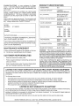
PRODUCT
CONGRATULATIONS
on your purchase of a Sears
tractor. It has been designed, engineered and manufactured to give you the best possible dependability and
performance.
Should you experience any problem you cannot easily
remedy, please contact your nearest Sears Service
Center/Department,
We have competent, welt-trained
technicians and the proper tools to service or repair this
tractor,
Please read and retain this manual The instructions will
enable you to assemble and maintain your tractor properly, Always observe the "SAFETY RULES",
MODEL
NUMBER
917,255575
SPECIFICATIONS
HORSEPOWER:
12,5
GASOLINE CAPACITY:
5 QUARTS
UNLEADED REGULAR
OIL (3 0 PINTS):
SAE 30 (Above 32°F)
5W-30 (Below 32°F)
SPARK PLUG (GAP030 IN):
CHAMPION RJ-19LM
STD361458
VALVE CLEARANCE:
INTAKE:
,005 - ,007 IN ,,
EXHAUST: °009 - .011 IN
GROUND SPEED:
FORWARD:
1st
110
2rid
1,40
3rd
2.00
4th
3,00
5th
4_20
6th
5,00
REVERSE: 150
SERIAL
NUMBER
DATEOFPURCHASE
THE MODELAND SERIAL NUMBERS WILL BE FOUND
ON A PLATE UNDER THE SEAT,
YOU SHOULD RECORD BOTH SERIAL NUMBERAND
DATE OF PURCHASE AND KEEP IN A SAFE PLACE
FOR FUTURE REFERENCE,
MAINTENANCE
AGREEMENT
RESPONSIBILITIES
.
Read and observe the safety rules.
•
Follow a regular schedule in maintaining, caring for and
using your tractor.
•
Fotlow the instructions under "Customer Responsibilities" and "Storage" sections of this manual.
,,,,
i J
i m ii
n,i
TIRE PRESSURE:
FRONT:
REAR:
CHARGING SYSTEM:
3 AMPS BATTERY
5 AMPS HEADLIGHTS
BLADE BOLT TORQUE:
30-35 FT. LBS,
in the state of California the above is required by law
(Section 4442 of the California Public Resources Code).
Other states may have similar laws. Federal laws apply on
federal lanas. A spark arrester for the muffler is available
through your nearest Sears authorized service center (See
the REPAIR PARTS section of this manual).
,Ul,
iii
LIMITED TWO YEAR WARRANTY
14 PSI
12 PSI
WARNING:
This tractor is equipped with an internal
combustion engine and should not be used on or near any
unimproved forest-covered, brush-covered or grass-covered land unless the engine's exhaust system is equipped
with a spark arrester meeting applicable local or state taws
(if any), If a spark arrester is used, it should be maintained
in etiective working order by the operator.
A Sears maintenance agreement is available on this tractor Contact your nearest Sears store for details
CUSTOMER
MPH
MPH
MPH
MPH
MPH
MPH
MPH
ON ELECTRIC
i,,,
, ............... lip1
START RIDING EQUIPMENT
For two (2) years from the date of purchase, if this riding equipment is maintained, lubricated and tuned up according to the
instructions in the owner's manual, Sears will repair or replace, free of charge, any parts found to be defective in material or
workmanship,
This Warranty does not cover:
Expendable items which become worn during normal use, such as blades, spark plugs, air cleaners and belts.
Tire replacement or repair caused by puncturesfrom outside objects, such as nails, thorns, stumps, or glass°
Repairs necessary because of operator abuse, negligence, improper storage or accident or the failure to maintain the
equipment according to the instructions contained in the owner's manual.,
Riding equipment used for commercial or rental purposes.
LIMITED 90 DAY WARRANTY
ON BATTERY
For 90 days from date of purchase, if any battery included with this riding equipment proves defective in material or workmanship
and our testing determines the battery will not hold a charge, Sears will replace the battery at no charge,
WARRANTY SERVICE IS AVAILABLE BY RETURNING THE RIDING EQUIPMENT TO THE NEAREST SEARS SERVICE
CENTER/DEPARTMENT IN THE UNITED STATES
This Warranty gives you specific legal rights, and you may also have other rights which may vary from state to state.
SEARS, ROEBUCKAND
i
i ,i,i
i1,1,,11
CO,, D/817 WA, HOFFMAN ESTATES, ILLINOIS 60179
ilnlml
' ................Ill,,
3
lU,lll
u,ul
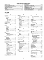
TABLE OF CONTENTS
SAFETY RULES ............................................................
2
PRODUCT SPECIFICATIONS ....................................... 3
CUSTOMER RESPONSIBILITIES
..................... 3, 15-18
WARRANTY ...................................................................
3
TABLE OF CONTENTS .................................................
4
INDEX ........................... ;.................................................
4
TRACTOR ACCESSORIES ........................................... 5
ASSEMBLY ..............................................................
7-10
OPERATION ...........................................................
11-t4
MAINTENANCE SCHEDULE ...................................... 15
SERVICE AND ADJUSTMENTS ............................ 19-24
STORAGE ....................................................................
25
TROUBLESHOOTING ............................................
26-27
REPAIR PARTS - TRACTOR ................................. 29-45
REPAIR PARTS - ENGINE ..................................... 46-50
PARTS ORDERING/SERVICE ................... BACK PAGE
INDEX
A
Accessories ................................................5
Adjustments;
Brake .............................................. 21
Carburetor. ................................... 24
Mower
Front-To-Back .............................20
Side-To-Side ..............................20
Throttle Control Cable ................ 24
Air Filter, Engine ....................................
17-18
Air Screen, Engine ................................. 18
Assembly ...............................................7-10
B
Battery:
Charging ......................................... 8
Cleaning ...... .................................. 16
Installation ...................................... 9
Levels ...............................................
8, t 7
Pr epar ation ........................................ 8
Starting with Weak Battery ........... 22
Storage ..............................................25
Terminals ............................................
16
Belts:
Motion Drive
Removal/Replacement
.......... 21
Mower Blade Drive
Removal!Replacement
........... 21
Blade:
Sharpening ........................................16
Replacement .................................. 16
Brake Adjustment ............................... 21
C
Carburetor Adjustment ........................ 24
Controls, Tractor ................................
11
Customer Responsibilities ........... 15-18
Engine:
Air Filter ................................. 17-I8
Foam Pre-Cleaner ................17-18
Air Screen, Engine .................... 18
Battery ................................... 16-17
Cooling Fins, Engine ..................18
Engine Oii ................................ 17
Fuet Filter .................................. 18
Spark Plugs ..................................18
Tractor:
Blade .......................................... 16
Lubrication Chart ..................... 15
Maintenance Schedule .......... 15
Tire Care .......................... 8,16,22
Cutting Height, Mower ......................... 12
E
O
Electrical:
Interlocks and Relays .................... 23
Schematic ........................................28
Wiring Diagram .............................. 30
Engine:
Air Filter .................................
t7-18
Foam Pre-Cleaner. ................... 17-18
Air Screen ...................................... 18
Cooling Fins, Engine ................... 18
Oil Change ..................................... 17
Oil Level ................................. 13,17
Oit Type ........................................ 17
Preparation ................................... 13
Repair Parts ............................. 46-50
Starting ........................................... 14
Storage ........................................... 25
F
Filter:
Air Filter ...................................... t7-18
Foam PreoCteaner. .................. 17-18
Fuel .............................................. 18
Fuek
Type ........................................
Storage .........................................
Fuse ...................................................
13
25
23
H
Hood Removal/Installation
.................. 23
L
Leveling Mower Deck ......................... 20
Lubrication Chart ................................... 15
M
Maintenance Schedule ....................... 15
Mower:
Adjustment, Front-to-Back ........... 20
Adjustment, Side-to-Side ............. 20
Blade Sharpening ........................... 16
Blade Replacement .........................16
Cutting Height .................................. 12
Installation .................................... 19
Operation .................................... 13
Removal ......................................
19
Mowing Tips ......................................... 14
Muffler ................................................
18
Spark Attester _.......................... 3,38
OIl:
Cold Weather Conditions .........13,17
Engine ............................................ 17
Storage ............................................ 25
Operation ............................................11-14
Operating Mower .................................. 13
Options:
Accessories .................................... 5
Spark Attester .......................... 3,38
P
Parking Brake .................................. 11-12
PartsBag .................................
6
Parts, Replacement!Repair.
...........29-45
Product Specifications ................................
3
R
Repair Parts ..............................
29-45
S
Safety Rules ................................................2
Seat ...............................................................8
Service and Adjustments ...............
19-24
Carburetor ..................................... 24
Fuse ............................................... 23
Hood Removal/installation
.......... 23
Motion Drive Belt
Removal/Replacement
............ 21
Mower Blade Drive Belt
Remova!/Replacement
........... 21
Mower Adjustment
Front- to-Back .......................... 20
Side*to-Side .............................. 20
Mower' Removal ............................. 19
Tire Care .................................8,16,22
Slope Guide Sheet ..........................
51
Spark Plugs ...............................
18
Specifications .............................
3
Starting the Engine ....................... 13-14
Steering Wheel ...............................
7,22
Stopping the Tractor .....................
12
Storage ..................................
25
T
Threttle
ControlCable Adjustment .....
24
3"ires.................................................. 8,16,22
Trouble Shooting Chart .................. 26-27
Transaxte Repair Parts ................
W
44-45
War ranty.................................
3
Wiring Diagram ................................
30
Wiring Schematic ............................
28
i,ii
illlllll
ii ii
iJi
lulll,
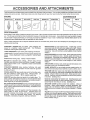
ACCESSORIES
............................
i,
lUll,
AND
iii ii
ATTAC
................
i
i l i,,
iiill
ENTS
, ...............
These accessories and attachments were available when the tractor was purchased, They are also available at most Sears retail outlets,
catalog and service centers. Most Sears stores can order these items for you when you provide the model number of your tractor_,
ENGINE
SPARK PLUG
MAINTENANCE
MUFFLER
AIR FILTER
GAS CAN
ENGINE OIL
STABILIZER
BLADES
BELT_
}
PERFORMANCE
Sears offers a wide variety of attachments that fit your tractor.
you, This list was current at the time of publication; however,
may be made in these attachments, or some may no longer
accessories and attachments
that are available for your
Many of these are listed below with brief explanations of how they can help
it may change in future years - more attachments may be added, changes
be available or fit your model, Contact your nearest Sears store for the
tractor.
Most of these attachments do not require additional hitches or conversion
attaching and detaching
PERMANEX
BAGGER lets you collect grass clippings and
teaves for a healthier, neater looking lawno Two Permanex
containers hold 30-gallon plastic bags.
LAWN SWEEPERS
let you collect grass clippings and leaves.
LAWN VACS for powerful collection of heavy grass clippings and
feaves
Wand attachment to pick up debris in hard-to-reach
pieces
CARTS make hauling easy, Variety of sizes available,
ROLLER for smoother Lawn surface,
36-inch wide, 18-inch
diameter water4ight drum holds up to 390 Ibs. of weight, Rounded
edges prevent harm to turf° Adjustable scraper automatically
cleans drum,
SPREADER/SEEDERS
make seeding, fertilizing, and weed
killing easy, Broadcast spreaders are also useful for granuiar
de.icers and sand
CORING AERATOR takes small plugs out of soil to allow moisture and nutrients to reach grass roots_ 36-inch swath. 24
hardened steel coring tips. 150 tbo capacity weight tray.
AERATOR promotes deep root growth for a healthy fawn. Tapered 2,5-inch steel spikes mounted on 104nch diameter discs
puncture holes in soil at close Intervals to let moisture soak in,
Steel weight tray for increased penetration.
MULCH RAKE/DETHATCHER
loosens soil and flips thatch and
matted leaves to lawn surface for easy pickup, Twenty spring tine
teeth, Useful to prepare bare areas for seeding. Available for front
or rear mounting.
SPRAYERS use 12welt DC electric motor that connects to the
tractor battery or other 12-volt source.
Includes booms for
automatic spraying when pulling, and hand held wand for spot
spraying, Wand has adjustable spray pattern. For applying
herbicides, Insecticides, fungicides, and liquid fertilizers,
kits (those that do are indicated) and are designed for easy
SNOW BLADE for snow removal only. 14-inch high, 42-inch
wide blade clears 38-inch path when angled left or right. Raises,
lowers with side lever_ Adjustable skids; replaceable, reversible
scraper bar (Use with tire chains, wheel weights, or rear drawbar
weight)
SNOWTH ROWER has 40-inch swath. Drum-type auger handles
powdery and wet!heavy snow, Mounts easily with simple pin
arrangement. Discharge chute adjusts from tractor seat° 64nch
diameter spout discharges snow 10 to 50 feet° Lift controlled at
tractor seat (Use with chains, wheel weights, or rear drawbar
weight.)
TIRE CHAINS are heavy duty; closely spaced extra-large cross
links give smooth ride, outstanding traction.
WHEEL WEIGHTS for rear wheels provide needed traction for
snow removal or dozing heavy materials. In pairs. (30 Ibs. each,)
TRACTOR CAB has heavy duty vinyl fabric over tubular steel
frame, ABS plastic top; clear plastic windshield offers 360 degree
visibility. Hinged metal doors with catch, Keeps operator warm
and dry, Remove vinyl and windshields for use as sun protector
in summon (Catalog only.)
Optional accessories
for tractor cab: tinted!tempered solid
safety glass windshield with hand operated wiper; 12-volt amber
caution light for mounting on cab top. (Catalog onlyo)
TRACTOR COVER protects tractor from weather.
Made of
Evolution 3 fabric (water-repellent, extremely breathable, light
weight, soft, non-abrasive, pliable in all temperatures, durable,
stalnitear/puncture resistant, will not shrink or stretch.) (Catalog
only.)
TILLER has 5 hp engine and 36-tnch swath to prepare seed beds,
cultivate, and compost garden residue. Tiller has Its own built-in
lift and depth control system and does NOT require a sleeve hitch.
Fits any lawn, yard, or garden tractor. Simply hook up to the
tractor drawbar and go!
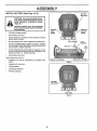
CONTENTS OF HARDWARE PACK
................
,
.....
...............
i
i
,
],,,i
mlnlll
H.
Parts Bag contents
........................
H
,H
"
,
shown
m,
i
,, i
................................
full size
i
n,,.uu
,unH
,i. ii
Parts
packed
i
separately
............................
in carton
,mu H.I
Seat
÷
(2) Sheet
Metal
Screws
#10-I6 x l/2
©
ufcher Plate
Steering
Boot
(1) Locknut 3/8-24
(1) Large Flat Washes
,,,,,,
Hu
,,,,,, H
Battery
Steering
Wheel
(1) Shoulder Bolt 5/16-18
(1) Hex Bolt 1/2-13 x 1
@
(1) Washer
mn m
Owner's
Manual
Parts Bag
..............
H,n,, H
Parts bag contents
....................
(1) Lock Washer
not shown
iii ii i i
i
m,,,u,
full size
i
rr ..............
1/2
17/32 x 1-3/16 x 12 Gauge
i
,,,,
H,,,nn
n ,i
_1
Wheel
teering
Insert
_(2)
Keys
Steering Wheel
Adapter
(1) Wing Nut 3/8
(1) Washer
3/32 x 1-1/4 x 16 Gauge
,,
i,,m,H
,nu ,n,mn
Steering
Bushing
1) Lock
Washer 3/8
n
. ....
(2) Hex Bolts ,(/--_
1/4-20 x 3/4 _.,('_2(2)
_1/4-20
Hex Nuts
i
...........
_)
(2) Washers
_
(2) Lock
Washers
1/4
L_
i
...............
Battery Caps
and Instructions
15 ° Slope Sheet
9/32 x 5/8 x 16 Ga.
nUl
,,
6
"HI
[.
,,n,u I
ASSSM
L¥
i i 1,1,11
ii
ii, iiii
Your new tractor has been assembled at the factory with exception of those parts left unassembled for shipping purposes,
To ensure safe and proper operation of your tractor, al_parts and hardware you assemble must be tightened securely. Use
the correct tools as necessary to insure their proper tightness.
TOOLS REQUIRED
FOR ASSEMBLY
A socket wrench set will make assembly easier. Standard
wrench sizes are listed.
(l) 5/16" wrench
(2) 7/16" wrenches
9/16" wrench
Screwdriver
(1) 1/2" wrench
Utility knife
(I) 3/4" wrench
Tire pressure gauge
TO REMOVE TRACTOR FROM CARTON
•
/./
3/8- 24 HEX LOCKNUT
(_.../2-1/4"
When right and left hand is mentioned in this manual, it
means when you are in the operating position (seated
behind the steering wheel)
UNPACK
INSERT'*__
DIA. WASHER
_
STEERING
STEERING
WHEEL
ADAPTER
_
_
STEERING
BUSHING
CARTON
Remove all accessible loose parts and parts cartons
from carton (See page 6)
•
Cut along lines on carton, from top to bottom, all four
corners of carton and lay panels flaL
°
Check for any additional loose parts or cartons and
remove
STEERING /
BOOT
(ASSEMBLY
POSITION)
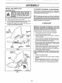
BEFORE ROLLING TRACTOR OFF SKID
ATTACH
STEERING
WHEEL
(See Fig. 1)
•
Slide the steering bushing over the steering shaft,
•
Raise steering shaft forward until screw holes in dash
line up with steering bushing_ Instalt two (2) sheet
metal screws and tighten securely,
•
Position steering boot over steering shaft,
•
Place tabs of steering boot over slots in dash and push
down to secure
•
Slidesteeringwheeladapteronto
•
Position front wheels of the tractor so they are pointing
straight forward
°
Position steering wheel so cross bars are horizontal
(left to right) and slide onto adapter,
•
Assemble large flat washerand 3/8-24 hexlocknut and
tighten securely.
•
Snap insert into center of steering wheel
uppersteeringshaft.
•
Remove protective plastic from tractor hood and grill
IMPORTANT:
CHECK
FOR AND REMOVE
ANY
STAPLES IN SKID THAT MAY PUNCTURE TIRES WHERE
TRACTOR IS TO ROLL OFF SKID
(See Fig. 8)
•
Raise attachment lift lever to its highest position.
•
Release parking brake by depressing
pedal
,
•
Place gearshift lever in "NEUTRAL" position.
Rclt tractor backwards off skid
•
Remove banding holding discharge guard up against
tractor
clutch/brake
STEERING
SHAFT
(SHIPPINGPOSITION)
FIG. 1
WHEEL
SCREW
ASSEMBLY
1,1,111
HOW TO SET UP YOUR
PREPARE
BATTERY
..................
iii
Adjust seat before tightening adjustment bolt.
(See Fig. 2)
.
Place seat on pan and assemble shoulder bolt.
Wash hands or clothlng Immediately If
accidentally in contact with battery acid.
•
Assemble adjustment bolt, lock washer and flat washer
loosely. Do not tighten=
Do not smoke. Fumes from charged
battery acid are explosive.
Read the instructions included with the
batteryventcaps.
Alwayswear gloves,
clothing and goggles to protect your
hands, skin and eyes.
•
Tighten shoulder boJtsecurely,
i,i,i, i ,i
IHlIHlll
I
II
Your tractor has a battery charging system which is sufficient for normal use, However, periodic charging of the
battery with an automotive charger wifl extend its life,
•
See instructions packed with vent caps in parts bag,
•
Fill battery with acid. Fill each ceil until it reaches the
bottom of the vent wells. Do not overfill.
•
Allow battery to stand arrd settle for at least thirty
minutes. After standing, check the level of acid. If
below the vent wells, add more acid until the correct
_evel is reached_
•
Lower seat into operating position and sit on seat,
.
Slide seat until a comfortable position isreached which
allows you to press clutch/brake pedal all the way down
(See Figv 6),
.
Get off seat without moving its adjusted position.
•
Raise seat and tighten adjustment bolt securely.
SEAT
SEAT PAN
SHOULDER
BOLT
While battery is standing (after adding acid) and later, while
battery is being char ged, contin ue with assembly of tractor.
IMPORTANT:
TO MAXIMIZE THE LIFE OF YOUR
BATTERY, IT IS NECESSARY THAT THE BATTERY BE
CHARGED
BEFORE USE FAILURE TO CHARGE
BATTERY CAN RESULT IN A SHORTENED BATTERY
LIFE.
•
Charge battery at a rate of 6 amperes for 1 hour. Use
a 12 voJtbattery charger. Observe all safety precautions
required for battery char ging.
Check the acid tevef after the battery is charged, if the
acid has fallen below the correct level, add distilled or
iron free water.
Install the vent caps to cover the vent weIIs, Wash the
top of the battery with water to remove any acid, then
wipe dry.
•
Check battery case for leakage to make sure that no
damage has occurred in handling.
•
Dispose of excess battery acid. Neutralize acid for
disposal by adding it to four inches of water in a five
gallon plastic container, Stir with a wooden or plastic
paddle while adding baking soda until the addition of
more soda causes no more foaming.
•
Remove cardboard packing on seat pan.
CAUTION'. Wear eye and face shield.
.......
•
i,
INSTALL SEAT (See Fig. 3)
TRACTOR
•
•
.......................
Follow instructions on how to install battery.
CUT AWAY VIEW
/
VENT CAP
_//VENT
WELL
BATTERY
CELL ACID
LEVEL
FIG. 2
FLAT WASHER
/
ADJUSTMENT
BOLT
• LOCK WASHER
FIG. 3
CHECK
TIRE PRESSURE
The tires on your unit were overinflated at the factory for
shipping purposes, Correct tire pressure is important for
best cutting performance.
•
Reduce tire pressure PSI shown in "PRODUCT
SPECIFICATION on page 3 of this manual,
CHECK
DECK
LEVELNESS
For best cutting results, mower housing should be properly
leveled.
See "TO LEVEL MOWER HOUSING
in the
Service and Adjustments section of this manual,
CHECK
BELTS
FOR
PROPER
POSITION
OF
ALL
See the figures that are shown for replacing motion and
mower btade drive belts in the Service and Adjustments
section of this manual. Verify that the belts are routed
correctly,
CHECK
BRAKE
SYSTEM
After you learn how to operate your tractor, check to see
that the brake is properly adjusted. See 'TO ADJUST
BRAKE" in the Service and Adjustments section of this
manual
ASSEMBLY
INSTALL
BATTERY
(See Figs. 4 & 5)
BATTERY
BOX DOOR
CAUTION: Do not short battery terminals. Before installing battery, remove
A
i
rings, etc.
etal bracelets, wristwatch bands,
Positive terminal must be connected
first to prevent sparking from accidental grounding.
ii
,i, ,,i1,11,
POSITIVE
(RED)
"_"
CABLE
i ,,,111
•
Lift seat to raised position.
•
Open battery box door,
•
Lower battery into battery box with battery terminals
toward front of tractor.
•
Be sure battery drain tube is attached to battery box,,
•
First connect RED battery cable to positive (+) battery
terminal with hex bolt, flat washer, lock washer and hex
nut as shown, Tighten securely,
•
Connect BLACK grounding cable to negative (.) battery terminal with remaining hex bolt, flat washer, lock
washer and hex nut. Tighten securely.
•
Close battery box door,
NEGATIVE
(BLACK)
CABLE
LOCK WASHER
FLAT
WASHER
HEX
BOLT
Open battery box door for:
•
inspection for secure connections
ware).
•
Inspection for corrosion.
•
Testing battery.
•
Jumping (if required),
•
Periodic charging.
(to tighten hard-
i
POSITIVE (+) TERMINAL
NEGATIVE
FIG, 4
BATTERY
VENT CAPS
FIG. 5
(-) TERMINAL
i,
,i,i
i,i, i, i1,, i
ii1,,-,,,,,,,,,
H,II,,
ii
ASSEMBLY
'
INSTALL
,11,,
i,i..........
IViULCHER
iii i1,1
,i,i1,,,,,i,,,i,,
PLATE
,i i,ii ii
TO CONVERT TO BAGGING
(See Figs. 6 & 7)
O
Assemble flat washer, lock washer and wing nut to
mounting bolt and tighten securely.
OR DISCHARGING
NOTE: Ifdischarging or bagging results are unsatisfactory
with mulcher blades on mower, remove the mulcher blades
and install high performance discharging blades which are
available at Retail and Catalog stores (See MOWER in the
Repair Parts section of this manual).
Position alignment cup over rear baffle.
Pivot mulcher plate forward and hook on mounting bolt_
Be sure hang tab hooks top of deck opening
L
Simply remove mulcher plate and store in a safe place.
Your mower is now ready for discharging or installation of
optional grass catcher accessory
guard from mower. Raise and hold
guard when attaching mulcher plate
__
CAUTION:
and
allow itDo
to no'i"r'emove
rest on platedischarge
while in
i
..........
oPeratio n•
@ Raise and hold deflector' shield in the upright position
_)
_
,,"CHECKLIST
BEFORE YOU OPERA TE AND ENJOY YOUR NEW
TRACTOR,
WE WISH TO ASSURE
THAT YOU
RECEIVE THE BES T PERFORMANCE
AND SA TISFACTION FROM THIS QUALITY PRODUCT
O
PLEASE REVIEW THE FOLLOWING
MOUNTING
BOLT
DEFLECTOR
,/
CHECKLIST:
All assembiy instructions have been completed
€" No remaining loose parts in carton.
MULCHER
PLATE
,/
Batteryis properly prepared and charged
t hour at 6 amps).
(Minimum
v"
Seat is adjusted comfortably and tightened securely
v_ All tires are properly inflated. (For shipping purposes,
the tires were overlnflated at the factory).
REAR
BAFFLE
ALIGNMENT
CUP
FASTING
TAB SLOT
Be sure mower deck is properly leveled side-to-side/
front-to-rear for best cutting results. (Tires must be
properly inflated for leveling)
v"
Check mowerand drive belts. Be sure they are routed
properly around pulleys and inside all belt keepers.
Check wiring. See that all connections are still secure
and wires are properly clamped.
v"
FIG, 6
DEFLECTOR
SHIELD
,,/
WHILE LEARNING HOW TO USE YOUR TRACTOR, PAY
EXTRAA TTENTION TO THE FOLL OWING IMPORTANT
ITEMS:
_-_
FLAT
LOCK
WASHER
HANG
MULCHER
PLATE
WINGNUT
FIG. 7
10
v"
Engine oi_ is at proper level.
v"
Fuel tank is filled with fresh, clean, regular unleaded
gasoline_
,,/
Become famiiiar with all controls - their location and
function. Operate them before you start the engine.
€"
Be sure brake system is in safe operating condition.
OPEF ATIO
....
,,
,,,,,,,,,,,,,,
,,,,,
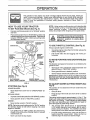
KNOW YOUR TRACTOR
READ THIS OWNER'S
MANUAL
AND SAFETY
RULES
BEFORE
OPERATING
YOUR TRACTOR
Compare the illustrations with your tractor to familiarize yourselfwith the locations of various controls and adjustments. Save
this manual for future reference.
A'I'FACNM ENT
CLUTCH LEVER
IGNITION
SWITCH
LiFT LEVER
PLUNGER
ATTACHMENT
LIFT LEVER
LIGHT SWITCH
THROTTL_CHOKE
CLUTCH/BRAKE
MOWER DECK
HEIGHT ADJUSTMENT
POSITIONS
PARKING
GEARSHIFT
LEVER
FIG. 8
Sears tractors conform to the safety standards of the American National Standards Institute.
ATTACHMENT CLUTCH LEVER: Used to engage the
mower blades, or other attachments mounted to your
tractor.
GEARSHIFT LEVER: Selects the speed and direction of
tractor°
ATTACHMENT LIFT LEVER: Used to raise, lower, and
adjust the mower deck or other attachments mounted to
your tractor.
LIFT LEVER PLUNGER: Used to release attachment lift
lever when changing its position.
LIGHT SWITCH: Turns the headlights on and off.
THROTTLE/CHOKE
CONTROL:
Used for starting and
controlling engine speed.
CLUTCH/BRAKE
PEDAL:
Used for declutching and
braking the tractor and starting the engine.
PARKING BRAKE: Locks clutch/brake pedal into the
brake position.
IGNITION SWITCH:
engine_
11
Used for starting and stopping the
OPERATION
The operation of any tractor can result in foreign objects thrown into the eyes, which can
result in severe eye damage. Always wear safety glasses or eye shields while operating
your tractor or performing any adjustments or repairs. We recommend wide vision safety
mask for over the spectacles or standard safety glasses, available at Sears Retail or
Catalog stores.
HOW TO USE YOUR TRACTOR
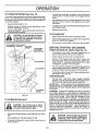
TO SET PARKING
•
BRAKE
NOTE: Under certain conditions when unit is standing idle
with the engine running, hot engine exhaust gases may
cause "browning" of grass. To eliminate this possibility,
always stop engine when stopping unit on grass areas.
(See Fig. 9)
Depress clutch/brake pedal into full "BRAKE" position
and hold.
L
Place parking brake lever in "ENGAGED" position and
release pressure from clutch/brake pedal. Pedal should
remain in "BRAKE" position. Make sure parking brake
will hold tractor' secure.
ATTACHMENT CLUTCH
"ENGAGED" POSITION
LEVER
CAUTION: Always stop unit completeiy'
k
as described above, before leavlngthe
_
operator's position; to empty grass
=_ catcher, etc.
I
_
a
"DISENGAGED
=
POSITION
TO USE THROTTLE
IGNITION KEY
CONTROL
(See Fig. 9)
Always operate engine at full throttle,
THROTTLE/
CHOKE
CONTROL
LEVER-
PARKING
BRAKE
"ENGAGED"
POSITEON
I
V
/
.
,
Start tractor with clutch/brake pedal depressed
gearshift lever in NEUTRAL position_
•
Move gearshift leverto desired position.
and
TO ADJUST MOWER CUTTING HEIGHT (See
Fig° 8)
The position of the attachment
cutting height,
Move attachment clutch lever to "DISENGAGED"
sition.
po-
Depress clutch/brake pedal into full "BRAKE" position.
lift lever determines
the
•
Grasp lift lever.
o
Press plunger with thumb and move lever to desired
position.
The cutting height range is approximately 1-1/2 to 4". The
heights are measured from the ground to the blade tip with
the engine not running, These heights are approximate
and may vary depending upon soi! conditions, height of
grass and types of grass being mowed.
position.
Move throttle control to "SLOW" position.
NOTE: Failure to movethrottte controlto "SLOW" position
and allowing engine to idle before stopping may cause
engine to "backfire".
•
•
•
Slowly release clutch/brake pedal to start movement.
IMPORTANT; BRING TRACTOR TO A COMPLETE STOP
BEFORE SHIFTING OR CHANGING GEARS_ FAILURE
TO DO SO WILL SHORTEN THE USEFUL LIFE OF YOUR
TRANSAXLEo
PARKING BRAKE
"DISENGAGED"POSITION
lever to"NEUTRAL"
(See
The direction and speed of movement is controlled by the
gearshift lever_
(See Fig. 9)
° Move gearshift
ENGINE -
AND BACKWARD
LEVER
GROUND DRIVE
•
Full throttle offers the best bagging and mower performance_
GEAR-
MOWER BLADES •
•
Fig. 8)
FIG, 9
STOPPING
Operating engine at less than full throttle reduces the
battery charging rate.
TO MOVE FORWARD
"BRAKE"
POSITION
CLUTCH/BRAKE
PEDAL "DRIVE" POSITION
•
Turn ignition key to "OFF" position and remove key.
Always remove key when leaving tractor to prevent
unauthorized use.
Never use choke to stop engine.
12
.
The average lawn should be cut to approximately
2-1/2 inches during the cool season arrd to over3
inches during hot months° For healthier and better
looking lawns, mow often and after moderate growth=
•
For best cutting performance, grass over 6 inches in
height should be mowed twice. Make the first cut
relatively high; the second to desired height,
OPERATION
TO OPERATE
MOWER
(See Fig, 10)
•
Yourtractorisequippedwithanoperatorpresencesensing
switch, Any attempt by the operator to leave the seat with
the engine running and the attachment clutch engaged will
shut off the engine
•
Select desired height of cut
•
Engage mower by slowly moving attachment clutch
lever to "ENGAGED" position_
TO STOP MOWER- Move attachment clutch lever to
"DISENGAGED" position,
•
.
If stopping is absolutely necessary, push clutch/brake
pedal quickly to brake position and engage parking
brake
Move gearshift Iever to 1st gear and be sure you have
allowed room for tractor to roll slightly as you restart
movement°
°
•
Torestartmovement,
slowlyreteaseparkingbrakeand
clutch/brake pedal
Make all turns slowly°
TO TRANSPORT
without either the entire grass catcher,
CAUTION:
operate or
thethe
mower
on
mowers Do
so not
equipped,
discharge guard in place.
ATTACHMENT CLUTCH LEVER
"DISENGAGED"
POSITION
,ENGAGED
POSITION
_
•
Raise attachment lift control to highest position
•
When pushing ortowing yourtractor,
lever is in NEUTRAL position°
.
Do not push or tow tractor at more than five (5) MPH
BEFORE STARTING
ATTACHMENT
LIFT LEVER
HIGH POSITION
CHECK
tt_
THE ENGINE
OIL LEVEL (See Fig, 16)
•
The engine in your tractor has been shipped from the
factory already filled with summer weight oil
•
Check engine oil with tractor on level ground.
•
Remove oil fill dipstick and wipe clean, replace and
screw cap tight, wait for a few seconds, remove and
read oil level. If necessary, add oil until "FULL" mark
on dipstick is reached_ Do not overfill
•
For cold weather operation you should change oil for
easier starting (see "OIL VISCOSITY CHART" in the
Customer Responsibilities section of this manual)_
•
To change engine oil, seethe Customer Responsibilities section in this manual
LOW POSITION
,
ENGINE
be sure gearshift
R,H. RUNNER
ADD GASOLINE
•
Fill fuel tank, Use fresh, clean, regular unleaded
gasoline_ (Use of leaded gasolinewitl increase carbon
and lead oxide deposits and reduce valve life).
IMPORTANT:
WHENOPERATINGINTEMPERATURES
BELOW 32°F(0°C), IJSE FRESH, CLEAN WINTER GRADE
GASOLINE TO HELP INSURE GOOD COLD WEATHER
STARTING
/
_
DISCHARGE
GUARD
WARNING:
Experience indicates that alcohol blended
fuels (called gasohol or using ethanol or methanol) can
attract moisture which leads to separation and formation of
acids during storage
Acidic gas can damage the fuel
system of an engine while in storage. To avoid engine
problems, the fuel system should be emptied before storage of 30 days or longer, Drain the gas tank, start the
engine and let it run until the fuel lines and carburetor are
empty. Use fresh fuel next season. See Storage Instructions for additional information.
Never use engine or
carburetor cleaner products in the fuel tank or permanent
damage may occur.
FIG. 10
TO OPERATE ON HILLS
hills with slopes greater than 15 ° and
CAUTION:
Do not drive up or down
do not drive across any slope°
"
Choose the slowest speed before starting up or down
hills_
°
Avoid stopping or changing speed on hills
o
If slowing is necessary, move throttle contro! lever to
slower position,
filler neck, Do not overfill. Wipe off any
CAUTION:
bottom
of gas
tank
spilled
oil orFill
fuel.to Do
not store,
spill
or
use gasoline near an open flame.
13
__
,=, ,,= ,n ,==,===
in=n!n.n .................
OPERATION
= 1,1! 1,1 ,11,1,11, , ==,,i.........................................
TO START
ENGINE
(See Fig. 9)
•
When mowing large areas, start by turning to the right
so that clippings will discharge away from shrubs,
fences, driveways, etc, After one or two rounds, mow
in the opposite direction making left hand turns until
finished (See Fig. 11),
•
If grass is extremely tall, it should be mowed twice to
reduce toad and possible fire hazard from dried clippings, Make first cut relatively high; the second to the
desired heighL
Do not mow grass when it is wet. Wet grass will plug
mower and leave undesirable clumps. Allow grass to
dry before mowing,
When starting engine for the first time or if engine has run
out of fuel, it will take extra cranking time to move fuel from
the tank to the engine,
•
.
•
•
•
Depress the clutch/brake pedal and set the parking
brake,
Place gearshift lever in "NEUTRAL" position,
Move attachment clutch to "DISENGAGED" position,
•
Move throttle control lever to "CHOKE" position for
cold engine starL. For warm engine start, move throttle
control to' FAST position
Turn ignition key clockwise to "START" position and
release key as soon as engine starts. Do not run
starter continuously for more than fifteen secends per
minute, if engine does no! start after severalatternpts,
move throttle control to FAST" position, wait a few
minutes and try again.
•
When engine starts, move throttle centrol to desired
position.
•
Allow engine to warm up for a few minutes before
engaging drive or attachment crutch.
•
Always operate engine at full throttie when mowing to
assure better mowing performance and proper discharge of material, Regulate ground speed byselecting a tow enough gear to give the mower cutting
performance as well as the quality of cut desired.
.
When operating attachments, select a ground speed
that wit! suit the terrain and give best performance of
the attachment being used.
MULCHING
MOWING
TIPS
IMPOR'rANT:
FOR BEST PERFORMANCE,
KEEP
MOWER HOUSING FREE OF BUILT-UP GRASS AND
TRASH, CLEAN AFTER EACH USE,
NOTE, If at a high altitude (above 3000 feet) or in cold
temperatures (below 32 ° F), the carburetor fuel mixture
may need to be adjusted for best engine performance. See
"TOAD JUST CARBURETOR" in the Service and Adjustments section of this manual
•
The special mulching blade will recut the grass clippings many times and reduce them in size so that as
they fall onto the lawn they wilt disperse into the grass
andnot be noticed, Also, the mulched grass wilt
biodegrade quickly to provide nutrients for the lawn.
Always mulch with your highest engine (blade) speed
as this will provide the best recutting action of the
blades,
•
Avoid cutting your lawn when it is wet, Wet grass tends
to form clumps and interferes with the mulching action.
The best time to mow your lawn is the early afternoon,
At this time the grass has dried and the newly cut area
will not be exposed to the direct sun.
IVIOWING TIPS
'
Tire chains cannot be used when the mower housing
is attached to tractor,
.
Mower should be properly leveled for best mow!ng
performance. See"TO LEVEL MOWER HOUSING in
the Service and Adjustments section of this manual.
•
Use the runner on the right hand side of mower' as a
guide° The blade cuts approximately an inch outside
the runner (See Fig, 10).
The left hand side of mower should be used for trimruing,
°
Drive so that clippings are discharged onto the area
that has been cut. Have the cut area to the right of the
tractor, This will result in a more even distribution of
clippings and more uniform cutting,
For best results, adjust the mower cutting height so that
the mower cuts offenly the top oneothird of the grass
blades (See Fig, 12). For extremely heavy mulching,
reduce your width of cut and mow slowly.
•
Certain types of grass and grass conditions may require that an area be mulched a second time to completely hide the clippings° When doing a second cut,
mow across or perpendicular to the first cut path.
•
Change your cutting pattern from week to week. Mow
north to south one week then change to eastto west the
next week_ This will help prevent matting and graining
of the lawn.
•
,
MAX 1/3
FIG. 11
FIG. 12
14
MAINTENANCE
SCHEDULE
AS YOUCOMPLETE
REGULAR
SERVICE
/__/S_
_O_,
__ERVICE
Check
Brake Operation
6# 4
Check
Tire Pressure
V"
T
Check
for Loose Fasteners
V"
AR
Sharpen/Replace
Mower
_
Battery
LeveltRecharge
0
Clean
Battery
and Terminals
R
'Check Transmission
Blade
Adjust
Morton
Drive Belt(s)
Check
Engine
Oil Level
Change
E
N
Clean
Belt(s)
Engine
inspect
I
Replace
DATES
v"
v,
M_
MY"
V"
Tension
"_i
#'-
Oil
Air Filter
::
Muffler/Spark
Oil Filter
I_
Arrester
(if equipped)
'Cl;anEr;'g'i_;;
Coo,ng
Fine
Replace
Spark
Replace
Air Filter
Replace
Fuel FiJter
Plug
. _
__V___V"
____
Paper Cartridge
v'
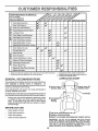
1. Change more often when operating under a heavy toad or In high ambient temperatures
2 - Service more often when operating In dirty or dusty conditions
GENERAL
_-_..£O".
Tension
Clean Ai r Screen
G
_'_
My'
Cooling
Adjust
.£',_
V"
Blades
Check
,G_,_.
v"
C _bricat_-_h-art
T
_
3 - If equtpped with oll filter, changeoil every 50 hours
4 - Replace blades more often when mowing In sandy soil
5 - if equippedw_thadjustablesystem
LUBRICATION
RECOMMENDATIONS
The warranty on this tractor does not cover items that have
been subjected to operator abuse or negligence_ To
receive full value from the warranty, operator must maintain
tractor as instructed in this manual.
CHART
(_)
BEARING
" FRONT WHEEL(_)
BEARING ZERK
ZERK
Some adjustments will need to be made periodically to
properly maintain your tractor,
All adjustments in the Service and Adjustments section of
this manual should be checked at least once each season.
ENGINE(_)
Once a year you should replace the spark plug, clean
or replace air filter, and check blades and belts for
wear. A new spark plug and clean air filter assure
proper air-fue! mixture and help your engine run better
and last longer.
BEFORE
EACH
®
CLUTCH
PIVOT(S)
USE
•
Check engine oil level,
•
Check brake operatlon_
(_) SAE 30 OR 10W30 MOTOR OIL API - SG
•
•
Checktire pressure,
Check for loose fasteners,
(_) GENERAL
_)
PURPOSE GREASE
REFER TO CUSTOMER
RESPONSIBILITIES
"ENGINE"
SECTION
IMPORTANT:
DO NOT OIL OR GREASE THE PIVOT POINTS
WHICH HAVE SPECIAL NYLON BEARINGS°
VISCOUS
LUBRiCANTS WILL ATTRACT
DUST AND DIRT THAT WILL SHORTEN
THE LIFE OF THE SELF-LUBRICATING
BEARINGS.
IF YOU
FEEL THEY MUST BE LUBRICATED,
USE ONLY A DRY, POWDERED GRAPHITE
TYPE LUBRICANT
SPARINGLY.
15
i
CUSTOMER
,
i
u
.......
RESPONSIBILmES
TRACTOR
Always observe
nance,
ii
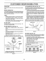
TO SHARPEN BLADE (See Fig. 15)
safety rutes when performing
Care should be taken to keep the biade balanced. An
unbalanced blade wilt cause excessive vibration and eventual damage to mower and engine.
any mainte-
BRAKE OPERATION
If unit requires more than six (6) feet stopping distance at
high speed in highest gear, than brake must be adjusted.
(See "TO ADJUST BRAKE" in the Service and Adjustments section of this manual)=
TIRES
•
Maintain proper air pressure in all tires (See "PRODUCT SPECIFICATIONS" on page 3 of this manual)°
•
Keep tires free of gasoline, oil, or insect control chemicals which can harm rubber_
•
Avoid stumps, stones, deep ruts, sharp objects and
other' hazards that may cause tire damage.
•
The blade can be sharpened with a file or on a grinding
wheel. Do not attempt to sharpen while on the mower.
•
To check blade balance, you wilt need a 5/8" diameter
steel bolt, pin, or a cone balancer. (When using a cone
balancer, follow the instructions supplied with balanGer).
•
Slide blade on to an unthreaded portion of the steel bolt
or pin and hold the bolt or pin parallel with the ground.
If blade is balanced, it should remain in a horizontal
position. If either end of the blade moves downward,
sharpen the heavy end until the blade is balanced.
NOTE: Do not use a nail for balancing blade. ]'he lobes of
the center hole may appear to be centered, but are not.
CENTER
BLADE CARE
HoLE
For best results mower blades must be kept sharp_ Replace bent or damaged blades°
BLADE REMOVAL
BLADE
(See Fig. 14)
•
Raise mower to highest position to allow access to
blades_
•
Remove hex bolt, lock washer and flat washer securing
blade.
•
Install new or resharpened blade with trailing edge up
towards deck as shown.
°
Reassemble hex bolt, lock washer and flat washer in
exact order as shown°
518"BOLT
OR PiN
FIG. 15
BATTERY
(See Fig. 16)
Your unit has a battery charging system which is sufficient
for normal use° However, periodic charging of the battery
with an automotive charger will extend its lifeo
•
Tighten bolt securely (30-35 Ft. Lbs. torque).
IMPORTANT; BLADE BOLT IS GRADE 8 HEATTREATED.
MANDREL
TRAlUNG
EDGEUP
•
Acid solution level in each battery cell should be even
with bottoms of vent wells. Add ontydistilled or iron free
water if necessary. Do not overfill
°
•
Keep battery and terminals clean.
Keep battery bolts tight.
•
•
Keep vent caps tight and small vent holes in caps open.
Recharge at 6 amperes for 1 hour.
CUTAWAYVIEW
FLAT WASHER
I
1/VENTCAP
I
!
LOCKWASHER
WELL
HEXBOLT
(GRADEe)
CELL ACID
LEVEL
'A GRADE 8 HEAT TREATED BOLT CAN BE IDENTIFIED BY
SIX UNES ON THE BOLT HEAD.
FIG, 16
FIG. 14
16
CUSTO
ILITmES
RESPON
TO CLEAN BATTERY AND TERMINALS
_
Corrosion and dirt on the battery and terminals can cause
the battery to "leak" power.
•
Remove terminal guard.
•
Disconnect BLACK battery cable first then RED battery cable and remove battery from tractor,
•
Wash battery with solution of four tablespoons of
baking sodato one gallon of water, Be careful notto get
the soda solution into the ceils.
•
After oil has drained completely, replace oil drain plug
and tighten securely.
•
Refill engine with oil through oil fill dipstick tube. Pour
slowly, Do not overfill, For approximate capacity see
Product Specifications on page 3 of this manual,
•
Use gauge on oil fill dipstick for checking level, Be sure
AIR SCREEN
•
Rinse the battery with plain water and dry.
ENGINE OIL
•
Clean terminals and battery cable ends with wire brush
until bright,
FILL TUBE
,
Coat terminals with grease or petroleum jelly,
•
Reinstall battery (See "INSTALL
Assembly section of this manual)
BATTERY"
in the
FIG. 17
V-BELTS
AIR SCREEN
Check V-belts for deterioration and wear after 100 hours
and replace if necessary, The belts are not adjustable.
Replace belts if they begin to slip from wear,
TRANSAXLE
(See Fig. 17)
The engine air screen must be kept free of dirt and chaff to
prevent engine damage from overheating, Clean with a
wire brush or compressed air to remove dirt and sutbborn
dried gum fibers.
COOLING
ENGINE
Keep transaxfe free from build-up of dirt and chaff which
can restrict cooling,
COOLING
FINS (See Fig. 18)
Remove any dust, dirt or oil from engine cooling fins to
prevent engine damage from overheating. Airguide covers
must be removed, Remove side panels and hood (See "TO
REMOVE HOOD AND GRILL ASSEMBLY" in the Service
and Adjustments section of this manual°
ENGINE
LUBRICATION
Only use high quality detergent oil rated with API service
classification SG, Select the oil's SAE viscosity grade
according to your expected operating temperature,
SAE VISCOSITY GRADES
1
°F
-20"
°C -30"
O"
_20_
30*
-10°
32*
0_
40 _
60 _
10_
80'
20'
100 _
30 _
CLEAN THESE AREAS OF DIRT AND DEBRIS
40"
TEMPERATURE RANGE ANTICIPATED BEFORE NEXT OIL CHANGE
FIG, 18
NOTE: Although multi-viscosity oils (5W30, 10W30 etc.
improve starting in cold weather, these multi-viscosity oils
will result in increased oil consumption when used above
32°F. Check your engine oil level more frequentlyto avoid
possible engine damage from running low on oil,
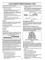
AIR FILTER (See Fig. 19)
Your engine will not run properly and may be damaged by
using a dirty air filter. Clean the foam pre-cteaner element
after every 25 hours of operation or every season, Service
paper cartridge every 100 hours or every season, whichever occurs first,, Service air cleaner more often under
dusty conditions.
Change the oil after the first two hours of operation and
every 25 hours thereafter or at least once a year if the
tractor is not used for 25 hours in one year,
•
Check the crankcase oil level before starting the engine
and after each eight {8) hours of continuous use, Tighten
oil fill cap/dipstick securely each time you check the oi!
level,
Unhook clips on both sides of air cleaner and remove
cover_
TO SERVICE PRE-CLEANER
-
•
Slide foam pre-cleaner off cartridge.
TO CHANGE ENGINE OIL (See Fig_ 17)
•
Be sure vehicle is on level surface
°
Wash it in liquid detergent and water,
°
Squeeze it dry in a clean cloth.
•
•
Oil wil! drain more freely when warm,
Catch oil in a suitable container,
•
Saturate it in engine oil, Wrap it in clean, absorbent
cloth and squeeze to remove excess oil,
•
Remove oil fill dipstick, Be careful not to allow dirt to
enter the engine when changing oil,
•
Reinstall pre-cleaner over cartridge,
°
•
Remove drain plug,
Reinstall air cleaner cover and reattach clips to sides of
air cleaner body,
17
..................................
iinulu u=uHuml"Hi
.....................................
CUSTOMER
RESPON
TO SERVICE CARTRIDGE •
Remove knob and cover plate,
BmL
ES
,
Install replacement oil fitter by turning clockwise untii
rubber gasket contacts mounting surface, then tighten
filter an additional 1/2 to 3/4 turn.
•
Remove cartridge and clean by tapping gently on flat
surface.
.
.
If very dirty, replace or wash in a nonsudsing detergent
and warm water solution. Rinse thoroughly with water
from inside out until water' runs ciear, Let cartridge dry
thoroughly before using
Fill crankcase with new oil (See "TO CHANGE ENGINE OIL"), For approximate capacity see "PRODUCT SPECIFICATIONS" on page 3 of this manual.
•
Start engine and check for oi! leaks. Correct any leaks
before placing engine into full operation.
•
Reinstall cartridge, cover plate, knob and pre-cleaner_
•
Reinstall air cleaner cover and reattach clips to sides of
air cleaner body.
IMPORTANT:
PETROLEUM SOLVENTS, SUCH AS
KEROSENE,
ARE NOT TO BE USED TO CLEAN
CARTRIDGE THEY MAY CAUSE DETERIORATION OF
THE CARTRIDGE. DO NOT OIL CARTRIDGE, DO NOT
USE PRESSURIZED
AIR TO CLEAN
OR DRY
CARTRIDGE.
/
OIL FILTER
FOAM PRE*
CLEANER
FIG. 20
IN-LINE
FUEL FILTER
(See Fig. 21)
Fuet filter should be replaced once each season, Iffuel filter
becomes clogged, obstructing fuel flow to carburetor, re_
placement is require&
KNOB
COVER
PLATE
.
With engine cool, remove filter and plug fuel line
sections.
°
Place new fuel filter in position in fuel line with arrow
pointing towards carburetor.
•
Be sure there are no fuel line leaks and clamps are
properly positioned,
-
Immediately wipe up any spilled gasoline.
CUP
CLAMP
CLAMP
FIG. 19
MUFFLER
Inspect and replace corroded muffler and spark arrestor (if
equipped) as it could create a fire hazard and/or damage.
SPARK PLUGS
FIG. 21
Replace spark plugs at the beginning of each mowing
season or after every t00 hours of use, whichever comes
first. Spark plug type and gap setting is shown in "PRODUCT SPECIFICATIONS" on page 3 of this manual.
CLEANING
•
Clean engine, battery, seat, finish, etc. of all foreign
matter.
ENGINE OIL FILTER (See Fig. 20)
•
Replace the engine oil filter every season or every other oi!
change if the tractor is used more than 100 hours in one
year.
Keep finished surfaces and wheels free of all gasoline,
oil, etc.
•
Protect painted surfaces with automotive type wax,
.
Unscrew old filter by turning counterclockwise, Use a
suitable container to catch oil,
•
Apply a thin coating of new engine oitto rubber gasket
on replacement oil fitter,
We do not recommend using a garden hose to clean your
unit unless the electrical system, muffler, air filter and
carburetor are covered to keep water out. Water in engine
can result in a shortened engine life,
18
SERVmCE AND ADJUSTMENTS
CAUTION:
o
BEFORE PERFORMING ANY SERVICE OR ADJUSTMENTS:
Depress clutch/brake pedal fully and set parking brake.
Place gearshift lever In "NEUTRAL" position.
Place attachment clutch In "DISENGAGED" position,
Turn Ignition key "OFF" and remove key.
Make sure the blades and all moving parts have completely stopped.
Disconnect spark plug wire from spark plug and place wire where It cannot come In contact with
plug.
iiii1,1,,,11,,111111,111
.................................
i
i
i
i
ii I
i
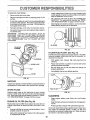
TRACTOR
TO REMOVE
MOWER
(See Fig. 20)
CLUTCH ROD
Mower will be easier to remove from the right side of tractor.
*
Place attachment clutch in "DISENGAGED"
•
Move attachment lift lever forward to lower mower to its
lowest position°
,
Roll belt off engine pulley.
*
Disconnect clutch rod from chJtch lever by removing
retainer spring.
RETAINER SPRING
position.
RETAINER
,
Disconnect anti-sway bar from chassis bracket
removing retainer spring.
*
Disconnect suspension arms from rear deck brackets
by removing retainer springs.
•
Disconnect front links from deck by removing retainer
springs.
RETAINER
SPRINGS
SPRINGS
by
ENGINE
PULLEY
•
Raise lift lever to raise suspension arms.. Slide mower
out from under tractor.
IMPORTANT:
IF AN ATTACHMENT OTHER THAN THE
MOWER IS TO BE MOUNTED TO THE TRACTOR, THE
R.H. AND L.H. SUSPENSION ARMS MUST BE REMOVED
FROM TRACTOR°
RETAINER
SPRING
ANTI-SWAY BAR
TO INSTALL MOWER (See Fig. 20)
•
Raise attachment lift lever to its highest position.
•
Slide mower under tractor with discharge guard to right
side of tractor.
•
•
Lower lift lever to its lowest position_
Install mower in reverse order of removal instructions°
FIG. 20
19
SERVnCE AND ADJUSTMENTS
J, ,uu,u
........................................................................................................
TO LEVEL
MOWER
HOUSING
Adjust the mower while tractor is parked on level ground or
driveway.
Make sure tires are properly inflated (See
"PRODUCTSPEClF1CATIONS"on
page3ofthis manual).
If tires are over or under inflated, you will not properly adjust
your mower°
SIDE-TO-SIDE ADJUSTMENT (See Fig& 21 and 22) You wilt need two (2) standard 2 x 4 short pieces of wood
to make the following adjustment. Simitar blocks measuring 1-1/2" thick may also be used.
•
Raise mower with attachment lift control to allow two
(2) 1-1/2" thick blocks to be placed under rear edge of
mower directly behind mandrels,
•
Lower mower deck to its lowest height of cut position
(See TO ADJUST MOWER CUTTtNG HEIGHT in the
Operation section of this manual).
•
On both sides of tractor, loosen, but do not remove, the
fasteners securing the adjustable pivot brackets to
chassis, Both brackets must be loose enough to move
freely,
•
Pull down firmly on suspension arm to remove any
slack in pivot bracket and hold while tightening rear
fastener first to secure. Tighten remaining fastener.
•
•
Repeat procedure on other side of tractor.
Raise mower with attachment lift control and remove
blocks from under mower.
i,
FRONT-TO-BACKADjUSTMENT
(See Figs. 23 and 24) IMPORTANT: DECK MUST BE LEVEL SIDE-TO-SIDE. IF
THE FOLLOWING FRONT-TO-BACK ADJUSTMENT IS
NECESSARY, BE SUR E TO ADJ UST BOTH FRONT LINKS
EQUALLY SO MOWER WILL STAY LEVEL SIDE-TOSIDE.
To obtain the best cutting results, the mower housing
should be adjusted so that the front is approximately 1/4" to
3/4" lower than the rear when the mower is in its highest
position.
Check adjustment on right side of tractor. Measure distance "D" directly in front and behind the mandrel at bottom
edge of mower housing as shown.
•
Before making any necessary adjustments, check that
both front links are equal in length. Both links should
be approximately t0-3/8",
•
If links are not equal in length, adjust one link to same
length as other link.
To lower front of mower loosen nut "E" on both front
links an equal number' of turns.
•
PLACE TWO (2) 1-1t2" THICK BLOCKS UNDER REAR EDGE OF
DECK (Use wood 2 x 4'a or equivalent)
•
When distance "D" is 1/4" to 3/4" lower at front than
rear, tighten nuts "F" against trunnion on both front
links°
•
To raise front of mower, loosen nut "F' from trunnion on
both front links° Tighten nut "E" on both front links an
equal number of turns.
•
When distance "D" is 1/4" to 3/4" lower at front than
rear, tighten nut"F" against trunnion on both front links°
•
Recheck side-to-side adjustment.
%_._
/o
o
° °! /MANDREL
FIG. 23
BOTH FRONT
MOWER MUST BE IN LOWEST
UNKS
MUST BE EQUAL IN LENGTH
HEIGHT OF CUT POSmON
FIG. 21
ADJUSTABLE
BRACKET
PIVOT
FASTENERS
'E'
NUT "F"_
NUT
PULL DOWN AND
TIGHTEN REAR
FASTENER FIRST
FRONr LINKS
FIG. 22
2O
TRUNNION
FIG. 24
,r,,,,1=,1
SERVICE AN
....
TO REPLACE
(See Fig. 25)
i
MOWER
.....
ii,
ADJUSTMENTS
,,,,i,1,1111 ,,,
BLADE DRIVE BELT
WITH PARKINGBRAKE"ENGAGED"
The mower blade drive belt may be replaced without
tools, Park the tractor on level surface, Engage parking
brake. For assistance, there is a belt installation guide
decal on the mower housing.
BELT REMOVAL •
Place attachment clutch in "DISENGAGED" position,
•
Move attachment lift lever forward to lower mower to
its lowest position.
°
Roll belt off engine pulley
•
Disconnect R.H. suspension arm from
bracket by removing retainer spring,
•
NUT "A"
rear deck
NUT
Work belt off both mandrel pulleys and idler pulleys
°
Pull beit away from mower,
BELT INSTALLATION ,
Install new belt in reverse order of removal
•
RATING
Make sure belt is in all pulley grooves and inside all
belt guides.
FIG. 26
TO REPLACE MOTION DRIVE BELT (See
MANDREL
IDLER
Fig, 27)
ENGINE PULLEY
Park the tractor on level area. Engage parking brake
For assistance, there is a belt installation guide decal on
bottom side of left footrest.
•
Remove mower (See "TO REMOVE MOWER" in this
section of this manual).
Remove upper belt keeper.
•
Remove belt from stationary idler and clutching idler
•
Pull belt slack toward rear of tractor_ Remove belt
upwards from transaxle pulley by deflecting belt
keepers.
•
Pull belt toward front of tractor and remove downwards from around engine pulley°
•
Install new belt by reversing above procedure.
IMPORTANT: MAKE SURE UPPER BELT KEEPER IS
POSITIONED PROPERLY BETWEEN LOCATOR TABS.
asH.
SION ARM
RETAINER
SPRING
MANDREL
PULLEY
ENGINE PULLEY",.
-LOCATOR
FIG. 25
TO ADJUST
BRAKE
CLUTCHING
IDLER
"_-'--_
UPPER
BELT
KEEPER
(See Fig. 26)
Your tractor is equipped with an adjustable brake system
which is mounted on the right side of the transaxle
TABS
STATIO NARY_--'-"
IDLER
If tractor requires more than six (6) feet stopping distance
at high speed in highest gear, then brake must be adjusted,
•
Depress clutch/brake pedal and engage parking brake
•
Measure distance between brake operating arm and
nut "A" on brake rod.
•
If distance is other than 1-1/2", disengage parking
brake, loosen jam nut and turn nut "A" until distance
becomes 1-1/2". Retighten jam nut against nut "A"o
•
Engage parking brake and recheck distance.
•
Road test tractor for proper stopping distance as stated
above, Readjust if necessary. If stopping distance is
still greater than six (6) feet in highest gear, further
maintenance is necessary Contact your nearest authorized service center,.
CHASSIS
TRANSAXLE
PULLEY
21
F|G. 27
I"IHII'H'I'IHI'
'1'"'
"11
"1
I '
'
I
SERVICE AN
ADJUSTMENTS
I
.....................................
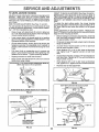
TO ADJUST
STEERING
WHEEL ALIGNMENT
TO START ENGINE
See Fig. 29)
if steering wheel crossbars are not horizontal (Ieft to right)
when wheels are positioned straightforward, remove steering wheel and reassemble per' instructions in the Assembly
section of this manual°
FRONT WHEEL
CAUTION:
TOE-IN/CAMBER
WHEEL
FOR REPAIRS
,i
,
,
,
WITH A WEAK
N
BATTERY
Lead-acid batteries gener-
and smoking materials away from batate explosive gases, Keep sparks, flame
teries,
Always wear eye protection
when around batteries°
HHH" 'HI
The front wheel toeJn and camber are not adjustable on
your tractoro Ifdarnage hasoccured to affectthe frontwheel
toe.in or camber, contact your nearest authorized service
center
TO REMOVE
ii
(See
Block up axle securely,
•
Remove axle cover, retaining ring and washers to allow
wheel removal (rear wheel contains a square key - Do
not lose).
•
Repair tire and reassemble_
•
On rear wheels only: align grooves in rear wheel hub
and axle. Insert square key,
•
Replace washers and snap retaining ring securely in
axle groove
•
Replace axle cover',
....
If your' battery is too weak to start the engine, it should be
recharged.
If "jumper cables" are used for emergency
starting, follow this procedure:
IMPORTANT:
YOUR UNIT IS EQUIPPED WITH A t2
VOLT NEGATIVE GROUNDED SYSTEM. THE OTHER
VEHICLE MUST ALSO BE A 12 VOLT NEGATIVE
GROUNDED SYSTEM. DO NOT USE YOUR TRACTOR
BATTERY TO START OTHER VEHICLES
Fig. 28)
•
I
TO ATTACH JUMPER CABLES .
Connect each end of the RED cable to the POSITIVE
(+) terminal of each battery, taking care not to short
against chassis.
•
Connect one end of the BLACK cable to the NEGATIVE (-) terminal of fully charged battery.
•
Connect the other end of the BLACK cable to a good
CHASSIS GROUND, awayfrom fuel tank and battery.
TO REMOVE CABLES, REVERSE ORDER •
•
BLACK cable first from chassis and fully charged
battery.
RED cable last from both batteries.
POSITIVE TERMINAL
WASHERS
NEGATIVE
TERMINAL
/
RETAINING
RING
!
AXLE COVER
_
SQUARE
KEY
(REAR WHEEL ONLY)
FIG. 28
CABLES
CHARGED
BATTERY
POSITIVE TERMINAL
NEGATIVE
FIG. 29
22
TERMINAL
===
SERVICE AND ADJUSTMENTS
ii
TO REPLACE
FUSE
(See Fig. 30)
TO REMOVE
HOOD
•
Raise hood,
Replace with 30 amp automotive.type piug4n fuse. The
fuse holder is located in the engine compartment, directly
in front of the dash
AND
GRILL
(See Fig. 31)
•
Unsnap headlight wire connector.
•
Stand in front of tractor, Grasp hood at sides, tilt
forward and lift off of tractor.
•
To reinstall_ slide hood pivot brackets into slots in
frame. Replace retainer springs,
°
Reconnect headlight wire connector and close hood.
HOOD
FUSE
HOLDER
HEADLIGHT WIRE
CONNECTOR
FIG. 30
TO REPLACE
HEADLIGHT
BULB
•
Raise hood,
•
Pull bulb holder out of the hole in the backside of the
grill
•
Replace bulb in holder and push bulb holder securely
back into the hole in the backside of the grill
Close hood,
•
INTERLOCKS
AND
RELAYS
FIG. 31
Loose or damaged wiring may cause your tractor to run
poorly, stop running or prevent it from starting.
•
Check wiring, See the electrical wiring diagram in the
Repair Parts section of this manual,
23
i
,ll .....
i
= =
i
i,,i,ill,,i
....
i
,,=l
,,l= ....................
ill,,
SSRWCE AND ADJUSTMENTS
=
= H=HHHI, ,,,q=,,,
ENGINE
TO ADJUST THROTTLE
(See Fig. 32)
FINAL SETTING -
CONTROL
CABLE
The throttle control has been preset at the factory and
adjustment should not be necessary. Check adjustment as
described below before loosening cable. If adjustment is
necessary, proceed as follows:
*
With engine no! running_,move throttle control lever
from "SLOW" to 'CHOKE position. Slowly move lever
from "CHOKE" to "FAST" position°
*
Checkthat holes"A" in governor control lever and hole
in governor plate line_up. If holes "A" are not aligned,
loo sen cramp screw and move throttle cable until holes
are aligned. Tighten clamp screw securely°
•
Start engine and allow to warn} for five minutes. Make
final adjustment, s with engine running and shift/motion
control lever in NEUTRAL' position.
•
Move throttle control lever to "SLOW" joosition_ With
finger, rotate and hold throttle lever against idle speed
screw. Turn idle speed screw to attain 1750 RPM_
,
While still holding throttle lever' against idle speed
screw, turn idle mixture valve in (clockwise) until engine begins to die and then turn out (counterclockwise)
until engine runs rough. Turn valve to a point midway
between those two positions_ Release throttle lever.
ACCELERATION
•
GOVERNOR
CONTROL LEVER
GOVERNOR
CONTROL PLATE
TEST -
Move throttle control lever from "SLOW" to "FAST"
position, If engine hesitates or dies, turn idle mixture
valve out (counterclockwise) 1/8 turn. Repeat test and
continue to adjust, if necessary, until engine accelerates smoothly.
High speed stop is factory adjusted.
damage may result.
Do not adjust -
IMPORTANT:
NEVER TAMPER WITH THE ENGINE
GOVERNOR, WHICH IS FACTORY SET FOR PROPER
ENGINE SPEED. OVERSPEEDING THE ENGINE ABOVE
THE FACTORY HIGH SPEED SETTING
CAN BE
DANGEROUS. IF YOU THtNKTHE ENGINE-GOVERNED
HIGH SPEED NEEDS ADJUSTING, CONTACT YOUR
NEARESTAUTHORtZED SERVICE CENTER, WHICH HAS
PROPER EQUIPMENTAND EXPERIENCE TO MAKE ANY
NECESSARY ADJUSTMENTS.
HOLES=A"
CLAMP
SCREW
THROTTLE
CABLE
FIG. 32
TO ADJUST CARBURETOR
THROTTLE
LEVER
(See Fig. 33)
IDLE SPEED
SCREW
The carburetor has been preset at the factory and adjustment should not be necessary. However, minor adjustment may be required to compensate for differences infuel,
temperature, altitude or load. tf the carburetor does need
adjustment, proceed as follows:
in general, turnig idle mixture valve in (clockwise) decreases the supply of fuel to the engine giving a leaner fuel/
air mixture. Turning the idle mixture valve out (counterclockwise) increases the supply of fuel to the engine giving
a richer fuel/air mixture.
IMPORTANT; DAMAGE TO THE NEEDLE VALVE AND
THE SEAT IN CARBURETOR MAY RESULT tF SCREW iS
TURNED IN TOO TIGHT.
PRELIMINARY SETTING ,
Air cleaner assembly must be assembled to the carburetor when making carburetor adjustments.
•
Be sure the throttle control cable is adjusted properly
(see above),
IDLE MIXTURE
VALVE
•
With engine off turn idle mixture valve in (clockwise)
closing it finger tight and then turn out (counterclockwise) 1 full turn.
FIG, 33
24
Immediately prepare your tractor for storage at the end of
the season or ifthe unit will not be used for 30 days or more.
CAUTION:
ENGINE
FUEL SYSTEM
IMPORTANT:
IT tS IMPORTANT TO PREVENT GUM
DEPOSITS FROM FORMING IN ESSENTIAL FUEL
SYSTEM PARTS SUCH AS CARBURETOR, FUEL FILTER.
FUEL HOSE, OR TANK DURING STORAGE,
ALSO.
EXPERIENCE INDICATES THAT ALCOHOL BLENDED
FUELS (CALLED GASOHOL OR USING ETHANOL OR
METHANOL) CAN ATTRACT MOISTURE WHICH LEADS
TO SEPARATION AND FORMATION OF ACIDS DURING
STORAGE.
ACIDIC GAS CAN DAMAGE THE FUEL
SYSTEM OF AN ENGINE WHILE IN STORAGE,
Never store the tractor with
where
fumes
may
reach
an open
flame
gasoline
in the
tank
inside
a building
or spark. Allow the engine to cool
before storing in any enclosure.
TRACTOR
•
Drain the fuel tank.
Remove mower from tractor for winter storage, When
mower is to be stored for a period of time, clean it thoroughly, remove all dirt, grease, leaves, etco Store in a
clean, dry area.
o
Start the engine and let it run until the fuel lines and
carburetor are empty.
•
Never use engine or carburetor cleaner products in the
fuel tank or permanent damage may occur.
Use fresh fuel next season
o
Clean entire tractor (See "CLEAN ING" in the Customer
Responsibilities section of this manual).
•
Inspect and replace belts, if necessary (See belt replacement instructions in the Service and Adjustments
section of this manual).
•
Lubricate as shown in the Customer Responsibilities
section of this manual,
•
Be sure that all nuts, bolts and screws are securely
fastened. Inspect movingpartsfordamage,
breakage
and wear. Replace if necessary.
•
Touch up atl rusted or chipped paint surfaces; sand
lightly before painting.
.
NOTE: Fuel stabilizer is an acceptable alternative in
minimizing the formation of fuel gum deposits during storage. Add stabilizer to gasoline in fuel tank or storage
container. Always follow the mix ratio found on stabilizer
container. Run engine at least 10 minutes after adding
stabilizer to allow the stabilizer to reach the carburetor. Do
not drain the gas tank and carburetor if using fuel stabilizer.
ENGINE OIL
Drain oil (with engine warm)and replace with clean engine
oil. (See "ENGINE" in the Customer Responsibihties
section of this manual)_
BATTERY
•
Fully charge the battery for storage°
CYLINDERS
•
After a period of time in storage, battery may require
recharging_
•
Remove spark plug(s),
•
To help prevent corrosion and power leakage during
long periods of storage, battery cables should be
disconnected and battery cleaned thoroughly (see "TO
CLEAN BATTERY AND TERMINALS" in the Cus*
tomer Responsibilities section of this manual).
Pour one ounce of oil through spark plug hole(s) into
cylinder(s)o
•
Turn ignition keyto"START"
to distribute oilo
•
Replace with new spark plug(s).
•
After cleaning, leave cables disconnected and place
cables where they cannot come in contact with battery
terminals,
OTHER
•
Be sure battery drain tube is securely attached.
•
position for afewseconds
•
Do not store gasoline from one season to another_
•
Replace your gasoline can if your can starts to rust.
Rust and/or dirt in your gasoline will cause problems,
•
If possible, store your unit indoors and cover it to give
protection from dust and dirt,
•
Cover your unit with a suitable protective cover that
does not retain moisture. Do not use plastic. Plastic
cannot breathe which allows condensation to form and
will cause your unit to rust.
IMPORTANT: NEVER COVER TRACTORWHILE ENGINE
AND EXHAUST AREAS ARE STILL WARM
25
i. ,111....
i1,11111.11..11.., i
, .
i
. i
TROUBLESHOOTING
PROBLEM
CAUSE
Wiltnet start
!
Out of fuel.
2
3
4
5.
6
7.
Engine not "CHOKED"
Engine flooded_
Bad spark plug
Dirty air fitter.
Dirty fuel filter
Water in fuel
POINTS
CORRECTION
i,
2
3,
4_
5
6
7,
properly.
Fillfuel tank.
See "TO START ENGINE" in Operation section_
Wait several minutes before attempting to start.
Replace sparkplug.
Clean/replaceair filter,
Replace fuelfilter.
Drainfuel tankand carburetor,refilltankwith fresh
gasoline and reptace fuel fitter
Check all wiring,
ContactSears ServiceCenter/Department,
Contact Seam ServiceCenter/Department
8.
9.
10.
Loose ordamaged widng.
Carburetor out of adjustment
Engine valves out of adjustment.
8
9
10
Hard to start
1.
2.
3_
4.
5.
6
7
8.
Dirty air filter
Bad spark plug.
Weak or dead battery
Dirty fuel fitter_
Stale or dirty fuel.
Loose or damaged wiring.
Carburetor out of adjustment.
Engine valves out of adjustment
1.
2
3.
4.
5
6.
7.
8
Clean/replace air fi_ter
Replace spark plug.
Recharge or replace battery
Replace fuet fitter.
Drain fuel tank and refill With fresh gasoline.
Check all wiring.
Contact Sears Service Center/Department.
Contact Seam Service Center/Department
Engine wilt not turn over
1
2.
3.
4.
5
6.
7,
8_
9
Clutchforake pedal not depressed,
Attachment clutch is engaged
Weak or dead battery
Blown fuse
Corroded battery terminals
Loose or damaged wiring
Faufty ignition switch,
Faulty solenoid or starter
Faulty operator presence switch(as)
1
2
3,
4.
5.
6
7_
8.
9.
Depress clutch/brake pedal
Disengage attachment clutch.
Recharge or replace battery
Repiace fuse
Ctean battery termtnals_
Check all wiring
Check/replace ignition switch.
Check/replace solenoid or starter.
Contact Sears Service Center/Department_
Engine clicks but will not
start
1
2.
3.
4.
Weak or dead battery.
Corroded battery terminals.
Loose or damaged wiring.
Faulty solenoid or starter.
1,
2
3
4,
Recharge or replace battery,
Clean battery terminals
Check all wiring.
Check/replace solenoid or starter,
Loss of power
1.
2
3.
4.
Cutting too much grass/tee fasL
Throttle in =CHOKE" position.
Bufid*up of grass, leaves and trash under mower.
Dirty air filter.
5.
6.
7.
8
9
Low oil level!dirty oil.
Faulty spark plug
Dirty fue_filter.
Stale or dirty fuet
Water in fuel.
i
2
3_
4.
5,
6,
7.
8,
9_
Set in "Higher Cut" position/reduce speed,
Adjust throttle control,
Clean unders!de of mower hous|ng
Ctean/tepJace air filter
Check otl laved/change oil,
Clean and regap or change spark plug.
Replace fuel filter°
Drain fuel tank end refill with fresh gasoline,
Drain fuel tank and carburelor, refill tank with fresh
gasoline and replace fuel filter.
Connect and tighten spark plug wire.
Clean engine air screen/fins
Clean/replace muffler
Check aU wiring.
Contaot Sears Service Center/Department.
Contact Sears Service Center/Department.
10
11.
12
13
14
15
Excessive vibration
Spark plug wire loose
Dirty engine air screen_ns
Dirty/clogged muffier.
Loose or damaged wiling
Carburetor out of adjustment,
Engine valves out of adjustment
1,
2.
Worn, bent or loose blade
Bent blade mandrel.
3.
Loosetdamaged part(s)
!0
i 11
I
i 12
13.
14.
; 15
1
2.
3
26
Replace blade. Tighten blade bolt.
Replace b_ade mandrel.
Tighten loose part(s), Replace damaged parts
IH,I,
i
i,,11
TROU
PROBLEM
i
...............
LESHOOTING
POINTS
CAUSE
..............
CORRECTION
,.,,,,, ,, ,,
Engine continues to run
when operator leaves seat
with attachment clutch
1.
.......................
,,,,,,,,,,,
Faulty operator.safety presence control system.
Check wiring, switches and connections, tf not
corrected, contact See_ Service Center/Department
engaged
.... i,
Poor cut • uneven
.mll
ii
Mower blades will not
rotate
i,
,,,IH IHI,
1
2
Worn, bent or loose blade
Mower deck not level
1,
2
Replace blade. Tighten btade boll
Level mower deck
3
4
Buildup of grass, leaves, and trash under mowar.
Bent blade mandrel.
5.
Clogged mower deck vent holes from buildup of
grass, _eaves, and trash around mandrels
3
4.
5
Clean underside of mower housing
Replace blade mandrel.
Clean around mandrels to open vent holes
HHIlll
, ,,i
t
2
3
4
Obstruction in clutchmechanism.
Worn/damaged mower drive belt,
Frozen idlerpulley
Frozen blade mandrel
1
2
Remove obstruction.
Replace mower drive bett
3,
4
Replace idler pulley
Reptace blade mandrel,
1
2.
3
4_
5
6,
7.
8.
Engine speed too slow,
Trave] speed too fast
Wet grass
Mower deck not level
Low/uneven tire air pressure.
Worn, bent or loose blade,
Buildup of grass, leaves and trash under mower.
Mower drive belt worn.
1.
2,
3
4.
Place throttle control tn "FAST" position
Shift to slower speed,
AIIow grass to dry before mowing.
Level mower deck
i i
Poor grass discharge
Headlight(s) not working
(If so equipped)
Battery will not charge
Engine "backfires"
when turning eng]ne
.OFF .
9.
t0
B!ades improperly installed
Improper blades used
11
Clogged mower deck vent holes from buildup of
grass, _eeves, and trash around mandrels
5.
6.
7,
8
9
t 0.
i1
Check tires for proper air pressure.
Replace/sharpen blade. Tighten blade bolt
CIean ur_derside of mower housing,
Repface mower drive belt
Reinstall blades sharp edge down
Replace with blades tisted in this manual.
Clean around mandrels to open vent hofes.
t.
Switch is "OFF"
2
3
4
5,
Bulb(s) burned out.
Faulty light switch_
Loose or damaged wiring
Blown fuse.
1
2
3
4.
5.
Turn switch "ON"
Replace bulb(s),
Check/replace light switch.
Check wiring and connections
Replace fuse
1
2.
Bad battery cell(s)
Poor cable connections
1
2,
Replace battery,
Check/clean ell connections.
3
4
Faulty regu!ator (if so equipped)
Faulty alternator.
3
4
Replace regulator.
Replace alternator,
!_
Engine throttle control not set at "SLOW"
1,
Move throttle control to "SLOW" position end allow
to idle for 30 seconds before stopping engine
positlon for 30 seconds before stopping engine
27
.............
1,
12.5 HP 38" TRACTOR - - MODEL NUMBER 917.255575
SCH EIViATIC
RED
BLACK
BATTERY
RED
RED
WHITE
, "Jill"-"
t
I
I
STARTER
BLACK
iv
It1
.....
v_
J
SOLENOID
BLACK
SEAT SWITCH
IGNITION SWITCH
I
I........
t
.......
_
(NOT OCCUPIED)
J
CLUTCH / BRAKE
(PEDAL UP)
Q:
/-;-7
t
BLACK
ATT'MENT CLUTCH
(CLUTCH OFF)
j
,
BLACK
GROUNDING
CONNECTOR
BLACK
IGNITION
_
UNIT
SPARK
PLUG
RED
ALTERNATOR
_IoAMPS3600
RPMD0
_
(BATTERY
B
n-'-n
S
rr-'n
IGNITION SWITCH
POSITION
CIRCUIT
OFF
ON
START
M+G
B+L
B+S
NON-REMOVABLE
CONNECTIONS
20 VOLTS AO (M_N)
iN LINE)
NOTE
YOUR TRACTOR IS EQUIPPED
ORANeE '_4_
_)L_)X_.A._.,---_
WITH A SPECIAL ALTERNATOR
O 1_ VOLTS AO @ 3600 RPM,
SYSTEM. THE LIGHTS ARE NOT
CONNECTED TO THE BATTERY,
l
SAMPS ALTERNATOR
BUT HAVE THEIR OWN
I ......
I
ELECTRICAL SOURCE.
BECAUSE OF THIS, THE BRIGHT- _O____
_1
BROWN
BLACK
NESS OF THE LIGHTS WILL
HEADLIGHT
1 _
! LIGHTS
CHANGE WITH ENGINE SPEED.
AT IDLE THE LIGHTS WILL DIM.
SWITCH
(OFF)
AS THE ENGINE IS SPEEDED UP,
THE LIGHTS WILL BECOME
THEIR BRIGHTEST.
WIRING INSULATED CLIPS
_
REMOVABLE
CONNECTIONS
28
NOTE: If wiring insulated clips were removed for servicing of unit, they should
be replaced to properly secure your' wiring..
/-2