1
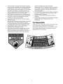
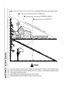
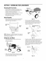
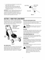
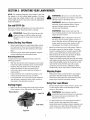
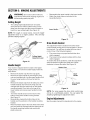
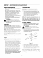
Operator's Manual
21" Self-Propelled
Lawn Mower
Model 378Q
\
IMPORTANT:
Read safety rules and instructions
carefully
Warning:
This unit is equipped with an internal combustion engine and should not be used on or near any unimproved forest-covered,
brush-covered or grass-covered land unless the engine's exhaust system is equipped with a spark arrester meeting applicable local or state
laws (if any). If a spark arrester is used, it should be maintained in effective working order by the operator. In the State of California the
above is required by law (Section 4442 of the California Public Resources Code). Other states may have similar laws. Federal laws apply
on federal lands. A spark arrester for the muffler is available through your nearest authorized engine service dealer or contact the service
department, P.O. Box 361131 Cleveland, Ohio 44136-0019.
MTD PRODUCTSLLC.,P.O.Box361131,Cleveland,Ohio44136-0019
PRINTED IN U.S.A.
FORM NO. 769-01116A
(3/2004)
TABLEOFCONTENTS
Content
Important
SafeOperation
Practices
SlopeGauge
Assembling
YourLawnMower
KnowYourLawnMower
Operating
YourLawnMower
Page
3
6
7
8
Content
Making Adjustments
Maintaining Your Lawn Mower
Troubleshooting
Illustrated Parts List
Page
11
12
14
15
9
Warranty
20
FINDINGMODELNUMBER
This Operator's Manual is an important part of your new lawn mower. It will help you assemble, prepare and
maintain the unit for best performance. Please read and understand what it says.
Before you start assembling your new equipment, please locate the model plate on the
equipment and copy the information from it in the space provided below. A sample model plate is
also given below. You can locate the model plate by standing at the operating position and
looking down at the rear of the deck. This information will be necessary to use the
manufacturer's web site and/or help from the Customer Support Department or an authorized
service dealer.
Copy the model number here:
Copy the serial number here:
_}_,_
k wwwmtdproduots.oom
P. O. BOX 361131
TD
LLC
CLEVELAND,OH
44136
330-220-4683
800-800-7310
CUSTOMER
SUPPORT
Please do NOT return the unit to the retailer from where it was purchased, without first contacting Customer
Support.
If you have difficulty assembling this product or have any questions regarding the controls, operation or
maintenance of this unit, you can seek help from the experts. Choose from the options below:
Visit mtdproducts.com for many useful suggestions. Click on Customer Support button and
you will get the four options reproduced here. Click on the appropriate button and help is
immediately available.
answer
answer you are
iooking for couid be just
a mouse
"
f
aye
looking for cou!d be just
plef_Je.
a mouse
c/IcA away/
It÷e_:i }o_:;_l assisla_:e?
,r
f
circa away!
Clit;_ here te fi_l_
_:_l_tho_z÷ll s÷_vi_÷ ce_ le_s h_ yolll
a_÷a.
To reach the Customer Support Department, please call 1-800-800-7310.
The engine manufacturer is responsible for all engine-related issues with regards to
performance, power-rating, specifications, warranty and service. Please refer to the engine
manufacturer's Owner's/Operator's Manual, packed separately with your unit, for more
information.
SECTION1: IMPORTANT
SAFEOPERATION
PRACTICES
WARNING"
This symbol points out important safety instructions which, if not followed, could endanger
the personal safety and/or property of yourself and others. Read and follow all instructions in this manual
before attempting to operate this machine. Failure to comply with these instructions may result in personal
injury. When you see this symbol--HEED
ITS WARNING.
WARNING"
Engine exhaust, some of its constituents, and certain vehicle components contain or emit
chemicals known to State of California to cause cancer and birth defects or other reproductive harm.
WARNING"
This machine was built to be operated according to the rules for safe operation in this
manual. As with any type of power equipment, carelessness or error on the part of the operator can result in
serious injury. This machine is capable of amputating hands and feet and throwing objects. Failure to
observe the following safety instructions could result in serious injury or death.
GeneralOperation
1.
2.
3.
4.
5.
6.
7.
Read this operator's manual carefully in its entirety
before attempting to assemble this machine. Read,
understand, and follow all instructions on the machine
and in the manual(s) before operation. Be completely
familiar with the controls and the proper use of this
machine before operating it. Keep this manual in a safe
place for future and regular reference and for ordering
replacement parts.
This machine is a precision piece of power equipment,
not a plaything. Therefore, exercise extreme caution at all
times. Your unit has been designed to perform one job: to
mow grass. Do not use it for any other purpose.
Never allow children under 14 years old to operate this
machine. Children 14 years old and over should read and
understand the operation instructions and safety rules in
this manual and should be trained and supervised by a
parent. Only responsible individuals who are familiar with
these rules of safe operation should be allowed to use
this machine.
Thoroughly inspect the area where the equipment is to
be used. Remove all stones, sticks, wire, bones, toys and
other foreign objects which could be tripped over or
picked up and thrown by the blade. Thrown objects can
cause serious personal injury. Plan your mowing pattern
to avoid discharge of material toward roads, sidewalks,
bystanders and the like. Also, avoid discharging material
against a walt or obstruction which may cause
discharged material to ricochet back toward the operator.
To help avoid blade contact or a thrown object injury, stay
in the operator zone behind the handles and keep
children, bystanders, helpers and pets at least 75 feet
from the mower while it is in operation. Stop machine if
anyone enters the area.
Always wear safety glasses or safety goggles during
operation and while performing an adjustment or repair to
protect your eyes. Thrown objects which ricochet can
cause serious injury to the eyes.
Wear sturdy, rough-soled work shoes and close-fitting
slacks and shirts. Shirts and pants that cover the arms
and legs and steel-toed shoes are recommended. Never
operate this machine in bare feet, sandals, slippery or
light weight (e.g. canvas) shoes.
8.
9.
10.
11.
5.
6.
7.
8.
9.
10.
11.
12.
Do not put hands or feet near rotating parts or under the
cutting deck. Contact with the blade can amputate hands
and feet.
A missing or damaged discharge cover can cause blade
contact or thrown object injuries.
Many injuries occur as a result of the mower being pulled
over the foot during a fall caused by slipping or tripping.
Do not hold on to the mower if you are falling; release the
handle immediately.
Never pull the mower back toward you while you are
walking. If you must back the mower away from a wall or
obstruction first took down and behind to avoid tripping
and then follow these steps:
a. Step back from the mower to fully extend your
arms.
b. Be sure you are welt balanced with sure footing.
c. Pull the mower back slowly, no more than halfway
toward you.
d. Repeat these steps as needed.
Do not operate the mower while under the influence of
alcohol or drugs.
Do not engage the self-propelled mechanism on units so
equipped while starting engine.
The blade control handle is a safety device. Never
attempt to bypass its operation. Doing so makes the
safety device inoperative and may result in personal
injury through contact with the rotating blade. The blade
control handle must operate easily in both directions and
automatically return to the disengaged position when
released.
Never operate the mower in wet grass. Always be sure of
your footing. A slip and fall can cause serious personal
injury. If you feel you are losing your footing, release the
blade control handle immediately and the blade will stop
rotating within three seconds.
Mow only in daylight or in good artificial light. Walk, never
run.
Stop the blade when crossing gravel drives, walks or
roads.
If the equipment should start to vibrate abnormally, stop
the engine and check immediately for the cause.
Vibration is generally a warning of trouble.
Shut the engine off and wait until the blade comes to a
complete stop before removing the grass catcher or
unclogging
thechute.
Thecutting
bladecontinues
to
Keep children away from hot or running engines. They
can suffer burns from a hot muffler.
rotate
forafewseconds
aftertheengine
isshutoff.
6.
Never
placeanypartofthebodyinthebladeareauntil
Never allow children under 14 years old to operate a
youaresurethebladehasstopped
rotating.
power mower. Children 14 years old and over should
13. Never
operate
mower
without
proper
trailshield,
read and understand the operation instructions and
discharge
cover,
grasscatcher,
bladecontrol
handle
or
safety rules in this manual and should be trained and
othersafety
protective
devices
inplaceandworking.
supervised by a parent.
Never
operate
mower
withdamaged
safety
devices.
Failure
todoso,canresultinpersonal
injury.
Service
14. Muffler
andengine
become
hotandcancause
aburn.Do
nottouch.
SafeHandlingOfGasoline:
15. Onlyusepartsandaccessories
made
forthismachine
by 1. To avoid personal injury or property damage use extreme
themanufacturer.
Failure
todoso,canresultinpersonal
care in handling gasoline. Gasoline is extremely
injury.
flammable and the vapors are explosive. Serious
16. Ifsituations
occurwhich
arenotcovered
inthismanual,
personal injury can occur when gasoline is spilled on
usecareandgoodjudgment.
Contact
yourdealer
for
yourself or your clothes which can ignite.
assistance.
Telephone
1-800-800-7310
forthename
of
2. Wash your skin and change clothes immediately.
yournearest
dealer.
3. Use only an approved gasoline container.
5,
4.
SlopeOperation
Slopes are a major factor related to slip and fall accidents
which can result in severe injury. Operation on slopes
requires extra caution. If you feel uneasy on a slope, do not
mow it. For your safety, use the slope gauge included as part
of this manual to measure slopes before operating this unit on
a sloped or hilly area. If the slope is greater than 15 degrees,
do not mow it.
5.
6.
Do:
1.
2.
3.
Mow across face of slopes; never up and down. Exercise
extreme caution when changing direction on slopes.
Watch for holes, ruts, rocks, hidden objects, or bumps
which can cause you to slip or trip. Tall grass can hide
obstacles.
Always be sure of your footing. A slip and fall can cause
serious personal injury. If you feel you are losing your
balance, release the blade control handle immediately,
and the blade will stop rotating within 3 seconds.
7.
8.
9.
10.
DoNot:
1.
2.
3.
Do not mow near drop-offs, ditches or embankments,
you could lose your footing or balance.
Do not mow slopes greater than 15 degrees as shown on
the slope gauge.
Do not mow on wet grass.
11.
12.
13.
Children
Tragic accidents can occur if the operator is not alert to the
presence of children. Children are often attracted to the
mower and the mowing activity. They do not understand the
dangers. Never assume that children will remain where you
last saw them.
14.
1.
1.
2.
3.
4.
Keep children out of the mowing area and under the
watchful care of a responsible adult other than the
operator.
Be alert and turn mower off if a child enters the area.
Before and while moving backwards, look behind and
down for small children.
Use extreme care when approaching blind corners, or
other objects that may obscure your vision of a child who
may run into the mower.
15.
Never fill containers inside a vehicle or on a truck or
trailer bed with a plastic liner. Always place containers on
the ground away from your vehicle before filling.
When practical, remove gas-powered equipment from
the truck or trailer and refuel it on the ground. If this is not
possible, then refuel such equipment on a trailer with a
portable container, rather than from a gasoline dispenser
nozzle.
Keep the nozzle in contact with the rim of the fuel tank or
container opening at all times until fueling is complete. Do
not use a nozzle lock-open device.
Extinguish all cigarettes, cigars, pipes and other sources
of ignition.
Never fuel machine indoors because flammable vapors
wilt accumulate in the area.
Never remove gas cap or add fuel while the engine is hot
or running. Allow engine to cool at least two minutes
before refueling.
Never over tilt fuel tank. Fill tank to no more than ½ inch
below bottom of filler neck to provide space for fuel
expansion.
Replace gasoline cap and tighten securely.
If gasoline is spilled, wipe it offthe engine and
equipment. Move unit to another area. Wait 5 minutes
before starting the engine.
Never store the machine or fuel container inside where
there is an open flame, spark or pilot light as on a water
heater, space heater, furnace, clothes dryer or other gas
appliances.
To reduce fire hazard, keep mower free of grass, leaves,
or other debris build-up. Clean up oil or fuel spillage and
remove any fuel soaked debris.
Allow a mower to cool at least 5 minutes before storing.
GeneralService:
2.
Never run an engine indoors or in a poorly ventilated
area. Engine exhaust contains carbon monoxide, an
odorless and deadly gas.
Before cleaning, repairing, or inspecting, make certain
the blade and all moving parts have stopped. Disconnect
the spark plug wire and ground against the engine to
prevent unintended starting.
3. Check
thebladeandengine
mounting
boltsatfrequent
intervals
forproper
tightness.
Also,visually
inspect
blade
fordamage
(e.g.,bent,cracked,
worn)Replace
blade
withtheoriginal
equipment
manufacture's
(O.E.M.)
blade
only,listedinthismanual.
"Useofpartswhichdonot
meettheoriginal
equipment
specifications
mayleadto
improper
performance
andcompromise
safety!"
4. Mower
blades
aresharpandcancut.Wrapthebladeor
weargloves,
anduseextracaution
whenservicing
them.
5. Keepallnuts,bolts,andscrews
tighttobesurethe
equipment
isinsafeworking
condition.
6. Never
tamper
withsafety
devices.
Check
theirproper
operation
regularly.
7. Afterstriking
aforeign
object,
stoptheengine,
disconnect
thesparkplugwireandground
against
theengine.
Thoroughly
inspect
themower
foranydamage.
Repair
thedamage
before
starting
andoperating
themower.
8. Never
attempt
tomakeawheelorcutting
height
adjustment
whiletheengine
isrunning.
9. Grass
catcher
components,
discharge
cover,andtrail
shield
aresubject
towearanddamage
whichcould
expose
moving
partsorallowobjects
tobethrown.
For
safety
protection,
frequently
checkcomponents
and
replace
immediately
withoriginal
equipment
manufacturer's
(O.E.M.)
partsonly,listedinthismanual.
"Useofpartswhichdonotmeettheoriginal
equipment
specifications
mayleadtoimproper
performance
and
compromise
safety!"
10. Donotchange
theengine
governor
setting
oroverspeed
theengine.
Thegovernor
controls
themaximum
safe
operating
speed
oftheengine.
11. Maintain
orreplace
safety
andinstruction
labels,
as
necessary.
12. Observe
proper
disposal
tawsandregulations.
Improper
disposal
offluidsandmaterials
canharmthe
environment.
YourResponsibility
Restrict the use of this power machine to persons who
read, understand and follow the warnings and
instructions
in this manual and on the machine. Some
of the safety labels, placed on the mower, are also
displayed here for your study.
I
o
E
II 91
SIGHT AND HOLD THIS LEVEL WITH A VERTICAL TREE
t-
191
I
-. ,.
I
A POWER POLE
A CORNER OF A BUILDING
I ill
O
" .. ,_
4)
III!
!11
II1
I ,II
I
OR A FENCE POST
I
4)
~ ~ ~FQLDo^.
O
.._"-
iO
I::l
d)
o
*d
r-
t.O
E
o
rd)
o
15 °
o
,_
o)
cu 05
o
WARNING
Do not mow on inclines with a slope in excess of 15 degrees (a rise of approximately 2-1/2 feet every 10 feet). A riding mower could
overturn and cause serious injury. If operating a walk-behind mower on such a slope, it is extremely difficult to maintain your footing
and you could slip, resulting in serious injury.
Operate RIDING mowers up and down slopes, never across the face of slopes.
Operate WALK-BEHIND mowers across the face of slopes, never up and down slopes.
SECTION3: ASSEMBLING
YOURLAWNMOWER
RemovingUnitFromCarton
•
•
•
•
Remove staples, break glue on top flaps, or cut
tape at carton end and peel along top flap to open.
Remove loose parts if included with unit (i.e.,
operator's manual, grass bag etc.)
Cut along corners, lay carton down flat, and remove
packing material and bottle of oil, if any.
Roll or slide unit out of carton and check carton
Tighten these
wing nuts
\
thoroughly for loose parts.
BeforeAssembly
•
Before setting up your lawn mower, disconnect the
spark plug wire from the spark plug and ground
against the engine. See Figure 1.
Spark Plug_
Wire
Figure 3
Pinch the lower handle against the handle
mounting bracket using pliers. See Figure 4.
Move the hairpin clip from the outer to the inner
hole of the weld pin on the handle mounting
bracket. See Figure 4.
Handle Mountin
Bracket
Handle
hairpin
/
Figure 1
Hair
Clip
clip here /
NOTE: Reference
to right or left side of the mower is
observed
from the operating position. Any exceptions
will be stated accordingly.
SettingUpLawnMower
•
Lift the upper handle and align it with the lower
handle. See Figure 2.
Lift Upper Handle up
Figure 4
Fasten the cables to the lower handle with the two
cable ties found on the lower handle. Be sure to
insert the post on the cable ties into the holes
provided on the lower handle. These holes may be
found on either the inside or outside of the handles.
Pull the cable ties tight and trim off the excess.
See Figure 5.
Upper ...... Handle
Lower
Handle
Figure 2
Tighten the wing nuts, shown in Figure 3, and raise
the handle assembly until it clicks into place. Make
sure not to kink the control cables.
Figure 5
•
•
•
Loosen the wing nut holding the rope guide to the
upper handle. See Figure 6.
Squeeze the blade control handle against the
upper handle and pull starter rope out slowly.
Thread the recoil starter rope into the rope guide
and tighten the wing nut.
Starter Rope
\
Upper Handle
Nut
IMPORTANT: This unit is shipped without gasoline or oil
in the engine. Service engine with gasoline and oil as
instructed in the engine manufacturer's owner's/
operator's manual before you start the mower for the
first time, and also for successive uses. The engine
manual is packed seperately in the carton.
Rope Guide
Figure 6
SECTION4: KNOWYOURLAWNMOWER
Read this operator's manual and safety rules before
operating your lawn mower. Compare the illustrations
in Figure 7 with your lawn mower to familiarize yourself
with the location of various controls and adjustments.
Save this manual for future reference.
--
BladeControlHandle(OperatorBail)
The blade control handle is located on the upper handle
of the mower and must be depressed in order to
operate the unit. Release blade control handle to stop
engine and blade.
Blade Control Handle
(Operator Bail)
Choke Lever
-__
_
ARNING:
blade
controlto mechanism
a safety
device.This
Never
attempt
bypass its is
operations.
Drive Clutch Control
GrassBag
Bag
The grass bag, located at the rear of the mower, is used
to bag the grass clippings for disposal at another site.
Once the bag is full, it has to be removed from the
mower and emptied before any further mowing.
CuttingHeightAdjustmentLever
The cutting height adjustment lever is located above
the left rear wheel. To adjust the cutting height, refer to
the Adjustment Section on page 11.
Starter
Rope
MulchingPlug
The mulching plug is used only for mulching purposes.
Instead of collecting grass clippings in a grass catcher,
this mower has the option of recirculating the clippings
back to the lawn. Refer to Figure 9.
EngineControls
Figure 7
DriveClutchControl
The drive clutch control is located on the upper handle.
Squeeze the drive control to engage the drive system.
Release the clutch control to disengage the drive
system. Release the clutch control to slow down when
approaching an obstacle, making a turn, or stopping.
See the engine manual for the location and function of
the controls on the engine.
,_
WARNING:
chute area on the
Keep
cutting
hands
deck.
and The
feet operation
away from
of any lawn mower can result in foreign objects
being thrown into the eyes, which can result in
severe eye damage. Always wear safety
glasses or eye shields while working on the
lawn mower.
SECTION5: OPERATING
YOURLAWNMOWER
NOTE: For shipping purposes your mower is set with
the wheels in a low cutting height position. For best
results raise the cutting position until it is determined
which height is best for your lawn. See the adjustment
section for details.
WARNING:
operator is standing near the lawn mower while
starting engine or operating mower.
WARNING:
Never run engine indoors or in
enclosed, poorly ventilated areas. Engine
exhaust contains carbon monoxide, an
odorless and deadly gas.
GasandOilFill-Up
Service the engine with gasoline and oil as instructed in
the engine manual. Read instructions carefully.
,_
WARNING:
Keep hands, feet, hair and
loose clothing away from any moving parts on
engine and lawn mower.
WARNING"
fuel
tank indoors
with
engine running Never
or untilfillthe
engine
has been
allowed to cool for at least two minutes after
WARNING:
When starting the unit for the
first time, face the mower against a wall or a
fence. Start the unit and if it shows any signs of
motion while the drive clutch control is still
disengaged, shut engine off immediately.
running.
BeforeStartingYourMower
•
•
Attach spark plug wire to spark plug. Make certain
the metal cap on the end of the spark plug wire is
fastened securely over the metal tip on the spark
plug.
Check for proper drive clutch operation using the
neutral adjustment test described below:
Move the choke lever to the ON position. Refer to
the engine manual for further details. Your lawn
mower is equipped with a constant speed throttle,
which is set at full throttle for best performance.
Stand behind the mower and squeeze the blade
control handle against the upper handle.
Grasp recoil starter handle and pull rope out slowly
until engine reaches the start of compression cycle
(rope will pull slightly harder at this point). Let the
rope rewind slowly. Pull the rope with a rapid,
continuous, full arm stroke. Holding the starter
handle firmly, let the rope return to starter slowly.
NeutralAdjustmentTest
To perform the neutral adjustment test answer the
following questions:
•
•
•
•
•
With the drive clutch control released, push mower
forward and pull it backward. Does it move freely?
Squeeze the drive clutch control and pull the
mower backward. Do the rear wheels lock?
Is the drive clutch control cable free of kinks or
sharp bends?
If you answered "yes" to all three questions, your
mower passed the test and you can start it.
If you answered "no" to any of the three questions,
you will have to adjust the drive clutch control as
instructed in the adjustment section.
StoppingEngine
•
•
•
Be sure that the lawn is clear of stones, sticks, wire,
or other objects which could damage the lawn
mower or the engine.
_
WARNING:
Such
objects
could
be direction
accidently thrown
by the
mower
in any
Make sure the fuel valve lever found on the left side
of the engine is in the ON position. See Figure 8.
Recoil Starter
Release the blade control handle to stop engine
and blade. Wait till the blade stops completely.
Disconnect spark plug wire and move away from
spark plug to prevent accidental starting
UsingYourLawnMower
StartingEngine
•
Be sure no one other than the
=
Gas Fill
and cause serious personal injury to the
operator and others.
Valve
Figure 8
For best results, do not cut wet grass because it
tends to stick to the underside of the mower,
preventing proper discharge of grass clippings, and
could cause you to slip and fall. New grass, thick
grass, or wet grass may require a narrower cut.
Fora healthierlawn,nevercutoffmorethanonethirdofthetotallengthofthegrass.Yourlawn
shouldbecutinthefallaslongasthereis growth.
Thismowerisdesignedtobeoperatedatfull
throttletogiveyouthebestcutanddothemost
effective
jobofmowingor mulching.
,i_
AttachingGrassBag
•
•
Lift the rear discharge door and remove the
mulching plug, if installed.
Lift the rear discharge door and hang the grass bag
on the mower. See Figure 10.
WARNING"
the mower
strikeswire
a foreign
object,
stop the Ifengine.
Remove
from the
spark plug, thoroughly inspect the mower for
any damage, and repair the damage before
restarting and operating the mower.
Mulching
For effective mulching, do not cut wet grass because it
tends to stick to the underside of the deck, preventing
proper mulching of grass clippings. New or thick grass
may require a narrower cut. The ground speed should
be adjusted to the condition of the lawn. If mowing has
been delayed and the grass has been allowed to grow
in excess of 4", mulching is not recommended. Mow
using the grass bag to reduce the grass height to 3 114"
maximum before mulching.
Figure 10
EmptyingGrassBag
AttachingMulchingPlug
•
•
For the correct orientation of the mulch plug when
installing it, see Figure 9 inset.
Lift the rear discharge door and remove the grass
bag, if installed. Insert the mulching plug as shown
below in Figure 9.
•
•
Release the blade control handle to shut off engine.
Lift the rear discharge door and pull the bag away
from the mower.
•
Lift the grass bag up and away from the mower.
See Figure 11. Dump the grass clippings at the
appropriate disposal site.
This side down
This side up
Hold rear discharge
door this way
Figure 11
Insert mulch
plug this way
Figure 9
10
SECTION6: MAKINGADJUSTMENTS
,_
Reassemble the upper handle to the lower handle.
Attach the starter rope as instructed in the
Assembly Section.
adjustments without
engineany
and
WARNING:
Do notfirst
at stopping
any time make
disconnecting spark plug wire.
\
CuttingHeight
•
The cutting height adjustment lever is located
above the left rear wheel. Pull the lever out and
away from the mower and then move it forward or
back for a new cutting height. See Figure 12.
Lower
Notch
NOTE: For rough or uneven lawns, move the height
adjustment lever to a higher position. This will help
prevent scalping of grass.
Figure 13
Lower
DriveClutchControl
The adjustment wheel is located in the drive clutch
control handle housing and is used to tighten or loosen
the drive belt. You will have to adjust the drive clutch
control if any of the following happens:
1.
The mower does not propel itself with the drive
clutch engaged;
2. The mower's drive wheels hesitate with the drive
clutch engaged.
To resolve the above problems, rotate the adjustment
wheel clockwise to tighten the cable and counterclockwise to loosen the cable. See Figure 14.
Cutting Height
Adjustment Lever
Figure 12
HandleHeight
Bottom View
Your mower is shipped with the handle in the higher
height position. To lower the handle height, follow the
steps below:
•
•
•
•
•
•
®
Remove the starter rope from the rope guide.
Remove the upper handle by removing the wing
nuts and carriage bolts. Lay the upper handle out of
the way, being careful not to bend or kink the
cables.
Remove the hairpin clips from the weld pins on the
handle brackets and remove the wing nuts and
carriage bolts from the upper hole on the handle
mounting bracket. Press out on the legs of the
lower handle and remove lower handle from the
mower.
Turn lower handle around so the notch on the
bottom of the lower handle is facing forward.
See Figure 13.
Reassemble, placing the bottom holes in the
handle over the weld pins in the handle mounting
bracket.
Place the hairpin clips in the inner holes in the weld
pins and insert the carriage bolts the upper hole on
the handle mounting bracket and secure with
plastic wing nuts.
pper
Handle
Adjustment
Wheel_
Control
Figure 14
NOTE: For some people the drive clutch control may
not be in a comfortable position. You can adjust the
handle by tightening the adjustment wheel.
EngineAdjustments
See the engine manual for adjustments to the engine.
11
SECTION7: MAINTAININGYOURLAWNMOWER
GeneralRecommendations
Cleaningthe Deck
•
Always observe safety rules when performing any
maintenance.
IMPORTANT:We do not recommend the use of a
•
The warranty on this lawn mower does not cover
items that have been subjected to operator abuse
or negligence. To receive full value from the
warranty, the operator must maintain the lawn
mower as instructed in this manual.
•
Some adjustments will have to be made
periodically to maintain your unit properly. Refer to
the earlier section for details.
•
Periodically check all fasteners and make sure
these are tight.
_
pressure washer or garden hose to clean your unit.
Clean the underside of the mower deck after each
use to prevent a build-up of grass clippings, leaves,
dirt etc. If this debris is allowed to accumulate, it will
invite rust and corrosion, and may affect the
mower's performance. Tilt the equipment and
scrape it clean with a suitable tool.
NOTE: When tipping the unit, empty the fuel tank and
keep the air cleaner side of engine up. Never tip the
mower more than 90 degrees and do not leave the
mower tipped for any length of time. Oil can drain into
the upper part of the engine causing a starting problem.
disconnect spark
WARNING"
Always
plug wire
stop before
engine cleaning,
and
lubricating, or doing any kind of service work on
the lawn mower.
ServicingtheBlade
•
Lubrication
Blade Control Handle: Lubricate the pivot points on
the blade control handle and the drive clutch control at
least once a season with light oil. These handles must
operate freely in both directions.
Wheels: Lubricate the wheels at least once a season
with light oil (or motor oil). If the wheels are removed for
any reason, lubricate the surface of the axle bolt and
inner surface of the wheel with light oil.
Periodically inspect the blade adapter for cracks,
especially if you strike a foreign object. Replace
when necessary.
_
WARNING:
When
handling
the
blade,gloves
protect your hands
with
a pair of
heavy
or use a heavy rag.
•
Remove the bolt and the blade bell support which
hold the blade and the blade adapter to the engine
crankshaft. See Figure 15.
Rear Discharge Door: Lubricate the torsion spring and
pivot point periodically with light oil to prevent any rust
or binding.
Blade
Adapter
Blade Bell
_ort
Engine: Follow the engine manual for instructions.
Engine
Bolt
Refer to the engine manual for all engine maintenance
instructions.
•
•
•
•
Maintain engine oil as instructed in the engine
manual. Fill up with correct grade and amount of oil.
Service air cleaner every 25 hours under normal
conditions. Poor engine performance and flooding
usually indicate that the air cleaner should be
serviced. For details, refer to the engine manual.
The spark plug should be cleaned and the gap
reset once a season. Spark plug replacement is
recommended at the start of each mowing season.
Clean the engine regularly with a cloth or brush.
Keep the cooling system (blower housing area)
clean to permit proper air circulation which is
essential to engine performance and life. Be certain
to remove all grass, dirt, and combustible debris
from muffler area.
Figure 15
Remove blade and adapter from the crankshaft.
When sharpening the blade, follow the original
angle of grind as a guide. It is extremely important
that each cutting edge receives an equal amount of
grinding to prevent an unbalanced blade.
NOTE:
vibration
damage
personal
12
An unbalanced blade will cause excessive
when rotating at high speeds. It may cause
to the mower, and could break, causing
injury.
•
•
•
•
•
•
•
Test the blade by balancing it on a round shaft
screwdriver. Remove metal from the heavy side
until it balances evenly. It is recommended that the
blade always be removed from the adapter when
testing for balance.
Before reinstalling the blade and the blade adapter
to the unit, lubricate the engine crankshaft and the
inner surface of the blade adapter with light oil.
Be sure to install the blade with the side marked
•
•
•
Tip the mower back on its handle and block
securely.
Remove the blade, blade adapter and related
hardware. See Figure 17.
Remove the three hex head screws holding the
small baffle and remove the small baffle. Remove
the large baffle as well. See Figure 17.
Baffl_
"bottom" (or with part number) facing the ground
when the mower is in the operating position.
Slide the blade adapter onto the engine crankshaft.
Place the blade on the adapter. Align the blade so
that it is seated on the blade adapter flanges.
Place blade bell support on blade. Make sure the
notches on the blade bell support are aligned with
small holes in the blade.
Blade Adapter
_e
Baffle
Hex
Screw
Replace hex bolt and tighten to torque: 450 in. Ibs.
min., 600 in. Ibs. max.
NOTE: To ensure safe operation of your mower, the
blade bolt must be checked periodically for correct
torque.
Figure 17
DriveBeltReplacement
Loosen the hex lock nut holding the idler bearing.
Push back and rotate the belt keeper as shown in
Figure 18.
Belt Keeper
/
\
If you need to replace a worn or broken drive belt, follow
steps below:
•
•
•
Disconnect the spark plug wire and ground it
against the engine.
Drain the fuel tank or place a piece of plastic
beneath the cap to prevent gasoline leakage.
Remove the rear hub caps, rear wheels and eight
screws shown in Figure 16.
Hex Lock Nut
"/
/-_-_
\
/
Figure 18
NOTE: Mower is shown tipped on engine in this figure
for clarity. Remember, only tip mower back on its
handle with the spark plug facing up. Otherwise, oil will
spill if turned upside down.
•
•
7
•
•
•
•
•
Figure 16
13
Remove and replace the belt.
Replace the belt keeper to its original position and
tighten the hex lock nut.
Replace the large baffle. Refer to Figure 17.
Replace small baffle and three hex head screws
holding it in place.
Replace the blade adapter and blade. See earlier
instructions for proper assembly.
Replace the eight phillips head screws that hold the
large baffle in place. Refer to Figure 16.
Replace the rear wheels, rear wheel gears, and
hub caps. The gear needs to be put on in the right
wayfortheselfpropelledmechanism
towork.
Checktheinstallation
ofthegearbyspinningthe
wheel.It shouldspinfreelyinonedirectionbutnot
theother.If thewheelspinsfreelyinboth
directions,
flipthegearover.
Tipthemowerbackontoitswheelsandperformthe
neutraladjustment
testdescribed
onpage9.
•
•
•
Clean and lubricate mower thoroughly as described
in the lubrication instructions.
Follow the engine manual for engine storage.
Coat mower's cutting blade with chassis grease to
prevent rusting.
NOTE: When storing any type of power equipment in a
poorly ventilated or metal storage shed, care should be
taken to rust-proof the equipment. Using a light oil or
silicone, coat the equipment, especially cables and all
moving parts.
StoringyourLawnMower
If the lawn mower is not going to be used for 30 days or
more, prepare your lawn mower for storage.
•
Store mower in a dry, clean area, but not near
corrosive materials such as fertilizer.
SECTION8: TROUBLE
SHOOTING
GUIDE
Problem
Cause
Engine fails to start
1.
2.
3.
4.
Remedy
5.
Blade control handle disengaged.
1.
Spark plug wire disconnected.
2.
Fuel tank empty or stale fuel.
3.
Fuel line blocked orfuel valve in the OFF 4.
position.
Choke not activated.
5.
6.
7.
1.
2.
Faulty spark plug.
Engine flooded.
Spark plug wire loose.
Blocked fuel line or stale fuel.
6.
7.
1.
2.
3.
4.
5.
6.
1.
2.
3.
1.
Vent in gas plugged.
Water or dirt in fuel system.
Dirty air cleaner.
Carburetor out of adjustment.
Engine oil level tow.
Air flow restricted.
Carburetor not adjusted properly.
Spark plug gap too close.
3.
4.
5.
6.
1.
2.
3.
1.
Excessive vibration
1.
2.
3.
1.
Mower will not mulch grass
2.
1.
Spark plug fouled, faulty or gap too wide. 1.
Carburetor improperly adjusted.
2.
Dirty air cleaner.
3.
Cutting blade loose or unbalanced.
1.
2.
Bent cutting blade.
1,
Wet grass.
2.
Excessively high grass.
2.
Uneven cut
3.
1.
Dull blade.
Wheels not positioned correctly.
3.
1.
2.
Wheels will not propel
2.
1.
Dull blade.
Belt not installed properly.
1.
2.
Debris clogging drive operation.
2.
Engine runs erratic
Engine overheats
Occasional skip (hesitates) at
high speed
Idles poorly
NOTE:
For repairs
beyond
the minor adjustments
fisted above,
14
contact
Engage blade control handle.
Connect wire to spark plug.
Fill tank with clean, fresh gasoline.
Clean fuel line or place fuel valve in the ON
position.
Move choke lever backward into the CHOKE
position.
Clean, adjust gap, or replace.
Wait a few minutes to start engine.
Connect and tighten spark plug wire.
Clean fuel line; fill tank with clean, fresh
gasoline.
Clear vent.
Drain fuel tank. Refill with fresh fuel.
Clean air cleaner.
Adjust carburetor.
Fill crankcase with proper oil.
Remove blower housing and clean.
Adjust carburetor.
Adjust gap to.030".
Reset gap to.030" or replace spark plug.
Adjust carburetor.
Clean air cleaner.
Tighten blade and adapter. Balance blade.
Replace blade.
Do not mow when grass is wet; wait until later
to cut.
Mow once at a high cutting height, then mow
again at desired height or make a narrower
cutting path.
Sharpen or replace blade.
Place all four wheels in same height position.
Sharpen or replace blade.
Check belt for proper pulley installation and
movement.
Clean out debris with engine off.
your local authorized
service
dealer.
SECTION9: PARTSLISTFORMODEL378
37
36
\\\
16
38
R\\\\\\\\\
_*
36
22
44
8
0
R\\\\
39
42
34\
32
26 7
33
3Q
18
40
13
Ref. No.
1.
2.
3.
4.
5.
6.
7.
8.
9.
10.
11.
12.
13.
14.
15.
16.
17.
18.
19.
20.
21.
22.
23.
Part No.
638-0005
682-7518
682-7524
748-0381
748-0188B
710-0653
710-0751
710-1315
710-1652
711-0835
713-0421
714-0474
720-0230
738-0137A
732-0803A
732-0818
736-0270
736-0369
10622B
738-0529
741-0324A
741-0522
741-0978
748-0318
Description
Rear Axle Assembly
Trans axle Assembly
Chain Cover Assembly
Pawt RH
Pawt LH
TT Screw 1/4-20 x 0.375"
Hex Bolt 1/4-20 x 0.620"
TT Screw 3/8-16 x 1.25"
TT Screw 1/4-20 x 0.625"
Clevis Pin
Chain
Cotter Pin
Foam Grip
Shoulder Screw
Height Adjustment Lever
Torsion Spring RH
Belt Washer
Flat Washer
Ref. No.
24.
25.
26.
27.
28.
29.
30.
31.
32.
33.
34.
35.
36.
37.
38.
39.
40.
Ratchet Spring
Shoulder Nut
41.
42.
Hex Flange Bearing
Hex Flange Bearing
Hex Slev Bearing
Ratchet Wheel
43.
44.
45.
46.
15
Pa_ No.
750-0807
750-1056
750-1075
782-0566B
782-0568
16855
712-0414
634-0020
738-0102
731-0981A
710-1348
732-04074
750-1068
782-7599B
747-0922
782-3030
782-3029
611-0060
736-0105
714-0104
732-0820
747-0920A
710-0604A
618-0263A
Description
Spacer
Shoulder Spacer
Slev Spacer
Pivot Arm
Lift Assist Bracket
Pawl Plate: Ratchet
Top Lock Weld Nut
Wheel
Shoulder Screw
Hubcap
AB Screw 1/4-14 x 0.5"
Torsion Spring LH
Shoulder Spacer
Grass Bag Door
Pivot Rod
Handle Bracket RH
Handle Bracket LH
Front Axle
Belt Washer
Cotter Pin
Extension Spring
Adjustment Rod
Screw
Transmission (Breakdown on page 18
Model378
2
\
1
,/
14
18
\\
19
\
31\
32
35 36
52
39
16
Model378Q
Ref.
No.
Pa_No.
Description
1.
710-1667
Hi-Lo Screw
2.
731-1058
3.
731-0620
Control Housing: Lower
Drive Control Lever
4.
731-1057
Control Housing: Upper
5.
731-1059
Mounting Cap: SP Cable
6.
710-1205
7.
720-0279
Eye Bolt
Handle Knob
8.
749-0439B
Upper Handle
Hex Lock Nut 1/4-20
9.
712-0324
10.
746-0875
11.
710-0605
12.
736-0501
13.
746-0876
14.
710-1174
15.
736-0451
16.
720-0284
17.
749-0907B
Knob Assembly
Lower Handle
18.
664-0080
Grasscatcher Assembly
19.
712-0397
Wing Nut
20.
714-0104
21.
710-0703
Hairpin Clip
Hex Bolt
22.
710-1652
TT Screw 1/4-20 x 0.625"
23.
782-7018
24.
732-0700
Pulley Cover
Traitshield Wire
25.
731-1236A
Traitshield
26.
710-1220
Hi-Lo Screw #12-14 x 0.750"
Throttle Housing
Machine Screw 1/4-20 x 1.825"
Spring Washer
Throttle Lever
Carriage Bolt 5/16-18 x 2.0"
Saddle Washer
Ref.
No,
Pa_ No.
Description
27
28
29
30
31
32
731-1714A
Belt Cover
736-3020
Flat Washer
736-0329
Lock Washer
712-0287
Hex Nut 1/4-20
710-0351
B Screw #10-16 x 0.5"
712-0400
U Nut
33
34
35
36
37
38
710-0653
TT Screw 1/4-20 x 0.375"
710-1026
TT Screw 1/4-20 x 1.75"
726-0240
Cable Tie
39
40
41
42
43
44
45
46
47
48
49
50
51
52
17
731-1639
Rear Baffle
746-0713A
S.R Cable
742-0741
710-1257
Mulching Blade
Hex Bolt 3/8-24 x 2.5"
736-0524B
Blade Belt Support
748-0377C
736-0514
Blade Adapter
Flat Washer
736-0513
Spring Washer
748-0358
Engine Spacer
756-0979
Pulley Half
756-0962
746-04131
Pulley Half: Upper
Choke Cable
746-0557
Control Cable
782-0075A
Cutting Deck Assembly
Blade Control Bait
757-0824
782-5014
754-0271
Front Baffle (not shown)
Belt 3/8 x 39"
Model378
_._
2
2
4
12
13
15
\\\
29
14
_27
\\
J
_30
25
28
_\\\\
23
_33
\\\
16
\\\\
17
22
20
21
18
Model378
Ref.
Part No.
Description
712-3025
Hex Jam Nut 5/16-24
736-0425
Bell Washer
756-0656
736-3084
Pulley
Flat washer
712-0896
Hex Jam Nut
782-7598
Belt Keeper
741-0124
Bearing
7501050
Flange Spacer
682-0027A
Idler Bracket Assembly
710-0299
Hex Cap Screw
Torsion Spring
No.
1.
2.
3.
4.
5.
6.
7.
8.
9.
10.
11.
12.
13.
14.
15.
16.
17.
18.
19.
20.
21.
22.
23.
24.
25.
26.
27.
28.
29.
30.
31.
32.
33.
34.
732-0849A
741-0682A
736-0570
Bearing Sleeve
Flat Washer
721-0329
Oil Seal
618-0253
Upper Housing Assembly
Flat Washer717-1487
736-0616
714-1487
Pinion Shaft 10 T.
736-0314
Thr. Washer
736-0569
Thr. Washer
618-0252
710-0642
Lower Housing Assembly
Hex Screw 1/2-20 x 0.75"
782-7601A
Cable Bracket
741-0674
611-0066
Shaft Assembly
741-0678
Bearing
717-1469
Bearing Sleeve
Gear 34 T.
711-1168
Output SHft 6 T.
741-0673
Flange Bearing
Oil Seal
Pivot Bracket
721-0329
782-7595
741-0324A
736-0369
Flange Bearing
Flat Washer
741-0690
Thrust Bearing
618-0263A
Transmission Assembly Complete
19
MANUFACTURER'S
LIMITED WARRANTY
The limited warranty set forth below is given by MTD LLC with
respect to new merchandise purchased and used in the
United States, its possessions and territories.
e,
"MTD"warrants this product against defects in material and
workmanship for a period of two (2) years commencing on the
date of original purchase and wilt, at its option, repair or
replace, free of charge, any part found to be defective in
materials or workmanship. This limited warranty shall only
apply if this product has been operated and maintained in
accordance with the Operator's Manual furnished with the
product, and has not been subject to misuse, abuse,
commercial use, neglect, accident, improper maintenance,
alteration, vandalism, theft, fire, water, or damage because of
other peril or natural disaster. Damage resulting from the
installation or use of any part, accessory or attachment not
approved by MTD for use with the product(s) covered by this
manual will void your warranty as to any resulting damage.
f,
g.
The provisions as set forth in this warranty provide the
sole and exclusive remedy arising from the sale. MTD
shall not be liable for incidental or consequential loss or
damage including, without limitation, expenses incurred
for substitute or replacement lawn care services or for
rental expenses to temporarily replace a warranted
product.
HOW TO OBTAIN SERVICE: Warranty service is available,
WITH PROOF OF PURCHASE, through your local authorized
service dealer. To locate the dealer in your area, check your
Yellow Pages, or contact MTD LLC at P.O. Box 361131,
Cleveland, Ohio 44136-0019, or call 1-800-800-7310 or 1330-220-4683 or tog on to our Web site at
www.mtdproducts.com.
Some states do not allow the exclusion or limitation of
incidental or consequential damages, or limitations on how
long an implied warranty lasts, so the above exclusions or
limitations may not apply to you.
In no event shall recovery of any kind be greater than the
amount of the purchase price of the product sold. Alteration
of safety features of the product shall void this warranty.
You assume the risk and liability for toss, damage, or injury to
you and your property and/or to others and their property
arising out of the misuse or inability to use the product.
This limited warranty does not provide coverage in the
following cases:
b,
C.
d,
MTD does not extend any warranty for products sold or
exported outside of the United States, its possessions
and territories, except those sold through MTD's
authorized channels of export distribution.
Replacement parts that are not genuine MTD parts.
Transportation charges and service calls.
No implied warranty, including any implied warranty of
merchantability of fitness for a particular purpose,
applies after the applicable period of express written
warranty above as to the parts as identified. No other
express warranty, whether written or oral, except as
mentioned above, given by any person or entity,
including a dealer or retailer, with respect to any product,
shall bind MTD. During the period of the warranty, the
exclusive remedy is repair or replacement of the product
as set forth above.
Normal wear parts are warranted to be free from defects in
material and workmanship for a period of thirty (30) days from
the date of purchase. Normal wear parts include, but are not
limited to items such as: batteries, belts, blades, blade
adapters, grass bags, rider deck wheels, seats, snow thrower
skid shoes, shave plates, auger spiral rubber and tires.
a,
FOR:
The engine or component parts thereof. These items
may carry a separate manufacturer's warranty. Refer
to applicable manufacturer's warranty for terms and
conditions.
Log splitter pumps, valves, and cylinders have a
separate one year warranty.
Routine maintenance items such as lubricants, filters,
blade sharpening, tune-ups, brake adjustments, clutch
adjustments, deck adjustments, and normal
deterioration of the exterior finish due to use or
This limited warranty shall not extend to anyone other than the
original purchaser or to the person for whom it was purchased
as a gift.
HOW STATE LAW RELATES TO THIS WARRANTY: This
limited warranty gives you specific legal rights, and you may
also have other rights which vary from state to state.
IMPORTANT: Owner must present Original Proof of
Purchase to obtain warranty coverage.
exposure.
Service completed by someone other than an
authorized service dealer.
MTD LLC, P.O.BOX361131CLEVELAND,OHIO44136-0019; Phone:1-800-800-7310,1-330-220-4683
2O