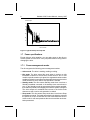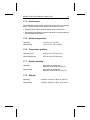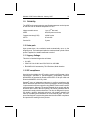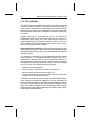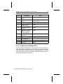
1
.................................... Medalist 2132 (ST32132A) .................................... ATA Interface Drive .................................... .................................... .................................... Product Manual .................................... .................................... Medalist 2132 (ST32132A) .................................... ATA Interface Drive .................................... .................................... .................................... Product Manual .................................... © 1997 Seagate Technology, Inc. All rights reserved Publication Number: 39306-001, Rev. A, January 1997 Seagate, Seagate Technology, the Seagate logo, Medalist and the Medalist logo are registered trademarks of Seagate Technology, Inc. Other product names are trademarks or registered trademarks of their owners. Seagate reserves the right to change, without notice, product offerings or specifications. No part of this publication may be reproduced in any form without written permission from Seagate Technology, Inc. Medalist 2132 Product Manual, January 1997 iii Contents Introduction . . . . . . . . . . . . . . . . . . . . . . . . . . . . . 1 Specifications summary table . . . . . . . . . . . . . . . . . . . 2 1.0 Drive Specifications . . . . . . . . . . . . . . . . . . . . . . . 5 1.1 Formatted Capacity . . . . . . . . . . . . . . . . . . . . . . 5 1.2 Physical organization . . . . . . . . . . . . . . . . . . . . . 6 1.3 Functional specifications . . . . . . . . . . . . . . . . . . . 6 1.4 Physical dimensions . . . . . . . . . . . . . . . . . . . . . . 6 1.5 Seek time . . . . . . . . . . . . . . . . . . . . . . . . . . . 7 1.6 Start and stop time . . . . . . . . . . . . . . . . . . . . . . 7 1.7 Power specifications . . . . . . . . . . . . . . . . . . . . . . 8 1.7.1 Power-management modes . . . . . . . . . . . . . . . 8 1.7.2 Voltage tolerances . . . . . . . . . . . . . . . . . . . 10 1.7.3 Conducted noise . . . . . . . . . . . . . . . . . . . . 10 1.7.4 Environment . . . . . . . . . . . . . . . . . . . . . . 11 1.7.5 Ambient temperature . . . . . . . . . . . . . . . . . . 11 1.7.6 Temperature gradient . . . . . . . . . . . . . . . . . . 11 1.7.7 Relative humidity . . . . . . . . . . . . . . . . . . . . 11 1.7.8 Altitude . . . . . . . . . . . . . . . . . . . . . . . . . 11 1.7.9 Shock and vibration . . . . . . . . . . . . . . . . . . 12 1.8 Acoustics . . . . . . . . . . . . . . . . . . . . . . . . . . 12 1.9 Reliability . . . . . . . . . . . . . . . . . . . . . . . . . . 13 1.10 Auto-park . . . . . . . . . . . . . . . . . . . . . . . . . . 13 1.11 Agency listings . . . . . . . . . . . . . . . . . . . . . . . 13 1.12 EC compliance . . . . . . . . . . . . . . . . . . . . . . . 13 1.13 FCC verification . . . . . . . . . . . . . . . . . . . . . . 14 2.0 Configuring and mounting the drive . . . . . . . . . . . . . 15 2.1 Handling and static-discharge precautions . . . . . . . . . 15 2.2 The ATA interface connector . . . . . . . . . . . . . . . . 17 2.3 Power connector . . . . . . . . . . . . . . . . . . . . . . . 17 2.4 Master/slave jumper block . . . . . . . . . . . . . . . . . . 17 iv Medalist 2132 Product Manual, January 1997 2.4.1 Master/slave configuration . . . . . . . . . . . . . . . 18 2.4.2 Cable-select option . . . . . . . . . . . . . . . . . . . 18 2.4.3 Diagnostics Jumper . . . . . . . . . . . . . . . . . . 19 2.5 Mounting the drive . . . . . . . . . . . . . . . . . . . . . . 20 3.0 ATA interface . . . . . . . . . . . . . . . . . . . . . . . . . 23 3.1 ATA interface connector pin assignments . . . . . . . . . . 23 3.2 Bus signal levels . . . . . . . . . . . . . . . . . . . . . . . 23 3.3 Supported ATA commands . . . . . . . . . . . . . . . . . 25 3.3.1 Identify Drive command (ECH) . . . . . . . . . . . . . 27 3.3.2 Format track command (50H) . . . . . . . . . . . . . . 29 3.3.3 Set Features command (EFH) . . . . . . . . . . . . . 30 3.3.4 Set Multiple Mode command (C6H) . . . . . . . . . . 32 3.3.5 Read Multiple command (C4H) . . . . . . . . . . . . . 32 3.3.6 Write Multiple command (C5H) . . . . . . . . . . . . . 33 3.4 S.M.A.R.T. command (B0H) . . . . . . . . . . . . . . . . . 34 3.5 Drive Security Commands . . . . . . . . . . . . . . . . . . 35 3.6 Onboard drive diagnostics . . . . . . . . . . . . . . . . . . 35 3.7 ECC performance tests . . . . . . . . . . . . . . . . . . . 36 3.8 Supported BIOS . . . . . . . . . . . . . . . . . . . . . . . 36 Medalist 2132 Product Manual, January 1997 v Figures Figure 1. Typical startup current profile . . . . . . . . . . . . . . . . 8 Figure 2. Connectors . . . . . . . . . . . . . . . . . . . . . . . . 16 Figure 3. ATA interface connector . . . . . . . . . . . . . . . . . 17 Figure 4. Master/slave jumper block settings . . . . . . . . . . . . 18 Figure 5. Connecting cable-selected drives . . . . . . . . . . . . . 19 Figure 6. Standard mounting dimensions . . . . . . . . . . . . . . 21 Figure 7. ATA interface connector pin assignments . . . . . . . . 24 vi Medalist 2132 Product Manual, January 1997 Medalist 2132 Product Manual, January 1997 1 Introduction This manual describes the functional, mechanical and interface specifications for the Medalist® 2132 hard disc drive. The drive is referred to throughout this manual by its model number, ST32132A. The ST32132A drive is designed to meet the needs of entry-level to midrange desktop computers. It is a standard 3.5-inch form-factor drive that features PRML recording technology, advanced transfer modes, multiple block read/write, segmented cache, power management and S.M.A.R.T. capabilities. The drive’s 2.1-Gbyte capacity provides ample space to store large software programs and allows these programs to run efficiently. Fast ATA-3 performance is available on this drive. The Medalist 2132 supports advanced PIO modes 3 and 4 and advanced multiword DMA modes 1 and 2 for burst transfer rates up to 16.6 Mbytes per second. The drive supports multiple block read/write, which allows it to store contiguous blocks of data in its 128-Kbyte segmented cache and to transfer the blocks in a single burst. The drive supports power-management modes for energy-efficient operation. Power dissipation falls to 0.84W (typical) in Standby mode. The drive enters power-saving modes at the request of the host. It can also be programmed to automatically enter power-saving modes using the Idle timer or Standby timer commands. The power-management modes the drive supports are discussed in Section 1.7.1 on page 8. The power-management commands the drive supports are listed in the ATA-command table on page 25. 2 Medalist 2132 Product Manual, January 1997 Specifications summary table The following table serves as a quick reference for the ST32132A performance specifications. These and other specifications are discussed in the Drive Specifications section following the table. Drive specification ST32132A 1 6 Guaranteed capacity (Mbytes ) (×10 bytes) 2,113.413 Guaranteed sectors 4,127,760 Bytes per sector 512 Sectors per track 63 Logical Read/Write heads 16 Logical cylinders 4,095 Physical Read/Write heads 6 Physical discs 3 Recording density (kbits) 89 Track density (tracks per inch) 5,435 Spindle speed (RPM) 4,504 Track-to-track seek time (msec typical) 2.5 Average seek time (msec typical) 12.5 Full-stroke seek time (msec typical) 30 Average latency (msec) 6.66 Internal data-transfer rate (Mbits per sec max) 35 to 68.0 External transfer rate (Mbytes per sec max) PIO mode 16.6 External transfer rate (Mbytes per sec max) DMA mode 16.6 Cache buffer (Kbytes) 128 Height (inches max) 1.00 Width (inches max) 4.02 Depth (inches max) 5.77 Typical weight (lb) 1.3 Power-on to ready (sec typical) 7 Spinup current (typical) 1.31A __________________________ 1. One Mbyte equals one million bytes. Medalist 2132 Product Manual, January 1997 3 Drive specification ST32132A Seek power (typical) 5.98W Read/Write power (typical) 4.97W Idle total power (typical) 3.24W Standby power (typical) 0.84W Voltage tolerance (including noise): +5V ± 5% Voltage tolerance (including noise): +12V ± 5% Operating temperature (°C) 5° to 55°C Nonoperating temperature (°C) –40° to 70°C Operating temperature gradient (°C per hour max) 20°C Relative humidity, operating gradient (max) 10% per hour Altitude, operating –1,000 to 10,000 ft. Altitude, nonoperating –1,000 to 40,000 ft. Shock, normal operating (Gs max at 11 msec) 2.0 Gs Shock, nonoperating (Gs max at 11 msec) 125 Gs Vibration (Gs max at 22–300 Hz without nonrecoverable 1.0 G errors), operating Peak to Peak Vibration (Gs max at 22–300 Hz with no physical 8.0 Gs damage incurred), nonoperating Peak to Peak Drive acoustics, Idle mode (dBA), typ 30 dBA Nonrecoverable read errors (per bits transferred) 1013 Mean time between failures (power-on hours) 300,000 Contact start-stop cycles 40,000 Service life (years) 5 4 Medalist 2132 Product Manual, January 1997 Medalist 2132 Product Manual, January 1997 5 1.0 Drive Specifications 1.1 Formatted Capacity The drive is low-level formatted at the factory. You do not need to low-level format the drive. This drive supports cylinder-head-sector (CHS) and logical-block addressing (LBA) translation modes. You can use the Identify drive (ECH) command to verify the address modes the drive supports, the number of cylinders, sectors per track, total number of sectors, heads and other parameters. The Identify drive parameters are listed in Section 3.3.1. on page 26. CHS LBA Cylinders 4,095 Heads 16 Sectors per track 63 Guaranteed capacity (bytes) 2,113,413,120 2,113,413,120 Guaranteed sectors 4,127,760 4,127,760 6 Medalist 2132 Product Manual, January 1997 1.2 Physical organization Heads 6 Discs 3 1.3 Functional specifications Interface ATA-3 Internal data-transfer rate (Mbits/sec) 35.0 to 68.0 External data-transfer rate (Mbytes/sec) PIO Mode 4 16.6 (max) DMA Mode 2 16.6 (max) Spindle speed ± 0.5% (RPM) 4,504 Segmented cache (Kbytes) 128 Zone Bit Recording method PRML (0,12,8) Bytes per sector 512 Recording density, max (BPI) 89K Flux density, max (FCI) 97K Track density, max (TPI) 5,435 1.4 Physical dimensions Height (max) 1.00 inch (25.4 mm) Width (max) 4.02 inches (102.1 mm) Depth (max) 5.77 inches (146.6 mm) Weight (max) 1.3 lb (0.59 Kg) Medalist 2132 Product Manual, January 1997 7 1.5 Seek time Seek value is the interval between the time the actuator begins to move and the time the head has settled over the target track. Seek time is a true statistical average of at least 10,000 measurements of seek time. All measurements are taken under nominal conditions of temperature and voltage with the drive mounted horizontally. The specifications in the table below are defined as follows: • Track-to-track seek time is an average of all possible single-track seeks in both directions. • Average seek time is a true statistical random average of at least 10,000 measurements of seeks between random tracks, less overhead. • Full-stroke seek time is one-half the time needed to seek from the first data cylinder to the maximum data cylinder and back to the first data cylinder. The full-stroke average is determined by measuring 100 full-stroke seeks in both directions. Track-to-track typ (msec) 2.5 Average typ (msec) 12.5 Full-stroke typ (msec) Latency (msec) 30 6.66 1.6 Start and stop time The drive is ready within 10 seconds. Typical and maximum start and stop times are shown in the following table. Figure 1 on page 8 shows a typical startup current profile. Typical Maximum Start time 7 sec 11 sec Stop time 6 sec 9 sec 8 Medalist 2132 Product Manual, January 1997 Current in amps 1.2 1.0 0.8 0.6 0.4 0.2 0 2 4 6 8 10 12 14 16 Time in seconds Figure 1. Typical startup current profile 1.7 Power specifications Except during a write operation, you can apply power to the drive or remove power from the drive in any sequence without losing data or damaging the drive. 1.7.1 Power-management modes The drive supports the following power-management modes: • Active mode. The drive is seeking, reading or writing. • Idle mode. The drive enters Idle mode when it receives an Idle Immediate command or the idle timer counts down to zero. In Idle mode the spindle remains up to speed, the segmented cache remains enabled, and the drive accepts all commands and returns to the Active mode whenever a seek, read or write operation is needed. • Standby mode. The drive enters Standby mode when it receives a Standby Immediate command or the standby timer counts down to zero. In the Standby mode the segmented cache remains enabled, the heads are parked in the shipping zone and the spindle is stopped. The drive accepts all commands and returns to the Active mode whenever a seek, read or write operation is needed. • Sleep mode. The drive enters Sleep mode when it receives a Sleep Immediate command. The heads are parked in the shipping zone and the spindle is at rest. A hard reset or a soft reset returns the drive to Active mode. A soft reset preserves the current emulation and translation parameters. Medalist 2132 Product Manual, January 1997 1.7.1.1 9 Idle and Standby timers The drive can enter the Idle mode or the Standby mode by two different methods: • The computer sends an Idle Immediate command or a Standby Immediate command. • The idle timer or the standby timer counts down to zero. The Idle and Standby timers are disabled at the factory. Use the computer’s setup utility to enable and to set the timer delays. When the Idle timer is enabled, it is initialized each time the drive completes a read, write or seek. If the Idle timer reaches zero before any drive activity is required, the drive goes into the Idle mode, and the Standby timer, if it is enabled, is initialized. If the Standby timer reaches zero before any drive activity is required, the drive goes into the Standby mode. See the Seagate ATA Interface Reference Manual, publication number 36111-xxx, for details. In both the Idle and Standby modes, the drive accepts all commands and returns to the Active mode any time disc access is necessary. There may be a slight delay between the time the drive receives the command and the time drive activity begins. 1.7.1.2 Power consumption The following guidelines are used to measure power consumption: • All measurements are taken at sea level with an ambient temperature of 25°C. • All typical measurements are taken using nominal voltages; the peak startup power is measured using the nominal voltages. • Seek current measurements are taken using an RMS meter while the drive is randomly seeking with two spindle rotations between each seek. 10 Medalist 2132 Product Manual, January 1997 Mode Current (amps) Power (watts) +12V +5V 1.31 0.35 10.23 Read/write (typ) 0.39 0.26 0.26 0.37 5.98 4.97 Idle2 (typ) 0.22 0.12 3.24 2 0.02 0.12 0.84 0.02 0.07 0.59 Spinup (peak) Active Seeking (typ) Standby (typ) 2 Sleep (typ) 1.7.2 Voltage tolerances Voltage tolerance including noise 1.7.3 +5V +12V ± 5% ± 5% ± 10% during spinup Conducted noise The drive is expected to operate with a maximum of: • 150 mV peak-to-peak triangular-wave injected noise at connector. The frequency is 10 Hz to 100 KHz with resistive loads.4 • 100 mV peak-to-peak triangular-wave injected noise at connector. The frequency is 100 KHz to 10 MHz with resistive loads.4 the power equivalent the power equivalent ____________________ 2. These values apply only when power management is enabled. To enable power management, use the computer’s setup utility. 3. Spinup power is averaged over 7 seconds. 4. Equivalent resistance is calculated by dividing the respective voltage by the typical RMS read/write current. Medalist 2132 Product Manual, January 1997 1.7.4 11 Environment The acceptable environmental conditions for the drive are specified below. The specifications in this section are defined as follows: • Operating specifications assume that the drive is powered up. • Nonoperating specifications assume that the drive is packaged as it was shipped from the factory. 1.7.5 Ambient temperature Operating 5° to 55°C (41° to 131°F) Nonoperating –40° to 70°C (–104° to 158°F) 1.7.6 Temperature gradient Operating (max) 20°C per hour (36°F per hour) Nonoperating (max) 30°C per hour (54°F per hour) 1.7.7 Relative humidity Operating 8% to 80% noncondensing Maximum wet bulb 29.4°C (85.0°F) Nonoperating 5% to 95% noncondensing Maximum wet bulb 40.0°C (104.0°F) 1.7.8 Altitude Operating –1,000 ft to 10,000 ft (–305 m to 3,050 m) Nonoperating –1,000 ft to 40,000 ft (–305 m to 12,200 m) 12 1.7.9 Medalist 2132 Product Manual, January 1997 Shock and vibration All shock and vibration specifications apply when the drive is mounted as recommended in Section 2.5. on page 20, with the input levels measured at the drive mounting screws. Shock measurements are based on an 11 msec, half sine wave shock pulse, not to be repeated more than twice per second. During normal operating shock and vibration, there is no physical damage to the drive or performance degradation. During nonoperating shock and vibration, the read/write heads are positioned in the landing zone. During abnormal operating shock and vibration, there is no physical damage to the drives, although performance may be degraded during the shock or vibration episode. When normal operating shock levels resume, the drive meets its performance specifications. Normal operating Abnormal operating Nonoperating Shock 2.0 Gs 10.0 Gs 125 Gs 5–22 Hz vibration 0.020-inch displacement peak-to-peak 0.030-inch displacement peak-to-peak 0.160-inch displacement peak-to-peak 22–300 Hz vibration 1.0 G peak-to-peak 1.5 Gs peak-to-peak 8.0 Gs peak-to-peak 1.8 Acoustics Sound pressure is measured at idle from 1 meter above the drive’s top cover. Idle sound pressure, max (dBA) 30 Idle sound pressure, max (dBA) 33 Medalist 2132 Product Manual, January 1997 13 1.9 Reliability The MTBF and contact start-stop specifications assume nominal power at sea level with an ambient temperature of 25°C. Nonrecoverable errors 1 per 1013 bits read MTBF 300,000 power-on hours Contact start-stop (CSS) 40,000 cycles MTTR 30 minutes Service life 5 years 1.10 Auto-park Upon power-down, the read/write heads automatically move to the shipping zone. The heads park inside the maximum data cylinder. When power is applied, the heads recalibrate to track 0. 1.11 Agency listings This drive is listed with agencies as follows: • UL 1950 • CSA C22.2 No. 0-M91 and CSA C22.2 No. 950-M89 • EN 60950/10.92 as tested by TUV-Rheinland, North America 1.12 EC compliance Hard drives that display the CE marking comply with European Union requirements specified in Electromagnetic Compatibility Directive 89/336/EEC as amended by Directive 92/31/EEC of 28 April 1992 and Directive 93/68/EEC of 22 July 1993. Seagate® uses an independent laboratory to confirm compliance with the EC directives specified in the previous paragraph. Drives are tested in representative end-user systems using 80486, Pentium and PowerPC microprocessors. Although CE-marked Seagate drives comply with the directives when used in the test systems, we cannot guarantee that all systems will comply with the directives. The drive is designed for operation inside a properly designed enclosure, with properly shielded I/O cable (if necessary) and terminators on all unused I/O ports. The computer manufacturer or system integrator should confirm EMC compliance and provide CE marking for their product. 14 Medalist 2132 Product Manual, January 1997 1.13 FCC verification The ST32123A drive is intended to be contained solely within a personal computer or similar enclosure (not attached to an external device). As such, a drive is considered to be a subassembly even when individually marketed to the customer. As a subassembly, no Federal Communications Commission authorization, verification or certification of the device is required. Seagate Technology, Inc. has tested the drive in an enclosure as described above to ensure that the total assembly (enclosure, disc drive, motherboard, power supply, etc.) does comply with the limits for a Class B computing device, pursuant to Subpart J of Part 15 of the FCC rules. Operation with noncertified assemblies is likely to result in interference to radio and television reception. Radio and television interference. This equipment generates and uses radio frequency energy and, if not installed and used in strict accordance with the manufacturer’s instructions, may cause interference to radio and television reception. This equipment is designed to provide reasonable protection against such interference in a residential installation. However, there is no guarantee that interference will not occur in a particular installation. If this equipment does cause interference to radio or television, which can be determined by turning the equipment on and off, you are encouraged to try one or more of the following corrective measures: • • • • Reorient the receiving antenna. Move the device to one side or the other of the radio or TV. Move the device farther away from the radio or TV. Plug the equipment into a different outlet so that the receiver and computer are on different branch outlets. If necessary, you should consult your dealer or an experienced radio/television technician for additional suggestions. You may find helpful the following booklet prepared by the Federal Communications Commission: How to Identify and Resolve Radio-Television Interference Problems. This booklet is available from the Superintendent of Documents, US Government Printing Office, Washington, DC 20402. Refer to publication number 004-000-00345-4. Medalist 2132 Product Manual, January 1997 15 2.0 Configuring and mounting the drive This section contains specifications for configuring and mounting the drive. Figure 2 on page 16 shows the location of the connectors on the drive. A brief discussion about the connectors, the master/slave jumper block settings and how to mount the drive follows. 2.1 Handling and static-discharge precautions After you unpack the drive, and before you install it in a computer, be careful not to damage it through mishandling. Wool and synthetic clothing, carpet, plastics and Styrofoam are contributors to the static build-up that can damage sensitive components that is discharged through touch. Observe these standard handling and static-discharge precautions: Caution: • Keep the drive in its static-shielded bag until you are ready to install it. Do not attach any cables to the drive while it is in the static-shielded bag. • Wear a wrist strap that is properly connected to earth ground, or ground yourself frequently by touching the metal chassis of a power supply that is plugged into a grounded outlet when handling the drive and throughout the entire installation procedure. • Handle the drive by its edges or frame only. • The drive is extremely fragile—handle it with care. Do not press down on the drive top cover. • Always rest the drive on a padded, antistatic surface until you mount it in the computer. • Do not touch the connector pins or the printed circuit board. • Do not remove the factory-installed labels from the drive or cover them with additional labels. If you do, you void the warranty. Some factoryinstalled labels contain information needed to service the drive. Others are used to seal out dirt and contamination. 16 Medalist 2132 Product Manual, January 1997 Interface connector Pin 1 Pin 1 4-pin power connector 1 2 3 4 Circuit board +5V +5V return +12V return +12V Figure 2. Connectors Medalist 2132 Product Manual, January 1997 17 2.2 The ATA interface connector The drive uses a standard 40-pin interface connector with 2 rows of 20 male pins. Pin 20 is removed. The connector is shown in Figure 3. For the mating connector, use a 40-pin, nonshielded connector with 2 rows of 20 female contacts. We recommend the following part numbers: AMP 499496 Berg Electronics 66900-040 Dimensions are in inches 0.100 ± 0.010 0.70 ± 0.010 0.235 ± 0.025 0.025 ± 0.002 0.230 ± 0.003 0.025 ± 0.002 0.100 typ 0.160 0.070 ± 0.010 1.90 2.00 Figure 3. The drive interface connector 2.3 Power connector The drive comes with a standard 4-pin power connector. 2.4 Master/slave jumper block The master/slave jumper block allows you to configure the drive for operation. Figure 4 on page 18 shows the master/slave jumper block configuration options. A brief description of each option follows the drawing. A spare jumper is attached in a neutral position on pins 1 and 3 by the factory. This jumper does not affect drive operation. The jumper block accepts 2-mm (0.100-inch) jumpers. If you need additional jumpers, use Seagate part number 63005-001 or an equivalent. Caution. If you use a jumper that is not the correct size, you may damage the jumper block and the jumper. 18 Medalist 2132 Product Manual, January 1997 Master/slave jumper block 2 4 6 1 3 5 Pin 1 Drive is slave One drive only Spare jumper (as shipped) Cable Select Drive is master with slave present Diagnostics Figure 4. Master/slave jumper block settings 2.4.1 Master/slave configuration Use the following settings to configure the drive as master or slave. One drive only. The drive is configured at the factory for single-drive operation. A jumper placed on pins 5 and 6 configures the drive for single-drive installation. The horizontal jumper on pins 1 and 3 is a spare and does not affect drive operation. Drive as master with an ATA-compatible slave. Place jumpers on pins 3 and 4 and 5 and 6 of the master/slave jumper block. Drive as slave. Remove all the jumper settings. 2.4.2 Cable-select option Computers that use cable-select determine the master and slave drives by selecting or deselecting pin 28, CSEL, on the interface bus. Master and slave drives are determined by their physical position on the cable. • The drive plugged into the I/O connector that carries the CSEL signal is the master. • The drive plugged into the I/O connector that does not carry the CSEL signal is the slave. To configure drives for computers that use cable-select: • Install jumpers on pins 3 and 4 as shown in Figure 4 above. • Connect the drives to the cable as shown in Figure 5 on page 19. Medalist 2132 Product Manual, January 1997 19 Slave CSEL not carried to pin 28 of this connector Master Pin 28 grounded at computer Computer Figure 5. Connecting cable-selected drives 2.4.3 Diagnostics Jumper The diagnostics jumper activates a drive feature called EZConfig. EZConfig allows the advanced user to enable, disable or change the size of the read and write cache and to configure PIO mode 4 capability. To use EZConfig, follow the procedure below. 1. Place jumpers on pins 1 and 2 and on pins 5 and 6 of the options jumper block. 2. If you have more than one hard drive, remove the drive you do not want to test. Connect the test drive to the primary channel on the host adapter. 3. Restart your computer and enter the system BIOS setup program. Select auto-detect or an available drive type if no hard drive is defined. 4. Reboot your computer. The EZConfig program starts automatically. 5. When you are done running EZConfig, turn off your computer, remove the drive and place the master/slave jumpers back on the appropriate pins. Reinstall the drive and reconfigure the system BIOS setup. 20 Medalist 2132 Product Manual, January 1997 2.5 Mounting the drive You can mount the drive in any orientation using either the bottom or the side mounting holes as described below. Figure 6 shows the drive dimensions and mounting holes. Bottom mounting holes. Insert four mounting screws not more than 0.20 inches (6 full turns) into the drive frame. Side mounting holes. Insert four mounting screws not more than 0.13 inches (4 full turns) into the drive frame. Caution. To prevent damage to the drive: • Use only mounting screws of the correct size and length. • Lightly tighten the mounting screws—do not apply more than 6 inch-pounds of torque. Figure 6 on page 21 shows the dimensions in inches and millimeters. Medalist 2132 Product Manual, January 1997 Six 6-32 UNC-2B mounting holes 21 1.000 max (25.4) 0.250 ± 0.010 (6.350 ± 0.254) 2.362 ± 0.010 (59.995. ± 0.254) 4.000 ± 0.010 (101.60 ± 0.254) 0.630 ± 0.025 (16.002 ± 0.635) 5.77 max (146.56) Four 6-32 UNC-2B mounting holes Figure 6. Standard mounting dimensions 4.02 max (102.108) 1.750 ± 0.010 (44.450 ± 0.254) 3.750 ± 0.030 (95.250 ± 0.762) 2.375 ± 0.030 (60.325 ± 0.762) 22 Medalist 2132 Product Manual, January 1997 Medalist 2132 Product Manual, January 1997 23 3.0 ATA interface The drive uses an ATA interface. The interface is in compliance with ANSI ATA (AT Attachment) Interface X3.221, Rev. 4; SFF 8011: ATA Timing Extension for Local Bus Attachments, Rev. 2.0; SFF 8019: Identify Drive Data for Drives Under 8 GB and Draft Proposal American National Standards AT Attachment Interface X3.310-948D, Rev. 2E. The ATA commands the drive supports is listed in the table on page 24. Commands and features with specific applications for the drive are discussed in this section. For a general discussion of the Seagate ATA interface, refer to the Seagate ATA Interface Reference Manual, publication number 36111-xxx. The ATA interface consists of single-ended, TTL-compatible receivers and drivers that use an asynchronous interface protocol. The drivers can sink up to 24 mA and drive a load up to 300 pF. The integrity of the ATA interface is affected by the interface cable. It is designed to support a 40-conductor, nonshielded interface cable with a maximum length of 18 inches (0.46 meters). 3.1 ATA interface connector pin assignments The signal name and direction for each I/O connector pin is shown in Figure 7. For a description of each pin, see the Seagate ATA Interface Reference Manual, publication number 36111-xxx. Signal names are shown in upper-case letters. A signal name followed by a minus sign (–) indicates the signal is active low. Otherwise, the signal is active high. 3.2 Bus signal levels Signals that the drive sends have the following output characteristics measured at the drive connector. Logic low 0 to 0.4V Logic high 2.5 to 5.25V Signals that the drive receives must have the following input characteristics measured at the drive connector. Logic low 0 to 0.8V Logic high 2.0 to 5.25V 24 Medalist 2132 Product Manual, January 1997 Drive pin # Signal name 1 2 3 4 5 6 7 8 9 10 11 12 13 14 15 16 17 18 19 20 21 22 23 24 25 26 27 *28 29 30 31 32 33 *34 35 36 37 38 *39 Reset– Ground DD7 DD8 DD6 DD9 DD5 DD10 DD4 DD11 DD3 DD12 DD2 DD13 DD1 DD14 DD0 DD15 Ground (removed) DMARQ Ground DIOW– Ground DIOR– Ground IORDY CSEL DMACK– Ground INTRQ IOCS16– DA1 PDIAG– DA0 DA2 CS1FX– CS3FX– DASP– 40 Ground Host pin # and signal description 1 2 3 4 5 6 7 8 9 10 11 12 13 14 15 16 17 18 19 20 21 22 23 24 25 26 27 28 29 30 31 32 33 34 35 36 37 38 39 Host Reset Ground Host Data Bus Bit 7 Host Data Bus Bit 8 Host Data Bus Bit 6 Host Data Bus Bit 9 Host Data Bus Bit 5 Host Data Bus Bit 10 Host Data Bus Bit 4 Host Data Bus Bit 11 Host Data Bus Bit 3 Host Data Bus Bit 12 Host Data Bus Bit 2 Host Data Bus Bit 13 Host Data Bus Bit 1 Host Data Bus Bit 14 Host Data Bus Bit 0 Host Data Bus Bit 15 Ground (No Pin) DMA Request Ground Host I/O Write Ground Host I/O Read Ground I/O Channel Ready Cable Select DMA Acknowledge Ground Host Interrupt Request Host 16 Bit I/O Host Address Bus Bit 1 Passed Diagnostics Host Address Bus Bit 0 Host Address Bus Bit 2 Host Chip Select 0 Host Chip Select 1 Drive Active or Slave Present 40 Ground *Indicates master-slave signals (details shown below). Drive 1 (slave) 28 34 39 Drive 0 (master) 28 34 39 Figure 7. ATA connector pin assignments Host CSEL PDIAG– DASP– 28 34 39 Medalist 2132 Product Manual, January 1997 25 3.3 Supported ATA commands The table on page 25 lists all ATA commands the drive uses. Commands that have a unique application or that may be of special interest are discussed in this manual. For a complete description of all ATA interface commands the drives use, refer to the Seagate ATA Interface Reference Manual, part number 36111-xxx. Additional information is provided by the Small Form Factor specification, SFF-8011 Rev 1.1, September 18, 1993. The table on the following page lists all of the ATA commands implemented in the drive. The table uses the following abbreviations: FR Features register SC Sector count register SN Sector number register CY Cylinder register DH Drive/head register n This register does not contain a valid parameter for this command. y This register contains a valid parameter for this command. In the drive/head register, both the drive and head parameters are valid for this command. D The drive/head register contains a valid drive parameter for this command. The head parameter is not valid for this command. 26 Medalist 2132 Product Manual, January 1997 Command name Check Power Mode Parameters used Command code (in hex) FR SC SN CY DH 98, E5 n y n n D Execute Drive Diagnostics 90 n n n n D Format Track 50 n y n y y Identify Drive EC n n n n D 97, E3 n y n n D 95, F8, E1 n n n n D 91 n y n n y Read DMA C8, C9 — y y y y Read Long 22, 23 n y y y y Read Multiple C4 n y y y y Read Sector 20, 21 n y y y y Read Sector Buffer E4 n n n n D Read Verify Sector 40, 41 n y y y y Recalibrate 1X n n n n D Seek 7X n n y y y Set Features EF y n n n D Set Multiple Mode C6 n y n n D Set Sleep Mode 99, E6 n n n n D Standby 96, E2 n n n n D Standby Immediate 94, E0 n n n n D Write DMA CA, CB — y y y y Write Long 32, 33 n y y y y Write Multiple C5 n y y y y Write Sector 30, 31 n y y y y E8 n n n n D Idle Idle Immediate Initialize Drive Parameters Write Sector Buffer Medalist 2132 Product Manual, January 1997 3.3.1 27 Identify Drive command (ECH) The Identify Drive command transfers information about the drive to the host after power up. The data is organized as a single 512-byte block. The block’s contents are shown in the table below. All reserved bits or words must be set to zero. Parameters listed with an “x” are drive-specific or vary with the state of the drive. The drive parameters are listed in the table below. For a complete description of the Identify Drive command, see the Seagate ATA Interface Reference Manual, publication number 36111-xxx. Word Description Value 0 Configuration 045AH Bit 10: 1 = disc transfer rate > 10 Mbits/sec Bit 6: 1 = fixed drive Bit 4: 1 = head switch time > 15 µsec Bit 3: 1 = not MFM encoded Bit 1: 1 = hard-sectored disc 1 Default cylinders 4,095 2 Reserved 0000H 3 Default heads (default) 16 4 Bytes per track 8D90H 5 Bytes per sector 0248H 6 Default sectors per track 63 7–9 Vendor-unique 0000H 10–19 Serial number Drive-unique: 20 ASCII characters 20 Buffer type 0003H Multisector with caching 21 Buffer size (number of 512-byte sectors) 00F0H (240D) 22 ECC bytes (R/W Long) 0010H (16D) 23–26 Firmware revision Drive-dependent: 8 ASCII characters 27–46 Model number ST32132A continued 28 Medalist 2132 Product Manual, January 1997 continued from previous page Word Description 47 Maximum sectors per interrupt on read/write multiple 0010H 48 Double word I/O 0000H Not supported 49 Capabilities 0B00H DMA, IORDY and LBA supported 50 Reserved 0000H 51 PIO timing mode 0200H 52 DMA timing mode 0200H Single-word DMA supported 53 Current valid 0003H Bit 0 = 1 indicates the fields reported in words 54–58 are valid; Bit 1 = 1 indicates the fields reported in words 64–68 are valid 54 Current cylinders 4,095 55 Current heads 16 56 Current sectors per track 63 Current sectors 4,127,760 57–58 59 Value Current multiple sector 01xxH setting 60–61 LBA total sectors 4,127,760 62 Single-word DMA 07H 63 Multiword DMA 0107H Mode 0 is active; Modes 0,1, and 2 are supported 64 Advanced PIO 0003H Modes 3 and 4 are supported 65 Minimum multiword 120 nsec DMA transfer per word 66 Recommended multiword DMA transfer per word Modes 0, 1 and 2 are supported 120 nsec (DMA mode 2) Medalist 2132 Product Manual, January 1997 29 Word Description 67 Minimum PIO without IORDY 240 nsec 68 Minimum PIO with IORDY5 120 nsec (PIO mode 4) Reserved 0000H 80 Supports ATA-1, ATA-2, ATA-3 000EH 81 ATA minor version number 0006H 82 S.M.A.R.T., security status, and power modes supported 000BH 83 Command sets supported 4000H Reserved 0000H 69–79 84–127 128 Value Security status 129–159 Reserved xxxxH 160–255 Reserved 0000H 3.3.2 Format track command (50H) The drive accepts a Format track command (50H) and the 512 bytes of the format data transferred by the host. However, the command does not mark bad sectors, reassign sectors or unreassign sectors. The first sector data the host transfers is ignored. A 00 data pattern is written to the track specified in the command. _________________________ 5. Cycle times less than 400 nsec require IORDY. 30 3.3.3 Medalist 2132 Product Manual, January 1997 Set Features command (EFH) The host uses the Set Features command (EFH) to establish parameters that affect the execution of certain drive features. To use the command: 1. Write the Feature value to the Features register. 2. Write the Set Features command to the command register. Note. If the value in the Features register is not supported or is invalid, the drive posts an Aborted Command error. Some Set Feature values are enabled at the factory and have default statuses. The drives revert to these values at power-on or after a hard reset. Value 66H allows you to retain parameter modifications made to the Set Features command after you power on following a software reset. The following table shows the alterable features the drive supports. The factory default features are indicated in the feature description. Value Feature description 02H Enable write cache6 (factory default). 03H Set value for Set Transfer mode based on value in Sector Count register. 04H Enable all automatic defect assignment. 44H Use maximum length of ECC (16 bytes) on read long/write long commands (factory default). 55H Disable read look-ahead feature. 66H Use the current settings as default (until hard reset or power off). 82H Disable write cache. 84H Disable all automatic defect assignment. AAH Enable read look-ahead feature (factory default). BBH 4 bytes of ECC apply on read long and write long commands. CCH Enable reverting to power-on defaults (factory default). ____________________________ 6. Cache parameters can be modified using the EZConfig feature described on page 19. Medalist 2132 Product Manual, January 1997 3.3.3.1 31 PIO and DMA Data-Transfer Modes You can set the multiword DMA mode and identify the PIO data-transfer mechanism and transfer mode with the Set Features command. To set the multiword DMA mode: 1. Write Set Features command value 03H (Set Data Transfer mode) to the Features register. 2. Write a transfer types value to the Sector Count register. The upper 5 bits of this value define the type of data transfer, and the lower 3 bits encode the mode value. This changes word 63 of the Identify Drive command to the mode you enter in the Sector Count register. The following table identifies allowable transfer types values: Data-Transfer Mechanism Transfer Types value Mechanism name Mode value Data Lower 3 bits Upper 5 bits PIO Transfer Mode (default) 2 00000 000 PIO Transfer Mode: Set PIO Mode = 2 2 00000 001 PIO Flow Control Transfer Mode: Set PIO Mode = 0 0 00001 000 PIO Flow Control Transfer Mode: Set PIO Mode = 1 1 00001 001 PIO Flow Control Transfer Mode: Set PIO Mode = 2 2 00001 010 PIO Flow Control Transfer Mode: Set PIO Mode = 3 3 00001 011 PIO Flow Control Transfer Mode: Set PIO Mode = 4) 4 00001 100 Single DMA Mode 0 0 00010 000 Single DMA Mode 1 1 00010 001 Single DMA Mode 2 2 00010 010 Multiword DMA Mode 0 00100 000 Multiword DMA Mode 1 00100 001 Multiword DMA Mode 2 00100 010 Reserved — 01000 nnn 32 Medalist 2132 Product Manual, January 1997 If the drive does not support a commanded mode, the drive returns an Aborted Command error. If the drive receives a Set Features command with a Mechanism and mode value of 00000 001 and the drive supports disabling of IORDY, then the drive sets its default PIO transfer mode and disables IORDY. 3.3.4 Set Multiple Mode command (C6H) The Set Multiple Mode command (C6H) establishes the number of sectors that make a transferable block and enables the drive to perform Read and Write Multiple operations. You do not have to issue this command before every Read Multiple or Write Multiple command. The Sector Count register is loaded with the number of sectors per block. Drives normally support block sizes of 2, 4, 8 and 16 sectors. However, other block-size values may also be supported, depending on the size of the drive’s buffer. After receiving the Set Multiple Mode command, the drive sets BSY=1 and checks the Sector Count register. If the Sector Count register contains a valid value and the block count is supported, the Read Multiple or Write Multiple command is enabled, and the Sector Count register value is used for all subsequent Read Multiple and Write Multiple commands. If a block count is not supported, an Aborted Command error is posted and the Read Multiple or Write Multiple command is disabled. If the Sector Count register contains 0 when the command is issued, the Read Multiple or the Write Multiple command is disabled. The drive reverts to Read Multiple disabled and Write Multiple disabled following a power-on or a hardware reset. If Disable Default (66H) is set in the Set Features command, the current mode is retained following a software reset. 3.3.5 Read Multiple command (C4H) The Read Multiple command (C4H) is similar to the Read Sectors command. However, instead of generating interrupts to transfer each sector, interrupts are generated to transfer blocks of sectors as defined by the Set Multiple Mode command. The Set Multiple Mode command is used to determine the number of sectors that constitute a transferable block. It must be executed before the Read Multiple command. Interrupts are generated when DRQ is set to 1 at the beginning of each block or partial block. Medalist 2132 Product Manual, January 1997 33 When the Read Multiple command is issued, the Sector Count register contains the number of sectors (not the number of blocks or the block count) requested. If the number of requested sectors is not evenly divisible by the block count, as many full blocks as possible are transferred followed by the final, partial block. The partial block transfer is for n sectors, where n = remainder (sector count / block count) If the Read Multiple command is attempted before the Set Multiple Mode is set or when the Read Multiple commands are disabled, the Read Multiple operation is rejected with an Aborted Command error. Disc errors encountered during Read Multiple commands are posted at the beginning of the block or partial block transfer. DRQ is set and the data transfer occurs. If there is any corrupted data, it is included in the transfer. The contents of the Command Block registers, following the transfer of a data block that had a sector in error, are undefined. The host should retry the transfer as individual requests to obtain valid error information. Subsequent blocks or partial blocks are transferred only if the error was a correctable data error. All other errors cause the command to stop after the block containing the error is transferred. 3.3.6 Write Multiple command (C5H) The Write Multiple command (C5H) is similar to the Write Sectors command. However, instead of generating interrupts to transfer each sector, interrupts are generated to transfer blocks of sectors as defined by the Set Multiple Mode command. The Set Multiple Mode command is used to determine the number of sectors that constitute a transferable block. It must be executed before the Write Multiple command. When the Write Multiple command is issued, the Sector Count register contains the number of sectors (not the number of blocks or the block count) requested. If the number of requested sectors is not evenly divisible by the block count, as many full blocks as possible are transferred followed by the final, partial block. The partial-block transfer is for n sectors, where n = remainder (sector count / block count) If the Write Multiple command is attempted before the Set Multiple Mode command is set or when Write Multiple commands are disabled, the Write Multiple operation is rejected with an aborted command error. 34 Medalist 2132 Product Manual, January 1997 Disc errors encountered during Write Multiple commands are posted after the attempted disc write of the block or partial block. The Write command ends with the sector in error, even if it was in the middle of a block. Subsequent blocks are not transferred in the event of an error. Interrupts are generated when DRQ is set at the beginning of each block or partial block. The contents of the Command Block registers are undefined when they follow the transfer of a data block that had a sector in error. The host should retry the transfer as individual requests to obtain valid error information. 3.4 S.M.A.R.T. command (B0H) Self-Monitoring, Analysis and Reporting Technology (S.M.A.R.T.) is an emerging technology that provides near-term failure prediction for disc drives. When S.M.A.R.T. is enabled, the Seagate drive monitors predetermined attributes within itself that are susceptible to degradation over time. S.M.A.R.T. makes a status report available so that the host can prompt the user to back up the drive if self-monitoring determines that a failure is likely. Not all failures are predictable. S.M.A.R.T. predictability is limited to the attributes the drive can monitor. The S.M.A.R.T. feature is enabled at the factory. You must have a BIOS, software driver or application software that supports S.M.A.R.T. The table below shows the S.M.A.R.T. command codes the Seagate drive uses. Note. To implement a S.M.A.R.T. command, the host must write the value 0x4F to Cylinder_lo register and the value 0xC2 to the Cylinder_hi register at the same time it writes the S.M.A.R.T. command code to the Features register. If these values are not included with the command code, the command is aborted and 0x04 (abort) is written to the Error register. Command Code Feature description D0H Return drive attributes D2H Enable/disable attribute autosave D4H Collect offline data D8H Enable operation D9H Disable operation DAH Return S.M.A.R.T. status Medalist 2132 Product Manual, January 1997 35 3.5 Drive Security Commands The drive security commands provide a password-based security system to prevent unauthorized access to a disc drive. During manufacturing, the master password, SEAGATE, is set for the drive, and the lock function is disabled. The system manufacturer or dealer may set a new user password using the Security Set Password command (F1H) without enabling the lock function. Before a user password is entered, the drive rejects all security commands except Security Set Password. When you set a password, the drive automatically enters lock mode (lock mode is enabled) the next time it is powered on. When lock mode is enabled, the drive rejects all media-access commands until you enter the correct password, completing a Security Unlock command. The drive supports two levels of security: high security and maximum security. In high-security mode, if you forget your password, you can still access the data by entering the master password. In maximum security mode, if you forget your password, you cannot access the data. In maximum security, you can erase all data on the drive and reinitialize the drive using the Erase Unit command (F4H). You must enter the master password to complete an erase Unit command. The Freeze Lock command (F5H) prevents you from changing security features. If, during normal drive operation, the Freeze Lock command is executed, all normal commands are implemented, but the security commands Disable Password, Erase Unit, Set Password, and Unlock cannot be completed. For additional details on the Drive Security Commands, see the ATA-3 specification (document X3T10/2008D). 3.6 Onboard drive diagnostics During startup, the drive executes a series of diagnostic tests. If the diagnostic tests detect an error, the drive uses the LED to indicate the nature of the error by emitting a flash code. A subset of the error flash code is contained in the following table: Number of flashes Error code description Irregular flashes Microprocessor error 2 ROM checksum error 3 External RAM error 4 I/O chip error 5 Buffer RAM error 36 Medalist 2132 Product Manual, January 1997 3.7 ECC performance tests The drive does not report ECC errors when it performs on-the-fly error correction. This allows the drive to correct the data without sacrificing performance. Some older drive diagnostic utilities test the drive’s ability to apply ECC by creating small data errors and then checking to see if these errors are reported. If you run one of these tests on a drive that is functioning properly, the test may report that the drive is failing to detect ECC errors. However, this does not mean that the drive is malfunctioning. 3.8 Supported BIOS The drive uses 16 bytes of ECC with Read Long and Write Long commands. If the computer BIOS expects less than 16 bytes, some drive diagnostics may return false failures (typically time-out errors). If so, you must reconfigure the computer to receive 4 bytes of ECC. The BIOS revisions listed in the following table are fully compatible with the ATA interface the drive uses. Earlier BIOS revisions than those listed may not fully support the ATA interface as implemented on the drive. BIOS manufacturer Version supported American Megatrends Dated 4/9/90 or later Award 3.04 or higher Quadtel Single drive, any version Dual drive, 3.04 or higher Phoenix ROM BIOS Plus 286, 3.10 or higher ROM BIOS Plus 386, 1.10 or higher Phoenix BIOS 1.00 or higher Seagate Technology, Inc. 920 Disc Drive, Scotts Valley, California 95066, USA Publication Number: 39306-001, January 1997, Printed in USA