1
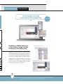
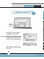
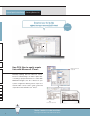
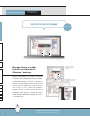
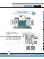
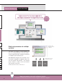
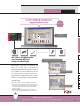
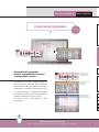
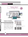
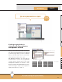
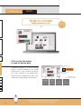
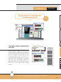
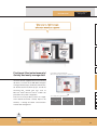
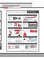
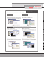
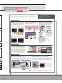
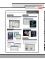
Mitsubishi iQ Platform Compatible
FA Integrated Engineering Software
MELSOFT iQ Works
Introducing
MELSOFT Navigator
Navigating to an intuitive engineering environment
Mitsubishi Electric FA Integrated Concept
Engineering innovations start from
MELSOFT Navigator
Is selecting modules time consuming?
Is setting the parameters for multiple systems bothersome?
Are you manually inputting your device list?
Are you connecting a cable to each device to backup your system?
Is it difficult to search for project data during maintenance?
Here’s a more interactive and visible engineering style.
Revolutionizing everything from the way you design system specifications
and develop programs, to the way you perform field adjustments,
operations, and maintenance.
Experience the ease-of-use
MELSOFT Navigator
Seamless integrated engineering environment to accelerate total cost reduction
MELSOFT iQ Works
System Management Software
MELSOFT Navigator
MELSOFT Navigator, along with GX Works2, MT
Works2, GT Works3, and RT ToolBox2, facilitates
system level design and acts as the interface
between each software. Useful functions include
design of system configuration, parameter batch
setting, system labels, and batch read.
Redefining engineering with
Programmable Controller
Engineering Software
Motion Controller
Engineering Software
MELSOFT Navigator
HMI/GOT
Screen Design Software
Robot Engineering Software
MELSOFT GX Works2 MELSOFT MT Works2 MELSOFT GT Works3 MELSOFT RT ToolBox2
This is the main programming and maintenance
software for the PLC.
Incorporating legacy support
of programs created with GX
Developer, further improving
its functionality resulting in
reduced engineering costs.
The motion control design
and maintenance software
includes intuitive graphic
based programming together
with a digital oscilloscope
simulator, further helping to
reduce a motion systems
TCO.
The GOT (Graphic Operation
Terminal) screen creation
software has been designed
with 3 main features;
Simplicity, Graphic Design,
and Easy Usability, further
helping to create graphic
screens in fewer steps.
The robot setup software supports
various steps from programming, to
commissioning, evaluation, and
maintenance. In addition to
improving preventative maintenance
by using the integrated 3D evaluation
simulator to visualize parameterization and connected devices.
Ease-of-use at your fingertips
MELSOFT Navigator
System Specifications Design
Module Selection
05
Displays available options in a list. Easily arrange suitable modules in the workspace.
Checking Power Supply Capacity/Number of I/O Points
06
No need to look up manuals. Automatic check is available in module configuration.
Creating Device List
07
Use CSV files to easily create lists with Microsoft ® Excel ®.
Creating System Configuration
08
Directly apply your system designs in different locations.
Managing reference documentations
09
Manage files in a similar fashion as in Microsoft ® Windows ® desktop.
Motion System Templates
10
Templates with preset parameters and labels are available.
Program Development
Parameter Batch Setting
11
Batch set parameters for multiple systems.
Sensor Parameter Setting
12
Set parameters for the iQSS compatible sensor from within the same setup screen.
Parameter Setting
13
Setup of devices on CC-Link/AnyWireASLink network without needing a manual.
Device Assignment
14
Graphical based device configuration by automatically assigning of devices.
Label Sharing
15
Changes are automatically reflected in all related projects.
Field Adjustments
Multiple Device Data Backup
16
Read out project data for multiple devices in batch.
Maintenance
Project Data Maintenance
18
Finding required data is a breeze with the workspace management method.
Maintenance Software Automatic Startup
20
The right software automatically starts up.
Management of older sequence program
21
Sequence programs for older equipment can be managed together.
Instruction Manual Management
22
Find target files instantaneously! Quickly and easily manage data.
MELSOFT iQ Works products
23
FAQ
27
Main Specifications
28
Compatible Module List
29
Automation related products
33
System Specifications Design Module Selection
You’ll be amazed at how quickly
you can select the most suitable module.
Displays available options in
a list. Easily arrange suitable
modules in the workspace.
Convenient!
Available modules are listed
Catalogs to read, web sites to check. The first
time-consuming task in designing a system is
selecting the modules. With MELSOFT Navigator,
all of current available modules are listed, and the
specifications of selected modules can be easily
confirmed. This simplifies the module selection
process. Pick the most suitable module and drag
Selected module is illustrated
& drop it into the system configuration.
POINT
Complete the system configuration just by dragging & dropping modules!
5
The module list shows all modules including special I/O modules.
System Specifications Design
Checking Power Supply Capacity/
Number of I/O Points
The power supply capacity and number of I/O points are automatically
checked, so you don’t need to rely on the manual!
No need to look up manuals.
Automatic check is available
in module configuration.
Time saving!
Module configuration drawing
Until now, referencing the manual was essential
for calculating power supply capacity and looking
up number of I/O points. Since making new
selections in case of a mistake is bothersome,
users often select extra large power supplies and
CPU modules.
Automatic check of power supply capacity/Number of I/O points
With MELSOFT Navigator, power supply capacity
and number of I/O points of the selected module
are automatically checked for the selected
module configuration. This makes it easy to
change the power supply and CPU modules
when necessary.
POINT
Select the appropriate power supply capacity and number of I/O points!
With automatic check, power supply modules and CPU modules can be re-selected easily.
6
System Specifications Design Creating Device List
Document your device lists
without having to manually input data!
Use CSV files to easily create
lists with Microsoft Excel .
®
Output CSV file from
module list
®
Manually inputting data into Microsoft ® Excel ®
based on CAD drawings can make it quite timeconsuming to prepare device lists for orders. With
MELSOFT Navigator, the list of devices in your
system configuration drawing can be output as a
CSV file which can be used to easily create and
output device lists with Microsoft ® Excel ®.
Create device list with
Microsoft ® Excel ®
Print out the device list
POINT
Make it easier to order modules!
7
Easy!
No longer create device lists with manual inputs.
System Specifications Design
Creating System Configuration
Effortlessly create system configurations without
using Microsoft ® Visio ® or Microsoft ® Word ®!
Directly apply your system
designs in different locations.
Convenient!
System configuration
Documenting your system configuration takes
time and manpower. Do you still manually input
your network configurations, module configurations and parameters settings with Microsoft ®
Visio ® or Microsoft ® Word ®?
Design your system using MELSOFT Navigator
and reuse the design details in other documents.
There is no need to start from scratch each time.
Paste into
Microsoft ® Word ®
Edit and print with
Microsoft ® Word ®
POINT
Incorporate design details into other documents!
Reuse everything from network configurations, module configurations and parameter settings.
8
System Specifications Design
Managing reference
documentations
All relevant data are one-click away!
Convenient!
Manage files in a similar
fashion as in Microsoft
Windows desktop.
Paste the link file for
reference and design
documents
®
®
Saving and managing vast amounts of reference
documents used for designing is always a headache.
In MELSOFT Navigator, link files to mechanical
drawings and past design materials can be pasted
into the system configuration. To open the file, just
click on the icon as in a Microsoft ® Windows ®
desktop. There is no need to search for each file
individually. With link files to design documents
readily available, MELSOFT Navigator becomes a
convenient portal.
POINT
A portal to design documents!
9
Insert link files to design documentations.
Click and open
target files
System Specifications Design
Motion System
Templates
Advanced multi-CPU settings are so easy
when you use templates!
Templates with preset
parameters and labels are
available.
Easy!
Use templates with preset parameters and labels
Just as settings for a programmable controller
CPU can be complicated, so can settings for a
motion controller. MELSOFT Navigator provides
multiple templates to facilitate setting up multiCPU configurations that include a programmable
controller CPU and a motion controller. The
parameters and labels are preset, allowing you to
focus on the programming.
Programmable
controller CPU
(GX Works2)
Motion
controller
(MT Works2)
POINT
Set up a multi-CPU configuration in a short time!
No need to configure motion control from scratch!
10
Program Development
Parameter Batch Setting
Apply parameters from the system configuration to
each station’s programmable controller/GOT in one shot!
MELSOFT
collaboration!
Batch set parameters for multiple
systems.
Parameter setting
information in system
configuration
Just when you thought you were finished, you
have to set the parameters for the next system...
In the programming stage, setting the parameters
for multiple systems is bothersome.
With MELSOFT Navigator, the information set in
Applied in batch onto each
development tool’s data
the system configuration is applied in batch onto
each GX Works2, MT Works2 or GT Works3
project. There’s no need to start each software
and check the consistency.
✽ Detailed parameters must be set with each tool.
Programmable
controller
(GX Works2)
Motion
controller
(MT Works2)
GOT
(GT Works3)
POINT
Apply parameters onto each software in batch!
11
Parameters are automatically generated from network configuration and module configuration.
Program Development Sensor Parameter Setting
No need to individually setup each sensor
using proprietary setup tools
Convenience!
Connect and
view with One Tool!
One Tool to set parameters
even between different
sensor manufacturers
Automatically generate the system configuration
diagram by detecting connected sensors
Setting parameters for each sensor can be difficult as setting
methods can vary between setup tools. However, by using
MELSOFT Navigator and GX Works2, the parameters for different
iQSS✽1 compatible sensors can be setup all from the same setup
Select the sensor icon to
set with unified operations
screen. There’s no need to use a dedicated tool for each sensor,
resulting an efficient way of setting various sensors all in one operation.
In addition, sensors supporting CC-Link and AnyWireASLINK✽2
networks, can be detected automatically within the system
configuration diagram.
✽ 1 Innovative solution for reducing TCO. iQ Sensor Solution
✽ 2 Sensor network that centrally monitors (visualizes) the sensor
statuses from the programmable controller, and contributes to
improving operating rates and reducing engineering time.
✽ 3 Refer to the iQSS catalog for further details. (Sensor Solution
iQ Sensor Solution)
✽ 4 AnyWireASLINK products are not available in some countries.
Please consult your local Mitsubishi Electric representative for details.
Set parameters for different
sensors on one screen
POINT
Reduce sensor setup time!
Automatic detection of connected sensors within the system configuration diagram.
12
Program Development Parameter Setting
Can you really set the CC-Link/AnyWireASLINK network
without referring to a manual?!
Easy!
More than 400 types of
CC-Link remote I/Os, GOTs,
inverters and robots are supported!!
POWER
Just select the device,
ready for the design stage!
MODE
RUN
ERR.
USER
BAT.
BOOT
USB, etc.
MODE
RUN
ERR.
USER
BAT.
BOOT
MODE
RUN
ERR.
USER
BAT.
BOOT
←
←
PULL
PULL
PULL
←
←
←
CC-Link
PULL
USB
USB
USB
RS-232
RS-232
RS-232
←
Mitsubishi CC-Link master station
MELSOFT Navigator and GX Works2 use drag &
Select
“Slave station parameter process”
drop and graphic based screens to create a intuitive
setting environment for the CC-Link / AnyWireASLINK
network. Easy operations mean the process from
setting the various parameters to automatic calculation
of the link scan time can be carried out at once. In
Automatically calculates
link scan time
addition, the slave station parameters settings can
be confirmed and changed when required. New
Slave station’s
parameter setting window opens
modules can be added to CC-Link by installing the
CSP+✽1 released from CLPA✽2.
✽ 1 CC-Link Association
✽ 2 Profile prepared by vendors developing CC-Link family
compatible products
✽ 3 GX Works2 also supports CC-Link IE Field.
Set slave station’s
parameters!
POINT
Easily set the master and slave stations without mistakes!
13
Set each device without a manual.
Program Development Device Assignment
No need to consider device addresses!
Easy!
Automatically generate
device assignments from the
configuration screen.
By using the new CC-Link configuration editor as
part of the GX Works 2 package, device assignment
Create the device
configuration with the
configuration editor
Automatically generate
a list of device
assignments
tasks have been made much simpler. Just rearrange
the illustrations on the editor screen using the mouse
to complete the device configuration and finish
programming. The devices are then automatically
assigned and listed in an easy-to-view list.
Program the ladder
diagram while viewing
the device assignments.
This feature can be easily utilized for label
programming.
POINT
Making programming easier!
Easily and efficiently complete processes from device configuration to programming.
14
Program Development
Label Sharing
Assign devices for multiple projects
just by changing one setting!
MELSOFT
collaboration!
Changes are automatically
reflected in all related projects.
Define labels from
one location
In the past, if the device assignments changed,
the same corrections had to be made for each of
the projects. This problem has been resolved by
using MELSOFT Navigator which can share labels
between the programmable controller, motion
Changes in settings are automatically
applied to each project
controller and GOT. If, for example, a device
assignment is changed in a programmable
controller project, those changes are automatically
applied on the motion controller and GOT projects.
This greatly reduces setting time and setting
Programmable
controller
(GX Works2)
Motion
controller
(MT Works2)
GOT
(GT Works3)
mistakes.
POINT
Greatly reduce man-hours spent changing settings!
15
Use system labels to efficiently apply changes throughout the entire system.
Multiple Device
Data Backup
Field Adjustments
Can you really backup multiple devices
without connecting cables to each one?
MELSOFT
collaboration!
Read out project data for
multiple devices in batch.
Cable connection to
programmable controller
(master station, etc.)
Programmable controller, motion controller and
GOT... The more equipment you connect to the
Read project
data in batch
system, the longer it takes to read out project data
for backup. With MELSOFT Navigator, if a cable is
connected to the master station’s programmable
controller, to which multiple devices are connected
via
bus
or
network
(MELSECNET/CC-Link
IE/Ethernet), the project data for the multiple
devices can be read out in batch. It is unnecessary
to connect cables to each device.
Programmable controller
Motion controller
GOT
POINT
Read from multiple devices with one single cable!
There is no need to individual connect to each device.
16
Multiple Device
Data Backup
Field Adjustments
No more operation mistakes
or overdue backups!
MELSOFT
collaboration!
Read in batch without starting
each software.
<Conventional>
Previously, to read out each device's project data,
GX Works2
MT Works2
the operator had to start up each software (GX
Works2, MT Works2, GT Works3), read from the
GT Works3
Start each
software
project file, and then read data from the device.
This process took several minutes per device. As
the number of connected devices increased, the
possibility of operation mistakes and overlooked
Read from
project data
backups increased. Now, with MELSOFT Navigator, after initial connections are defined for each
software, data can be batch read without having to
start up each software. This dramatically improves
the efficiency of periodic backups and prevents
data from being missed.
POINT
Efficiently backup data periodically with no mistakes!
17
Batch read project data for multiple devices without complicated procedures.
Read from
each device
Project Data
Maintenance
Maintenance
Find the desired project data at a glance!
MELSOFT
collaboration!
Finding required data is
a breeze with the workspace
management method.
Manage project data with workspaces
Have you ever felt that when folders are made for
Display project names with tree structure
each process and managed in nests, it’s still hard
to find that project data you want to maintain?
Once you find the folder, there are several files,
and you don’t know which one to open.
With MELSOFT Navigator, the project data for
several devices such as the programmable
Search for corresponding project
controller, motion controller, GOT or robot can be
managed as workspaces for a factory or a line.
The project names are displayed with a tree struc-
Click to read data
Programmable
controller
(GX Works2)
Motion
controller
(MT Works2)
GOT
(GT Works3)
Robot
(RT ToolBox2)
ture in the workspace, and you can use Explorer to
quickly find the project you need, etc.
POINT
No longer manage with project names!
As easy as searching for the project name in the workspace!
18
Maintenance
Project Data
Maintenance
Illustration of the system expedites
finding the device you need!
MELSOFT
collaboration!
Click on the illustration
to read its device data.
Paste-able bitmap and
text box
In MELSOFT Navigator, you can insert bitmap
images to facilitate visualization of the system,
and text boxes to write comments. The illustra-
Visually search for the
desired device
tions make searching for the desired device
intuitive and fast. Reading project data is also
Read data by clicking
the device illustration
made easy by simply clicking on the illustration.
Programmable
controller
(GX Works2)
Motion
controller
(MT Works2)
GOT
(GT Works3)
POINT
Perform intuitive searches with illustrations!
19
Paste bitmaps and text boxes into system configuration.
Robot
(RT ToolBox2)
Maintenance Software
Automatic Startup
Maintenance
How easy! Click on the corresponding project
to start up the right software!
The right software automatically
starts up.
MELSOFT
collaboration!
Click on a project in the workspace tree
Software for
corresponding
device automatically
starts up
Various software, including GX Developer, GX
Works2, MT Works2, GT Works3 and RT ToolBox2,
Click on a device in the system configuration
GX Works2
are used to edit project data used in a factory or
line. It is often hard to know which software to start
MT Works2
up. With MELSOFT Navigator, clicking on a project
listed in the system configuration or workspace
tree, starts up its corresponding software. The
GT Works3
MELSOFT iQ Works Suite includes the license for
these tools so you no longer need to manage
RT ToolBox2
licenses.
POINT
Maintain your devices without worrying about software!
The correct software automatically starts up.
20
Maintenance
Management of older
sequence program
Hassle-free management covers programs
even for older equipment.
Sequence programs for older
equipment can be managed
together.
MELSOFT
collaboration!
Start GX Developer from
workspace tree
Are you having trouble managing your sequence
programs for older equipment? With MELSOFT
Navigator, you can work with GX Developer which
is capable of editing A Series✽ sequence programs.
Even when using systems consisting of older and
newer programmable controllers, the project data
for each programmable controller can be managed
together with MELSOFT Navigator.
✽ Excludes some modules.
POINT
Compatible with GX Developer!
21
Use GX Developer to edit A Series✽ sequence programs.
Manage data for equipment
using older A Series
Maintenance
Instruction Manual
Management
From now on, find the target
instruction manual at a glance!
Find target files instantaneously!
Quickly and easily manage data.
Insert link files to documents and data
(Microsoft ® Word ®, Microsoft ® Excel ® and PDF, etc.)
It’s hard to find the equipment’s instruction manual
file when you need it most. MELSOFT Navigator
manages GX Developer, GX Works2, MT Works2,
GT Works3 and RT ToolBox2 project, and allows
document files created with tools such as
Microsoft ® Word ®, Microsoft ® Excel ® or PDF to be
pasted into the system configuration.
Create a portal site of equipment-related documents
Click to display the target instruction file
This ease-of-use is just like a portal tool for equipment related documents. Greatly improve the
efficiency of design document and instruction
Microsoft ® Word ®
file
Microsoft ® Excel ®
file
PDF
file
manual data management.
POINT
Handy tool for operators!
Equipment related documents including instruction manuals can be easily searched and referred to by anyone.
22
MELSOFT iQ Works
MELSOFT GX Works2
MELSOFT MT Works2
MELSOFT Navigator
MELSOFT GT Works3
MELSOFT RT ToolBox2
Programmable Controller Engineering Software
Completely updated user interface improves your design efficiency.
Integrating simulation functions with configuration functions!
In addition to
programmable
controller programming, GX Works2
integrates simulation
and various
intelligent module
setting functions.
No need to purchase GX Simulator and GX Configurator separately.
[ Integration of simulation function ]
[ Integration of configuration function ]
The simulator can be started easily with a single button allowing debugging
in the same circumstances as online even without an actual machine.
By opening the setting screen from the project window, the
parameters for each module can be set easily on the screen.
<Analog/Digital converter module>
No need to wire a programmable
Double-click
<Positioning module>
controller mounted device!
Debugging can be started with a personal Operations can be confirmed while viewing
computer immediately after designing even movements on a personal computer so
without wiring a programmable controller. designs can be completed without reworking.
Reduce operation steps and input mistakes with candidate displays!
Input options are
automatically listed during
command and label inputs.
When inputting in an inline
ST, label and command
options are displayed.
MELSOFT GX Works2
Explanation of input options
Explanation of argument type
Automatic display of input options
Explanation of label
Easily perform continuous searches of devices with user-friendly operations!
Directly write operations into ladders with inline ST!
Operation processes can
be written directly in the
ladder program.
There’s no need to add
multiple lines of ladders
or function blocks.
Identify similar devices in a glance!
Comments can be set for
each bit and for word
devices.
Read mode supports quick
searches. Perform a continuous
search by pressing the Enter key.
➊
Batch replacement of
label names is possible
➋
A comment can be set for a bit-specified
word device and displayed on the ladder
circuit.
➌
Continuous search function
F keys to search the first “Auto” When the search option is designated, a continuous
Press Ctrl
Press the Enter key to search the next “Auto” (cursor moves) search is made each time the Enter key is pressed.
Quickly find where the device is being used!
Cross reference information for
the device pinpointed with the
cursor is automatically displayed.
One-touch displayable help function!
Help for the selected command
is displayed immediately when
the F1 key is pressed.
<Cross reference>
Help display
PRESS!
F1
Double click to jump to where the device is used in another program
Making it easier to use intelligent function modules through buffer memory and I/O signal comments!
For special relays and special registers
For intelligent function module
The intelligent function’s
buffer memory and X/Y
comments are supported.
Easily apply predefined comments from the right-click menu.
Refer to the GX Works2 Catalog <L(NA)08122E> for details.
23
MELSOFT iQ Works
MELSOFT GX Works2
MELSOFT MT Works2
MELSOFT Navigator
MELSOFT GT Works3
MELSOFT RT ToolBox2
Motion Controller Engineering Software
Intuitive operations on graphical screens. Smoothly set even large-scale programs.
Programming
System Design
Motion controller programming is supported with various
convenient functions.
Graphical motion SFC program and mechanical system program
Label, device comment and cross-reference
Command wizard and Instruction help allow you to program without a manual.
Startup and Adjustment
MELSOFT MT Works2
Easily set servo amplifiers and modules on the graphical
system setting screen. Parameters also can be set quickly
without a manual by checking One-point help.
Supporting startup of the servo system with diverse functions.
Variety of monitor function
Digital oscillation function
A vast array of monitor functions allow the operation status of
the motion controller to be confirmed easily.
Data which is synchronized with the motion operation cycle can be collected and
displayed. It is possible to set the requested data simply with specified purpose probe
setting. Collected data can be saved in CSV format and analyzed with other tools.
Various test operation functions
Collaboration with MR Configurator2
In the test mode, basic startup can be confirmed without a program. Using the
simulator function, theoretical debugging can be performed without an actual machine.
In addition, the debug function is capable of step execution and break point settings.
Use the servo setup software “MR Configurator2”, filled with Mitsubishi
Electric’s servo knowhow, to adjust your servo system effortlessly. Multi-axes
servo system can also be adjusttuned via motion controller from PC.
24
MELSOFT iQ Works
MELSOFT GX Works2
MELSOFT Navigator
MELSOFT MT Works2
MELSOFT GT Works3
MELSOFT RT ToolBox2
Screen Design Software
MELSOFT GT Works3
Such easy steps from “New Screen” to “Transfer to GOT”.
Screen Creation
“Templates” reduce screen creation steps
“Data Browser” simplifies setting confirmation and revisions
“Help Function” shows the information you need
Common screens and parts have been prepared
as templates. Adjust these templates to quickly
and easily create screens to match your target
and applications with fewer screen creation steps.
The settings for graphics used in the
project are all listed.
When the F1 key is pressed, help for the
currently active dialog opens immediately!
Easily check the information you need.
<Changing the color>
All colors for template attribute
“No. 1 color” are changed in batch!
Edit directly in the list or edit
from a setting dialog.
Double-click
When the
key is pressed
on the Lamp Setting screen
When the
key is pressed
on the Lamp Setting screen
Setting method
is displayed
Template attribute “No. 1 color”
Change color
includes:
Historical trend graph line colors
Numerical display value colors Character colors
<Device monitor (bit)>
Table of Contents is displayed
The device list for the connected devices
being set is displayed.
There’s no need to open your manual!
<Historical (graph + list)>
Search the information you Related items are also
displayed
need from the Table of
Contents or keyword
Security Control
1. Set different access
authority for each screen
The User (OEM/End User) Security Function prevents
your valuable data from being leaked or changed!
Setting for
base screen 2
Protect your project data by setting access authority (availability
of displaying and editing a project) with a five-stage access
level not only for the project but also for screens. When the
several people are involved in designing the screen, a specific
screen can be protected by setting different access authority for
each screen. The availability of displaying or editing the project
can be confirmed with the work tree or the screen image list.
Editing prohibited screen
Setting for
base screen 3
3. Base screen 2: Display permitted, editing prohibited
Base screen 3: Display prohibited, editing prohibited
2. Login with a user whose access
level is Developers (Level 1)
Display prohibited screen
If the access level of the logged-in user is Developers (Level 2),
base screens 2 and 3 can be displayed and edited.
Simulation
Confirm operations with a single click
Simple simulation with “Screen Preview”
Screen data movements (alarm confirmations, screen transitions
and device monitoring, etc.) can be confirmed on your personal
computer. Efficiently debug while correcting your screen.
Simple simulations and screen changeovers can be confirmed with screen
preview. A specific switch display can be turned ON and OFF, device
values can be input, and random screen images can be printed and saved,
making it easy to prepare specifications and operation procedures.
Communication/Monitor
GT Works3 Simulation function
GT Works2 Simulator (virtual programmable controller)
➊
<Confirming screen change switch>
Execute designated program
➋
SM411
➌
[+ K1 D201]
Screens can be changed on the
screen preview. The editing screen
can be opened in sequence with
the preview screen so corrections
can be made quickly while
confirming on the preview screen.
[MOV K0 D200]
M1
M0
➊ Start simulator
➋ Click with mouse to touch
➌ Device values and ON/OFF states can be changed.
When the screen has been
revised, just click “Update”!
Screen changes when the screen
change switch is clicked.
Refer to the GT Works3 Catalog <L(NA)08170ENG> for details.
25
MELSOFT iQ Works
MELSOFT GX Works2
MELSOFT MT Works2
MELSOFT Navigator
MELSOFT GT Works3
MELSOFT RT ToolBox2
Robot Engineering Software
Total support from program creation, to start up, adjustment and maintenance.
Programming
MELSOFT RT ToolBox2
Setting
Program editing
3D Viewer
• Create programs with MELFABASIC IV, V or Movemaster languages.
• Efficiently perform work with multi-window method.
• With instruction templates and help functions, there’s no
need to refer to manuals.
Visually confirm the limit values for the user defined areas,
etc., with 3D Viewer.
Startup and Adjustment
Use 3D Viewer to confirm the robot’s posture and motions, and
to virtually arrange the peripheral devices with basic objects.
Debugging function
A variety of convenient functions make it easy to confirm operations such
as program step execution, break point setting and direct execution.
Maintenance
Monitor function
Monitor the program execution state, variables and input/output signals, etc. In
addition, monitor the servo statuses such as the axis load status and current value.
Maintenance function
• Various maintenance functions include the maintenance forecast
function that notifies operators of the robot grease up timing and
battery consumption time, etc., and functions to restore the
position in the event of trouble. These functions are effective for
preventive maintenance and for shortening the recovery time.
• The entire system can be backed up in a batch using the
project unit data control.
26
Frequency Asked
Questions
FAQ
Contact information
Lineup
27
Q
A
Who do we consult with to make a purchase?
Q
A
Who do we contact for information on the product technology?
Q
A
Our personal computers use DVD. Is MELSOFT iQ Works available on DVD?
Contact your nearest Mitsubishi Electric branch office or dealer.
Contact your nearest Mitsubishi Electric branch office or dealer.
Please see the back cover for contact information.
MELSOFT iQ Works is available on CD and DVD. Select the medium which works on your system.
Main Specifications
List of Software Functions
Model
Outline
Mitsubishi Electric iQ Platform compatible
FA Integrated Engineering Software suite with Additional Integrated Functions, CD-ROM Version
Mitsubishi Electric iQ Platform compatible
System Management Software [MELSOFT Navigator]
SW1DNC-IQWK-E
+ Mitsubishi Electric iQ Platform compatible
Programmable Controller Engineering Software [MELSOFT GX Works2]
+ Mitsubishi Electric iQ Platform compatible
Motion Controller Engineering Software [MELSOFT MT Works2]
+ Mitsubishi Electric iQ Platform compatible
Screen Design Software [MELSOFT GT Works 3]
+ Mitsubishi Electric iQ Platform compatible
Robot Engineering Software [MELSOFT RT ToolBox2 mini]
Mitsubishi Electric iQ Platform compatible
FA Integrated Engineering Software suite with Additional Integrated Functions, DVD-ROM Version
MELSOFT iQ Works
iQ Platform
compatible
FA Integrated
Engineering
Software
Mitsubishi Electric iQ Platform compatible
System Management Software [MELSOFT Navigator]
SW1DND-IQWK-E
+ Mitsubishi Electric iQ Platform compatible
Programmable Controller Engineering Software [MELSOFT GX Works2]
+ Mitsubishi Electric iQ Platform compatible
Motion Controller Engineering Software [MELSOFT MT Works2]
+ Mitsubishi Electric iQ Platform compatible
Screen Design Software [MELSOFT GT Works 3]
MELSOFT GX Works2
SW1DNC-GXW2-E
MELSOFT MT Works2
SW1DNC-MTW2-E
MELSOFT GT Works3
SW1DNC-GTWK3-E
MELSOFT RT ToolBox2
3D-11C-WINE
3D-12C-WINE
+ Mitsubishi Electric iQ Platform compatible
Robot Engineering Software [MELSOFT RT ToolBox2 mini]
MELSEC Programmable Controller Programming
SW Programming Function + Intelligent Module Function + Simulator Function
Mitsubishi Electric iQ Platform compatible Motion Controller Engineering Software
Screen Design Software for GOT
+ Simple Data Conversion Function + GT SoftGOT 1000 Function + Simulator Function
Robot Engineering Software with Simulation Function CD-ROM Version
Robot Engineering Software mini Simple Version CD-ROM Version
MELSOFT iQ Works operation environment
Microsoft® Windows® 2000 Professional Service Pack4
Microsoft® Windows® XP Professional Service Pack2,3
Microsoft® Windows® XP Home Edition Service Pack2,3
Microsoft® Windows® Vista® Home Basic Service Pack1,2
OS ]
Microsoft® Windows® Vista® Home Premium Service Pack1,2
Microsoft® Windows® Vista® Ultimate Service Pack1,2
Microsoft® Windows® Vista® Business Service Pack1,2
Microsoft® Windows® Vista® Enterprise Service Pack1,2
CPU
Desktop: Celeron 2.8 GHz or more recommended
Memory
1 GB or more recommended
Display
XGA (1024×768) or more
Free space
At installation: HD1GB (+ 390MB when installing manual) ] 32-bit OS supported. Microsoft® Windows® 7 and Microsoft® Windows® 8 supported with 64-bit version.
Details
Microsoft® Windows® 7 Ultimate Service Pack1
Microsoft® Windows® 7 Enterprise Service Pack1
Microsoft® Windows® 7 Professional Service Pack1
Microsoft® Windows® 7 Home Premium Service Pack1
Microsoft® Windows® 7 Starter Service Pack1
Microsoft® Windows® 8
Microsoft® Windows® 8 Pro
Microsoft® Windows® 8 Enterprise
Laptop personal computer: PentiumM 1.7 GHz or more recommended
During operation: 512 MB of free virtual memory
MELSOFT iQ Works compatible version
Details
MELSOFT GX Works2
MELSOFT MT Works2
MELSOFT GT Works3
MELSOFT RT ToolBox2
Version 1.492N and higher
Version 1.62Q and higher
Version 1.74C and higher
Version 2.50C and higher
28
MELSOFT Navigator Compatible Module List
Compatible Networks
Category
Ethernet
MELSECNET/H
CC-Link IE Controller Network
CC-Link IE Field Network
CC-Link
AnyWire ASLINK
Main base
Slim type main base
Redundant power supply main base
Base module
Extension base
Compatible Programmable Controller (MELSEC-Q Series)
Category
Basic model QCPU
High-performance model QCPU
Universal model QCPU
CPU
Motion CPU
C Controller CPU
Base module
Main base
Model
Q00JCPU
Q00CPU
Q01CPU
Q02CPU
Q02HCPU
Q06HCPU
Q12HCPU
Q25HCPU
Q00UJCPU
Q00UCPU
Q01UCPU
Q02UCPU
Q03UDCPU
Q03UDECPU
Q03UDVCPU
Q04UDHCPU
Q04UDEHCPU
Q04UDVCPU
Q06UDHCPU
Q06UDEHCPU
Q06UDVCPU
Q10UDHCPU
Q10UDEHCPU
Q13UDHCPU
Q13UDEHCPU
Q13UDVCPU
Q20UDHCPU
Q20UDEHCPU
Q26UDHCPU
Q26UDEHCPU
Q26UDVCPU
Q50UDEHCPU
Q100UDEHCPU
Q172CPUN
Q172CPUN-T
Q173CPUN
Q173CPUN-T
Q172HCPU
Q172HCPU-T
Q173HCPU
Q173HCPU-T
Q172DCPU
Q173DCPU
Q172DSCPU
Q173DSCPU
Q06CCPU-V
Q12DCCPU-V
Q33B
Q35B
Q38B
Q312B
Q35DB
Redundant power supply extension base
Power supply module
Power supply
module
Slim type power supply
Redundant power supply
Input
I/O module
Output
Model
Q38DB
Q312DB
Q32SB
Q33SB
Q35SB
Q38RB
Q63B
Q65B
Q68B
Q612B
Q52B
Q55B
Q68RB
Q61P
Q61P-A1
Q61P-A2
Q61P-D
Q62P
Q63P
Q64P
Q64PN
Q61SP
Q63RP
Q64RP
QX10
QX10-TS
QX28
QX40
QX40-TS
QX40-S1
QX40H
QX41
QX41-S1
QX41-S2
QX42
QX42-S1
QX50
QX70
QX70H
QX71
QX72
QX80
QX80-TS
QX80H
QX81
QX81-S2
QX82
QX82-S1
QX90H
QY10
QY10-TS
QY18A
QY22
QY40P
QY40P-TS
QY41H
QY41P
QY42P
QY50
QY68A
QY70
QY71
QY80
] Above listed modules are compatible with MELSOFT Navigator (Ver. 1.62Q).
These modules differ from the MELSOFT GX Works2, MELSOFT MT Works2, MELSOFT GT Works3 and MELSOFT RT ToolBox2 compatible modules.
29
MELSOFT Navigator Compatible Module List
Compatible Programmable Controller (MELSEC-Q Series)
Category
Output
I/O module
I/O
Interrupt input
Analog input
Analog output
Analog I/O
module
Temperature input
Temperature control
Loop control
Simple
motion
Positioning
With SSCNET #/H
connectivity
Category
Model
QY80-TS
QY81P
QY82P
QH42P
QX48Y57
QX41Y41P
QI60
Q68ADV
Q62AD-DGH
Q68ADI
Q64AD
Q64ADH
Q64AD-GH
Q64AD2DA
Q68AD-G
Q66AD-DG
Q61LD
Q68DAVN
Q68DAV
Q68DAIN
Q68DAI
Q62DAN
Q62DA
Q62DA-FG
Q64DAN
Q64DA
Q64DAH
Q66DA-G
Q64RD
Q64RD-G
Q68RD3-G
Q64TD
Q64TDV-GH
Q68TD-G-H01
Q68TD-G-H02
Q64TCRT
Q64TCRTBW
Q64TCTT
Q64TCTTBW
Q64TCRTN
Q64TCRTBWN
Q64TCTTN
Q64TCTTBWN
Q62HLC
Q68CT
QD77MS2
QD77MS4
QD77MS16
QD72P3C3
QD73A1
QD75P1
QD75P2
QD75P4
QD70P4
QD70P8
QD75D1
QD75D2
QD75D4
QD70D4
QD70D8
QD75M1
QD75MH1
Positioning
High-speed counter
Channel isolated pulse input
Energy Measuring
Isolation monitoring
Web Server
MES interface
High-speed data logger
Ethernet
Serial communication
Intelligent communication
Optical loop (SI)
MELSECNET/H
Optical loop (GI)
Coaxial bus
Twisted bus
CC-Link
CC-Link/LT
Ver. 2.00
FL-net
(OPCN-2)
Ver. 1.00
AS-i
CC-Link IE Controller Network
CC-Link IE Field Network
AnyWireASLINK
Servo external signal input
Motion
module
Synchronous encoder input
(synchronization between master/slave)
Manual pulse generator input
Partner
products
Displacement sensor control
Model
QD75M2
QD75MH2
QD75M4
QD75MH4
QD74MH8
QD74MH16
QD62
QD62-H01
QD62-H02
QD62D
QD62E
QD63P6
QD64D2
QD65PD2
QD60P8-G
QE81WH
QE81WH4W
QE83WH4W
QE84WH
QE82LG
QJ71WS96
QJ71MES96
QD81DL96
QJ71E71-100
QJ71E71-B2
QJ71E71-B5
QJ71C24N
QJ71C24N-R2
QJ71C24N-R4
QD51
QD51-R24
QJ71LP21-25
QJ71LP21S-25
QJ71LP21G
QJ71BR11
QJ71NT11B
QJ61BT11N
QJ61CL12
QJ71FL71-T-F01
QJ71FL71-B2-F01
QJ71FL71-B5-F01
QJ71FL71-T
QJ71FL71-B2
QJ71FL71-B5
QJ71AS92
QJ71GP21-SX
QJ71GP21S-SX
QJ71GF11-T2
QJ51AW12AL
Q172LX
Q172DLX
Q172EX
Q172EX-S1
Q172EX-S2
Q172EX-S3
Q172DEX
Q173PX
Q173PX-S1
Q173DPX
UQ1-01
UQ1-02
] Above listed modules are compatible with MELSOFT Navigator (Ver. 1.62Q).
These modules differ from the MELSOFT GX Works2, MELSOFT MT Works2, MELSOFT GT Works3 and MELSOFT RT ToolBox2 compatible modules.
30
MELSOFT Navigator Compatible Module List
Compatible Programmable Controller (MELSEC-L Series)
Category
CPU
Branch / Extension module
Power supply
RS-232 adaptor
End cover
With error terminal
Input
I/O module
Output
Analog I/O
Temperature Control
Simple motion
Positioning
High-speed counter
Network
CC-Link IE Field Network
CC-Link
CC-Link/LT
Ethernet interface
Serial communication
AnyWireASLINK
Compatible Programmable Controller (MELSEC-FX Series)
Model
L02SCPU
L02SCPU-P
L02CPU
L02CPU-P
L06CPU
L06CPU-P
L26CPU
L26CPU-P
L26CPU-BT
L26CPU-PBT
L6EXB
L6EXE
L61P
L63P
L6ADP-R2
L6EC
L6EC-ET
LX10
LX28
LX40C6
LX41C4
LX42C4
LY10R2
LY20S6
LY41NT1P
LY42NT1P
LY40NT5P
LY40PT5P
LY41PT1P
LY42PT1P
L60AD4
L60AD4-2GH
L60DA4
L60TCRT
L60TCRTBW
L60TCTT
L60TCTTBW
LD77MH4
LD77MH16
LD75P1
LD75P2
LD75P4
LD75D1
LD75D2
LD75D4
LD62
LD62D
LJ71GF11-T2
LJ61BT11
LJ61CL12
LJ71E71-100
LJ71C24
LJ71C24-R2
LJ51AW12AL
CPU
Special block
Category
FX3G Series CPU
FX3U Series CPU
FX3UC Series CPU
Ethernet block
Model
FX3G-✽✽M
FX3U-✽✽M
FX3UC-✽✽M
FX3U-ENET✽
Compatible display
Category
GOT 1000 Series
Model
GT16✽✽-X
GT16✽✽-S
GT16✽✽-V
GT165✽-V
GT15✽✽-X
GT15✽✽-S
GT15✽✽-V
GT155✽-V
GT15✽✽-Q
GT14✽✽-Q✽BD
GT14✽✽-Q✽BDE
(Ethernet built-in)
GT12✽✽-V
GT11✽✽-Q
GT11✽✽-Q✽BDQ (Q bus built-in)
GT11✽✽-Q✽BDA (A bus built-in)
GT10✽✽-Q
GT1030
GT1020
] Above listed modules are compatible with MELSOFT Navigator (Ver. 1.62Q).
These modules differ from the MELSOFT GX Works2, MELSOFT MT Works2, MELSOFT GT Works3 and MELSOFT RT ToolBox2 compatible modules.
31
MELSOFT Navigator Compatible Module List
Robot
AnyWireASLINK equipment (Anywire Corporation)
Category
SD Series
Robot
SQ Series
Ceiling mount type
RP Series
RV-TH/THL Series
Model
RV-2SD
RV-3SD Series
RV-6SD Series
RV-12SD Series
RH-SDH Series
RV-2SQ
RV-3SQ Series
RV-6SQ Series
RV-12SQ Series
RH-SQH Series
RH-3SDHR/3SQHR
RP Series
RV-TH/THL Series
Category
Model
B280SB-02U-C1220
B280SB-02US-C1220
B281SB-02U-CC20
B281SB-02US-CC20
Input
B298SB-02U-M12
B298SB-02US-M12
BL287SB-02F-CC20
BL287SB-02FS-CC20
B280PB-02U-C1220
B280PB-02US-C1220
B281PB-02U-CC20
B281PB-02US-CC20
ASLINKER
Output
B298PB-02U-M12
B298PB-02US-M12
BL287PB-02F-CC20
BL287PB-02FS-CC20
B280XB-02U-C1220
B280XB-02US-C1220
B281XB-02U-CC20
B281XB-02US-CC20
I/O
B298XB-02U-M12
B298XB-02US-M12
BL287XB-02F-CC20
BL287XB-02FS-CC20
B289SB-01AF-CAM20
B289SB-01AF-CAS
ASLINKAMP
Input
B289SB-01AP-CAM20
B289SB-01AP-CAS
Input
B283SB-01-1KC
ASLINKSENSOR
Output
B283SB-01-1KP
BL296SB-08F-20
Input
BL296SB-08FS-20
BL296PB-08F-20
ASLINKTERMINAL Output
BL296PB-08FS-20
BL296XB-08F-20
I/O
BL296XB-08FS-20
] AnyWireASLINK products are not available in some countries.
Please consult your local Mitsubishi Electric representative for details.
] Above listed modules are compatible with MELSOFT Navigator (Ver. 1.62Q).
These modules differ from the MELSOFT GX Works2, MELSOFT MT Works2, MELSOFT GT Works3 and MELSOFT RT ToolBox2 compatible modules.
32
Automation related products
PLC
MELSEC-Q Series Universal Model
Introducing the high-speed QCPU (QnUDVCPU) for faster processing of large data volumes.
◎Realize high-speed, high-accuracy machine control with various iQ Platform compatible controllers and multiple CPUs.
◎Easily connect to GOTs and Programming tools using built-in Ethernet port.
◎25 models from 10 k step small capacity to 1000 k step large capacity, are available.
◎Seamless communication and flexible integration at any network level.
Product Specifications
Program capacity
Number of I/O points [X/Y], number of I/O device points [X/Y]
Basic instruction processing speed (LD instruction)
External connection interface
Function module
Module extension style
Network
Programmable Controller
10k steps to 1000k steps
256 points to 4096 points/8192 points
120ns to 1.9ns
USB (all models equipped), Ethernet, RS-232, memory card, extended SRAM cassette
I/O, analog, high-speed counter, positioning, simple motion, temperature input, temperature control, network module
Building block type
Ethernet, CC-Link IE controller network, CC-Link IE field network, CC-Link,
CC-Link/LT, MELSECNET/H, SSCNETⅢ (/H), AnyWire, RS-232, RS-422
MELSEC-L Series
“Light & Flexible” condensing various functions easily and flexibly.
◎CPU equipped as a standard with various functions including counter, positioning and CC-Link.
◎The base-less structure with high degree of freedom saves space in the control panel.
◎Easily confirm the system status and change the settings with the display unit.
◎Seven models are available in program capacities from 20 k steps to 260 k steps.
Product specifications
Program capacity
Number of input/output points [X/Y]
Number of input/output device points [X/Y]
Basic instruction processing speed (LD instruction)
External connection interface
Function modules
Unit expansion style
Network
HMI
20 k steps/60 k steps/260 k steps
1024 points/4096 points
8192 points
60 ns/ 40 ns/ 9.5 ns
USB, Ethernet, RS-232, SD memory card, CC-Link (L26CPU-BT/PBT)
I/O, analog, high-speed counter, positioning, simple motion, temperature control, network module
Base-less structure
Ethernet, CC-Link IE Field network, CC-Link, CC-Link/LT, SSCNETIII(/H), RS-232, RS-422
Graphic Operation Terminal GOT1000 Series GT16 Model
Full-flat face body integrating all the functions required of a HMI.
◎All models are equipped with Ethernet, RS-422/485 and RS-232 interfaces enabling a diverse range of communications.
◎A multimedia unit and a video/RGB unit (optional) are supported for smooth recording and playback of moving images.
◎USB host and device ports are provided as a standard on the front panel. Easily connect to a personal computer for data exchange.
◎Large 15MB memory capacity allows you to use optional functions and real parts, etc., without worrying about memory space.
Product Specifications
Screen size
Resolution
Intensity adjustment
Touch panel type
Built-in interface
Applicable software
Input power supply voltage
33
15", 12.1", 10.4", 8.4", 5.7"
XGA, SVGA, VGA
8-step or 4-step adjustment
Analog resistive film
RS-232, RS-422/485, Ethernet, USB, CF card
GT Works3
100 to 240VAC (+10%, -15%), 24VDC (+25%, -20%)
AC Servo
Mitsubishi General-Purpose AC Servo MELSERVO-J4 Series
Industry-leading level of high performance servo
◎Industry-leading level of basic performance: Speed frequency response (2.5kHz), 4,000,000 (4,194,304p/rev) encoder
◎Advanced one-touch tuning function achieves the one-touch adjustment of advanced vibration suppression control Ⅱ, etc.
◎Equipped with large capacity drive recorder and machine diagnosis function for easy maintenance.
◎2-axis and 3-axis servo amplifiers are available for energy-conservative, space-saving, and low-cost machines.
Product Specifications
Power supply specifications
Command interface
Control mode
Speed frequency response
Tuning function
Safety function
Compatible servo motor
Inverter
1-phase/3-phase 200V AC, 3-phase 400V AC
SSCNET Ⅲ/H, SSCNET Ⅲ (compatible in J3 compatibility mode), CC-Link IE Field
Network interface with Motion, pulse train, analog
Position/Speed/Torque/Fully closed loop
2.5kHz
Advanced one-touch tuning, advanced vibration suppression control Ⅱ, robust filter, etc.
STO, SS1
SS2, SOS, SLS, SBC, SSM (compatible when combined with motion controller)
Rotary servo motor (rated output: 0.05 to 22kW), linear servo motor (continuous
thrust 50 to 3000N), direct drive motor (rated torque: 2 to 240N • m)
FR-A700 Series
High-function, high-performance inverter
◎High-accuracy, high-response speed control using real sensor-less vector control is possible
with a general-purpose inverter having no PLG (encoder) (200% torque/0.3 Hz (3.7 K or less)).
◎Full-scale vector control is possible when used in combination with a motor with PLG (when using option).
◎The built-in noise filter (EMC filter) helps reduce noise generated from the inverter.
◎This series supports IPM motor operation. Use auto tuning to operate with the optimum motor characteristics.
Product Specifications
Inverter capacity
Control method
Output frequency range
PM offline auto tuning
Starting torque
Robot
200V class: 0.4kW to 90kW, 400V class: 0.4kW to 500kW
IPM control, Soft-PWM control, high-carrier frequency PWM control (Select from V/F, advanced flux vector, or real sensor-less vector), vector control (when using options)
0.2 to 400Hz (real sensor-less vector, upper frequency during vector control is 120Hz)
When using the MM-CF Series, the motor constants, etc., are automatically measured for operation with the optimum
motor characteristics (IPM motors other than the MM-CF Series, and other IPM motor brands are also supported)
200% 0.3Hz (3.7K or less), 150% 0.3Hz (5.5K or more)
(when using real sensor-less vector, vector control)
MELFA F Series
High speed, high precision and high reliability industrial robot
◎Compact body and slim arm design, allowing operating area to be expanded and load capacity increased.
◎The fastest in its class using high performance motors and unique driver control technology.
◎Improved flexibility for robot layout design considerations.
◎Optimal motor control tuning set automatically based on operating position, posture, and load conditions.
Product Specifications
Degrees of freedom
Installation
Maximum load capacity
Maximum reach radius
Vertical:6 Horizontal:4
Vertical:Floor-mount, ceiling mount, wall mount (Range of motion for J1 is limited)
Horizontal:Floor-mount
Vertical:2-20kg Horizontal:3-20kg
Vertical:504-1503mm Horizontal:350-1,000mm
34
MEMO
35
36
MEMO
37
Mitsubishi Electric Corporation Nagoya Works and Himeji Works are factories certified for ISO14001 (standards for environmental
management systems) and ISO9001 (standards for quality assurance management systems).
EC97J1113
EC97J1234
30
Mitsubishi iQ Platform Compatible
FA Integrated Engineering Software
MELSOFT iQ Works
Precautions before use
For safe use
This publication explains the typical features and functions of the products herein
and does not provide restrictions and other information related to usage and module
combinations. Before using the products, always read the product user manuals.
Mitsubishi Electric will not be held liable for damage caused by factors found not to
be the cause of Mitsubishi Electric; opportunity loss or lost profits caused by faults in
Mitsubishi Electric products; damage, secondary damage, or accident compensation,
whether foreseeable or not, caused by special factors; damage to products other than
Mitsubishi Electric products; and to other duties.
• To use the products given in this publication properly, always read the relevant
manuals before use.
• The products have been manufactured as general-purpose parts for general
industries, and have not been designed or manufactured to be incorporated in a
device or system used in purposes related to human life.
• Before using the products for special purposes such as nuclear power, electric power,
aerospace, medicine or passenger movement vehicles, consult with Mitsubishi Electric.
• The products have been manufactured under strict quality control. However, when
installing the products where major accidents or losses could occur if the products
fail, install appropriate backup or fail-safe functions in the system.
Country/Region Sales office
USA
Mitsubishi Electric Automation lnc.
500 Corporate Woods Parkway, Vernon Hills, IL 60061, USA
Tel/Fax
Tel : +1-847-478-2100
Fax : +1-847-478-2253
Brazil
Mitsubishi Electric do Brasil Comércio e Serviços Ltda.
Rua Jussara, 1750- Bloco B Anexo, Jardim Santa Cecilia, CEP 06465-070,
Barueri, San Paulo, Brazil
Tel : +55-11-4689-3000
Fax : +55-11-4689-3016
Germany
Mitsubishi Electric Europe B.V. German Branch
Gothaer Strasse 8, D-40880 Ratingen, Germany
Tel : +49-2102-486-0
Fax : +49-2102-486-1120
UK
Mitsubishi Electric Europe B.V. UK Branch
Travellers Lane, Hatfield, Hertfordshire, AL10 8XB, U.K.
Tel : +44-1707-28-8780
Fax : +44-1707-27-8695
Italy
Mitsubishi Electric Europe B.V. Italian Branch
Centro Direzionale Colleoni - Palazzo Sirio Viale Colleoni 7,
20864 Agrate Brianza(Milano) Italy
Tel : +39-039-60531
Fax : +39-039-6053-312
Spain
Tel : +34-93-565-3131
Mitsubishi Electric Europe B.V. Spanish Branch
Carretera de Rubí 76-80-AC.420, E-08190 Sant Cugat del Vallés (Barcelona), Spain Fax : +34-93-589-1579
France
Mitsubishi Electric Europe B.V. French Branch
25, Boulevard des Bouvets, F-92741 Nanterre Cedex, France
Tel : +33-1-5568-5568
Fax : +33-1-5568-5757
Czech Republic
Mitsubishi Electric Europe B.V. Czech Branch
Avenir Business Park, Radicka 751/113e, 158 00 Praha5, Czech Republic
Tel : +420-251-551-470
Fax : +420-251-551-471
Poland
Mitsubishi Electric Europe B.V. Polish Branch
32-083 Balice ul. Krakowska 50, Poland
Tel : +48-12-630-47-00
Fax : +48-12-630-47-01
Russia
Mitsubishi Electric Europe B.V. Russian Branch St. Petersburg office
Piskarevsky pr. 2, bld 2, lit “Sch”, BC “Benua”, office 720; 195027,
St. Petersburg, Russia
Tel : +7-812-633-3497
Fax : +7-812-633-3499
South Africa
CBI-Electric.
Private Bag 2016, ZA-1600 Isando, South Africa
Tel : +27-11-977-0770
Fax : +27-11-977-0761
China
Mitsubishi Electric Automaiton (China) Ltd.
No.1386 Hongqiao Road, Mitsubishi Electric Automation Center,
Changning District, Shanghai, China
Tel : +86-21-2322-3030
Fax : +86-21-2322-3000
Taiwan
SETSUYO ENTERPRISE CO., LTD.
Tel : +886-2-2299-2499
6F., No.105, Wugong 3rd Road, Wugu District, New Taipei City 24889, Taiwan, R.O.C. Fax : +886-2-2299-2509
Korea
Mitsubishi Electric Automation Korea Co., Ltd.
1480-6, Gayang-Dong, Gangseo-Gu, Seoul, 157-200, Korea
Tel : +82-2-3660-9530
Fax : +82-2-3664-8372
Singapore
Mitsubishi Electric Asia Pte. Ltd.
307, Alexandra Road, Mitsubishi Electric Building, Singapore, 159943
Tel : +65-6470-2308
Fax : +65-6476-7439
Thailand
Mitsubishi Electric Automation (Thailand) Co., Ltd.
Bang-Chan Industrial Estate No.111 Soi Serithai 54, T.Kannayao, A.Kannayao,
Bangkok 10230, Thailand
Tel : +66-2906-3238
Fax : +66-2906-3239
Vietnam
Mitsubishi Electric Vietnam Company Limited Hanoi Branch
Suite 9-05, 9th Floor, Hanoi Central Office Building 44B Ly Thuong Kiet District,
Hanoi City, Vietnam
Tel : +84-4-3937-8075
Fax : +84-4-3937-8076
Indonesia
PT. Mitsubishi Electric Indonesia
Gedung Jaya 11th Floor, JL. MH. Thamrin No.12, Jakarta Pusat 10340, Indonesia
Tel : +62-21-3192-6461
Fax : +62-21-3192-3942
India
Mitsubishi Electric India Pvt. Ltd.
Emerald House, EL-3, J Block, M.I.D.C., Bhosari, Pune, 411026,
Maharashtra State, India
Tel : +91-20-2710-2000
Fax : +91-20-2710-2100
Australia
Mitsubishi Electric Australia Pty.Ltd.
348 Victoria Road, P.O. Box 11, Rydalmere, N.S.W 2116, Australia
Tel : +61-2-9684-7777
Fax : +61-2-9684-7245
HEAD OFFICE: TOKYO BUILDING, 2-7-3, MARUNOUCHI, CHIYODA-KU, TOKYO 100-8310, JAPAN
NAGOYA WORKS: 1-14, YADA-MINAMI 5, HIGASHI-KU, NAGOYA, JAPAN
L(NA)08232ENG-B 1309(MDOC)
New publication, effective Sep. 2013.
Specifications are subject to change without notice.