1
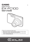
Installation Instructions ® Rheem Continuous Flow Gas Water Heaters This EZ-Link system must be installed and serviced by a qualified person. Please leave this guide with the householder. Warning: Upon completion of the installation and commissioning of the water heater, leave this guide with the householder or a responsible officer. DO NOT leave this guide inside of the cover of the water heater, as it may interfere with the safe operation of the water heater or ignite when the water heater is turned on. Notice to Victorian Customers from the Victorian Plumbing Industry Commission. This water heater must be installed by a licensed person as required by the Victorian Building Act 1993. Only a licensed person will give you a Compliance Certificate, showing that the work complies with all the relevant Standards. Only a licensed person will have insurance protecting their workmanship for 6 years. Make sure you use a licensed person to install this water heater and ask for your Compliance Certificate. RHEEM AUSTRALIA PTY LTD - ABN 21 098 823 511 1 Alan Street (PO Box 6) Rydalmere NSW 2116 Australia PATENTS This system may be protected by one or more patents or registered designs in the name of Rheem Australia Pty Ltd or Paloma Industries Ltd. ® TRADEMARKS Registered trademark of Rheem Australia Pty Ltd. ™ Trademark of Rheem Australia Pty Ltd. Note: Every care has been taken to ensure accuracy in preparation of this publication. No liability can be accepted for any consequences, which may arise as a result of its application. CONTENTS EZ-Link System ............................................................................ 3 Dual Installation ........................................................................... 6 Labels ........................................................................................... 7 Temperature Controller ............................................................... 7 Ez-Link Cable Connection .......................................................... 9 Typical Two Unit Manifold with Ez-Link Connection ............. 18 3 EZ-LINK SYSTEM EZ-Link System The EZ-Link™ system is designed to electronically control two continuous flow gas water heaters and have them operate as one. One or both water heaters may be in operation, depending upon the hot water demand. The second water heater will only operate when the hot water demand exceeds the capacity of the first water heater to supply. The EZ-Link system is suitable for installation with Rheem® indoor 862, 864, 866 and outdoor 872, 874, and 876 series and Edwards® indoor 362 and outdoor 372 series continuous flow gas water heaters. DO NOT OPERATE THIS APPLIANCE BEFORE READING THE INSTRUCTION BOOKLET. DO NOT PLACE ARTICLES ON OR AGAINST THIS APPLIANCE. DO NOT STORE CHEMICALS OR FLAMMABLE MATERIALS, OR SPRAY AEROSOLS NEAR THIS APPLIANCE. DO NOT OPERATE WITH PANELS, COVERS OR GUARDS REMOVED FROM THIS APPLIANCE. DO NOT ENCLOSE THIS APPLANCE. Ez-Link cable x 1 CERTIFIED FOR OUTDOOR INSTALLATION ONLY To operate the water heater Open the inlet water and gas valves fully Plug appliance into mains power outlet and switch on Turn on remote temperature controller(s) if fitted Open a hot tap - the heater will operate automatically To shut down the water heater Close the inlet water and gas valves fully Turn off remote temperature controller(s) if fitted If power will be disconnected, refer to the owners guide regarding draining the appliance to avoid damage due to freezing cable clamps x2 N199 AS 3498 WMKA21434 121109 AD screws x 2 warning label x 1 (121109) AGA label x 1 (121901) Warning Label x 1 (121109) Ez-Link Cable x 1 Kit – PN 290141 x 1 (121901) AGA Label Cable Clamp Ez-Link x2 + Installation Instruction x 1 (122139) Screw x2 EZ-LINK KIT (290141) 4 EZ-LINK SYSTEM Notes: Only two continuous flow gas water heaters can be installed with an Ez-Link system. The Ez-Link system will vary the start up sequence of the two water heaters. The two continuous flow water heaters must be of the same model. The performance of two different model water heaters manifolded together cannot be guaranteed. A temperature controller is required to be installed with the EZ-Link system, except for Rheem 612 to 627 and E16 models or Edwards 627 model water heaters. The controller can be either a standard or Deluxe controller. If a temperature controller is not installed, on other than a Rheem 612 to 627 or E16 models or an Edwards 627 model, neither water heater will operate. A temperature controller(s) may be installed with the EZ-Link system on a Rheem 612 to 627 or E16 model or Edwards 627 model dual installation. The controller can be either a standard or Deluxe controller. If the Ez-Link system is used with a model water heater with a preset outlet temperature greater than 60°C, the maximum outlet temperature of the water heater will be limited by the maximum temperature setting of the temperature controller, if one is installed. Two Rheem 612 to 627 or E16 models or two Edwards 627 model water heaters manifolded together with an Ez-Link system installed can be used as an in-series gas booster system to a solar water heater installation so long as a temperature controller is not installed. Warning: Two continuous flow water heaters manifolded together with an Ez-Link system installed cannot be used as an in-series gas booster system to a solar water heater installation if a temperature controller is installed. Temperature controllers must not be fitted to a water heater as part of a solar water heater system because water at a temperature much higher than the controller setting can be delivered. 5 EZ-LINK SYSTEM Dual Installation The two continuous flow water heaters can be installed side by side with minimal clearance between them. The AGA has approved the installation of two water heaters with an exemption from the 300 mm minimum clearance requirements between flue terminals, as stated in AS/NZS 5601, clause 5.13.6.5 and AS/NZS 5601.1, clause 6.9.3. Install two continuous flow water heaters of the same model in a parallel plumbing arrangement. It is good practice, but not essential, to install the two water heaters in an Equa-Flow® plumbing arrangement. The installation must be in accordance with the Owner‟s Guide and Installation Instructions supplied with the water heater. 1. The pipe work must be sized to meet the requirements of both AS/NZS 3500.4 and the application. It is recommended to use minimum DN25 pipe for the cold water line, cold and hot headers and hot water line and DN20 for the cold and hot water branch lines of each water heater. 2. A full flow gate valve or ball valve must be installed on the cold water line to the system. A non return valve or stop tap must not be installed. 3. A full flow gate valve or ball valve (not a stop tap) should be installed on both the cold water branch and hot water branch of each water heater. 4. An isolation valve must be installed on the gas branch of each water heater. 5. Non return valves or pressure limiting valves must not be installed on the branch lines to the water heaters. 6. All fittings, valves and branch lines should be matched sets to each of the water heaters. 7. Sufficient space must be left to enable access, servicing or removal of either water heater. Refer to the „Typical Two Unit Manifold with Ez-Link Connection‟ diagrams for the: 874, 876 series M16, 018, 020 models on page 18, or 874, 876 series 612, E16, 618, 620 models on page 18, or 372, 872, 874, 876 series 024, 027 models on page 19, or 372, 872, 874, 876 series 627 models on page 19, or 362, 862, 864, 866 series 027 models on page 20, or 362, 862, 864, 866 series 627 models on page 21. 6 EZ-LINK SYSTEM Labels A warning label (121109) and an AGA approval label (121901) are supplied in the Ez-Link kit. Where the two water heaters are installed close together and the warning label and AGA approval label on the inside face of the right hand water heater cannot be read, it is necessary to adhere the two labels supplied to the right-hand face of the water heater. 1. Place the warning label below the rating label. 2. Place the AGA approval label beside the barcode label. DO NOT OPERATE THIS APPLIANCE BEFORE READING THE INSTRUCTION BOOKLET. DO NOT PLACE ARTICLES ON OR AGAINST THIS APPLIANCE. DO NOT STORE CHEMICALS OR FLAMMABLE MATERIALS, OR SPRAY AEROSOLS NEAR THIS APPLIANCE. DO NOT OPERATE WITH PANELS, COVERS OR GUARDS REMOVED FROM THIS APPLIANCE. DO NOT ENCLOSE THIS APPLANCE. CERTIFIED FOR OUTDOOR INSTALLATION ONLY Refer to the „Label Positioning‟ diagram on page 7 for the position of the two labels to be adhered to the water heater. A second rating label is attached to the inside of the front cover. This can be referenced to determine details of the left hand water heater. To operate the water heater Open the inlet water and gas valves fully Plug appliance into mains power outlet and switch on Turn on remote temperature controller(s) if fitted Open a hot tap - the heater will operate automatically To shut down the water heater Close the inlet water and gas valves fully Turn off remote temperature controller(s) if fitted If power will be disconnected, refer to the owners guide regarding draining the appliance to avoid damage due to freezing N199 AS 3498 WMKA21434 121109 AD Label Positioning Temperature Controller A temperature controller is required to be installed with the EZ-Link system except for Rheem 612 to 627 or E16 model or Edwards 627 model water heaters. The controller can be either a standard or Deluxe controller. If a temperature controller is not installed, on other than a Rheem 612 to 627 or E16 model or Edwards 627 model, neither water heater will operate. Rheem 612 to 627 or E16 model or Edwards 627 model water heaters do not require a temperature controller to be installed as part of an Ez-link system installation Connect a temperature controller to one only of the two water heaters. Up to three temperature controllers of the same family can be installed to this water heater. Refer to “Installation – Controllers” in the Owner‟s Guide and Installation Instructions supplied with the water heater, for the rules applying to the installation of temperature controllers and for details on connecting a controller to the water heater. The water heater connected with the temperature controller(s) will become the “master” water heater. The installed temperature controller(s) will control the temperature and functionality of both water heaters. The maximum outlet temperature of the water heaters will be limited by the maximum temperature setting of the temperature controller. 7 EZ-LINK SYSTEM Notes: A Kitchen controller only should be installed on other than a Rheem 612 to 627 or E16 model or Edwards 627 model if two continuous flow gas water heaters have been Ez-Linked together and they are part of a circulated hot water flow and return system in a building. The Kitchen controller should be left set at 60°C and left on during the periods the circulator may operate. Water should not be circulated from a water heater with a temperature setting of less than 60°C. A temperature controller should not be installed if two Rheem 612 to 627 or E16 models or two Edwards 627 model water heaters have been Ez-Linked together and they are part of a circulated hot water flow and return system in a building. The preset outlet temperature setting of the water heaters must be set to at least 60°C if installed as part of a circulated hot water flow and return system in a building. Water should not be circulated from a water heater with a temperature setting of less than 60°C. Refer to the Owner‟s Guide and Installation Instructions supplied with the water heater for further information on installing a water heater as part of a circulated hot water flow and return system in a building. Warning: Two continuous flow water heaters manifolded together with an Ez-Link system installed cannot be used as an inline gas booster system to a solar water heater installation if a temperature controller is installed. Temperature controllers must not be fitted to a water heater as part of a solar water heater system because water at a temperature much higher than the controller setting can be delivered. 8 EZ-LINK SYSTEM Ez-Link Cable Connection The references in steps 5 to 8 are to the: „Control Board M16, 018, 020 models with Ez-Link Connection‟ diagram on page 14, and „Control Board 612, E16, 618, 620 models with Ez-Link Connection‟ diagram on page 15, and „Control Board 024, 027 models with Ez-Link Connection‟ diagram on page 16, and „Control Board 627 models with Ez-Link Connection‟ diagram on page 17. To connect the Ez-Link cable to the water heaters: 1. Close any hot taps and ensure the burners on both water heaters are not operating. 2. Switch off the electrical supply at the power outlet to each water heater. 3. Remove the screws holding the front panel to the jacket on each water heater. 4. Gently disengage the front panel and pull forward to remove from each water heater. 5. Connect one end of the EZ-Link cable to the first water heater. Draw the cable through the cable grommet on the underside of the water heater. Plug the cable into the four pin connector: E16, M16, 018, 020, 612, 618, 620 models – marked “E” in the upper right-hand corner of the Control Board. Refer to the Control Board diagram for M16, 018, 020 models and the Control Board diagram for 612, E16, 618, 620 models. 024, 027, 627 models – located immediately below the MIN button, toward the upper right hand corner of the Control Board. Refer to the Control Board diagram for 024, 027 models and the Control Board diagram for 627 models. The connector will only fit one way. Press until the connector snaps into place. 9 EZ-LINK SYSTEM Secure the EZ-Link cable with the clamp and screw provided, to: E16, M16, 018, 020, 612, 618, 620 models – the bottom right of the Control Board. Refer to the Control Board diagram for M16, 018, 020 models and the Control Board diagram for 612, E16, 618, 620 models. 024, 027, 627 models – the top right of the Control Board. Refer to the Control Board diagram for 024, 027 models and the Control Board diagram for 627 models. 6. All Models – With or Without a Controller Connected: Switch DIP SWITCH 4 to the on (up) position on the first water heater. Note: This dip switch is on the DIP 1 set of dip switches on the 024, 027 and 627 models. Note: If a controller is connected to one of the water heaters, then this is the „first‟ water heater. Refer to the: Control Board diagram for M16, 018, 020 models, or Control Board diagram for 612, E16, 618, 620 models, or Control Board diagram for 024, 027 models, or Control Board diagram for 627 models. 612, E16, 618, 620 Models – Without a Controller Connected: If a temperature controller is not installed on the 612, E16, 618, 620 models, then also switch DIP SWITCH 3 to the on (up) position on the first water heater. 627 Models – Without a Controller Connected: If a temperature controller is not installed on the 627 models, then also switch DIP SWITCH 1 of the DIP 2 set of dip switches to the on (up) position on the first water heater. 10 EZ-LINK SYSTEM 7. Connect the other end of the EZ-Link cable to the second water heater. Draw the cable through the cable grommet on the underside of the water heater. Plug the cable into the four pin connector: E16, M16, 018, 020, 612, 618, 620 models – marked “E” in the upper right-hand corner of the Control Board. Refer to the Control Board diagram for M16, 018, 020 models and the Control Board diagram for 612, E16, 618, 620 models. 024, 027, 627 models – located immediately below the MIN button, toward the upper right hand corner of the Control Board. Refer to the Control Board diagram for 024, 027 models and the Control Board diagram for 627 models. The connector will only fit one way. Press until the connector snaps into place. Secure the EZ-Link cable with the clamp and screw provided, to: E16, M16, 018, 020, 612, 618, 620 models – the bottom right of the Control Board. Refer to the Control Board diagram for M16, 018, 020 models and the Control Board diagram for 612, E16, 618, 620 models. 024, 027, 627 models – the top right of the Control Board. Refer to the Control Board diagram for 024, 027 models and the Control Board diagram for 627 models. 8. All Models – With or Without a Controller Connected: Switch DIP SWITCH 4 to the on (up) position on the second water heater. Refer to the: Control Board diagram for M16, 018, 020 models, or Control Board diagram for 612, E16, 618, 620 models, or Control Board diagram for 024, 027 models, or Control Board diagram for 627 models. Note: This dip switch is on the DIP 1 set of dip switches on the 024, 027, and 627 models. 11 1 2 3 4 11 22 33 44 DIP1 ON Water Heater no.2 No4Temperature Controller(s) 1 2 3 4 ON SK6668-46 REV_AD 2/12 Water Heater no.2 OFF Water Heater no.1 4 3 1 2 3 4 DIP2 ON OFF 1 2 3 4 ON ON DIP SWITCHES - EZ LINK INSTALLATION FLOW WATER HEATER 4 3CONTINUOUS 2 86,87 SERIES, 627 MODELS1 2 4 3 1 2 ON DIP1 1 2 3 4 OFF ON DIP2 OFF ON 3 1 2 ON ON OFF Water Heater no.1 ON OFF ON ON dip switch settings E16, M16, 018, 020, 612, 618, 620 models with controller connected 3 4 1 2 3 4 1 2 a temperature ON 4 3 2 3 4 1 ON 1 2 1 DIP2 Water Heater no.2 Water Heater no.2 Temperature Controller(s) Connected Temperature Controller(s) Connected OFF DIP1 DIP1 DIP2 Water Heater no.1 Water Heater no.1 (with controller(s) connected) (with controller(s) connected) ON OFF ON ON OFF ON OFF 2 3 4 11 22 3 33 4 44 1 2 1 OFF 333 444 1 22 33 44 2 22 ON ON ON DIP1 DIP1 DIP2 4 3 2 11 4 1 2 3 4 ON ON ON 1 3 2 1 Temperature Controller(s) Connected OF Water Heater no.2 ON OFF ON OFF ON OFF DIP1 DIP1 DIP2 EZ-LINK SYSTEM 4 3 2 1 OF Water Heater no.1 (with controller(s) connected) No Temperature Controller(s) 4 switch settings 3 dip 1 2 3 4 E16, 612, 618, 620 models 4 3 1 2 3 4 1 2DIP SWITCHES - EZ LINK INSTALLATION without a temperature controller Water Heater no.1 Water Heater no.2 CONTINUOUS FLOW WATER HEATER 2 1 DIP1 4 3 2 1 1 2 3 4 ON ON OFF 4 3 2 DIP2 ON ON 1 SK6668-46 REV_AD 2/12 1 2 3 4 OFF DIP2 1 2 3 4 4 3 2 1 OFF 4 3 2 1 ON ON DIP SWITCHES - EZ LINK INSTALLATION ON CONTINUOUS FLOW WATER HEATER 86,87 SERIES, 627 MODELS ON OFF DIP1 87 SERIES, 612 - 620 MODELS No Temperature Controller(s) 1 2 3 4 Water Heater no.1 (with controller(s) connected) Water Heater no.2 2 3 4 12 1 2 3 ON 4 OFF 1 DIP1 ON dip switch settings 024, 027, 627 models with a temperature controller connected ON ON OFF DIP1 Temperature Controller(s) Connected Water Heater no.1 (with controller(s) connected) Water Heater no.2 EZ-LINK SYSTEM 4 1 2 3 4 1 3 4 ON 4 ON DIP2 ON 2 3 1 2 3 4 OFF DIP2 ON 2 1 OFF 3 ON 2 ON 1 2 3 4 OFF 1 DIP1 ON ON OFF DIP1 Temperature Controller(s) Connected 1 2 3 4 1 2 3 4 Water Heater no.1 Water Heater no.2 No Temperature Controller(s) dip switch settings 627 models DIP SWITCHES - EZ LINK INSTALLATION without a temperature controller CONTINUOUS FLOW WATER HEATER 86,87 SERIES, 627 MODELS 9. Refit the front panel and screws to each water heater. SK6668-46 REV_AD 2/12 10. Check the main gas isolation valve and the isolation valves at the gas inlet to each water heater are fully open. 11. Switch on the electrical supply at the power outlet to the water heater. 12. Turn on the controller by pressing the on / off button, if one is installed. 13. Open a hot tap. The first water heater and depending upon the flow from the hot tap, the second water heater will operate automatically. 14. Increase the hot water flow by turning on an additional hot tap(s). Check to ensure the flow from each connected hot tap is sufficient to operate both water heaters. The minimum operating flow rate for each E16, M16, 018, 020, 612, 618 and 620 model water heater is 2.5 litres per minute and for each 024, 027 and 627 model water heater is 2.0 litres per minute. 15. Turn off the hot taps. Refer to the “Commissioning” section in the Owner‟s Guide and Installation Instructions supplied with the water heater for details on completing the installation. 13 EZ-LINK SYSTEM Controller Cable (one water heater only) SW2 1 2 3 4 1 2 3 4 E REMOTE CONTROLLER TERMINAL ON ON OFF DIP1 SW1 ON ON 1 2 3 4 1 2 3 4 E Secure cable with cable clamp & screw OFF DIP1 Ez-Link Cable Both Water Heaters Dip Switch 4 in the on (up) position Control Board M16, 018, 020 models with Ez-Link Connection Ez-Link Cable Connection 874, 876 SERIES 012 - 020 MODELS 14 EZ-LINK SYSTEM Optional Controller Cables (first water heater only) SW2 2 3 4 1 2 3 4 E Ez-Link Cable OFF DIP1 ON 1 REMOTE CONTROLLER TERMINAL ON SW1 DIP SWITCH SETTINGS 1st WATER HEATER ON 1 ON 2 3 4 1 2 3 4 WITH CONTROLLER Dip Switch 4 'on' 1 2 3 E 4 1 2 3 4 WITHOUT CONTROLLER Dip Switches 3 & 4 'on' 2nd WATER HEATER Plug EZ-link cable into connector 'E' ON 1 2 ON 3 4 1 2 3 4 WITH CONTROLLER Dip Switch 4 'on' 1 2 3 Secure cable with cable clamp & screw 4 1 2 3 4 EZ-link cable drawn through cable grommet on underside of each water heater WITHOUT CONTROLLER Dip Switch 4 'on' Ez-link Cable Connection 874, 876 series 612-620 models Control Board 612, E16, 618, 620 models with Ez-Link Connection SK7255 06/12 REV AD 15 EZ-LINK SYSTEM SECURE CABLE WITH CABLE CLAMP AND SCREW DIP1 ON 1 2 3 4 1 2 3 4 OFF ON DIP SWITCH 4 OF DIP1 SET OF DIP SWITCHES IN THE ON (UP) POSITION EZ-LINK CABLE PLUG IN EZY-LINK CABLE INTO CONNECTOR EZ-LINK CABLE CONNECTION CONTINUOUS FLOW WATER HEATER 86,87 SERIES, 022,024,027 MODELS Control Board 024, 027 models with Ez-Link Connection 16 EZ-LINK SYSTEM (WITH OR WITHOUT CONTROLLER) BOTH WATER HEATERS DIP SWITCH 4 OF DIP1 SET OF DIP SWITCHES IN THE ON (UP) POSITION SECURE CABLE WITH CABLE CLAMP AND SCREW ON EZ-LINK CABLE 3 4 1 2 3 4 (WITHOUT CONTROLLER) FIRST WATER HEATER ONLY DIP SWITCH 1 OF DIP 2 SET OF DIP SWITCHES IN THE ON (UP) POSITION ON 2 DIP2 ON 2 3 4 2 3 4 ON 1 1 1 2 3 4 1 2 3 4 OFF DIP2 ON PLUG IN EZ-LINK CABLE INTO CONNECTOR OFF 1 OFF DIP1 ON (WITHOUT CONTROLLER) SECOND WATER HEATER ONLY (WITH CONTROLLER) BOTH WATER HEATERS ALL DIP SWITCHES IN THE OFF (DOWN) POSITION ControlCABLE Board 627 models with EZ-LINK CONNECTION CONTINUOUS FLOW WATER HEATER 86,87 SERIES, 627 MODELS Ez-Link Connection SK6668-47 REV_AD 2/12 17 EZ-LINK SYSTEM Typical Two Unit Manifold with Ez-Link Connection MANIFOLD INSTALLATION - EZ LINK CONNECTION TWO CONTINUOUS FLOW WATER HEATERS - 874, 876 SERIES 012 - 020 & 612 - 620 MODE eaves, balconies & other projections no minimum distance requirement 350 300 MIN to return wall & openings into building 300 MIN Temperature Controller(s) (installed indoors) (Optional 612 - 620 Models) in use priority °C x10 check hot water temperature before use water volume on off Weatherproof GPO x 2 K Controller Cable Ez-Link Cable COLD WATER SUPPLY HOT WATER TO OUTLETS GAS SUPPLY PIPE SIZES: Manifold DN25 Branches DN20 NOTE: PRESSURE LIMITING DEVICE (PLV) REQUIRED TO TLD IF PLV INSTALLED AT WATER HEATER NOTE: NON RETURN VALVES (NRV) REQUIRED ON COLD AND HOT SUPPLY LINES TO A TEMPERATURE LIMITING DEVICE (TLD) IF NOT INCORPORATED IN TLD. TEMPERATURE LIMITING DEVICE IF REQUIRED SUITABLE FOR MAXIMUM FLOW. COLD WATER TEMPERED WATER TO OUTLETS SUPPLY LEGEND ISOLATION VALVE (FULL FLOW) PRESSURE LIMITING VALVE NON RETURN VALVE TEMPERING VALVE Typical Two Unit Manifold with Ez-Link Connection Outdoor 874, 876 Series – M16, 018, 020, 612, E16, 618, 620 Models Refer to the Owner‟s Guide and Installation Instructions supplied with the water heater for additional information on the installation of the water heaters. 18 EZ-LINK SYSTEM MANIFOLD INSTALLATION - EZ LINK CONNECTION TWO CONTINUOUS FLOW WATER HEATERS - 872,874,876 SERIES 027 & 627 MODELS eaves, balconies & other projections no minimum distance requirement 350 300 MIN to return wall 300 Min. openings into building 500 Min. Temperature Controller(s) (installed indoors) (optional 627 models) in use priority °C x10 check hot water temperature before use water volume on off Weatherproof GPO x 2 K Controller Cable Ez-Link Cable COLD WATER SUPPLY HOT WATER TO OUTLETS GAS SUPPLY PIPE SIZES: Manifold DN25 Branches DN20 NOTE: PRESSURE LIMITING DEVICE (PLV) REQUIRED TO TLD IF PLV INSTALLED AT WATER HEATER NOTE: NON RETURN VALVES (NRV) REQUIRED ON COLD AND HOT SUPPLY LINES TO A TEMPERATURE LIMITING DEVICE (TLD) IF NOT INCORPORATED IN TLD. TEMPERATURE LIMITING DEVICE IF REQUIRED SUITABLE FOR MAXIMUM FLOW. COLD WATER TEMPERED WATER TO OUTLETS SUPPLY LEGEND ISOLATION VALVE (FULL FLOW) PRESSURE LIMITING VALVE NON RETURN VALVE TEMPERING VALVE Typical Two Unit Manifold with Ez-Link Connection Outdoor 372, 872, 874, 876 Series – 024, 027, 627 Models Refer to the Owner‟s Guide and Installation Instructions supplied with the water heater for additional information on the installation of the water heaters. 19 EZ-LINK SYSTEM MANIFOLD INSTALLATION - EZ LINK CONNECTION TWO CONTINUOUS FLOW WATER HEATERS - 862,864,866 SERIES 027 MODELS no minimum distance requirement 350 Temperature Controller (installed indoors) in use priority °C x10 check hot water temperature before use water volume on off K GPO x 2 Controller Cable Ez-Link Cable COLD WATER SUPPLY HOT WATER TO OUTLETS GAS SUPPLY PIPE SIZES: Manifold DN25 Branches DN20 NOTE: PRESSURE LIMITING DEVICE (PLV) REQUIRED TO TLD IF PLV INSTALLED AT WATER HEATER NOTE: NON RETURN VALVES (NRV) REQUIRED ON COLD AND HOT SUPPLY LINES TO A TEMPERATURE LIMITING DEVICE (TLD) IF NOT INCORPORATED IN TLD. TEMPERATURE LIMITING DEVICE IF REQUIRED SUITABLE FOR MAXIMUM FLOW. COLD WATER TEMPERED WATER TO OUTLETS SUPPLY LEGEND ISOLATION VALVE (FULL FLOW) PRESSURE LIMITING VALVE NON RETURN VALVE TEMPERING VALVE Typical Two Unit Manifold with Ez-Link Connection Indoor 362, 862, 864, 866 Series – 027 Models Refer to the Owner‟s Guide and Installation Instructions supplied with the water heater for additional information on the installation of the water heaters. 20 EZ-LINK SYSTEM MANIFOLD INSTALLATION - EZ LINK CONNECTION TWO CONTINUOUS FLOW WATER HEATERS - 862,864,866 SERIES 627 MODELS no minimum distance requirement 350 Temperature Controller (installed indoors) (optional-627 models) in use priority °C x10 check hot water temperature before use water volume on off K GPO x 2 Controller Cable Ez-Link Cable COLD WATER SUPPLY HOT WATER TO OUTLETS GAS SUPPLY PIPE SIZES: Manifold DN25 Branches DN20 NOTE: PRESSURE LIMITING DEVICE (PLV) REQUIRED TO TLD IF PLV INSTALLED AT WATER HEATER NOTE: NON RETURN VALVES (NRV) REQUIRED ON COLD AND HOT SUPPLY LINES TO A TEMPERATURE LIMITING DEVICE (TLD) IF NOT INCORPORATED IN TLD. TEMPERATURE LIMITING DEVICE IF REQUIRED SUITABLE FOR MAXIMUM FLOW. COLD WATER TEMPERED WATER TO OUTLETS SUPPLY LEGEND ISOLATION VALVE (FULL FLOW) PRESSURE LIMITING VALVE NON RETURN VALVE TEMPERING VALVE Typical Two Unit Manifold with Ez-Link Connection Indoor 362, 862, 864, 866 Series – 627 Models Refer to the Owner‟s Guide and Installation Instructions supplied with the water heater for additional information on the installation of the water heaters. 21 This page is intentionally blank. 22 This page is intentionally blank. 23 Revision Date: 2012 July 122139C 24