1
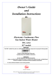
EZ-LINK SYSTEM
Typical Two Unit Manifold with Ez-Link Connection
MANIFOLD INSTALLATION - EZ LINK CONNECTION
TWO CONTINUOUS FLOW WATER HEATERS - 874, 876 SERIES 012 - 020 & 612 - 620 MODE
eaves, balconies
& other projections
no minimum
distance
requirement
350
300
MIN
to return wall &
openings into building
300 MIN
Temperature
Controller(s)
(installed indoors)
(Optional
612 - 620 Models)
in use
priority
°C
x10
check
hot water
temperature
before use
water
volume
on
off
Weatherproof
GPO x 2
K
Controller
Cable
Ez-Link
Cable
COLD WATER SUPPLY
HOT WATER
TO OUTLETS
GAS SUPPLY
PIPE SIZES:
Manifold DN25
Branches DN20
NOTE:
PRESSURE
LIMITING DEVICE
(PLV)
REQUIRED TO
TLD IF PLV
INSTALLED AT
WATER HEATER
NOTE: NON RETURN
VALVES (NRV)
REQUIRED ON COLD AND
HOT SUPPLY LINES TO A
TEMPERATURE LIMITING
DEVICE (TLD) IF NOT
INCORPORATED IN TLD.
TEMPERATURE LIMITING DEVICE
IF REQUIRED
SUITABLE FOR MAXIMUM FLOW.
COLD WATER
TEMPERED
WATER
TO
OUTLETS
SUPPLY
LEGEND
ISOLATION VALVE (FULL FLOW)
PRESSURE LIMITING VALVE
NON RETURN VALVE
TEMPERING
VALVE
Typical Two Unit Manifold with Ez-Link Connection
Outdoor 874, 876 Series – M16, 018, 020, 612, E16, 618, 620 Models
Refer to the Owner‟s Guide and Installation Instructions supplied with the water
heater for additional information on the installation of the water heaters.
18