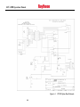
1
ACU-1000 Operations Manual
2.10 Local Radio Interface & Optimization
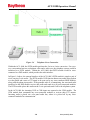
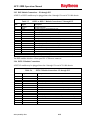
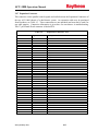
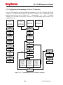
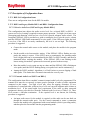
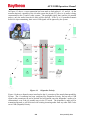
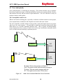
There are three major steps to interfacing radios and other four-wire devices to a DSP module:
•
Connect the communications devices to ACU-1000 rear panel D15 connectors using
properly designed interface cables (either purchased from Raytheon JPS or
designed/built by the customer).
•
Optimize each individual interface/ACU extension.
•
Optimize the operation of each extension when cross-connected with the other
extensions in the system.
This section explains how best to perform these steps. Acceptable communications links are
possible without following all of the steps described, but following the procedures outlined will
provide seamless communications in a wide variety of difficult communications environments.
These procedures may appear more complicated than those required for less sophisticated
interoperability devices. This is largely because this other equipment does not provide many of
the features that the ACU-1000 employs to resolve complex interoperability problems.
Raytheon JPS has simplified the interface process by:
•
Proper design of interface cables
•
Coordination of the use of these cables with the ACU Controller software
•
Applications Notes describing
communications devices
•
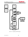
Use of templates to load settings that have been optimized for each individual device
•
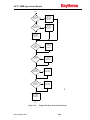
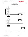
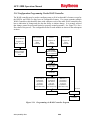
Flow charts to guide the installer through the final optimization steps
the
peculiarities
associated
with
individual
All of these are explained in the following sub-sections, using the Universal Unterminated
Cable Application Notes as a guideline.
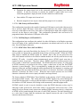
2.10.1 Interface Cables for Radios and Other Communications Devices
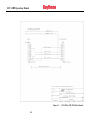
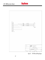
The systems engineers at Raytheon JPS Communications have created interface cables and
accompanying Application Notes for a large number of radios and other communications
devices. Many of these Application Notes are included on the Resource CD that’s included
with the ACU-1000.
2-18
Interoperability Now