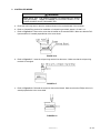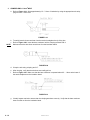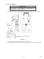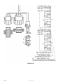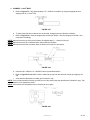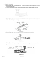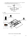
1
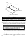
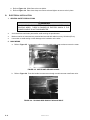
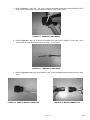
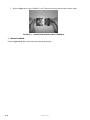
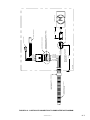
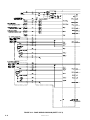
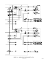
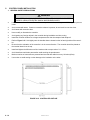
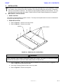
PRINT
TABLE OF CONTENTS
II.
INSTALLATION
T
he RICON PF7000 Series Express Ramp has been engineered and designed for custom installations. Installation consists of the mounting of the ramp, installation of the electrical supply and control wiring, controller adjustment, and installation verification. This chapter provides installation guidelines and instructions. If a question arises that is not covered in this chapter, contact the Ricon Product Support Department for assistance.
A.
MECHANICAL INSTALLATION
1. RAMP LOCATION
The location of ramp depends on its path of motion. The ramp must be positioned so it can move unobstructed
through its required range of travel.
2. RAMP INSTALLATION
a. Refer to Figure 2-1. Remove cover strip screws.
b. Refer to Figure 2-1. Remove cover strips.
SCREWS
COVER STRIPS
FIGURE 2-1: REMOVAL OF COVER STRIPS
WARNING!
TAKE EXTREME CARE WHEN POSITIONING RAMP INTO TRAIN. BE SURE TO FOLLOW PROPER
OPERATION AND SAFETY INSTRUCTIONS WHEN USING LIFTING DEVICE.
c.
Refer to Figure 2-2. Install eye bolts (provided in kit #39022) in the locations shown in Figure 2-2. Use
crane or lifting hoist to place ramp into train.
d. Once ramp is properly placed into train, remove eye bolts.
e. Refer to Figure 2-2. Remove access panel.
32DPF702.A
2-1
EYE BOLTS
ACCESS PANEL
EYE BOLTS
FIGURE 2-2: EYE BOLT LOCATIONS
f.
Refer to Figure 2-3. Rotate timing belt approximately 25-30 times in the direction shown in Figure 2-3
until the tip of the ramp appears approximately 50mm out of the enclosure.
WARNING!
VERIFY THAT THE HINGED FLOOR IS PROPERLY LOCKED IN A RAISED POSITION BEFORE
ATTEMPTING TO INSTALL RAMP. THIS WILL HELP PREVENT INJURY WHILE INSTALLING THE RAMP.
g. Refer to Figure 2-3. Use rod found under hinged floor to support and lock hinged floor in a raised position.
NOTE: Mechanical support of the ramp must be made using six provided attachment points located on three sides of
the ramp. Each attachment point uses two bolts, for a total of 12 bolts, that must be a minimum of 10 mm diameter. Please use mounting hardware provided with the ramp in kit #39021.Please use mounting hardware
provided with the ramp in kit #39021.
WARNING!
DURING RAMP INSTALLATION, BE SURE THERE ARE NO GAPS BETWEEN THE TRAIN’S
RAMP FRAME BRACKET AND THE BOTTOM OF THE RAMP ENCLOSURE. IF GAPS EXIST, THE
RAMP WILL DEFORM WHEN MOUNTING BOLTS ARE TIGHTENED. FLEXURE EXCEEDING +/1/25” (1mm) MAY CAUSE UNINTENDED OVER CURRENT CONDITIONS THAT WILL RESULT IN
RAMP MALFUNCTION. RAMP WILL NOT DEPLOY OR STOW AUTOMATICALLY.
h. Check for gaps between the train’s ramp frame bracket and the bottom of the ramp enclosure. Should
there be any gaps, insert spacers as needed (i.e. flat washers, etc.) to assure that the ramp enclosure
does not deform when bolts are tightened.
2-2
i.
Refer to Figure 2-3. Install 4 flat washers, spring washers and mounting bolts at rear end, two on each
side.
j.
Refer to Figure 2-3. Install 4 flat washers, spring washers and mounting bolts at mid section, two on each
side.
k.
Refer to Figure 2-3. Install 4 flat washers, spring washers and mounting bolts at front, two on each side.
32DPF702.A
REAR END
MOUNTING HARDWARE
MID-SECTION
MOUNTING HARDWARE
FRONT MOUNTING
HARDWARE
ROD
RAISED
HINGED
FLOOR
FIGURE 2-3: INSTALLING MOUNTING FASTENERS
l.
Tighten mounting bolts in an alternating pattern in small increments, stepping up to the maximum value of
27 to 33Nm manually using a manual torque wrench. Do not tighten each bolt all at once. A pneumatic or
any automatic device is not recommended.
m. Perform electrical installation before continuing with the following step. For electrical installation, please
refer to the Electrical Installation section of this chapter.
n. Disengage rod under hinged floor and secure underneath with clip. Close hinged floor.
o. Rotate timing belt in opposite direction until the ramp is fully stowed.
p. Install access panel.
q. Install cover strips and hardware.
3. 3. FLUTTER DRAIN VALVE INSTALLATION
The purpose of the flutter valve is to allow fluid to drain out of enclosure, while keeping debris from entering. Flutter valve and hose clamp are provided with ramp in kit #39023.
FLUTTER VALVE
HOSE CLAMP
FIGURE 2-4: FLUTTER VALVE INSTALLATION
32DPF702.A
2-3
a. Refer to Figure 2-4. Slide flutter valve onto holder.
b. Refer to Figure 2-4. Place hose clamp over flutter valve and tighten to secure valve in place.
B.
ELECTRICAL INSTALLATION
1. GENERAL SAFETY PRECAUTIONS
WARNING!
MAKE SURE THAT THE POWER SOURCE IS DISCONNECTED WHEN
ROUTING WIRES. THERE IS DANGER OF ELECTRIC SHOCK IF THE
POWER SOURCE IS NOT DISCONNECTED.
♦
Avoid interference with train parts and/or avoid touching the protuberance.
♦
Make sure wires or harnesses are protected and secured with cable ties every 18 inches (45 cm).
♦
Use caution to avoid tearing or other damage to the insulation on the wires.
2. MAIN WIRING
a. Refer to Figure 2-5. Locate motor cable and sensor cable inside ramp enclosure next to the motor.
FIGURE 2-5: MOTOR AND SENSOR CABLES
b. Refer to Figure 2-6. Run wire bundle into motor area through conduit connector near flutter valve.
FIGURE 2-6: PASSING WIRE BUNDLE THROUGH HOLE
2-4
32DPF702.A
c.
Refer to Figure 2-7. Strip .350 - .370” (8.90 - 9.40mm) of insulation from end of the two 8 AWG (6 mm2)
wires. Use a crimping tool to crimp terminal onto both 8 AWG (6 mm2) wires.
FIGURE 2-7: CRIMPING 8 AWG WIRES
d. Refer to Figure 2-8. Strip 1/4” (6.35 mm) of insulation from end of each 14 AWG (1.5 mm2) wire. Use a
crimping tool, to crimp terminal onto all six 14 AWG (1.5 mm2) wires.
FIGURE 2-8: CRIMPING 14 AWG WIRES
e. Refer to Figures 2-9 and 2-10. Insert 8 AWG (6 mm2) wires into Molex connector and connect to motor
cable.
FIGURE 2-9: WIRE TO MOLEX CONNECTOR
FIGURE 2-10: MOTOR CONNECTION
32DPF702.A
2-5
f.
Refer to Figure 2-11. Insert 14 AWG (1.5 mm2) wires into connector and connect to sensor cable.
FIGURE 2-11: CONNECTING SENSOR CABLE TERMINALS
3. WIRING DIAGRAMS
Refer to Figures 2-12, 2-13, and 2-14 on the following three pages.
2-6
32DPF702.A
FIGURE 2-12: CONTROLLER CONNECTION TO RAMP INTERFACE DIAGRAM
32DPF702.A
2-7
CABLE AND CONDUIT (PMA N o. VOHG-17)
PROVIDED BY CAR BUILDER
CONDUIT CONNEC TOR (PMA N o. BVND-M257G T)
SUPPLIED WITH RAMP
ENCLOSURE
BLU
RED
BRN
BLK
RRSS2 / LRSS2
RRSV1 / LRSV1
BLU
RRSV2 / LRSV2
YEL
RRG2 / LRG2
RRM0 / LRM0
RRMI / LRMI
6.0 [152]
CONNEC TOR (MOLEX N o. 19432-001) AND
TERMINAL PINS (MOLEX N o. 19434-001)
PROVIDED BY RICON
RRSS1 / LRSS1
RRG1 / LRG1
WHT
BLK
CONNECTION MADE BY CAR BUILDER
4.0 [102]
CONNEC TOR (WE ATHER-PACK, PACKARD N o. 12015799),
TERMINAL PINS (WE ATHER-PACK, PACKARD N o. 12124580)
AND SEALS PROVIDED BY RICON
CONNECTION MADE BY CAR BUILDER
PROXIMITY SENSOR (LS1)
LIMIT SWI TCH (LS2)
M
DRIVE M OTOR (DM)
FIGURE 2-13: RAMP WIRING DIAGRAM (SHEET 1 OF 2)
2-8
32DPF702.A
FIGURE 2-14: RAMP WIRING DIAGRAM (SHEET 2 OF 2)
32DPF702.A
2-9
C.
CONTROL PANEL INSTALLATION
1. GENERAL SAFETY PRECAUTIONS
WARNING!
DO NOT TOUCH OR GO NEAR THE CONTROLLER WHILE IT IS POWERED.
THERE IS A RISK OF ELECTRIC SHOCK AND/OR BURN INJURY.
♦
Handle the controller with care. Do not throw or drop the controller, as doing so could damage components
inside.
♦
Avoid contact with water. If water or excessive moisture is present, do not install or route the wires.
♦
Avoid areas with excessive dust.
♦
Never modify or dismantle the controller.
♦
Avoid getting any foreign objects in the controller during installation and wire routing.
♦
Install the controller inside a low voltage compartment box that is waterproof and dustproof.
♦
Refer to Figure 2-15. Hold tightly onto the handles that are located on the left and right side of the controller.
♦
Be sure that the orientation of the controller is in the correct direction. The controller should be placed so
the terminal board is on the top.
♦
Install and tighten the M8 bolts on all six locations with a torque value of 13 ~15 Nm.
♦
Avoid interference with train parts and/or avoid touching the protuberance.
♦
Make sure wires or harnesses are protected and secured with cable ties every 18 inches (45cm).
♦
Use caution to avoid tearing or other damage to the insulation on the wires.
FIGURE 2-15: CONTROLLER OUTLINE
2 - 10
32DPF702.A
2. CONTROLLER WIRING
WARNING!
MAKE SURE THAT THE POWER SOURCE IS DISCONNECTED WHEN
ROUTING WIRES. THERE IS DANGER OF ELECTRIC SHOCK IF THE
POWER SOURCE IS NOT DISCONNECTED.
a. Route the train body wires to the wire numbers shown on the terminal board of the controller.
b. Refer to Crimped Ring sections for installation of crimped ring terminals, pages 2-12 and 2-13.
c.
Refer to Figure 2-16. Remove the screw that is located on the terminal board. Make sure that the Phillips screwdriver is inserted perpendicular to the screw head.
FIGURE 2-16
d. Refer to Figure 2-17. Insert the crimped ring terminal into the screw. Make sure that the crimped ring
terminal is not angled.
FIGURE 2-17
e. Refer to Figure 2-18. Reinstall the screw into the terminal board. Make sure that the Phillips driver is inserted perpendicular to the screw head.
FIGURE 2-18
32DPF702.A
2 - 11
3. CRIMPED RING- 1.5mm2 WIRE
a. Refer to Figure 2-19. Strip approximately 6.5 ~ 7.0mm of insulation by using the appropriate wire stripping tool for a 1.5mm2 wire.
FIGURE 2-19
b. To easily insert the bare conductor into the terminal, straighten the tip of the wire.
c.
NOTE:
Refer to Figure 2-20. Insert the bare conductor into the crimping terminal PS2-4.
Make sure that the wire does not stick out from the insulation barrel.
FIGURE 2-20
d. Crimp the wire using crimping tool H-7.
e. After crimping, verify that the wire does not readily pull out.
f.
Refer to Figure 2-21. Make sure that the bare conductor is exposed about 0.5 ∼ 1.0mm at the base of
the terminal adjacent to the insulation barrel.
FIGURE 2-21
g. Visually inspect terminal to ensure that the crimping was done correctly. Verify that the bare conductor
does not stick out from the insulation barrel.
2 - 12
32DPF702.A
4. CRIMPED RING- 6mm2 WIRE
a. Refer to Figure 2-22. Strip approximately 9.0 ~ 9.5mm of the insulation by using the appropriate wire
stripping tool for a 6mm2 wire.
FIGURE 2-22
b. To easily insert the bare conductor into the terminal, straighten the tip of the wire.
c.
NOTE:
Refer to Figure 2-23. Insert the wire into the crimping terminal PS5.5-5.
Make sure that the wire does not stick out from the insulation barrel.
FIGURE 2-23
d. Crimp the wire using crimping tool H-8.
e. After crimping, verify that the wire does not readily pull out.
f.
Refer to Figure 2-24. Make sure that the bare conductor is exposed about 0.5 ∼ 1.0mm at the base of
the terminal adjacent to the insulation barrel.
FIGURE 2-24
g. Visually inspect to ensure that the crimping was done correctly. Verify that the bare conductor does not
stick out from the insulation barrel.
32DPF702.A
2 - 13
D.
CONTROL PANEL INSTALLATION
1. GENERAL SAFETY PRECAUTIONS
WARNING!
DO NOT TOUCH THE REAR SIDE OF THE CONTROL PANEL WHILE IT IS
POWERED. THERE IS A RISK OF ELECTRIC SHOCK AND/OR BURN INJURY.
WARNING!
DO NOT INSTALL THE CONTROL PANEL IN A LOCATION THAT IS ACCESIBLE
TO THE GENERAL PUBLIC AND PASSENGERS. THE CONTROL PANEL SHOULD
BE ONLY ACCESSIBLE TO THE OPERATOR WHICH WILL PREVENT
UNINTENDED OPERATION WHICH CAN RESULT IN INJURY.
♦
Handle the control panel with care. Do not throw or drop the control panel, as doing so could damage components inside.
♦
Avoid contact with water. If water or excessive moisture is present, do not install or route the wires.
♦
Avoid areas with excessive dust.
♦
Never modify or dismantle the control panel.
♦
Avoid getting any foreign objects in the control panel during installation and wire routing.
♦
Install the control panel in a location that is out of reach from the general public and passengers and is
waterproof and dustproof. It is recommended that control panel be installed in a compartment with a key
which is only available to the operator.
♦
Install and tighten the M3 bolts on all four locations with a torque value of 0.63 Nm.
♦
Avoid interference with train parts and/or avoid touching the protuberance.
♦
Make sure wires or harnesses are protected and secured with cable ties every 18 inches (45cm).
♦
Use caution to avoid tearing or other damage to the insulation on the wires.
2 - 14
32DPF702.A
2. CONTROL PANEL WIRING
WARNING!
MAKE SURE THAT THE POWER SOURCE IS DISCONNECTED WHEN
ROUTING WIRES. THERE IS DANGER OF ELECTRIC SHOCK IF THE
POWER SOURCE IS NOT DISCONNECTED.
a. Refer to Figure 2-25. Locate motor cable and controller signal cables located behind the control panel.
3 Poles
Controller
Signal Cable
6 Poles Controller
Signal Cable
2 Poles
Motor Cable
FIGURE 2-25
b. Refer to Crimped Terminal sections for installation of crimped terminals.
c.
Refer to Figure 2-26. Connect the plugs and the caps of the connectors firmly as shown on Figure 2-26.
32DPF702.A
2 - 15
FIGURE 2-26
2 - 16
32DPF702.A
3. CRIMPED - 1.5mm2 WIRE
a. Refer to Figure 2-27. Strip approximately 4.75 ± 0.38mm of insulation by using the appropriate wire
stripping tool for a 1.5mm2 wire.
FIGURE 2-27
b. To easily insert the bare conductor into the terminal, straighten the tip of the bare conductor.
c.
Refer to Figure 2-28. Insert the stripped wire and the pin 350551-1 into the crimping tool 91500-1 and
crimp them accordingly.
NOTE: Make sure that the tip of the bare conductor is exposed about 0 ∼ 1.0mm from the pin.
NOTE: Make sure that the pin’s insulation barrel firmly holds the insulation.
NOTE: Make sure that the bare conductor does not stick out from the pin’s wire barrel.
FIGURE 2-28
d. Insert the cap 1-480701-0 or 1-480705-0 into the prescribed location.
e. Refer to Figure 2-28 and 2-29. Push the cable into the cap until the lances of the pin get caught by the
cap.
f. Verify that the cable does not readily pull out from the cap.
NOTE: If the pin was inserted incorrectly, pull the pin out of the cap by using the specified tool (1804030-1 amp). Pay
attention not to squash the lances.
NOTE: If the lances were squashed or bent, crimp the pin once again.
FIGURE 2-29
32DPF702.A
2 - 17
4. CRIMPED - 6mm2 WIRE
a. Refer to Figure 2-30. Strip approximately 9.0 ∼ 10.0mm of insulation by using the appropriate wire stripping tool for a 6mm2 wire.
b. To easily insert the bare conductor into the female terminal, straighten the tip of the bare conductor.
FIGURE 2-30
c.
Refer to Figure 2-31. Insert the female terminal 42815-0031 and the stripped wire into the crimping tool
63811-1500 and crimp them accordingly.
FIGURE 2-31
d. Refer to Figure 2-32. Insert the crimped wire into the receptacle housing 42816-0212.
FIGURE 2-32
e. Refer to Figure 2-33. Insert the crimped wire into the receptacle housing until the terminal’s latch is engaged. Remove the tab that is attached to the top of the housing.
FIGURE 2-33
2 - 18
32DPF702.A
f. Refer to Figure 2-34. Install the tab that was removed from the housing as shown in Figure 2-34.
g. Insert the tab’s retention strap into the housing retention ramp.
h. Verify that the cable does not readily pull out from the receptacle housing.
FIGURE 2-34
E.
DECALS
Refer to Figure 2-9. Verify that all decals are properly located and affixed as shown.
CORP ORATION
MAN UA L RAMP OPE RA TION
PART OF SERIAL
NUMBER DECAL
(RICON REPLACEABLE)
CORP ORATION
PART OF SERIAL
NUMBER DECAL
(RICON REPLACEABLE)
MANUAL RAMP
OPERATION DECAL
(LOCATED NEAR
RAMP) PN 36957
WHEELCHAIR
LOADING DECAL
(LOCATED NEAR
RAMP) PN 36956
POWER MOVABLE RAMP
T his produc t is cover ed by U .S. Patent No.x,xxx,xxx;
Other U .S. and foreign patents pending.
xxxxx.x
POWER MOVABLE
RAMP PATENT
NO. DECAL
PN 10580
FIGURE 2-35: DECAL LOCATIONS AND PART NUMBERS
32DPF702.A
2 - 19
This page intentionally left blank.
BACK TO TOP
2 - 20
32DPF702.A