1
Dell 2355dn
Service Manual
29 Jul 2010
Information in this document is subject to change without notice.
2010 Dell Inc. All rights reserved.
Reproduction in any manner whatsoever without the written permission of Dell Inc.is strictly forbidden.
Trademarks used in this text: Dell and the DELL logo are trademarks of Dell Inc.
Other trademarks and trade names may be used in this document to refer to the entities claiming the marks and
names of their products. Dell Inc. disclaims any proprietary interest in trademarks and trade names other than its
own.
Contents
chapter 1 Precautions
1.1
1.2
1.3
1.4
Safety Warning ……………………………………………………
Caution for safety …………………………………………………
ESD Precautions …………………………………………………
Super Capacitor or Lithium Battery Precautions ………………
1-1
1-2
1-5
1-5
chapter 2 Product spec and feature
2.1 Product Specifications ……………………………………………
2.1.1 Product Overview ………………………………………………
2.1.2 Product General Specifications ………………………………
2.2 System Outline ……………………………………………………
2.2.1 System Configurations …………………………………………
2-1
2-1
2-2
2-10
2-10
chapter 3 Disassembly and Reassembly
3.1 General Precautions on Disassembly …………………………
3.2 General Disassembly ……………………………………………
3.2.1 Cover …………………………………………………………
3.2.2 Fuser-Unit ……………………………………………………
3.2.3 Controller Board ……………………………………………
3.2.4 Scanner ASS’Y and DADF Unit ……………………………
3.2.5 OPE-Unit ……………………………………………………
3.2.6 Cover-Middle and Cover-Exit ………………………………
3.2.7 LSU-Unit ………………………………………………………
3.2.8 Drive-Unit ……………………………………………………
3.2.9 Pick_Up Roller ………………………………………………
3.2.10 SMPS ………………………………………………………
3.2.11 HVPS ………………………………………………………
3.2.12 Transfer Roller ………………………………………………
3-1
3-2
3-2
3-3
3-4
3-5
3-6
3-7
3-8
3-8
3-9
3-9
3-10
3-10
Contents
chapter 4 Alignment and Troubleshooting
4.1 Alignment and Adjustments ………………………………………
4.1.1 Paper path ……………………………………………………
4.1.2 Clearing Paper Jams ………………………………………
4.1.3 Diagnostic Mode ……………………………………………
4.1.4 Consumables and Replacement Parts ……………………
4.2 Troubleshooting……………………………………………………
4.2.1 Procedure of Checking the Symptoms ……………………
4.2.2 Abnormal Image Printing and Defective Roller……………
4.2.3 Solution ………………………………………………………
4-1
4-1
4-2
4-17
4-33
4-34
4-34
4-35
4-39
chapter 5 System Diagram
5.1 Block Diagram …………………………………………………… 5-1
5.2 Connection Diagram……………………………………………… 5-2
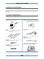
chapter 6 Reference Information
6.1 Tool for Troubleshooting ………………………………………… 6-1
6.2 Acronyms and Abbreviations …………………………………… 6-2
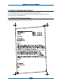
6.3 A4 ISO 19752 Standard Pattern ………………………………… 6-3
attached Parts Catalog
Precautions
1. Precautions
In order to prevent accidents and to prevent damage to the equipment please read the precautions listed
below carefully before servicing the printer and follow them closely.
1.1 Safety Warning
(1) Only to be serviced by appropriately qualified service engineers.
High voltages and lasers inside this product are dangerous. This printer should only be serviced by a
suitably trained and qualified service engineer.
(2) Use only Dell replacement parts
There are no user serviceable parts inside the printer. Do not make any unauthorized changes or
additions to the printer, these could cause the printer to malfunction and create electric shock or fire hazards.
(3) Laser Safety Statement
The Printer is certified in the U.S. to conform to the requirements of DHHS 21 CFR, chapter 1 Subchapter
J for Class 1(1) laser products, and elsewhere, it is certified as a Class I laser product con-forming to the
requirements of IEC 825. Class I laser products are not considered to be hazardous. The laser system
and printer are designed so there is never any human access to laser radiation above a Class I level
during normal operation, user maintenance, or prescribed service condition.
Warning >> Never operate or service the printer with the protective cover removed from Laser/
Scanner assembly. The reflected beam, although invisible, can damage your eyes.
When using this product, these basic safety pre-cautions should always be followed to
reduce risk of fire, electric shock, and injury to persons.
Service Manual
1-1
Precautions
1.2 Caution for safety
1.2.1 Toxic material
This product contains toxic materials that could cause illness if ingested.
(1) If the LCD control panel is damaged it is possible for the liquid inside to leak. This liquid is toxic. Contact
with the skin should be avoided, wash any splashes from eyes or skin immediately and contact your
doctor. If the liquid gets into the mouth or is swallowed see a doctor immediately.
(2) Please keep Drum cartridge and Toner Cartridge away from children. The toner powder contained in the
Drum cartridge and Toner Cartridge may be harmful and if swallowed you should contact a doctor.
1.2.2 Electric Shock and Fire Safety Precautions
Failure to follow the following instructions could cause electric shock or potentially cause a fire.
(1) Use only the correct voltage, failure to do so could damage the printer and potentially cause a fire or
electric shock.
(2) Use only the power cable supplied with the printer. Use of an incorrectly specified cable could cause the
cable to overheat and potentially cause a fire.
(3) Do not overload the power socket, this could lead to overheating of the cables inside the wall and could
lead to a fire.
(4) Do not allow water or other liquids to spill into the printer, this can cause electric shock. Do not allow
paper clips, pins or other foreign objects to fall into the printer these could cause a short circuit leading to
an electric shock or fire hazard.
(5) Never touch the plugs on either end of the power cable with wet hands, this can cause electric shock.
When servicing the printer remove the power plug from the wall socket.
(6) Use caution when inserting or removing the power connector. The power connector must be inserted
completely otherwise a poor contact could cause overheating possibly leading to a fire. When removing
the power connector grip it firmly and pull.
(7) Take care of the power cable. Do not allow it to become twisted, bent sharply round corners or other
wise damaged. Do not place objects on top of the power cable. If the power cable is damaged it could
overheat and cause a fire or exposed cables could cause an electric shock. Replace a damaged power
cable immediately, do not reuse or repair the damaged cable. Some chemicals can attack the coating on
the power cable, weakening the cover or exposing cables causing fire and shock risks.
(8) Ensure that the power sockets and plugs are not cracked or broken in any way. Any such defects should
be repaired immediately. Take care not to cut or damage the power cable or plugs when moving the
machine.
(9) Use caution during thunder or lightening storms. Dell recommend that this machine be disconnected from
the power source when such weather conditions are expected. Do not touch the machine or the power
cord if it is still connected to the wall socket in these weather conditions.
(10) Avoid damp or dusty areas, install the printer in a clean well ventilated location. Do not position the
machine near a humidifier. Damp and dust build up inside the machine can lead to overheating and
cause a fire.
(11) Do not position the printer in direct sunlight. This will cause the temperature inside the printer to rise
possibly leading to the printer failing to work properly and in extreme conditions could lead to a fire.
(12) Do not insert any metal objects into the machine through the ventilator fan or other part of the casing, it
could make contact with a high voltage conductor inside the machine and cause an electric shock.
Service Manual
1-2
Precautions
1.2.3 Handling Precautions
The following instructions are for your own personal safety, to avoid injury and so as not to damage the
printer
(1) Ensure the printer is installed on a level surface, capable of supporting its weight. Failure to do so could
cause the printer to tip or fall.
(2) The printer contains many rollers, gears and fans. Take great care to ensure that you do not catch your
fingers, hair or clothing in any of these rotating devices.
(3) Do not place any small metal objects, containers of water, chemicals or other liquids close to the printer
which if spilled could get into the machine and cause damage or a shock or fire hazard.
(4) Do not install the machine in areas with high dust or moisture levels, beside on open window or close to a
humidifier or heater. Damage could be caused to the printer in such areas.
(5) Do not place candles, burning cigarettes, etc on the printer, These could cause a fire.
1.2.4 Assembly / Disassembly Precautions
Replace parts carefully, always use Dell parts. Take care to note the exact location of parts and also
cable routing before dismantling any part of the machine. Ensure all parts and cables are replaced correctly.
Please carry out the following procedures before dismantling the printer or replacing any parts.
(1) Check the contents of the machine memory and make a note of any user settings. These will be erased if
the mainboard or network card is replaced.
(2) Ensure that power is disconnected before servicing or replacing any electrical parts.
(3) Disconnect printer interface cables and power cables.
(4) Only use approved spare parts. Ensure that part number, product name, any voltage, current or
temperature rating are correct.
(5) When removing or re-fitting any parts do not use excessive force, especially when fitting screws into
plastic.
(6) Take care not to drop any small parts into the machine.
(7) Handling of the OPC Drum
- The OPC Drum can be irreparably damaged if it exposed to light.
Take care not to expose the OPC Drum either to direct sunlight or to fluorescent or incandescent
room lighting. Exposure for as little as 5 mins can damage the surface? photoconductive properties
and will result in print quality degradation. Take extra care when servicing the printer. Remove the
OPC Drum and store it in a black bag or other lightproof container. Take care when working with the
covers(especially the top cover) open as light is admitted to the OPC area and can damage the OPC
Drum.
- Take care not to scratch the green surface of OPC Drum Unit.
If the green surface of the Drum Cartridge is scratched or touched the print quality will be compromised.
Service Manual
1-3
Precautions
1.2.5 Disregarding this warning may cause bodily injury
(1) Be careful with the high temperature part.
The fuser unit works at a high temperature. Use caution when working on the printer. Wait for the fuser to
cool down before disassembly.
(2) Do not put finger or hair into the rotating parts.
When operating a printer, do not put hand or hair into the rotating parts (Paper feeding entrance, motor,
fan, etc.). If do, you can get harm.
(3) When you move the printer
This printer weighs 17.7 kg including toner cartridge and cassette. Use safe lifting and handling
techniques. Use the lifting handles located on each side of the machine. Back injury could be caused if
you do not lift carefully.
(4) Ensure the printer is installed safely.
The printer weighs 17.7 kg, ensure the printer is installed on a level surface, capable of supporting its
weight. Failure to do so could cause the printer to tip or fall possibly causing personal injury or damaging
the printer.
(5) Do not install the printer on a sloping or unstable surface. After installation, double check that the printer
is stable.
Service Manual
1-4
Precautions
1.3 ESD Precautions
Certain semiconductor devices can be easily damaged by static electricity. Such components are commonly
called “Electrostatically Sensitive (ES) Devices” or ESDs. Examples of typical ESDs are: integrated circuits,
some field effect transistors, and semiconductor “chip” components.
The techniques outlined below should be followed to help reduce the incidence of component damage
caused by static electricity.
Caution >>Be sure no power is applied to the chassis or circuit, and observe all other safety precautions.
1. Immediately before handling a semiconductor component or semiconductor-equipped assembly, drain
off any electrostatic charge on your body by touching a known earth ground. Alternatively, employ a
commercially available wrist strap device, which should be removed for your personal safety reasons prior
to applying power to the unit under test.
2. After removing an electrical assembly equipped with ESDs, place the assembly on a conductive surface,
such as aluminum or copper foil, or conductive foam, to prevent electrostatic charge buildup in the vicinity
of the assembly.
3. Use only a grounded tip soldering iron to solder or desolder ESDs.
4. Use only an “anti-static” solder removal device. Some solder removal devices not classified as “anti-static”
can generate electrical charges sufficient to damage ESDs.
5. Do not use Freon-propelled chemicals. When sprayed, these can generate electrical charges sufficient to
damage ESDs.
6. Do not remove a replacement ESD from its protective packaging until immediately before installing it. Most
replacement ESDs are packaged with all leads shorted together by conductive foam, aluminum foil, or a
comparable conductive material.
7. Immediately before removing the protective shorting material from the leads of a replacement ESD, touch
the protective material to the chassis or circuit assembly into which the device will be installed.
8. Maintain continuous electrical contact between the ESD and the assembly into which it will be installed,
until completely plugged or soldered into the circuit.
9. Minimize bodily motions when handling unpackaged replacement ESDs. Normal motions, such as
the brushing together of clothing fabric and lifting one’s foot from a carpeted floor, can generate static
electricity sufficient to damage an ESD.
1.4 Super Capacitor or Lithium Battery Precautions
1. Exercise caution when replacing a super capacitor or Lithium battery. There could be a danger of explosion
and subsequent operator injury and/or equipment damage if incorrectly installed.
2. Be sure to replace the battery with the same or equivalent type recommended by the manufacturer.
3. Super capacitor or Lithium batteries contain toxic substances and should not be opened, crushed, or
burned for disposal.
4. Dispose of used batteries according to the manufacture’s instructions.
Service Manual
1-5
Product spec and feature
2. Product spec and feature
2.1 Product Specifications
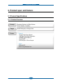
2.1.1 Product Overview
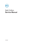
Concept
Target
Feature
Excellent Solution for Office Device
(Fast, Durable, Versatile)
Small Workgroup or Single User
ଖ General
- 35 ppm Print/Copy Speed
- 1200 dpi Print/Copy Resolution
- 256MB System Memory
- 50 sh DADF
- 250 sh Input / 150 sh Output
ଖGOption
- 250 sh SCF
- 802.11 b/g Wireless Lan
Service Manual
2-1
Product spec and feature
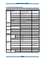
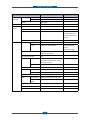
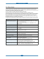
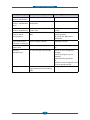
2.1.2 Product General Specifications
Item
General
DELL Laser MFP 2355dn
Major Features
Remarks
Fax, Copier, Print, Scan, DADF,
N/W Print, Scan to USB Key
Size (W*D*H) w/o Hand Set
465.2mmx 463.5mmx460.3mm
(18.3”x18.2”x18.1”)
Net Weight(Inc. Toner Cartridge)
20 Kg
Net Weight(exc. Toner Cartridge)
18.8 Kg
Gross Weight(with package)
23 Kg
LCD
4.3 inch touch screen panel
I/O Interface
USB2.0 (High Speed)
MPU
Chorus-3 / 360MHz
System Bus 120MHz
Power
Printing Operation
600Wh
EPA
Consumption
Sleep Mode
18Wh
EPA
Power Switch
Yes
Input Voltage
Low Voltage : 110 ~ 127VAC, 6.5A
Power Supply
back light
High Voltage : 220 ~ 240VAC, 3.5A
Input Frequency
50 / 60Hz(+/- 3Hz)
Printing
52dBA
Copy
54dBA
Standby
30dBA
Warm Up Time
from Sleep Status
Less than 20 seconds
Machine Life
Max. Monthly
Print
35,000 pages
Volume
Scan
1,000 pages
DADF
1,000 pages
Noise
(Duty Cycle)
Average Monthly Print Volume
2,000 pages
Machine Life
200,000 pages or 5 years whichever
comes first
Periodic
Pickup Roller
150,000 Pages
Replacing
Pad Unit (Tray)
100,000 Pages
Parts
Dell confirm 100,000
Pages reliability.
Pad Unit (DADF)
50,000 Pages
DADF Pick-up Roller :
80K
Environmental
Service Manual
Transfer Roller
70,000 Pages
Fuser Unit
80,000 Pages
Temperature
Operating
10~32ଇ
Non Operating
-20~40ଇ
2-2
Product spec and feature
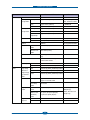
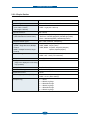
Item
Environmental
Humidity
(Continued)
DELL Laser MFP 2355dn
Operating
20~80%
Non Operating
10~90%
Altitude
Remarks
Max 8,200ft
EMI Approval
Class B
Device
Standard / Max.
256MB / 512MB(Std./Max)
Memory
Type
DDR2
Expand Memory Slot, Type
DDR2 SDRAM DIMM
A general personal
computer memory will
not work. Do not use PC
memory.
PRINT
Compression Technology
YES
Print Speed
Simplex
35ppm/Ltr, 33ppm/A4 (600 dpi)
Duplex
18ipm/Ltr, 17ipm/A4(600dpi)
Usable paper sizes
(Letter,
A4,Folio,Oficio,Legal)
Print Emulation
PCL6, PCL5e
PostScript Level3(Clone)
Auto Emulation Sensing
YES
Font
136 scalable PS3 fonts
Type
93 scalable, including OCR-A, OCR-B; 1
bitmapped PCL Font
Number
Power Save
Resolution
Yes (5/10/15/30/60/120 min)
Normal
600x600dpi (1200x1200)
RET
No
Toner Save
FPOT
Yes
No
From Stand by
Approx. 8.5 seconds (From LSU 'ON')
From Sleep
Less than 24 seconds
Status
Service Manual
Duplex Print
Yes
Printable Area
208 x 273 mm (Letter)
Halftone(Gray Scale)
256levels
2-3
Refer to the attached file.
Product spec and feature
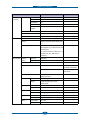
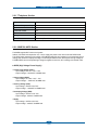
Item
SCAN
DELL Laser MFP 2355dn
Scan Method
Scan Speed
Remarks
Color CCD
Linearity
Approx. 15sec (USB 2.0)
through DADF
USB 2.0, 300dpi, Letter
Size, Pentium 4 2.XGHz,
Gray
Approx. 20sec (USB 2.0)
Color
Approx. 30sec (USB 2.0)
Scan Speed
Linearity
Approx. 15sec (USB 2.0)
through Platen
Gray
Approx. 20sec (USB 2.0)
Color
Approx. 30sec (USB 2.0)
128MB RAM
75dpi/300dpi
Resolution
Optical
600*600dpi
Enhanced
4800dpi*4800dpi
Halftone
Scan Size
256level
Max. Document
75, 300, 600dpi horizontal
for only optical resolution
Max.216mm(8.5")
Width
Effective Scan
Max 208mm(8.2inch)
Width
Scan-to
Scan to Application/Network/Email/USB
Key
Scan To Email Locations
399 locations in the Directory with Search,
Edit and Store facilities
Scan Depth
COPY
Color
24 bit
Mono
1bit for Lineart, 8 Bit for Gray scale
Copy Quality
Text
300x300 dpi (DADF), 600x600 dpi (Platen)
Selection or
Text/Photo
300x300 dpi (DADF), 600x600 dpi (Platen)
Photo
300x300 dpi (DADF), 600x600 dpi (Platen)
Stand by
Approx. 8.5 seconds :Platen
Original Image
type selection
Mode
FCOT
Approx. 15 seconds :DADF
From Sleep
40 seconds
Status
Copy Speed
SDMC at all
/ Letter
mode
35cpm/Ltr, 33cpm/A4
Multiple Copy
MDSC at Text,
21 cpm/Ltr, 20 cpm/A4 (Simplex)
MDSC: Multi-document
Text/Photo,
7 cpm/Ltr, 6 cpm/A4 (Duplex)
Single Copy
Photo
Service Manual
SDMC: Single Document
Origin
Platen
REAR LEFT
Alignment
DADF
Center
2-4
Product spec and feature
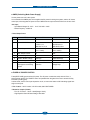
Item
COPY
DELL Laser MFP 2355dn
Zoom Range
Remarks
25% to 400% for Platen
(Continued)
25% to 100% for DADF
Number of Copies
1~199
Preset
Yes
Contrast Levels
5 level
Copy Mode(=Quality)
Text, Text/Photo, Photo
Collation Copy
Yes
Auto return to default mode
Yes
Time can be changeable ;
15,30,60,180sec, Off
Changeable Default mode
Contrast, Image, Reduce/Enlarge,
No. of Copies
Special Copy
N-up copy
2-up, 4-up (DADF only)
Collation Copy
Yes (DADF only)
Auto Fit Copy
Yes(Platen only)
ID Copy
Yes(Platen only)
* Copy 2-side printed
original document into one
page(ex. ID Card Copy)
TELEPHONE
Clone
Yes(Platen only)
Poster
Yes(Platen only)
Handset
No
On hook Dial *
Yes
Search *
Yes(Phone Book)
by using Phone Book
Button(Same as Rocky)
1-Touch Dial *
No
Speed Dial *
400 locations(00~399)
Total locations can be
stored
Service Manual
TAD I/F
Yes
Tone/Pulse
Selectable in Technical Mode
Pause
Yes
Auto Redial
Yes
Last Number Redial
Yes
Distinctive Ring
Yes
Caller ID
No
External Phone Interface
Yes
Report & List
Tx/Rx Journal
Yes
Print out
Confirmation
Yes
Help List
No
Auto Dial List
Yes
2-5
Product spec and feature
Item
TELEPHONE
(Continued)
Fax
DELL Laser MFP 2355dn
Remarks
System Data List Yes
Sound Control
Ring Volume
Yes(Off, Low, MED, HIGH)
Key Volume
Yes(On, Off)
Alarm Volume
Yes(On, Off)
OHD Volume
Yes
Speaker
Yes(On, Off, Comm.)
7 steps adjustable
Compatibility
ITU-T G3
Communication System
PSTN/PABX
Modem Speed
33.6Kbps
TX Speed
3sec
LRT/MMR/CCITT No.1
Chart/33.6Kbps
Compression
MH/MR/MMR/JPEG/JBIG
Color Fax
Yes(Sending Only)
ECM
Yes
Resolution
Std
203*98dpi
Fine
203*196dpi
S.Fine
300*300dpi
Scan
Std
2.5 sec/ LTR
Speed(DADF)
Fine/S.Fine
5 sec/ LTR
Changeable Default mode
Darkness, Original Type, Reduce/Enlarge,
No. Of Copies
Rx fax duplex print out
Yes
Multiple page scan speed
21 ppm/LTR, Std mode
Receive Mode
Fax, TEL, Ans/Fax( DRPD)
Memory
Capacity
4MB
Optional Memory No
Max locations to
399 locations
store to 1 Group
Dial
Fax Forward
Yes(On/Off)
Broadcasting
up to 409 locations
Cover page
Yes
Delayed fax
Yes
Fax Forward to
Yes (Enable / Disable),max 10 locations
Email Addresses
Functions
Service Manual
Memory RX
Yes
Voice Request
No
TTI
Yes
2-6
203×98dpi, ITU-T #1
Product spec and feature
Item
DELL Laser MFP 2355dn
Fax
RTI
Yes
(Continued)
Polling
No
Earth/Recall
No
Auto Reduction
Yes
F/W Remote
Yes
Remarks
upgrade
Network
Junk Fax barrier
Yes
Secure Receive
Yes
Memory Back-up
Yes (Flash ROM)
Option
Wired(Default), Wireless (Optional)
Protocol
SPX/IPX, TCP/IP, Ethertalk, SNMP, HTTP
1.1
Operating System
MS Windows 2000/XP/2003/Vista/2008,
MAC (English only, no status monitor, web
download only)
Linux: Red Hat 8.0~9.0, Fedora Core 1~3,
Mandrake 9.0~10.2, SuSE 8.2~9.2.
Netware 4.x
Paper Handling Capacity
( 20lbs)
Main Tray
250sheets
Bypass
50 Sheets
Optional Cassette
250sheets
Output Capacity
Face Down: 150Sheets/20lb
5 sheets for OHP, Label,
Cut Sheet and Envelope
Face Up: 1Sheet
Mainly for Envelope and
Thick Paper
Output Control
Face Up/Down controlled manually by
opening rear cover
Paper Size
Main Tray
A4,Letter,Legal,Folio, Executive, B5
Bypass
Bypass:Envelope6 3/4,7 3/4,#9,
#10,DL,C5,B5
Paper Weight
Paper Path
Paper Size
DADF
Service Manual
Main Tray
16~24 lb.
Bypass
16~43 lb.
Standard output
Bottom to Middle Front (FIFO)
Straight Through
Face up, Single Sheet
Max
216 x 356mm(8.5"x14")
Min
76 x 127mm(3"x5")
Paper Weight
12.5~28lb
Capacity
50 sheets
2-7
Product spec and feature
Item
DELL Laser MFP 2355dn
Paper Handling
Document Size
(Continued)
Width
Document Size
Remarks
142mm - 216mm(5.6" - 8.5")
148 mm - 356mm(5.8" - 14.0")
Length
Document
0.075mm – 0.13mm(0.003” – 0.005”)
Thickness
Jam Rate
Cassette,
1/4000, Duplex(2500)
*In H/H and L/L condition,
the spec. of JAM rate,
Mis-pickup rate and MultiFeed rate are doubled.
2nd Feeder
Cassette : Jam:1/2000,
Double Feed : 1/1000
DADF
1/1000, Duplex(1/500)
Multi-Feed
Cassette,
1/2000,
Rate
2nd Feeder
Printing Skew
DADF
1/1000
Top
±1.5/177.8mm (1st Tray)
±2.5/177.8mm (2nd Tray)
±2.5/177.8mm (Duplex)
Side
±2/241.3mm (1st Tray)
±2.5/241.3mm (2nd Tray)
±2.5/241.3mm (Duplex)
Copy Skew
Top
±3.0/190mm
Side
±3.0/277mm (Simplex & Tray1/MP)
±3.5/277mm (Duplex, Tray2)
Software
Compatibility
WHQL
Service Manual
DOS
No
Win 3.x
No
Win 95
No
Win 98
No
Win ME
No
Win NT 4.0
No
Win 2000
Yes
Win 2003
Yes
Including 64bits
Win XP
Yes
Including 64bits
Win Vista
Yes
Including 64bits
Win 2008
No
Including 64bits
Mac
Yes, English only web version
Linux
Yes, English only
MFP
Yes for XP,2003,Vista,2008
2-8
Product spec and feature
Item
Software
Driver
(Continued)
DELL Laser MFP 2355dn
Printer
PCL6, PostScript Level3(Std.)
TWAIN
Yes
WIA
Yes
PSU
Yes
PC-FAX
Yes
Remarks
PC fax including to
network fax
Consumables
Type
One Piece Type Toner Cartridge
How to install
Front door open and front loading
Toner
Life
Initial 3Kpages (5% ISO 19752Test
Pattern)
running Standard: 3Kpages
High yield: 6 K pages
Level Sensor
Quality Target
Service Manual
No
Toner Count
Yes (Dot Counter)
MTBF
14 months at Recommended Duty Cycle
MPBF
30,000 pages
MTTR
30 Minutes
UMR
33.350 Per million pages
2-9
Product spec and feature
2.2 System Outline
This document is the product specification for Dell 2135dn. Dell 2135dn is a Multi-Function Peripheral
(MFP) integrating a plain fax, a B/W laser printer, a color flatbed scanner, and a B/W copier. Dell 2135dn is
developed for small workgroup and personal office customers. The main product concept is “High Speed and
High Quality.” This model has 27ppm print-speed, 3 sec transmission-speed for fax, 33.6kbps fax-transfer
rate, optical 600 dpi color scanner, and 1200 dpi printer.
Dell 2135dn is developed to meet standard approvals of FCC Part 15 Class B, FCC Part 68, IC 60950, and
cUL for the US and Canada. Other markets covered are Europe, Latin America and Emerging Markets.
Agency Certifications will be attained to enable launch in all target markets
2.2.1 System Configurations
DELL LASER MFP 2355dn is made up of the Main Control part, Operation Panel part, Scanner part, Line
Interface part and Power part. Each Part is a separate Module which focuses on common and standard design
of different kind products. Main control part adopting Fax & LBP Printer exclusive Controller is composed of
1 CPU and 1 Board. Scanner part is composed of DADF and Platen and is connected with Main by Harness.
Line Interface part is designed to apply TBR21 standard (Domestic, Europe, etc.)
2.2.1.1 CPU Part
1) CPU : ARM926EJS CORE, which is exclusive controller to execute Printer & FAX Function and to
execute operation block by flash memory within system program, and to control whole system.
· Main function block
· Completely Integrated System for Embedded Applications
· Operation Frequency : CPU Core -> over 360MHz, System Bus -> 120MHz
· Operation Voltage : Core Voltage -> 1.0V, I/O Pad Voltage -> 3.3V, RTC Voltage -> 2.5V
2) Flash Memory : Record System Program, and download System Program by PC INTERFACE.
FAX for Journal List, and Memory for One Touch Dial, Speed Dial List.
- size : 32M Byte (NOR Flash), 1M Byte (NOR Flash), 4M Byte (Serial Flash)
- Access Time: 90ns (Max)
- Page Access Time: 25ns (Max)
3) SDRAM : is used as Swath Buffer in Printing, Scan Buffer in Scanning, ECM Buffer in FAX receiving, and
System Working Memory Area (DDR2 DIMM)
- size : 256M Byte(Default)
512M Byte(Option)
- Max Frequency : 166MHz
Service Manual
2-10
Product spec and feature
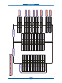
2.2.1.2 FAX Section
1) Modem Part
BLOCK DIAGRAM
Implemented by based on Silab DAA (Data Access Arrangement) Solution, and is roughly composed of two
kinds Chip Solution
- Si2435 (SSD) : Existing Modem Chip which adds SSD (System Side Device) for interfacing between LSD
- Si3018 (LSD) : LIU (Line Interface Unit) Chip which is controlled by SSD and satisfies each PSTN
Requirements by modulating internal Configuration with connecting Tel Line.
Service Manual
2-11
Product spec and feature
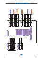
Signal Transition of DAA Solution
1) Line Interface Signal of Tel Line and LSD is Analog Signal.
2) there is A/D, D/A Converter in LSD, so Analog Signal from Tel Line is converted in Digital through A/D
Converter in DAA and transfer to SSD by DIB Capacitor Digital Signal from SSD is converted to Analog by
D/A Converter in DAA and transfer to Tel Line
3) Transformer transfer Clock from SSD to LSD and Clock Frequency is 4.032MHz.
LSD full wave rectifies Clock to use as inner Power supply and also use as Main Clock for DIB Protocol
Sync between LSD and SSD. Transformer transfer Clock by separating Primary and Secondary, and
amplifies Clock Level to LSD by Coil Turns Ratio 1:1.16.
■ Clock
- Clock is supplied by transformer from SSD to LSD, and there is PWROUT to adjust output impedance of
Clock
CLKP
SSD
LSD
CLKN
DIBP
DIBN
Out Driver is inside SSD and CLKSHIGH Resistor to adjust duty of HLPWR Resistor and Clock.
Clock from SSD to LSD has Differential structure of 180 phase difference for Noise Robustness DIB Data
transfer Data from SSD to LSD by Transformer, and also transfer specific data from LSD to SSD.
After transferring data from SSD, RSP is transferred and LSD recognizes RSP and change LSD to output
Driver transfer Data to SSD.
DIB Data form SSD to LSD by Transformer has Differential structure of 180 phase difference between DIBP
and DIBN for Noise Robustness
Service Manual
2-12
Product spec and feature
1) Application Network:
PSTN (RJ-11)
2) Communication Mode:
Half-Duplex, ITU V.8, V.34, V.17, V.29, V.21, V.27ter, ECM
- Modem will auto train down only.
3) Communication Standard:
ITU-T Group 3
4) Max. Modem Speed:
33.6 Kbps
5) Encoding:
MH, MR, MMR, JPEG, JBIG
6) Transfer Rate:
3 seconds (standard resolution, MMR, 33.6kbps, CCITT No.1, LTR)
Under 2sec(JBIG)
- Phase “C” by ITU-T No.1 Chart/Memory Transmission/ECM
7) Fax Modes:
- Standard (203 x 98 dpi)
- Fine (203 x 196 dpi)
- Super Fine (300 x 300 dpi)
8) Fax Contrast:
Adjustable 3 levels (Light/Normal/Dark)
9) Fax Memory:
4MB (About 300 Sheets of CCITT No.1 Chart at standard
resolution). User selectable parameters will be stored in NVRAM.
10) TX/RX Journal :
Available.
11) Tel/ID List:
Available.
12) Confirmation Reports for Send:
- Upon successful transmission
- Upon failure
- Reduced image of first page (except OHD, and partial page for
complexity of the images)
- Customer On/Off selectable
13) Management Reports:
- System Data List
- Image TCR for Memory TX
14) TTI/RTI:
- TTI (Transmit Terminal Identification) printed at top of Fax Image.
- RTI (Receiver Terminal Identification) printed at bottom of Fax
Image the Transmitting devices fax number is substituted for
receiving devices fax number is this footer.
15) Line Control Unit (LIU):
- Input Sensitivity : Not programmable
- Output Level : -9 to -15 dBm (programmable)
- Cable Equalization : Not programmable
- Input/Output Impedance : per PTT requirements (programmable)
- DC Resistance : per PTT requirements (programmable)
- Insulation Resistance : Minimum 5M ohm
- Local Machine date and time
- Local Machine ID
- Local Machine Name
- Transmit page count (3 digits)
16) Header Transmission
(Always On):
Line Interface Part
This is Connection Part between system and PSTN(Public Switched Telephone Network), and primary circuit
is usually located. Main functions are Line Interface, Telephone Connection and Line Condition Monitoring.
Service Manual
2-13
Product spec and feature
2.2.1.3 Scanner Section
Scan Part
1) Pictorial signal input part: output signal of CCD passes through Bypass Cap change to ADC at
DS90DR218A, and defined signal between DS90DR218A and CHORUS3 processes the Image signal.
When AFE accept each pixel, CDS(Correlated Double Sampling ) technique which samples arm-level
twice is used on each pixel by using CIP4e signal.
2) Pictorial image processing part: read CCD Pixel data in terms of 600dpi Line and process Error Diffusion
Algorithm on Text mode and Photo mode, and then store Data at Scan Buffer on PC Scan mode without
algorithm.
On every mode Shading Correction and Gamma Correction are executed ahead, then processing is
executed later.
* Scan Image Control Specification
ཛ Minimum Scan Line Time: 0.75ms
ཛྷ Scan Resolution
: Max. 600DPI
ཝ Scan Width
: 216mm
ཞ main function
- Internal 12bit ADC
- White Shading Correction
- Gamma Correction
- CCD Interface
- 256 Gray Scale
3) CCD Operating Part : CCD Image sensor use +5V and Inverter uses +24V
- CCD Maximum Operating Frequency : 10MHz
- CCD Line time : 0.75ms
- White Data output Voltage : 0.7V±0.5V (Mono Copy, 0.75ms/line)
- Maximum Inverter Current : 600 mA Max.( +24V)
1) Scanning Device:
Color CCD (Charge Coupled Device) Module
2) Supported Operating Systems:
Windows 2000/2003/ XP/Vista/2008, MAC (English only, no status
monitor, web download only)
Mac: PostScript Network Print only
Linux: Red Hat 8.0~9.0, Fedora Core 1~3, Mandrake 9.0~10.2, SuSE
8.2~9.2
3) Compatibility:
TWAIN Standard
4) Maximum Scan Width:
216mm (8.5 inches)
5) Effective Scan Width:
208mm (8.2 inches)
6) Optical Resolution:
600x600 dpi
7) Interpolated Resolution
Maximum 4800 dpi
8) Preview Scan:
75 dpi
Service Manual
2-14
Product spec and feature
9) Scan Modes/Speeds: DADF
(USB 2.0, 300dpi,
Letter Size, Pentium
4 2.xGHz, 128MB
Platen
RAM)
- Linearity : 15 sec. (Letter, 300dpi, USB)
- Gray Scale : 20 sec. (Letter, 300dpi, USB)
- Color : 30 sec. (Letter, 300dpi, USB)
10) DADF Capacity:
50 sheets (20 lb)
11) Image Compression:
None
12) PC Interface:
(USB & Parallel are not
simultaneously supported)
- USB (without HUB mode)
Requires 6 ft. USB Cable (not supplied by SEC)
13) Minimum PC Specification:
Pentium-II 233MHz, 64MB RAM, 120MB free disk space
14) Registration Position for
Original:
- Platen : Rear-Left Corner (when facing front/operator panel).
- DADF : Center
15) Number of Copies:
3 digits (199 maximum for LCD display and reports)
Service Manual
- Linearity : 15 sec. (Letter, 300dpi, USB)
- Gray Scale : 20 sec. (Letter, 300dpi, USB)
- Color : 30 sec. (Letter, 300dpi, USB)
2-15
Product spec and feature
2.2.1.4 OPE Pannel Section
(1) Configuration
Operations Panel uses Main Control and separated OPE Chip Micom and work as inner program,
systemic operation is serial system which exchange Date with UART Port of Main Control. OPE Panel is
approximately composed of Micom part, Matrix part and LCD.
(2) Micom controller
Micom has ROM, RAM, I/O Port built-in and displays and lights LCD by CPU command of Main Control
Part and report Key recognition Data to Main Control Board.
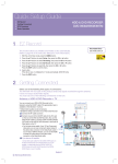
(3) Operator Panel Button Functions
Status LED
Fax keys
Function keys Common keys
Common Keys
Press:
To:
Stop an operation at any time, or return to main menu.
Reverts the current setting to the default values.
Start a job.
Function Keys
Press:
To:
Deletes characters in the edit area.
Shows the jobs currently running.
You can copy both sides of an ID Card, such as a driver’s license, to a single side of
paper.
Gives detailed information about this machine’s menus or status.
Service Manual
2-16
Product spec and feature
Fax Keys
Press:
To:
Dial/Enter number.
(4) Understanding the Status LED
When the problem occurs, the Status LED indicates the machine’s condition by the light color of it’s action.
Status
Description
Off
• The machine is off-line.
• The machine is in power save mode. When data is received, or any button is
pressed, it switches to on-line automatically.
Green
Red
Service Manual
Blinking
The machine is warming up or ready to receive the data.
On
The machine is on-line and can be used.
Blinking
• A minor error has occurred and the machine is waiting for the error to be
cleared. Check the display message. When the problem is cleared, the
machine resumes.
• The toner cartridge is low. Order a new toner cartridge. You can temporarily
improve print quality by redistributing the toner.
• The toner cartridge is totally empty. Remove the old toner cartridge and install
a new one.
• A paper jam has occurred.
• There is no paper in the tray. Load paper in the tray.
• The machine has stopped due to a major error. Check the display message.
2-17
Product spec and feature
2.2.1.5 Printer Section
Printer is consisted of the Engine parts and F/W, and engine parts is consisted of the mechanical parts
comprising Frame, Feeding, Developing, Driving, Transferring, Fusing, Cabinet and H/W comprising the main
control board, power board, operation panel, PC Interface.
The main controller is consisted of ASIC parts, Memory parts, Engine
Interface parts and it functions as Bus Control, I/O Handling, drivers & PC Interface by CPU.
The Engine Board and the Controller Board are in one united board, and it is consisted of CPU part and print
part in functional aspect. The CPU is functioned as the bus control, I/O handling, drivers, and PC interface.
The main board sends the Current Image, Video data to the LSU and manages the conduct of Electro
photography for printing. It is consisted of the circuits of the motor (paper feed, pass) driving, clutch driving,
pre-transfer lamp driving, current driving, and fan driving.
The signals from the paper feed jam sensor and paper empty sensor are directly inputted to the main board.
1) Printing Method:
Laser-based Electro-photography
2) Supported Operating Systems:
Windows 2000/2003/XP/Vista/2008/ MAC (English only, no status
monitor, web download only)
Linux: Red Hat 8.0~9.0, Fedora Core 1~3, Mandrake 9.0~10.2,
SuSE 8.2~9.2
3) Emulation:
PCL6, PS3,PCL5e
4) Maximum Paper Size:
Legal
5) Effective Printing Width:
- Letter/Legal : 208mm
- A4 : 202mm
6) Resolution:
(selectable from Print Driver)
- Addressable 1200 x1200 dpi
- 600x600 dpi (True; no RET)
7) Speed:
35ppm (Letter)
8) Input Paper Capacity:
- Tray : 250 sheets (20 lb)
- Bypass : 50 sheets (20 lb)
9) Output Paper Capacity:
150 sheets (20 lb; sequenced 1 to N, face down)
10) Feed Direction:
Front In, Front Out (FIFO)
11) PC Interface:
- USB 2.0(without HUB mode)
Requires 6 ft. USB Cable (not supplied by SEC)
12) Toner Cartridge:
- Toner Low Sensor : None
- Toner Low Indicator : Message displayed on LCD
- Cartridge Missing Indicator : Message displayed on LCD
13) Paper Sensing:
- Tray : “Add Paper” message displayed on LCD
- Bypass : “Add Paper” message displayed on LCD
Service Manual
2-18
Product spec and feature
2.2.1.6 Copier Section
1) Copy Mode:
Black and White
2) Scanner Type;
CCD with Flatbed/Platen and DADF
3) Maximum Size of Original:
(max. width = 218 mm,
max length = 400 mm)
- Platen : 216 x 297 mm
- DADF : Legal (216 x 356 mm)
4) Optical Resolution:
600 x 600 dpi
5) Copy Quality - H x V:
(User selectable via Content button)
- Text : 300x300 dpi(DADF), 600x600 dpi (Platen)
- Text/Photo : 300x300 dpi(DADF), 600x600 dpi (Platen)
- Photo : 300x300 dpi(DADF), 600x600 dpi (Platen)
6) Supported Media Types:
Plain, Label, Cardstock, Transparency
7) Copy Speed:
(SDMP = Single Document, Multiple
Printout,
MDSP = Multiple Document, Single
Printout)
- Platen, SDMP : 35cpm (Letter)
- DADF, SDMP : 35cpm (Letter)
- DADF, MDSP : 21cpm/Ltr, 20cpm/A4 (Simplex)
7ipm/Ltr, 6ipm/A4 (Duplex)
8) Reduce/Enlarge:
- Platen : 25% - 400% (1% increments)
- DADF : 25% - 100% (1% increments)
9) Non-printable Area:
6 mm (Top, Bottom, and each Side)
1 to 199
10) Copy Count:
(Page count displayed on LCD during
copy operation)
11) Copy Modes:
Text, Text/Photo, Photo
12) Fixed R/E Setting:
100%, Auto-fit, 2(4)-Up
13) Darkness Control:
5 levels
14) First Copy Output Time (FCOT):
- Platen : 8.5 sec. (600 x 600 dpi)
- DADF : 15 sec. (600 x 600 dpi)
15) Duplex Copy
1 → 1 Sided
1 → 2 Sided Long Edge
1 → 2 Sided Short Edge
2 → 1 Sided Long Edge
2 → 1 Sided Short Edge
2 → 2 Sided Long Edge
Service Manual
2-19
Product spec and feature
2.2.1.7 Telephone Section
1) Speed Dial:
400 Locations (46 digits maximum per location)
2) On-hook Dial (manual fax):
Yes
3) Last Number Redial:
Yes
4) Automatic Redial:
Yes
5) Pause:
Yes
6) Ringer Volume:
Off, Low, Medium, High
7) Tone/Pulse:
Selectable (Tech Mode Only no Telecom certification for Pulse mode)
2.2.1.8 SMPS & HVPS Section
The SMPS supplies DC Power to the System.
It takes 110V/220V and outputs the +5V, +24V to supply the power to the main board and DADF board.
The HVPS board creates the high voltage of THV/MHV/Supply/Dev and supplies it to the developer part for
making best condition to display the image. The HVPS part takes the 24V and outputs the high voltage for
THV/MHV/BIAS, and the outputted high voltage is supplied to the toner, OPC cartridge, and transfer roller.
■ HVPS (High Voltage Power Supply)
• Transfer High Voltage (THV+)
- Input Voltage: 24 V DC +15% / -10%
- Output Voltage: +1300V±3% at 200MΩ load
• Charge Voltage (MHV)
- Input Voltage : 24 V DC +15% / -10%
- Output Voltage : -1350V±3% at 50MΩ load
• Cleaning Voltage (THV-)
- Input voltage : 24VDC+15%/-10%
- Output voltage : -1200±20% at 200MΩ load
• Developing Voltage (DEV)
- Input Voltage : 24VDC+15%/-10%
- Output Voltage: -330±3% at 50MΩ load
• Supply
- Input voltage : 24VDC+15%/-10%
- Output voltage : -530±3% at 50MΩ load
Service Manual
2-20
Product spec and feature
■ SMPS (Switching Mode Power Supply)
It is the power source of entire system.
It is consisted of the SMPS part, which supplies the DC power for driving the system, and the AC heater
control part, which supplies the power to fuser. SMPS has two output channels. Which are 5V and +24V.
• AC Input
- Input Rated Voltage: AC 110V ~ 127V / AC 220V ~ 240V
- Rated Frequency : 50/60 Hz
• Rated Output Power
NO
ITEM
CH1
CH2
1
CHANNEL NAME
+5V
+24.0V
2
CONNECTOR PIN
CON 3
5V PIN: 11,13
GND PIN: 12,14,16
CON 3
24V PIN:3,5,7,9
GND PIN:4,6,8,10
3
Rated Output
+5V ± 5%
(4.75 ~ 5.25V)
+24V ± 10%
(21.6 ~ 26.4V)
4
Max. Output Current
3A
4.0A
5
Peak Loading Current
3.6A
10.0A
6
RIPPLE NOISE Voltage
100mVp-p
Under 500mVp-p
7
Maximum output
15W
96W
8
Protection for loading
shortage and overflowing
current
Shut down or Fuse
Protection
Shut down or Output
Voltage Drop
Remark
1ms
■ FUSER AC POWER CONTROL
Fuser(HEAT LAMP) gets heat from AC power. The AV power controls the switch with the Triac, a
semiconductor switch. The ‘ON/OFF control’ is operated when the gate of the Triac is turned on/off by
Phototriac (insulting part).
In other words, the AC control part is passive circuit, so it turns the heater on/off with taking signal from
engine control part.
• Triac feature : 16A-LV model / 12A-HV model, 600V SWITCHING
• Phototriac Coupler (PC501)
- Turn On If Current : 15mA ~ 50mA(Design: 16mA)
- High Repetive Peak Off State Voltage : Min 600V
Service Manual
2-21
Disassembly and Reassembly
3. Disassembly and Reassembly
3.1 General Precautions on Disassembly
When you disassemble and reassemble
components, you must use extreme caution. The
close proximity of cables to moving parts makes
proper routing a must.
If components are removed, any cables disturbed
by the procedure must be restored as close as
possible to their original positions. Before removing
any component from the machine, note the cable
routing that will be affected.
Releasing Plastic Latches
Many of the parts are held in place with plastic
latches. The latches break easily; release them
carefully.
To remove such parts, press the hook end of the
latch away from the part to which it is latched.
Whenever servicing the machine, you
must perform as follows:
1. Check to verify that documents are not stored in
memory.
2. Be sure to remove the toner cartridge before you
disassemble parts.
3. Unplug the power cord.
4. Use a flat and clean surface.
5. Replace only with authorized components.
6. Do not force plastic-material components.
7. Make sure all components are in their proper
position.
Service Manual
3-1
Disassembly and Reassembly
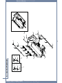
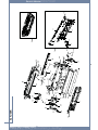
3.2 General Disassembly
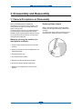
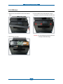
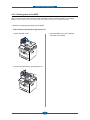
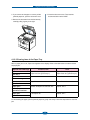
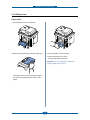
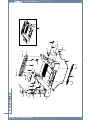
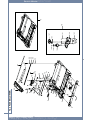
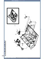
3.2.1 Cover
1. 1. Take out the Cassette Unit from SET.
4. Remove the Duplex Guide from the rear side of
SET.
Duplex Guide
Cassette Unit
2. Open the front cover. And take out the Toner
Cartridge.
5. To remove the Cover-Rear, first remove CoverDIMM.
Toner Cartridge
Cover-DIMM
3. Separate the front cover from locking by pulling
in the direction of arrow.
6. Remove the 4 screws as shown below.
Cover-Rear
Cover-Front
Service Manual
3-2
Disassembly and Reassembly
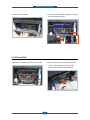
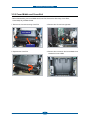
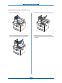
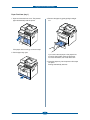
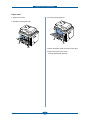
7. Remove the Cover-Rear.
8. Remove the Cover-Side(Left,Right) by removing
the 3 hook from the bottom.
Cover-Side Right
Cover-Side Left
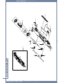
3.2.2 Fuser-Unit
1.Open the Cover-Rear. And remove the 4 screws.
2. Take out the Fuser-Unit with holding the lever.
ଖGGIf you want to repair the sub unit of Fuser,
please consult the Fuser exploded view.
Fuser-Unit
Service Manual
3-3
Disassembly and Reassembly
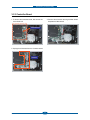
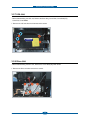
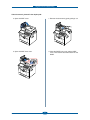
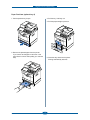
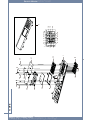
3.2.3 Controller Board
1. To remove the Controller board, first remove the
Cover-Side Left.
3. Remove the all screws securing the Main shield.
Separate the Main shield.
Controller B’d
2. Unplug the all harness from the Controller board.
Harness
Service Manual
3-4
Disassembly and Reassembly
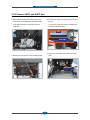
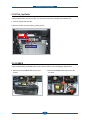
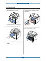
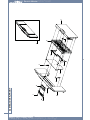
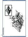
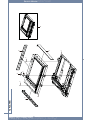
3.2.4 Scanner ASS’Y and DADF Unit
1. Before disassembling Scan Assy, Remove the
Cover-Rear, Cover-Side(L/R), and Main Shield.
3. Pull the Scan Assy in the direction of arrow and
Lift up it.
ଖ Scan ASS’Y consists of the DADF-Unit and
OPE-Unit
ଖ If you want to repair the sub unit of DADF-Unit,
consult the Exploded view.
DADF
Scan ASS’Y
4. Open the Cover-DADF and remove the DADF
roller.
2. Remove the 2 screws from the rear side of SET.
DADF-Roller
Service Manual
3-5
Disassembly and Reassembly
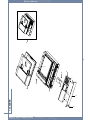
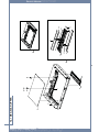
3.2.5 OPE-Unit
1. Remove the Cover-OPE Front from the Scanner
Assy.
3. Turn the OPE-Unit up with attention to hook.
Unplug the connector and release the OPE-Unit.
Caution : Do not overpower to remove the hook.
It is easy to break the hinge.
2. Remove the 3 screws.
Service Manual
3-6
Disassembly and Reassembly
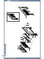
3.2.6 Cover-Middle and Cover-Exit
- Before disassembling the Cover-Middle and Cover-Exit, Remove the Scan Assy, Cover-Rear,
Cover-Side(L/R), and Main Shield.
1. Remove the 2 screws securing Cover-Exit.
3. Remove the 1 Screw from right side.
Cover-Middle
Cover-Exit
2. Separate the Cover-Exit.
Service Manual
4. Remove the 7 screws on the Cover-Middle. And
release the Cover-middle.
3-7
Disassembly and Reassembly
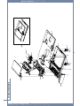
3.2.7 LSU-Unit
- Before disassembling the LSU unit, Remove the Scan Assy, Cover-Rear, Cover-Side(L/R),
Cover-Exit, Cover-Middle.
1. Remove the LSU unit after the 2 harness and 4 screws.
LSU-Unit
3.2.8 Drive-Unit
- Before disassembling the Drive unit, Remove the Cover-Side(L/R), Main shield.
1. Remove the Drive unit after remove the 5 screws.
Service Manual
3-8
Disassembly and Reassembly
3.2.9 Pick_Up Roller
- Before disassembling the Pick up roller, You must remove the Toner cartridge and Cassette Unit.
1. First turn upside down the SET.
2. Remove the Pick up roller rubber by pulling a hook.
Hook
Pick_Up Rubber
3.2.10 SMPS
- Before disassembling the SMPS board, remove the Cover-Rear, Cover-Side(Right), Duplex Motor.
1. Remove the Cover-SMPS after remove the 2
screws.
Service Manual
2. Remove the SMPS Shield after remove the
2 screws.
3-9
Disassembly and Reassembly
3.2.11 HVPS
- Before disassembling the HVPS board, You must remove the Toner cartridge, Cassette Unit,
Pick-Up roller Assy, Duplex Motor. And turn upside down the SET.
1. Separate the HVPS Shield after remove the 8 screws.
Caution : When disassembling and assembling the HVPS Shield, be careful the harness of the Cassette
Sensor.
3.2.12 Transfer Roller
- Before disassembling the Transfer roller, remove the toner cartridge.
1. Remove the Transfer roller.
Caution : Do not touch the surface of the Transfer Roller.
Transfer Roller
Service Manual
3-10
Alignment and Troubleshooting
4. Alignment and Troubleshooting
4.1 Alignment and Adjustments
This chapter describes the main functions for service, such as the product maintenance method, the test
output related to maintenance and repair, DCU using method, Jam removing method, and so on. It includes
the contents of manual.
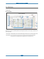
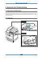
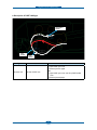
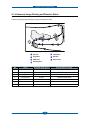
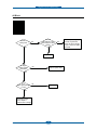
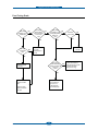
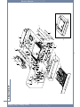
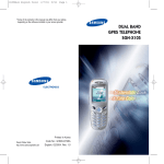
4.1.1 Paper path
Scanner Part
PAPER EMPTY
SENSOR
FEED
SENSOR
SCAN
SENSOR
Engine Part
Roller-Exit
Roller-Heat
Roller-REGI
Roller-MP
OPC
Roller-Transfer
Duplex
Roller-Feed
Roller-Pickup
Service Manual
4-1
Roller-Pressure
Alignment and Troubleshooting
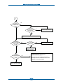
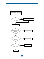
4.1.2 Clearing Paper Jams
Occasionally, paper can be jammed during a print job. Some of the causes include:
• The tray is loaded improperly or overfilled.
• The tray has been pulled out during a print job.
• The front cover has been opened during a print job.
• Paper was used that does not meet paper specifications.
• Paper that is outside of the supported size range was used.
If a paper jam occurs, LCD window will show it’s speeds. Find and remove the jammed paper. If you don’t
see the paper, open the covers.
Do not use a pinset or a sharp metal tool when removing a jam.
The covering of a metal part can be removed which can cause an electric leakage.
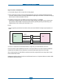
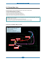
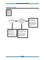
■ Description of ENGINE JAM type (Layout)
(1) JAM-0
JAM- : Paper empty sensor ~ Feed sensor
(2) JAM-1 : Feed sensor ~ Exit sensor
(3) JAM-2 : Exit sensor ~
(4) Duplex Jam-1 : ~ Duplex sensor
(5) Duplex Jam-0 : Duplex sensor ~ Feed sensor
(3)
EXIT SENSOR
SCAN SENSOR
FEED SENSOR
(2)
(5)
(4)
DUPLEX SENSOR
(1)
PAPER EMPTY
SENSOR
Service Manual
4-2
Alignment and Troubleshooting
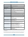
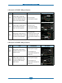
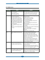
■ Description of ENGINE JAM type (Simplex)
Type
Case
Jam Removal
Leading edge of media does
not arrive at registration within a
certain time after pick-up(If fails
at a time,it tries pick-up again)
1. Pull out cassette
2. Remove jammed paper
Jam 1
Leading edge of media does not
arrive at Exit Sensor within a
certain time after registration
1. Open front cover
2. Pull out toner cartridge
3. Remove jammed paper
Jam 2
1. Open rear cover
Trailing edge of media does not 2. Pull down jam lever on fuser
unit and open fuser cover)
leave Exit Sensor within a certain
3. Remove jammed paper from
time after touching registration
exit
Jam 0
Jam Layout
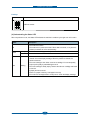
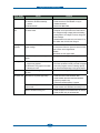
■ Description of ENGINE JAM type (Duplex)
Type
Case
Jam Removal
Duplex
Jam 1
Trailing edge of media leaves
Exit Sensor, and does not arrive
at Duplex Sensor
1. Open rear cover
2. Remove jammed paper
OR
1. Pull out duplex unit
2. Remove jammed paper from
duplex unit
Duplex
Jam 0
Leading edge of media does
not arrive at registration within
a certain time after touching
Duplex Sensor
1. Open rear cover
2. Remove jammed paper
OR
1. Pull out duplex unit
2. Remove jammed paper from
duplex unit
Service Manual
4-3
Jam Layout
Alignment and Troubleshooting
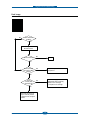
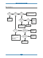
■ Description of DADF JAM type
PAPER EMPTY
SENSOR
FEED
SENSOR
Type
Document Jam
Service Manual
SCAN
SENSOR
Case
All case of DADF Jam
Jam Removal
1. Open DADF open cover
2. Remove jammed paper
OR
1. Open DADF open cover and Lift up DADF middle
cover
2. Remove jammed paper
4-4
Alignment and Troubleshooting
4.1.2.1 Clearing Jams in the DADF
When a document jams while it passes through the DADF, a warning message appears on the display.
NOTE: To prevent document jams, use the document glass for thick, thin or mixed documents.
1. Remove the remaining documents from the DADF.
If the document is jammed in the paper feed area:
a. Open the DADF cover.
c. Close the DADF cover. Then reload the
document into the DADF.
b. Remove the document by gently pulling it out.
Service Manual
4-5
Alignment and Troubleshooting
If the document is jammed in the paper exit area:
a. Open the DADF cover.
c. Remove the document by gently pulling it out.
b. Open the document input tray upwards and
pull the document gently out of the DADF.
d. Close the DADF cover and the document
input tray. Then load the documents back into
the DADF.
Service Manual
4-6
Alignment and Troubleshooting
If the document is jammed in the duplex path:
a. Open the DADF cover.
c. Remove the document by gently pulling it out.
b. Open the DADF inner cover.
d. Close the DADF inner cover and the DADF
cover. Then load the documents back into the
DADF.
Service Manual
4-7
Alignment and Troubleshooting
2. If you cannot see the paper or cannot pull the
jammed paper out, open the document cover.
4. Close the document cover. Then load the
documents back into the DADF.
3. Remove the document from the feed area by
carefully pulling it gently to the right.
4.1.2.2 Clearing Jams in the Paper Tray
When a paper jam occurs, Paper Jam appears on the display. Refer to the table below to locate and clear
the paper jam.
Operator Panel Message
Paper Jam 0
Location of Jam
Go to
Open Tray 1
Paper Feed Jam (tray 1)
Paper Feed Jam (optional tray 2)
“Paper Feed Jam (tray 1)” or
“Paper Feed Jam (optional tray 2)”.
Paper Jam 1
Fuser Area Jam
“Fuser Area Jam”.
Paper Exit Jam
“Paper Exit Jam”.
between the duplex unit and fuser area
“Duplex Jam 0”.
in the duplex unit
“Duplex Jam 1”.
Remove Cartridge
Paper Jam 2
Open Rear Door
Duplex jam 0
Remove paper &
Open/Close Front Door
Duplex jam 1
Open Rear Door
To avoid tearing the paper, pull the jammed paper out gently and slowly. Follow the steps below to clear the
jam.
Service Manual
4-8
Alignment and Troubleshooting
Paper Feed Jam (tray 1)
1. Open and close the front cover. The jammed
paper automatically exits the printer.
3. Remove the paper by gently pulling it straight
out.
If the paper does not exit, go to the next step.
2. Pull the paper tray open.
If you cannot see the paper or the paper does
not move when pulled, check the fuser area.
For more information, see “Fuser Area Jam”.
4. Insert the paper tray into the printer until it snaps
into place.
Printing automatically resumes.
Service Manual
4-9
Alignment and Troubleshooting
Paper Feed Jam (optional tray 2)
1. Pull the optional tray 2 open.
3. Pull the tray 1 half way out.
4. Pull the paper straight up and out.
2. Remove the jammed paper from the printer.
If you cannot see the paper in this area or the
paper does not move when pulled, go to the next
step.
Service Manual
5. Insert the trays back into the printer.
Printing automatically resumes.
4-10
Alignment and Troubleshooting
4.1.2.3 MPF Jam
1. If the paper is not feeding properly, pull the
paper out of the printer.
2. Open and close the front cover to resume
printing.
4.1.2.4 Fuser Area Jam
NOTICE: The fuser area is hot. Take care when removing paper from the printer.
1. Open the front cover and lightly pull the toner
cartridge straight out.
2. Remove the paper by gently pulling it straight
out.
3. Replace the toner cartridge and close the front
cover.
Printing automatically resumes.
Service Manual
4-11
Alignment and Troubleshooting
4.1.2.5 Paper Exit Jam
1. Open and close the front cover. The jammed
paper automatically exits the printer.
4. If you see the jammed paper, push the two blue
pressure levers down and remove the paper.
Skip to step 9.
If the paper does not exit, go to the next step.
2. Gently pull the paper out of the output tray.
If you do not see the paper, go to the next step.
5. Fully open the rear door, as shown.
3. If you cannot see the paper in the output tray or
the paper does not move when pulled, open the
rear door.
Service Manual
4-12
Alignment and Troubleshooting
6. Unfold the duplex guide fully.
8. Pull the jammed paper out.
If the jammed paper does not move when you
pull, push the two blue pressure levers up to
loosen the paper, and then remove it.
7. While pushing the fuser lever to the right, open
the fuser door.
NOTICE: Ensure that to unfold the duplex
guide before opening the fuser door or you may
damage the fuser door.
9. Return the levers, fuser door, and duplex guide
to their original position.
10. Close the rear door.
11. Open and close the front cover.
Printing automatically resumes.
Service Manual
4-13
Alignment and Troubleshooting
4.1.2.6 Duplex Jam
Duplex Jam 0
1. Pull the duplex unit out of the printer.
3. Push the duplex unit to the printer.
2. Remove the jammed paper from the duplex unit.
4. Open and close the front cover.
Printing automatically resumes.
CAUTION: If you do not push the duplex unit
correctly, paper jam may occur.
If the paper does not come out with the duplex
unit, remove the paper from the bottom of the
printer.
Service Manual
4-14
Alignment and Troubleshooting
Duplex Jam 1
3. Pull the jammed paper out.
1. Open the rear door.
2. Unfold the duplex guide fully.
4. Return the duplex guide and close the rear door.
5. Open and close the front cover.
Printing automatically resumes.
Service Manual
4-15
Alignment and Troubleshooting
Tips for Avoiding Paper Jams
By selecting the correct paper types, most paper jams can be avoided. When a paper jam occurs, follow the
steps outlined in “Clearing Jams in the Paper Tray”.
• Follow the procedures in “Loading Print Media in the Paper Tray”. Ensure that the adjustable guides are
correctly positioned.
• Do not overload the paper tray. Ensure that the paper is below the paper capacity mark on the inside wall of
the paper tray.
• Do not remove the paper from the tray while your printer is printing.
• Flex, fan and straighten the paper before loading.
• Do not use creased, damp or curled paper.
• Do not mix paper types in the paper tray.
• Use only recommended print materials. See “Paper Specifications”.
• Ensure that the recommended print side of print materials is facing down in the paper tray and facing up in
the MPF.
• Ensure that the duplex unit is installed correctly.
- Cleaning the DADF Pick-up Roller/ Feed Roller
DADF Pick-up Roller
Service Manual
Feed-Roller
4-16
Alignment and Troubleshooting
4.1.3 Diagnostic Mode
4.1.3.1 Entering/ Exiting Diagnostic Mode
To enter the diagnostic mode, press 1,2,3 number keys simultaneously.
When the password dialog box appears, enter “1934” and press the “OK” button.
To exit the diagnostic mode, press the home button at the left upper corner of the display.
When exit the diagnostic mode, a popup window shall display.
Selecting “Yes” in “Reboot Copier “will reboot the set.
Service Manual
4-17
Alignment and Troubleshooting
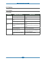
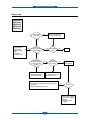
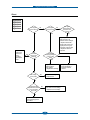
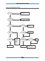
4.1.3.2 Diagnostic Mode Menu Tree
When entering the diagnostic mode, you can see the main window of diagnostic as shown below.
Disabled
In all diagnostic
windows
There are 2 contents. They are “Information” and “Test Routines”.
Each item will have several sub items and they will be listed in below table.
Depth1
Depth2
General
Depth3
Service Tag
Network IP Address
Set Version
Software Version
Information
Main Controller
User Interface
Network Controller
Protocol
Report
Configuration
Error Information
Supplies Information
Copier
NVM Read/Write
Test Routine
NVM Read/ Write
Test Routine
Fax
Test Routine
Protocol Report
Print Test Pattern
Other
Shading Test
Memory Clear
Service Manual
4-18
Alignment and Troubleshooting
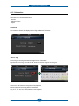
4.1.3.3 Information
Information menu will have below items
- General
- Software Version
- Report
a) General
When selecting General, OP displays Service Tag and Network IP Address.
- Service Tag
Service Tag will be string and maximum length will be 7 characters.
Right side of Service Tag, there will be “Edit” button and service engineer can change it.
If user touch “Edit” button then keyboard will be displayed.
On the keyboard user can change the Service Tag.
Maximum length of Service tag will be 7 characters.
Only ‘A~Z’, ‘a~z’ and ‘0~9’ will be allowed on the keyboard
Service Manual
4-19
Alignment and Troubleshooting
b) Software Version
This menu displays all the version of the software installed in the system in detail. The following software
version will be shown in the menu.
- Set Version
- Main Controller
- User Interface
- Network Controller
C) Report
This menu displays reports which that can be printed from the system. The following reports will be available
to print.
- Set Version
- Main Controller
- User Interface
- Network Controller
Service Manual
4-20
Alignment and Troubleshooting
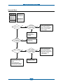
4.1.3.4 Test Routine
Test Routine has items to check machine functionalities.
This menu has below sub-items.
- Copier
- Fax
- Other
a) Copier
This menu has below sub-items.
- NVM Read/Write
- Test Routine
Service Manual
4-21
Alignment and Troubleshooting
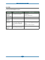
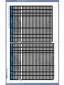
- NVM Read/Write
NVM Name
Chain &
Link
Current
Value
Each item of Copier NVM list consists of “Chain & Link”, “NVM Name” and Current Value.
If user touches one item then
1. Selected item is not editable then notification message will be display on LCD for 2 seconds
“Selected item is not editable.”
2. Selected item is editable then it will move to NVM Edit window.
1
3
4
2
5
Service Manual
4-22
Alignment and Troubleshooting
Name of item : it shall include chain & link
Default Value : It will display the default value of current item. If user touches “Apply Default” button
then default value will be applied to current value on editing box.
Range : this area will display the range of selected item with minimum and maximum value.
Plus/Minus sign : If input value of selected item supports both positive and negative number then this
member will be activated and user can select positive and negative.
Below icon will be displayed according to input range
Only positive number allowed :
Only negative number allowed :
Both Positive and Negative number allowed :
User can change positive to negative and negative to positive by touching this button
Editing box: User can increase and decrease the value by touching
User can input the value by numeric hard buttons (3*4 keys) also.
If user touches
button then window will move to upper level and new value will be applied to the
system. But new value is out of range, it will not move to upper level but display error pop-up window as
below. When user closes pop-up, it will retain previous value.
Service Manual
4-23
Alignment and Troubleshooting
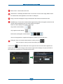
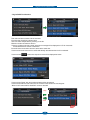
- Engine/DADF Test Routines
Test routine window consists of list of test items.
Each item has Chain/Link and item name.
User can select multiple items by touching on the list.
Maximum number of selection will be 3.
If user try to select more than 3 items, below error message will be displayed on LCD for 2 seconds.
“Exceeded maximum number of selections”
But some items are exclusive and can’t select at the same time.
If user touches some items but it is conflict with already selected item then it will not selected.
If user touches
button then drop down menu will be displayed as below.
If user touches “Reset” then all the selected items will be de-selected.
If user touches “Move to test” button, then it will move to the window for executing test.
“Move to test” button shall be disabled if no item is selected.
Stop
Start
Current
Value
Service Manual
4-24
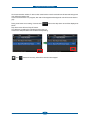
Alignment and Troubleshooting
On the test execution window, if user touches some item then test for touched item will start and background
color will be changed to blue.
If user touch item which is on progress, then test will be stopped and background color will be revert back to
gray.
button then drop down menu will be displayed as
During some items are on testing, if user touches
below.
Drop down menu will have “Stop All” button.
If no items are on testing, then this button will be gray out.
If user touch “Stop All” button then all items will stop testing.
and
Service Manual
button will work only when all the test items are stopped.
4-25
Alignment and Troubleshooting
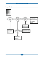
b) Fax
This menu has below sub-items.
- NVM Read/Write
- Test Routine
- Protocol Report
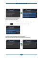
- NVM Read/Write
NVM
Name
Chain &
Link
Current
Value
Each item of fax NVM list is consist of “Chain & Link”, “NVM Name” and Current Value.
If user touch one item then it will move to edit window as below
1
3
4
2
Service Manual
5
4-26
Alignment and Troubleshooting
Name of item : it shall include chain & link
Default Value : It will display the default value of current item. If user touches “Apply Default” button
then default value will be applied to current value on editing box.
Range : this area will display the range of selected item with minimum and maximum value.
Plus/Minus sign : If input value of selected item supports both positive and negative number then this
member will be activated and user can select positive and negative.
Below icon will be displayed according to input range
Only positive number allowed :
Only negative number allowed :
Both Positive and Negative number allowed :
User can change positive to negative and negative to positive by touching this button
Editing box: User can increase and decrease the value by touching
User can input the value by numeric hard buttons (3*4 keys) also.
If user touches
button then window will move to upper level and new value will be applied to the
system. But new value is out of range, it will not move to upper level but display error pop-up window as
below. When user closes pop-up, it will retain previous value.
Service Manual
4-27
Alignment and Troubleshooting
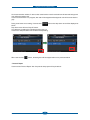
- Fax Routines
Test routine window consists of list of test items.
Each item has Chain/Link and item name.
User can select multiple items by touching on the list.
But some items are exclusive and can’t select at the same time.
If user touch some items but it is conflict with already selected item then it will not selected.
If user touches
button then drop down menu will be displayed as below.
If user touch “Reset” then all the selected items will be de-selected.
If user touch “Move to test” button, then it will move to the window for executing test.
“Move to test” button shall be disabled if no item is selected.
Stop
Start
Service Manual
4-28
Alignment and Troubleshooting
On the test execution window, if user touches some item then test for touched item will start and background
color will be changed to blue.
If user touch item which is on progress, then test will be stopped and background color will be revert back to
gray.
button then drop down menu will be displayed as
During some items are on testing, if user touches
below.
Drop down menu will have “Stop All” button.
If no items are on testing, then this button will be gray out.
If user touch “Stop All” button then all items will stop testing.
When user touches
button, all testing item will be stopped and move to previous window.
- Protocol Report
If user touches “Protocol Report” then fax protocol dump report will be printed out.
Service Manual
4-29
Alignment and Troubleshooting
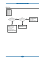
c) Other
Other menu is consist of below sub items
- Print Test Pattern
- Shading Test
- Memory Clear
- Printer Setup
- Print Test Pattern
1
2
3
User can select the one among 7 test patterns. By default, Test Pattern number shall be 1.
User shall select paper source by selecting tray.
• Tray1
• Tray2
• MPF
User shall select duplex printing option by selecting on Duplex Menu
• Off
• 2Sided
If user press “Start” button then the test pattern will be printed.
Service Manual
4-30
Alignment and Troubleshooting
- Shading Test
User can the shading test to check quality of scanned images, especially defect in optical devices, including
lens, mirror, lamp, and etc, are suspected.
Press Start button beside “Share and Print report“ to see if the current shading value is correct.
Mono, red, green, blue gray shading values will be shown on the printed report.
When the previous shading value is needed, press Start button beside “Print Last Shade Report”.
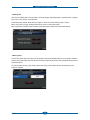
- Memory Clear
This function resets the main memory of the system to the factory default setting. It can be used to reset the
system to the initial value when the product is functioning abnormally. All the user configured values return to
the default values.
To clear the main memory, users need to select the country of the system locates, and rebooting of the
system is required.
Service Manual
4-31
Alignment and Troubleshooting
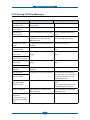
- Printer Setup
This menu has the Altitude Adjustment menu as sub menu.
The print quality is affected by atmospheric pressure, which is determined by the height of the machine
above sea level. The following information will guide you on how to set your machine to the best print quality
or best quality of print. Before you set the altitude value, find the altitude where you are using the machine.
Service Manual
4-32
Alignment and Troubleshooting
4.1.4 Abnormal Image Printing and Defective Roller
If abnormal image prints periodically, check the parts shown below.
6
2
3
4
1
7
5
1
2
3
4
5
6
7
OPC Drum
Charge Roller
Supply Roller
Transfer Roller
Heat Roller
Pressure Roller
Developing Roller
No
Roller
Abnormal image period
Kind of abnormal image
1
OPC Drum
75.5mm
White spot, Block spot
2
Charge Roller
37.7mm
Black spot
3
Supply Roller
44.9mm
Horizontal density band
4
Develop Roller
35.2mm
Horizontal density band
5
Transfer Roller
47.1mm
Black side contamination/transfer fault
6
Heat Roller
77.8mm
Black spot and fuser ghost
7
Pressure Roller
75.4mm
Black side contamination
Service Manual
4-33
Alignment and Troubleshooting
4.2 Troubleshooting
4.2.1 Procedure of Checking the Symptoms
Before attempting to repair the printer first obtain a detailed description of the problem from the
customer.
Power On
OP Panel
ON?
- No Power
- Power Module error
- Main PBA error
- LCD Panel error
Ready or
Power save
Indicate
Error Massage
Test Print
printing
Quality is
Nomal?
Refer to "Solution
of Print Quality"
END
Service Manual
4-34
Refer to
4.2.2 Clearing
LCD Error Messages
Alignment and Troubleshooting
4.2.2 Clearing LCD Error Messages
Display message
Meaning
Suggested solutions
Rear Cover is open
Close Rear Cover.
The rear door was opened while
duplex printing
Close the rear door.
Data Read Fail
Check USB key
Time expired while reading data.
Try again.
Data Write Fail
Check USB key
Storing to the USB memory key failed. Check the available USB memory
space.
Device is not supported
Non USB mass storage device, such
as USB mouse, is connected with
USB memory port
Remove the non USB mass storage
device from USB memory port.
Document Jam Check
Feeder
The loaded document has jammed in
the DADF.
Clear the document jam.
Toner Door is open
Close Toner Door
The front cover is not securely latched. Close the cover until it locks into
place.
Duplex jam 0
Check Inside
Paper has jammed during duplex
printing.
Clear the jam. See "Clearing Paper
Jams"
Paper has jammed during duplex
printing.
Clear the jam. See "Clearing Paper
Jams"
File format is not
supported.
The selected file format is not
supported.
Enter the correct item again.
Fuser Door Open
The fuser door is not securely latched. Open the rear door and close the
fuser door until it locks into place. For
the location of the fuser door, see
“Clearing Paper Jams”.
Remove paper
& Open/Close Front Door
Duplex jam 1
Check Inside
Open Rear Door
Open Rear Door
Close Fuser Door
Fuser Error
Fuser Not Installed
Check Rear Door
There is a problem in the fuser unit.
Unplug the power cord and plug it
back in.
If the problem persists, refer to the
troubleshooting for Fuser Error.
Hub is not supported
USB hub device is connected with
USB memory port.
Remove the USB hub device from
USB memory port.
In Idle State : [yyy]
Empty/Open
In Printing State : [yyy]
Empty/Open Load [zzz]
[xxx]
The paper in the paper tray has run
out.
Load paper in the paper tray.
Service Manual
4-35
Alignment and Troubleshooting
Display message
Meaning
Suggested solutions
Invalid Cartridge
Cartridge is not valid for
this machine
The toner cartridge you have installed
is not for your printer.
Install a Dell-genuine toner cartridge,
designed for your printer.
IP Conflict
IP address conflict.
The network IP address you have set
is being used by someone else.
Check the IP address and reset it if
necessary
Fax Job is completed with The received fax number is the
error Incompatiable
number stored
Change the Junk Fax Setup option.
Job cannot be accepted
because line is busy
The receiving party did not answer or
the line is already engaged.
Try again after a few minutes.
Line Error
Your printer cannot connect with a
remote printer or has lost contact
because of a problem with the phone
line.
OR
No dial tone sounds
- Try again. If the problem persists,
please wait for an hour or try a
different phone line if possible and
then try to connect again.
- Turn the ECM mode on. See ECM
Mode.
- Check that the phone line is
connected properly.
- Check that the phone socket in the
wall is working by plugging in another
phone.
Check Fax Line
Fax Job is completed with The printer has a communication
error : Line Error
problem.
Ask the sender to try again.
Low Heat Error Power
Cycle
There is a problem in the fuser unit.
Unplug the power cord and plug it
back in.
If the problem persists, refer to the
troubleshooting for Fuser Error.
LSU Hsync Error Power
Cycle
A problem has occurred in the Laser
Scanning
1. Unplug the power cord and plug it
back in.
2. Check if the connection between
the LSU and the main board is correct.
3. If the problem persists, replace the
LSU.
Email Job is completed
with error : Mail excced
server support
The mail size is larger than the
supported size by SMTP server.
Divide your mail or reduce the
resolution.
Email Job is completed
with error : Mail too large
Single page data exceeds the
configured mail size.
Reduce the resolution and try again.
Memory Full
The memory is full.
Delete unnecessary documents,
retransmit after more memory
becomes available.
Service Manual
4-36
Alignment and Troubleshooting
Display message
Meaning
Fax Job is completed with The memory is full.
error : Memory Full
Suggested solutions
- Split the transmission into more than
one operation.
- Print received faxes.
- Cancel reserved fax in the Priority
Fax feature.
MPF Empty Load [zzz]
[xxx]
Press √ Continue
The paper in the MPF has run out.
Load paper in the MPF.
Network Cable Error
Network cable is
disconnected.
The network cable is disconnected.
Connect the network cable.
Network Card Error
Network card is not
installed.
The network card is not installed.
Install the network card.
Fax Job is completed with The remote fax machine has not
Try again. Verify the number to ensure
error : No Answer
answered after several redial attempts. that a fax can be received.
No Toner Cartridge
Toner Cartridge is not
installed
The toner cartridge is not installed.
If the toner cartridge is not installed
in the machine, install the toner
cartridge.
Over Heat Error Power
Cycle
There is a problem in the fuser unit.
Unplug the power cord and plug it
back in.
If the problem persists, refer to the
troubleshooting for Fuser Error.
Paper Jam 0 Open Front
Door
Open Tray 1
Remove paper & Open/
Close Front Door
Paper has jammed in the feeding area Clear the jam. See "Clearing Paper
of the paper tray.
Jams"
Paper Jam 1
Remove Cartridge
Paper has jammed in the fuser area.
Clear the jam. See "Clearing Paper
Jams"
Paper Jam 2 Check
Inside
Open Rear Door
Paper has jammed in the paper exit
area.
Clear the jam. See "Clearing Paper
Jams"
Scanner locked Unlock
scanner
Pull blue latch forward &
Press >
The scanner module is locked.
Unlock the scanner and press Cancel
(X).
Self Diagnostic...
Please wait
The engine in your printer is checking
some problems detected.
Please wait a few minutes.
Email Job is completed
with error : DNS Error
There is a problem in DNS.
Configure the DNS setting.
Email Job is completed
with error : Pop3 Error
There is a problem in POP3.
Configure the POP3 setting.
Service Manual
4-37
Alignment and Troubleshooting
Display message
Meaning
Suggested solutions
Email Job is completed
with error : Send Failed
There is a problem in SMTP.
Change to the available server.
Email Job is completed
with error : Authentication
Failure
There is a problem in SMTP
authentication.
Configure the authentication setting.
Email Job is completed
with error : Network Error
There is a problem on the network
interface card.
Configure your network interface card
correctly.
Email Job is completed
with error : Server
Connection Error
Connection with the SMPT server
failed.
Check that the network cable is
connected properly.
OR Contact your SMPT server
administrator.
[yyy] is empty or open
There is no paper in the tray.
Load paper or close [yyy].
Load paper in the tray.
Toner Almost Empty
Replace Toner
The toner cartridge is empty.
Replace the toner cartridge with a new
one.
Toner Low
Order New Toner
The toner cartridge is almost empty.
Take out the toner cartridge and
thoroughly
shake it. By doing this, you can
temporarily
reestablish printing operations.
OR
Replace the toner cartridge with a new
one for the best print quality.
Waiting Line
The machine is waiting for the
programmed interval to automatically
redial.
Please wait a few minutes.
Service Manual
4-38
Alignment and Troubleshooting
4.2.3 Solution
4.3.2.1 Scanner
4.3.2.1(a)COPY
PROBLEM
White copy
Black copy
Defective image
quality
Abnormal noise
Service Manual
ITEMS TO BE CHECKED
HOW TO SOLVE
• Check the Scan-Cover open.
• Room light can transit a thin original.
• Check shading profile.
• Execute the shading test in the diagnostic
mode.
• Check the CCD problem in Main
PBA.
• Check the CCD harness contact.
• Check shading profile.
• Execute the shading test in the diagnostic
mode.
• Execute the shading test in the diagnostic
• Check shading profile.
• Check the gap between original and mode.
• The gap above 0.5mm can cause a blurred
scanner.
image.
• Check printing quality.
• See “Print” troubleshooting.
• Check the Scanner Motor and any
mechanical disturbance.
• Check the right position of the Scanner Motor,
and check the any mechanical disturbance in
the CCD carriaging part.
• Check the Motor Driver in Driver
PBA.
• If any driver is defective, replace it.
4-39
Alignment and Troubleshooting
4.3.2.1(b) PC-Scan
PROBLEM
Scanning Error
Defective image
Quality
Abnormal noise
Service Manual
ITEMS TO BE CHECKED
HOW TO SOLVE
• Check the printer cable installed.
• Check correct installation, and use standard
USB cable.
• Check how TWAIN driver is
installed.
• Remove any other scanner driver.
• Reboot after reinstallation of the TWAIN driver.
• Check the USB signal level.
• If USB signal level is defective, replace Main
PBA.
• Execute the shading test in the diagnostic
• Check shading profile.
• Check the gap between original and mode.
• The gap above 0.5mm can cause a blurred
scanner glass.
image.
• Check printing quality.
• See “Print” troubleshooting.
• Check the Scanner Motor and any
mechanical disturbance.
• Check the right position of the Scanner Motor,
and check the any mechanical disturbance in
the CCD carriaging part.
• Check the Motor Driver in Driver
PBA.
• If any driver is defective, replace it.
4-40
Alignment and Troubleshooting
4.3.2.2 FAX
4.3.2.2(a) FAX/TELEPHONE Precautions
PROBLEM
ITEMS TO BE CHECKED
HOW TO SOLVE
TEL LINE
CANNOT BE
ENGAGED
(NO DIAL TONE)
• When you press “ OHD” key:
a) Check line cord connection.
a) insert it correctly into the connection jack
called “line”.
b) Replace defective parts.
Cannot MF dial
• Check MAIN-LIU harness.
• Replace defective parts.
MF dial is
possible but
not DP dial.
• Check the main PBA.
• Replace main PBA.
Defective fax
transmission
• Check MAIN LIU harness.
• Check ‘hook off’ : Refer to ‘TEL
LINE CANNOT BE ENGAGED’
above.
• Replace defective parts.
• Refer to ‘TEL LINE CANNOT BE ENGAGED’
above.
• Replace main PBA, if abnormal.
Defective
automatic fax
reception
• Is the ring checked?
• Refer to ‘Defective Transmission.’
• Refer to ‘Defective Transmission’.
Service Manual
4-41
Alignment and Troubleshooting
No Image
Digital Printer
Digital Printer
Digital Printer
Digital Printer
Digital Printer
No image?
A on
next page
NO
YES
Self test
pattern prints?
YES
Check connection to
computer or replace
controller
NO
Self testing
is possible ?
NO
Retest after replacing the
connector or controller board
YES
Take out the cartridge
and prepare the tester
for electronic connection
Is the OPC
terminal of machine
is well-connected
to Frame?
NO
Repair or replace the GND
terminal
YES
Does the
video data line to
LSU transit to High/Low
when printing?
NO
YES
The mirror in LSU might be
misplaced so the light path to the
OPC deviates ->Repair or replace
LSU or remove any defective
matters in the machine
Service Manual
4-42
Check the path between
Main board
and HVPS. Repair or replace
the defective component
or board
Alignment and Troubleshooting
A
Transfer
voltage OK? (on the
transfer roller
shaft)
NO
YES
Are the
connection terminal
and connection
correct?
NO
Repair or replace terminal
YES
Replace HVPS or repair defective component
Developing
(-450V) and supplying
(-600V) voltage
are OK?
NO
Is the connection
terminal OK?
NO
Repair or replace terminal
YES
YES
Replace HVPS or repair
defective component
Does the
counter indicate over
the toner's guaranty
life
YES
NO
Transfer roller might be out of its location
-> Locate the roller into its place
This could occurs when he power of LSU is low or
the density is low due to the obstacles on the window
-> Replace LSU or clean the window
Replace the toner cartridge
Service Manual
4-43
Alignment and Troubleshooting
All Black
Digital Printer
Digital Printer
Digital Printer
Digital Printer
Digital Printer
All black in
printing area?
NO
YES
Does the
video data line to LSU
transit to High/Low when
printing?
NO
YES
Replace LSU
Is charge
voltage supplied
from HVPS?
NO
Repair or replace HVPS
YES
Is the
Hsync signal received
in LSU?
NO
Replace LSU
YES
Charge part's contact
is bad -> Repair or
replace the drum cartridge
Service Manual
4-44
Check the path among video
controller, engine board,
HVPS, LSU for the shortage
or open -> Repair or replace
the boards
Alignment and Troubleshooting
Vertical White Line (Band)
Digital Printer
Digital Printer
Digital Printer
Digital Printer
Digital Printer
White line
missing definitely?
NO
YES
Dirt of dust stuck onto the
window of internal lens of LSU
-> Clean it or replace LSU
Preventive obstacles through
the path between OPC of
toner cartridge and LSU prevent the
path -> Remove the obstacles
Service Manual
Check if the
printout is still has the
NO
same problem even right after
passed through the
transfer roller
YES
Toner material might be stuck to
blade in the developer inside and it
prevents toner supply -> Replace
the toner cartridge
Check both if the toner cartridge's
counter is over its guaranty and
amount of the toner material
-> Replace the toner cartridge
4-45
The ribs in fuser or toner on the
roller may invoke the image
problem -> Replace the fuser
cover or the defective part
The image is originally black or the
black part is far close to the top
-> Use the pattern which has the
image below bigger than 10mm
from the top
Alignment and Troubleshooting
Dark Image
Digital Printer
Digital Printer
Digital Printer
Digital Printer
Digital Printer
NO
Dark selected
via RCP?
YES
Change to
Normal and test
NO
END
Same at Normal?
YES
Works correctly
with -450V of Bias
voltage?
NO
Repair or replace the defective
component
YES
Works
correctly after
replaced LSU?
Toner over supply due to the
adjustment fault of metering
blade in toner cartridge
-> Replace toner cartridge
NO
YES
The power of LSU is set
high or internal problem
-> Replace LSU or adjust
volume
Service Manual
4-46
Alignment and Troubleshooting
Barkground
Digital Printer
Digital Printer
Digital Printer
Digital Printer
Digital Printer
Recommended
paper used?
NO
Print 20 to 30 pages using
the recommended paper
YES
- Adjust voltage or
replace HVPS
- Repair or replace
after
checking the
terminals' contacts
NO
Transfer,
charge and developing
voltage are OK?
YES
Same problem
occurs?
NO
END
NO
Replace the
toner cartridge
YES
Operating/
storage atmosphere is
too high temperature
/humidity?
NO
YES
YES
Solve the problem under
the recommended condition
(10-32 degree Centigrade)
Dirty or
dust around the
charge roller?
Clean the charge roller
or replace step-up device
/terminal after check
Check Terminals or contacts and "transfer roller springs"
are misplaced
-> Repair or replace transfer roller etc.
NO
Work OK?
YES
Internal blade or supplying
part of the toner cartridge
is defective
-> Replace the toner
cartridge
Service Manual
4-47
Alignment and Troubleshooting
Ghost
Digital
Digital Printer
Printer
Digital
Digital Printer
Printer
Digital
Digital Printer
Printer
Digital
Printer
Digital Printer
Digital
Digital Printer
Printer
Is it regular
interval of 94.3mm?
Is it regular
interval of 54.3mm?
NO
YES
Is it regular
interval of 56.6mm?
(as transfer roller
interval)
NO
YES
YES
A specific part of the transfer
roller has ruined or its
resistance value is changed
-> Replace transfer roller
Check HVPS
contacts and
HVPS's selfoutput
-> If failed,
repair/replace
HVPS
Transfer roller cannot force
regularly due to the gears
eccentricity of transfer roller
-> Replace the defective
component
NO
Developing
/supplying voltage
normal? (-450V/
-600V)
Transfer
voltage is set to
standard?
YES
YES
Irregularity of NIP
between rollers in
toner cartridge
-> Replace toner cartridge
Bias voltage
is OK? (-450V)
NO
NO
- Repair or replace HVPS
- Check and Repair or
replace the terminal
contacts
Adjust the Bias voltage
or replace HVPS
YES
Operating/storage
temperature is too low or
not recommended
paper used?
NO
There may be a problem in toner
layer control in toner cartridge
-> Replace the toner cartridge
YES
Use the machine with
recommended paper and
at condition
Service Manual
4-48
Alignment and Troubleshooting
Black Spot
Digital Printer
Digital Printer
Digital Printer
Digital Printer
Digital Printer
Is it regular
interval of 38.3mm?
NO
YES
The problem occured
since the obstacles
stuck to charge roller
-> Clean the Charge Roller
and then reprint.
Service Manual
When taking
NO
out the toner cartridge,
toner leaks?
Bad image
removes by
scratching?
YES
YES
Toner leaks and much
toner material dropped
onto the paper ->
Replace the toner cartridge
4-49
Check toner is stuck onto
the P/R or H/R in fuser
-> Clean it or replace
NO
The problem
randomly occurred
due to the toner
fallen -> Clean the
machine
Alignment and Troubleshooting
Horzontal Band
Digital Printer
Digital Printer
Digital Printer
Digital Printer
Digital Printer
Digital Printer
Digital Printer
Digital Printer
Digital Printer
Digital Printer
Black band?
NO
Black band
is far about 94.3mm from
white band?
NO
YES
The OPC is damaged under the
direct sunlight for around 5
minutes -> If the same problem
persists in 10 hours, replace
the drum cartridge
Problem of internal
contacts in OPC
-> Replace the drum
cartridge
The black
band has regular
interval?
NO
This occurs when no
Hsync/ at LSU
-> Replace LSU
YES
94.3mm interval?
NO
YES
The OPC is damaged due to
the irregular transfer voltage
of HVPS
-> Repair/replace HVPS
-> If the same problem persists,
replace the drum cartridge
Service Manual
Does it appear
at every 83.6mm at
specific place?
YES
Heat roller is ruined
-> Replace the roller
4-50
NO
Problems of terminal contact,
transfer voltage supplying,
and transfer roller's due to the
charge roller is ruined (38.3mm)
-> Repair/replace HVPS,
drum cartridge
Alignment and Troubleshooting
Irregular Density
OK after
taking out and
rocking the toner
cartridge?
YES
NO
When gray
pattern printing,
irregular density
persists?
transfer/
charge/developing
voltage drops while
printing?
NO
YES
NO
YES
Check high voltage
output and repair/
replace terminals, HVPS
It is over the guaranty
life of toner cartridge
(Check the counter
and replace it)
Bad images
NO
around the no image
area?
Irregularity of toner
supply from the toner cartridge
-> Replace the toner cartridge
YES
Light distortion due to
the mirror ruined or
LSU's diffused reflection
-> Replace LSU
Service Manual
4-51
Defective agitator in
the toner supplying part
of the toner cartridge
->Replace the toner cartridge
Check if the 'guide deve
spring' works OK and
repair/repalce
Alignment and Troubleshooting
White Spot
Digital Printer
Digital Printer
Digital Printer
Digital Printer
Digital Printer
Is it regular
interval of 94.3mm?
NO
YES
Obstacles stuck on OPC's
surface
-> Clean the OPC and
machine or replace
toner cartridge
Transfer
voltage is normal?
YES
D/R in the toner cartridge
unit has the defect
-> Replace the toner cartridge
When putting in/out the
drum cartridge, scratch is made
-> Replace the drum cartridge
Service Manual
NO
4-52
Too high voltage supplied
due to the setting error of
transfer voltage
-> Adjust/replace HVPS
Alignment and Troubleshooting
Trembling at the End When OHP Printing
Recommended
OHP film used?
NO
Use the recommended film
YES
Inserted over
than 10 films into
the MPF?
NO
When OHP
printing, does the fan
temporarily stops
and revolves?
YES
When multi-page OHP printng,
less than 10 films are
guranteed. (Reduce the
number of films and re-insert
after paper check LED if off)
Service Manual
YES
Other parts are touching the
fan and prevents it from
revolution
-> Check and repair
4-53
NO
Use the recommended film
Alignment and Troubleshooting
Poor Fusing Grade
After printing
NO
completed, any error
related fuser?
YES
Both ends
of thermostat
open?
The machine
placed under the
severe low tempera
ture for a long
time?
NO
While printing,
NO
the voltage of pin 60
of U36 (CPU) on Main
PBA is 2.1V
- 2.6V?
YES
NO
Thermistor's
contact is OK?
NO
YES
YES
Re-assemble
thermistor
Place the machine
at normal
temperature and
re-test
YES
Replace thermostat
and re-test
Open the top
cover. When black
printing, is the fuser NIP
width is 3.03.5mm?
YES
Replace the control
component on Main
PBA
Check any contact
problem in thermistor
and repair
Service Manual
The paper used is too
thick or contains too
much cotton in it
-> Re-test with the
recommended paper
4-54
NO
Check if the hardness of
P/R, and spring force is OK?
(hardness: 24 degree,
spring's force: 3 Kg)
Alignment and Troubleshooting
4.3.2.4 Malfunction
Error Status
Check
Solution
Cover open
1. When close Side cover, check the
lever is pressed
2. Micro switch’s contact
3. CPU and related circuit
1. Open Side cover and press the lever with pen.
If Controller detects cover close, there is some
mechanical trouble in Side cover and lever’s
assembly. If not so there is electrical problem.
Jam 0
Check where Jam 0 happens
1. Paper is not picked up
2. Paper is located in feed sensor
3. Happened when inserting specific
papers such as envelope into the
MPF (Multipurpose Paper Feeder)?
4. Happened when inserting specific
papers such as envelope into the
Manual Feeder?
5. Is the Stacker Extender is folded
out?
6. Does not the Guide Adjust distort the
papers
1. Check whether solenoid is working or not by using
Engine test mode
2. Check feed sensor malfunction.
3. Re-try inserting a fewer papers.
• fan the papers and align
• take out the loaded papers and insert them
reverse direction
4. Take out the loaded papers and insert them
reverse direction
• inserted papers as recommended for Manual
Feeding?
• When loading, tap the papers until paper detect
sensor senses loading
5. When using long papers, use the Stacker
Extender
6. Adjust Guide to fit the paper width
Jam 1
Paper is stopped in just after of fuser
unit.
1. It is mostly resulted from double feeding.
Check paper is well stocked in feeder.
2. Check feed actuator position and actuator’s
operating. There may be stiff movind or double
reflection. If not so, check the operation of feed
sensor by Engine test mode.
3. Check exit lever operation. Remore jam and
check actuator moving by hand. If actuator is
too stiff, paper is wrapped around the heat roller.
Remove obstacles or replace.
Jam 2
Check where Jam 2 happens
1. Paper is curled and cannot exit.
2. Paper is curled in the exit cover?
1. Remove paper using pinset or some tool and
watch if separate claws have any troble.
Clean around fuser.
2. Check locking works wells. Watch whether the
ribs of exit cover hace any burr or resisitive edge.
If they do, remove obstacles or replace.
Jam 2 at facedown
tray
1. Then paper is not drawn in because 1. Load recommended quantity of papers
of the stack of papers in the Out tray. 2. Open the Cover Front and check whether roller or
spring, which are related to paper out, is not out
2. Does it curl while coming out?
of position. If so, re-locate or replace.
Service Manual
4-55
Alignment and Troubleshooting
Error Status
Check
Solution
Clutch error
1. Check the spring of solenoid
2. Check the armature assembly/
cushion
3. Electrical check
1. Check whether the spring is expanded or not.
2. Check armature is well installed. It may be
unstable assemble.
3. Remove the Main PBA.
High voltage
error
1. Check the terminal output voltage
2. Check HVPS
1. Remove the Toner cartridge and open the cover
and press cover open switch lever and measure
the voltage with high voltage probe and sending
printing data. If the voltage is normal, change the
toner cartridge.
2. Disassemble the left side cover, and check HV of
the solder side of HVPS and change it.
Feeding
obstacles
Does the Plate-knockup prevent the
paper loading?
MPF :
Turn the power off and on. Open and close the Side
cover to return to the original state.
Cassette :
Adjust Guide to fit the paper width.
Skew
Is the Guide adjust set to the paper
width?
Fit the paper width using the Guide adjust.
Stacking
1. Took out the Stacker extender to
support long papers?
2. Stacked too many papers more than
Stacker can hold?
1. Use extender as per the paper length.
2. The Face-up stacker normally can hold 100 pages
when using 75g/m2, however, stacking capacity
can be lowered depending on the type of papers.
Engine Error
Check CBF Harness_CN7.(Main PBA
to LSU)
Refer to troubleshooring “ENGINE ERROR”.
Document Jam
Document is not picked up(in ADF).
1. Check document is well stocked in ADF.
2. Check whether document was been fastened
together by staple or clip.
3. Load recommended quantity of papers.
Document is stopped after it has fed
into the ADF.
1. Check whether the Reg. sensor is working or not.
2. Check whether the Feed Roller is working or not.
Does it curl while coming out?
1. Check the Open Cover whether there are bosses.
2. Check the ADF ass’y is well assemble.
Service Manual
4-56
Alignment and Troubleshooting
No Power (LCD NO display LED Off)
Plug in the
power cord?
NO
Check the voltage first and plug
the power cord
YES
The power
NO
voltage supplying is
the same as
rating?
Supply the power as the rating
YES
The fan
revolves when
powered on?
Connections
NO
on board are OK?
NO
YES
YES
LEDs blink
once when
powered on?
NO
Fuse of SMPS
if open?
YES
Repair/replace the
board
Service Manual
NO
Replace the fuse
YES
YES
Shortage on
the OPE panel
board?
Re-connect firmly
and re-test
NO
The connection
error between
controller board
and panel board
or malfunction
of boards.
-> Replace the
boards
Shortage
between 5V and
GND, or between
24V and
GND?
YES
Remove the shortage
or replace the board
4-57
NO
Toner cartridge
is in the set?
NO
YES
Detect failure due to the
board which detects side
cover open or switch error
-> Replace the board or switch
Put in the
cartridge
Alignment and Troubleshooting
Fuser Error
Measure the resistance at the both ends
of AC(Con no.2 of the SMPS board)
Line with covers open
Less than 10W?
NO
Thermostat is open due to the heat etc.
-> Replace the thermostat
YES
Remove the covers
Check CN26 of the main board.
Is the conector inserted
right ways?
NO
Re-assemble the connector.
YES
Check CN23 of the main board.
Is the conector inserted
right ways?
NO
Replace the main board.
Fuser Error eliminated?
YES
END
Service Manual
Re-assemble the connector.
4-58
Alignment and Troubleshooting
Paper Jam (Mis-Feeding)
Sounds the
solenoid on when starts
print?
NO
The solenoid defected
-> Replace it
YES
Does the
paper move?
The Main PBA board defected
-> Replace boards
NO
The pick-up unit is
assembled wrong
-> Re-assemble or replace
the unit
YES
Does the
paper move more than NO
100mm?
Too many
papers in the
feeder?
YES
Feeder
sensor is assembled
reverse?
YES
NO
The sensor and
Main PBA defected
-> Repair/replace
Reduce the amount
and re-test
YES
Switch them
Paper guides
fit the paper width?
NO
Take out the paper
and re-insert
YES
Paper end curled?
NO
YES
YES
<Recommendation>
Use the MPF for the thick
paper such as envelope
and cardstock
Use the recommended
and quality paper
Service Manual
Does the
extender pulled out?
4-59
NO
Pull out the
extender
Alignment and Troubleshooting
Paper Jam (Jam 1)
Paper
NO
stopped before
the OPC?
Paper
NO
stopped before
the fuser?
YES
YES
The
actuator of
NO
paper exit sensor
works OK?
Check the actuator exists and its
operation and around the Main PBA
-> Replace
YES
Check the LSU and
if it has the defect
replace it
Is the paper
rolled around the
presseure
roller?
Feeds
NO
multiple pages?
NO
YES
YES
Remove the fuser, remove
the paper and replace the
pressure roller, if necessary
Severe skew
when feeding?
Remove any factors
The paper
came out through
between fuser and
developer?
NO
YES
NO
Check the input path
to the fuser (such as
mis-assembly)
YES
Too thin
or sensitive paper to
static electricity?
Adjust the paper guides to fit the
paper width
The force of springs pressing the
developer is weak
-> Check guide-DEVE
YES
Use the recommended
paper
Service Manual
Check the roller
and ribs of fuser
are in place, and
remove burrs, if
any
-> Remove the
factors of jam
4-60
NO
Check guide transfer
is grounded Check
the shutter prevents
feeding
Service Manual
5-1
3P
18P
4P
2P
4P
3P
SCF (Option)
WNIC (Option)
MODEM
(Silab Smart DAA)
USB HUB
(USB2415)
8P (DIN 8P)
40P
12P
MP_EMPTY
5P
USB 2.0
(ISP1761)
EEPROM
(M24512)
RTC Clock
(32.768MHz)
RTC battery
(CR2032)
DDR2 SDRAM
(SODIMM/Option)
256MB
DDR2 SDRAM
(SODIMM/BASE)
256MB
MAIN PBA
USB2.0 Device
USB2.0 Host
USB host
OPE I/F
5VS SW
LSU
INNER TEMP
SPEAKER
HYPER
CCD FAN
Dell 2355dn Block Diagram
MAIN_FAN
4P
DC-DC
(MVPG31)
5V˧1.0V
3P
4P
THERM
2P
DUPLEX MOTOR DRIVER
(A3983)
BLDC
10P
EXIT MOTOR DRIVER
(A3983)
DRIVER
4P
SCAN MOTOR
SCAN MOTOR DRIVER
(A3983)
DC-DC
(ISL88550AIRZ)
5V˧1.8V/0.9V
RESET IC
(XC61FN3112MR)
MAIN CLOCK
(CY25811)
3P
FLAT COVER OPEN
PICKUP_CLT REGI_CLT
DUPLEX MOTOR
MP_CLT
DC-DC
(MVPG31)
5V˧3.3V
CHORUS3
5P
REAR COVER OPEN
CRUM
6P
(S-V1.1)
4P
AFE Chip
(HT82V38)
24P
CCD
EXIT_SENSOR
DEV
EXIT MOTOR
DUPLEX_FAN
16P
28P
FUSER
CONTROL
MICOM
(S3C2416)
OPE MAIN
SCAN TEMP
8P
AC 110 /
220V
CCD HOME
4.3 Inch LCD
DADF MOTOR
P_DET
COVER OPEN
P_REGI
P_POS
EXIT_SOL
REGI_SOL
PICKUP_SOL
SMPS
INLET
3P
18P
4P
7P
3P
3P
2P
COVER OPEN SW_1 / 2
24VS
24V
DUPLEX1_SENSOR
Flash ROM
(AT26DF321)
(for FAX)
4MB
DADF
MOTOR
DRIVER
(A3983)
DADF
FUSER
GND
FUSER
OPC
DUPLEX0_SENSOR
REGI_SENSOR
MHV
SUPPLY
FEED_SENSOR
THV
HVPS
11P/12P
3P
6P
Flash ROM
(S29GL256P90)
32MB
EEPROM
(M24256)
PHY chip
(BCM5241)
22P
P_EMPTY
Flash ROM
(for backup)
(S29GL008)
1MB
8P
NIC
System Diagram
5. System Diagram
5.1 Block Diagram
Service Manual
5-2
24V
z
1
2
3
TX
z
RX
z
kY
24VF
GND
wTm
z
wTy
wTl
z
kX
24VS
v zV~
v zV~
21
m j
21
22
PWM_DEV_DC
PWM_FUSER_BIAS
3
2
1
22
20
19
19
18
PWM_MHV
17
THV_READ
17
20
18
nTHV_EN
16
15
14
13
12
9
8
7
PWM_THV
15
nSENS_DUPLEX1
16
11
nFRONT_C_OPEN
12
nSENS_FEED
nSENS_P_REGI
14
9
5VS
13
10
24VS
nSENS_P_EXIT
11
7
24VS
nSENS_P_EMPTY
10
8
24VS
6
5
6
5
4
DGND
3
nSENS_DUPLEX0
3
2
1
DGND
4
24V
1
24V
m j
m
m nuk
vwj
z kl}
to}
{o}
2
24V
HVPS
24
nEXIT_MOT_EN
EXIT_MOT_MS1
TX
GND
RX
P-Empty
21
EXIT_MOT_DIR
PWM_DEV_DC
PWM_FUSER_BIAS
25
FAN_SMPS
FUSER_ON
27
28
26
nD_MOT_EN
D_MOT_PHA
23
FUSER_RELAY_ON
22
19
EXIT_MOT_PHA
PWM_MHV
20
17
FAN_MAIN
PWM_THV
FAN_DUPLEX
18
EXIT_MOT_VREF
nTHV_EN
THV_READ
15
16
3.3V
DGND
nFRONT_C_OPEN
nSENS_DUPLEX1
14
13
NC
DGND
12
11
5V
DGND
nSENS_FEED
nSENS_P_REGI
nSENS_P_EXIT
9
nSENS_P_EMPTY
10
5V
5V
24VS
5VS
7
8
5
6
3
4
24VS
24VS
24VS
2
1
24VS
DGND
DGND
DGND
DGND
DGND
nSENS_DUPLEX0
24V
24V
24V
24V
24V
Controller
24V
Dell 2355dn Engine Connection
28
27
26
25
24
23
22
21
20
19
18
17
16
15
14
13
12
11
10
9
8
7
6
5
4
3
2
1
5V
3.3V
FUSER_ON
D_MOT_PHA
1
2
SMPS_FAN
GND
2
GND
6
Exit Mot_Out2B
1
5
Exit Mot_Out1B
MAIN_FAN_ON
4
3
2
1
4
Exit Mot_Out2A
Exit Mot_Out1A
24VS
FAN_DUPLEX
D_Mot_Out2B
FAN_SMPS
nD_MOT_EN
3
2
D_Mot_Out2A
1
D_Mot_Out1B
15
16
13
14
11
12
D_Mot_Out1A
DGND
SMPS_RELAY_ON
FUSER_RELAY_ON
EXIT_MOT_MS1
nEXIT_MOT_EN
EXIT_MOT_DIR
EXIT_MOT_PHA
FAN_MAIN
FAN_DUPLEX
EXIT_MOT_VREF
DGND
DGND
5V_SMPS
EN_POWER
DGND
DGND
5V
DGND
5V_SMPS
10
24V
DGND
5V
9
8
7
24VS
24VS
24V
6
5
24V
3
DGND
DGND
4
1
24VS
24V
2
FUSER_ON
DGND
DGND
DGND
DGND
24V
24V
24V
Engine
2
1
2
1
4
3
2
1
2
1
4
3
2
1
16
15
14
13
12
11
10
9
8
7
6
5
4
3
2
1
GND
SMPS_FAN
GND
MAIN_FAN_ON
Exit Mot_Out2B
Exit Mot_Out1B
Exit Mot_Out2A
Exit Mot_Out1A
24VS
FAN_DUPLEX
D_Mot_Out2B
D_Mot_Out2A
D_Mot_Out1B
D_Mot_Out1A
DGND
SMPS_RELAY
DGND
5V
DGND
5V
DGND
24V
DGND
24V
DGND
24V
DGND
24V
24VS
FUSER_ON
FUSER
AC INLET &
POWER SWITCH
F.G
1. HOT
2. Neutral
SMPS FAN
MAIN FAN
EXIT MOTOR
DUPLEX FAN
DUPLEX MOTOR
SMPS
System Diagram
5.2 Connection Diagram
Service Manual
FUSER
INNER_TEMP
sz| \} zV~
LSU_5V
CRUM
2
Fuser_Therm1
5-3
1
2
3
4
5
6
7
8
24VS
3.3V
3.3V
SCF_RXD
nDetect_SCF
SCF_TXD
DGND
DGND
SCF
1
1
DGND
Thermistor
3
4
Inner_Temp1
2
3
LSU_5V
DGND
2
NC
Inner_Temp2
1
4
DGND
5V
2
3
SCL1
1
SDA1
3.3V
DGND
DGND
DGND
11
DGND
DGND
SCF_TXD
nDetect_SCF
SCF_RXD
3.3V
3.3V
24VS
9
8
7
6
5
4
3
2
1
Thermistor
Fuser_Therm1
DGND
Inner_Temp2
DGND
Inner_Temp1
LSU_5V
NC
5V
DGND
SCL1
SDA1
3.3V
10
2
1
4
3
2
1
1
2
3
1
2
3
4
Controller
8
7
Video1_M
Video2_M
LSU_CLK
2
1
CLK
DIR
Sens_MP_Empty
DGND
TX
MP Clutch
24VS
5
4
3
2
1
4
3
READY
Pick-up Clutch
4
EN
3
5
5V
24VS
6
DGND
1
7
DGND
2
8
DGND
24VS
9
REGI_CLUTCH
10
18
24VS
24VS
17
DGND
24VS
16
nLSU_MOT_EN
15
14
13
nHSYNC_N
nREADY_LSU
11
nHSYNC_P
12
5
Video2_P
SH2
6
Video1_P
9
3
LD_Power1
LD_On
4
LD_Power1
10
1
nSH1
2
5VS
GND
1
2
3
4
5
1
2
3
4
10
9
8
7
6
5
4
3
2
1
5
4
3
2
1
13
12
11
10
9
8
7
6
5
4
3
2
1
Sens_MP_Empty
DGND
TX
MP Clutch
24VS
Pick-up Clutch
24VS
REGI_CLUTCH
24VS
DIR
CLK
READY
EN
5V
DGND
DGND
DGND
24VS
24VS
24VS
DGND
nLSU_MOT_EN
nREADY_LSU
LSU_CLK
nHSYNC_N
nHSYNC_P
SH2
Enable
SH1
Video2_M
Video1_M
Video2_P
Video1_P
LD_Power1
LD_Power1
GND
5VS
LSU
& MP EMPTY
MP CLUTCH
& REGI_CLUTCH
PICK-UP CLUTCH
BLDC Motor
System Diagram
Service Manual
19
20
21
22
3
4
5
6
7
8
9
10
11
12
13
14
15
16
17
18
19
20
21
22
23
24
G_VIN
DGND
R_VIN
DGND
24V
Scanner_Control1
Scanner_Control2
PI_TG1
DOUT 1+
DOUT 1ڈ
5-4
DOUT 2+
DOUT 2ڈ
DOUT 3+
DOUT 3ڈ
DOUT 4+
DOUT 4ڈ
DGND
5V
DGND
3.3V
DGND
INT_POWER
24
23
18
17
16
15
14
13
12
11
10
9
8
7
6
5
4
3
2
DGND
1
1
2
B_VIN
CCD
DGND
DGND
N.C
DADF_MOT_PULSE
DADF_MOT_DIR
3.3V
DGND
INT_POWER
DADF_MOT_MS1
DADF_MOT_MS2
5V
DGND
DADF_EXIT_SOL
nDADF_P_REGI
nDADF_P_DET
NC
DADF_REGI_SOL
DGND
DGND
DGND
DGND
5V
24V
DADF_MOT_MS3
DADF_MOT_Vref
nDADF_P_POS
nDADF_C_OPEN
DADF_PICKUP_SOL
Controller
DGND
DOUT 4ڈ
DOUT 4+
DOUT 3ڈ
DOUT 3+
DOUT 2ڈ
DOUT 2+
DOUT 1ڈ
DOUT 1+
PI_TG1
Scanner_Control2
Scanner_Control1
24V
DGND
R_VIN
DGND
G_VIN
DGND
B_VIN
Dell 2355dn Scanner Connection
11
10
9
8
7
6
5
4
3
2
1
12
11
10
9
8
7
6
5
4
3
2
1
12
11
10
9
8
7
6
5
4
3
2
1
11
10
9
8
7
6
5
4
3
2
1
DADF_MOT_DIR
DADF_MOT_PULSE
DADF_MOT_MS1
DADF_MOT_MS2
DADF_EXIT_SOL
nDADF_P_REGI
nDADF_P_DET
DADF_DET
DADF_REGI_SOL
DGND
DGND
N.C
DGND
DGND
5V
24V
DADF_MOT_MS3
DADF_MOT_Vref
nDADF_P_POS
nDADF_C_OPEN
DADF_PICKUP_SOL
DGND
DGND
3
4
MOT_OUT_2B
MOT_OUT_1B
24VS
1
2
1
24VS
PICK_SOL
2
PICK_SOL
NC
EXIT_SOL
3
1
EXIT_SOL
2
2
24V
REGI_SOL
24V
3.3V
DGND
nDADF_P_REGI
3.3V
DGND
nDADF_P_POS
NC
3.3V
DGND
nDADF_C_OPEN
3.3V
DGND
nDADF_P_DET
MOT_OUT_nB
MOT_OUT_B
3
1
2
1
6
5
4
3
2
1
7
6
5
4
3
2
1
MOT_OUT_A
MOT_OUT_nA
NC
1
2
1
2
3
4
5
6
1
2
3
4
5
6
1
2
3
4
24VS
REGI_SOL
24V
3.3V
DGND
nDADF_P_REGI
3.3V
DGND
nDADF_P_POS
NC
3.3V
DGND
nDADF_C_OPEN
3.3V
DGND
7
2
MOT_OUT_1A
nDADF_P_DET
1
MOT_OUT_2A
DADF
PICK-UP SOLENOID
EXIT SOLENOID
REGI SOLENOID
DADF P-REGI
DADF P-POS
COVER OPEN
DADF P-DET
DADF MOTOR
System Diagram
Service Manual
1
2
DGND
2
3
TXD
RXD
4
3
1
1
2
5
6
4
3.3V
HYPER
8
DGND
3
6
7
5
NC
nRST_PANEL
4
3.3V
Scanner_Home
4
3
7
3.3V
8
1
2
DGND
SCAN_TEMP
OPE
DGND
5-5
NIC(14P)
SODIMM
LAN(40P)
WIRELESS
LIU(12P)
USB_DEVICE
OPTION
SODIMM
256MB(200P)
256MB(200P)
USB_HOST
DGND
RXD
TXD
3.3V
DGND
DGND
2
2
1
nRESET
1
3
TDI
DGND
4
TMS
RTC_VDD
6
5
TCK
7
nTRST
8
3.3V
TDO
2
5
NC
1
4
NC
SPK2
3
nR_COVER_OPEN
SPK1
2
1
TX
DGND
3
2
1
4
3
2
1
nF_COVER_OPEN
TX
DGND
nRST_PANEL
MOT_OUT2_B
MOT_OUT1_B
MOT_OUT2_A
MOT_OUT1_A
Scanner_Home
NC
3.3V
3.3V
SCAN_TEMP
Controller
2
1
8
7
6
5
4
3
2
1
1
2
1
2
3
4
5
1
2
3
4
3
2
1
DGND
RTC_VDD
DGND
nRESET
TDI
TMS
TCK
nTRST
TDO
3.3V
SPK1
SPK2
NC
NC
nR_COVER_OPEN
DGND
TX
nF_COVER_OPEN
DGND
TX
MOT_OUT2_B
MOT_OUT1_B
MOT_OUT2_A
MOT_OUT1_A
Battery
JTAG
SPEAKER
REAR_COVER_OPEN
FLAT_COVER_OPEN
SCAN MOTOR
System Diagram
Reference Information
6. Reference Information
This chapter contains the tools list, list of abbreviations used in this manual, and a guide to the location space
required when installing the printer. A definition of test pages and Wireless Network information definition is
also included.
6.1 Tool for Troubleshooting
The following tools are recommended safe and easy troubleshooting as described in this service manual.
• DVM (Digital Volt Meter)
Standard : Indicates more than 3 digits.
• Cleaning Equipments
Standard : An IPA (Isopropyl Alcohol) dry wipe tissue
or a gentle neutral detergent and lint-free
cloth.
• Driver
Standard : “-” type, “+” type (M3 long, M3 short, M2
long, M2 short).
• Vacuum Cleaner
• Spring Hook
Standard : For general use
• Tweezers
Standard : For general home use, small type.
• Software (Driver) installation CD ROM
• Cotton Swab
Standard : For general home use, for medical
service.
Service Manual
6-1
Reference Information
6.2 Acronyms and Abbreviations
The table below explains abbreviations used in this service manual.
The contents of this service manual are declared with abbreviations in many parts. Please refer to the
table.
AC
ADF
ASIC
ASSY
BIOS
CCD
CIS
CMOS
CN
CON
CPU
db
dbA
dbM
DC
DCU
DPI
DRAM
DVM
ECP
EEPROM
EMI
EP
EPP
F/W
GDI
GND
HBP
HDD
HV
HVPS
I/F
I/O
Service Manual
Alternating Current
Automatic Document Feeder
Application Specific Integrated Circuit
Assembly
Basic Input Output System
Charge Coupled Device
Contact Image Sensor
Complementary Metal Oxide
Semiconductor
Connector
Connector
Central Processing Unit
decibel
decibelampere
decibel milliwatt
Direct Current
Diagnostic Control Unit
Dot Per Inch
Dynamic Random Access Memory
Digital Voltmeter
Enhanced Capability Port
Electronically Erasable
Programmable Read Only Memory
Electro Magnetic Interference
Electrophotographic
Enhanced Parallel Port
Firmware
Graphics Device Interface
Ground
Host Based Printing
Hard Disk Drive
High Voltage
High Voltage Power Supply
Interface
Input and Output
IC
IDE
IEEE
IPA
IPM
LAN
lb
LBP
LCD
LED
LSU
MB
MHz
NVRAM
OPC
PBA
PCL
PDL
PPM
PTL
Q’ty
RAM
ROM
SCF
SMPS
SPGP
SPL
Spool
SW
Sync
USB
6-2
Integrated Circuit
Intelligent Drive Electronics or
Imbedded Drive Electronics
Institute of Electrical and Electronics
Engineers. Inc
Isopropy Alcohol
Images Per Minutes
Local Area Network
pound(s)
Laser Beam Printer
Liquid Crystal Display
Light Emitting Diode
Laser Scanning Unit
Megabyte
Megahertz
Nonvolatile random access memory
Organic Photo Conductor
Printed Board Assembly
Printer Command Language,
Printer Control Language
Page Discription Language
Page Per Minute
Pre-Transfer Lamp
Quantity
Random Access Memory
Read Only Memory
Second Cassette Feeder
Switching Mode Power Supply
S(& Printer Graphic Processor
S(& Printer Language
Simultaneous Peripheral Operation
Online
Switch
Synchronous or synchronization
Universal Serial Bus
Reference Information
6.3 A4 ISO 19752 Standard Pattern
The sample pattern shown in below is the standard pattern used in the factory.
The life of the toner cartridge and the printing speed are measured using the pattern shown below.
(The image is 70% of the actual A4 size).
6.3.1 A4 ISO 19752 Standard Pattern
This test page is reproduced at 70% of the normal A4 size
Service Manual
6-3
7.1 OPE …………………………………………………………………… 44
7.2 PLATEN ……………………………………………………………… 46
7.2.1 MEA-SCAN UPPER ……………………………………………… 48
7.2.2 PLATEN-LOWER ………………………………………………… 50
7.3 ELA HOU-DADF …………………………………………………… 52
7.3.1 ELA HOU-COVER PLATEN ……………………………………… 54
7.3.2 ELA HOU-DADF DRV …………………………………………… 56
7.3.3 ELA HOU-DADF LOWER
7.3.4 ELA HOU-DADF_UPPER ………………………………………… 60
7.3.5 MEA UNIT-HINGE DADF ………………………………………… 62
7.3.6 MEA UNIT-COVER OPEN ……………………………………… 64
7.3.7 MEA UNIT-STACKER TX ………………………………………… 66
8. CASSETTE …………………………………………………………… 68
9. ELA HOU-SCF ………………………………………………………… 70
2.1 COVER-MIDDLE …………………………………………………… 11
2.2 MEA-COVER_FRONT ……………………………………………… 13
2.3 MEA-COVER_REAR ……………………………………………… 15
3. ELA UNIT-MAIN DRIVE ……………………………………………… 17
4. DRIVE-DUPLEX ……………………………………………………… 19
5. FRAME ………………………………………………………………… 21
5.1 FRAME MAIN ………………………………………………………… 23
5.1.1 ELA HOU-FRAME EXIT ………………………………………… 26
5.1.2 DRIVE-FUSER …………………………………………………… 28
5.1.3 ELA HOU-GUIDE_DUP F ………………………………………… 30
5.1.4 ELA HOU-MPF …………………………………………………… 32
5.1.5 MEA_UNIT-BRACKET_FEED …………………………………… 34
5.1.6 MEA UNIT-CLUTCH ……………………………………………… 36
5.2 FUSER ……………………………………………………………… 38
3
7. SCANNER……………………………………………………………… 42
2. COVER ………………………………………………………………… 9
……………………………………… 58
6. MEA UNIT-DUPLEX ………………………………………………… 40
1. MAIN …………………………………………………………………… 7
Contents
ExplodedView and Parts List
Service
Service Manual Manual
Parts CatalogParts
-Dell
2355dn
Catalog
-Dell 2355dn
5.1.5 MEA_UNIT-BRACKET_FEED
5.1.4 ELA HOU-MPF
5.1.3 ELA HOU-GUIDE_DUP F
5.1.2 ELA HOU-FUSER DRIVE
4
5.1 ELA HOU-FRAME_ETC
5. FRAME
4. ELA UNIT-DUPLEX DRIVE
3. ELA UNIT-MAIN DRIVE
2.2 MEA-COVER_FRONT
2.1 COVER-MIDDLE
2. COVER
1. MAIN
Thumbnail 1
5.1.6 MEA UNIT-CLUTCH
5.1.1 ELA HOU-FRAME EXIT
2.3 MEA-COVER_REAR
Service
Service Manual Manual
Parts CatalogParts
-Dell
2355dn
Catalog
-Dell 2355dn
7.3.6 MEA UNIT-COVER OPEN
7.3.5 MEA UNIT-HINGE DADF
7.3.4 ELA HOU-DADF_UPPER
7.3.3 ELA HOU-DADF LOWER
5
7.3.1 ELA HOU-COVER PLATEN
7.3 ELA HOU-DADF
7.2.2 PLATEN-LOWER
7.2.1 MEA-SCAN UPPER
7.1 OPE
7. SCANNER
6. MEA UNIT-DUPLEX
5.2 FUSER
Thumbnail 2
7.3.7 MEA UNIT-STACKER TX
7.3.2 ELA HOU-DADF DRV
7.2 PLATEN
Service
Service Manual Manual
Parts CatalogParts
-Dell
2355dn
Catalog
-Dell 2355dn
Parts CatalogParts
-Dell
2355dn
Catalog
-Dell 2355dn
8. CASSETTE
Thumbnail 3
9. ELA HOU-SCF
6
Service
Service Manual Manual
1. MAIN
2
9
12
14
22
15-1
16
15-2
11
8
1
15
20
7
23
19
3
21
13
6
7
18
10
4
17
5
0
Service
Service Manual Manual
Parts CatalogParts
-Dell
2355dn
Catalog
-Dell 2355dn
CR963
8
JC63-02010A
JC59-00027A
11
10
JC96-04964A
JC95-01271A
9
YF792
KW466
7
JC96-03762B
JC96-03761B
YU933
6
JC97-03277A
4
JC93-00314A
JC63-01839A
3
5
JC97-03865A
JC97-03865B
2
2
JC93-00313A
JC93-00313B
1
1
JM043
Description
SHEET-MAIN PBA
UNIT-LSU
COVER
CARTRIDGE-TONER
ELA UNIT-DUPLEX DRIVE
ELA UNIT-MAIN DRIVE
DRIVE-DUPLEX
MEA UNIT-CASSETTE
SHIELD-CONTROLLER
SCANNER(220V)
SCANNER(110V)
FRAME(220V)
FRAME(110V)
SEC_code
SET
Dell_
code
0
Drawing#
MAIN Parts List
1
1
1
1
1
1
1
1
1
1
1
1
1
1
SNA
SA
SNA
SA
SA
SA
SA
SA
SNA
SNA
SNA
SNA
SNA
SNA
3K
Qty Service Remark
8
23
22
21
20
19
18
17
16
15-2
15-1
15
14
13
12
Drawing#
KW432
WJ045
Dell_
code
JC39-00869A
JC39-00883A
JC39-01003A
6502-001093
JC96-03155A
JC63-01778A
JC31-00087A
3001-002262
JC92-02336A
JC92-01975A
JC98-01357A
JC92-02060E
JC66-01181A
JC63-01677A
SEC_code
HARNESS-BLDC
HARNESS-FAX
HARNESS-DUPLEX_MOTOR
CABLE CLAMP
ELA HOU-DUMMY JACK
COVER-FAN_DC
FAN-DC
SPEAKER
PBA-MAIN
PBA-RAM DIMM
BOARD-MAIN
PBA-FAX CARD S
ROLLER-TRANSFER
COVER-FAX
Description
1
1
1
1
1
1
1
1
1
1
1
1
1
1
SNA
SNA
SNA
SNA
SNA
SNA
SA
SNA
SA
SA
SA
SA
SA
SNA
Qty Service Remark
SA : SERVICE AVAILABLE, SNA : SERVICE not AVAILABLE
Service
Service Manual Manual
Parts CatalogParts
-Dell
2355dn
Catalog
-Dell 2355dn
4-1
2. COVER
4-2
4-4
4
4-3
3
1
4
2
6
9
5
7
2
2-4
5
2-4
0
2-5
5-3
2-3
2-1
2-2
5-1
5-2
Service
Service Manual Manual
Parts CatalogParts
-Dell
2355dn
Catalog
-Dell 2355dn
SEC_code
JC67-00068B
JC68-01372B
JC72-01339A
JC97-03272A
JC97-03275A
2-3
2-4
2-5
3
4
6003-000196
JC63-02806A
2-1
2-2
JC95-01272A
JC95-01273A
1
2
JC95-01271A
Dell_
code
0
Drawing#
COVER Parts List
MEA-COVER SIDE L
MEA-COVER FRONT
PMO-M-SUB ACTUATOR
LABEL-FUNCTION
CAP-M_SUB ACTUATOR
COVER-MID FRONT
SCREW-TAPTITE
COVER-MIDDLE FRONT
COVER-MIDDLE
COVER
Description
1
1
1
2
1
1
1
1
1
1
SA
SA
SNA
SNA
SNA
SNA
SNA
SNA
SNA
SNA
Qty Service Remark
10
JC97-03276A
JC63-01464B
JC72-01465A
JC72-01464A
JC63-01833A
JC97-03274A
JC72-01467A
JC72-01466A
JC63-01832A
JC63-01810A
SEC_code
6
KW448
Dell_
code
7
5-3
5-2
5-1
5
4-4
4-3
4-2
4-1
Drawing#
COVER-FRAME DUP
MEA-COVER REAR
SPONGE-SIDE R2
SPONGE-SIDE R1
COVER-SIDE R
MEA-COVER SIDE R
SPONGE-SIDE L2
SPONGE-SIDE L1
COVER-SIDE L
COVER-DIMM
Description
1
1
1
1
1
1
1
1
1
1
SNA
SA
SNA
SNA
SNA
SA
SNA
SNA
SNA
SA
Qty Service Remark
SA : SERVICE AVAILABLE, SNA : SERVICE not AVAILABLE
Service
Service Manual Manual
Parts CatalogParts
-Dell
2355dn
Catalog
-Dell 2355dn
1
4
5
2
20
6
2.1 COVER-MIDDLE
3
12
20
14 13
20
20
12
7
8
18
10
20
20
11
11 10
19
11
10
20
9
20
16
15
17
20
20
12
0
Service
Service Manual Manual
Parts CatalogParts
-Dell
2355dn
Catalog
-Dell 2355dn
SEC_code
0203-001159
JC72-40981A
10
JC63-01834A
7
JC63-00938B
JC63-00791A
6
8
JC39-00114A
5
9
JC39-01038A
JC61-04009A
3
4
JC63-01817A
JC92-02080A
1
2
JC95-01272A
Dell_
code
0
Drawing#
Description
PMO-ROLLER UPPER DP
COVER-M_REAR UPPER
TAPE-FILAMENT
COVER-STACKER RX
GROUND-P-SPRING SCAN
CBF HARNESS-BRUSH GND
HOLDER-GROUND
HARNESS-USB HOST
PBA-USB HOST
COVER-MIDDLE
COVER-MIDDLE
COVER-MIDDLE Parts List
3
1
0.1
1
1
1
1
1
1
1
1
SA
SNA
SNA
SNA
SNA
SNA
SNA
SNA
SA
SNA
SNA
Qty Service Remark
12
JC39-00863A
6003-000196
JC61-04010A
JC39-00509A
JC92-02191A
JC63-02004A
JC39-01010A
0604-001095
6502-001093
JC72-01001A
SEC_code
19
Dell_
code
20
18
17
16
15
14
13
12
11
Drawing#
SCREW-TAPTYPE
HARNESS-ENGINE
HOLDER-HARNESS
CBF HARNESS-GND ZENER
PBA-DRIVER
GROUND-MIDDLE
HARNESS-R_COVER_OPEN
PHOTO-INTERRUPTER
CABLE CLAMP
PMO-SUB STACKER
Description
10
1
1
1
1
1
1
1
3
2
SA
SA
SNA
SA
SA
SNA
SNA
SA
SA
SA
Qty Service Remark
SA : SERVICE AVAILABLE, SNA : SERVICE not AVAILABLE
Service
Service Manual Manual
Parts CatalogParts
-Dell
2355dn
Catalog
-Dell 2355dn
Parts CatalogParts
-Dell
2355dn
Catalog
-Dell 2355dn
2
5
11
1
2.2 MEA-COVER_FRONT
8
3
4
9
3
13
10
0
12
6
7
Service
Service Manual Manual
SEC_code
6003-000196
JC61-02537A
JC63-00444A
JC63-00447D
JC63-01812A
JC63-01838A
1
2
3
4
5
6
JC97-03272A
Dell_
code
0
Drawing#
COVER-TRAY MP
COVER-FRONT
TRAY-ASF_FOLDER
TRAY-M-LINK_MP
HOLDER-LOCKER
SCREW-TAPTITE
MEA-COVER FRONT
Description
MEA-COVER_FRONT Parts List
1
1
1
2
1
2
1
SNA
SNA
SNA
SNA
SNA
SNA
SA
Qty Service Remark
14
12
11
10
9
8
7
Drawing#
Dell_
code
ADJUST-M_MP R
ADJUST-M_MP L
LOCKER-FRONT COVER
TRAY-ASF INPUT
Description
JG66-40003A GEAR-PINION
JG61-70549A SPRING ETC-CIS(C2)
JC70-00479C
JC70-00478C
JC64-00398A
JC63-01840A
SEC_code
1
1
1
1
1
1
SNA
SNA
SNA
SNA
SNA
SNA
Qty Service Remark
SA : SERVICE AVAILABLE, SNA : SERVICE not AVAILABLE
Service
Service Manual Manual
Parts CatalogParts
-Dell
2355dn
Catalog
-Dell 2355dn
Parts CatalogParts
-Dell
2355dn
Catalog
-Dell 2355dn
8
9
5
2
2.3 MEA-COVER_REAR
3
10
11
13
6
15
7
16
15
4
1
0
12
14
Service
Service Manual Manual
SEC_code
JC61-00962A
JC61-01583A
JC61-01944A
JC63-00937B
5
6
7
8
JC61-00785A
JC61-00961A
3
4
6003-000196
6003-001001
1
2
JC97-03276A
Dell_
code
0
Drawing#
Description
COVER-M-STACKER REAR
GUIDE-OUTPUT F UPPER
GUIDE-OUTPUT FUSER
PLATE-MAGNET CATCH
MAGNET-CATCH DELL
HOLDER-M-IDLE ROLLER
SCREW-TAPTITE
SCREW-TAPTITE
MEA-COVER REAR
MEA-COVER_REAR Parts List
1
1
1
2
1
1
1
3
1
SNA
SNA
SNA
SNA
SNA
SNA
SNA
SNA
SA
Qty Service Remark
16
16
15
14
13
12
11
10
9
Drawing#
Dell_
code
JC72-40981A
JC72-01403A
JC68-02149A
JC68-01669B
JC68-01668D
JC67-00160A
JC63-01823A
JC63-01811A
SEC_code
PMO-ROLLER UPPER DP
SPONGE-GUIDE OUTPUT
LABEL-INFORMATION
LABEL(R)-FUSER
LABEL-INFORMATION
CAP-NETWORK
COVER-REAR
COVER-FACE UP
Description
1
2
6
1
1
1
1
1
SNA
SNA
SNA
SNA
SNA
SNA
SNA
SNA
Qty Service Remark
SA : SERVICE AVAILABLE, SNA : SERVICE not AVAILABLE
Service
Service Manual Manual
Parts CatalogParts
-Dell
2355dn
Catalog
-Dell 2355dn
Parts CatalogParts
-Dell
2355dn
Catalog
-Dell 2355dn
12
1
7
5
3
3. ELA UNIT-MAIN DRIVE
4
4
5
10
11
11
9
17
8
6
0
2
Service
Service Manual Manual
SEC_code
6003-000269
6031-000023
6302-001056
JC31-00101A
3
4
5
6
6001-000130
6003-000301
1
2
JC96-03761B
Dell_
code
0
Drawing#
MOTOR BLDC
GASKET
WASHER-PLAIN
SCREW-TAPTITE
SCREW-TAPTITE
SCREW-MACHINE
ELA UNIT-MAIN DRIVE
Description
ELA UNIT-MAIN DRIVE Parts List
1
0.4
2
4
4
3
1
SNA
SNA
SNA
SNA
SNA
SNA
SA
Qty Service Remark
18
12
11
10
9
8
7
Drawing#
Dell_
code
JC68-01381B
JC66-01162A
JC66-01157A
JC66-01156A
JC61-01597A
JC61-01593A
SEC_code
LABEL(R)-PPID(DEVE)
GEAR-FEED RDCN 55/18
GEAR-OPC DRV 113/33
GEAR-OPC RDCN 93/61
BRACKET-P-MOTOR MAIN
BRACKET-P-GEAR MAIN
Description
1
2
1
1
1
1
SNA
SNA
SNA
SNA
SNA
SNA
Qty Service Remark
SA : SERVICE AVAILABLE, SNA : SERVICE not AVAILABLE
Service
Service Manual Manual
Parts CatalogParts
-Dell
2355dn
Catalog
-Dell 2355dn
Parts CatalogParts
-Dell
2355dn
Catalog
-Dell 2355dn
4. DRIVE-DUPLEX
3
4
1
4
2
19
0
Service
Service Manual Manual
JC93-00316A
JC61-01599A
1
2
SEC_code
JC93-00314A
Dell_
code
0
Drawing#
Description
BRACKET-P-GEAR DUP
DRIVE-MOTOR STEP
DRIVE-DUPLEX
DRIVE-DUPLEX Parts List
1
1
1
SNA
SNA
SA
Qty Service Remark
20
4
3
Drawing#
Dell_
code
6001-000130
JC61-01159A
SEC_code
SCREW-MACHINE
GEAR-DUP RDCN 45/19
Description
1
1
SNA
SNA
Qty Service Remark
SA : SERVICE AVAILABLE, SNA : SERVICE not AVAILABLE
Service
Service Manual Manual
Parts CatalogParts
-Dell
2355dn
Catalog
-Dell 2355dn
Parts CatalogParts
-Dell
2355dn
Catalog
-Dell 2355dn
5. FRAME
6-4
4-2
4-1
6-1
4-3
6-2
6-5
6-6
4
4
6-3
6
1
6
21
3
2
5
0
Service
Service Manual Manual
KW449
3
JC39-00911A
JC63-01740A
4-3
JC31-00108A
4-1
4-2
JC96-05152A
4
KW433
JC96-05064B
JC96-05063B
JC44-00097B
KW450
2
6003-000196
3
JC93-00313B
0
1
SEC_code
JC93-00313A
Dell_
code
0
Drawing#
FRAME Parts List
COVER-SMPS
HARNESS-SMPS_FAN
FAN
ELA HOU-COVER SMPS
FUSER
FUSER
HARNESS-SMPS
SCREW-TAPTITE
FRAME
FRAME
Description
1
1
1
1
1
1
1
9
1
1
SNA
SNA
SA
SNA
SA
SA
SNA
SNA
SNA
SNA
110V
220V
220V
110V
Qty Service Remark
22
6-6
6-5
6-4
6-4
6-3
6-2
6-1
6
6
5
Drawing#
Dell_
code
JC63-00960A
JC63-00913A
JC44-00097F
JC44-00090F
JC39-01501A
6003-000301
6003-000269
JC98-01673A
JC98-01673B
JC93-00312A
SEC_code
SHEET-INSULATOR_SMPS
SHIELD-P-SMPS
SMPS-V1
SMPS-V2
HARNESS AC-INLET
SCREW-TAPTITE
SCREW-TAPTITE
BOARD-SMPS
BOARD-SMPS
FRAME MAIN
Description
1
1
1
1
1
1
4
1
1
1
SNA
SNA
SNA
SNA
SNA
SNA
SNA
SNA
SNA
SNA
110V
220V
110V
220V
Qty Service Remark
SA : SERVICE AVAILABLE, SNA : SERVICE not AVAILABLE
Service
Service Manual Manual
Parts CatalogParts
-Dell
2355dn
Catalog
-Dell 2355dn
18
31
74
19
42
38
46
64
61
5.1 FRAME MAIN
53
5
24
17
14
74
60
40
52
16
4
10
77
36
76
67
59
45
71
8
55
28
47
21
68
51
9
33
44
36
69
70
50
12 25
43
11
54
10 30
22
39
22
21
57
58
32
13
15
37
66
26
20
7
23
63
62
33
29
56
12
65
48
41
73
34
27
23
6
35
0
72
Service
Service Manual Manual
Parts CatalogParts
-Dell
2355dn
Catalog
-Dell 2355dn
JC33-00027B
JC39-00322A
JC39-00880A
JC39-01004A
JC61-00585A
JC61-00588A
JC61-00604B
JC61-00835A
JC61-00907A
JC61-00914A
JC61-01584A
JC61-01602A
JC61-01618A
17
18
19
20
21
22
23
24
25
26
27
28
29
JC31-00107A
JC33-00025B
15
16
6502-001093
14
9
6107-001498
6044-000125
8
6107-001370
6044-000001
7
13
6006-001078
6
12
6003-000282
5
6107-001164
6003-000196
4
6107-001352
6002-000440
3
11
0205-001067
2
10
0201-001183
0205-001003
1
KW431
SEC_code
JC93-00312A
Dell_
code
0
Drawing#
FRAME MAIN Parts List
HOLDER-M_ACT FEED
HOLDER-M_PICK UP
HOUSING-M_TERMINAL
PLATE-P-PUSH BUSHING
HOLDER-M-PTL R2
FOOT-BACK
PLATE-E_SAW
BUSH-M-TR L
BUSH-M-FEED IDLE
HARNESS-EXIT_MOTOR
HARNESS-SOLENOID
CBF HARNESS-SCAN GND
SOLENOID-FEED
SOLENOID-MANUAL
FAN
CABLE CLAMP
SPRING-ES
SPRING-CS
SPRING-TS
SPRING-TS
RING-E
RING-CS
SCREW-TAPTITE
SCREW-TAPTITE
SCREW-TAPTITE
SCREW-TAPPING
GREASE-GRAPHITE
GREASE-BEARING
ADHESIVE-AA
FRAME MAIN
Description
1
1
1
2
1
2
1
1
2
1
1
1
1
1
1
1
1
1
1
3
1
1
3
5
34
4
0.006
0.001
0.025
1
Qty
SNA
SNA
SNA
SNA
SNA
SNA
SNA
SNA
SNA
SNA
SNA
SNA
SNA
SNA
SA
SNA
SNA
SNA
SNA
SNA
SNA
SNA
SNA
SNA
SNA
SNA
SNA
SNA
SNA
SNA
Service Remark
24
59
58
57
56
55
54
53
52
51
50
49
48
47
46
45
44
43
42
41
40
39
38
37
36
35
34
33
32
31
30
Drawing#
Dell_
code
JC68-00317A
JC66-01191A
JC66-01190A
JC66-01189A
JC66-01165A
JC66-01160A
JC66-00527A
JC66-00526A
JC66-00377A
JC66-00050A
JC65-00018A
JC65-00014A
JC63-01960A
JC63-00926A
JC63-00925A
JC63-00924A
JC63-00923A
JC63-00922A
JC63-00921A
JC63-00920A
JC63-00918A
JC63-00917A
JC61-70958A
JC61-70932A
JC61-01943A
JC61-01942A
JC61-01623A
JC61-01622B
JC61-01620A
JC61-01619A
SEC_code
LABEL(R)-HOT CAUTION,KME
LEVER-M_ACTUATOR REGI
LEVER-M_ACT DUP OUT
LEVER-M_ACTUATOR FEED
GEAR-FEED2 Z27
SHAFT-M_FEED2
SHAFT-FEED IDLE
ROLLER-FEED ROLLER 1
CAM-M-PICK_UP
CAM-CATCH
TERMINAL-TR
TERMINAL-P-HV CR
GROUND-PR_FRAME
GROUND-P-SHIELD
GROUND-P-MOTOR FUSER
GROUND-P-SHIELD SMPS
GROUND-P-PUSH BUSHING
GROUND-P-DRIVE2
GROUND-P-GUIDE TR
GROUND-P-FUSER
GROUND-P-EARTH TR
GROUND-P-DRIVE
SPRING ETC-TR
SPRING ETC-GUIDE DEVE
GUIDE-TR
GUIDE-TR RIB
GUIDE-M_HOLDER TR
HOLDER-M_TR
FRAME-M_BASE
HOLDER-M_ACT REGI
Description
1
1
1
1
1
1
1
1
1
1
1
1
1
1
1
1
1
1
1
1
1
1
2
2
1
1
1
1
1
1
Qty
SNA
SNA
SNA
SNA
SNA
SNA
SNA
SNA
SNA
SNA
SNA
SNA
SNA
SNA
SNA
SNA
SNA
SNA
SNA
SNA
SNA
SNA
SNA
SNA
SNA
SNA
SNA
SNA
SNA
SNA
Service Remark
SA : SERVICE AVAILABLE, SNA : SERVICE not AVAILABLE
Service
Service Manual Manual
Parts CatalogParts
-Dell
2355dn
Catalog
-Dell 2355dn
JC72-00102A
JC72-00382B
JC72-00974A
JC72-00983A
JC72-00984A
JC72-00985A
64
65
66
67
68
JC70-00312A
62
63
JC70-00307A
61
SEC_code
JC68-30928E
Dell_
code
60
Drawing#
FRAME MAIN Parts List
PMO-PLATE GUIDE DEVE_R
PMO-PLATE GUIDE DEVE_L
PMO-LOCKER CST
PMO-ACTUATOR CVR OPEN
PMO-BUSHING FEED
PMO-BUSHING_TR(L)
IPR-P-TERMINAL CON
IPR-P-EARTH TRANSFER
LABEL(P)-CAUTION, HOT_FU
Description
1
1
2
1
3
1
3
1
1
Qty
SNA
SNA
SNA
SNA
SNA
SNA
SNA
SNA
SNA
Service Remark
25
77
76
75
74
73
72
71
70
69
Drawing#
PF661
YX572
Dell_
code
JC96-05218B
JC97-02394A
JC97-01788A
JC96-05189A
JC96-04880A
JC96-05479A
JC93-00311A
JC96-03829B
JC75-00049A
SEC_code
MEA UNIT-GEAR PICK UP
MEA UNIT-BRACKET FEED
MEA UNIT-CLUTCH
ELA HOU-FRAME EXIT
ELA HOU-MPF
ELA HOU-HVPS
DRIVE-FUSER
ELA HOU-GUIDE_DUP F
MEC-TERMINAL
Description
1
1
1
1
1
1
1
1
4
Qty
SNA
SNA
SNA
SNA
SA
SA
SA
SA
SNA
Service Remark
SA : SERVICE AVAILABLE, SNA : SERVICE not AVAILABLE
Service
Service Manual Manual
Parts CatalogParts
-Dell
2355dn
Catalog
-Dell 2355dn
14
14-1
14-2
14-4
14-3
7
12
4
15-1
15-2
15-3
15
5.1.1 ELA HOU-FRAME EXIT
3
15
14
14
15
10
1
4
26
6
11
8
2
9
0
5
13
Service
Service Manual Manual
Parts CatalogParts
-Dell
2355dn
Catalog
-Dell 2355dn
SEC_code
TERMINAL-CRUM
DAMPER-FRAME EXIT
JC39-00888A
JC61-00829A
JC61-01941A
JC61-02155A
JC63-01322A
JC65-00019A
JC66-01283A
JC66-02038A
3
4
5
6
7
8
9
10
SCREW-TAPTITE
ROLLER-EXIT F/DOWN
GROUND-FUSER BRUSH
PLATE-LSU SUPPORT
1
1
4
1
1
1
2
FRAME-EXIT
1
HARNESS-LSU_SW
1
3
1
SNA
SNA
SNA
SNA
SNA
SNA
SNA
SNA
SNA
SNA
SNA
Qty Service Remark
HOLDER-BEARING EXIT F/
DOWN
HARNESS-FUSER_AC
6003-000282
JC39-00886A
1
ELA HOU-FRAME EXIT
Description
2
JC96-05189A
Dell_
code
0
Drawing#
ELA HOU-FRAME EXIT Parts List
27
15-3
15-2
15-1
15
14-4
14-3
JC72-41008A
JC72-41007A
JC61-02751A
JC97-03469A
JC72-41008A
JC72-41007A
JC72-41006A
14-2
JC97-01034A
JC92-02007A
JC72-40981A
JC66-40209A
SEC_code
JC61-70911A
Dell_
code
14-1
14
13
12
11
Drawing#
PMO-ROLLER FD R
PMO-ROLLER FD F
HOLDER-EXIT ROLL SIDE
MEA RACK-EXIT ROLLER S
PMO-ROLLER FD R
PMO-ROLLER FD F
PMO-HOLDER EXIT ROLL
SPRING ETC-EXIT ROLL FD
MEA RACK-EXIT ROLLER
PBA-DEVE CRUM IF
PMO-ROLLER UPPER DP
GEAR-EXIT
Description
1
1
1
2
1
1
1
1
2
1
1
1
SNA
SNA
SNA
SNA
SNA
SNA
SNA
SNA
SNA
SNA
SNA
SNA
Qty Service Remark
SA : SERVICE AVAILABLE, SNA : SERVICE not AVAILABLE
Service
Service Manual Manual
Parts CatalogParts
-Dell
2355dn
Catalog
-Dell 2355dn
Parts CatalogParts
-Dell
2355dn
Catalog
-Dell 2355dn
6
5.1.2 DRIVE-FUSER
9
4
3
5
10
8
8
1
10
7
2
28
0
Service
Service Manual Manual
JC93-00317A
JC61-01946A
JC66-00340A
JC66-01163A
JC66-00417A
1
2
3
4
5
SEC_code
JC93-00311A
Dell_
code
0
Drawing#
DRIVE-FUSER Parts List
GEAR-RDCN FUSER OUT
GEAR-FUSER RDCN IN 95
GEAR-HUB CLUTCH
BRACKET-FUSER EXIT
DRIVE-MOTOR STEP
DRIVE FUSER
Description
1
1
1
1
1
1
Qty
SNA
SNA
SNA
SNA
SNA
SA
Service Remark
29
10
9
8
7
6
Drawing#
Dell_
code
JC66-00346A
6044-000125
6003-000269
JC66-01158A
JC66-01210A
SEC_code
RING-E
RING-E
SCREW-TAPTYPE
GEAR-EXIT RDCN 87/24
GEAR-FUSER IDLE FR
Description
2
1
2
1
1
Qty
SNA
SNA
SNA
SNA
SNA
Service Remark
SA : SERVICE AVAILABLE, SNA : SERVICE not AVAILABLE
Service
Service Manual Manual
Parts CatalogParts
-Dell
2355dn
Catalog
-Dell 2355dn
5.1.3 ELA HOU-GUIDE_DUP F
13
9
4
11
13
0
14
3
8
30
1
5
10
2
7
15
6
12
Service
Service Manual Manual
Parts CatalogParts
-Dell
2355dn
Catalog
-Dell 2355dn
SEC_code
0604-001095
6002-000440
JC61-01367A
JC61-01600A
JC63-00992A
JC63-01153A
JC66-00050A
1
2
3
4
5
6
7
JC96-03829B
Dell_
code
0
Drawing#
CAM-CATCH
GROUND-P_BRUSH
SHEET-GUIDE FRONT DU
GUIDE-M_FRONT DUPLEX
FIXER-M_E RING 4PI
SCREW-TAPPING
PHOTO-INTERRUPTER
ELA HOU-GUIDE_DUP F
Description
ELA HOU-GUIDE_DUP F Parts List
1
1
1
1
1
1
1
1
SNA
SNA
SNA
SNA
SNA
SNA
SNA
SA
Qty Service Remark
31
15
14
13
12
11
10
9
8
Drawing#
UG594
T190G
Dell_
code
JC97-02441A
JC72-41364A
JC72-00382B
JC67-00208A
JC66-01581A
JC66-01187A
JC66-01173A
JC66-01171A
SEC_code
MEA-ROLLER PICK UP
PMO-BUSHING_P/U,MP
PMO-BUSHING FEED
BRUSH-ANTISTATIC
CAM-SHAFT PICK UP
LEVER-ACTUATOR EMPTY
ROLLER-FEED
SHAFT-PICK UP
Description
1
1
2
1
1
1
1
1
SA
SNA
SNA
SNA
SNA
SNA
SA
SNA
Qty Service Remark
SA : SERVICE AVAILABLE, SNA : SERVICE not AVAILABLE
Service
Service Manual Manual
Parts CatalogParts
-Dell
2355dn
Catalog
-Dell 2355dn
5.1.4 ELA HOU-MPF
0
20
28
16
6
12
32
3
18
17
2
19
5
22
4
21
14
9
15
26
25
13
11
8
23
10
7
24
1
27
Service
Service Manual Manual
Parts CatalogParts
-Dell
2355dn
Catalog
-Dell 2355dn
SEC_code
JC61-00932A
JC61-01603A
JC61-70911A
12
13
14
JC61-00926A
JC61-00927A
10
11
JC61-00915A
JC61-00924A
8
9
JC39-00873A
JC61-00587A
6
JC33-00028B
5
7
6107-001167
6107-001237
3
4
0604-001095
6003-000196
1
2
JC96-04880A
Dell_
code
0
Drawing#
ELA HOU-MPF Parts List
SPRING ETC-EXIT ROLL FD
FRAME-M_MP
BRACKET-P-PICKUP_MP
PLATE-P-KNOCK UP_MP
HOLDER-M-SENSOR_MP
HOLDER-M-PAD_MP
STOPPER-M-PICK UP_R2
BUSH-M-PICK_UP R
HARNESS-MP
SOLENOID-MP
SPRING-ES
SPRING-CS
SCREW-TAPTITE
PHOTO-INTERRUPTER
ELA HOU-MPF
Description
1
1
1
1
1
1
2
1
1
1
1
2
2
1
1
SNA
SNA
SNA
SNA
SNA
SNA
SNA
SNA
SNA
SNA
SNA
SNA
SNA
SNA
SA
Qty Service Remark
33
JC97-02034A
JC97-02443A
27
28
JC73-00140A
JC73-00141A
25
26
JC72-00982A
JC72-01338A
23
24
JC66-01205A
JC72-00761A
21
JC66-00720A
20
22
JC66-00709A
JC66-00710A
18
19
JC66-00396A
JC66-00399A
16
17
TF129
SEC_code
JC63-01094A
Dell_
code
15
Drawing#
MEA-IDLE FEED
MEA-PICK UP_MP
RPR-PAD CASSETTE
RPR-FRICTION PAD
PMO-M-ACT EMPTY MP
PMO-IDLE PICK_UP
PMO-ROLLER CAM.MP
CAM-M_PICK UP MP
SHAFT-P-CORE
GEAR-M-PICK UP_MP
GEAR-M-HOLDER_MP
SHAFT-P-PICK_UP
GEAR-IDLE 23
SHEET-GUIDE MP
Description
1
1
1
1
1
2
1
1
2
1
1
1
1
1
SNA
SA
SNA
SNA
SNA
SNA
SNA
SNA
SNA
SNA
SNA
SNA
SNA
SNA
Qty Service Remark
SA : SERVICE AVAILABLE, SNA : SERVICE not AVAILABLE
Service
Service Manual Manual
Parts CatalogParts
-Dell
2355dn
Catalog
-Dell 2355dn
Parts CatalogParts
-Dell
2355dn
Catalog
-Dell 2355dn
1
6
5.1.5 MEA_UNIT-BRACKET_FEED
5
3
34
4
2
0
Service
Service Manual Manual
6044-000125
6044-000231
JC61-01582A
1
2
3
SEC_code
JC97-02394A
Dell_
code
0
Drawing#
BRACKET-P-FEED
RING-E
RING-E
MEA UNIT-BRACKET FEED
Description
MEA_UNIT-BRACKET_FEED Parts List
1
1
2
1
SNA
SNA
SNA
SNA
Qty Service Remark
35
JC66-01164A
JC66-01166A
5
6
SEC_code
JC66-00484A
Dell_
code
4
Drawing#
GEAR-IDLE Z29 HELICAL
GEAR-RETARD 39/19
GEAR-T2 IDEL_Z27
Description
1
1
1
SNA
SNA
SNA
Qty Service Remark
SA : SERVICE AVAILABLE, SNA : SERVICE not AVAILABLE
Service
Service Manual Manual
Parts CatalogParts
-Dell
2355dn
Catalog
-Dell 2355dn
Parts CatalogParts
-Dell
2355dn
Catalog
-Dell 2355dn
5.1.6 MEA UNIT-CLUTCH
2
1
4
36
5
3
0
Service
Service Manual Manual
6107-001171
JC66-00393A
1
2
SEC_code
JC97-01788A
Dell_
code
0
Drawing#
Description
GEAR-FEED 1
SPRING-TS
MEA UNIT-CLUTCH
MEA UNIT-CLUTCH Parts List
1
1
1
SNA
SNA
SNA
Qty Service Remark
37
JC72-00978A
JC72-00981A
4
5
SEC_code
JC66-00398A
Dell_
code
3
Drawing#
PMO-HUB CLUTCH
PMO-COLLAR_SPRING
SHAFT-FEED
Description
1
1
1
SNA
SNA
SNA
Qty Service Remark
SA : SERVICE AVAILABLE, SNA : SERVICE not AVAILABLE
Service
Service Manual Manual
Parts CatalogParts
-Dell
2355dn
Catalog
-Dell 2355dn
18
33
13
5.2 FUSER
20
25
1
34
23
2
10
12
24
27
22
9
7
26
35
16
5
36
37
32
31
3
8
14
37
11
32
29
8
6
36
15 34
10
17
38
9
7
33
35
7
25
2
39
38
30
28
13
21
1
1-5
1-3
1-9
1-6
0
1-2
1-4
1-2
1-7
1-8
1-2
1-6
1-1
Service
Service Manual Manual
Parts CatalogParts
-Dell
2355dn
Catalog
-Dell 2355dn
KW450
0
JC96-05064B
JC96-05063B
6601-001479
1404-001364
3
6044-000125
JC75-00095A
JC72-20902A
13
14
15
SPRING-TS
6107-001159
6044-000231
11
SPRING-CS
SPRING-CS
6107-001267
6107-001246
9
10
12
SCREW-TAPTITE
6003-000269
6003-000282
7
8
LAMP-HALOGEN (220V)
PEX-ROLLER F/UP(2)
MEC-BRUSH ANTISTATIC
RING-E
RING-E
SCREW-TAPTITE
SCREW-TAPTITE
4713-001208
6003-000196
5
LAMP-HALOGEN (110V)
THERMOSTAT
THERMISTOR-NTC ASSY
BEARING-BALL
LABEL(P)-CAUTION HOT
SPRING-ES
SPRING ETC-ACTUATOR
SHAFT-EXIT_F/UP
4712-001084
HOLDER-M_REAR_LEVER
GUIDE-REAR
GEAR-EXIT
BUSH-TX
ACTUATOR-EXIT
MEA UNIT-DOOR FUSER
ELA UNIT-FUSER(220V)
ELA UNIT-FUSER(110V)
Description
6
4712-001084
JC68-01581A
1-10
2
4713-001207
6107-001237
4
JC61-70903A
1-8
1-9
5
JC73-00259A
JC66-01584A
1-6
1-7
JC61-01955A
JC61-01625A
1-4
JC66-01583A
1-3
1-5
JC66-01423A
JC61-02158A
1-1
1-2
JC97-03164A
KW449
0
SEC_code
1
Dell_
code
Drawing#
FUSER Parts List
5
1
4
2
2
2
2
5
5
3
1
1
1
1
2
1
1
1
1
2
1
1
1
3
1
1
1
1
SNA
SNA
SNA
SNA
SNA
SNA
SNA
SNA
SNA
SNA
SNA
SNA
SNA
SNA
SNA
SNA
SNA
SNA
SNA
SNA
SNA
SNA
SNA
SNA
SNA
SNA
SA
SA
Qty Service Remark
39
41
40
39
38
37
36
35
34
33
32
31
30
29
28
27
26
25
24
23
22
21
20
19
18
18
17
16
Drawing#
Dell_
code
JC39-00520A
JC39-00521A
JC61-01948A
JC61-01949A
JC61-01950A
JC61-01958A
JC61-01960A
JC61-01961A
JC61-01977A
JC61-02154A
JC61-02156A
JC61-02631A
JC63-01347A
JC63-01961A
JC66-01079A
JC66-01153A
JC66-01424A
JC66-01453A
JC66-01588A
JC66-01593B
JC67-00253A
JC67-00254A
2205-000005
JC68-00409A
JC68-00408A
JC70-00538A
JC70-20901A
SEC_code
CBF HARNESS-FUSER CON
CBF HARNESS-FUSER REC
FRAME-FUSER
GUIDE-INPUT
SPRING ETC-CLAW
BUSH-HR
BUSH-PR_1ST
BUSH-PR_2ND
HOLDER-JAM
GUIDE-CLAW
BRACKET-FUSER
GUIDE-GROUND_PR
COVER-FUSER_UPPER
GROUND-PR_FUSER
ROLLER-PRESSURE
GEAR-IDLE 23 FUSER
LEVER-LINK_JAM
ROLLER-PRESSURE
GEAR-FUSER
ROLLER-HEAT
CAP-LAMP_L
CAP-LAMP_R
GREASE-BEARING
LABEL(R)-HV FUSER (220V)
LABEL(R)-LV FUSER (110V)
ELECTRODE-EARTH_UPPER
IEX-SHAFT IDLE,F/UP
Description
1
1
1
1
4
2
2
2
2
4
1
1
1
1
1
2
2
1
1
1
1
1
0.1
1
1
1
5
SNA
SNA
SNA
SNA
SNA
SNA
SNA
SNA
SNA
SNA
SNA
SNA
SNA
SNA
SNA
SNA
SNA
SNA
SNA
SNA
SNA
SNA
SNA
SNA
SNA
SNA
SNA
Qty Service Remark
SA : SERVICE AVAILABLE, SNA : SERVICE not AVAILABLE
Service
Service Manual Manual
Parts CatalogParts
-Dell
2355dn
Catalog
-Dell 2355dn
6. MEA UNIT-DUPLEX
8
6
6
3
19
11
6
5
3
12
1
4
18
19
1
19
40
5
12
11
19
17
13
5
1
4
2
14
1
9
5
7
13
10
14
14
15
0
Service
Service Manual Manual
Parts CatalogParts
-Dell
2355dn
Catalog
-Dell 2355dn
JC61-00665A
JC61-01595A
JC61-01596A
JC65-00017A
7
8
9
6107-001156
4
JC61-01594B
6003-000196
3
6
6003-000196
2
5
0205-001003
1
SEC_code
JC97-02393B
Dell_
code
0
Drawing#
Description
TERMINAL-P-GND DUP
BRACKET-P-ALIGN DUP
GUIDE-M_UPPER DUP
FRAME-M_DUP
BUSH-M-FEED, DUP
SPRING-TS
SCREW-TAPTITE
SCREW-TAPTITE
GREASE-BEARING
MEA UNIT-DUPLEX
MEA UNIT-DUPLEX Parts List
2
1
1
1
4
2
4
2
0.001
1
Qty
SNA
SNA
SNA
SNA
SNA
SNA
SNA
SNA
SNA
SA
Service Remark
41
JC96-04983B
JK72-00058A
JC96-04983A
JC67-00205A
JC66-20901A
JC66-00900A
JC66-00899A
JC66-00896A
JC66-00444A
JC66-00038A
SEC_code
19
Dell_
code
18
17
16
15
14
13
12
11
10
Drawing#
PCT-SILP WASHER
ELA UNIT-ROLLER_DUP2
ELA UNIT-ROLLER_DUP
BRUSH-DUPLEX
BELT-TIMMING
PULLEY-M-18-DUMMY_DUP
PULLEY-18_DUP
ROLLER-M-IDLE_ DUP
SHAFT-IDLE ROLL, DUP
GEAR-EXIT F/DOWN
Description
4
1
1
2
1
3
2
2
2
1
Qty
SNA
SNA
SNA
SNA
SNA
SNA
SNA
SNA
SNA
SNA
Service Remark
SA : SERVICE AVAILABLE, SNA : SERVICE not AVAILABLE
Service
Service Manual Manual
Parts CatalogParts
-Dell
2355dn
Catalog
-Dell 2355dn
Parts CatalogParts
-Dell
2355dn
Catalog
-Dell 2355dn
5
7. SCANNER
7
4
7
1
2
6
8
7
8
3
42
0
Service
Service Manual Manual
JC97-03865B
JC96-05184A
JC97-03846A
JC97-03848A
JC97-03848B
0
1
2
3
3
SEC_code
JC97-03865A
Dell_
code
0
Drawing#
SCANNER Parts List
OPE
OPE
PLATEN
ELA HOU-DADF
SCANNER
SCANNER
Description
1
1
1
1
1
1
SA
SA
SNA
SA
SNA
SNA
Qty Service Remark
43
8
7
6
5
4
Drawing#
Dell_
code
0203-001159
6003-000196
JC68-01685B
JC64-00440A
JC63-02807A
SEC_code
TAPE-FILAMENT
SCREW-TAPTYPE
LABEL-INFORMATION
BADGE-DELL
COVER-SCAN BAND F
Description
0.05
3
1
1
1
SNA
SA
SNA
SNA
SNA
Qty Service Remark
SA : SERVICE AVAILABLE, SNA : SERVICE not AVAILABLE
Service
Service Manual Manual
Parts CatalogParts
-Dell
2355dn
Catalog
-Dell 2355dn
7.1 OPE
25
24
23
26
29
29
13
28
29
21
14
29
44
20
1
22
27
30
13
7
10
8 11 12 9 17 16
5 2 3 4 6 14 15
20
18
19
0
Service
Service Manual Manual
Parts CatalogParts
-Dell
2355dn
Catalog
-Dell 2355dn
JC64-00593C
JC64-00593G KEY-FUNCTION
14
16
JC64-00593A
14
JC64-00593B
JC64-00395A
13
JC64-00593H
JC64-00396L
12
15
JC64-00396K
11
15
JC64-00396J
10
KEY-FUNCTION
KEY-FUNCTION
KEY-FUNCTION
KEY-FUNCTION
KEY-BLIND DOT
KEY-NUMERICAL
KEY-NUMERICAL
KEY-NUMERICAL
KEY-NUMERICAL
JC64-00396H
9
KEY-NUMERICAL
KEY-NUMERICAL
KEY-NUMERICAL
JC64-00396F
JC64-00396E
6
JC64-00396G KEY-NUMERICAL
JC64-00396D
5
KEY-NUMERICAL
8
JC64-00396C
4
KEY-NUMERICAL
KEY-NUMERICAL
COVER-OPE
OPE
OPE
Description
7
JC64-00396A
JC64-00396B
3
JC63-02809A
1
2
JC97-03848B
0
SEC_code
JC97-03848A
Dell_
code
0
Drawing#
OPE Parts List
1
1
1
1
1
1
1
1
1
1
1
1
1
1
1
1
1
1
1
1
SNA
SNA
SNA
SNA
SNA
SNA
SNA
SNA
SNA
SNA
SNA
SNA
SNA
SNA
SNA
SNA
SNA
SNA
SA
SA
Qty Service
A type
B type
A type
B type
A type
B type: Icon
A type: Text/Icon
Remark
45
JC64-00593K
JC64-00593E
JC64-00593L
JC64-00593F
JC64-00593M KEY-FUNCTION
JC64-00594A
JC64-00594B
JC67-00482A
JC73-00331A
JC97-03847A
JC07-00017A
JC97-03850A
JC92-02324A
JC92-02323A
JC39-01406A
6003-000269
6003-000196
18
18
19
19
20
20
21
22
23
24
25
26
27
28
29
30
SCREW-TAPTYPE
SCREW-TAPTYPE
FLAT CABLE
PBA-OPE KEY
PBA-OPE
OPE-FRAME LCD SUB
LCD
OPE-FRAME LCD
RUBBER-OPE KEY
LENS-STATUS
KEY-START
KEY-START
KEY-FUNCTION
KEY-FUNCTION
KEY-FUNCTION
KEY-FUNCTION
KEY-FUNCTION
JC64-00593D
17
KEY-FUNCTION
Description
17
SEC_code
JC64-00593J
Dell_
code
16
Drawing#
10
4
1
1
1
1
1
1
1
1
1
1
1
1
1
1
1
1
1
SA
SA
SNA
SA
SA
SNA
SA
SNA
SNA
SNA
SNA
SNA
SNA
SNA
SNA
SNA
SNA
SNA
SNA
Qty Service
B type
A type
B type
A type
B type
A type
B type
A type
B type
Remark
SA : SERVICE AVAILABLE, SNA : SERVICE not AVAILABLE
Service
Service Manual Manual
Parts CatalogParts
-Dell
2355dn
Catalog
-Dell 2355dn
Parts CatalogParts
-Dell
2355dn
Catalog
-Dell 2355dn
7.2 PLATEN
3
2
7
6
7
46
7
1
4
5
0
Service
Service Manual Manual
SEC_code
JC97-03849A
JC97-03283A
JC63-01827A
1
2
3
JC97-03846A
Dell_
code
0
Drawing#
PLATEN Parts List
COVER-SCAN BAND L
MEA-SCAN UPPER
PLATEN-LOWER
PLATEN
Description
1
1
1
1
SNA
SA
SNA
SNA
Qty Service Remark
47
7
6
5
4
Drawing#
Dell_
code
6003-000196
JC68-01381B
JC63-01829A
JC63-01828A
SEC_code
SCREW-TAPTYPE
LABEL(R)-PPID(DEVE)
COVER-SCAN BAND REAR
COVER-SCAN BAND R
Description
4
1
1
1
SA
SNA
SNA
SNA
Qty Service Remark
SA : SERVICE AVAILABLE, SNA : SERVICE not AVAILABLE
Service
Service Manual Manual
Parts CatalogParts
-Dell
2355dn
Catalog
-Dell 2355dn
4
5
7.2.1 MEA-SCAN UPPER
3
2
6
1
48
6
6-4
6-7
6-2
0
6-5
6-3
6-1
6-6
Service
Service Manual Manual
Parts CatalogParts
-Dell
2355dn
Catalog
-Dell 2355dn
SEC_code
0203-001267
6003-000196
JB70-00148A
JC01-00001A
JC63-01831A
JC97-03281A
0203-001266
1
2
3
4
5
6
6-1
JC97-03283A
Dell_
code
0
Drawing#
Description
TAPE-DOUBLE FACE
MEA-SCAN DUMMY UPPER
COVER-SCAN UPPER
GLASS-SCAN
IPR-HOLDER GLASS
SCREW-TAPTITE
TAPE-DOUBLE FACE
MEA-SCAN UPPER
MEA-SCAN UPPER Parts List
1
1
1
1
1
1
1
1
SNA
SNA
SNA
SNA
SNA
SNA
SNA
SNA
Qty Service Remark
49
0203-001744
SEC_code
JC63-00152J
JC63-01152A
JC63-01674A
JC74-00021A
6-4
6-5
6-6
6-7
JC02-00013A
Dell_
code
6-3
6-2
Drawing#
MCT-GLASS ADF
SHEET-SHADING
SHEET-ADF GLASS
COVER-SCAN DUMMY
TAPE ETC-DOUBLE TAPE
SMALL
TAPE-DOUBLE FACE
Description
1
1
1
1
1
1
SNA
SNA
SNA
SNA
SNA
SNA
Qty Service Remark
SA : SERVICE AVAILABLE, SNA : SERVICE not AVAILABLE
Service
Service Manual Manual
Parts CatalogParts
-Dell
2355dn
Catalog
-Dell 2355dn
1
35
6
26
3
5
4
7
13
15
17
16
17
7.2.2 PLATEN-LOWER
25
8
2
9
14
21
20
22
18
24
12
11
10
23
30
19
28
27
31
50
34
32
29
33
18-8
18-5
18-2
18-1
18-4
18-3
18-6
18-1
18-7
18
0
Service
Service Manual Manual
Parts CatalogParts
-Dell
2355dn
Catalog
-Dell 2355dn
SEC_code
6003-000269
6044-000125
JC31-00104A
18-1
18-2
18-3
JC61-00667A
JC96-04918A
17
18
JC31-00085A
JC72-01403A
15
JC73-00215A
14
16
JC39-01421A
JC72-01486A
12
13
JC68-02139A
JC39-01408A
10
11
JC96-04726A
JC68-02148A
8
9
JC61-04007A
1404-001417
5
JC63-02044A
0604-001095
6
JC61-04007A
3
4
7
JC63-01830A
JC61-02535A
1
2
JC97-03849A
Dell_
code
0
Drawing#
Description
MOTOR STEP
RING-E
SCREW-TAPTITE
ELA HOU-SCAN MOTOR
STOPPER-M-FAN80
SPONGE-GUIDE OUTPUT
FAN-DC
RUBBER-DAMPER HDD
SPONGE-CCDM FAN
HARNESS-USB OPE
HARNESS-OPE MAIN
LABEL-CAUTION
LABEL-INFORMATION
ELA UNIT-CORE
GROUND-PLATE LCD
PLATE-ENGINE LCD
THERMISTOR-NTC ASSY
PHOTO-INTERRUPTER
PLATE-ENGINE LCD
HOLDER-CCD
COVER-SCAN LOWER
PLATEN-LOWER
PLATEN-LOWER Parts List
1
1
2
1
2
2
1
4
1
1
1
1
1
1
1
1
1
2
1
1
1
1
SNA
SNA
SNA
SA
SA
SNA
SA
SA
SNA
SA
SA
SNA
SNA
SA
SNA
SNA
SA
SA
SNA
SNA
SNA
SNA
Qty Service Remark
51
SEC_code
JB72-00763A
JB70-00154A
6003-000196
33
34
35
6044-000125
JB72-00764A
31
32
6602-001067
JC39-01002A
28
JB61-00059A
JB70-00145A
29
JC63-02808A
26
27
30
6107-001135
JC96-03819A
24
25
JC63-01707A
JC72-00755A
22
23
JC39-00887A
JC63-01704A
20
JC39-01007A
19
21
JC66-00530A
JC66-00531A
18-7
18-8
JB72-00764A
JC61-00895A
18-5
18-6
JB66-00083A
Dell_
code
18-4
Drawing#
SCREW-TAPTYPE
ICT-INSERT SHAFT
PMO-PULLEY
PMO-HOLDER BELT
RING-E
SPRING ETC-BELT
BELT-TIMING GEAR
FLAT CABLE
ICT-SHAFT CCD
COVER-SCAN LOWER DMY
ELA HOU-CCDM_2905
SPRING-CS
PMO-LEVER SENSOR
GROUND-SCAN LOWER
GROUND-HINGE SCAN
HARNESS-F_COVER_OPEN
HARNESS-SCAN_MOTOR
GEAR-TIMING
GEAR-REDUCTION73/37
BRACKET-SCAN MOTOR R2
PMO-HOLDER BELT
GEAR-IDLE
Description
12
1
1
1
1
1
1
1
1
1
1
1
1
1
1
1
1
1
1
1
1
1
SA
SNA
SA
SA
SA
SA
SA
SNA
SNA
SNA
SA
SA
SA
SNA
SNA
SA
SNA
SNA
SNA
SNA
SNA
SNA
Qty Service Remark
SA : SERVICE AVAILABLE, SNA : SERVICE not AVAILABLE
Service
Service Manual Manual
Parts CatalogParts
-Dell
2355dn
Catalog
-Dell 2355dn
Parts CatalogParts
-Dell
2355dn
Catalog
-Dell 2355dn
2
7.3 ELA HOU-DADF
10
6
7
9
3
52
5
1
0
8
4
11
Service
Service Manual Manual
JC63-01809A
JC96-05183A
JC96-05185A
3
4
5
6003-000196
JC63-01807A
JC96-05184A
1
KW451
0
SEC_code
2
Dell_
code
Drawing#
Description
ELA HOU-DADF DRV
ELA HOU-COVER PLATEN
COVER-DADF REAR
COVER-DADF FRONT
SCREW-TAPTITE
ELA HOU-DADF
ELA HOU-DADF Parts List
1
1
1
1
19
1
SNA
SNA
SNA
SNA
SNA
SA
Qty Service Remark
53
JC97-03421A
11
JC97-03038B
JC97-02779B
JC96-05187A
JC96-05186A
SEC_code
JC97-03279A
Dell_
code
10
9
8
7
6
Drawing#
MEA UNIT-STACKER TX
MEA UNIT-COVER OPEN
MEA UNIT-HINGE DADF
MEA UNIT-HINGE
ELA HOU-DADF UPPER
ELA HOU-DADF LOWER
Description
1
1
1
1
1
1
SNA
SNA
SNA
SNA
SNA
SNA
Qty Service Remark
SA : SERVICE AVAILABLE, SNA : SERVICE not AVAILABLE
Service
Service Manual Manual
Parts CatalogParts
-Dell
2355dn
Catalog
-Dell 2355dn
6
14
7.3.1 ELA HOU-COVER PLATEN
14
17
0
7
15
54
19
13
10
16
20
5
3
2
18
4
21
1
9
8
12
11
Service
Service Manual Manual
Parts CatalogParts
-Dell
2355dn
Catalog
-Dell 2355dn
SEC_code
JC61-02534A
JC63-01660A
10
JC61-02429A
7
JC63-00209A
JC61-02427A
6
8
JC39-01008A
5
9
JC33-00031A
JC39-00892A
3
4
6001-000130
6003-000196
1
2
JC96-05183A
Dell_
code
0
Drawing#
GROUND-PLATEN
SHEET-WHITE SPONGE
GUIDE-EXTENSION
SPRING ETC-MID IDLE
SPRING ETC-FEED IDLE
HARNESS-DADF
HARNESS-DADF GND
SOLENOID-LIFTING
SCREW-TAPTITE
SCREW-MACHINE
ELA HOU-COVER PLATEN
Description
ELA HOU-COVER PLATEN Parts List
1
1
1
4
2
1
1
1
2
2
1
SNA
SNA
SNA
SNA
SNA
SNA
SNA
SNA
SNA
SNA
SNA
Qty Service Remark
55
JC72-01439A
JC72-01471A
JC92-01954A
21
JC69-01327A
JC66-01817A
JC66-01774A
JC66-01764A
JC66-01749A
JC66-01022A
JC63-01821A
JC63-01820A
SEC_code
19
Dell_
code
20
18
17
16
15
14
13
12
11
Drawing#
PBA-DADF
SPONGE-DADF LIFTING
SPONGE-DADF PLATEN
PAD-SOLENOID
SHAFT-FEED IDLE
LEVER-LIFTING_EXIT
ROLLER-IDLE
LEVER-JAM_FEED
ROLLER-M_IDLE SCF
COVER-PLATEN BAND
COVER-PLATEN
Description
1
1
1
1
1
1
4
2
4
1
1
SNA
SNA
SNA
SNA
SNA
SNA
SNA
SNA
SNA
SNA
SNA
Qty Service Remark
SA : SERVICE AVAILABLE, SNA : SERVICE not AVAILABLE
Service
Service Manual Manual
Parts CatalogParts
-Dell
2355dn
Catalog
-Dell 2355dn
0
7.3.2 ELA HOU-DADF DRV
14
7
6
17
14
5
17
56
6
3
4
13
15
12
14
11
14
8
10
20
9
16
17
19
3
16
21
1
2
Service
Service Manual Manual
Parts CatalogParts
-Dell
2355dn
Catalog
-Dell 2355dn
JC66-01752A
JC66-01759A
JC61-04040A
8
9
10
JC66-01753A
JC66-01754A
6
JC61-02278A
5
7
JC33-00030A
JC66-01758A
3
JC31-00116A
4
JC61-02386B
1
2
SEC_code
JC96-05185A
Dell_
code
0
Drawing#
Description
BUSH-SPRING CLUTCH
GEAR-PICKUP IDLE LOW
GEAR-FEED IDLE A
GEAR-FEED IDLE C
GEAR-FEED IDLE B
BRACKET-SWING
GEAR-PICKUP IDLE
SOLENOID-DADF
MOTOR STEP
BRACKET-DRIVE DADF
ELA HOU-DADF DRV
ELA HOU-DADF DRV Parts List
1
1
1
2
1
1
1
2
1
1
1
SNA
SA
SA
SA
SA
SNA
SA
SA
SNA
SNA
SA
Qty Service Remark
57
21
20
21
20
17
16
15
14
13
12
11
Drawing#
Dell_
code
JF70-10616A
6302-001056
JC66-00556A
JF70-10616A
6003-000269
6502-000132
0604-001095
6044-000231
JC66-01760A
6107-001171
JC61-02240A
SEC_code
IPR-WASHER SPRING CU
GASKET
IMPELLER-ADF
IPR-WASHER SPRING CU
SCREW-TAPTYPE
CABLE CLAMP
PHOTO-INTERRUPTER
RING-E
GEAR-PICKUP IDLE UP
SPRING-TS
COLLAR-PICKUP
Description
1
0.13
1
1
6
2
1
4
1
1
1
SNA
SNA
SA
SNA
SNA
SNA
SA
SA
SA
SA
SNA
Qty Service Remark
SA : SERVICE AVAILABLE, SNA : SERVICE not AVAILABLE
Service
Service Manual Manual
Parts CatalogParts
-Dell
2355dn
Catalog
-Dell 2355dn
4
24
17
18
16
13
14
17
5
9
25
7.3.3 ELA HOU-DADF LOWER
22
20
19
8
21
58
2
11
12
3
7
10
15
23
6
0
Service
Service Manual Manual
Parts CatalogParts
-Dell
2355dn
Catalog
-Dell 2355dn
SEC_code
JC39-00853A
JC61-00423A
JC61-01179A
9
10
11
PLATE-M_WHITE BAR
BUSH-6_D
1
6
1
HARNESS-DADF SENSOR 1
7
2
8
RING-E
SPRING ETC-TORSION DOC
(CC2-F)
6107-001135
2
JB61-00076A
6044-000125
6
7
RING-CS
3
2
2
0.5
1
SNA
SNA
SNA
SNA
SNA
SNA
SNA
SNA
SNA
SNA
SNA
SNA
Qty Service Remark
3
6044-000001
5
WASHER-PLAIN
SCREW-TAPTITE
PHOTO-INTERRUPTER
GREASE-BEARING
ELA HOU-DADF LOWER
Description
SPRING-CS
6003-000196
6031-001584
3
4
0205-001080
0604-001095
1
2
JC96-05186A
Dell_
code
0
Drawing#
ELA HOU-DADF LOWER Parts List
59
24
23
22
JC97-03085A
JC66-01824A
JC66-01823A
JC66-01766A
JC66-01822A
JC66-01762A
JC66-01757A
JC66-01755A
JC66-01754A
JC63-01808A
JC63-01662A
JC63-01661A
JC63-01597C
SEC_code
20
Dell_
code
21
19
18
17
16
15
14
13
12
Drawing#
MEA-GEAR FEED
ROLLER-EXIT
ROLLER-FEED
ROLLER-MIDDLE
ACTUATOR-FEED
ACTUATOR-REGI
GEAR-EXIT
GEAR-FEED IDLE D
GEAR-FEED IDLE C
COVER-DADF LOWER
GROUND-FEED EXIT
GROUND-DADF
COVER-DADF_MIDDLE
Description
1
1
1
1
1
1
2
2
1
1
1
1
1
SNA
SNA
SNA
SNA
SNA
SNA
SNA
SNA
SNA
SNA
SNA
SNA
SNA
Qty Service Remark
SA : SERVICE AVAILABLE, SNA : SERVICE not AVAILABLE
Service
Service Manual Manual
Parts CatalogParts
-Dell
2355dn
Catalog
-Dell 2355dn
7.3.4 ELA HOU-DADF_UPPER
0
16
15
14
6
21
17
60
18
19
3
2
1
11
7
4
8
13
10
9
5
12
20
Service
Service Manual Manual
Parts CatalogParts
-Dell
2355dn
Catalog
-Dell 2355dn
JC63-01776A
JC61-02428A
JC66-01022A
JC66-01817A
JC61-02252A
JC66-01876A
8
9
10
11
JC63-01610C
5
6
6003-000196
7
JC66-00461A
3
4
JC97-03069A
JC61-00387A
KW462
2
1
SEC_code
JC96-05187A
Dell_
code
0
Drawing#
DAMPER-DADF UPPER
HOLDER-LIFTING_IDLE
SHAFT-FEED IDLE
ROLLER-M_IDLE SCF
SPRING ETC-EXIT IDLE
SHEET-PATH
COVER-DADF_UPPER TOP
SCREW-TAPTITE
ROLLER-M-ADF IDLE
SPRING ETC-PAD
MEA UNIT-DADF RUBBER
ELA HOU-DADF UPPER
Description
ELA HOU-DADF_UPPER Parts List
4
1
1
4
2
3
1
3
1
1
1
1
SNA
SNA
SNA
SNA
SNA
SNA
SNA
SNA
SNA
SNA
SA
SNA
Qty Service Remark
61
JC68-02079B
JC39-00322A
21
22
JB61-00076A
JC66-01765A
0604-001095
JC39-00853A
JC63-01663A
JC63-01664A
JC63-01622C
JC75-00095A
SEC_code
JC68-02078B
Dell_
code
20
19
18
17
16
15
14
13
12
Drawing#
CBF-HARNESS-SCAN GND
LABEL-INFORMATION
LABEL-INFORMATION
SPRING ETC-TORSION
DOC(CC2-F)
ACTUATOR-EMPTY
PHOTO-INTERRUPTER
HARNESS-DADF SENSOR 1
GROUND-DADF UPPER
GROUND-BRUSH
COVER-DADF UPPER BT
MEC-BRUSH ANTISTATIC
Description
1
1
1
1
1
1
1
1
1
1
1
SNA
SNA
SNA
SNA
SNA
SNA
SNA
SNA
SNA
SNA
SNA
Qty Service Remark
SA : SERVICE AVAILABLE, SNA : SERVICE not AVAILABLE
Service
Service Manual Manual
Parts CatalogParts
-Dell
2355dn
Catalog
-Dell 2355dn
Parts CatalogParts
-Dell
2355dn
Catalog
-Dell 2355dn
8
7.3.5 MEA UNIT-HINGE DADF
2
11
1
5
4
6
62
9
3
0
7
10
Service
Service Manual Manual
JC61-02223A
JC61-02248B
JC61-02183A
3
5
JC61-01432A
4
JC61-02224B
1
2
SEC_code
JC97-03038B
Dell_
code
0
Drawing#
HOUSING-HINGE_SCAN
HINGE-SCAN
HINGE-SLIDER
HINGE-M_LINK L
HINGE-PLATEN
MEA UNIT-HINGE_DADF
Description
MEA UNIT-HINGE DADF Parts List
1
1
1
2
1
1
SNA
SNA
SNA
SNA
SNA
SNA
Qty Service Remark
63
11
10
9
8
7
6
Drawing#
Dell_
code
JC61-01686A
6044-000159
JC66-01811A
JC66-01810A
JC63-01568A
6107-001354
SEC_code
BUSH-4D_FE
RING-C
SHAFT-LINK
SHAFT-HINGE
GROUND-HINGE
SPRING-CS
Description
2
1
2
1
1
2
SNA
SNA
SNA
SNA
SNA
SNA
Qty Service Remark
SA : SERVICE AVAILABLE, SNA : SERVICE not AVAILABLE
Service
Service Manual Manual
Parts CatalogParts
-Dell
2355dn
Catalog
-Dell 2355dn
Parts CatalogParts
-Dell
2355dn
Catalog
-Dell 2355dn
5
8
4
2
7.3.6 MEA UNIT-COVER OPEN
64
7
1
6
0
3
3
Service
Service Manual Manual
SEC_code
6003-000196
JB72-00819A
JC61-00788A
JC61-02489A
1
2
3
4
JC97-03279A
Dell_
code
0
Drawing#
SPRING ETC-PICKUP
GUIDE-M_DOC SENSOR
PMO-BUSH
SCREW-TAPTITE
MEA UNIT-COVER OPEN
Description
MEA UNIT-COVER OPEN Parts List
1
2
1
2
1
SNA
SNA
SNA
SNA
SNA
Qty Service Remark
65
8
7
6
5
Drawing#
KW455
Dell_
code
JC97-03070A
JC97-03060A
JC66-01876A
JC63-01819A
SEC_code
MEA UNIT-PICK UP DADF
MEA UNIT-STOPPER
DAMPER-DADF UPPER
COVER-OPEN
Description
1
1
2
1
SA
SNA
SNA
SNA
Qty Service Remark
SA : SERVICE AVAILABLE, SNA : SERVICE not AVAILABLE
Service
Service Manual Manual
Parts CatalogParts
-Dell
2355dn
Catalog
-Dell 2355dn
Parts CatalogParts
-Dell
2355dn
Catalog
-Dell 2355dn
7.3.7 MEA UNIT-STACKER TX
0
7
2
3
4
8
66
7
2
1
6
5
Service
Service Manual Manual
SEC_code
6003-000196
6003-000282
JC61-02532A
JC61-02533A
JC63-01822A
1
2
3
4
5
JC97-03421A
Dell_
code
0
Drawing#
COVER-RACK
GUIDE-DOCU R
GUIDE-DOCU L
SCREW-TAPTITE
SCREW-TAPTITE
MEA UNIT-STACKER TX
Description
MEA UNIT-STACKER TX Parts List
1
1
1
2
3
1
SNA
SNA
SNA
SNA
SNA
SNA
Qty Service Remark
67
10
9
8
7
6
Drawing#
Dell_
code
SLIDER-DOCU GUIDE
COVER-STACKER TX
Description
JC66-02104A
JC66-02103A
DAMPER-STACKER FRONT
DAMPER-STACKER REAR
JG66-40003A GEAR-PINION
JC66-01786A
JC63-01835A
SEC_code
1
1
1
2
1
SNA
SNA
SNA
SNA
SNA
Qty Service Remark
SA : SERVICE AVAILABLE, SNA : SERVICE not AVAILABLE
Service
Service Manual Manual
Parts CatalogParts
-Dell
2355dn
Catalog
-Dell 2355dn
8. CASSETTE
11
12
0
14
19
68
1
20
9
10
19-1
19-2
15
3
22
18
21
4
2
17
4
5
16
13
7
6
8
Service
Service Manual Manual
Parts CatalogParts
-Dell
2355dn
Catalog
-Dell 2355dn
SEC_code
JC61-02740A
7
JC61-70911A
JC63-01806A
JC63-01836A
10
11
12
JC61-00960A
JC61-00876G FRAME-M_CASSETTE
6
JC61-01692A
JC61-00603A
5
8
6107-001166
9
6003-000264
3
4
SCREW-TAPTITE
COVER-SUB CASSETTE
COVER-CST DUMMY
SPRING ETC-EXIT ROLL FD
SUPPORT-HOLDER PAD
GUIDE-M-EXTEND S_DELL
GUIDE-EXTENSION L
PLATE-P-KNOCK_UP
SPRING-CS
SCREW-TAPTITE
SCREW-TAPTITE
6003-000196
6003-000261
1
MEA UNIT-CASSETTE
Description
2
JC97-03277A
Dell_
code
0
Drawing#
CASSETTE Parts List
1
1
1
1
1
1
1
1
2
1
1
4
1
SNA
SNA
SNA
SNA
SNA
SNA
SNA
SNA
SNA
SNA
SNA
SNA
SA
Qty Service Remark
69
LABEL-CAUTION
CAM-M-KNOCK UP
Description
PMO-PLATE_LOCKER
JG61-70531A SPRING ETC-LOCKER,PLATE
JG66-40003A GEAR-PINION
21
22
HOUSING-HOLDER PAD
JC73-00140A
RPR-FRICTION PAD
HOLDER-PAD
MEA UNIT-HOLDER PAD
RPR-PAD CASSETTE
JC61-01978A
JC61-02733A
JC97-03439A
JC73-00141A
JC72-00972A
JC70-00301G ADJUST-M-CST R_DELL
JC70-00300G ADJUST-M-CST L_DELL
JC68-02150A
JC66-00719A
SEC_code
19-2
Dell_
code
20
19-1
19
18
17
16
15
14
13
Drawing#
1
1
1
1
1
1
1
1
1
1
1
1
SNA
SNA
SNA
SNA
SNA
SNA
SNA
SNA
SNA
SNA
SNA
SNA
Qty Service Remark
SA : SERVICE AVAILABLE, SNA : SERVICE not AVAILABLE
Service
Service Manual Manual
Parts CatalogParts
-Dell
2355dn
Catalog
-Dell 2355dn
9. ELA HOU-SCF
5
7
55
56
54
19
6
60
52
58
68
59
57
47
23
70
51
67
53
37
67
65
43
4
34
69
44 19
6
19 33
21
26
19 27
30
22
19 25
46
24
38 39
15
10
41
32
70
66
42
36
17
40
50
45
16
14
29
18
63
61
48 28
62 49
64
6
0
1
3
31
9
8
20
11
13
35
12
2
Service
Service Manual Manual
Parts CatalogParts
-Dell
2355dn
Catalog
-Dell 2355dn
JC61-00877G FRAME-M_SCF
JC61-00915A
28
29
STOPPER-M-PICK UP_R2
FOOT-FRONT
FOOT-BACK
BUSH-M-PICK_UP R
JC61-00835A
JC61-00587A
25
SOLENOID-MANUAL
BUSH-M-PICK_UP L
JC61-00836A
JC61-00586A
26
JC33-00025B
23
24
SPRING-TS
SPRING-CS
RING-CS
SCREW-TAPTITE
SCREW-TAPTITE
SCREW-TAPTITE
ELA HOU-FRAME SCF
PBA-SCF
PBA-SUB_SCF_EMP
SPONGE-SCF L2
SPONGE-SCF L1
SPONGE-SCF R
COVER-RIGHT SCF
COVER-REAR SCF
COVER-LEFT SCF
BUSH-CABLE
HARNESS-SCF
HARNESS-DUPLEX_MOTOR
CBF HARNESS-SCF GND
CABLE TIE
SCREW-TAPTITE
CORE-FERRITE
ELA HOU-SCF
Description
27
6107-001167
6107-001170
21
22
6006-001078
6044-000001
19
20
6003-000196
6003-000282
17
JC96-05190A
16
18
JC92-01799B
JC92-02034B
14
15
JC72-01469A
JC72-01470A
12
13
JC63-01825A
JC72-01468A
10
11
JC63-01815A
JC63-01824A
8
9
JC39-01012A
JC61-00804A
6
JC39-01003A
5
7
6501-000004
JC39-00366A
3
4
3301-001635
6003-000196
JC96-05180A
1
HT234
0
SEC_code
2
Dell_
code
Drawing#
ELA HOU-SCF Parts List
2
1
2
2
1
1
1
1
1
1
1
1
11
1
1
1
1
1
1
1
1
1
1
1
1
3
1
8
1
1
SNA
SNA
SNA
SNA
SNA
SNA
SNA
SNA
SNA
SNA
SNA
SNA
SNA
SNA
SNA
SNA
SNA
SNA
SNA
SNA
SNA
SNA
SNA
SNA
SNA
SNA
SNA
SNA
SNA
SA
Qty Service Remark
71
59
58
57
56
55
54
53
52
51
50
49
48
47
46
45
44
43
42
41
40
39
38
37
36
35
34
33
32
31
30
Drawing#
Dell_
code
JC61-00909A
JC97-01926A
JC66-00690A
JC66-00688A
JC66-00396A
JC66-00389A
JC61-00881A
JC61-00878A
JC31-00084B
6031-000023
6001-000131
JC96-05140A
JC75-00095A
JC72-00983A
JC72-00982A
JC72-00980A
JC72-00979A
JC72-00975A
JC72-00382B
JC70-11028A
JC66-00720A
JC66-00598A
JC66-00399A
JC66-00398A
JC66-00394A
JC66-00377A
JC63-00527A
JC63-00492D
JC63-00369A
JC61-00937A
SEC_code
HOUSING-M-PICK UP_R2
MEA UNIT-PICK UP
GEAR-35 IDLE
GEAR-61/47 IDLE
GEAR-IDLE 23
GEAR-RDCN 57/18
BRACKET-P_GEAR SCF
BRACKET-M_FEED SCF
MOTOR STEP
WASHER-PLAIN
SCREW-MACHINE
ELA HOU-MOTOR SCF
MEC-BRUSH ANTISTATIC
PMO-LOCKER CST
PMO-IDLE PICK_UP
PMO-GEAR PICK_UP B
PMO-GEAR PICK_UP A
PMO-ACTUATOR EMPTY
PMO-BUSHING FEED
IPR-GROUND TOP
SHAFT-P-CORE
ROLLER-FEED
SHAFT-P-PICK_UP
SHAFT-FEED
GEAR-FEED 2
CAM-M-PICK_UP
SHEET-BRUSH
COVER-M_SIMM
SHEET-COVER SENSOR
GUIDE-M-KNOCK UP
Description
1
1
1
1
1
1
1
1
1
3
2
1
0.25
2
2
1
1
1
2
1
2
1
1
1
1
1
1
1
1
1
SNA
SNA
SNA
SNA
SNA
SNA
SNA
SNA
SNA
SNA
SNA
SNA
SNA
SNA
SNA
SNA
SNA
SNA
SNA
SNA
SNA
SNA
SNA
SNA
SNA
SNA
SNA
SNA
SNA
SNA
Qty Service Remark
SA : SERVICE AVAILABLE, SNA : SERVICE not AVAILABLE
Service
Service Manual Manual
Parts CatalogParts
-Dell
2355dn
Catalog
-Dell 2355dn
SEC_code
JC72-01231A
JC97-03278A
JC97-03280A
61
62
63
JC61-00910A
Dell_
code
60
Drawing#
ELA HOU-SCF Parts List
MEA-COVER FRONT SCF
MEA UNIT-CASSETTE SCF
SPONGE-ROLLER PICK_UP
HOUSING-M-PICK UP2_R2
Description
1
1
1
1
SNA
SNA
SNA
SNA
Qty Service Remark
72
66
65
64
Drawing#
Dell_
code
JC66-00529A
JC63-01813A
6107-001047
SEC_code
ROLLER-M-IDLE FEED
COVER-FRONT SCF
SPRING-ES
Description
2
1
2
SNA
SNA
SNA
Qty Service Remark
SA : SERVICE AVAILABLE, SNA : SERVICE not AVAILABLE
Service
Service Manual Manual
Parts CatalogParts
-Dell
2355dn
Catalog
-Dell 2355dn