1
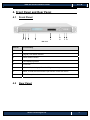
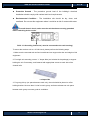
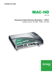
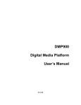
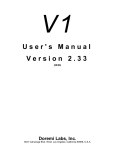
UMH 160 Quick Installation Guide V1.1-W UMH160 Integrated Digital Receiver Quick Installation Guide Wellav Technologies Ltd. 1 UMH 160 Quick Installation Guide V1.1-W Preface About This Document This document provides introductions and guidelines to users about how to install and operate this equipment quickly. Disclaimer Wellav Technologies Ltd. assumes no responsibility for errors or omissions that may appear in this publication. It reserves the right to change this publication at any time without notice. This document is not to be construed as conferring by implication, estoppel, or otherwise any license or right under any copyright or patent, whether or not the use of any information in this document employs an invention claimed in any existing or later issued patent. Intended Readers z Technical Service Engineer z Maintenance Engineer z Test Engineer z Sales Engineer Symbols Definition For the symbols that might appear in this document, the meanings they represent are as the following: Symbol Meaning There is potential danger. If it cannot be avoided, it will lead to the deaths or serious injury. There is medium or low potential danger. If it cannot be avoided, it will lead to medium or mild injury. Wellav Technologies Ltd. 2 UMH 160 Quick Installation Guide V1.1-W There are potential risks. If ignore these texts, it may cause damage to the device, data loss, equipment performance reduce or unpredictable results. Tips that help you to solve problems or save your time. Remarks. Additional information to the text, in order to emphasize something. Revision History The revision history lists the modification history. The newest one contains all the modifications of the past revision. V1.00: First revision. (Date: March 5th, 2012) Wellav Technologies Ltd. 3 UMH 160 Quick Installation Guide V1.1-W Content 1. Safety ............................................................................................................................ 5 2. Check Package and Accessories .................................................................................. 6 3. Physical specifications ................................................................................................... 7 4. 5. 6. 3.1 Physical Specifications .......................................................................................... 7 3.2 Interfaces and data IN/OUT capabilities ................................................................ 7 Front Panel and Rear Panel .......................................................................................... 9 4.1 Front Panel ............................................................................................................ 9 4.2 Rear Panel ............................................................................................................. 9 Installation Instruction .................................................................................................. 10 5.1 Mounting unit to a 19” rack .................................................................................. 10 5.2 Wiring Connection ............................................................................................... 12 5.3 Power Connection ............................................................................................... 13 Operation Instructions ................................................................................................. 14 6.1 Powering Up & Initializations ............................................................................... 14 6.2 Network Connection Setup .................................................................................. 14 6.2.1 Navigation Keys Operation Instruction ............................................................. 14 6.2.2 Check Out and Change the Default IP Address ............................................... 15 6.2.3 Configuration through WEB Management........................................................ 16 6.3 Quick Configuration on Key Parameters .............................................................. 18 6.3.1 Check “Status” tab............................................................................................ 18 6.3.2 Configure parameters of signal input modules ................................................. 18 6.3.3 Configure parameters of signal output modules ............................................... 23 6.3.4 Change the password ...................................................................................... 28 6.3.5 Check “Status” again ........................................................................................ 29 Wellav Technologies Ltd. 4 UMH 160 Quick Installation Guide V1.1-W 1. Safety z To avoid electric shock hazards, do not open the receiver; refer service to qualified personnel only. z Do not expose the device in the sunlight, and keep it away from the heat source. z Do not block ventilation holes of the device so that air can circulate freely. z Switch the device off whenever it remains out of service for an extended period. z Be sure to turn the device off and disconnect the AC power cord before cleaning the receiver surface. z The device shall be connected the mains socket outlet with a protective grounded connection z The appliance coupler used as the disconnect device shall remain readily architecture Wellav Technologies Ltd. 5 UMH 160 Quick Installation Guide V1.1-W 2. Check Package and Accessories The Receiver package includes the following accessories: z UMH160 Base Unit x1 z Power cord x1 z Earth cord x1 z BNC cord x1 z BNC-RCA cord x2 z User manual Disc x1 Please contact the supplier if it is inconsistent with the actual package. Wellav Technologies Ltd. 6 UMH 160 Quick Installation Guide V1.1-W 3. Physical specifications 3.1 Physical Specifications Items Index Power AC 90V-260VAC, 50/60Hz Power Consumption Approx 125W Size 1RU Dimension 482mm(L) x44mm(W) x 393mm(H) Net Weight Approx 3.8Kg Gross Weight Approx 5Kg 3.2 Interfaces and data IN/OUT capabilities Physical Connector Interfaces Inputs ● DVB-S/S2 Input Constellation: QPSK, 8PSK Symbol Rate: 1~45 Mbps FEC: All rations compliant with standard Signal Level: -65 ~ -25 dBm ● DVB-T Input(optional) Contellation: COFDM, 2K & 8K FTT Symbol Rate: 0.45~7 Mbps (QPSK) Frequency: 174 ~ 230 MHz, 474 ~ 858 MHz Signal level: -80 ~ -20 dBm ● DVB-C Input(optional) Constellation: QAM ( 16 / 32 / 64 / 128 / 256 ) Symbol Rate: 3 ~ 6.9 Mbps Frequency: 48 ~ 862 MHz Signal level: 32 ~ 100 dBuV ● ISDB-T Input (optional) Constellation: OFDM (64QAM / 16 QAM / QPSK / DQPSK), 2K, 4K, & 8K FTT Frequency: 470 ~ 806 MHz Bandwidth: 6 MHz Input impedance: 75 Ω Input level: -90 ~ -5dBm Wellav Technologies Ltd. 7 UMH 160 Quick Installation Guide V1.1-W ● DVB-ASI Input Connector: BNC, 75 Ω Packet Length: 188 & 204 byte packets TS Max Bit Rate: 72 Mbps ● TS/IP Inputs (optional) Connector: 100/1000Base-T, RJ-45 FEC: Pro-MPEG Encapsulation Protocol: UDP & RTP Broadcasting type: Unicast and Multicast Outputs ● Video/Audio Outputs 2xCVBS outputs (1 BNC, 1 RCA) 1xComponent output (YPbPr) 1xHDMI output (with HDCP, 720p & 1080i) 1xAES/EBU digital audio output 2xHD/SD-SDI outputs (with embedded digital audio) ● DVB-ASI Outputs Connector: BNC, 75 Ω Packet Length: 188 & 204 byte packets TS Max Bit Rate: 72 Mbps ● TS/IP Outputs (optional) Connector: 100/1000Base-T, RJ-45 FEC: Pro-MPEG Up to 8 streams Multicast or Unicast Broadcasting type: Unicast and Multicast Supporting Protocol: DHCP, TCP/IP, ARP, IGMP (V2/V3) ● Analog Unbalanced Audio L-AUDIO-R Output Interface: RCA*2, 1 groups of Left/Right Channel audio Max Output Level: 7 dBu Output Impedance: 600 ohm ● AES/EBU Output Interface: XLR*1 Max Output Level: 2~5V peak to peak Output Impedance: 110 ohm z Management Management Port Interface: 100BaseTX,RJ45 Web-based Management Wellav Technologies Ltd. 8 UMH 160 Quick Installation Guide V1.1-W 4. Front Panel and Rear Panel 4.1 Front Panel 1 2 3 4 5 6 7 8 PIC-4.1-1 Item No. Functionality 1 Power status indicator 2 (Signal) Lock status indicator 3 Alarm status indicator 4 LED displaying screen 5 CI SLOTS 6 KEY PADS, including Up/Down/Left/Right arrow keys 7 Menu. To enter the menu and the quit function of the sub menus. 8 ESC. The quit function of the menu. 4.2 Rear Panel Wellav Technologies Ltd. 9 UMH 160 Quick Installation Guide V1.1-W 5 1 2 3 4 6 8 9 7 8 9 PIC-4.2-1 10 11 12 13 Item No. Functionality 1 TS/IP: TS stream input and output as IP format 2 AES/EBU: Professional digital Audio output with XLR connector. 3 HDMI: Output high quality picture and sound with one cable. 4 Cr/Cb/Y: Component output. 5 VIDEO /AUDIO: Video signal output jack and Left/right audio output jack. 6 ASI IN: BNC connector for TS input. 7 CVBS OUT: Output video with BNC interface. 8 SDI OUT: Output the SDI Video stream. 9 ASI OUT: Output MPEG-2 or Mpeg-4 TS. 10 ETHERNET: 11 TUNER OUT (LOOP OUT): Use it when connecting to another IRD. 12 TUNER IN: Connect to a RF or IF signal. 13 POWER SUPPLY and POWER SWITCH: 90~250V AC, 50Hz. The port is used in network remote control. Inrush Current at initial switch on: 1.55A. Inrush Current after power supply interruption: 2.3A. 5. Installation Instruction 5.1 Mounting unit to a 19” rack When selecting the installation site, try to comply with the following: Wellav Technologies Ltd. 10 UMH 160 Quick Installation Guide V1.1-W z Protective Ground - The protective ground lead of the building's electrical installation should comply with national and local requirements. z Environmental Condition - The installation site should be dry, clean, and ventilated. Do not use this equipment where it could be at risk of contact with water. To avoid electric shock, make sure the rack has been correctly grounded before switching device on the. PIC-5.1-1 Grounding Jackscrew ( must be connected to the rack housing) To mount the receiver unit to a 19”/42U rack, please perform the following steps: 1. Make sure the mounted rack surface is stable and can support the size and weight of this equipment. 2. For single unit mounting, use an “L” shape slide (not included in the package) to support holding the unit if necessary, and fastened with appropriate screws to each side of the chassis’ rails. L-shape slide 3. For group pile up (no space between each unit), the unit should be placed on a flat holding bracket. No more than 5 units for each group, and leave at least one unit space between each group to ensure good air ventilation. Wellav Technologies Ltd. 11 UMH 160 Quick Installation Guide V1.1-W PIC-5.1-2 5.2 Wiring Connection Before setting up the connection, please turn off the equipment and all other connected external devices. The equipment and all connected external devices are required grounded. Turn on the devices only after the wiring connection is completed. Otherwise, the device may be damaged. Follow the below connection diagram to set up cable connection: 1 3 4 2 5 PIC-5.2-1 z Set up cable connection for input signal: either the RF input or ASI input. z Set up cable connection for output signal: either through ASI or HDMI/ CVBS/SDI. z Set up connection for network management control. In order to ensure a smooth communication between the management PC and Wellav Technologies Ltd. 12 UMH 160 Quick Installation Guide V1.1-W the equipment, please separate the connection of management port and TS/IP output port to different switch. The switch with management port connected should be without large data processing. The TS/IP port can work for input and output simultaneously. User only needs to connect one RJ45 cable to the TS/IP port of the device. 5.3 Power Connection Connect this equipment only to the power sources that are identified on the equipment-rating label normally located close to the power inlet connector(s). Always pull the plug or the connector to disconnect a cable. Never pull on the cable itself. To protect your valuable interests and services, equipping a UPS (Uninterrupted Power Supply) and an AVR (Automated Voltage Regulator) to the system is highly recommended. Wellav Technologies Ltd. 13 UMH 160 Quick Installation Guide V1.1-W 6. Operation Instructions 6.1 Powering Up & Initializations Before powering-up the device, make sure that all cabling is correctly connected (refer to chapter PIC-5-2-1). The device is correctly connected to the power inlet and grounded. Switch on the equipment through the back power switch, the unit is powered up and start the initialization. The LCD screen is lighted up, and display information as following: UMH160 Setting System PIC-6.1-1 The initialization takes about 30 seconds to complete. If the unit fails to initialize and hangs at the “booting” stage, swtiching off the device and then powering up again. If the device still fails to initialize, please contact your service representative for help. The input/output indicator LEDs turn red after successful initialization because of signal unlocking. After configuration on the device, corresponding LEDs shall show correct statuses. 6.2 Network Connection Setup 6.2.1 Navigation Keys Operation Instruction Use the 6 navigation keys on front panel: Up / Down / Left / Right / Menu / Ok to Wellav Technologies Ltd. 14 UMH 160 Quick Installation Guide V1.1-W enter the configuration menu. z Enter “Menu”: z Press “MENU” button to enter main menu. Exit Menu/Back to parent Menu Upon completion of configuration settings, press “MENU” button until you go back to the Parent Menu. z z You can also go back to Parent Menu directly by pressing “ESC” button once. Enter Sub-Menu Press MENU button to enter main menu. Select a sub-menu by pressing UP and DOWN button. Press OK button on the selected sub-menu. To change parameter Step 1: Enter main menu by pressing MENU button. Step 2: Scroll sub-menu by pressing UP and DOWN button, and press OK button to change the selected sub-menu. Step 3: To change parameter settings, press RIGHT and LEFT button to move the cursor in which change must be made. Press UP button and DOWN to input / select an appropriate setting, then press OK button to save. 6.2.2 Check Out and Change the Default IP Address z Step 1: check out the IP on the LCD screen. z Step 2: use the button on the front panel to change the IP, gateway and subnet mask. The gateway should be the same as the management PC’s. The subnet mask should be the same as the management PC’s s. The IP and the server’s IP should be in the same section. z Step 3: reboot the device to take effect. z Step 4: ping the new IP on PC to check whether the device can connect to the management PC. Wellav Technologies Ltd. 15 UMH 160 Quick Installation Guide V1.1-W 6.2.3 Configuration through WEB Management Accessing the equipment through web can be very convenient for remote configuration of the equipment. Relative to the front panel settings, web operation can provide a more user-friendly man-machine interface, and less limits in space. For quick installation, web operation is highly recommended. In this installation guide, operation instruction is based on web style. For front panel operation instruction, please refer to product user manual. z Preparation before connection Open any web browser (e.g. Mozilla, internet explorer, safari etc.), input the equipment’s IP address in format: http://xxx.xxx.xxx.xxx (xxx.xxx.xxx.xxx refers to IRD’s IP address) and press ENTER button to confirm. The browser will attempt to connect to the device. If succeed, a login page will appear (see pic-6-2-1). z First Time Log On o For first time log on, User Name and Password are required. Default User Name and Password are “admin”. PIC-6.2-1 Wellav Technologies Ltd. 16 UMH 160 Quick Installation Guide V1.1-W User can change the password after log on the device. Please refer to chapter XXXX of this document for the details. (Referring chapter 6.3.4) Possible reasons for unsuccessful log on: z z IP address/ network mask/gateway don’t match with the management PC’s z User name/password is wrong. z The device is connected to the wrong interface. Main Interface Introduction After logging in successfully, it will search the HD IRD which is connected to the server and display it on the left side as below automatically. PIC-6-2-2 The main interface can be divided into two areas according to its functionality. 1.Menu: It share same 6 tabs including “Status”, “Inputs”, “Outputs” and “System”. 2.Parameter setting and configuration area: The parameters of the equipment are shown and configured here by selecting corresponding tabs. This is the main operation area of the WEB management. Wellav Technologies Ltd. 17 UMH 160 Quick Installation Guide V1.1-W 6.3 Quick Configuration on Key Parameters 6.3.1 Check “Status” tab Click the “status” tab on the left area and then the status information will show on the right interface as following, where you can check the main information of the device. PIC-6-3-1 6.3.2 Configure parameters of signal input modules Firstly, click the receiver menu to obtain the receiver interface, where you can configure the detailed parameter as follows: Wellav Technologies Ltd. 18 UMH 160 Quick Installation Guide V1.1-W Step one Step three Step four Step two PIC-6-3-2 z Tuner IN If you need to receive the signal from satellite via the device, just connect the satellite siganl to the tuner port and operate as follows: -Step one: PIC-6-3-3 Choose the signal as input ,there are three options:ASI, Tuner and IP, here we choose tunel as siganl source. After confirm the signal source, it is able to go for further configuration. -Step two: Configure the dual RF receiver parameters including the Satellite Frequency, Symbol Rate, LNB Frequency, and LNB Voltage (Polarization) with accurate values to ensure a successful receiving. You can get the value for the parameter from the satellite operator Wellav Technologies Ltd. 19 UMH 160 Quick Installation Guide V1.1-W PIC-6-3-4 z SATELLITE FREQUENCY (MHz): this is the satellite down conversion frequency, every transponder has one frequency, and this parameter can be obtain from the satellite program provider or at www.lyngsat.com z SYMBOL RATE (KBaud): every transponder has one symbol rate; this parameter can be obtain from the satellite program provider or at www.lyngsat.com z LNB LO. Frequency: this is the LNB’s local oscillation (LO) frequency, every LNB have one or two oscillation frequencies that can be obtained from the LNB provider, or you can check on the LNB label. The value is between 5000 and 6000.. -Step three By changing the CAM operation, you can determine whether to descramble the program or not. o BYPASS: to transmit the program without any disposal. o CI SLOT 1 / CI SLOT 2: Common Interface slot. If the program is scrambled, you can appoint the CAM module with CAM Card to scramble it. Under this condition, the program is transmitted in default. o DELETE: any program you don’t want to transmit can be forbidden by selecting this status. Wellav Technologies Ltd. 20 UMH 160 Quick Installation Guide V1.1-W -Step four After that press the “Submit” button to save your settings, and click “Refresh” button to refresh the screen to check if the signal is locked. Step two z ASI IN Step One Step three PIC-6-3-5 -Step one When choosing the ASI signal as input, check the ASI siganl first to ensure a high-quality source, then connect the ASI signal to the ASI interface on rear panel. -Step two By changing the CAM operation, you can determine whether to descramble the program or not. o BYPASS: to transmit the program without any disposal. o CI SLOT 1 / CI SLOT 2: Common Interface slot. If the program is scrambled, you can appoint the CAM module with CAM Card to scramble it. Under this condition, the program is transmitted in default. o DELETE: any program you don’t want to transmit can be forbidden by selecting this status. -Step three Choose the ASI signal as signal source and click “submit” button to confirm. After that click “refresh” button to refrsh the status page to check if the signal is locked. Wellav Technologies Ltd. 21 UMH 160 Quick Installation Guide V1.1-W z IP IN -Step one When need to choose IP stream as input source, click the sub-menu “IP Input” sub-menu in “IP” menu. Then it can turn to the IP parameter interface. Step one PIC-6-3-6 -Step two Before the receiving of IP signal, make sure the IP address of the IP board is correctly set. It should be set to be compliant with the signal source. Wellav Technologies Ltd. 22 UMH 160 Quick Installation Guide V1.1-W Step Three Step two PIC-6-3-7 -Step Three Then, set the “Enable” item to be “ON” to access the IP channel and set the source IP address, Source Port and Protocol. The Source IP address shall be in the same section with that of signal source, and the Source Port and protocol shall stay same with that of signal source. -Step Four Press “Submit” button to confirm the parameter. And press the “Status” menu in the left area to refresh the receiving information to check if the signal is locked. 6.3.3 Configure parameters of signal output modules z Decoder OUT The device allows various signal outputs, including HDMI, SDI, CVBS. In this interface, user can view and configure the decoding output program information, including: Video, Audio, and HDMI/SDI. Wellav Technologies Ltd. 23 UMH 160 Quick Installation Guide V1.1-W Step one Step two PIC-6-3-8 -Step One: choosing programs z Playing Program: This interface, all the programs received will be listed in “Source Select” region. By changing the program’s operation, you can determine which program to transmit. PIC-6-3-9 If the input signal is not locked or searched, the “program” section shows empty. User cannot do any setup for the moment. -Step Two: set program parameter z VIDEO: Then configure the video parameter such as Video Standard, Aspect ratio Conversion and Output Video resolution as follows: Wellav Technologies Ltd. 24 UMH 160 Quick Installation Guide V1.1-W PIC-6-3-10 The device decoding output is via its CVBS or HDMI output ports. For each time only one program can be set to decoding output. z Audio: In addition, you can configure the information of Audio such as volume, and audio language, as following: PIC-6-3-11 o AUDIO Volume: Set the output audio level from 0 to max. 49. o AUDIO LANGUAGE: Select different audio language if there are multiple audio PIDs contained in the signal. z SDI/HDMI Here it is able to set the resolution of HDMI or SDI videos. PIC-6-3-12 z ASI OUT The ASI interface transmits the received signals out for further process. To guarantee the Wellav Technologies Ltd. 25 UMH 160 Quick Installation Guide V1.1-W successful transmission, you should make sure the signal has already been locked. . z IP Out: When need to choose IP stream as input source, click the sub-menu “IP Input” in “IP” menu. Then it can turn to the IP parameter interface. Step one PIC-6-3-13 -Step two Before the setting of IP output channels, you should choose the IP channel that you want to use. The relative parameter of the channel will appear on the right frame as follow: Step Two Step Four Step Three PIC-6-3-14 -Step Three Then, set the “Enable” item to be “ON” to access the IP channel and set IPDestAddress, Wellav Technologies Ltd. 26 UMH 160 Quick Installation Guide V1.1-W IPSourcePort and UDPDestProtocol. The IPDestAddress is the address which you want to send the streams to. (Refer to chapter 6.3.3.3) Enable the FEC function and set the parameters, if you want this Function. ColFEConly: No means both Col and Row FEC; Yes means Col FEC only. -Step Four Here it it able to check the programs that converted in the IP channel. 6.3.3.3 Multicast and unicast for IP z multicast application In multicast application, it is simple to connect the physical equipment, and the following picture shows a typical connection and parameters setting. You just need set the parameters listed in this picture. PIC-6-3-15 The important point is to make sure the multicast address, protocol and port number are the same in both ‘IRD_Sender’ and ‘IRD_Receiver’. Regarding how to enter the menu to set these parameters, please refer to the chapter ‘front panel/NMS control and operation’. Note: Wellav Technologies Ltd. 27 UMH 160 Quick Installation Guide V1.1-W 1) The IRD supports IGMP v3, please note the IGMP version that your router supports. 2) The ‘Speed Mode’ in front panel should be set the same to your switch/router. 3) The quantity of programs transmitted via IP channel depends on the speed mode (10M/100M/1000M) of the switch or router, which connects to the IRD. The total bitrates you want to transmit should less than the most speed which the switch or router takes, otherwise, the quality of programs will decrease, even the programs cannot be transmitted through switch or router. z unicast application The unicast involves two local area networks connecting each other via Internet. Compare with multicast, the connection and parameter setting of unicast are a little complicated. The following picture shows a typical connection and parameter setting for unicast application. You need set the parameters listed in this picture. PIC-6-3-16 6.3.4 Change the password Choose “User management” menu and you will get the operation interface. Select the username and input the old password correctly, then you are able to change the password. After inputting the new password, please click submit button to enforce the configuration. Wellav Technologies Ltd. 28 UMH 160 Quick Installation Guide V1.1-W PIC-6-3-17 6.3.5 Check “Status” again Turn to status page to check if the configuration has come into effect. PIC-6-3-18 This is the brief introduce of quick installation, if need more detail or complete information for the device please refer to the user manual. Wellav Technologies Ltd. 29