1
HOW TO INSTALL YOUR EXPRESSIONS 520 POWER SHOWER
WHAT TO DO IF THINGS GO WRONG (1)
SELF HELP
If the shower is not working satisfactorily, make the following checks before calling out the installer.
Any one of these adjustments could restore the performance.
System will not operate Check that the mains electricity supply is switched on.
Pump operates but no
Check water is available to both ports, and that all isolating valves are open.
water is delivered
Check for an air-lock in the pump chamber.
Water too COLD
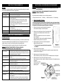
Turn Temperature Control Knob “B” anti-clockwise in the direction of the
“red arrows” (Diagram 10).
Check that hot water is available in the hot water cylinder. The ideal
thermostat setting for the hot water storage cylinder is 60°C (140°F).
Check that the HOT water isolating valve is open.
If possible, reposition temperature limiting device so that more movement
of knob “B” is allowed.
Water too HOT
Turn Temperature Control Knob “B” clockwise in the direction of the “blue
arrows” (Diagram 10).
Check that the COLD water isolating valve is open.
Spray pattern poor
Clean the shower handset. Select an outer/inner spray pattern.
Broken parts
Please contact our spares department on 0844 372 7750
WARNING: ALL WIRING AND INSTALLATION MUST BE SUPERVISED BY A SUITABLY
QUALIFIED PERSON.
WARNING: DO NOT INSTALL THIS SHOWER WHERE IT MAY BE SUBJECTED TO
FREEZING CONDITIONS
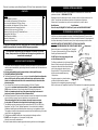
We recommend that the installation is done in the following sequence.
a. Fixing the shower to the wall
b. Plumbing
c. Electrical connections
a. FIXING THE SHOWER TO THE WALL
The Redring Expressions 520 power shower is fitted with a motor and some mechanical
noise can be expected when in use. The type of wall structure will affect the noise levels.
Solid walls will provide quieter operation than panel or stud walls.
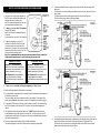
1. Position the riser rail at a convenient height for the majority of
users as detailed in Diagram 1 and mark its position.
If the previous “Self Help” checks fail to restore the performance, you should seek professional help.
2. Position the unit so that the top of the unit is horizontal and that
all controls can be comfortably reached whilst the shower is
being used.
Ensure correct orientation of the shower unit ie: mounted as
shown in Diagram 1.
Choose a flat piece of wall to avoid the possibility of distorting the
backplate thus making the front cover a poor fit.
The person who installed the shower is probably the best one to investigate and correct it and is
certainly the person to contact if you have had a problem in the guarantee period.
3. Adjust the position to get the most convenient arrangement
taking the following into account.
WHAT TO DO IF THINGS GO WRONG (2)
PROFESSIONAL SERVICE
The following additional checklist is provided for the benefit of the qualified service person.
WARNING: SWITCH OFF THE ELECTRICITY AT THE LOCAL ISOLATOR
BEFORE REMOVING THE COVER TO MAKE CHECKS
Pump operates but no Check the inlet connections to the mixing chamber are piped correctly.
water is delivered
Check that the shower and all pipe work are sited below the level of the
cold water tank and that it is fully primed and is therefore not air-locked.
(See commissioning procedure on page 7).
Pump operates when
Check for faulty potentiometer switch, located under knob “A” inside
motor is switched off
front cover.
Switch should be open circuit when turned fully anti-clockwise.
Water too hot
Blockage in filter causing obstruction in water supply.
Check and clean (see page 11).
Water too cold
Blockage in filter causing obstruction in water supply.
Check and clean (see page 11).
Poor temperature
Check the hot and cold water supplies are delivered to the correct ports.
adjustment
Check that water is supplied to the shower unit at balanced pressures
(ie Hot and Cold water are supplied from the same header tank).
Ensure cold water supply is not taken from mains.
Unit does not prime
Check that the shower and all pipe work are sited below the level of the
cold water tank.
Poor flow rate
Check for any restrictions in the Ø15mm supply (reduced diameters even
for short distances).
Check that pressure is not being lost to other services in the dwelling.
Check filter for obstructions in the water supply and clean if necessary.
10
d. Commissioning
•
The unit must not be mounted in the direct spray from
the handset.
4. Fix the riser rail with screws provided.
The fixing holes at the base of the brackets will be revealed by removing the plastic fronts.
Assemble as shown in Diagram 13.
5. Decide the position of the electrical cable into the unit.
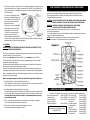
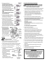
If top or bottom entry is chosen, cut away the walls in the backplate as shown in Diagram 2.
6. Decide the position of entry of the cold water pipes into the unit.
If top or bottom entry is chosen, carefully cut away the relevant walls of the backplate as shown
in Diagram 2.
If bottom entry is chosen,
refer to note 9 in the
plumbing section.
3