1
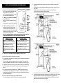
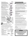
7. If you have not yet done so, remove the front cover assembly by undoing the retaining screws at
the top and bottom of the unit. Remove Temperature Control Knob “B” Cap (see Diagram 10) by
levering out carefully with a small flat bladed screwdriver and remove the small fixing screw as
shown in Diagram 3.
Your shower is provided with 4 fixing
positions in the backplate (Diagram 11).
The top-fixing holes are “key-hole” slots
and the most convenient should be
marked and drilled first.
HOW TO MAINTAIN YOUR EXPRESSIONS 520 POWER SHOWER
It is recommended that the shower unit and hose etc. be cleaned using a soft cloth and that the use
of abrasive or solvent based cleaning fluid be avoided, especially on any plated finishes.
We recommend that before any cleaning, the isolating switch be turned off, thus avoiding
accidentally switching on the shower.
WARNING: YOU MUST REGULARLY INSPECT THE SHOWER HOSE FOR WEAR AND DAMAGE.
REPLACE IF NECESSARY, OR EVERY TWO YEARS, WITH AN APPROVED PART.
WARNING: IN ORDER TO MAINTAIN THE PERFORMANCE OF YOUR SHOWER,
YOU MUST CLEAN THE SHOWER HANDSET REGULARLY
Tighten top screw with head protruding
about 10mm from the wall and hook
the backplate over the screw head.
This allows for correct and accurate
alignment of your shower before
marking and fixing the bottom position.
You may not wish to tighten up both screws at this stage as the holes are elongated to allow for
adjustment after other connections have taken place.
All water contains particles of lime-scale, which build up in the shower handset and
unit reducing the performance.
It is therefore important to clean the shower handset by soaking in proprietary lime-scale remover
ensuring it is rinsed thoroughly before use.
NOTE: After use it is normal for some water to drip from the shower handset for
a few moments. This inhibits scale build-up over prolonged use.
b. PLUMBING
WARNING: UNDER NO CIRCUMSTANCES SHOULD THIS UNIT BE CONNECTED TO THE
MAINS COLD WATER SUPPLY.
The unit must be connected to a cold water supply gravity fed from a static cold water cistern with
a minimum capacity of 114 litres (25 gallons).
There must be a minimum head of water of 8cm (3”) and a maximum head of 10m (33ft).
It is strongly advised to install the shower unit using an independent supply from the cold water
storage cistern and hot water cylinder.
The shower would be totally unaffected by the other draw off points elsewhere in the system and
thus the pressure and temperature will remain more stable.
Therefore, the cold water supply should be taken directly from the cold water cistern and the hot
water supply should be taken from the hot water cylinder via an Essex or Surrey Flange (Diagram 4)
Under no circumstances should any of the pipework supplying the shower unit rise above the level of
the bottom of the cold water cistern.
Before connecting the pipework to the shower ensure that the pipework is flushed out.
1. Surrey Flange (Top entry cylinder flange) Fitting Instructions.
The hot connection to the shower unit can be taken directly from the hot cylinder using a Surrey
Flange. Diagram 4 shows how this flange should be fitted.
2. Essex Flange (Side entry cylinder flange) Fitting Instructions.
Alternatively, the hot connection to the shower can be taken directly from the hot cylinder using
an Essex cylinder flange and extension pipe. Diagram 4 shows how this flange should be fitted.
Connecting direct to the side of the cylinder is not recommended where a top entry
immersion heater is fitted.
3. The hot connection can also be taken from the hot supply to other outlets as in Diagram 5.
The connection must be made below the ventilation tee.
4. The thermostat on the hot water cylinder should ideally be set at 60°C.
The maximum permissible inlet temperature is 65°C.
4
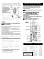
ADDITIONAL ACCESSORIES
COMMON SPARE PARTS
Please Note:- The fitting of Spare Parts must be supervised by a suitably qualified person.
White 2 metre Shower Hose
Cat No. 83792578 Front Cover (520M)
Cat No. 93797625
1 metre Riser Rail
Cat No. 83595313 Front Cover (520TS)
Cat No. 93797626
Curtain and Rail Pack
Cat No. 83792812 Pump Motor Assy
Cat No. 93797636
Curtain and Rail Pack
Control Knob
Cat No. 93797627
with Non-Slip Bath Mat
Cat No. 83792811 Control Knob (Small)
Cat No. 93797628
Potentiometer Assy
Cat No. 93797629
Additional accessories and spare parts can be
Filter Pack
Cat No. 93797632
supplied against any Credit or Debit cards
1.25m Chrome Hose
Cat No. 93797641
Ring: 0844 372 7750
Combined Inlet Elbow
Cat No. 93797631
Motor Bush Pack
Cat No. 93797637
9