1
into any position, in any site, without the need to perform on-site reprogramming. This can be convenient in maintenance situations.
The parameters that can be defined on a per channel basis are:
•
•
•
•
•
•
•
•
The frequency, or if scanning is enabled, the list of frequencies to be scanned.
If scanning is enabled, the selection of a priority frequency (if there is one),
and how often it is checked.
The CTCSS tone, or tones, expected on each frequency, or, DCS code
expected on each frequency.
The delay from the opening of the squelch till the assertion of the COS output,
or LOOP output.
The delay from the closing of the squelch to the negation of the COS or LOOP
output.
Whether or not LOOP and/or COS should be asserted when the squelch opens,
depending on which frequency, and/or CTCSS tone, is detected.
Whether de-emphasis should be applied to the tuned signal or not depending
on which frequency the receiver is tuned to.
Offsets for carrier strength or SINAD: the user can allow individual
frequencies to have higher or lower thresholds for SINAD or carrier strength.
7.1.2 CTCSS
Full EIA subtone Capability is built into the modules. The CTCSS tone can be
programmed for each channel. This means that each channel number can
represent a unique RF and tone frequency combination.
7.1.3 DCS
From Rev. 4 hardware and Rev. 4 firmware, support for DCS codes is supported.
DCS code generation can be enabled on a per channel basis. If enabled, the
receiver will not open the squelch unless it is receiving the nominated DCS
code, or one of its valid transformations. If it stops receiving these DCS codes,
the squelch will close.
7.1.4 Channel Pr ogr amming
The channel information is stored in non-volatile memory and can be programmed via
the front panel connector using a PC, and/or RF Technology software.
7.1.5 Channel Selection
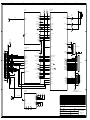
Channel selection is by eight channel select lines connected to the rear panel that
mounts on the rear DB25 female connector.
A BCD active high code applied to the lines selects the required channel. This can be
supplied by pre-wiring the rack connector so that each rack position is
dedicated to a fixed channel. Alternatively, thumb-wheel switch panels are
available.
By redefining “illegal” BCD codes, users can also encode channels from 100 – 255.
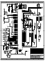
7.1.6 Micr opr ocessor
A microprocessor is used to control the synthesizer, tone squelch, calibration, fault
monitoring and reporting, RSSI reading, deviation measuring, option setting
and facilitate channel frequency programming.
RF Technology R50
Page 17