1
Installation, cont’d
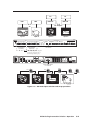
Audio connections
8
9
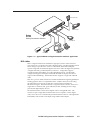
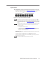
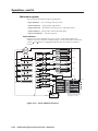
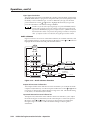
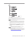
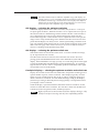
Input 1 through Input 5 connectors — Connect unbalanced stereo or
mono audio sources (such as DVD players or VCRs) to these pairs (left
and right) of RCA connectors for audio input.
L
R
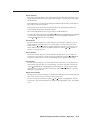
Input 6 through Input 8 connectors — Connect unbalanced stereo audio
sources (such as computers) to these 3.5 mm mini stereo jacks for unbalanced
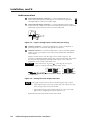
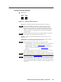
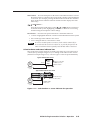
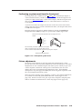
audio input. Figure 2-3 shows how to wire the audio jack.
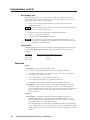
Tip (L)
Ring (R)
Sleeve ( )
Figure 2-3 — Input 6 through input 8 audio connector wiring
10
Output A connector — Connect an audio device, such as an amplifier or
powered speakers, to these left and right RCA connectors.
11
Output B connector — Connect an audio device, such as powered speakers,
to this 3.5 mm, 5-pole captive screw connector for balanced or unbalanced
audio output.
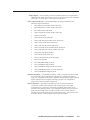
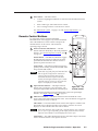
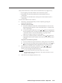
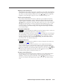
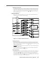
Figure 2-4 shows how to wire the captive screw audio connector. The
connector is included with the switcher, but you must obtain the cable. Insert
the wires into the appropriate openings in the captive screw connector.
Tighten the screws on top to fasten the wires.
CAUTION
Connect the sleeve(s) to ground ( ). Connecting the sleeve(s) to a
negative (-) terminal will damage audio output circuits.
Tip
Ring
R
Right
Tip
Ring
Left
R
Left
L
L
Tip
NO GROUND HERE.
Sleeve(s)
Tip
NO GROUND HERE.
Right
Unbalanced Stereo Output Balanced Stereo Output
Do not tin the wires!
Figure 2-4 — Wiring the audio output connector
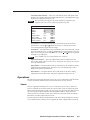
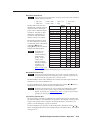
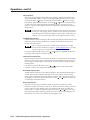
The length of exposed wires is critical. The ideal length is 3/16” (5 mm).
• If the stripped section of wire is longer than 3/16”, the exposed wires may
touch, causing a short circuit between them.
• If the stripped section of wire is shorter than 3/16”, wires can be easily
pulled out even if tightly fastened by the captive screws.
By default, the audio output follows the video switch.
2-4
IN1508 Scaling Presentation Switcher • Installation