1
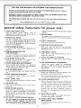
Serial
Number ...........................
Model and serial
number may be found
on the right side
of the base.
You should record both
model and serial number
in a safe place for
future use.
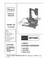
I INCH
CAUTION:
SANDER
Read GENERAL
and ADDITIONAL
SAFETY
. assembly
INSTRUCTaONS
® operating
carefu|ly
Sold by SEARS,
Part No, 68038
® repair
ROEBUCK
AND
CO.,
GRINDER
parts
Chicago,
I L. 60684
U.S.A.
......
• -,
:
i••¸¸¸•¸ _LL_',
FULLONE
....
•, •;•, _ ....
• •
•• ....
, •,•,• •
YEAR WARRANTY
"•,;........
L• ,-
q•,i ¸ -
i
ON CRAFTSMAN
•,
•
• ••
1 INCH SANDER/GRINDER
to a defect
in
state.
SEARS. ROEBUCK AND CO., Sears Tower. 8S0 41-3. Chicago, IL 60684
i
general
safety
1. KNOW YOUR
Read
the
for power
POWER TOOL
:owner's
appticati0n
arid
potential
hazards
2. GROUND
instructions
manual
carefully.
limitations
as welL;as
peculiar to this t0ot.
Learn
the
protectors
operation.
its
and
in
4. REMOVE ADJUSTING
AND WRENCHES
proper
adjustment
Keep proper
and
extended
periods
of
at all t_mes,
TOOLS WITH CARE
16. DISCONNECT
17 • AVOID
changing
ACCIDENTAL
Make sure switch
in.
Floor
Consult
Don't
use power,:tO0]s
in damp Or wet locations
or
expose: them to ,rain, Keep:worE
area well lighted,
Provide adequate surrounding
work space,
the
safest
and
owner's
accessories
such
as
STARTING
is in "OFF"
18. USE RECOMMENDED
ENVIRONMENT
for
best and
for lubricating
TOOLS
before
servicing;
when
blades, bits, cutters, etc,
AREA CLEAN
DANGEROUS
and batance
Keep
tools
sharp
and clean
performance,
Follow
instructions
changing accessories.
:KEYS
Cluttered
areas: and benches
invite accidents.
must not be slippery due to wax or sawdust.
6, AVOID
footing
15. MAINTAIN
Form habit
of checking
to see thal keys and adjusting
Wrenches are removed
from toot before turning
it on.
5, KEEP WORK
during
14. DON'T OVERREACH
IN PLACE
order;
(plugs or muffs)
Use clamps or a vise to hold work when practical.
It's
safer than using your hand, frees both hands to operate
tool.
This tool iS equ pped w th an approved
3-c0nductor
cord and a :3-prong, ground ng type-plug
to fit the
proper grounding
type [eceptacle. ]:he green conductor
in the cord is the gr0Undilr_g wire Never com_ect the
green wire to alive terminal.
i_ working
alignment,
tools
1_3.SECURE WORK
specific
ALL TOOLS
3, KEEP GUARDS
,, ,,
position
before
plugging
ACCESSORIES
manual
for
accessories. Follow
the instructions
the accessories.
The use of _mproper
cause hazards.
recommended
that accompany
accessories may
7. KEEP CHILDREN:AWAY
Al visitors
area.
should
be kept
8. MAKE WORKSHOP
with
padlocks,
starter keys.
a Safe distance
from
19. NEVER STAND
Work
KID-PROOF
master
switches,
or
by
removing
10. USE RIGHT
Don't force tool
designed for,
20. CHECK DAMAGED
and safer at the rate for which
Before
to do a job
it was not
11. WEAR PROPER APPAREL
GOGGLES
PARTS
use of the tool
a guard or other
Check
for alignment
of moving
parts,
breakage
parts,
conditions
Do not wear loose clothing,
gloves, neckties or jewelry
(rings, wrist
watches)
to get caught
in moving
parts,
Nonstip footwear
is recommended.
Wear protective
hair covering
to contain
long hair. RoJI long sleeves
above the elbow.
:12, USE SAFETY
further
part that
is damaged should be carefully
checked to ensure that it
will operate properly
and perform
its intended function,
TOOL
or attachment
or if the
Do not store materials
above or near the tool such that
it is necessary to stand on the tool to reach them,
9. DON'T FORCE TOOL
It wilJ do the job better
tt was des=gned
ON TOOL
Serious injury could occur if the tool is tipped
cutting tool is accidentally
contacted.
other part that
or replaced.
21. DIRECTION
Feed work
(Head Protection)
Wear
Safety goggles (must comply
all times.
"Everyday
eyeglasses
that
into
of
may
.affect
is damaged
parts, binding
mounting,
its
Turn power off,
complete
stop.
2
other
A guard
be proper{y
a blade or cutter
22. NEVER LEAVE
UNATTENDED
i resistant lensesi they are NOT safety glasses," Also, use
face or dust mask if cutting
operation
is dusty, and ear
any
or
repaired
OF FEED
of rotation of the blade or cutter
with ANS Z87,!)
at
only have
impact
operation.
should
of moving
and
against
the direction
only.
TOOL RUNNING
Don't
leave toot
until
it comes
to a
WARNING:FOR
YOUR
ATTEMPT
TO OPERATE
UNTIL
IT IS COMPLETELY
OWN
SAFETY,
DO
NOT
YOUR
SANDER/GRINDER
ASSEMBLED
ACCORDING
TO
THE
INSTRUCTIONS,
UNDERSTAND
THE FOLLOWING
PAGE 3.)
AND
THAT
YOU
(SEE CONTENTS...
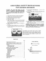
8,
Do Not Grind or Polish Magnesium...
catch on fire.
9.
Note and follow
Safety
Instructions
because it could
that appear
on the
belt guard.
_FTSMRN
1.
General safety Instructions
2.
Getting
3.
Basic Sander/Grinder
4.
Maintenance
5.
Power Source Outlet.
while in use to protect
to Know Your
for Power Tools
Sander/Grinder
Operations
(Page 2)
NOTORIZED
SANDER-GRINDER
(Page 5)
(Page 6)
(Page 8)
This tool
should be grounded
the operator from electric shock,
See "Motor
Specifications
section further on in this
and E lectrical
manual,
Maintain
control
10. THINK
SAFETY:
Safety is a combination
of operator
common
sense and alertness
at all times when
the
Sander/Grinder
is being used,
Requirements"
6.
Support Workpiece.
a|l times,
of workpiece
at
7.
Do Not Wet Grind or Polish. Never use a steady stream
of water on the workpiece.
Only quench the workpiece
in water to cool it,
WARNING:
DO NOT ALLOW
FAMILIARITY
(GAINED
FROM FREQUENT
USE OF YOUR SANDER!GRINDER)
TO BECOME
cOr_MONPLACE,
ALWAYS
REMEMBER
THAT
A CARELESS
FRACTION
OF A SECOND
IS
SUFFICIENT
TO INFLICT
SEVERE
INJURY.
WEAR YOUR
The operation
of any power
tool can result
in foreign
objects
being thrown
into the eyes, which
can result in
severe eye damage. Always
wear safety goggles complying
with ANSI Z87,1 (shown on Package) before commencing
power tool operation.
Safety Goggles are available at Sears
retail or catalog stores.
CONTENTS
Page
General Rules for Power TooUs ...................
Additional Safety Instructions for Sander Grinder
Motor Specifications and Electrical Requirements
Assembly ....................................
Installing Abrasive Belt ......................
Tracking Abrasive Belt
......................
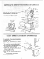
Getting to Know Your Sander/Grinder
.............
Basic Sander/Grinder Operation ..................
Sanding Wood or Plastics .....................
Grinding Metal .............................
Inside Work ...............................
Sharpening ................................
Polishing .................................
Maintenance .................................
Lubrication ..................................
Recommended Accessories ......................
Trouble Shooting ..............................
Repair Parts .................................
2
....
....
3
4
5
5
5
6
6
6
TOOLS NEEDED
9/t6
INCH WRENCH
7
7
8
8
8
8
9
9
10
COMBINATION
SQUARE
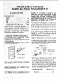
PECmFICATIO NS
LI:REQUi R EM ENTS
The:AC m0tor is a Split Phase nomreversible type, with the
following specifications
-_ =
Horsepower .................................
Voltage ;. ...............
"...................
Ampe:res .. .......
;, :... :, ._:_:.:..i:do :.,.,..
Hertz ;. .......................................
Phase. ........................
1/3
115
......
6
60
Single
WARNING:
IF NOT PROPERLY GROUNDED
THIS
POWER TOOL CAN INCUR THE POTENTIAL HAZARD
OF ELECTRICAL
SHOCK; PARTICULARLY
WHEN
USED IN DAMP LOCATIONS,/
IN PROXIMITY
TO
PLUMBING, OR OUT OF DOORS. IF AN ELECTRICAL
SHOCK OCCURS THERE IS THE POTENTIAL
OF A
SECONDARY
HAZARD
SUCH AS YOUR HANDS
CONTACTING
THE ABRASIVE BELT OR DISC.
This
Rotation (viewed from: Pulleyend); ;:_:;; ;. ;:; clockwise
Abrasive BeltSpeed: (FeeltPer Min:,)ApproXl / :: .;: . .3000
Althodghlthe-motO_:i isdeSigr_ed for o_rat!on
on the
voltage and frequency Specified on m:bt0r nameplate,
normal loads wilt be handled safely on voltages not mere
than 10% abo$e or below 'the nameplate vottage. Heavy
loads; howeVer, require that v01tage at;m0t0r terminals be
not lessthan the Voltage specified on nameplate:
Sander/Grinder
protect the operator
If power
it replaced
must
from
cord is worn
begroundedlWhile
electrical
:in
in any way, have
immediately,
if your Sander/Grinder
is for use on less than: 150 volts
has a plug that looks like below_
3-PRONG
This plug requires
outlet as shown.
If
the
outlet
Sander/Grinder
REMOVE
OR
a mating
you
is of
ALTER
It is recommended
that
replace the TWO prong
THREE prong outlet.
use:to
shoCk.
or cut, or damaged
is equipped
with
a 3-conductor
3-conductor
it
cord
grounded
type
are
planning
to
use for
this
the two
prong type
DO
NOT
THE
GROUNDING
PRONG
iN
ANY
MANNER.
Use an adapter
as shown
connect the grounding lug to a known ground.
CONN ECTING TO: POWER SOURCE O UTLET
This
SandertGrinder
and grounding
type plug which
has a grounding
prong,
approved
by Underwriters
_ Laboratories
and the Canadian
Standards
Association.
The ground conductor
has a green
lug and is attached tO the tool housing at one end and to the
ground prong in the attachment
plug at the other end.
and
you have a qualified
outlet
with a properly
always
electrician
grounded
An adapter as shown below is available for connecting
plugs
to 2-prong receptacles.
The green grounding
lug extending
from the adapter must be connected
to a permanent
ground
such as to a properly grounded outlet box.
GROUNDI NG LUG
PLUG
3-p ONG\
sURE
T.Js,s
I'- :CONNECTED TOA
:I:
e
GI_OUNDING
PRONG
PROPI]RLY GROUNDED
3-PRONG
OUTLET
Plug power
cord into 110-120V
properly
outlet
protected
by a 1S-amp. time delay
fuse or circuit breaker.
grounded
type
or Circuit-Saver
IF YOU ARE NOT SURE THAT YOUR OUTLET
IS
PROPERLY GROUNDED,
HAVE IT CHECKED BY A
QUALIFIED ELECTRICIAN.
......... "
NOTE: The adapter illustrated
is for use only if you already
have a properly
grounded 2-prong
receptacle.
Adapter
is
not allowed in Canada by the Canadian Electrical
Code.
The
use of
any
extension
power.
To
keep this
over-heating
and motor
determine
the minimum
cord
will
cause
some
loss of
to a minimum
and to prevent
burn-out,
use the table below to
wire size (A,W.G.) extension
cord,
Use only
3 wire extension
cords
which
have 3 prong
grounding
type
plugs and 3-pole
receptacles
which
will
accept the plug on the Sander/Grinder.
Extension Cord Length
WARNING:
DO NOT PERMIT FINGERS TO TOUCH
THE TERMINALS
OF PLUG WHEN INSTALLING
OR
REMOVING THE PLUG TO OR FROM THE OUTLET.
RECEPTACLE
Up to 100 Ft.........................
100-200 Ft ...........................
200-400 Ft ............................
Wire Size A.W,G.
16
14
10
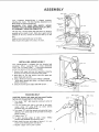
ASSEMBLY
PUSH
DOWN
Your
Craftsman
Sander/Grinder
is shipped complete
including the motor, The Disc Sanding attachment and
Miter Gauge are optional accessories.
WARNING:
FOR
YOUR
OWN SAFETY,
NEVER
CONNECT PLUG TO POWER SOURCE OUTLET UNTIL
ALL ASSEMBLY STEPS ARE COMPLETED.
The top
purposes
pressure
REAR
IDLER
arm is spring
loaded and held down for shipping
with
a piece of cord. Hold down against spring
on the arm, remove the cord and ease up on the
arm,
Apply
a coat of automobile
Wipe all parts thoroughly
PLATEN
wax to the table,
with
a clean,
LOCKING
SCREWS
dry cloth.
LOWER
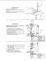
I NSTALLI
NG ABRASIVE
BELT
WING
NUT
Your
Sander!Grinder
is shipped
with
the abrasive
belt
installed.
When
replacing
belts,
notice
directional
arrow
_
on inside of belt..,
it must point downward
on the front section of the belt when installed,
1. Remove both upper and lower
the three (3) wing screws which
belt guards by removing
secure the guards.
2.
Push down on arm and position
lower wheels and rear idler.
3.
Using a 9/16 inch wrench, loosen
• swing table upwards
and move
without
touching
it.
4.
Using an accurate
square
adjust
belt
over
upper
and
TABLE
LOCKNUT.,
it as close to the belt
table 90 ° to belt,,,
TABLE
TRACKING
BELT
BACK GUARD
CAUTION:
Remove both upper and lower guard,
belt may cut into guard prior to final tracking.
1. Turn
motor
upper
"ON".
Belt should
be running
Sanding
in center
of
wheel,
2, If it runs toward
the right or left side of the wheel,
loosen
screw
"'A'"
using
3/t6"
set screw
wrench
furnished
with your Sander/Grinder.
3. Turn
screw
"B"
with
Hex wrench
sideways, Turn screw right
center of wheel.
4.
Tighten
and notice
or left until
belt move
beitt is running
screw "'A',
5. If
belt
touches
edges
of table,
loosen
ADJUSTING
SCREWS and reposition
table,
6. Belt should
be even ,with edges of platen
loosen screws holding platen and adjust it,
7.
Replace
in
"Upper"
and "Lower"
Guards,
TABLE
if it is not,
SCREW "A"
LOCKNUT
UPPER
WHEEL
UB SANDER/GRINDER
UPPER
:::.:
TRACKING
ARM
i
:
:
"'-^o,_W
0,o, 0c,o,,o00,o,,,0
a0<o<
0 o,o
TABLE
LOCK
NUT
locks:table
in place.
Use a square or
:
TRACKING
SCREWS
are adjusted
to track
_
T
_:
_""_ :_
_!_
_
4_"r:..__
'
:
:[
belt.
f_
_ _
h',_'lft
IDLER
IPPER
\_
......
[_//\
"._I
,,i
/UPPER
WHEEL
LOWER
.-.--TRACKING
SCREW
/ARRAS
UPPERI_L/'_E:
_
GUARD
VE BELT
s_--.-_l
(REF.)
FOR
\
:_
REAR
WITH
SCREW
\
SCREWS
2"
,,_LE_._I
Wtl P N_
_._ _"
PLATEN
/
PROVISION
LOCKING
G
--,----,.
_
ER WHEEL
_
PULLEY
BELT
GUARD
AND
_
_
fJ
RUBBER
FEET
BASE
.
_
__
•
BASIC
We
recommend
the
SANDERIGRINDER:
following
your Sander/Grinder
so :that
minimize personal injury.
WARNING:
OBSERVE
FOR
YOUR
FOLLOWING
THE
1, Make sure Table
Lock Nut
instructions
for
operating
you get the best results
and to
OWN
SAFETY,
ALWAYS
SAFETY
PRECAUTIONS.
is always tight.
2, Remove plug from power source outlet when adjusting
table, changing belts, or removing Or adjusting
platen.
3, After turning
switch ON, always allow the
up to full speed before sanding or grinding.
belt to come
4. Make
sure
belt
always
tracks
properly.
Push the
w0rkpiece
or cutting
tool gently
against the belt...
allowing
the belt to cut without
reducing the belt speed
appreciably
or stalling the motor.
5. Keep your
6. Replace
frayed.
hands clear of the belt.
belts
when
SANDING
Move the workpiece
they
become
loaded
WOOD OR PLASTICS
across the belt.
(glazed)
or
OPERATIONS
GRINDING
Move the workpiece
If the workpiece
cold ware r.
across
METAL
the belt.
becomes
too
hot
to handle,
Never push a sharp corner of the workpiece
the belt because the belt could tear.
quench
rapidly
it in
against
INSIDE WORK
WARNINIG: FOR YOUR OWN SAFETY,
FROM POWER SOURCE OUTLET.
1. Remove
2.
Loosen
3.
Remove
both
"Upper"
and "Lower"
wing nut and position
the "Hairpin
Clip"
which
retains
5.
and under
belt
over
lower
opening
wheel
PLATEN
back as shown.
position
belt through
OF
guards.
guard
Use a pair of long nose pliers.
4. Remove
washer and idler, and
underneath
table; replace clip.
Position
BELT ON
BOTH SIDES
REMOVE PLUG
the rear idler,
them
on
idler,
HAIRPIN
/
shaft
Thread
in workpiece.
BELT
IDLER
AND
PLATEN
&
NUT
6.
Push down on arm and position
and over upper wheel.
7.
Make sure upper idler is positioned
to run against platen,
8.
tt
can
be
repositioning
9.
Replace
10. Position
11. Follow
adjusted
idler arm.
"Upper"
guard
by
and tighten
same procedure
so that
loosening
and "Lower"
back
belt around
upper
idler
,o
it causes belt
nut
"'A"
and
guards.
wing
for Sanding
nut.
or Grinding.
7
"A"
)
'!
CLIP
k¸
///
:._
I
SHARPENING
1. Adjust table, to proper angular position for: intended
operation. Cock securely.
2_ When _sharpening short: cutting tools such as wood
chisels; it wii[ be neceSsaW 1_oclamp a piece of wood to:
the table.
3. Sand a notch on the back of the Wood so that the top
corner is close to the belt_
N_ON
//
BACK OF WOOD
4. Move the cutting tool across the belt, pushing on it
gently sotbet it does not burn.
5. Frequently quench the cutting tool in water to keep it
cool.
t
!
I
I
I
I
I
t
POL ISHING
1: RemoVe platen
it to the rear.
and adjust
upper
I
idler as shown or swing
2. Push the workpiece
against the belt,.,
move
that the bett does not come off the wheels.
3. If the workpiece
is metal, frequently
quench
to keep it cool and prevent it from biJrning.
I
!1
qllll
,
rill
it gently
so
it in water
i
III IIII
LUBRiCATiON
MAINTENANCE
WARNING:
REMOVE PLUG FROM POWER SOURCE
OUTLET BEFORE MAINTAINING
OR LUBRICATING
YOUR SANDER/GR INDER.
The upper and lower wheels run on ball bearings which are
permanently
lubricated;
They
require
no
further
lubrication.
Keep the Sander/Grinder and motor clean. Frequently blow
out:duSt and chips.
The
idlers
contain
few drops of light
bronze
machine
bearings,
oi!.
Occasionally
apply
a
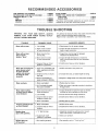
RECOMMENDED
DISC SANDING ATTACHMENT
..............
MITER GAUGE (FOR USE WITH 9-22563) ......
ABRASIVE BE LTS 1" x 42"
FINE ..................................
MEDIUM ...............................
COARSE ...............................
ACCESSORIES
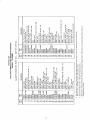
9-22563
9-22574
9-26056
9-26055
9-26054
TROUBLE
WARNING:
REMOVE
BEFORE
FOR
PLUG
YOUR
FROM
TROUBLE
OWN
POWER
i
Motor
SAFETY,
SOURCE
ALWAYS
OUTLET
,H, ,, i
PROBABLE
CAUSE
l iH
Hi i,
will not start.
Hi
9-22219
9-2918
9-2917
The above recommended accessories are current
available at the time this manual was printed.
and were
SHOOTING
Any attempt
to repair the motor may create a hazard
repair is done by qualified
service technician.
Repair service is available at your nearest Sears Store.
SHOOTING.
TROUBLE
ill
STEEL STAND ............................
POWER TOOL KNOW HOW "HANDBOOKS"
TABLE SAW .............................
RADIAL SAW ............................
SUGGESTED
unless
REMEDY
HHJ*_
1. Low voltage.
1.
2,
2. Open circuit in motor
or loose connections.
Check
power
line for proper
voltage.
Inspect all lead terminations
loose or open connection,
on motor
for
,, ,,,,,
Motor will not start,
fuses or circuit
breakers "blow".
1. Short circuit in line,
cord or plug.
t. Inspect line, cord or plug for damaged
insulation
and shorted wires,
2. Short circuit in motor
or loose connections,
2. Inspect alf lead terminations
on motor for
loose or shorted terminals
or worn insulation
on wires.
3. Incorrect
3. Install
breakers
Motor fails to develop full
power (power output
of motor decreases
rapidly with decrease
in voltage at motor
terminals),
t. Power
fuses or circuit
line overloaded
lights, appliances
motors,
overheats.
2. Undersize
with
1. Reduce the toad
on the power
line.
wires or circuits
2. Increase
wire sizes, or reduce
_ength of wiring.
3. General overloading
of
power company's
facilities.
3. Request
a voltage
the power
1. Motor
1. Reduce
overloaded.
1. Short circuit in motor
loose connections.
or
breakers
fuses or circuit
4. Motor
overloaded.
t. Motor
overloaded.
2. incorrect
breakers.
company.
........
load on motor.
to provide
normal
air circulation
1. Inspect terminals
in motor for loose or shorted
terminals
or worn insulation
on lead wires.
2. Correct
in power
check from
_ J,,J
2. Clean out motor
through
motor.
2. Low voltage.
3. Incorrect
Frequent opening of fuses
or circuit breakers.
breakers.
too long.
2. Air Circulation
through
the motor restricted,
Motor stalls (resulting
in blown fuses or tripped
circuit breakers).
fuses or circuit
and other
,
Motor
correct
in powerline.
3. install
the low
correct
line voltage
fuses or circuit
conditions.
breakers,
line.
4. Reduce load on motor.
I. Reduce
fuses or circuit
2. install
motor
correct
load.
fuses or circuit
breakers.
,,,,,,.............
Machine
down
slows
1. "V'"
Belt to loose
1. Adjust belt tension by pushing motor toward
back until al_ slack is removed from belt.
while operating
Abrasive
belt runs
2. Applying to much
pressure to workpiece
2. Ease up on pressure,
1. Not
t, See assembly
tracking
properly,
off top wheel
section
"Track
ing _elt"
I
!
9
10
eO
x
cO
r,.O
O0
:<CO
o
"-_ co
.'Z_ '_-" X _'-... _
0
0
LO
.4'
E
._-..
O2
o
O0
.£
E
"a
E
>
6
n_
c-
z
0
w
r_
UJ
Z
v
t_
m
W
0"_ O0 0'_
0
0
0
n
0
c
0
o
.-_
_6
"o
Z
I
0
6
m
..z n" 00
z
k-
t-
r_
o
E
rr" -- -J
x
0
rr
0
rr"
rr
0
n_
x
0
Ze_x
co
O0
_
.J_
0
Ii
J
_N-_
._
o.-__ _
g.
_5
_z
II
_-_
-o__o
>':
g
g_
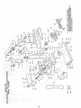
1 UNCH SANDER
SERVICE
MODEL NO.
113.22560
HOW TO ORDER
REPAIR PARTS
Now that you have purchased your 1-inch sander grinder,
should a need ever exist for repair or service, simply contact any
Sears Service Center and most Sears, Roebuck and Co. stores.
Be sure to provide all pertinent facts when you catl or visit.
The model number of your
on the side of the base.
Part No. 68038
lqnch
WHEN ORDERING
REPAIR
FOLLOWING
INFORMATION:
sander grinder will be found
PARTS,
ALWAYS
GiVE
PART NUMBER
PART DESCRIPTION
MODEL NUMBER
113.22560
NAME OF ITEM
I-fNCH SANDER
All parts listed may be
and most Sears stores.
locally, your order will
Repair Parts Distribution
Sold by SEARS,
GRINDER
ROEBUCK
AND
Form
GRINDER
ordered from any Sears Service Center
If the parts you need are not stocked
be electronically
transmitted to a Sears
Center for handling.
CO., Chicago,
No, SP4189-3
THE
tL. 60684
Printed
U.S.A.
in U.S.A.
8/7_