1
TOSHIBA
Telecommunication Systems Division
®
Strata CIX40, CIX100-S, CIX100,
CIX200, CIX670, and CIX1200
General Description
Title Page
August 2014
Publication Information
Toshiba America Information Systems, Inc.
Telecommunication Systems Division
Publication Information
Toshiba America Information Systems, Inc., Telecommunication Systems Division, reserves the right,
without prior notice, to revise this information publication for any reason, including, but not limited to,
utilization of new advances in the state of technical arts or to simply change the design of this document.
Further, Toshiba America Information Systems, Inc., Telecommunication Systems Division, also reserves
the right, without prior notice, to make such changes in equipment design or components as engineering or
manufacturing methods may warrant.
CIX-GD-ALL-VQ
Version Q.2, August 2013
4010487
Our mission to publish accurate, complete and user accessible documentation. At the time of printing the
information in this document was as accurate and current as was reasonably possible. However, in the
time required to print and distribute this manual additions, corrections or other changes may have been
made. To view the latest version of this or other documents please refer to the Toshiba FYI web site.
Toshiba America Information Systems shall not be liable for any commercial losses, loss of revenues or
profits, loss of goodwill, inconvenience, or exemplary, special, incidental, indirect or consequential
damages whatsoever, or claims of third parties, regardless of the form of any claim that may result from the
use of this document.
THE SPECIFICATIONS AND INFORMATION PROVIDED HEREIN ARE FOR INFORMATIONAL
PURPOSES ONLY AND ARE NOT A WARRANTY OF ACTUAL PERFORMANCE, WHETHER
EXPRESSED OR IMPLIED. THE SPECIFICATIONS AND INFORMATION ARE SUBJECT TO CHANGE
WITHOUT NOTICE. ACTUAL PERFORMANCE MAY VARY BASED ON INDIVIDUAL
CONFIGURATIONS, USE OF COLLATERAL EQUIPMENT, OR OTHER FACTORS.
© Copyright 2003~2014
This document is copyrighted by Toshiba America Information Systems, Inc. with all rights reserved. Under
the copyright laws, this document cannot be reproduced in any form or by any means—graphic, electronic,
or mechanical, including recording, taping, photocopying, without prior written permission of Toshiba. No
patent liability is assumed, however, with respect to the use of the information contained herein.
Trademarks
Strata, SmartMedia, SD (Secure Digital) and CIX are registered trademarks of Toshiba Corporation.
Stratagy, eManager, and My Phone Manager are registered trademarks of Toshiba America Information
Systems, Inc.
Windows and Microsoft are registered trademarks of Microsoft.
Trend Micro and PC-cillin are registered trademarks of Trend Micro Inc.
Norton Anti-Virus is a registered trademark of Symantec Corp.
McAfee and Virusscan are registered trademarks of McAfee, Inc.
Trademarks, registered trademarks, and service marks are the property of their respective owners.
Strata CIX General End User Information
The Strata CIX40, CIX100, CIX200, CIX670, and CIX1200 Business Telephone System is registered in
accordance with the provisions of Part 68 of the Federal Communications Commission’s Rules and
Regulations.
FCC Requirements
Means of Connection: The Federal Communications Commission (FCC) has established rules which
permit the Strata CIX system to be connected directly to the telephone network. Connection points are
provided by the telephone company—connections for this type of customer-provided equipment will not be
provided on coin lines. Connections to party lines are subject to state tariffs.
Incidence of Harm: If the system is malfunctioning, it may also be disrupting the telephone network. The
system should be disconnected until the problem can be determined and repaired. If this is not done, the
telephone company may temporarily disconnect service. If possible, they will notify you in advance, but, if
advance notice is not practical, you will be notified as soon as possible. You will be informed of your right to
file a complaint with the FCC.
Service or Repair: For service or repair, contact your local Toshiba telecommunications distributor. To
obtain the nearest Toshiba telecommunications distributor in your area, log onto www.toshiba.com/taistsd/
pages/support_dealerlocator.html or call (800) 222-5805 and ask for a Toshiba Telecom Dealer.
Telephone Network Compatibility: The telephone company may make changes in its facilities, equipment,
operations, and procedures. If such changes affect the compatibility or use of the Strata CIX40, CIX100,
CIX200, CIX670 or CIX1200 system, the telephone company will notify you in advance to give you an
opportunity to maintain uninterrupted service.
Notification of Telephone Company: Before connecting a Strata CIX system to the telephone network, the
telephone company may request the following:
1.Your telephone number.
2.FCC and ACTA registration
• Strata CIX40, CIX100, CIX200, CIX670 or CIX1200 may be configured as a Key, Hybrid or PBX
telephone system. The appropriate configuration for your system is dependent upon your operation of
the system.
• If the operation of your system is only manual selection of outgoing lines, it may be registered as a Key
telephone system.
• If your operation requires automatic selection of outgoing lines, such as dial access, Least Cost
Routing, Pooled Line Buttons, etc., the system must be registered as a Hybrid telephone system. In
addition to the above, certain features (tie Lines, Off-premises Stations, etc.) may also require Hybrid
telephone system registration in some areas.
• If you are unsure of your type of operation and/or the appropriate FCC registration number, contact
your local Toshiba telecommunications distributor for assistance.
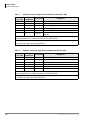
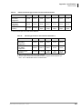
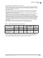
SYSTEM
CIX40
CIX100,
CIX670 and
CIX1200
CIX200
PBX
Fully-protected PBXs
FCC Registration Numbers
Hybrid
Fully-protected multifunction systems
KEY
Fully-protected telephone key systems
CJ6-PF03BDTCHS402 CJ6-MF03BDTCHS402
CJ6-MUL-35931-PF-E CJ6-MUL-35930-MF-E
CJ6-KD03BDTCHS402
CJ6-MUL-35929-KF-E
CJ6-PF03BDTCHS192 CJ6-MF03BDTCHS192
CJ6-KD03BDTCHS192
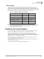
• Ringer equivalence number: 0.3B. The ringer equivalence number (REN) is useful to determine the
quantity of devices which you may connect to your telephone line and still have all of those devices
ring when your number is called. In most areas, but not all, the sum of the RENs of all devices
connected to one line should not exceed five (5.0B). To be certain of the number of devices you may
connect to your line, as determined by the REN, you should contact your local telephone company to
ascertain the maximum REN for your calling area.
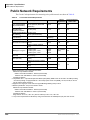
3.Network connection information USOC jack required: RJ11/14C,
RJ21/2E/2F/2G/2HX/RJ49C (see Network Requirements in this document). Items 2, 3 and 4 are also
indicated on the equipment label.
4.Authorized Network Parts: 02LS2/GS2, 02RV2-T/O, OL13C/B, T11/12/31/32M, 04DU9-BN/DN/1SN,
02IS5, 04DU9-BN/DN/1SN1ZN
Radio Frequency Interference
Warning: This equipment generates, uses, and can radiate radio frequency energy and if not installed and
used in accordance with the manufacturer’s instruction manual, may cause interference to radio
communications. It has been tested and found to comply with the limits for a Class A computing device
pursuant to Subpart J of Part 15 of FCC Rules, which are designed to provide reasonable protection
against such interference when operated in a commercial environment. Operation of this equipment in a
residential area is likely to cause interference, in which case, the user, at his/her own expense, will be
required to take whatever measures may be required to correct the interference.
Underwriters Laboratory
This system is listed with Underwriters Laboratory (UL). Secondary protection is required, on
any wiring from any telephone that exits the building or is subject to lightning or other electrical
surges, and on DID, OPS, and Tie lines. (Additional information is provided in this manual.)
49L7
I.T.E
Important Notice — Music-On-Hold
In accordance with U.S. Copyright Law, a license may be required from the American Society of
Composers, Authors and Publishers, or other similar organization, if radio or TV broadcasts are
transmitted through the music-on-hold feature of this telecommunication system. Toshiba America
Information Systems, Inc., strongly recommends not using radio or television broadcasts and hereby
disclaims any liability arising out of the failure to obtain such a license.
CP01, Issue 8, Part I Section 14.1
Notice: The Industry Canada label identifies certified equipment. This certification means that the
equipment meets certain telecommunications network protective, operational and safety requirements as
prescribed in the appropriate Terminal Equipment Technical Requirements document(s). The Department
does not guarantee the Equipment will operate to the user’s satisfaction.
Before installing this equipment, users should ensure that it is permissible to be connected to the facilities
of the local telecommunications company. The equipment must also be installed using an acceptable
method of connection. The customer should be aware that compliance with the above conditions may not
prevent degradation of service in some situations.
Repairs to certified equipment should be coordinated by a representative designated by the supplier. Any
repairs or alterations made by the user to this equipment, or equipment malfunctions, may give the
telecommunications company cause to request the user to disconnect the equipment.
Users should ensure for their own protection that the electrical ground connections of the power utility,
telephone lines and internal metallic water pipe system, if present, are connected together. This precaution
may be particularly important in rural areas.
CAUTION!
Users should not attempt to make such connections themselves, but should
contact the appropriate electric inspection authority, or electrician, as appropriate.
CP01, Issue 8, Part I Section 14.2
Ringer Equivalence Notice: The Ringer Equivalence Number (REN) assigned to each terminal device
provides an indication of the maximum number of terminals allowed to be connected to a telephone
interface. The terminal on an interface may consist of any combination of devices subject only to the
requirement that the sum of the Ringer Equivalence Numbers of all the Devices does not exceed 5.
Hearing Aid Compatibility Notice: The FCC has established rules that require all installed business
telephones be hearing aid compatible. This rule applies to all telephones regardless of the date of
manufacture or installation. There are severe financial penalties which may be levied on the end-user for
non-compliance.
Patent Marking for G.729a
Products may be covered by one or more of the following US patents and their counterparts in other
countries:
US5,787,391, US5,717,825, US5,708,757, US5,754,976, US5,701,392, US5,699,482, US5,444,816
MPEG-4 VISUAL PATENT PORTFOLIO LICENSE (for VCS)
"THIS PRODUCT IS LICENSED UNDER THE MPEG-4 VISUAL PATENT PORTFOLIO LICENSE FOR
THE PERSONAL AND NON-COMMERCIAL USE OF A CONSUMER FOR (i)ENCODING VIDEO IN
COMPLIANCE WITH THE MPEG-4 VISUAL STANDARD ("MPEG-4 VIDEO") AND/OR (ii)DECODING
MPEG-4 VIDEO THAT WAS ENCODED BY A CONSUMER ENGAGED IN A PERSONAL AND NONCOMMERCIAL ACTIVITY AND/OR WAS OBTAINED FROM A VIDEO PROVIDER LICENSED BY MPEG
LA TO PROVIDE MPEG-4 VIDEO. NO LICENSE IS GRANTED OR SHALL BE IMPLIED FOR ANY
OTHER USE. ADDITIONAL INFORMATION INCLUDING THAT RELATING TO PROMOTIONAL,
INTERNAL AND COMMERCIAL USES AND LICENSING MAY BE OBTAINED FROM MPEG LA,L.L.C.
SEE HTTP://WWW.MPEGLA.COM"
TOSHIBA AMERICA INFORMATION SYSTEMS, INC. (“TAIS”)
Telecommunication Systems Division License Agreement
IMPORTANT: THIS LICENSE AGREEMENT (“AGREEMENT”) IS A LEGAL AGREEMENT BETWEEN YOU (“YOU”) AND TAIS. CAREFULLY READ THIS LICENSE AGREEMENT. USE OF ANY
SOFTWARE OR ANY RELATED INFORMATION (COLLECTIVELY, “SOFTWARE”) INSTALLED ON OR SHIPPED WITH A TAIS DIGITAL SOLUTIONS PRODUCT OR OTHERWISE MADE AVAILABLE TO
YOU BY TAIS IN WHATEVER FORM OR MEDIA, WILL CONSTITUTE YOUR ACCEPTANCE OF THESE TERMS, UNLESS SEPARATE TERMS ARE PROVIDED BY THE SOFTWARE SUPPLIER. IF
YOU DO NOT AGREE WITH THE TERMS OF THIS LICENSE AGREEMENT, DO NOT INSTALL, COPY OR USE THE SOFTWARE AND PROMPTLY RETURN IT TO THE LOCATION FROM WHICH YOU
OBTAINED IT IN ACCORDANCE WITH APPLICABLE RETURN POLICIES. EXCEPT AS OTHERWISE AUTHORIZED IN WRITING BY TAIS, THIS SOFTWARE IS LICENSED FOR DISTRIBUTION
THROUGH TAIS AUTHORIZED CHANNELS ONLY TO END-USERS PURSUANT TO THIS LICENSE AGREEMENT.
1. License Grant. The Software is not sold; it is licensed upon payment of applicable charges. TAIS grants to you a personal, non-transferable and non-exclusive right to use the copy of the Software
provided under this License Agreement. You agree you will not copy the Software except as necessary to use it on one TAIS system at a time at one location. Modifying, translating, renting, copying,
distributing, printing, sublicensing, transferring or assigning all or part of the Software, or any rights granted hereunder, to any other persons and removing any proprietary notices, labels or marks from the
Software is strictly prohibited except as permitted by applicable law; you agree violation of such restrictions will cause irreparable harm to TAIS and provide grounds for injunctive relief, without notice,
against you or any other person in possession of the Software. You and any other person whose possession of the software violates this License Agreement shall promptly surrender possession of the
Software to TAIS, upon demand. Furthermore, you hereby agree not to create derivative works based on the Software. TAIS reserves the right to terminate this license and to immediately repossess the
software in the event that you or any other person violates this License Agreement. Execution of the Software for any additional capabilities require a valid run-time license.
2. Intellectual Property. You acknowledge that no title to the intellectual property in the Software is transferred to you. You further acknowledge that title and full ownership rights to the Software will remain
the exclusive property of TAIS and/or its suppliers, and you will not acquire any rights to the Software, except the license expressly set forth above. You will not remove or change any proprietary notices
contained in or on the Software. The Software is protected under US patent, copyright, trade secret, and/or other proprietary laws, as well as international treaties. Any transfer, use, or copying of the
software in violation of the License Agreement constitutes copyright infringement. You are hereby on notice that any transfer, use, or copying of the Software in violation of this License Agreement constitutes
a willful infringement of copyright.
3. No Reverse Engineering. You agree that you will not attempt, and if you employ employees or engage contractors, you will use your best efforts to prevent your employees and contractors from
attempting to reverse compile, reverse engineer, modify, translate or disassemble the Software in whole or in part. Any failure to comply with the above or any other terms and conditions contained herein
will result in the automatic termination of this license and the reversion of the rights granted hereunder back to TAIS.
4. Limited Warranty. THE SOFTWARE IS PROVIDED “AS IS” WITHOUT WARRANTY OF ANY KIND. TO THE MAXIMUM EXTENT PERMITTED BY APPLICABLE LAW, TAIS AND ITS SUPPLIERS
DISCLAIM ALL WARRANTIES WITH REGARD TO THE SOFTWARE, EITHER EXPRESS OR IMPLIED, INCLUDING, BUT NOT LIMITED TO, THE WARRANTY OF NON-INFRINGEMENT OF THIRD
PARTY RIGHTS, THE WARRANTY OF YEAR 2000 COMPLIANCE, AND THE IMPLIED WARRANTIES OF MERCHANTABILITY AND FITNESS FOR A PARTICULAR PURPOSE. THE ENTIRE RISK AS
TO THE QUALITY AND PERFORMANCE OF THE SOFTWARE IS WITH YOU. NEITHER TAIS NOR ITS SUPPLIERS WARRANT THAT THE FUNCTIONS CONTAINED IN THE SOFTWARE WILL MEET
YOUR REQUIREMENTS OR THAT THE OPERATION OF THE SOFTWARE WILL BE UNINTERRUPTED OR ERROR-FREE. HOWEVER, TAIS WARRANTS THAT ANY MEDIA ON WHICH THE
SOFTWARE IS FURNISHED IS FREE FROM DEFECTS IN MATERIAL AND WORKMANSHIP UNDER NORMAL USE FOR A PERIOD OF NINETY (90) DAYS FROM THE DATE OF DELIVERY TO
YOU.
5. Limitation Of Liability. TAIS’ ENTIRE LIABILITY AND YOUR SOLE AND EXCLUSIVE REMEDY UNDER THIS LICENSE AGREEMENT SHALL BE AT TAIS’ OPTION REPLACEMENT OF THE MEDIA OR
REFUND OF THE PRICE PAID. TO THE MAXIMUM EXTENT PERMITTED BY APPLICABLE LAW, IN NO EVENT SHALL TAIS OR ITS SUPPLIERS BE LIABLE TO YOU FOR ANY CONSEQUENTIAL,
SPECIAL, INCIDENTAL OR INDIRECT DAMAGES FOR PERSONAL INJURY, LOSS OF BUSINESS PROFITS, BUSINESS INTERRUPTION, LOSS OF BUSINESS INFORMATION/DATA, OR ANY
OTHER PECUNIARY LOSS OF ANY KIND ARISING OUT OF THE USE OR INABILITY TO USE THE SOFTWARE, EVEN IF TAIS OR ITS SUPPLIER HAS BEEN ADVISED OF THE POSSIBILITY OF
SUCH DAMAGES. IN NO EVENT SHALL TAIS OR ITS SUPPLIERS BE LIABLE FOR ANY CLAIM BY A THIRD PARTY.
6. State/Jurisdiction Laws. SOME STATES/JURISDICTIONS DO NOT ALLOW THE EXCLUSION OF IMPLIED WARRANTIES OR LIMITATIONS ON HOW LONG AN IMPLIED WARRANTY MAY LAST, OR
THE EXCLUSION OR LIMITATION OF INCIDENTAL OR CONSEQUENTIAL DAMAGES, SO SUCH LIMITATIONS OR EXCLUSIONS MAY NOT APPLY TO YOU. THIS LIMITED WARRANTY GIVES YOU
SPECIFIC RIGHTS AND YOU MAY ALSO HAVE OTHER RIGHTS WHICH VARY FROM STATE/JURISDICTION TO STATE/JURISDICTION.
7. Export Laws. This License Agreement involves products and/or technical data that may be controlled under the United States Export Administration Regulations and may be subject to the approval of the
United States Department of Commerce prior to export. Any export, directly or indirectly, in contravention of the United States Export Administration Regulations, or any other applicable law, regulation or
order, is prohibited.
8. Governing Law. This License Agreement will be governed by the laws of the State of California, United States of America, excluding its conflict of law provisions.
9. United States Government Restricted Rights. The Software is provided with Restricted Rights. The Software and other materials provided hereunder constitute Commercial Computer Software and
Software Documentation and Technical Data related to Commercial Items. Consistent with F.A.R. 12.211 and 12.212 they are licensed to the U.S. Government under, and the U.S. Government’s rights
therein are restricted pursuant to, the vendor’s commercial license.
10. Severability. If any provision of this License Agreement shall be held to be invalid, illegal or unenforceable, the validity, legality and enforceability of the remaining provisions hereof shall not in any way
be affected or impaired.
11. No Waiver. No waiver of any breach of any provision of this License Agreement shall constitute a waiver of any prior, concurrent or subsequent breach of the same or any other provisions hereof, and no
waiver shall be effective unless made in writing and signed by an authorized representative of the waiving party.
12. Supplier Software. The Software may include certain software provided by TAIS suppliers. In such event, you agree that such supplier may be designated by TAIS as a third party beneficiary of TAIS with
rights to enforce the Agreement with respect to supplier’s software.
YOU ACKNOWLEDGE THAT YOU HAVE READ THIS LICENSE AGREEMENT AND THAT YOU UNDERSTAND ITS PROVISIONS. YOU AGREE TO BE BOUND BY ITS TERMS AND CONDITIONS. YOU
FURTHER AGREE THAT THIS LICENSE AGREEMENT CONTAINS THE COMPLETE AND EXCLUSIVE AGREEMENT BETWEEN YOU AND TAIS AND SUPERSEDES ANY PROPOSAL OR PRIOR
AGREEMENT, ORAL OR WRITTEN, OR ANY OTHER COMMUNICATION RELATING TO THE SUBJECT MATTER OF THIS LICENSE AGREEMENT.
Toshiba America Information Systems, Inc.
Telecommunication Systems Division
9740 Irvine Boulevard
Irvine, California 92618-1697
United States of America
DSD 020905
5932
T
Toshiba America Information Systems, Inc.
Telecommunication Systems Division
End-User Limited Warranty
Toshiba America Information Systems, Inc., (“TAIS”) warrants that this telephone equipment manufactured by
Toshiba (except for fuses, lamps, and other consumables) will, upon delivery by TAIS or an authorized TAIS
dealer to a retail customer in new condition, be free from defects in material and workmanship for twenty-four (24)
months after delivery, except as otherwise provided by TAIS in the TAIS warranty accompanying the products or
posted on TAIS’s website. Products which are not manufactured by Toshiba but are purchased from Toshiba, will
be subject to the warranty provisions provided by the equipment manufacturer, unless TAIS notifies the end-user
of any additional warranty provisions in writing.
This warranty is void (a) if the equipment is used under other than normal use and maintenance conditions, (b) if
the equipment is modified or altered, unless the modification or alteration is expressly authorized by TAIS, (c) if
the equipment is subject to abuse, neglect, lightning, electrical fault, or accident, (d) if the equipment is repaired
by someone other than TAIS or an authorized TAIS dealer, (e) if the equipment’s serial number is defaced or missing, or (f) if the equipment is installed or used in combination or in assembly with products not supplied by TAIS
and which are not compatible or are of inferior quality, design, or performance.
The sole obligation of TAIS or Toshiba Corporation under this warranty, or under any other legal obligation with
respect to the equipment, is the repair or replacement of such defective or missing parts as are causing the malfunction by TAIS or its authorized dealer with new or refurbished parts (at their option). If TAIS or one of its authorized dealers does not replace or repair such parts, the retail customer’s sole remedy will be a refund of the price
charged by TAIS to its dealers for such parts as are proven to be defective, and which are returned to TAIS through
one of its authorized dealers within the warranty period and no later than thirty (30) days after such malfunction,
whichever first occurs.
Under no circumstances will the retail customer or any user or dealer or other person be entitled to any direct,
special, indirect, consequential, or exemplary damages, for breach of contract, tort, or otherwise. Under no circumstances will any such person be entitled to any sum greater than the purchase price paid for the item of equipment
that is malfunctioning.
To obtain service under this warranty, the retail customer must bring the malfunction of the machine to the attention of one of TAIS’ authorized dealers within the applicable warranty period and no later than thirty (30) days
after such malfunction, whichever first occurs. Failure to bring the malfunction to the attention of an authorized
TAIS dealer within the prescribed time results in the customer being not entitled to warranty service.
THERE ARE NO OTHER WARRANTIES FROM EITHER TOSHIBA AMERICA INFORMATION SYSTEMS,
INC., OR TOSHIBA CORPORATION WHICH EXTEND BEYOND THE FACE OF THIS WARRANTY. ALL
OTHER WARRANTIES, EXPRESS OR IMPLIED, INCLUDING THE WARRANTIES OF MERCHANTABILITY,
FITNESS FOR A PARTICULAR PURPOSE, AND FITNESS FOR USE, ARE EXCLUDED.
No TAIS dealer and no person other than an officer of TAIS may extend or modify this warranty. No such modification or extension is effective unless it is in writing and signed by the Vice President and General Manager, Telecommunication Systems Division.
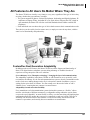
WARRANTIES FOR NON-TOSHIBA BRANDED THIRD
PARTY PRODUCTS
A valuable element of Toshiba’s product strategy is to offer our customers a complete product portfolio. To
provide this value to our customers at the most optimal prices, we offer both Toshiba-branded and thirdparty manufactured products that support our Toshiba Strata CIX product portfolio. Similar to other
resellers of software, hardware and peripherals, these third-party manufactured products carry warranties
independent of our Toshiba limited warranty provided with our Toshiba-branded products. Customers
should note that third-party manufacturer warranties vary from product to product and are covered by the
warranties provided through the original manufacturer and passed on intact to the purchaser by Toshiba.
Customers should consult their product documentation for third-party warranty information specific to thirdparty products. More information may also be available in some cases from the manufacturer’s public
website.
While Toshiba offers a wide selection of software, hardware and peripheral products, we do not specifically
test or guarantee that the third-party products we offer work under every configuration with any or all of the
various models of the Toshiba Strata CIX. Toshiba does not endorse, warrant nor assume any liability in
connection with such third party products or services. If you have questions about compatibility, we
recommend and encourage you to contact the third-party software, hardware and peripheral product
manufacturer directly.
Contents
Introduction
Organization .......................................................................................................................................... ix
Conventions ............................................................................................................................................ x
Related Documents/Media .................................................................................................................... xi
Chapter 1 – Strata CIX Overview
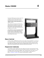
Chapter 2 – Strata CIX40
Processor ................................................................................................................................................ 4
CIX40 Cabinet Slots .............................................................................................................................. 5
Large Scale Integrated (LSI) Circuits (no licenses required) .......................................................... 5
GCTU2A Processor Interfaces ........................................................................................................ 6
GVPH – Integrated Voice Mail .............................................................................................................. 7
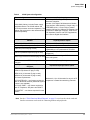
Feature Compatibility ............................................................................................................................. 7
System Configuration ............................................................................................................................. 8
Reserve Power ............................................................................................................................... 11
Telephone and Console Support .......................................................................................................... 11
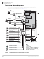
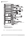
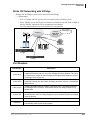
CIX40 Functional Block Diagram ....................................................................................................... 12
Additional Specifications .................................................................................................................... 13
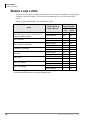
Station Loop Limits .............................................................................................................................. 14
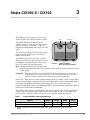
Chapter 3 – Strata CIX100-S / CIX100
CIX100-S and CIX100 Processors ....................................................................................................... 16
CPU/Memory ................................................................................................................................. 16
Large Scale Integrated (LSI) Circuits ............................................................................................ 16
Memory Protection Battery ........................................................................................................... 16
Relay Control Interface ................................................................................................................. 16
External Page Interface .................................................................................................................. 16
Music-on-hold/Background Music Interface ................................................................................. 16
Secure Digital Memory ................................................................................................................ 16
Built-in Ethernet Connection ......................................................................................................... 17
CIX100 Processor Optional Subassemblies .................................................................................. 17
CIX100 Cabinet Slots .......................................................................................................................... 17
Base Cabinet .................................................................................................................................. 17
Expansion Cabinets ....................................................................................................................... 17
Chapter 4 – Strata CIX200
Base Cabinet ......................................................................................................................................... 19
Expansion Cabinets .............................................................................................................................. 19
Basic Specifications ............................................................................................................................. 20
Strata CIX General Description
08/14
1
Contents
Chapter 5 – Strata CIX670 and CIX1200
Power Backup ...................................................................................................................................... 20
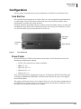
Configuration ....................................................................................................................................... 21
Card Slot Use ................................................................................................................................. 21
Power Factor .................................................................................................................................. 21
CIX200 PCBs ....................................................................................................................................... 22
PCB Option Considerations ........................................................................................................... 22
Common Control Processor Unit (LCTU) .................................................................................... 22
Analog Standard Station Interface Unit (LSLU1A) ...................................................................... 23
Modular or Amphenol Connections ..................................................................................................... 23
Extenders ....................................................................................................................................... 23
Chapter 5 – Strata CIX670 and CIX1200
Strata CIX670 ....................................................................................................................................... 25
CIX670 Processor Circuit Cards .......................................................................................................... 26
CPU/Memory ................................................................................................................................. 26
Large-scale Integrated (LSI) circuits ............................................................................................. 26
Memory Protection Battery ........................................................................................................... 26
Music-on-hold/Background Music Interface ................................................................................. 26
Secure Digital (SD) Memory ......................................................................................................... 26
Network Interface .......................................................................................................................... 27
CIX670 Processor Optional Subassemblies .................................................................................. 27
Strata CIX1200 ..................................................................................................................................... 28
CIX1200 Processor Circuit Cards ........................................................................................................ 29
CPU/Memory ................................................................................................................................. 29
Large-scale Integrated (LSI) circuits ............................................................................................. 29
Memory Protection Battery ........................................................................................................... 29
Music-on-hold/Background Music Interface ................................................................................. 29
Secure Digital (SD) Memory ......................................................................................................... 29
Network Interface .......................................................................................................................... 30
CIX1200 Processor Optional Subassemblies ................................................................................ 30
CIX670 and CIX1200 Cabinet Slots .................................................................................................... 31
Base Cabinet .................................................................................................................................. 31
Expansion Cabinets ....................................................................................................................... 31
Strata CIX670 and CIX1200 Rack Mount .......................................................................................... 32
Basic Specifications ....................................................................................................................... 32
Base Cabinet .................................................................................................................................. 33
Expansion cabinet .......................................................................................................................... 33
CIX670 and CIX1200 Remote Expansion Cabinet ............................................................................. 34
Chapter 6 – Universal Slot Circuit Cards
Station, Line and Option Circuit Cards ................................................................................................ 35
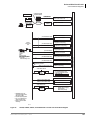
Functional Block Diagrams .................................................................................................................. 40
Chapter 7 – Telephones and Peripherals
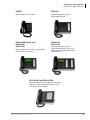
DP5000-series Digital Telephones ....................................................................................................... 45
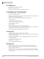
The DP5000 Look ......................................................................................................................... 48
Large Display Area for Call Information ...................................................................................... 48
LCD Key-Strip .............................................................................................................................. 48
Backlight LCD ............................................................................................................................... 48
2
Strata CIX General Description
08/14
Contents
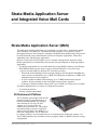
Chapter 8 – Strata Media Application Server and Integrated Voice Mail Cards
Mic Mute ....................................................................................................................................... 49
Handset/Headset ............................................................................................................................ 49
Shift and Hist Keys ........................................................................................................................ 49
Speaker Off-hook Call Announce (DOCA-1A) ............................................................................ 49
DP5000-Series Telephone Tilt Angles .......................................................................................... 50
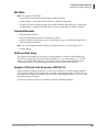
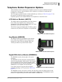
Telephone Button Expansion Options ................................................................................................. 51
LCD Add-on -Module (LM5110) .................................................................................................. 51
Key Module (KM5020) ................................................................................................................. 51
Digital DSS Add on Module (DDM5060) .................................................................................... 51
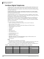
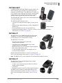
Cordless Digital Telephones ................................................................................................................ 52
DKT2404-DECT ........................................................................................................................... 53
DKT2204-CT ................................................................................................................................. 53
DKT2304-CT ................................................................................................................................. 53
IP4100 DECT Telephone ..................................................................................................................... 54
Handset Features ............................................................................................................................ 54
IP4100-BASE Features .................................................................................................................. 54
IP 5000-Series IP Telephones .............................................................................................................. 55
Features .......................................................................................................................................... 57
IP Protocol ..................................................................................................................................... 57
Connectivity ................................................................................................................................... 57
Capabilities .................................................................................................................................... 58
Liquid Crystal Display (LCD) Models .......................................................................................... 59
Telephone Button Expansion Options ................................................................................................. 60
LCD Add-on Module (LM5110) ................................................................................................... 60
Key Module (KM5020) ................................................................................................................. 60
IP Direct Station Selection (IDM5060) Console ........................................................................... 60
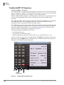
CIX Attendant Console ........................................................................................................................ 61
Peripherals ............................................................................................................................................ 64
Door Phone (MDFB) ..................................................................................................................... 64
Door Phone/Lock Control Unit (DDCB) ....................................................................................... 64
External Speaker (BESCB) ........................................................................................................... 64
Mobility Solutions ................................................................................................................................ 65
SoftIPT ........................................................................................................................................... 65
Wireless Access Points .................................................................................................................. 65
VPN/Firewall Solutions from SonicWALL .................................................................................. 66
Power-Over-Ethernet Solutions from SMC .................................................................................. 66
Video Communication Solution ........................................................................................................... 67
Visual Collaboration ...................................................................................................................... 67
Try VCS for FREE ........................................................................................................................ 67
VCS Features ................................................................................................................................. 67
Software ........................................................................................................................................ 68
VCS Software Upgrade ................................................................................................................. 68
Licenses ......................................................................................................................................... 68
Product Specifications ................................................................................................................69
Toshiba Stratagy Voice Processing ...................................................................................................... 70
Cabling and Connectors ....................................................................................................................... 71
Chapter 8 – Strata Media Application Server and Integrated Voice Mail Cards
Strata Media Application Server (MAS) .............................................................................................. 73
Strata CIX General Description
08/14
3
Contents
Chapter 9 – IPedge Application Server for Strata CIX
2U Rackmount Platform ................................................................................................................ 73
MicroMAS ..................................................................................................................................... 74
Standard Software Applications .................................................................................................... 74
Optional Software Applications .................................................................................................... 75
Connection to the Strata CIX ......................................................................................................... 75
Preloaded Software .............................................................................................................................. 76
Windows XP Firewall Settings ...................................................................................................... 76
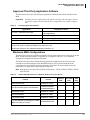
MAS Configuration Requirements ...................................................................................................... 76
Approved Third Party Application Software ................................................................................. 77
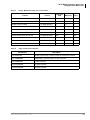
Maximum MAS Configurations .................................................................................................... 77
MAS Licensing .................................................................................................................................... 80
MAS Recovery ..................................................................................................................................... 81
MAS Software Backup .................................................................................................................. 81
MAS Modem (Optional) ...................................................................................................................... 81
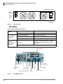
Input Power .......................................................................................................................................... 82
Power Failure Backup ................................................................................................................... 82
Grounding ...................................................................................................................................... 82
Connection ..................................................................................................................................... 82
Physical Specifications ......................................................................................................................... 83
Basic MAS Specifications ............................................................................................................. 83
MicroMAS ..................................................................................................................................... 84
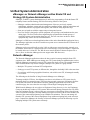
Unified Communications ..................................................................................................................... 85
Unified System Administration ............................................................................................................ 87
eManager® or Network eManager unifies Strata CIX and Stratagy ES System Administration . 87
Network eManager ........................................................................................................................ 87
My Phone Manager Gives Telephone Programming to Individual End-Users ............................. 88
All Features to All Users No Matter Where They Are ........................................................................ 89
FeatureFlex Next Generation Adaptability .................................................................................... 89
LVMU1A Voice Mail Card ................................................................................................................. 92
Features .......................................................................................................................................... 92
Licenses ......................................................................................................................................... 92
Software ......................................................................................................................................... 92
Port Upgrades ................................................................................................................................ 93
GVPH1A Voice Mail Card .................................................................................................................. 93
Other Voice Processing Systems ......................................................................................................... 93
Chapter 9 – IPedge Application Server for Strata CIX
IPedge App Server Solution ................................................................................................................. 96
Messaging ............................................................................................................................................ 97
Automated Attendant ..................................................................................................................... 97
Fax ................................................................................................................................................. 98
Voice Messaging ........................................................................................................................... 99
Unified Messaging ....................................................................................................................... 105
Multi-site Networking ................................................................................................................. 106
Administration ............................................................................................................................. 106
Reporting ..................................................................................................................................... 108
Messaging Survivability .............................................................................................................. 110
Security ........................................................................................................................................ 110
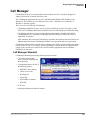
Call Manager ...................................................................................................................................... 111
4
Strata CIX General Description
08/14
Contents
Chapter 10 – VIPedge Application Service for Strata CIX
Call Manager Standard ................................................................................................................ 111
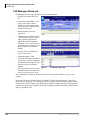
Call Manager Advanced .............................................................................................................. 112
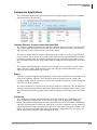
Companion Applications ............................................................................................................. 113
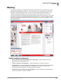
Meeting .............................................................................................................................................. 115
Audio Conference Features ......................................................................................................... 115
Web Collaboration Features ........................................................................................................ 116
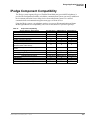
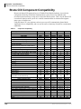
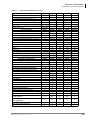
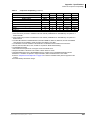
IPedge Component Compatibility ...................................................................................................... 117
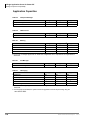
Application Capacities ................................................................................................................. 118
Part Numbers ...................................................................................................................................... 119
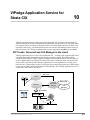
Chapter 10 – VIPedge Application Service for Strata CIX
SIP Trunks, Voicemail and Call Manager in the cloud ............................................................... 121
Strata CIX Networking with VIPedge ......................................................................................... 123
Part Numbers ............................................................................................................................... 123
Chapter 11 – Features
Account Codes ................................................................................................................................... 125
Add-on Module (ADM) ..................................................................................................................... 125
Advisory Messages ............................................................................................................................ 125
Alarm Notification ............................................................................................................................. 126
Alternate Answer Point ...................................................................................................................... 126
Automatic Busy Redial ...................................................................................................................... 126
Automatic Call Distribution (ACD) Server ....................................................................................... 126
Basic ACD Features .................................................................................................................... 127
Enhanced ACD Features ............................................................................................................. 127
Automatic Callback (ACB) ................................................................................................................ 128
Automatic Line Selection ................................................................................................................... 128
Automatic Release ............................................................................................................................. 129
Automatic Release from Hold ..................................................................................................... 129
Automatic Release of Incoming Calls ......................................................................................... 129
Station Automatic Release ........................................................................................................... 129
Background Music (BGM) ................................................................................................................ 129
Call Completion ................................................................................................................................. 129
Call Forward ....................................................................................................................................... 130
Station Call Forward .................................................................................................................... 130
System Call Forward ................................................................................................................... 130
Call Forward Conditions ............................................................................................................. 131
Call Forward Destination ............................................................................................................. 131
Call Forward – Call Types ........................................................................................................... 131
Call Forward Remote ................................................................................................................... 131
Call History ........................................................................................................................................ 132
Call Monitoring and Transfer ............................................................................................................. 132
Call Park ............................................................................................................................................. 133
Call Park Orbits ........................................................................................................................... 133
Park and Page .............................................................................................................................. 133
Call Pickup ......................................................................................................................................... 133
Call Waiting ....................................................................................................................................... 134
Caller Identification ........................................................................................................................... 135
ISDN Calling ID Name and Number .......................................................................................... 135
Strata CIX General Description
08/14
5
Contents
Chapter 11 – Features
Camp on Busy .................................................................................................................................... 135
Automatic Camp On .................................................................................................................... 135
Off-hook Camp On ...................................................................................................................... 136
Cancel Button ..................................................................................................................................... 136
Centrex/PBX Compatible ................................................................................................................... 136
Centrex Ringing Repeat ..................................................................................................................... 136
Classes of Service (COS) ................................................................................................................... 137
Computer Telephony Integration (CTI) ............................................................................................. 137
Conference Calls ................................................................................................................................ 137
Conference On-Hold .................................................................................................................... 137
Join Button ................................................................................................................................... 137
Split/Join/Drop ............................................................................................................................. 137
Releasing from Conference Tandem CO Line Connections ....................................................... 138
Voice Mail Conference ................................................................................................................ 138
Continuous DTMF Tone .................................................................................................................... 138
Credit Card Calling ............................................................................................................................ 138
Data Privacy ....................................................................................................................................... 138
Day/Night Mode – Auto Schedule ..................................................................................................... 139
Delayed Ringing ................................................................................................................................. 140
Destination (Toll) Restriction ............................................................................................................ 140
Through Dialing .......................................................................................................................... 140
Dial Directory ..................................................................................................................................... 140
Direct Inward Dialing (DID) .............................................................................................................. 141
Dialed Number Identification Service (DNIS) .................................................................................. 141
Digital Pad .......................................................................................................................................... 142
Direct Inward System Access (DISA) ............................................................................................... 142
Directory Numbers ............................................................................................................................. 143
Primary [DN] Buttons ................................................................................................................. 143
Phantom [DN] Buttons ................................................................................................................ 143
Pilot [DN] .................................................................................................................................... 143
Distinctive LED Indicator .................................................................................................................. 143
Distinctive Ringing ............................................................................................................................ 144
Do Not Disturb (DND) ....................................................................................................................... 144
Direct Station Selection (DSS) Buttons ............................................................................................. 144
[DSS] Button Status Display ....................................................................................................... 144
DTMF Receivers ................................................................................................................................ 145
DTMF Back Tone ........................................................................................................................ 145
DTMF and Dial Pulse CO Line Compatibility ............................................................................ 145
DTMF Signal Time ..................................................................................................................... 145
Emergency Call .................................................................................................................................. 145
Feature Prompting with Soft Keys ..................................................................................................... 145
Enhanced E911 ................................................................................................................................... 146
External Amplified Speaker ............................................................................................................... 146
Flash Button ....................................................................................................................................... 146
Flexible Line Ringing ........................................................................................................................ 147
Flexible Numbering ........................................................................................................................... 147
Handsfree Answerback ...................................................................................................................... 147
Headset ............................................................................................................................................... 147
Hearing Aid Compatible .................................................................................................................... 147
High Call Volume Buttons ................................................................................................................. 147
6
Strata CIX General Description
08/14
Contents
Chapter 11 – Features
Hold .................................................................................................................................................... 148
Automatic Hold ........................................................................................................................... 148
Analog Hold ................................................................................................................................ 148
Call Hold ...................................................................................................................................... 148
Consultation Hold ........................................................................................................................ 148
Exclusive Hold ............................................................................................................................ 148
Hold Recall .................................................................................................................................. 148
Hot Dialing ......................................................................................................................................... 148
Hot Desk ............................................................................................................................................. 149
Hot Desk Requirements ............................................................................................................... 150
Hotline Service ................................................................................................................................... 150
IP Telephony ...................................................................................................................................... 151
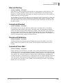
Data Network Assessment for Voice Traffic .............................................................................. 151
IP Interface Unit .......................................................................................................................... 151
Network Address Translation (NAT) .......................................................................................... 154
IP User Mobility .......................................................................................................................... 156
IPT Anywhere .............................................................................................................................. 157
Quality of Service (QoS) and Bandwidth .................................................................................... 158
Power Over Ethernet ................................................................................................................... 159
Toshiba SoftIPT IP Telephone .................................................................................................... 160
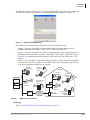
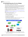
Private Networking Over IP to the Strata CIX ................................................................................... 162
Private Networking Over IP to the IPedge System ............................................................................ 163
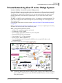
Private Networking Over IP to the VIPedge ...................................................................................... 164
SIP Trunking ...................................................................................................................................... 165
Integrated Services Digital Network (ISDN) ..................................................................................... 166
Least Cost Routing (LCR) ................................................................................................................. 166
Line Buttons ....................................................................................................................................... 167
CO Line Buttons .......................................................................................................................... 167
Pooled CO Line Button ............................................................................................................... 167
Group CO Line Button ................................................................................................................ 167
Live System Programming ................................................................................................................. 167
Lost Call Treatment ............................................................................................................................ 167
Message Waiting ................................................................................................................................ 168
LED Indication ............................................................................................................................ 168
Stutter Dial Tone ......................................................................................................................... 168
Microphone (External Unit) ............................................................................................................... 168
Music-on-hold .................................................................................................................................... 168
Multiple Call/Delayed Ringing .......................................................................................................... 168
Off-Hook Call Announce (OCA) ....................................................................................................... 169
Off-Premise Stations .......................................................................................................................... 169
Override .............................................................................................................................................. 170
Call Forward Override ................................................................................................................. 170
Class Of Service Override ........................................................................................................... 170
Do Not Disturb (DND) Override ................................................................................................. 170
Executive Override ...................................................................................................................... 170
Privacy Override .......................................................................................................................... 170
Paging ................................................................................................................................................. 171
Telephone Group Paging ............................................................................................................. 171
External Speaker Page Zones ...................................................................................................... 171
Emergency Page .......................................................................................................................... 171
Strata CIX General Description
08/14
7
Contents
Chapter 11 – Features
Night Ringing Over Selected Page Zones ................................................................................... 171
Power Failure Protection .................................................................................................................... 172
Power Failure Transfer ................................................................................................................ 172
Reserve Power Battery Backup ................................................................................................... 172
Privacy ................................................................................................................................................ 172
Remote Update ................................................................................................................................... 172
Repeat Last Number Dialed ............................................................................................................... 173
Ringing ............................................................................................................................................... 173
Ring Over Busy ........................................................................................................................... 173
Ringing Cadence .......................................................................................................................... 173
Delayed Ringing .......................................................................................................................... 173
Distinctive Ringing ...................................................................................................................... 173
Speed Dial .......................................................................................................................................... 174
One Touch Buttons ...................................................................................................................... 174
Station Hunting .................................................................................................................................. 174
Serial Hunting .............................................................................................................................. 175
Circular Hunting .......................................................................................................................... 175
Distributed Hunting ..................................................................................................................... 175
Camp on to Hunt Groups ............................................................................................................. 175
Station Message Detail Recording (SMDR) ...................................................................................... 175
Call Manager ...................................................................................................................................... 176
Microsoft® Lync® Integration .......................................................................................................... 177
Strata Net Multi-system Networking ................................................................................................. 178
Coordinated Numbering Plan ...................................................................................................... 178
Strata Net Basic Call Control ...................................................................................................... 178
Alternate Routing ........................................................................................................................ 179
Centralized Attendant .................................................................................................................. 179
Telephone DSS Buttons ............................................................................................................... 179
Centralized Voice Mail ................................................................................................................ 179
Network SMDR ........................................................................................................................... 180
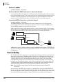
Survivability ....................................................................................................................................... 180
System Fault Finding and Diagnostics ............................................................................................... 181
Alarm Indication of System Faults .............................................................................................. 181
Secure Digital Card ..................................................................................................................... 181
Fault Detection and Error Logs ................................................................................................... 181
Event and System Administration Logs ...................................................................................... 181
Automatic Fault Recovery ........................................................................................................... 181
System Trace ............................................................................................................................... 181
Manual Test ................................................................................................................................. 182
Backup and Restore ..................................................................................................................... 182
Maintenance and Administration ................................................................................................. 182
Software Upgrade ........................................................................................................................ 182
Transfer .............................................................................................................................................. 182
Transfer with Camp On ............................................................................................................... 182
Transfer Immediate ...................................................................................................................... 182
Transfer Privacy .......................................................................................................................... 182
Transfer (Screened) ..................................................................................................................... 183
Transfer (Unscreened) ................................................................................................................. 183
Transfer to Voice Mail ................................................................................................................ 183
Music or Ringing Option ............................................................................................................. 183
8
Strata CIX General Description
08/14
Contents
Appendix – Specifications
Tenant Services .................................................................................................................................. 183
Traffic Measurement .......................................................................................................................... 183
Traffic Reports ............................................................................................................................. 184
Unified Communications ................................................................................................................... 184
Uniform Call Distribution .................................................................................................................. 184
Interaction with Other Features ................................................................................................... 185
User Programming Mode ................................................................................................................... 186
VLAN Tagging .................................................................................................................................. 187
Voice or Tone Signaling .................................................................................................................... 187
Voice Mail Integration ....................................................................................................................... 188
DTMF Integration ........................................................................................................................ 188
Simplified Message Desk Interface (SMDI) ............................................................................... 188
Toshiba Proprietary Integration ................................................................................................... 188
Direct Transfer to Voice Mailbox ............................................................................................... 189
Volume Control .................................................................................................................................. 189
Appendix – Specifications
Environmental Characteristics ........................................................................................................... 191
Power Considerations ......................................................................................................................... 192
CIX40 .......................................................................................................................................... 192
CIX100 ........................................................................................................................................ 192
CIX200 ........................................................................................................................................ 192
CIX670 and CIX1200 .................................................................................................................. 193
MAS Power Considerations ........................................................................................................ 193
Reserve Power .................................................................................................................................... 194
Strata CIX Component Compatibility ................................................................................................ 196
Public Network Requirements ........................................................................................................... 200
Station Loop Lengths ......................................................................................................................... 202
Standard Telephone Ringer Specifications ........................................................................................ 203
Standard Telephone Interface Options ............................................................................................... 204
5000/3000/3200-series Telephone Option Circuit Cards ................................................................... 204
Station Dimensions ............................................................................................................................ 205
IP Telephone Power Consumption ..................................................................................................... 206
System Tones ..................................................................................................................................... 207
Strata Net IP and IPT Bandwidth Requirements ................................................................................ 210
Strata CIX Software License Requirements ...................................................................................... 212
Capacities ........................................................................................................................................... 215
Device Monitor Capacities for Strata CIX Systems .................................................................... 225
Index ........................................................................................................................................................ 227
Strata CIX General Description
08/14
9
This page is intentionally left blank.
Introduction
This General Description provides an overview of the Strata CIX40, CIX100-S, CIX100, CIX200,
CIX670, and CIX1200 IP and digital business telephone systems, associated hardware and
features. The features described in this document assume that the Strata CIX/CTX system has the
current software release installed.
Organization
This document is divided into the following major topics:
•
Chapter 1 – Strata CIX Overview is a brief introduction of the Strata CIX systems.
•
Chapter 2 – Strata CIX40 describes the system, its basic capacities and system expansion.
•
Chapter 3 – Strata CIX100-S / CIX100 describes the system, its basic capacities and system
expansion.
•
Chapter 4 – Strata CIX200 describes the CIX200 system (hardware, software and circuit
cards), its unique attributes and basic functionality.
•
Chapter 5 – Strata CIX670 and CIX1200 describes the system, its basic capacities, system
expansion, and remote maintenance.
•
Chapter 6 – Universal Slot Circuit Cards provide information about Printed Circuit Boards
(PCBs) that can be installed in the universal slots of the Strata CIX/CTX systems.
•
Chapter 7 – Telephones and Peripherals describes the most recent Toshiba-proprietary
stations and peripherals, customer-supplied peripherals, as well as cabling and connectors.
•
Chapter 8 – Strata Media Application Server and Integrated Voice Mail Cards describes
the MAS, its basic capacities, system expansion, and remote maintenance. It also includes
some information about Voice Processing systems.
•
Chapter 9 – IPedge Application Server for Strata CIX describes the features of the IPedge
system that can be used with the Strata CIX system.
•
Chapter 10 – VIPedge Application Service for Strata CIX describes the VIPedge cloud
based services available.
•
Chapter 11 – Features describes the features which are available system-wide, as well as
stations features.
• Appendix – Specifications includes detailed information on environmental characteristics,
power considerations, hardware compatibility, network requirements, and station specifications
and system capacities.
Strata CIX General Description 08/14
ix
Introduction
Conventions
Conventions
Conventions
Description
Note
Elaborates specific items or references other information. Within
some tables, general notes apply to the entire table and numbered
notes apply to specific items.
Important!
Calls attention to important instructions or information.
Courier
Shows a computer keyboard entry or screen display.
“Type”
Indicates entry of a string of text.
“Press”
Indicates entry of a single key. For example: Type prog then
press Enter.
Plus (+)
Shows a multiple PC keyboard or phone button entry. Entries
without spaces between them show a simultaneous entry.
Example: Esc+Enter. Entries with spaces between them show a
sequential entry. Example: # 5.
Tilde (~)
Means “through.” Example: 350 ~ 640 Hz frequency range.
Denotes a procedure.
Denotes the step in a one-step procedure.
Start > Settings > Printers
See Figure 10
x
Denotes a progression of buttons and/or menu options on the
screen you should select.
Grey/Blue words within the printed text denote cross-references.
In the electronic version of this document (Library CD-ROM or
FYI Internet download), cross-references appear in blue hypertext.
Strata CIX General Description 08/14
Introduction
Related Documents/Media
Related Documents/Media
Installation and Programming Manuals
• Strata CIX Installation & Maintenance Manual
• Strata CIX Programming Manual (Volume 1)
• Strata CIX Programming Manual (Volume 2 – Stratagy ES Voice Mail Application)
• Strata CIX Programming Manual (Volume 3 – Application Implementation)
User Guides
• Strata CIX IP5000-Series Telephone
• Strata CIX DP5000-series Telephone
• Strata CIX IPT Telephone
• Strata CIX DP Telephone
• My Phone Manager™
• Strata CTX DKT3001/2001 Digital Single Line Telephone
• Strata CIX Standard Telephone
• Strata CIX DKT2404-DECT Cordless Telephone
• Strata DKT2204-CT/DKT2304-CT Cordless Telephones
Quick Reference Guide
• Strata CIX IP5000-Series Telephone
• Strata CIX DP5000-Series Telephone
• Strata CIX/CTX DKT/IPT Telephone
CD-ROMs
• Strata CIX Application Software and Documentation Library – includes eManager™ software.
• Strata CIX Call Center Solutions Application Software and Documentation Library
For authorized users, Internet site FYI (http://fyi.tsd.toshiba.com) contains all current Strata CIX
and CTX documentation and enables you to view, print and download current publications.
Strata CIX General Description 08/14
xi
This page is intentionally left blank.
Strata CIX Overview
1
The Strata CIX family includes the CIX40, CIX100-S, CIX100, CIX200, CIX670, and CIX1200
Internet Protocol (IP) systems that provide sophisticated business communication features. These
systems deliver on the promise of IP telephony by providing all the features and benefits of our
traditional business communications systems on a converged IP platform. With the Strata CIX,
you have a choice of mixing and matching technologies, creating a pure IP system or a converged
solution, and changing based on the needs of your company. The Strata CIX systems can be
networked to the IPedge system and VIPedge Cloud-based Business Telephone Solution. Refer to
Private Networking Over IP to the IPedge System and Private Networking Over IP to the VIPedge.
Important!
The Strata CIX100-S uses the same hardware and configuration as the Strata
CIX100, with a few exceptions. Whenever the CIX100 is mentioned in this book, it
applies to both the CIX100-S and CIX100, unless specified otherwise.
The Strata CIX IP business communications system provides pure IP peer-to-peer functionality,
offers FeatureFlexTM adaptability capabilities, and provides a smooth migration path from Toshiba
Strata CTX and Strata DK digital business communication systems.
The Strata CIX supports many types of telephones and provides the configuration flexibility to
build the communications system you need, in addition to the investment protection from re-using
devices from other Strata systems. That’s why the Strata CIX is much more than just an IP system.
It is a unified communications environment that supports many types of client devices.
Available with the Strata CIX is Toshiba’s SIP Trunking I-VoIP service (SIP Trunking). Toshiba’s
integrated SIP Trunking service and equipment enable businesses to choose a single-vendor
business telephone service and equipment solution.
Optionally available with the Strata CIX is the Strata Media Application Server (MAS), which
allows multiple applications to be combined on a single device. Applications include Auto
Attendant, Voice Mail, Automated Speech Recognition (ASR), Text-to-Speech, Unified
Messaging, Interactive Voice Response (IVR), Automatic Call Distribution (ACD) and Reporting,
Web browser-based Personal and System Administration, Web-based Telephone Applications,
FeatureFlex adaptability tools, and third-party applications. For more information on the MAS,
please refer to Chapter 8 – Strata Media Application Server and Integrated Voice Mail Cards.
Strata CIX General Description
08/14
1
This page is intentionally left blank.
Strata CIX40
2
This chapter provides a system overview of the
Strata CIX40 telephone system.
The CIX40 is an IP communication system that
brings powerful IP telephony and Strata Net
networking capabilities to small customers and
branch office locations.
The Strata CIX40 system is a compact system that
provides large system features (for dimensions, see
Table 1). The CIX40 is designed for wall mounting
and occupies very little space.
An optional 4~8 port, 40-hour integrated plug and
play Toshiba Voice Processing system (GVPH1A)
with built-in modem plugs into a dedicated slot in
the Strata CIX40 cabinet. This integrated
combination of the Strata CIX40 and GVPH1A is a
very powerful and cost-effective small business
solution.
The plug and play CIX40 is easy and very cost
effective to install. The default plug and play
configuration is already programmed in the CIX40
and GVPH1A voice processing system. Any
additional programming or changes to the CIX40
can be done by using the latest version of eManager software that is found on Internet FYI.
The CIX40 can be configured with up to 24 IP channels to support Toshiba IP Desktop and Soft
phones; SIP telephones, SIP trunks and IP Strata Net channels to network multiple Strata CIX
systems.
The CIX40 easily connects to outside public and private telephone lines. All of the telephones
(stations) tied to the system can have direct access to each other, as well as to the public and
private network. All lines, stations, and options are tied together through the cabinet.
The CIX40 does not require processor licenses for analog Caller ID CO Lines, the first four Voice
Mail ports, digital or analog station ports, DTMF Receivers, etc. The only licenses needed are for
Voice Mail ports 5~8, IP Strata Net networking channels, Toshiba IP telephones, SIP phones SIP
trunks and Soft IP telephones connected to the optional GIPU8, GIPH-X1A, MIPU16-1A and
MIPU24-1A IP interface cards.
Strata CIX General Description
08/14
3
Strata CIX40
Processor
Licenses are required on the Media Application Server (MAS), Stratagy, SES, and customer
provided PCs for applications such as ACD, Strata Call Manager (SCM), TASKE, FeatureFlex,
VCS, Insight, etc.
The CIX40 comes with built-in circuitry for eight digital telephone ports, four CO line ports with
Caller ID Interface, one standard telephone port, built-in maintenance modem, LAN/NIC
interface, and one power failure transfer relay.
The Strata CIX40 system capacity can be expanded by adding the following expansion
components shown in parenthesis:
The fully expanded CIX40 system with optional interface cards provides the following capacities:
• 11 loop start CO line ports with Caller ID and 16 digital station ports (GCDU2A and
GCOCIH1A).
• Two standard telephone ports (GSTU1A).
• Eight, 16 or 24 IP channels for IP for any combination of telephone or Strata Net connection
(GIPU8, GIPH-X1A, MIPU16-1A or MIPU24-1A).
• 4, 6 or 8 voice mail ports with 40 hours of message storage and 360 mailboxes (GVPH1A, LIC2 GVPH for 6 or 8 port).
• Four serial interface ports (BSIS).
The table below lists the CIX40 cabinet physical specifications
Table 1
CIX40 Cabinet Specifications
Cabinet
Weight
Height
Width
Depth
Cabinet (CHSU40A2)
The system cabinet is off-black and contains 6.6 lbs.
the GMAU/GMAS motherboards
18 in.
12.2 in.
3.5 in.
Processor
The Strata CIX40 processor (GCTU2A) is a standard part that plugs into a dedicated CIX40
cabinet slot.
The Strata CIX40 uses a high-speed 32-bit RISC processor, DRAM working memory, SRAM with
lithium battery to back-up memory.
The Strata CIX40 processor has the following standard components built-in:
• Secure Digital (SD) memory card interface for program data backup, software upgrades,
alarms, error logs, and admin logs done locally or remotely.
• Network Interface Card port provides one circuit for 100base-TX Ethernet LAN connection of
the eManager computer, ACD Server, CIX Attendant Console, Multimedia Application Server
(MAS) and CSTA applications.
• 33.6 Kbps/V.34 Factory installed AMDS1A maintenance modem for connecting the eManager
administration tool locally or remotely.
• One Music-on-hold (MOH)/Background Music (BGM) RCA jack to interface with external
MOH and/or BGM sources. The CIX40 can have up to three MOH/BGM source interfaces by
adding two additional MOH/BGM input sources, connected to the Standard Telephone
interfaces.
4
Strata CIX General Description
08/14
Strata CIX40
CIX40 Cabinet Slots
• One External Page RCA jack to interface with a Toshiba External Amplified Speaker (BESCB)
or a customer-supplied page amplifier and speaker(s) for external paging, night ring over
external page, and external BGM applications.
• One Relay control interface that provides an interface to a normally open relay contact which
can be programmed to control a Night Bell, door lock or to mute BGM during an external page.
• Memory Protection Battery that protects data and the customers programmed configuration
from memory loss. This information will be maintained in a powerless system for at least six
years.
• 16 DTMF receivers.
• 16 Busy Tone (BT) detector circuits for Auto Busy Redial (ABR).
• 64 conference circuits.
• Digital volume PAD technology enables audio volume to be adjusted in eight steps to
compensate for conference and/or CO line network losses.
The optional Serial Port Interface Subassembly (BSIS1A) can be installed on the processor to
provides RS-232 interface ports for SMDR interface to Call Accounting devices, SMDI for
external Voice Mail devices, and future applications. The BSIS1A is not needed for the GVPH1A
voice mail system because the GVPH1A uses built-in SMDI through the back plane.
CIX40 Cabinet Slots
The CIX40 Cabinet has three dedicated slots
used for the GCTU2A system processor card,
GVPH optional Voice Mail circuit card and a
slot that can add either four analog lines
(GCOCIH1A) or 8, 16 or 24 IP channels
(GIPU, GIPH, MIPU16 or MIPU24) optional
VoIP interface cards. All other CIX40 optional
interface cards plug onto the Processor or the
Motherboard. The CIX40 does not support
CIX1200/670/200/100 circuit cards.
Large Scale Integrated (LSI)
Circuits (no licenses required)
The processor has an LSI circuit that supports
the following:
• 16 DTMF receivers
• 16 Busy Tone (BT) detector circuits for
Auto Busy Redial (ABR)
• 64 built-in conference circuits
• Built-in, adjustable, digital volume PAD
technology enables audio volume to be
adjusted in eight steps to compensate for
conference and/or CO line network losses
Strata CIX General Description
08/14
Figure 1
CIX 40 Interior
5
Strata CIX40
CIX40 Cabinet Slots
GCTU2A Processor Interfaces
Memory Protection Battery
If commercial AC power is lost or if a system is moved or stored without power, the processor has
an on-board battery that protects data and the customer’s programmed configuration from memory
loss. This information will be maintained in a powerless system for at least six years.
Relay Control Interface
An on-board terminal strip provides an interface to a normally open relay contact which can be
programmed to control a Night Bell, door lock or to mute BGM during an external page.
External Page Interface
A 600 ohm RCA jack is built into the processor to interface with a Toshiba External Amplified
Speaker Control box (BESCB) or a customer-supplied page amplifier and speaker(s) for external
paging, night ring over external page, and external BGM applications.
Music-on-hold/Background Music Interface
One 600-ohm RCA jack is provided on the processor to interface with Music-on-hold and/or
Background Music (BGM) sources. With the CIX40, you can have up to three MOH/BGM source
interfaces. The CIX40 Standard Telephone interfaces can be used to provide up to two MOH/BGM
input sources in addition to the processor MOH/BGM interface.
Secure Digital Memory
The processor has an on-board Secure Digital (SD) memory card slot. A SD memory card can be
inserted into the slot to backup and restore customer program data. It also makes it easy to upload
operating system data for software upgrades and is used to store maintenance log files.
CIX40 Processor Optional Subassembly
Optional subassembly can be attached to the GCTU2A processor to provide additional features.
The subassembly is:
BSIS (Serial Port Interface) – Provides up to two RS-232 interface ports for SMDR interface to
Call Accounting devices, SMDI for external Voice Mail devices, and two future applications.
Notes
• The GVPH does not require a BSIS SMDI port.
• The factory installed AMDS maintenance modem and Network Interface Card (NIC) come
built into the GCTU2A processor.
6
Strata CIX General Description
08/14
Strata CIX40
GVPH – Integrated Voice Mail
GVPH – Integrated Voice Mail
With the release of Strata CIX40, Toshiba is also introducing a plug and play voice mail circuit
card (GVPH1A) specifically for the Strata CIX40 cabinet. It plugs into a dedicated cabinet slot and
requires no additional hardware to provide its full set of features.
The CIX40 is pre-programmed to match all related voice mail programming in the GVPH Voice
Mail system. This includes station numbers, mailboxes, voice mail hunt groups, voice mail station
IDs and many other items which are listed in the CIX40 installation documentation. The preprogrammed data is set when the processor is initialized even if the expansion cards or GVPH1A
Voice Mail system is not installed prior to system initialization.
It provides comprehensive Auto Attendant/Voice Mail capabilities, including the following:
• 4-Voice Ports (default) and 6 or 8 ports with LIC-2 GVPH license.
• 40 hours voice storage or up to 10,000 total messages.
• 360 mailboxes.
• Voice Mail Call Monitor – answering machine like operation to monitor and optionally pick-up
a call when someone is leaving a voice message.
• Voice Mail LCD Feature Prompting with Soft Key Operation (English and Spanish).
• Call Record – enables the user to record live calls.
• Installs in a dedicated CIX40 cabinet slot with SMDI integration built-in on backplane – no
serial port or other interface hardware is needed for interface or for its full set of features.
• Built-in remote maintenance modem.
• Administration requires the GVPH UADMIN2 Administration Software.
This is a new version of Stratagy UADMIN2 exclusively for the GVPH1A.
It also includes a new software version program update and prompt update capability for
remote maintenance.
• The Backup and Restore function stores Names, Greetings, Mail box numbers, and all other
database parameters. It does not back up/restore user messages.
• Pre-programmed with default mail boxes that match CIX40 default stations numbers, adding
simplicity to any installation.
To program additional features beyond the default settings, refer to Strata CIX40 Voice Processing
Programming Manual and UADMIN2 software.
Feature Compatibility
The Strata CIX40 uses the same Release 5.10 software as Strata CIX100, CIX200 and CIX670
systems, so functionality and features are the same between them, with some exceptions that are
listed below.
The Strata CIX40 does not support the following capabilities:
• T1 and PRI digital trunk interfaces.
• DID, Ground start and Tie line analog trunk interfaces (supports Loop start with Caller ID).
• Dialed Number Identification Service (DNIS).
• Zone Page Interface.
• Analog Station: Caller ID, message waiting lamp control and off-premise stations
Strata CIX General Description
08/14
7
Strata CIX40
System Configuration
System Configuration
Following are Strata CIX40 configuration guidelines:
• Pre-programmed to initialize and match CIX40 extension numbers with GVPH1A voice
mailboxes. So the system is ready for use when it is powered up the first time.
• Supports all CIX Release 5.2 and above features, except Speaker OCA and OCA on Digital
Telephones; T1 and PRI digital trunk interfaces; DID, Ground start and Tie line analog trunk
interfaces (supports Loop start with Caller ID), DNIS, and Zone Page Interface.
• Fully Licensed for 18 digital and analog telephones, 4 Voice Mail ports and 11 analog CO lines,
4 RS232 ports and 16-DTMF/ABR circuits. Licensing is only required for Strata Net
networking channels, IP telephones, SIP phones, SoftIPTs, 6 or 8 voice mail ports, and MAS
applications.
• Maximum Capacity is 16 Digital telephones, 11 Loop start lines with Caller ID Interface, 2
Standard telephone interfaces, 8 Voice Mail ports, 24 IP channels, and 4 RS-232 Serial
Interface ports.
• Digital Telephone Compatibility – Supports Toshiba DP5000-series telephones, Add-on
modules and DSS console. The DP5000-series telephones include a 10 button telephone set
(DP5022-SDM) that is designed as a cost-effective telephone for the CIX40.
• IP Telephone Compatibility – Supports all Toshiba 2000-series and 5000-series IP telephones,
Add-on-Modules and DSS consoles, SoftIPT soft phones on laptops and PDAs, and SIP
telephones.
• CO Line Compatibility – Loop start lines with or without Caller ID.
• Up to 24 IP SIP and Strata Net trunks are supported.
GVPH1A Voice Mail (optional plug in voice mail card):
• 4, 6 or 8 ports, 40 hours storage for saved messages, 360 mailboxes (4 default, 6 or 8 require
LIC-2 GVPH).
• Works similar to IVP8R2 with additional features of Voice Mail Call Monitor, Voice Mail LCD
Feature Prompting with Soft Key Operation, and Call Record.
• Plugs into CIX40 dedicated cabinet slot.
• SMDI integration built-in on back plane – no serial port or other interface hardware needed.
• Built-in remote maintenance modem.
• Administration requires the GVPH UADM2 Administration Software. This is a new version of
Stratagy Admin exclusively for the GVPH1A.
• Pre-programmed with default mail boxes that match CIX40 default stations numbers, adding
simplicity to any installation.
8
Strata CIX General Description
08/14
Strata CIX40
System Configuration
Table 2
CIX40 System Configuration
Basic Configuration - No Licenses Needed
Basic Capacity
4 CO line w/CLID, 8 Digital Telephones and 1
Standard Telephone.
CHSU40A2 Cabinet, includes Power supply
and Mother Board. The CIX40 cabinet and
GCTU2A processor are boxed separately. The
cabinet and processor are also warranted and
repaired separately.
Expanded Configuration – No Licenses
Needed
Includes: 33.6 Kbps/V.34 Maintenance Modem,
Page interface, MOH interface, Control relay, 16
DTMF/ABR circuit, 1 Power Failure Transfer
interface, NIC port for 100base-TX Ethernet LAN
connection of eManager computer, ACD Server,
CIX Attendant Console, and CSTA applications,
and a Secure Digital card interface.
Capacity/Feature Option
GCDU2A (3-CO line/8-DKT expansion card)
3 CO line w/CLID and 8 Digital telephones
GCOCIH1A (4 - CO expansion card)
4 CO lines with CLID
GVPH1A (voice mail plug-in card)
4-port Toshiba Plug-in Voice Mail system
expandable to 6 or 8 ports with LIC-2 GVPH.
GSTU1A (standard telephone plug-on card)
1 Standard Telephone (total 2 standard
telephones)
BSIS1A (4-port RS-232 interface plug-on card).
SMDR for Call Accounting or SMDI for external
voice mail system
HPFB-6 one to two HPFB6 Battery with built-in Reserve Power (Battery Backup)
Chargers
Expanded Configuration – Licenses
Required
Expanded Capacity/Feature Option
GIPU8-1A (8-channel GIPU IP plug-in card)
GIPH-X1A (8-channel IP plug-in card).
MIPU16-1A (16 channel IP plug-in card).
MIPU24-1A (24 channel IP plug-in card).
IP License requirements:
Maximum 8, 16 or 24 channels for any mix of IP
LIC-CIX-STRN-CH – one license required for telephones or Strata Net networking channels.
each IP Strata Net channel (Strata Net system
license is not available).
LIC-CIX-IP PORT – one license required for
each IP Telephone, SIP phone and SoftIPT.
LIC-SOFTIPT – one license required for each
SoftIPT.
Note See the “CIX40 Functional Block Diagram” on page 12 to see how the circuit cards and
interface connectors can be used for connecting stations and peripherals.
Strata CIX General Description
08/14
9
Strata CIX40
System Configuration
Table 3
CIX40 R2 Cabinet Configurations (CHSU40A2 Cabinet/R5.1 SW)
Analog
CO Lines
Digital
IP Channels
Telephones
Equipment
4
8
0
Cabinet (CHSU40A2)
7
16
0
Cabinet, GCDU2A
8
8
0
Cabinet, GCOCIH
11
16
0
Cabinet, GCDU2A, GCOCIH1A
4
8
8, 16, 24
Cabinet, GIPU, GIPH1A, MIPU161A, MIPU241A
7
16
8, 16, 24
Cabinet, GCDU2A, GIPU, GIPH1A, MIPU16,
MIPU24
Voice Mail: GVPH1A can be installed in all of the above configurations to provide 4 default VM
Ports and expand to 6 or 8 VM Ports with the LIC2-GVPH license
Analog FX/Modem Ports: One analog station port is standard on the Base cabinet;
a second can be added by installing GSTU1A.
Table 4
CIX40 R1 Cabinet Configurations (CHSU40A Cabinet/R5.1 SW)
Analog
CO Lines
Digital
IP Channels
Telephones
Equipment
3
8
0
Cabinet (CHSU40A)
6
16
0
Cabinet, GCDU2A
7
8
0
Cabinet, GCOCIH
10
16
0
Cabinet, GCDU2A, GCOCIH1A
3
8
8, 16
Cabinet, GIPU8, GIPH1A, MIPU16
6
16
8, 16
Cabinet, GCDU2A, GIPU8, GIPH1A, MIPU16
Voice Mail: GVPH1A can be installed in all of the above configurations to provide 4 default VM
Ports and expand to 6 or 8 VM Ports with the LIC2-GVPH license
Analog FX/Modem Ports: One analog station port is standard on the Base cabinet;
a second can be added by installing GSTU1A.
10
Strata CIX General Description
08/14
Strata CIX40
Telephone and Console Support
Reserve Power
One or two HPFB-6 optional units can be added to the CIX40 to provide reserve power. The
amount of reserve power time depends on the hardware (see Table 5). The table below is an
estimate of battery backup time based on the premise that the HPFB-6 unit(s) are fully changed at
the time of AC power failure. This estimated backup time is based on normal call traffic, the time
estimates will be reduced by as much as half with extreme heavy traffic volumes.
Table 5
CIX40 Reserve Power Duration Estimates
Hardware
1 HPFB-6
2 HPFB-6
3CO/8DKT/DP - No GVPH
1 hr. 40 min.
3 hr. 20 min.
3CO/8DKT/DP - with GVPH
1 hr. 30 min
3 hr.
6CO/16DKT/DP - No GVPH
1 hr. 5 min.
2 hr. 10 min.
6CO/16DKT/DP - with GVPH
1 hr.
2 hr.
11CO/8DKT/DP - No GVPH
1 hr. 20 min.
2 hr. 40 min.
11CO/8DKT/DP - with GVPH
1 hr. 10 min.
2 hr. 20 min.
11CO/16DKT/DP - No GVPH
1 hr.
2 hr.
11CO/16DKT/DP - with GVPH
55 min.
1 hr. 50 min.
Note The CIX40 should be plugged into AC power and the DC power switch should be turned on
when installing the HPFB-6. The HPFB-6 will not start to operate if AC power is not
available during the initial installation.
Telephone and Console Support
The Strata CIX40 supports all current Toshiba 5000-series Telephones, Add-on Module, DSS
Console, and CIX Attendant Console. see Chapter 7 – Telephones and Peripherals.
The Strata CIX40 supports 3000-series and 3200-series digital telephones, including the
DKT3007-SD(W) and DKT3207-SD 7-button models, Add-on Module, DSS Console, CIX
Attendant Console, and generic single-line telephones (2500-sets). For details on Telephones and
Consoles, see Chapter 7 – Telephones and Peripherals.
The Strata CIX40 supports Toshiba 2000-series and 5000-series IP telephones, SoftIPT soft
phones on laptops and PDAs, and SIP telephones.
The Strata CIX40 does not support analog electronic telephones (6500-series, 6000-series, etc.) or
older IPT1020-SD IP telephones.
The Strata CIX40 supports CIX IP and Digital Attendant consoles.
Strata CIX General Description
08/14
11
Strata CIX40
CIX40 Functional Block Diagram
CIX40 Functional Block Diagram
The Functional Block Diagram below shows the circuit cards and interface connectors used for
connecting the stations and peripherals to the CIX40 R2 cabinet (CHSU40A2).
SMDR
Call
Accounting
Stratagy ES
Voice Mail
Up to Four Programmable Serial
(RS-232) Port Modular Jacks
Available
GCTU2A
Processor PCB
BSIS
SMDI for
Toshiba Proprietary
Integration
(Optional)
Remote
Maintenance
Modem
Toshiba Proprietary
Soft Key LCD Link
WAN/
Internet
DTMF/ABR
Receivers
RJ45
LAN
Ethernet
Interface
100Base TX
SD Card
Maintenance
and
Customer
Database
(RCA Jack) 600 ohm Interface to
Music On Hold and/or
Background Music Source
(RCA Jack) 600 ohm Interface to
External Paging Amplifier
(Relay Contact) for Night Relay,
Door Lock, or Page Mute
Conference
SW with PAD
25-pair
Amphenol
Connector
Remote CIX
eManager PC
FAX or Modem
GVPH (optional)
Voice Mail/
Auto Attendant
ACD
(CSTA)
Attendant
Console
RS-232 Maintenance port
Standard
Telephone
MDF
Power Failure
Telephone
(Co Line 1)
Maintenance
Modem
1-Std. Tel. Circuit
Mode
KSU Mother Board
Msg
Spdial
Mic
Redial
Spkr
Cnf/Trn
Page
Scroll
Feature
Vol
UAdmin
Network
Demarcation
Point
GSTU1A
4-loop
start lines
with Caller ID
(Optional)
1-Std. Tel. Circuit
8-Digital Tel.
Circuit
• Central Office
• Centrex
• PBX
IP5000 /
IPT 2000
Mode
Msg
Page
Scroll
Feature
CIX
Node
Spdial
Strata Net
4-loop
start lines
with Caller ID
Vol
Mic
Redial
Spkr
Cnf/Trn
Hold
WAN/
Internet
IP5000 /
IPT 2000
Mode
Msg
Page
Scroll
Vol
Redial
Spkr
Cnf/Trn
MDFB
Circuit
GCDU2A (Optional)*
Door Phones and
Lock Controls
GCOCIH1A (Optional)*
Mode
Mode
Page
Scroll
Scroll
Feature
Feature
Msg
(Optional)
GIPH-X1A
GIPU8, MIPU16
MIPU24
8, 16 or 24 IP Channels
Page
Spdial
Vol
Msg
Spdial
Vol
Mic
Redial
Spkr
Cnf/Trn
Hold
Mic
Redial
Spkr
Cnf/Trn
Hold
Digital Telephone
with DSS Console
Digital
Telephone
Feature
Spdial
Mic
Cordless
DKT
DDCB
8-Digital Tel.
3-loop
start lines
with Caller ID
Hold
Digital
Telephone
(DP) and
Add-on
Module
PFCT
Router
IP End Point
Hold
KSU Mother Board
Power Circuit
LAN
IP5000 /
IPT 2000
Mode
Page
Scroll
Feature
VoIP Channels
Msg
Spdial
Vol
Mic
Redial
Spkr
Cnf/Trn
Hold
Reserve Power
HPFB-6
Battery/Charger
* If GCOCIH1A is installed, then GIPH-X1A,
MIPI16-1A or MIPU24-1A cannot be installed
and vice versa.
AC Adaptor
120V AC, 60Hz
0012-cix40c
Figure 2
12
CIX40 Functional Block Diagram
Strata CIX General Description
08/14
Strata CIX40
Additional Specifications
Additional Specifications
Table 6
CIX40 Specifications
Category
Items
Specification
Input voltage rating
100-240VAC
Input current rating
1.3A max.
Input frequency
50/60 Hz
AC adapter output
voltage
+15V/4.0A
Voltage of inside
Power switch
Power failure back up
DC Switch
2 HPFB6: 2 hours
See page 11
Located inside cabinet
The amount of time depends on
hardware configuration. One hour
in HPFB6 means 6 CO+16DP with
GVPH based on HPFB6 is fully
charged.
Customer supplied
Grounding wire.
Ground wire must connect the
earth ground through the FG
terminal on the GMAU for safety
purposes and to protect noise.
AC Plug
2-pin (American)
Ground wire must connect the
earth ground through the FG
terminal on the GMAU for safety
purposes and to protect noise.
Operating
Temperature
0 - 40 C
Operating humidity
20 - 80%
Grounding
Environment
At full installation
-27.3V/+5.0V
1 HPFB6: 1 hour
Power
Remarks
Storage temperature
-20 - 60 C
Maximum ports
40
16: DP phones
6: Analog trunk
8: IP channel
Safety
System
4: Voicemail
2: Analog devices
4: Serial ports
Regulation
Safety
UL60950-1
EMC
FCC part15 class-A
USA
Network Performance FCC part68
FCC/ACTA
Registration
Numbers
ACTA/FCC Part 68 Registration for Key System Code (KD): CJ6KD03BDTCHS402
ACTA/FCC Part 68 Registration for Multifunction Code (MF): CJ6MF03BDTCHS402
ACTA/FCC Part 68 Registration for Multifunction Code (PF): CJ6PF03BDTCHS402
Strata CIX General Description
08/14
13
Strata CIX40
Station Loop Limits
Station Loop Limits
The table below provides the maximum loop limits for connection of telephones, lines, peripheral
equipment, and power supplies. The following information applies to only the Strata CIX40
system.
Digital Telephone/DIU/DDM Console/ADM/Loop Limits
Mode
DP5000, DKT3000, DKT3200-series or
DKT2000-series models, DP with BVSU2 or
DVSU or BHEU or HHEU.
DKT with BPCI
DKT with BPCI and BHEU
DSS3060 or DSS2060
DDCB3A
BATI, RATI
DKT with 1 ADM
DKT with 2 ADMs
CIX40 Cabinet or
Battery Backup1
Maximum line
length (24 AWG)
1 Pair
feet meters
CIX40 Cabinet
1000
303
Battery Backup
695
204
CIX40 Cabinet
1000
303
Battery Backup
500
151
CIX40 Cabinet
1000
303
Battery Backup
500
151
CIX40 Cabinet
1000
303
Battery Backup
675
204
CIX40 Cabinet
165
50
Battery Backup
500
151
CIX40 Cabinet
1000
303
Battery Backup
1000
303
CIX40 Cabinet
675
204
Battery Backup
165
50
CIX40 Cabinet
500
151
Battery Backup
33
10
1. Battery backup applies to instances when the system is being powered by batteries exclusively.
2. CIX40 Digital Telephones do not support Speaker OCA.
14
Strata CIX General Description
08/14
3
Strata CIX100-S / CIX100
This chapter provides a system overview of the
Strata CIX100-S and CIX100 telephone systems.
Base
Expansion
The Strata CIX100-S/CIX100 systems are
compact systems, yet they provide large system
features (see Figure 3 and Table 7). They are
designed for wall mounting and occupy very little
space.
The CIX100 processor (ACTU3A) comes with 32
ports (licensed) and can grow to 112 ports by
adding 4-port licenses.
The CIX100-S processor (ACTU3A-S) comes
with 16 ports (licensed) and can grow to 32 ports
by adding two eight-port licenses. Then, it can
grow to 112 ports with four-port licenses.
5976
Figure 3
CIX100-S / CIX100
Base / Expansion Cabinets
Note The Strata CIX100-S and CIX100 system
capacities depend on the licenses stored on the system processor and the hardware described
in this chapter.
Important!
The Strata CIX100-S uses the same hardware and configuration as the Strata
CIX100 with a few exceptions. Whenever the CIX100 is mentioned in this book, it
applies to both the CIX100-S and CIX100 unless specified otherwise.
Each ACTU3 basic processor can be configured with a one or two cabinet system. A single (Base)
cabinet system supports a combination of up to 64 Central Office (CO) lines and stations, while a
two cabinet system (Base and Expansion) can support up to 112 CO lines and stations.
System line and station capacity is expanded by adding CO line and station circuit cards and port
licenses into its universal slot architecture.
The CIX100 easily connects to outside public and private telephone lines. All of the telephones
(stations) tied to the system can have direct access to each other, as well as to the public and
private network. All lines, stations, and options are tied together through the cabinets.
Table 7
CIX100-S/CIX100 Cabinet Specifications
Cabinet
Weight1
Height
Width
Depth
Base Cabinet (CHSUB112)
19.4 lbs.
14.6 in.
11.9 in.
10.2 in.
Base + Expansion Cabinet (CHSUE112)
34.6 lbs.
14.6 in.
19.9 in.
10.2 in.
1. Weight includes the processor card in the Base Cabinet and four universal circuit cards in each
cabinet.
Strata CIX General Description
08/14
15
Strata CIX100-S / CIX100
CIX100-S and CIX100 Processors
CIX100-S and CIX100 Processors
Each system operates with one processor card (ACTU3A-S for CIX100-S, ACTU3A for CIX100)
that installs in a dedicated slot of the Base Cabinet. The processors incorporate the following
hardware features.
CPU/Memory
Either processor card uses a high-speed, 32-bit, RISC processor, Dynamic Random Access
Memory (DRAM) working memory, Static Random Access Memory (SRAM) with lithium battery
for memory back-up, and flash program memory.
Large Scale Integrated (LSI) Circuits
The processors each have LSI circuits that support the following:
• 16 DTMF receiver hardware processor are built into the ACTU3. Five or more DTMF
receivers require appropriate licenses.
• 16 Busy Tone (BT) detector circuits for Auto Busy Redial (ABR) are built into the ACTU3.
• 64 built-in conference circuits.
• Built-in, adjustable, digital, volume PAD technology enables audio volume to be adjusted in
eight steps to compensate for conference and/or CO line network losses.
Memory Protection Battery
If commercial AC power is lost or if a system is moved or stored without power, the processor has
an on-board battery that protects data and the customer’s programmed configuration from memory
loss. This information will be maintained in a powerless system for at least six years.
Relay Control Interface
An on-board terminal strip provides an interface to a normally open relay contact which can be
programmed to control a Night Bell or door lock or to mute BGM during an external page.
External Page Interface
A 600 ohm RCA jack is built into each processor to interface with a Toshiba External Amplified
Speaker (BESCB) or a customer-supplied page amplifier and speaker(s) for external paging, night
ring over external page, and external BGM applications.
Music-on-hold/Background Music Interface
A 600-ohm RCA jack and volume controls are built into each processor to interface with Musicon-hold and/or Background Music (BGM) sources (one of the jacks is for future use). With the
CIX100, you can have up to 15 MOH/BGM source interfaces by adding:
• Up to two BIOU circuit cards, each provides three MOH/BGM input sources
• An RSTU circuit card that provides up to eight MOH/BGM input sources
Secure Digital Memory
Each processor has an on-board SD memory card slot. A SD flash memory card can be inserted
into the slot to backup and restore customer program data. It also makes it easy to upload operating
system data for software upgrades and is used for maintenance functions (see “System Fault
Finding and Diagnostics” on page 181 for more details).
16
Strata CIX General Description
08/14
Strata CIX100-S / CIX100
CIX100 Cabinet Slots
Built-in Ethernet Connection
The ACTU processor has an on-board Ethernet 100Base-T Ethernet interface for connection to
Open Architecture Computer Telephony Interface (CTI) applications. This provides extensive call
control and telephone support for CTI applications. The Ethernet Network Interface Card (NIC)
port also enables connection to the following:
• CIX Attendant Console
• ACD server
• Local and Remote eManager PC
• Soft Key Control of Voice Mail features
CIX100 Processor Optional Subassemblies
Optional subassemblies can be attached to the ACTU3A-S or ACTU3A processors to provide
additional features. The subassemblies are:
• AMDS (Modem) – Provides a 33.6Kbps/V.34 modem for point-to-point local or remote
connection to the eManager administration PC.
• BSIS (Serial Port Interface) – Provides up to two RS-232 interface ports for SMDR interface
to Call Accounting devices, SMDI or Toshiba Proprietary interface to Voice Mail devices, and
two future applications.
CIX100 Cabinet Slots
Base Cabinet
The Base Cabinet has one dedicated slot used for the system processor card and four universal
slots (S101~S104), that can accommodate station, line or option circuit cards. It also houses a
power supply that is packaged with the cabinet.
Expansion Cabinets
One expansion cabinet has four universal circuit card slots (S105~S108) that can accommodate
station, line or option circuit cards. It also houses a power supply that is packaged with the cabinet.
DC POWER
DC POWER
DC
DC
AC
AC
TOSHIBA
AMAUE1A
S101
S102
S103
S104
TOSHBIA
DIGITAL BUSINESS TELEPHONE SYSTEM
MODEL CHSUB112A V 1A. NO R 10062
Strata CTX100 INPUT: 120Vac 60Hz 1.8A
TOSHIBA CORPORATION
S105
S106
S107
S108
TOSHBIA
C
US
DIGITAL BUSINESS TELEPHONE SYSTEM
MODEL CHSUB112A V 1A. NO R 10039
Strata CTX100 INPUT: 120Vac 60Hz 1.8A
49L7
E88891
TIM
MADE IN MALAYSIA
ZCP
TOSHIBA CORPORATION
MADE IN MALAYSIA
ZCP
6576
Figure 4
Base and Expansion Cabinet Interior
Strata CIX General Description
08/14
17
This page is intentionally left blank.
Strata CIX200
4
The Strata CIX200 supports 192 ports and can be
configured as a one or two cabinet system,
consisting of a Base Cabinet and one optional
Expansion Cabinet. One processor model
supports all Strata CIX200 configurations from
smallest to largest.
These cabinets are designed specifically to fit
standard (customer-supplied) 19” racks. The 19”
rack and rack screws must be supplied by the
dealer. Interface cables connect directly to the
front panel or exit the cabinet through a port on
the right side of the cabinet.
The CIX200 uses a single-card common control
processor unit (LCTU2A), with a high-speed 32bit RISC processor, 64 MB DRAM working
memory, SRAM with lithium battery on-board
flash program memory, and removable Toshiba
Secure Digital flash memory.
Base Cabinet
The Base Cabinet (CHSUB192A) has four slots. The upper left slot, labeled B101 is reserved for
the common control unit. The other three slots (labeled S101, S102 and S103) are universal card
slots capable of hosting any of the station, line, and option interface PCBs compatible with the
Strata CIX systems. The Base Cabinet also has a dedicated LSLU slot located at the back of the
cabinet for two analog ports with two connectors on the front of the cabinet.
Expansion Cabinets
One Expansion Cabinet (CHSUE192A) can be added to increase the system station and CO line
capacity. The Expansion Cabinet has four universal slots for interface cards (labeled S201 ~ S204).
Compatible interface cards include the MIPU / LIPU / LIPS IP interface cards and the current
Strata CIX interface cards that support CO lines, digital telephones, analog stations, etc.
Refer to “Capacities” on page 215 for cabinet slot and station/line capacities.
Strata CIX General Description
08/14
19
Strata CIX200
Basic Specifications
Basic Specifications
The following table lists the parts and basic specifications of the CIX200 Rack Mount Cabinets.
Height: 2U or 3.5 inches (88.9 mm)
Dimensions of each
cabinet – Base
(CHSUB192A) and
Expansion (CHSUE192A)
Width: 17.3 inches (440mm – without bracket);
19 inches (483 mm – with bracket)
Depth: 16.1 inches (410mm)
Weight: 16 lbs (7.2 kilograms)
Power Supply Unit (PSU)
Initially Built-in
19" Rack Installation
Dimension
IEC297-1 (EIA RS 310-D)
Installation
465.1mm (front face screw pitch – width)
Rack-mount (preferred) or Table top.
Important!
Do not place the equipment on the floor or in a dusty place.
Power Backup
An Uninterruptible Power Supply (UPS) is required for power backup on a CIX200. The UPS is
similar to the ones used for computer systems and networking equipment.
20
Strata CIX General Description
08/14
Strata CIX200
Configuration
Configuration
The two primary considerations in system configuration are Card Slot Use and Power Factor.
Card Slot Use
The card slots can each support up to 32 ports. There are a few card position requirements based
on cable lengths. These are discussed in detail in the Strata CIX Installation Manual. These
requirements do not affect the system capacities.
In general, determine the number and type of stations needed, the number and type of trunks, and
any additional requirements. Other requirements include voice mail, power fail transfer, tie lines,
etc. The total number of ports required must not exceed 192.
Expansion
Cabinet
Processor
Card
Base Cabinet
7530
Figure 5
Two Cabinet CIX
Power Factor
Power Factors for the CIX200 circuit cards are shown below. For all others please refer to the
Installation and Maintenance Manual.
• LCTU1A: No effect on Power Factor calculations
• MIPU: PF = 0.2
• LIPU-X1A: PF = 2.6
• LIPS-X1A: PF = 1.9
• LSLU1A: PF = 1.5
There are no Power Factor considerations for the new IP Telephones (IPT2010/2020/2008), addon modules (IADM2020 and IDSS2060), and DSS consoles because the power is not supplied
from CIX200 cabinet.
The system (-24V) Power Factor is 67 per cabinet. There is no +5V power factor consideration for
the CIX200. For an example on how to use the System Power Factor and for worksheets, refer to
the Strata CIX Installation and Maintenance manual.
Strata CIX General Description
08/14
21
Strata CIX200
CIX200 PCBs
CIX200 PCBs
Two circuit cards are specific to the CIX200 systems; the LCTU processor card and the LSLU, a
two-circuit, single-line, telephone interface card. The MIPU24 IP interface card with 24 channel
works with the CIX200. The LIPU, an IP interface with 16 resources expands to 32 with the LIPS
expansion card and works on all CIX systems.
PCB Option Considerations
Strata CIX PCBs can be configured for a variety of hardware and software options. Hardware
options are defined as either internal (generally related to optional PCB subassemblies) or external
(related to connection of peripheral equipment such as background music, voice mail, etc.).
Some PCBs must have hardware options, such as jumpers or switches, set prior to installation of
the PCB in the cabinet.
Common Control Processor Unit (LCTU)
The system operates with the LCTU2A processor PCB that installs in a dedicated slot of the Base
Cabinet. The Strata CIX200 processor has the following standard components built in:
• Secure Digital (SD) memory card interface. A SD flash memory card can be inserted to backup
and restore customer program data. It also makes it easy to upload operating system data for
software upgrades and maintenance functions.
Note LCTU1A uses Smart Media (SM) flash memory.
• One Music-on-hold/Background Music Interface is provided by an RCA jack and a volume
control that are built into the processor to interface with a Music-on-hold and/or Background
Music source. Up to 15 MOH/BGM sources are supported by adding up to two BIOU option
cards, each provides three MOH/BGM input sources, and a BSTU card that provides up to
eight MOH/BGM input sources. MOH/BGM source volume adjustment is controlled by
software programming.
• Network Interface Card (NIC) Ethernet 100Base-T Ethernet port for IP management and
connection to Open Architecture Computer Telephony Interface (CSTA) applications. This
provides extensive call control and telephone support for CTI applications.
• 16 built-in DTMF receivers (five or more DTMF receivers require licenses).
• 16 built-in Busy Tone (BT) detectors for Auto Busy Redial (ABR).
• 64 built-in conference circuits.
• Built-in, adjustable, digital volume PAD technology enables audio volume to be adjusted in
eight steps to compensate for conference and/or CO line network losses.
• Page connector – External Page interface.
• Relay connector – Relay Control interface.
• Memory Protection Lithium Battery that protects data and the customer’s programmed
configuration from memory loss. This information will be maintained in a powerless system for
at least six years.
Optional subassemblies can be added to the LCTU processor PCB to enable system expansion and
provide additional features. The subassemblies are:
BSIS interface PCB attaches to the LCTU to provide up to four RS-232 interface ports for
SMDR Call Accounting, and SMDI or Toshiba Proprietary Voice Mail interface.
AMDS (Modem) – Provides a 33.6Kbps/V.34 modem for point-to-point local or remote
connection to the eManager administration PC.
22
Strata CIX General Description
08/14
Strata CIX200
Modular or Amphenol Connections
Analog Standard Station Interface Unit (LSLU1A)
The optional 2-circuit LSLU card provides for connection of two analog devices, such as faxes,
modems, standard telephones, etc., without message waiting. The LSLU installs into a dedicated
mount in rear of Strata CIX Base Cabinet behind the processor slot. The LSLU does not occupy
any of the universal slots of the cabinet, so it does not reduce the maximum capacity of the system.
The two analog station ports are accessible on the front of the base cabinet via modular connectors.
Modular or Amphenol Connections
The Strata CIX200 provides a choice of using either RJ45 modular connectors or amphenol
connectors for terminating CO line and station interfaces.
•
•
•
Modular connectors provide an IT friendly environment using RJ45 cables and patch panel
connections in data racks.
Amphenol connectors provide efficient connection to existing voice cables terminated on the
wall on 110 or 66 blocks.
Either way, the installation technician can exercise his preference or the customer’s preference
for the type of connection that will take less time to install or save the customer money.
Modular RJ45 connectors are provided by adding optional extenders and modular faceplates to
CIX interface cards used in the Strata CIX200. This enables the modular interface cables to be
connected at the front panel of the CIX200 cabinet.
Amphenol connectors are provided by using CIX interface cards in the Strata CIX200 without
extender cards. In this configuration, amphenol interface cables are routed through the side of the
cabinet and a flat face plate covers the slot housing the card. See the Strata CIX Installation and
Maintenance Manual for more details on Modular or Amphenol connections.
The Strata CIX200 supports two different types of optional extenders for the other CIX interface
cards, depending upon the type of connectors that exist on the card.
Extenders
The CIX system uses two types of extenders. One type is connected between the interface card and
the cabinet backplane. This type of extender brings the interface connectors to the front of the
cabinet. The correct front plate for the interface card is packaged with the extender. These
extenders are optional.
The second type of extender plugs into the interface card front connector and presents different
connectors to the front plate. Some of this type are optional, such as the extender that connects to
the 25-pair Amphenol connector on the station card and presents eight or 16 modular connectors to
the front panel. Refer to Table 8.
Power Failure Transfer Unit (LPFU1A)
The optional 8-circuit LPFU card when used with the RCOU and RSTU cards can automatically
connect the CO line circuits to the Single Line Telephones (SLT) when system power fails. The
LPFU card installs onto the CO line card as an extender, so it shares the same cabinet slot. The
RCOU card must be in the slot above.
Strata CIX General Description
08/14
23
Strata CIX200
Modular or Amphenol Connections
LCNU-A1A, LCNU-B1A, LCNU-C1A, LCNU-D1A, LEXU, and LCNU-E1A
Table 8
Extender
LEXU-A1A
LEXU-B1A
LCNU-A1A
CIX Extender Use
Used For
Required
LIPU/MIPU Optional
BPTU1A
RDTU3A
BSTCIU1A
Optional
BDKU/
BDKS
RCOU3A
LCNU-C1A
RGLU3A
RDDU2A
BCOCIU1A
LCNU-D1A
REMU1A
Optional
Plugs into the 50-pin Amphenol socket on the interface card.
Extends modular connectors to the CIX200 chassis face.
Optional
Plugs into the modular connectors on the interface card.
Extends modular connectors to the CIX200 chassis face.
(See
Comments
Optional
Required
LCNU-E1A
RCIU2A
LPFU1A
Power Fail
Transfer
(See
Comments)
Required
The LCNU-C1A connects the CO lines and Caller ID in one
connector. If not used the connections must made on the
MDF.
Plugs into the modular connectors on the interface card.
Extends modular connectors to the CIX200 chassis face.
The LCNU-E1A is a set of small cables. These are required
only if the LCNU-C1A is used. Connects RCIU2A to the
LCNU-C1A to connect the Caller ID and CO line together in
one modular socket.
Required for power fail transfer operation. The LPFU1A is
two extender cards and two cables. The CO and Station
cards must be in adjacent slots.
LCNU-B1A
LCNU-A1A
LCNU-D1A
24
Extender installed between card and chassis backplane.
Interface card connectors are bought to the cabinet face.
Optional
BWDKU1A
LCNU-B1A
Comments
LCNU-C1A
LCNU-E1A
Strata CIX General Description
08/14
5
Strata CIX670 and CIX1200
Strata CIX670
The Strata CIX670 system provides sophisticated
telecommunication features in a modular system
designed for growth. Its universal slot architecture
enables you to select the combination of Central Office
(CO) lines, stations, and peripheral options that best suit
your needs.
The CIX670 BCTU basic processor can be configured
for smaller systems as a one or two cabinet system with a
capacity of up to 192 CO lines and stations combined. It
can expand to support up to seven cabinets with a
capacity of up to 672 CO lines and stations combined
with the BCTU/BEXU expanded processor (see
Figure 6).
System line and station capacity is expanded by adding
processor expansion Circuit Cards, cabinets and line/
station circuit cards and station/line licenses.
The CIX670 easily connects to outside public and
private telephone lines. All of the telephones (stations)
tied to the system can have direct access to each other as
well as to the public and private network.
The Base Cabinet and optional Expansion Cabinets are
the building blocks of the system. Each system has a
Base Cabinet, and can have from one to six Expansion
Figure 6
CIX 670 Base/
Cabinets. All lines, stations, and options are tied together
Expansion Cabinets
through the cabinets. There are two types of cabinets,
floor/wall mountable and rack mountable. See page 32 for details on rack mountable cabinets.
5398
The overall weight and dimensions of the CIX670 cabinets are shown in Table 9.
Table 9
CIX670 Floor/Wall Mount Cabinet Specifications
Cabinet
Weight
Height
Width
Depth
Base Cabinet (CHSUB672)
31 lbs.
11.625 in.
26.5 in.
10.3 in.
Expansion Cabinet (CHSUE672)
29 lbs.
9.75 in.
26.5 in.
10.3 in.
Strata CIX General Description
08/14
25
Strata CIX670 and CIX1200
CIX670 Processor Circuit Cards
CIX670 Processor Circuit Cards
The system operates with the BCTU only or the BCTU and BEXU processor circuit cards that
install in dedicated slots of the Base Cabinet. The BCTU and BEXU processor incorporates the
following on-board hardware features:
CPU/Memory
The CIX670 uses a high-speed, 32-bit, Reduced Instruction Set Computing (RISC) processor,
Dynamic Random Access Memory (DRAM) working memory, Static Random Access Memory
(SRAM) with lithium battery for back-up memory and flash program memory.
Large-scale Integrated (LSI) circuits
The processor has LSI circuits that support the following:
• BCTU provides 16 built-in DTMF receivers; 32 available using the BCTU and BEXU. For five
or more DTMF receivers, appropriate licenses are required.
• BCTU provides 16 built-in Busy Tone (BT) detectors for Auto Busy Redial (ABR); 32
available using the BCTU and BEXU.
• BCTU provides 64 built-in conference circuits; up to 96 conference circuits are available using
the BCTU and BEXU.
• Built-in, adjustable, digital volume PAD technology enables audio volume to be adjusted in
eight steps to compensate for conference and/or CO line network losses.
Memory Protection Battery
If commercial AC power is lost or if a system is moved or stored without power, the processor has
an internal battery that protects data and the customer’s programmed configuration from memory
loss. This information will be maintained in a powerless system for at least six years.
Music-on-hold/Background Music Interface
An RCA jack and volume control are built into the processor to interface with a Music-on-hold
and/or Background Music source. With the CIX670, you can have up to 15 MOH/BGM sources by
adding:
• Up to two BIOU circuit cards, each provides three MOH/BGM input sources.
• A BSTU or any analog station card that provides up to eight MOH/BGM input sources.
• MOH/BGM source volume adjustment is controlled by software programming.
Secure Digital (SD) Memory
The BCTU processor has an on-board Secure Digital card slot. A SD flash memory card can be
inserted to backup and restore customer program data. It also makes it easy to upload operating
system data for software upgrades and is used for maintenance functions (see “System Fault
Finding and Diagnostics” on page 181 for more details).
26
Strata CIX General Description
08/14
Strata CIX670 and CIX1200
CIX670 Processor Circuit Cards
Network Interface
The BCTU processor has an on-board Ethernet 100Base-T Ethernet interface for connection to
Open Architecture Computer Telephony Interface (CTI) applications. This provides extensive call
control and telephone support for CTI applications. The Ethernet Network Interface Card (NIC)
port also enables connection to the following:
• CIX Attendant Console
• ACD server
• Local and Remote eManager PC
• Soft Key Control of Voice Mail features
• Media Application Server (MAS)
CIX670 Processor Optional Subassemblies
Optional subassemblies can be added to the BCTU processor card to enable system expansion and
provide additional features. The subassemblies are:
• AMDS (Modem) – Attaches to the BCTU to provide a 33.6Kbps/V.34 modem for point-topoint local or remote connection to the eManager administration PC.
• BSIS interface card which attaches to the BCTU to provide up to four RS-232 interface ports
for SMDR Call Accounting and SMDI or Toshiba Proprietary Voice Mail interface.
Strata CIX General Description
08/14
27
Strata CIX670 and CIX1200
Strata CIX1200
Strata CIX1200
The Strata CIX1200 system provides
sophisticated telecommunication features in a
modular system designed for growth. Its
universal slot architecture enables you to
select the combination of Central Office (CO)
lines, stations, and peripheral options that
best suit your needs.
The CIX1200 HCTU basic processor can be
configured for smaller systems as a one or
two cabinet system with a capacity of up to
192 CO lines and stations combined. It can
expand to support up to seven cabinets with a
capacity of up to 672 CO lines and stations
combined with the HCTU/HEXAU expanded
processor. This configuration provides the
same number of ports as the CIX670.
However, it provides expanded feature
capacity for items such as LCR tables,
Network routing tables, etc.
The Strata CIX1200 can expand to support
twelve cabinets (shown right) with a capacity
of up to 1,152 CO lines and stations
combined with the HCTU/HEXBU expanded
processors.
CIX1200_BE
CIX 1200 Base/Expansion Cabinets
System line and station capacity is expanded
by adding processor expansion circuit cards,
cabinets and line/station circuit cards and station/line licenses.
The CIX1200 easily connects to outside public and private telephone lines. All of the telephones
(stations) tied to the system can have direct access to each other as well as to the public and private
network.
The Base Cabinet and optional Expansion Cabinets are the building blocks of the system. Each
system has a Base Cabinet, and can have from one to 11 Expansion Cabinets. All lines, stations,
and options are tied together through the cabinets. There are two types of cabinets, floor/wall
mountable and rack mountable. See page 32 for details on rack mountable cabinets.
The overall weight and dimensions of the CIX1200 cabinets are shown in Table 10.
Table 10
28
CIX1200 Floor/Wall Mount Cabinet Specifications
Cabinet
Weight
Height
Width
Depth
Base Cabinet (CHSUB672)
31 lbs.
11.625 in.
26.5 in.
10.3 in.
Expansion Cabinet (CHSUE672)
29 lbs.
9.75 in.
26.5 in.
10.3 in.
Strata CIX General Description
08/14
Strata CIX670 and CIX1200
CIX1200 Processor Circuit Cards
CIX1200 Processor Circuit Cards
The system operates with the HCTU (2 cabinets) only or the HCTU and HEXAU (7 cabinets) or
HCTU and HEXBU (12 cabinets) processor circuit cards that install in dedicated slots of the Base
Cabinet. The processor cards incorporate the following on-board hardware features:
CPU/Memory
The CIX1200 uses a high-speed, 32-bit, Reduced Instruction Set Computing (RISC) processor,
Dynamic Random Access Memory (DRAM) working memory, Static Random Access Memory
(SRAM) with lithium battery for back-up memory and flash program memory.
Large-scale Integrated (LSI) circuits
The processor has LSI circuits that support the following:
• HCTU provides 16 built-in DTMF receivers; 32 available using the HCTU and HEXAU and
48 using the HCTU and HEXBU. For five or more DTMF receivers, appropriate licenses are
required.
• HCTU provides 16 built-in Busy Tone (BT) detectors for Auto Busy Redial (ABR); 32
available using the HCTU and BEXAU and 48 using HCTU and HEXBU.
• HCTU provides 64 built-in conference circuits; up to 96 conference circuits are available using
the HCTU and HEXAU and up to 128 conference circuits using HCTU and HEXBU.
• Built-in, adjustable, digital volume PAD technology enables audio volume to be adjusted in
eight steps to compensate for conference and/or CO line network losses.
Memory Protection Battery
If commercial AC power is lost or if a system is moved or stored without power, the processor has
an internal battery that protects data and the customer’s programmed configuration from memory
loss. This information will be maintained in a powerless system for at least six years.
Music-on-hold/Background Music Interface
An RCA jack and volume control are built into the processor to interface with a Music-on-hold
and/or Background Music source. With the CIX1200, you can have up to 15 MOH/BGM sources
by adding:
• Up to two BIOU circuit cards, each provides three MOH/BGM input sources.
• A BSTU or any analog station card that provides up to eight MOH/BGM input sources.
• MOH/BGM source volume adjustment is controlled by software programming.
Secure Digital (SD) Memory
The HCTU processor has an on-board Secure Digital card slot. A SD flash memory card can be
inserted to backup and restore customer program data. It also makes it easy to upload operating
system data for software upgrades and is used for maintenance functions (see “System Fault
Finding and Diagnostics” on page 181 for more details).
Strata CIX General Description
08/14
29
Strata CIX670 and CIX1200
CIX1200 Processor Circuit Cards
Network Interface
The HCTU processor has an on-board Ethernet 100Base-T Ethernet interface for connection to
Open Architecture Computer Telephony Interface (CTI) applications. This provides extensive call
control and telephone support for CTI applications. The Ethernet Network Interface Card (NIC)
port also enables connection to the following:
• CIX Attendant Console
• ACD server
• Local and Remote eManager PC
• Soft Key Control of Voice Mail features
• Media Application Server (MAS)
CIX1200 Processor Optional Subassemblies
Optional subassemblies can be added to the HCTU processor card to enable system expansion and
provide additional features. The subassemblies are:
• AMDS (Modem) – Attaches to the HCTU to provide a 33.6Kbps/V.34 modem for point-topoint local or remote connection to the eManager administration PC.
• BSIS interface card which attaches to the HCTU to provide up to four RS-232 interface ports
for SMDR Call Accounting and SMDI or Toshiba Proprietary Voice Mail interface.
30
Strata CIX General Description
08/14
Strata CIX670 and CIX1200
CIX670 and CIX1200 Cabinet Slots
CIX670 and CIX1200 Cabinet Slots
Base Cabinet
The Base Cabinet has two dedicated slots used for the system processor cards and eight universal
slots, labeled “S101~S108,” that can accommodate station, CO line or option circuit cards
(see Figure 7). It also houses a power supply.
B101
B102
S101
S102
S103
S104
S105
S106
S107
S108
DC OUT
-24V1
-24V2
BATT
+
-
-24V3
-24V4
POW
+5V
AC IN
-5V
P.F.
POWER
ON
RESET
EXP
BASE
OFF
FG
B101
B102
S101
S102
S103
S104
S105
S106
S107
S108
5002
6965
xEXU
Figure 7
xCTU
Base Cabinet Interior
Expansion Cabinets
One to twelve Expansion Cabinets can be added to increase the system station and CO line
capacity. Each expansion cabinet provides 10 slots (S_01~S_10). Figure 8 shows an Expansion
Cabinet.
Refer to the following section for cabinet slot and station/line capacities. Table 58 and 59 show the
number of stations and CO lines allowed when additional cabinets and circuit cards are used.
Note CIX1200 expansion cabinets 8 through 12 must be connected with fiber optic cables (see
page 34).
DC OUT
DC OUT
CABINET NO.
2
3
4
5
6
7
-27V1
-27V1
S_01
S_02
S_03
S_04
S_05
S_06
S_07
S_08
S_09
S_10
-27V2
-27V2
-27V3
-27V3
-27V4
-27V4
AC IN
BATT
++
--
POW
POW
+5V
+5V
AC IN
AC IN
-5V
-5V
P.F.
P.F.
RESET
RESET
POWER
POWER
ON
ON
EXP
EXP
BASE
BASE
FG
FG
S_01
Figure 8
S_02
S_03
S_04
S_05
Expansion Cabinet Interior
Strata CIX General Description
08/14
S_06
S_07
S_08
S_09
S_10
OFF
OFF
5002
5002
5003
31
Strata CIX670 and CIX1200
Strata CIX670 and CIX1200 Rack Mount
Strata CIX670 and CIX1200 Rack Mount
The Strata CIX670 and CIX1200 Rack Mount cabinets consist of
a Base cabinet (CRSUB672A) and Expansion cabinets
(CRSUE672A). These cabinets are deeper, narrower, and
designed specifically to fit standard (customer-supplied) 19”
racks (shown right). The cabinets are made of plated sheet metal,
dark gray in color with black cover plates. These cabinets support
the same features as the floor/wall-mountable CIX670 and
CIX1200 cabinets.
A CIX670 system can expand from one to seven cabinets using
the same processors and interface cards as the CIX670 floor/wallmountable cabinets. The CIX1200 system can expand from one
to twelve cabinets using the same processors and interface cards
as the CIX1200 floor/wall-mountable cabinets.The power factors
and slot configuration rules are also the same as the floor/wallmountable cabinets.
The difference between the floor/wall mount and the rack mount
cabinets is the size for the Base and Expansion cabinets, the
power supply that is installed in the cabinets, and a unique power
strip for rack mount cabinets (BRPSB120A and the 240V
version).
Toshiba does not support mixing the floor/wall-mountable
cabinets with the rack mountable cabinets. The 19 inch-wide rack
and rack screws must be supplied by the dealer. Interface cables
plug into the front of the station and trunk cards and fold under each cabinet to exit the rear of the
cabinets.
Basic Specifications
The following table lists the parts and basic specifications of the CIX1200 Rack Mount Cabinets.
Dimensions of Base (CSRUB672A)
and Expansion (CSRUE672A)
Cabinet
Height: 6U or 10.5 inches (267mm)
Width: 1.58 feet (483mm—with bracket)
Depth: 1.17 feet (358mm)
Weight of Base and Expansion
Cabinet
22.04 lbs. (10 kg)
Power Supply Unit (PSU)
BRPSU672A (initially built in) – can also be ordered for spares
19" Rack Installation Dimension
IEC297-1 (EIA RS 310-D)
465.1mm (front face screw pitch – width)
Installation
Optional Equipment
Cannot be floor or wall mounted.
Power Strip Box1
BRPSB120A
BRPSB240A
Reserve Power Battery Distribution Box
2
BBDB1A
From PSU to Battery Cable
PBTC1A-3M
From BBDB to Battery Cable
BBTC1A-2.0M
AC240V Power Supply Cord
BACL240A
1. Power strip boxes for floor/wall-mountable cabinets cannot be used for Rack Mount cabinets.
2. Reserve batteries are connected using the same battery distribution box and battery cables as the CIX670
and CIX1200 floor/wall-mountable cabinets.
32
Strata CIX General Description
08/14
Strata CIX670 and CIX1200
Strata CIX670 and CIX1200 Rack Mount
Base Cabinet
The CIX670 and CIX1200 rack mount base cabinet is similar to the Strata CIX670 and CIX1200
wall mount base cabinet. It has two dedicated slots used for the system processor cards and eight
universal slots, labeled “S101~S108,” that can accommodate station, CO line or option circuit
cards. It also houses a power supply. See Figure 9.
-24V1
-24V2
-24V3
-24V4
DC OUT
BATT
+
POWER ON
OFF
POW
+5V
-5V
P.F.
AC IN
RESET
EXP
BASE
B101
B102
xEXU
Figure 9
S101
S102
S103
S104
S105
S106
S107
S108
7163
xCTU
Strata CIX670 and CIX1200 Rackmount Base Cabinet Interior
Expansion cabinet
Each expansion cabinet provides 10 slots (S_01~S_10). Figure 10 shows an Expansion Cabinet.
-24V1
-24V2
-24V3
-24V4
DC OUT
BATT
+
-5V
POWER ON
+5V
OFF
POW
P.F.
AC IN
RESET
EXP
BASE
S_01
S_02
S_03
S_04
S_05
S_06
S_07
S_08
S_09
S_10
7164
Figure 10
Strata CIX670 and CIX1200 Rackmount Expansion Cabinet Interior
Strata CIX General Description
08/14
33
Strata CIX670 and CIX1200
CIX670 and CIX1200 Remote Expansion Cabinet
CIX670 and CIX1200 Remote Expansion Cabinet
A CIX670 and CIX1200 Expansion Cabinet can be located between a few inches and up to three
kilometers (1.86 miles) from its Base Cabinet. Remote Expansion Cabinets are enabled by the
fiber optic RRCU interface cards. One RRCU connects to up to two Data Cables and applies the
inter-cabinet signal to a multi-mode fiber-optic pair. One fiber pair can support one or two
Expansion Cabinets in one remote location using one RRCU in the Base Cabinet and another in
one of the Remote Expansion Cabinets.
CIX1200 expansion cabinets 8 through 12 must be connected as remote cabinets using RRCU
interface cards and multi-fiber optic cables.
Fiber connected cabinets support the BIOU for external Page Zones, Night Bell, etc., and all CO
line and trunk interface circuit cards. Network clock synchronization can only be derived from
digital trunks installed in the Base Cabinet or a expansion cabinet connected with standard ribbon
cables, not fiber cables.
A Remote Cabinet can support all circuit cards that can be installed in a local Expansion Cabinet,
including digital trunk cards. However, the system cannot derive network clock synchronization
from a digital trunk installed in a Remote Cabinet. This requires a digital trunk installed in the
Base Cabinet or in a local Expansion Cabinet connected to the Base by a standard ribbon cable.
For each Remote Cabinet location, local trunks may be required for correct 911 service.
34
Strata CIX General Description
08/14
Universal Slot Circuit Cards
6
Universal Printed Circuit Cards installed in the Strata CIX1200, CIX670, CIX200 or CIX100
cabinets provide interfaces for stations, lines, and peripherals. Each circuit card measures 7.5 x 5.5
inches (190 x 140 mm) and mounts in the slot with a 44-pin backplane connector. Circuit Card
external connections to station equipment are made to the Main Distribution Frame (MDF) using
industry-standard connectors.
Important!
This chapter does not apply to the Strata CIX40, except for GVPH, GIPU8, MIPU16
and MIPU24.
Station, Line and Option Circuit Cards
The Circuit Cards are categorized as station, CO line or option cards (see Tables 11~13). Feature
subassemblies that plug onto a universal slot circuit card are listed below the associated card. For
details, see the Strata CIX I&M Manual.
Table 11
Station circuit cards
Internet Protocol Telephone (IPT) Interface Unit (MIPU, LIPU/LIPS, GIPU and GIPH)
Provides IPT telephone circuits (IP5000-series,
MIPU16 – supports 16 IP channels (supported by CIX40 R1 and
IPT2010-SD, IPT2020-SD and IPT2008-SDL)
R2 cabinets)
1 100Base-TX RJ45 port
MIPU24 – supports 24 IP channels (supported by CIX40 R2
Built-in Digital Signal Processor (DSP)
cabinet)
1 RS-232 maintenance port
LIPU-X1A – supports 16 IP channels
Network Address Translation (NAT) compatible for LIPS-X1A – supports 16 IP channels and mounts on LIPU
remote IP telephones when connected to a MIPU /
LIPU/LIPS is not supported by CIX40
LIPU.
GIPU
8, GIPH-X1A – supports 8 IP channels for CIX40 only
Enhanced version of MEGACO+ for Voice over IP
Interface
Options: LAN, Virtual Private Network (VPN) Internet,
Supports SIP telephones and UIP200
VPN WAN, Intranet.
Simultaneously supports Line interfaces.
Digital Telephone Interface Unit (ADKU, BDKU/BDKS, BWDKU1A)
Provides digital telephone circuits for DP5000series, DKT3000/3200-series digital telephones.
ADKU = 8 circuits (CIX100 only)
Stand-alone digital cordless telephone
BDKU = 8 circuits
DDM5060 console
BDKS = 8 circuits
DDSS3260 console
DDCB – Door Phone
BWDKU = 8 circuits
Stand-alone digital cordless telephone
DDM console
BATI – Digital Attendant Console
Strata CIX General Description
08/14
35
Universal Slot Circuit Cards
Station, Line and Option Circuit Cards
Table 11
Station circuit cards (continued)
Standard Telephone Interface Unit (LSLU - CIX200 only) (ASTU - CIX100 only)
Interface Options:
Standard telephones (no message waiting lamp control - no OPS
(48V))
Provides two standard telephone circuits.
Other single-line devices
Maximum number of ringers per circuit is one.
Alternate MOH/BGM source
Fax machines
Voice mail devices
Standard Telephone Interface Unit (Card Slot Mount) (BSLU/BSLS - All CIX Systems)
Interface Options:
Standard telephones (no message waiting lamp control)
Other single-line devices
Provides eight (BSLU) or 16 (BSLU + BSLS)
standard telephone circuits. Maximum number of Alternate MOH/BGM source
ringers per circuit is one
Fax machines
Voice mail devices
No 48 Volt Off-premises Station support
Standard Telephone Interface Unit with Caller ID (Card Slot Mount) (BSTCIU - All CIX Systems, except CIX40)
Interface Options:
Standard telephones with Caller ID displays
Provides eight standard telephone circuits with
Caller ID. Maximum number of ringers per circuit is Message Waiting Lamp Control
three. The BSTCIU2A offers disconnect
Off Premise Station (OPS)
supervision.
VM devices
MOH / BGM
Standard Telephone Interface Unit (BSTU)
Interface Options:
Standard telephones
Voice mail ports
Provides 8 standard telephone circuits. Stutter dial Off-premises stations
Other similar devices
tone is provided for Message Waiting audible
indication. The BSTU2A offers disconnect
Alternate MOH/BGM source
supervision.
Auto Attendant digital announcer
Message Waiting Lamp Control
Fax machines
ACD announcer
-48 Volt Supply Internal Option (R48S)
Attaches to BSTU and BSTCIU
Interface Options: Optionally interfaces to the BSTU and
48VDC circuit for up to 8 standard telephone
BSTCIU to extend loop length of standard telephones from 600
circuits.
ohms to 1200 ohms. Required for OPS operation.
Not available on LSLU, BSLU/BSLS, ASTU
Voice Mail
Pre-programmed Voicemail Auto attendant circuit card.
4 Voice mail / Auto attendant ports default; 6 and 8 ports require
LIC-2 GVPH
GVPH (CIX40 only)
40 hours storage – 360 mail boxes
Call record, Voice mail Call monitor and built-in modem
Pre-programmed Voicemail Auto attendant circuit card.
LVMU1A (CIX100, CIX200, CIX670, and CIX1200) 8 Voice mail / Auto attendant ports
40 hours storage – 360 mail boxes
Call record, Voice mail Call monitor and built-in modem
36
Strata CIX General Description
08/14
Universal Slot Circuit Cards
Station, Line and Option Circuit Cards
Table 11
Station circuit cards (continued)
Stratagy iES32 (CIX100, CIX200, CIX670, and
CIX1200)
Stratagy iES16 (CIX100, CIX200, CIX670, and
CIX1200)
Table 12
Preprogrammed for plug-and-play in CIX Base or Exp., provides
4~32 voice ports. Also supports fax server and Unified
Messaging (UM). 10/100BaseT Ethernet connection and a serial
port used for Toshiba Proprietary Integration (TPI). (See Stratagy
General Description for details).
The Stratagy iES16 is an integrated voice mail system that can
be installed in a card slot inside a Strata CIX system.
The Stratagy iES16 supports a maximum of 16 voice ports, and
is available in model increments of 4 ports (4, 8, 12, 16 ports).
The Stratagy iES16 also ships with Unified Messaging and 5
client seats standard, and can be configured for all of the
advanced applications of the iES32, specifically up to 4 channels
of fax and 8 channels of Text to Speech.
CO Line Circuit Cards
Strata Net Over VoIP Interface Unit (MIPU, LIPU/LIPS, GIPU and GIPH)
MIPU16 – supports 16 IP channels
MIPU24 – supports 24 IP channels
Provides 32 IP Strata Net channels
LIPU-X1A – supports 16 IP channels
1 100Base-TX RJ45 port
LIPS-X1A – supports 16 IP channels and mounts on
1 RS-232 maintenance port
LIPU
Based on IP Strata Net standard protocol (ECMA-336)
LIPU/LIPS is not supported by CIX40
Voice coding G.711/G.729A
GIPU8, GIPH-X1A – supports 8 IP channels for CIX40
Built-in Digital Signal Processor (DSP)
only
Simultaneously supports IPT Station interfaces
Interface Options: LAN, Virtual Private Network (VPN)
Internet, VPN WAN, Intranet.
SIP Trunking (MIPU)
Provides 24 IP Strata Net channels
1 100Base-TX RJ45 port
GIPU8 – supports 8 IP channels
1 RS-232 maintenance port
MIPU16 – supports 16 IP channels
MIPU24 – supports 24 IP channels
Voice coding G.711/G.729A
Built-in Digital Signal Processor (DSP)
Simultaneously supports IPT Station interfaces
Internet Protocol (IP) Interface Unit (BVPU)
Provides 4 VoIP Circuits as E&M Tie lines
1 10Base-T port
1 RS-232 maintenance port
H.323 standard for Voice over Internet Protocol (VoIP)
Caller ID Interface Unit (RCIU2 / RCIS)
Interface Options: LAN, Internet, WAN.
Provides 4 Caller ID circuits.
With RCIS: 8 circuits.
Interface Options:
Provides Caller ID LCD display for analog loop or ground
start lines with Caller ID. Requires: RCOU, RCOS,
RGLU2, RGLU3 or PCOU. Not compatible with T1.
Caller ID Interface Subassembly (RCIS)
Attaches to the RCIU2.
Same as RCIU2.
Direct Inward Dialing Interface Unit (RDDU)
Interface Options:
DID analog lines.
Enhanced 911 CAMA Trunk Interface Unit (RMCU/RCMS)
E911 CAMA circuits. Provides up to 4 CAMA trunk circuits.
The RMCU/RCMS eliminates the need for connection of
adjunct terminal adapter equipment to E911 CAMA trunks. E911 analog CAMA trunks.
Requires 1 or 2 RCMS circuit cards for 2 or 4 CAMA lines
respectively.
Provides 4 DID circuits.
Strata CIX General Description
08/14
37
Universal Slot Circuit Cards
Station, Line and Option Circuit Cards
Table 12
CO Line Circuit Cards (continued)
CAMA Trunk Subassembly (RCMS)
RCMS attaches to RMCU. Provides 2 E911 CAMA circuits. Same as RMCU.
Up to 2 RCMSs per RMCU for 4 CAMA lines max. (1 RCMS
comes packaged with the RMCU.)
Ground/Loop Start Interface CO Line Interface Unit (RGLU3)
Interface Options:
Provides 4 ground or loop start line circuits. Each can be
individually set for ground or loop start operation.
Analog loop or ground start analog lines.
ISDN Primary Rate Interface Unit (RPTU and BPTU)
Interface Options:
ISDN PRI
POTS
Provides (1~8B + D), (1~16B + D), or (1~23B + D) channels FX
(lines), depends on system programming.
Tie (senderized)
RPTU2 is required for Strata Net Networking.
Tie (cut through)
OUTWATS (intra-LATA) and (inter-LATA)
InWATS
Strata Net
Loop Start CO Line Interface Unit (RCOU3A and RCOS3A)
Provides 4 CO analog loop start line circuits.
Interface Options:
With RCOS, provides 8 CO analog loop start line circuits. CO analog loop start lines
Loop Start CO Line Interface Subassembly (RCOS)
Same as RCOU.
Provides 4 additional Loop Start CO lines. 1 RCOS
RCOU/RCOS requires RCIU2/RCIS to support Caller ID.
subassembly per RCOU.
Loop Start CO Line Interface with Caller ID Unit (BCOCIU1A)
Interface Options:
Provides four CO analog loop start line circuits.
CO analog loop start lines (Does not support Type 2
With BCOCIS1A, provides eight CO analog loop start line
Hook-Flash to answer a waiting call, does not provide
circuits. Caller ID interface is built-in, RCIU is not needed.
dial pluse output)
Loop Start CO Line Interface Subassembly (BCOCIS1A)
Provides 4 additional Loop Start CO lines with built-in Caller Same as BCOCIU1A.
ID interface. Mounts on the BCOCIU1A.
T1/DS-1 Interface Unit (RDTU)
Interface Options:
T1
Provides T1 (DS1) Interface: 1~8, 1~16, or 1~24 channels Loop start lines
(lines), depends on system programming.
Ground start lines
Tie lines (wink or immediate)
DID/DOD lines (wink or immediate)
Remote Expansion Cabinet Unit (RRCU)
Supports 2 CIX670 and CIX1200 remote cabinets. 62.5 mμ, Remote Cabinet not supported by main system reserve
multi-mode fiber.
power.
Tie Line Unit (REMU2)
Interface Options:
E&M Tie lines
2- or 4-wire transmission
Provides 4 analog Tie line circuits.
Type I and type II signaling
Immediate start
Wink start
38
Strata CIX General Description
08/14
Universal Slot Circuit Cards
Station, Line and Option Circuit Cards
Table 13
Option Circuit Cards
Interface Options: Provides Paging output (600 ohm and
3-watt amp), 4 zone paging relays, three MOH interfaces
and 4 control relays (Night Transfer and BGM mute).
Interface Options: Provides four RS232 ports.
Option Interface Unit (BIOU)
Option Interface Unit (BSIS)
Strata CIX General Description
08/14
39
Universal Slot Circuit Cards
Functional Block Diagrams
Functional Block Diagrams
The Functional Block Diagrams show the circuit cards and interface connectors used for
connecting the stations and peripherals (see Figures 11~15).
Up to Four Programmable Serial (RS-232)
Port Modular Jacks Available
SMDR
Call Accounting
ACTU3A
BSIS
SMDI or Toshiba Proprietary
Integration
Stratagy ES
Voice Mail
Processor PCB
1
Conference
SW with PAD
(Optional)
MOH/BGM Jack
+Volume Control
Toshiba Proprietary Soft Key LCD Link
AMDS 1
Remote Maintenance
Modem
Remote CIX
eManager PC
Hub
or
LAN
ACD
(CSTA)
Ethernet
Interface
RCA Jack
Screw Connection
Local CIX
eManager
DTMF/ABR
Receivers
2
License
Smart Media
Maintenance
and
Customer
Database
Data and Speech Highway
RJ45
Internet
Amplified Page Output (3 Watts)
Page output
Relay Contact
Music Source: External Zone Page
Background Music
1
BIOU
Interface PCB
(one or two per system)
ASTU
Virtual slot 09
Relay Contacts
Door Lock Control Relay
MOH/BGM
RCA Jacks
Night Bell Control Relay
MOH/BGM
Volume Controls
External Zone Page Relays (4 Zones)
External Page Amplifier (600 ohm Output)
APSU112
BGM Mute Control Relay
Cabinet
Power Supply
1
ABCS
Battery Charger
12V
Battery
12V
Battery
(2 or 4 Batteries)
Night Control Relay
ABTC - 3m Cable
1
Main Distribution
Frame (MDF)
Music Source 1: Background Music
and/or Music-on-hold
Music Source 2: Background Music
and/or Music-on-hold
Music Source 3: Background Music
and/or Music-on-hold
Figure 11
40
Notes
1. Optional.
2. License Control.
On this page, all equipment, except Stratagy ES,
connected to the system processor PCBs and
BIOU PCB is customer-supplied.
0014-cix40
CIX100 System Processor and Optional Interface Circuit Cards
Strata CIX General Description
08/14
Universal Slot Circuit Cards
Functional Block Diagrams
Up to Four Programmable Serial (RS-232)
Port Modular Jacks Available
SMDR
Call Accounting
LCTU2A Processor PCB
BSIS
SMDI and Stratagy ES Integration
Stratagy ES
Voice Mail
Conference
SW with PAD
(Optional)
AMDS1 Remote
Maintenance Modem
Toshiba Proprietary Soft Key LCD Link
Remote CIX
eManager PC
Internet
Hub
or
LAN
ACD
(CSTA)
DTMF/ABR
Receivers( Built-In )
Memory
Time Switch
RJ45
2
Ethernet
Interface
License
Secure Digital
Maintenance
and
Customer
Database
RCA Jack
Screw Connection
IP Attendant Console
Local CIX
eManager
Amplified Page Output (3 Watts)
Page output
Data and Speech Highway
MOH/BGM Jack
+Volume Control
110 V
AC only
Cabinet
Power Supply
Relay Contact
Music Source: External Zone Page
Background Music
MOH/BGM
RCA Jacks
Door Lock Control Relay
BIOU
Interface PCB
3
Relay Contacts, Page Output
MOH/BGM
Volume Controls
Night Bell Control Relay
External Zone Page Relays (4 Zones)
External Page Amplifier (600 ohm Output)
BGM Mute Control Relay
Notes
1. Optional.
Night Control Relay
Main Distribution
Frame (MDF)
Music Source 1: Background Music
and/or Music-on-hold
Music Source 2: Background Music
and/or Music-on-hold
2. Optional. See description of License Control
earlier in this chapter.
3. Optional one or two per system.
On this page, all equipment, except Stratagy ES,
connected to the system processor PCBs and
BIOU PCB is customer-supplied.
Music Source 3: Background Music
and/or Music-on-hold
Figure 12
0017-cix40
CIX200 System Processor and Optional Interface Circuit Cards
Strata CIX General Description
08/14
41
Universal Slot Circuit Cards
Functional Block Diagrams
Up to Four Programmable Serial (RS-232)
Port Modular Jacks Available
SMDR
Call Accounting
xCTU
BSIS
SMDI and Stratagy ES Integration
Stratagy ES
Voice Mail
Processor PCB
Conference
SW with PAD
(Optional)
AMDS1 Remote
Maintenance Modem
Toshiba Proprietary Soft Key LCD Link
Remote CIX
Network eManager PC
Internet
Hub
or
LAN
ACD
(CSTA)
DTMF/ABR
Receivers( Built-In )
Memory
Time Switch
2
Ethernet
Interface
License
xEXU
Processor PCB
Memory
IP Attendant Console
Secure Digital
Maintenance
and
Customer
Database
RJ45
DTMF/ABR
Receivers
( Built-In )
Time Switch
Local CIX
Network eManager
MOH/BGM
RCA Jacks
Amplified Page Output (3 Watts)
BIOU
Interface PCB
Data and Speech Highway
MOH/BGM Jack
+Volume Control
3
Relay Contacts, Page Output
MOH/BGM
Volume Controls
Music Source: External Zone Page
Background Music
Door Lock Control Relay
BPSU672
Night Bell Control Relay
Cabinet
Power Supply
Battery Charger
External Zone Page Relays (4 Zones)
12V
Battery
12V
Battery
(2 or 4 Batteries)
External Page Amplifier (600 ohm Output)
Notes
BGM Mute Control Relay
1. Optional.
2. Optional. See description of License Control
earlier in this chapter.
Night Control Relay
Main Distribution
Frame (MDF)
Music Source 1: Background Music
and/or Music-on-hold
Music Source 2: Background Music
and/or Music-on-hold
3. Optional one or two per system.
On this page, all equipment, except Stratagy ES,
connected to the system processor PCBs and
BIOU PCB is customer-supplied.
Music Source 3: Background Music
and/or Music-on-hold
Figure 13
42
0013-cix40a
CIX670 and CIX1200 System Processor and Option Interface Circuit Cards
Strata CIX General Description
08/14
Universal Slot Circuit Cards
Functional Block Diagrams
SIP Trunk Provider
CTX670 and CIX1200
Expansion Cabinets
Optical Fiber Cable
3 km/(1.86 mi.)
CIX Network
RRCU
(CIX670 and CIX1200 only)
Remote Cabinet Interface Card
MIPU,CiX
LIPU/LIPS
Remote Location(s)
Mode
Msg
Spdial
Mic
Redial
Spkr
Cnf/Trn
Page
Scroll
With or without
VPN Router
or Server
IP Network
Feature
Vol
Hold
With or without
VPN Router
or Server
MIPU, LIPU/LIPS
IP Telephone
Remote Location(s)
RCIU2
4 Caller ID Circuits
(Two 4-Wire Modular Jacks)
(Two 4-Wire Modular Jacks)
RCIS 4 Caller ID Circuits
RCOU3
Network
Demarcation
Point
4 Loop Start Co Lines (Analog)
(Two 4-Wire Modular Jacks)
(Two 4-Wire Modular Jacks)
RCOS (Optional PCB on RCOU Only):
4 Loop Start CO Lines (Analog)
BCOCIU
4 Loop Lines with Caller ID
(Two 4-Wire Modular)
Central Office
Centrex
PBX
Common Carrier
Other Telephone System
E911 Public Safety Answer
Point (PSAP)
4
Priviate Networking Lines
(Two 4-Wire Modular)
(Two 4-Wire Modular Jacks)
BCOCIS
4 Loop Lines with Caller ID
RGLU3
4 Loop or Ground Start CO Lines (Analog)
MDF 1
(Two 4-Wire Modular Jacks)
RDDU2
4 DID CO Lines (Analog)
Secondary Protectors 2
(REMU, Four 8-Wire Modular Jacks)
REMU2
4 E&M Tie Lines (Analog)
Data and Speech Highway
•
•
•
•
•
•
•
•
Toshiba RDTU3-CBL-KIT
RDTU3
Channel
Service 2
Unit (CSU)
8-wire Modular Jacks
• 2T1 / DS1(24 Channels / Lines)
• Loop Start, Ground Start, Tie, DID
• Digital Voice Lines
PLL Synchronization Circuits
RMCU
Trunk Circuits for E911
CAMA Line (2-wire Modular Jacks)
RCMS
2 Trunk Circuits
RCMS
2 Trunk Circuits
CAMA Line (2-wire Modular Jacks)
Toshiba RPRI-CBL-KIT
Channel
Service 2
Unit (CSU)
BPTU1
8-wire Modular Jacks
ISDN PRI (23B+1D channels)
Digital Voice/Data
4
QSIG networks (RPTU2)
1. RCIU2/RCIS tip/ring cross
connected to RCOU, RCOS, or
RGLU tip/ring at MDF.
2. Customer-supplied equipment.
3. U, S, T, R, are ISDN reference
model termination points.
4. RPTU2 is required for QSIG
Networking.
0015-cix40
Figure 14
CIX100, CIX200, CIX670, and CIX1200 CO Line Side Functional Block Diagram
Strata CIX General Description
08/14
43
Universal Slot Circuit Cards
Functional Block Diagrams
BWDKU
8 or 16 Digital Telephone Circuits
Cordless DKT
Digital Telephone (DP)
and Add-on Module
Mode
Msg
Spdial
Mic
Redial
Spkr
Cnf/Trn
Page
Scroll
Feature
Vol
Hold
BDKU
8 Digital Telephone Circuits and
BDKU/BDKS
16 Digital Telephone Circuits
Digital Telephone3
Mode
Page
Scroll
Feature
TAPI PC
iES32
Msg
4~32 Voice Mail Circuits (Programmable)
Digital Single Line
Telephone (DP)
Connects audio path to Attd Console
Handset 3
BATI
1
Spdial
Vol
1 Pair Modular Cord
Mic
Redial
Spkr
Cnf/Trn
RS-232 Cable
Hold
DDCB
IVP8
2~8 Voice Mail Circuits (Programmable)
IP Telephone
with DSS Console
Mode
Page
Scroll
Mode
Page
Feature
Msg
Spdial
Mic
Redial
Spkr
Cnf/Trn
Vol
MIPU/LIPU/LIPS
Msg
Hold
Scroll
MDFB
Door Phones and
Lock Controls
Feature
Digital Telephone
with DSS Console
Spdial
Vol
LAN
Mic
Redial
Spkr
Cnf/Trn
Hold
Mode
Page
Scroll
Feature
IP Telephone
Msg
Spdial
Mic
Redial
Spkr
Cnf/Trn
Vol
BSTCIU
Data and Speech Highway
8 Standard
Telephone Circuits
with Caller ID
R48S
(Option PCB)
-48 Volt
Loop Supply
VM Ports
Hold
Stratagy ES
Voice Mail
Standard
Telephone
(with caller ID)
PC
RS-232 Cables
2 Standard Telephone Circuits
ASTU (CIX100)
LSLU (CIX200)
16 Standard
Telephone Circuits
8 Standard
Telephone Circuits
Modem
Auto Attendant
(Dealer supplied)
BSLU/BSLS All CIX
BSTU 2
1
R48S
(Option PCB)
-48 Volt
Loop Supply
1-pair Modular Cords Fax
1
Secondary
Protector
Transformer
Music
on-hold
source
(up to 8)
Standard
Telephone
Off-premises Station1 (BSTU only)
Modular Jacks
Main Distribution Frame (MDF)
0016-cix40d
1. Customer-supplied equipment.
2. RSTU2 or above is required for standard telephone message
waiting lamp.
3. PDKU and RDSU should only be used for 2000-series digital
telephones. They do not support all of the 3000-series and 5000-series
digital telephone features, including LCD. The PDKU also does not
support BPCI, BATI and the CTX Attendant Console.
Figure 15
44
Strata CIX100, CIX200, CIX670, and CIX1200 Station Side Functional Block Diagram
Strata CIX General Description
08/14
Telephones and Peripherals
7
This chapter covers Toshiba’s 5000-series Digital Telephones (DP), Internet Protocol Telephones
(IP) and peripherals that are compatible with Strata CIX telephone systems.
DP5000-series Digital Telephones
The DP5000-series telephones replace the DKT3200-series telephones in the Toshiba product line.
All three generations of telephones, DKT2000, DKT3200 and DP5000, can co-exist with full
functionality in one Strata CIX system with Release 5.1 software or above.
Although the DP5000-series telephones can be used on a CTX28 they will have limited
functionality.
The DP5000 telephones have three operational modes:
• When connected to Strata CIX systems with Release 5.1 or above, they will automatically run
in DP5000 Mode.
• When connected to Strata CIX systems with older than Release 5.1 (including Release 3) the
DP5000-series telephones will automatically act as DKT3200 telephones; DP5000-series
telephones can also be programmed to act as DKT2000 telephones.
• When connected to a PDKU card DP5000-series telephones automatically act as DKT2000
telephones.
• The DP5000 Backlight feature will function on all Strata CIX systems, regardless of the system
software version.
Strata CIX General Description
08/14
45
Telephones and Peripherals
DP5000-series Digital Telephones
DP5000-series Telephone Illustrations
A
B
C
Legend
D
E
F
A. Status LED (message and ringing)
G
B. LCD Display
H
C. Softkeys
J
I
K
20 Programmable Feature Buttons 4-Line LCD Telephone
D. Programmable Feature Buttons
E. Message Waiting LED Button
F.
Microphone LED Button
G. Speaker LED Button
H. Volume
A
I.
Hold Button
J.
Microphone
K. Tilt stand
L. Off-Hook Button (Single Line
Telephone)
E
H
L
I
G
D
Single Line Telephone 1 Programmable Button
46
Strata CIX General Description
08/14
Telephones and Peripherals
DP5000-series Digital Telephones
DP5008
DP5018-S
Digital Single Line Telephone
Digital Speakerphone with 10
programmable buttons
DP5022-SDM (CIX40 only)
DP5022-SD
DP5122-SD
DP5032-SD
DP5132-SD
Digital Speakerphone with 20
programmable buttons, 4-line LCD
display with backlight option (shown
with KM5020)
Digital Speakerphone with 10 programmable
buttons 4-line LCD display
DP5130-SDL and DP5130-FSDL
Digital half duplex and full duplex speakerphone
options with 20 programmable buttons, 9-line
LCD display with backlight.
Strata CIX General Description
08/14
47
Telephones and Peripherals
DP5000-series Digital Telephones
The DP5000 Look
• Sleek low profile — less than 1-inch thick.
• Black body with dark gray keys.
• Metallic silver curved tilt stand with eight adjustable positions.
Large Display Area for Call Information
• New LCD Technology — High Contrast LCD panel.
• All LCDs are 24 characters wide.
• Four lines of LCD to display call information (on the DP5022-SDM, DP5022-SD, DP5122-SD,
DP5032-SD, and DP5132-SD telephones).
• Nine lines of LCD on the DP5130-SDL and DP5130-FSDL telephones.
• Advisory Messages.
• Automatic Number Identification (ANI).
• Caller ID, Name and Number with call history.
• Contrast adjustment (13 levels).
• Date/Time of Day.
• Dialed Number Identification Service (DNIS Name and Number).
• Feature Prompting Soft Keys that are used as an alternative to access codes or feature buttons.
Station users can access features by responding to LCD prompts.
• Called Number displays on outgoing calls (1~120 seconds).
LCD Key-Strip
• Integrated in the DP5130-SDL and DP5130-FSDL telephones.
• Integrated in the LM5110 add-on module. This module is supported on all of the DP5000 series
telephones except the DP5008.
• Key labels are programmable via eManager, MyPhone Manager (both local and remote), or
user programming mode.
• User programmable line and trunk labels.
• Feature labels – user selectable.
• Ease of deployment and dynamic changes.
Backlight LCD
• Available on: DP5122-SD, DP5132-SD, DP5130-SDL, DP5130-FSDL, and LM5110.
• Place the telephones anywhere: regular office, reception area, high-end home studio, hotel
lounge, low-light environments, etc.
• LCD backlight can be set to always on, always off or synchronized which turns backlight on
anytime activity is sensed on the telephone and will automatically shut off after a period of time
to conserve energy.
48
Strata CIX General Description
08/14
Telephones and Peripherals
DP5000-series Digital Telephones
Mic Mute
Note Not supported on DP5008.
• All models have microphone and half duplex speaker capability.
• Enhanced Mute – the handset and microphone are muted simultaneously.
• The MIC key on the telephones toggles between Mic and Mute. When Mic key is lit, hands free
communication is supported, when the Mic key is pressed and light is off, Mute is enabled.
Handset/Headset
• Built-In Headset Interface.
• Built-in Carbon Handset Interface controlled by software.
• Speaker Off-hook Call Announce (OCA) for all models except on the DP5008. Speaker OCA
requires the DOCA interface.
Note The CIX40 supports Handset Off-hook Call Announce (OCA) but not Speaker OCA.
• On hook dialing.
Shift and Hist Keys
The bottom left and right keys on the large screen telephones are called the Shift and Hist keys.
The Shift key toggles the LCD screen between flexible keys 1~10 and flexible keys 11~20. The
Hist key accesses the Caller ID history. These buttons have no function when the telephone is
connected to a Strata CIX system running on software released prior to R5.2 MT021.
Speaker Off-hook Call Announce (DOCA-1A)
Digital telephones equipped with DOCA-1A can receive Speaker OCA which enables stations to
receive internal calls over their speaker while on another call using the handset. The DOCA-1A is
not required in a telephone to originate OCA calls or in a digital telephone that receives OCA calls
through the handset or headset.
Speaker OCA Interface (DOCA-1A) cannot be installed in DP5008 telephones.
Strata CIX General Description
08/14
49
Telephones and Peripherals
DP5000-series Digital Telephones
DP5000-Series Telephone Tilt Angles
The DP5000-series telephones, except the DP5008, have three tilt positions built into the base.
There is also a tilt stand extension that adds an additional 20 degrees of tilt. When the telephone is
sitting on a desk or table there are a total of six different angles of tilt available. When wall
mounted there are two angles available.
The DP5008 base is fixed at 15 degrees. All other DP5000-series telephones and add-on module
can tilt at 150, 27.50, 350, 400, 47.50, and 600.
Tilt Stand Extension
Figure 16
DP5000-Series Desk-top Tilt Angle With Tilt-Stand Extension
0° (no) Tilt
Figure 17
50
-10° Tilt
DP5000-Series Wall Mount Angles
Strata CIX General Description
08/14
Telephones and Peripherals
Telephone Button Expansion Options
Telephone Button Expansion Options
Add-on modules connect directly to the telephones and do not require an additional interface
circuit (port). Up to two Add-on-Modules can be attached to a telephone to supplement the
telephone's 10 or 20 buttons.
The CIX supports a limited number of Add-on-Modules per cabinet (see Table 59 on page 215 for
the capacities of different common control units).
Expansion options for the Toshiba DP5000-series telephones are described below:
LCD Add-on -Module (LM5110)
The LM5110 adds 10 programmable LCD feature buttons
to the 5000-series telephones, these buttons can be
assigned as CO line, Directory Number, DSS, One Touch,
Speed Dial or any other flexible feature.
The LM5110 supports backlight and LCD labels, it can be
connected to any 5000-series telephone (except DP5008).
LM5110 shown with DP5130 Telephone
Key Module (KM5020)
The KM5020 adds 20 programmable feature buttons
to the 5000-series telephones. These buttons can be
assigned as CO line, Directory Number, DSS, One
Touch, Speed Dial or any other flexible feature.
KM5020 shown with DP5132-SD Telephone
Digital DSS Add on Module (DDM5060)
The DDM5060 console (shown right) is for system
attendants.
The DDM5060 operates alongside a digital telephone
and has 60 programmable feature buttons. These buttons
can be assigned as CO Line, Directory Number, DSS,
One Touch, Speed Dial or any other flexible feature. The
DDM5060 is not compatible with the DP5008.
Up to eight consoles can operate with one digital
telephone depending on CIX system (See Table 59 on DDM5060 shown with DP5132 Telephone
page 215).
The DDM5060 console uses LEDs to indicate call and feature status; the DSS has dual red and
green LEDs to help further define status, such as station in DND status. The DDM5060 console
connects to a digital station port on the ADKU, BDKU, or BDKS card.
Strata CIX General Description
08/14
51
Telephones and Peripherals
Cordless Digital Telephones
Cordless Digital Telephones
Toshiba offers three cordless digital telephone models, the DKT2404-DECT, DKT2204-CT and
the DKT2304-CT (see photos in this section). These compact cordless digital telephones bring
mobility and productivity to office telephones. Greater call access cuts down on leaving messages
and playing “telephone tag.”
The DKT2404-DECT delivers the DECT functionality for the Strata series of cordless digital
telephones. DECT technology minimizes any interference between base stations in proximity or
any surrounding WLAN access points.
The DKT2404-DECT provides a 24-character display for better compatibility with the Toshiba
DP5000 Series desk phones versus 16 characters on other cordless phone models. It provides four
programmable keys with an additional four speed dial keys.
The digital cordless telephones operate from the same digital station port as the DP5000-series
digital telephone. They can be attached to a Toshiba DKT3000- or 2000-series corded digital
telephone or used as a stand-alone. If a cordless telephone is attached to a DP5000, the DP5000
must be put into 2000 mode.
Some of the features the cordless models include:
•
•
•
•
•
•
•
•
•
•
•
•
•
•
Liquid Crystal Display (LCD) that wraps using two lines, total of 32 characters
Ringer and handset volume control
Single button access to: Conference, Hold, Redial, Message and Transfer features
Four programmable function buttons
Charging stand
AutoStandby
AutoTalk
Vibrate ringer alert
Out-of-range protection
Low-battery protection system
Headset jack (2.5mm)
Stand-alone or DKT operation
High quality ultra-secure conversation with 32Kbps Adaptive Differential Pulse Code
Modulation (ADPCM) voice code combination.
Three ring tones
Notes
• They cannot receive Group Pages or All Call Pages.
• The handset and base unit of each cordless telephone is equipped with the same security code.
In order for a handset to operate, it must be installed with the matching base unit.
Below is the feature comparison table of the DKT2404-DECT, DKT2204-CT and DKT2304-CT.
Table 14
DKT2404-DECT, DKT2204-CT and DKT2304-CT Feature Comparison
Feature
52
DKT2404-DECT
DKT2304-CT
Transmission
1.9 GHz DECT 6.0
900 MHz Digital Narrow Band
Number of Channels
Talk Time
Stand By Time
Battery Type
5 Channels
16 Hours
168 Hours
NiMH Battery
30 Channels
7 Hours
120 Hours
NiMH Battery
DKT2204-CT
900 MHz Digital Spread
Spectrum
10 Channels
6 Hours
96 Hours
Ni-Cd Battery
Strata CIX General Description
08/14
Telephones and Peripherals
Cordless Digital Telephones
DKT2404-DECT
Combined with the DKT2404-UDR100 repeater solution, the
DECT technology provides three to seven times the range
compared to the DKT2204-CT and DKT2304-CT models. Up
to six repeaters can be linked per base station, with up to three
capable of being daisy-chained in one direction, to extend
operation range to greater than 1000 feet in open areas.
The DKT2404-DECT battery life is sixteen hours talk time and
seven days standby time.
The DKT2404-DECT Phone provides:
DKT2404-DECT shown
with charger and Base
• Two-line LCD with 24-character display, plus one line for
icons.
• Dedicated Talk, Redial, Hold, Msg, Cnf/Trn, Menu/MUTE,
DKT2404-UDR100
Speaker keys.
• Four programmable keys plus four speed dial keys.
• Handset measurements in inches: 2.25 wide x 1.0 deep x 6.5 tall. For base and charger
measurements, see Table 47 on page 205.
DKT2204-CT
The DKT2204-CT uses 900MHz Digital Spread Spectrum
Technology. It’s the reduces unwanted interference and
provides superior voice communication security.
The DKT2204-CT provides:
• The range is two to three times greater than
analog cordless telephones.
• Good clarity that is indistinguishable from corded
telephones in most environments.
• Maximum security for up to 10 cordless digital telephones
that is almost impossible to scan.
• A wall-mountable separate base and charging unit are
provided with the telephone.
6828
Handset measurements in inches: 2.2 wide x 1.66 deep x 8.66
tall. For base and charger measurements, see Table 47 on page 205.
Note The DKT2204-CT works with Strata CIX and Strata DK telephone systems.
DKT2304-CT
The DKT2304-CT uses 900 MHz Digital Narrow Band
technology that provides:
• A range of two to three times greater than conventional
analog cordless telephones.
• Good clarity.
• Maximum security for up to 30 cordless digital telephones.
This DKT2304-CT handset is much smaller than previous
models. Measurement in inches: 2.0 wide x 1.25 deep x 5.5
tall. For base and charger measurements, Table 47 on page
205.
6829
Strata CIX General Description
08/14
53
Telephones and Peripherals
IP4100 DECT Telephone
IP4100 DECT Telephone
The IP4100 DECT telephone (shown right)
supports 8~10 simultaneous call sessions per
base and allows for seamless roaming between
bases in a multi-base configuration. The High
Definition voice enabled speaker and
microphone allows for crystal clear speech.
The handsets support more than 20 hours talk
time and 200 hours standby time in normal
operations. The IP4100 DECT telephones are
administered via a powerful web-based
management tool that simplifies
administration and installation.
Handset Features
• 2.0 inch color TFT back-lit display
• Li-ion battery for long talk time and
standby time
• Wideband Voice (HDSP) Basic and
Extended operations
IP4100 DECT Telephone and Base
• Over-air feature upgrade support
• DECT 6.0 frequency support with
encryption
• Back-lit keypad for easy operation in low-lit environments
• Laser-etched keypad numbers for extended life use
• Three soft keys for ease of operation
• Four programmable feature keys for flexibility in operations
• 2.5 mm headset jack
• Polyphonic ringer support
• Vibration ring support
• Additional battery charging station in handset charger
• High-quality speaker phone
• Belt clip
IP4100-BASE Features
•
•
•
•
•
•
•
•
54
Attractive design
Power over Ethernet support
Omni-directional internal antenna for flexible installation options
Antenna diversity switching to avoid interference
Frequency support 1920-1930mhz with Wi-Fi avoidance technology
Colored LED status indication for ease of installation and operation
Easy installation via web GUI interface
Built-in trouble-shooting tools.
Strata CIX General Description
08/14
Telephones and Peripherals
IP 5000-Series IP Telephones
IP 5000-Series IP Telephones
The IP5000-series telephones replace the IPT2000-series telephones in the Toshiba product line.
IPT2000- and IP5000-series telephones can coexist with full functionality in one Strata CIX
system, Release 5.2 software, or above.
The IP5000-series telephones have three operational modes:
• When connected to Release 5.2 CIX systems with LIPU or MIPU interface cards, they will
automatically run in IP5000-series mode.
• When connected to CIX systems with older than Release 5.1 (including Release 3), the IP5000series telephones will automatically act as IPT2000-series telephones.
• If the interface is a BIPU-M, the IP5000-series telephones will run in IPT2000-series mode.
Strata CIX40, CIX100, CIX200, CIX670, and CIX1200 systems running R4 and later software can
upgraded to Release 5.2 software. Systems running R3 must be updated to R4 processors then
updated to R5.2.
Strata CTX28 systems do not support IP telephones.
Toshiba offers five IP Telephone models with backlight displays (except IP5022-SD), full-duplex
speakerphones, and Gigabit Ethernet:
• IP5122-SD & IP5622-SD – 10-button IP speakerphone with 4-line x 24-character backlit
LCD. The IP5622-SD does not support Gigabit Ethernet, ADM, DSS, BESCB and carbon
handset/headset.
• IP5022-SD & IP5522-SD – 10-button IP speakerphone with 4-line x 24-character LCD
(without backlight)
The IP5022-SD & IP5522-SD have all the same characteristics as our IP5122-SD except the
backlight for the display. These telephones still have full feature functionality with its 4-line
display and 10 programmable buttons. However, the IP5022-SD supports Gigabit Ethernet,
while the IP5522-SD does not support Gigabit Ethernet, ADM, DSS, BESCB and carbon
handset/headset.
• IP5122-SDC – Looks and functions similar to the IP5122-SD telephone when connected to the
Strata CIX. This telephones fully support all the Strata CIX features and services of a regular
IP5122-SD telephone. However, this telephone can have a unique feature button called the
Analog Central Office (ACO) button to connect directly to your local Central Office. This
ACO feature enables you to make Emergency 911 calls and/or calls on your direct CO line by
bypassing your Strata CIX system. Power over Ethernet (POE) or AC power is required for the
telephone’s analog local line connection to operate.
• IP5132-SD – 20-button IP speakerphone with 4-line x 24-character backlit LCD
• IP5131-SDL & IP5631-SDL– 20-button IP speakerphone with 9-line x 24-character backlit
LCD and HTML interface with navigation key. This telephone has 18 Soft Keys located on the
sides of the large LCD to respond to the Strata CIX feature prompts, ten of these are
programmable feature buttons. The Shift key (Purple key) toggles the LCD screen between
flexible keys 1~10 and flexible keys 11~20. The IP5631-SDL does not support Gigabit
Ethernet and carbon handset/headset.
Note ACD and FeatureFlex application keys are not supported on programmable feature buttons
11~20 of the large 9-line display telephone.
Strata CIX General Description
08/14
55
Telephones and Peripherals
IP 5000-Series IP Telephones
IP5022-SD & IP5522-SD
10 programmable buttons, 4-line LCD
IP5122-SD, IP5122-SDC & IP5622-SD
10 programmable buttons, 4-line backlit LCD
IP5132-SD
20 programmable buttons, 4-line backlit
LCD
IP5131-SDL & IP5631-SDL
20 programmable buttons, large backlit LCD
with HTML support and navigation key
56
Strata CIX General Description
08/14
Telephones and Peripherals
IP 5000-Series IP Telephones
Features
The IP5000-series telephones include a speakerphone and are 802.3af standard compliant for
Power-Over-Ethernet (PoE). The IP Telephony product family also includes matching Add-On
Module and a DSS Console.
The IP5000-series telephones support a very comprehensive and powerful feature set including:
• Backlit Displays (except IP5022-SD)
• Gigabit Ethernet Switch (except IP5522-SD, IP5622-SD and IP5631-SDL telephones)
• Analog Central Office (ACO) button (IP5122-SDC only)
• Busy Lamp Field (BLF) display of station status.
• Background Music through telephone speakers.
• Paging over telephone speakers.
• IPT Anywhere
• Automatic Configuration
• Terminal Authentication (security)
• Off-hook Call Announce (OCA) over telephone handset.
• Speaker OCA when using MIPU / LIPU / LIPS, GIPU or GIPH.
Note IP5000-series telephones enabled with Speaker OCA require two IP channels from the same
IP interface card but only one end point license. The IP channel used for Speaker OCA is
only used during the OCA call and may be shared by all IP5000-series telephones.
• Built-in headset interface for headsets and external speaker connection (BESCB)
• IP Add-on Modules (except IP5522-SD and 5622-SD)
In addition, the 5000-series IP telephones contain several important features, including:
• Full-duplex speakerphone capability when using an MIPU / LIPU interface card in a CIX
system.
• 802.3af power over Ethernet compliant
• Integrated Application Processor for Voice Mail, Unified Messaging ACD, and other
applications
• Soft Keys to respond to the Strata CIX feature prompts.
• Additional feature adjustments, such as setting button beeps, room noise sensitivity and
handset busy override tone.
• An adjustable tilt stand base is built-in, providing flexible angle adjustment of the entire
telephone.
IP Protocol
The Strata CIX uses RFC3015 Media Gateway Control (MEGACO) enabling Strata systems to
provide all the feature functionality of digital-series telephones to IP telephone users.
Connectivity
IP telephones connect to either the MIPU, LIPU, LIPS, GIPU or GIPH in the Strata CIX system
running software version 5.2 or above. However, the IPT2008-SDL can only be connected to the
MIPU, LIPU/LIPS GIPU or GIPH. These telephones must be connected to MIPU / LIPU / LIPS,
GIPU or GIPH to use peer-to-peer Real Time Protocol (RTP) connection.
Note The Strata CIX also supports the IPT1020-SD. This telephone can be connected to a
BIPU-M card only. It does not support peer-to-peer RTP connection.
Strata CIX General Description
08/14
57
Telephones and Peripherals
IP 5000-Series IP Telephones
• These telephones do not use the System power supply, so there is no power restriction to limit
the number of IP telephones that can connect to an individual Strata system. The IP Telephones
have built-in connectors. The back of the telephone has connector labels. The telephones can be
powered by a local power supply on the PoE (Power over Ethernet).
• The RJ45 LAN jack connects the telephone to the network via the LAN cable supplied with the
telephone. These telephones operate on the network at 10/100Mbps and 1000Mbps (IP5000series with the exception of the IP5522-SD, 5622-SD, 5631-SDL telephones) and can be
connected to a fast switch hub, router, LAN, WAN, etc.
• The RJ45 PC jack can connect the IPTs to the user’s PC. The IPTs can operate like a switch, as
opposed to a hub, so the telephone can be connected directly to the LAN or Cable/DSL modem,
and then a PC can be connected to the telephone PC jack to connect to the LAN through the
telephone.
• The built-in headset jack enables headsets to be connected to the telephone. No optional
headset interface is required. The same carbon or ECM headset support used on Toshiba digital
telephones can also be used on IP telephones.
Capabilities
The Toshiba IP Telephones also have the following capabilities:
• The IPTs contain two types of codecs (coder/decoder): G.711 and G.729A. The codec
determines the IP telephone voice quality and network bandwidth requirements. The G.711
requires the most bandwidth and provides the best voice quality. The G.729A requires less
bandwidth, but it does not provide the best voice quality. The desired codec is selectable for
each IP telephone in IP station administration using eManager or Network eManager.
• The external ringer interface connector is mounted inside the telephone base. This enables
connection of an BESCB external speaker device to provide a loud ringer for the IP telephone.
• All telephones in the system can be IP telephones up to the system’s maximum station capacity
(see Table 59 on page 215).
• Terminal Authentication is an option that allows a particular IP telephone to keep a reserved
directory number on a CIX system. This prevents IP telephones from logging in with another
telephone’s directory number if the other telephone has been disconnected to be taken to
another location. This feature uses the unique Media Access Control (MAC) address that is
permanently coded into each telephone network interface circuit. The unique MAC address of
the telephone is assigned to a particular directory number in system programming.
• IPT firmware can be updated locally or remotely using eManager. This enables service
personnel to update IP equipment with new features and enhancements as they become
available. Updates require a brief interruption of IP telephone operation (a few minutes).
• IP telephones have a discovery retry timer to prevent network congestion when many IP
telephones request services simultaneously. If network congestion is detected, the telephone
will pause and then retry for service.
• IP telephones have loop back and ping capabilities for maintenance and fault finding purposes.
• IP telephones support Dynamic Host Configuration Protocol (DHCP) or static IP addressing.
58
Strata CIX General Description
08/14
Telephones and Peripherals
IP 5000-Series IP Telephones
Liquid Crystal Display (LCD) Models
The IP5022-SD, IP5122-SD, IP5522-SD, IP5622-SD, IP5122-SDC and IP5132-SD models
display up to 24 characters times four lines of information and provide four Soft Keys.
The IP5131-SDL, IP5631-SDL has 4 soft keys and a 9-line LCD. From the idle screen you can
access telephone directories and speed dial lists of names or departments, internal or external to
the telephone system. You can search by name or letter within a list.
The IP5131-SDL screen consists of Phone, Config, and Web-application screens. The screens
change easily by pressing the tab soft key.
• Phone screen – This screen is a 150 x 168 pixel LCD screen.
• Config screen – This screen can be used for Telephone configuration settings. Using this
screen, you can set the IP address, subnet mask, etc.
• Web screen – provides users with the access to the web page. This capability can be used to
create the custom applications designed to match with IP5131-SDL phone screen so that the
user can enter or retrieve the data from the IP5131-SDL phone.
All LCD telephone models can provide:
• Advisory Messages
• Automatic Number Identification (ANI)
• Caller ID, Name and Number with call history
• Contrast adjustment (13 levels)
• Backlight adjustment, except IP5022-SD (On/Off/Synchronized)
• Date/Time of Day
• Dialed Number Identification Service (DNIS Name and Number)
• Feature Prompting Soft Keys that are used as an alternative to access codes or feature buttons.
Station users can access features by responding to LCD prompts.
• Called Number displays on outgoing calls (1~120 secs.)
Strata CIX General Description
08/14
59
Telephones and Peripherals
Telephone Button Expansion Options
Telephone Button Expansion Options
Upgrade options for the Toshiba IP telephones are described below.
LCD Add-on Module (LM5110)
The LM5110 adds 10 programmable LCD feature buttons to
the 5000-series telephones (except the IP5522-SD and IP5622SD telephones), these buttons can be assigned as CO line,
Directory Number, DSS, One Touch, Speed Dial or any other
flexible feature.
The LM5110 supports backlight and LCD labels, it can be
connected to any 5000-series telephone (except DP5008).
Key Module (KM5020)
The KM5020 adds 20 programmable feature buttons to the
5000-series telephones. These buttons can be assigned as CO
line, Directory Number, DSS, One Touch, Speed Dial or any
other flexible feature.
IP Direct Station Selection (IDM5060)
Console
The IDM5060 console (shown right) is for system
attendants.
The IDM5060 operates alongside a IP telephone and has
60 programmable feature buttons. These buttons can be
assigned as CO Line, Directory Number, DSS, One
Touch, Speed Dial or any other flexible feature.
Up to three consoles can operate with one IP telephone
depending on CIX system. However, the IP5522-SD and
IP5622-SD telephones do not support an IDM.
The IDM5060 console uses LEDs to indicate call and feature status; the DSS has dual red and
green LEDs to help further define status, such as station in DND status. The IDM5060 console
connects directly to an IP5000-series station.
60
Strata CIX General Description
08/14
Telephones and Peripherals
CIX Attendant Console
CIX Attendant Console
The Strata CIX Attendant Console runs on a PC with Microsoft® Windows® 7 Professional,
Windows 2000 Professional or Windows XP Professional operating system. The Strata CIX
Attendant Console PC is equipped with an Intel two gigahertz CPU in a small, compact desktop
chassis that is just the right size for a receptionist’s desk. If there isn’t any room on the desk for the
system to lay flat, it can also be stood on its side for an even smaller footprint. Add to that the
powerful Strata CIX Attendant Console software, and you have a winning solution for any Strata
CIX installation!
The Console connects to the Strata CIX processor via the LAN as a Computer Supported
Telephony Application (CSTA). The Strata CIX system requires the processor NIC interface.
Each CIX Attendant console requires the LIC-ATT license which is bundled with the Toshiba
supplied Attendant Console PCs and software. The LIC-ATT license must be ordered separately to
enable the Console to be installed on a Dealer / Customer supplied PC. The latest Attendant
Console software is available at no charge on Toshiba FYI.
The minimum PC requirements for the CIX Attendant Console are:
•
•
•
•
Operating Software – Microsoft Windows XP Pro or Windows 2000 Pro
Processor – 2.0GHz Intel Pentium 4, Celeron or higher
Memory – 512M RAM
CD-ROM Drive, CD-R/W Drive or DVD capable of reading CD-ROM data files to install
Attendant Console software.
• Hard Drive: 500M space available
• Sound card with internal or external speakers
There are two types of CIX Attendant Consoles; each operates and functions the same but each
provides a different type of talk-path.
The following Attendant Console hardware is available from Toshiba:
• CIX-DATTCONS – provides a digit talk path like a digital telephone and requires a BDKU
interface port. Includes software and LIC-ATT license.
• CIX-IPATTCONS – provides an IP talk path like IP telephones and requires an MIPU / LIPU
interface port. Includes software and LIC-ATT license.
Each of the above CIX Attendant Consoles consists of the following standard items:
• Attendant Console License (LIC-ATT) for the CIX processor (bundled with Toshiba Console
part number)
• LIC-ATT must be ordered separately if using a Dealer supplied PC for the Attendant Console
• Intel 2.8 GHz CPU
• 512M Random Access Memory (RAM)
• CD R/W drive
• Windows 2000 Professional (factory installed)
• CIX Attendant Console software (factory installed)
• Comprehensive set of multimedia inputs and outputs
• Keyboard & Mouse
• PC Headset (CIX-IPATTCONS only)
• Attendant Keyboard stickers (Black) CIX-BL-ATCON-VA
Strata CIX General Description
08/14
61
Telephones and Peripherals
CIX Attendant Console
The optional items are:
• Printed documentation is available on Toshiba FYI, as well as Documentation downloads.
• 17” Flat screen Monitor – Toshiba offers a 17” Liquid Crystal Display (LCD) flat screen
monitor; part number CTX-LCD-MONITOR.
• Attendant Console Interface Unit (BATI) and Handset/Cradle (BATHC) connects to a digital
telephone interface port on the Strata CIX (CIX-DATTCONS only). An optional headset can be
used in conjunction with the handset.
...or
a DKT3001 or DP5008 can be used as the console handset instead of the BATI/BATHC
handset/cradle. If an optional headset is used, it connects to the optional BHEU installed in the
DKT3001 or directly into the DP5008 built-in headset jack (CIX-DATTCONS only).
Important!
• If a digital telephone is used in place of the BATI/Handset, it can be used as the Attendant
Console Handset only. It cannot be used as a telephone to make or receive calls independent of
the console. This includes when the console is in service or out of service.
The Strata CIX1200 supports up to six, the CIX670 system supports up to four, and the CIX200,
CIX100 and CIX40 supports up to two Attendant Consoles. Multiple consoles automatically share
the incoming call load on a call-by-call rotation basis. Features such as Overflow and Position
Busy add to the efficiency of single or multiple console applications.
62
Strata CIX General Description
08/14
Telephones and Peripherals
CIX Attendant Console
The CIX Attendant Console is designed to handle all call activity within a single Call Monitor
screen, shown below. All calls will appear in a single list.
Menu Bar
Toolbar Icons
Info Bar
Call List
Call Status
icons
View
Pane
Icons
Call Attributes
(See Appendix
for definitions)
Notes
Directory
Call
Monitor
Tabs
6594
Status Bar
Calls are marked with icons to show the current status.
Features such as Paging, Call Pickup, Call Park offer many alternatives. The Administration
window enables which option is the primary operation for that Attendant. For example, if two
zones are used for paging, as well as the All Call, then an option pull down arrow is next to the
icon. Clicking the icon starts the All Call Page, then the Attendant can select one of two page
zones.
All other views available for the Attendant are for administrative and management use. They do
not control any type of call handling except how chosen options affect the overall operation.
The CIX Attendant Console also enables an attendant to manage console settings, maintain a user
directory, and view call statistics. The Console provides a Name/Number search that works with
automatic or manual call handling. Other features include Queuing, DSS, signaling, Emergency
Call ID, keyboard or mouse operation, and headset or handset operation with volume control.
Strata CIX General Description
08/14
63
Telephones and Peripherals
Peripherals
Peripherals
The Strata CIX supports several types of stations and customer-supplied peripheral devices, such
as door phones for visitor screening, a music source interface for MOH and BGM, a speaker for
amplified ringer, Toshiba Voice Processing systems for voice mail/auto attendant applications,
and more.
Toshiba Telecommunication Systems Division (TSD) does not provide ISDN or IP station
equipment, such as ISDN IP telephones, fax machines, and computer interface devices for high
speed Internet access or video conferencing. Toshiba does provide the interface circuit boards that
support all of the above ISDN station equipment.
Door Phone (MDFB)
Door phones can be assigned to ring telephones when the button on the door
phone is pressed. The Door Phone location displays on the called telephone’s
LCD. When the telephone answers, a two-way talk path exists between the
telephone and door phone.
Door phones can also be used as sound monitors. Station users can call the
door phone (it will not ring) and listen to sounds from the surrounding area.
Door phones also can operate as a “hot line.” For example, a door phone can
be used for calls between an office and a warehouse. Door Phones are often
used with a door lock to screen building visitors. The door lock can be opened
for a predetermined amount of time by pressing a button on a telephone.
1873
Door Phone/Lock Control Unit (DDCB)
The DDCB can support as many as three door phones (MDFBs)
or two door phones (MDFBs) and one door lock control relay.
Using the door lock control, digital station users can unlock a
customer-supplied electronic door lock at the touch of a button
programmed on their digital telephone or by dialing a feature
access code from any type of telephone. Each DDCB requires
one digital station circuit.
Each door lock can be programmed to remain open between
three~30 seconds. The Door Lock button LED remains On while
the lock is open. LCD telephones display “DOOR
UNLOCKED” until the telephone releases or times out.
1874
External Speaker (BESCB)
The BESCB is a multi-functional, external, speaker control box with a built-in three-watt
amplifier. It can be used to control and drive a paging speaker, a paging amplifier, or a telephone’s
Loud Ringer.
64
Strata CIX General Description
08/14
Telephones and Peripherals
Mobility Solutions
Mobility Solutions
Toshiba mobility solutions maximize the value of the customer’s wireless Local Area Network
(WLAN) by using their existing WLAN infrastructure. This makes very cost-effective mobility
solutions possible with Strata CIX solutions.
SoftIPT
For more details, see “Toshiba
SoftIPT IP Telephone” on page 160.
SoftIPT for Laptop/Tablet
SoftIPT for PDA
Wireless Access Points
Toshiba has a strategic relationship with SMC
Networks, a leading provider of networking
solutions for the small and medium business
markets to market a host of SMC Networks wired
and wireless networking products through
authorized Toshiba dealers. As part of providing a
total solution, you can purchase SMC wireless
access points from Toshiba and package them with
Strata CIX solutions.
Toshiba supports the SMC EliteConnect 2.4GHz
Wireless Access Point. This access point sized and
priced to fit well with Strata CIX systems to serve
wireless LAN applications in which customers want
SMC EliteConnect 2.4 GHz
to install new or expand the capabilities of their
802.11g Wireless Access Point
existing wireless LAN.
(SMC2552W-G)
Features and specifications:
• IEEE 802.11b and 802.11g compliant
• Data rates up to 54 Mbps in 802.11g, and 11 Mbps in 802.11b with auto-fallback feature
• High configurable transmit power up to 100mW
• Support up to 64 users
• Enterprise level of authentication and encryption security
• Flexible management features including Command Line Interface (CLI), Web-based
management, SNMP, Syslog, and Event Logging
• Detachable antennas for optional external 2.4GHz high gain antenna
• Power over Ethernet
• Anti-theft mechanism
Strata CIX General Description
08/14
65
Telephones and Peripherals
Mobility Solutions
VPN/Firewall Solutions from SonicWALL
Toshiba has a strategic relationship with SonicWALL, one of our industry’s leading suppliers of
network security firewall products, to re-sell the SonicWALL Pro series of firewall products
through authorized Toshiba dealers. As part of providing a total solution, you can purchase
firewall products from Toshiba to create tightly intergrated converged voice and data solutions
using the Strata CIX.
The Pro 2040 is SonicWALL’s new entry model into the high-performance PRO appliance series
for small configurations, typically up to 150 users. The PRO 2040 is tailored for small to mediumsized businesses requiring a high level of security performance and features, but still requiring
ease-of-use and an affordable price.
Features and specifications:
•
•
•
•
•
•
•
•
•
200Mbps Firewall, 50Mbps VPN.
Up to 4 10/100 Base-T Ports.
Hardened Platform with Redundant Fans.
150 Total VPN Tunnels.
Intrusion Prevention Services
VoIP Support
Enhanced Load Balancing, Fail-over.
Enhanced Deployment Flexibility.
Enhanced NAT Modes.
The TZ-170 (shown right) is SonicWALL’s
solution for firewall and VPN capability for
remote and branch offices. The TZ-170
provides the same features and administration
interface as the larger 2040, but at the right size
for smaller sites.
•
•
•
•
•
•
10, 25 and unlimited user configurations
90 Mbps Firewall
Up to 10 VPN tunnels
Seven Ethernet ports
Intrusion Prevention Services
VoIP support
Pro 2040
7868
TZ-170
7869
Power-Over-Ethernet Solutions from SMC
Toshiba has a strategic relationship with SMC to re-sell the
24-port, 802.3af certified SMC6824MPE PoE switch
through authorized Toshiba dealers.
The SMC6824MPE PoE switch is sized and priced to fit
well with Strata CIX systems to serve applications in which
customers want to power their IP telephones over Ethernet,
instead of using local power with each IP telephone.
66
SMC3526-PoE
Strata CIX General Description
08/14
Telephones and Peripherals
Video Communication Solution
Video Communication Solution
The Strata Video Communication Solution (VCS™) is designed to provide Strata users with an
integrated collaboration tool, including point-to-point 8-party video conference, 3-party
collaboration (desktop and applications sharing), 8-party file transfer, and 3-party message board
capabilities to make video communication and collaboration more powerful than ever!
VCS has many Graphical User Interface (GUI) enhancements. It provides a more valuable and
complete Strata IP solution. QoS is included and the GUI on VCSManager has changed to make
configuration and VCS setup more intuitive.
Visual Collaboration
8-party conferencing with 3-party Video conferencing takes productivity to a new level. While a
total of eight parties are on a call, three parties can also see, hear, interact and collaborate on
projects together, no matter where they are physically located. VCS provides a way to conduct
remote virtual meetings, work group discussions, and much more.
During the voice conference, any of the three parties can initiate application sharing, edit a file,
send and receive files, and send text to a message board. These great tools will dramatically
increase productivity and quality of work, while reducing the cost of business travel.
Try VCS for FREE
Strata CIX/MAS customers can also enjoy VCS FREE with the 90-day trial license.
Just order and activate the trial license on your MAS to try VCS. After the free trial period expires,
VCS permanent licenses can be purchased. The MAS requires a memory upgrade to 1GB to
support VCS.
VCS Features
Combined with all the features in VCS 2.0, and enhanced to support up to 8-party VCS user
applications, VCS 3.0 is an attractive voice conferencing, video conferencing, and collaboration
solution for today’s demanding Strata customers.
The following are highlights of features available in VCS 3.0.
• Fully integrated with the Strata CIX system – VCS Server software is pre-installed on the
Strata Media Application Server (MAS). VCS Windows XP client software easily extends the
Strata CIX voice user’s multi-media experience.
• Point-to-Point 3-party Video Conferencing – A cost effective solution, multi-party video
conferencing is achieved without any additional hardware. VCS runs as an application on the
MAS. Various window layouts and options are available for customization. Automatic
interface makes video conferencing easy to use and easy to manage. In a conference with more
than three parties, any three parties can be selected to have the video.
• 8 way Collaboration – Desktop, application, and document can be shared by up to 8 VCS
users. All users can edit the same materials while in session (one editing at a time).
• Session Member List (SML) – Displays VCS members who are logged on and have
established voice communication with you. You can easily select members from this list to
begin any VCS collaborative sessions.
• 8 way File Transfer – Users can send and receive multiple files to other VCS users.
Strata CIX General Description
08/14
67
Telephones and Peripherals
Video Communication Solution
• 8 way Message Board (Chat) – Users can post text and chat on a message board, as an
alternative to communicating verbally.
• Support for QoS – If the customer’s network equipment is end to end, Diffserv Priority
control can be enabled for all the clients from VCSManager. This system setting will give
Video, Collaboration and File Transfer media a higher priority.
•
Video Setting Control – Similar to QoS setting, VCS administrator can control the upper limit
of video bandwidth via VCSManager for all VCS clients.
VCS functionality is integrated with the Strata CIX telephony capabilities, with features
specifically tailored to handle video telephony, including:
• Call Hold/Retrieve
• Call Transfer
• Call Forward
• Station Hunting
• Call Park/Retrieve (Calls
can be parked on the local
node only.)
• Call Pickup/Retrieve
• Up to 3-way video with
8-way voice conference
• Manually select default Video Setting and Video display default On or Off
• Automatic Start VCS after Windows log on and Automatic VCS log on after VCS application
started
• Self Video preview
Software
VCS Server software is pre-installed on the Strata MAS with Windows XP Pro. Existing Strata
CIX/MAS customers can also install VCS software on their MAS.
VCS Client software runs on each user’s Windows XP Home or Pro computer. Client software is
provided together with VCS Server software on the Strata MAS.
VCS Software Upgrade
VCS 3.0 is compatible with Strata CIX Release 5.0 or later systems.
• Older versions of Strata CIX must be upgraded to Release 5.0 before upgrading VCS software
from version 1.0 to 2.0.
• VCS 2.0 software can upgrade to VCS 3.0 FREE of charge.
Licenses
See Chapter 8 – Strata Media Application Server and Integrated Voice Mail Cards, Table 19 on
page 79 for VCS Licenses.
68
Strata CIX General Description
08/14
Telephones and Peripherals
Product Specifications
Product Specifications
Item
Strata CIX
Specification
Release 5.0 or later
Multiple Strata CIX nodes must be networked via Strata Net
Endpoints
Strata Digital Telephones, Strata IP Telephones and Soft Phones
VCS Client PC
Requirements
CPU: PentiumM 1.5GHz or greater
Memory: Minimum 512MB
Free hard disk space: 10MB
100 Base - TX Network Interface Card
Windows XP Home or Pro with SP1, SP2, SP3, Vista SP1
Direct X Version 9.0c or later (and compliant video graphics card)
Accessories
USB Camera: Recommend using Logitech QuickCam Pro 5000 or
QuickCam for Notebooks Pro
VCS Server Hardware
Requirement
MAS, 2U MAS or MicroMAS
1GB RAM
Minimum Free hard disk space: 120MB
VCS System
Capacities
VCS server can support:
Max Number of CIX nodes (based on RAM): 9 (1GB)
Number of configured users: Limit to available Disk space
Maximum activated user licenses: 480
Maximum logged on users: 480
Maximum Number of VCS clients active sessions (stations): 480
Video
Standards: MPEG4
Output Format: VGA, QVGA, QCIF Encoding Bit Rate: 128kbps to 1.5Mbps
Video Frame Rate: Auto adjust up to 30 fps
Protocols
Signaling: Client/Server – SIP RFC 3261
Networking: TCP/IP v4, FTP, HTTP
Client: UPnP
Server: CSTA
Administration
Web based VCSManager: VCS server information settings, CIX Profiles
settings, User information settings, QoS settings, System Video Settings,
Administrator information, VCS license activation, log files - to local disk or
transfer log files using FTP, backup and restore system data, display
operation status (User and Server status, Version information, maximum of
user licenses purchased and number of active users logged on.
Log file size: 450MB in HDD per CIX
VCSManager manages one VCS server. One VCS server can handle
multiple Strata CIX nodes.
Warranty
Strata CIX General Description
Software is “AS IS” without warranty of any kind.
08/14
69
Telephones and Peripherals
Toshiba Stratagy Voice Processing
Toshiba Stratagy Voice Processing
The Strata CIX can operate with Toshiba Stratagy voice processing systems, which provide a
number of helpful messaging and related features. The Strata CIX supports in-band DTMF voice
mail integration and requires DTMF receivers. It also supports standard SMDI and Toshiba
Proprietary voice mail integration. Refer to the appropriate Stratagy literature for details.
All Stratagy systems provide these essential applications:
• Automated Attendant to answer incoming calls without receptionist assistance
• Call Routing to direct callers to specific extensions or departments they want
• Telephone Answering to take messages when an employee is unavailable
• Voice Messaging to create, send, receive, forward, and save voice messages
• Audiotext to play pre-recorded information on demand
• Call Screening to announce the calling party
• Message Notification to let you know when messages are left
• Token Programming to customize your Stratagy voice processing functions
Stratagy gives you the ability to:
• Simplify voice mailbox operation through a Strata CIX telephone with LCD display and soft
keys
• Record calls directly into your voice mailbox with a single button on your telephone
• Manage voice, fax, and e-mail messages from your PC or telephone via Unified Messaging
• Add advanced options as needed to support Fax Integration, Text-To-Speech, Speech
Recognition, and Interactive Voice Response applications
• Communicate effectively both in and out of the office with other employees and customers 24
hours-a-day, 365 days-a-year
From basic to sophisticated, Toshiba Stratagy voice processing delivers a variety of voice mail
choices to select what’s best for your business.
Stratagy iES16, and iES32 models seamlessly integrate your voice message processing on a single
printed circuit card inside your Strata CIX system—with no need for external connections,
standard telephone ports, or separate power backup systems.
Toshiba’s Strata Media Application Server supports voice processing and all value-added
applications integrated within one platform that connects to the Strata CIX via Ethernet.
Applications include Auto Attendant, Voice Mail, Automated Speech Recognition (ASR), Text-toSpeech, Unified Messaging, Interactive Voice Response (IVR), Automatic Call Distribution
(ACD), ACD Reporting, Toshiba-approved 3rd party CTI applications, FeatureFlex adaptability
tools, and browser-based system administration.
70
Strata CIX General Description
08/14
Telephones and Peripherals
Cabling and Connectors
Cabling and Connectors
The Strata CIX uses industry standard cabling and connectors to interface with lines, stations, and
peripherals. Stations use standard twisted-pair cabling to connect to the system via the MDF.
Digital and standard telephones require just one pair-cabling. Two pairs may be required to
achieve full distance when optional DP subassemblies are used.
Digital telephones connected to BDKS require an external power supply to reach maximum
distance from KSU when the telephone has a DADM or DOCA-1A.
Station circuit cards connect to stations and peripherals with a 25-pair Amphenol connector via the
MDF. Analog CO, DID, and Tie line circuits interface with the public telephone network via
modular connectors. T1 and ISDN use industry-standard Amphenol and modular connectors (for
details, see Table 43 on page 202).
Peripheral devices such as eManager maintenance PCs, etc., connect to a hub or LAN, which
connects to the processor’s Ethernet LAN interface via an RJ45 connector and Category 5 wiring.
Call Accounting and Voice Mail SMDI require RS-232 modular adapters and cords to connect to
the processor BSIS interface.
Strata CIX General Description
08/14
71
This page is intentionally left blank.
Strata Media Application Server
and Integrated Voice Mail Cards
8
Strata Media Application Server (MAS)
The MAS allows multiple applications to be combined on a single device. Applications include
Auto Attendant, Voice Mail, Fax, Automated Speech Recognition, Text-to-Speech, Unified
Messaging, Interactive Voice Response, Automatic Call Distribution and Reporting, Web browserbased Personal and System Administration, Web-based Telephone Applications, FeatureFlex
adaptability tools, and third-party applications.
Because it reduces the need for multiple servers to support each application separately, Strata
Media Application Server dramatically decreases the cost and complexity of deploying multiple
applications.
• The Media Application Server uses Host Media Processing (HMP) technology from Dialogic.
• With HMP the MAS does not require expensive dedicated boards for voice processing
resources. Instead, HMP uses the host CPU for media processing.
• When both ACD and Stratagy ES licensed and running on the same MAS, then HMP does
require specific configurations; up to 16 HMP Voice Mail ports in addition to 16 HMP ACD
announcement ports can be supported.
• If ACD is installed on MAS without Stratagy, up to 32 HMP announcement ports are
available. All port expansion is done with simple software license upgrades.
• If Stratagy is installed on MAS without ACD, up to 32 HMP voice mail ports are available.
The Media Application Server comes in two hardware form factors:
• 2U rackmount platform
• Desktop computer (MicroMAS)
2U Rackmount Platform
The 2U platform (shown right) offers the full
premium of features and applications in a
robust rackmount platform. It is equipped
with a Pentium IV 2.8 Ghz CPU that
supports up to 32 ports of IP voice
connectivity to the Strata CIX. The optional
fax modem boards, required to support fax
features in the 2U MAS, are available in 1, 4,
and 8 port configurations. The 2U MAS can
be equipped with up to two fax modem boards, for a maximum fax modem port capacity of 16.
The 2U MAS platform is also available in, factory equipped, RAID 1 or RAID 5 hard drive storage
configurations.
Strata CIX General Description
08/14
73
Strata Media Application Server and Integrated Voice Mail Cards
Strata Media Application Server (MAS)
MicroMAS
For CIX customers that do not require large IP voice
connectivity, yet desire the benefits of a device powering
multiple applications, a smaller, more cost effective
MAS hardware solution is available. Called MicroMAS
(shown right), this platform is a small desktop computer
equipped with all of the applications of a MAS solution
up to a maximum IP voice connectivity of eight ports.
This makes it a perfect multi-application solution for the
Strata CIX40 and CIX100.
The MicroMAS itself comes in two configurations; HMP based and Dialogic hardware based. The
HMP based solution, MicroMAS-H, provides VoIP connectivity to the CIX, whereas the Dialogic
hardware based MicroMAS-D connects to a CIX by means of standard analog port interfaces.
MicroMAS also supports fax applications. The MicroMAS-H can be optionally equipped with two
1 port fax modem boards, connected to the CIX via analog ports, for a maximum capacity of 2
ports of fax.
The MicroMAS-D can be equipped with a maximum of two 4-port D/4PCIU-F Dialogic boards.
Each of the 4 ports of this board can implement a soft fax application, allowing the MicroMAS-D
to support up to 8 ports of voice or fax. If the MicroMAS-D is to support speech recognition
applications, then a 4 port D/4PCIU-S board is required. This board cannot support fax,
consequently fax and ASR applications are mutually exclusive from each other on a MicroMAS-D
platform. MicroMAS-H can support both ASR and fax.
Important!
Whenever the MAS is mentioned in the remainder of this chapter, it applies to both
the 2U MAS and MircoMAS, unless specified otherwise.
Standard Software Applications
The Strata Media Application Server comes standard with the following pre-installed applications:
• Stratagy Enterprise Server (ES) Auto Attendant/Voice mail with five Unified Messaging seats.
• eManager Web browser-based unified system administration and maintenance for installation
technicians.
• My Phone Manager Web browser-based personal administration for individual end users and
system administrators.
• Strata Automatic Call Distribution (ACD) application gives call centers the ability to determine
how calls are best distributed to their ACD Agents.
• The Insight family of products are call center management software solutions that can be
configured for businesses served by the Strata Business Telephone Systems and the ACD
application. Insight may be purchased in many configurations to provide management
solutions to both small, informal call centers requiring basic, single supervisor packages to
large call centers requiring sophisticated, networked solutions. Each model is easily upgraded
by entering new license codes which feature additional capabilities.
• TASKE Contact provides a suite of easy-to-use management tools that enable a contact center
supervisor to manage their agents, set and meet service levels and provide vital management
information on call activity. TASKE Contact is a robust management application that's easy to
use and includes ACD Monitor with Replay feature, Reports, WallSign, myTASKE and
Traffic Analyzer. TASKE Contact has several add-on modules to further enhance the
application and includes Contact Desktop Sign, TASKE Enterprise Client and TASKE Work
Force Management Interface.
Note Strata ACD, Insight, and TASKE Contact require licenses. Refer to CIX Quote for
configurations and part numbers.
74
Strata CIX General Description
08/14
Strata Media Application Server and
Integrated Voice Mail Cards
Optional Software Applications
The Media Application Server is shipped with all standard and optional application software preloaded. The following optional software modules are also available with additional licensing:
• Stratagy ES ports upgrades up to a maximum of 32 (on 2U MAS platform).
• Stratagy ES Feature Groups (Automated Speech Recognition, Fax, Text-to-Speech, Unified
Messaging, Interactive Voice Response).
• FeatureFlex
• Strata ACD and OAISYS modules (For details, refer to the Strata CIX and CTX Call Center
Solutions General Description).
• Insight or TASKE ACD Reporting (For details, refer to the Strata CIX and CTX Call Center
Solutions General Description).
• Video Communication Solution (VCS)
To activate optional software modules in the Media Application Server, product and service
licenses are purchased and downloaded from FYI using the same process as for current Toshiba
license-controlled products. The Fax Feature Group requires the purchase of fax modem boards
that will be installed in the MAS chassis and connected to the CIX via analog interface circuits
(e.g. BSLU). Fax modem boards are available in 1, 4, and 8 port configurations. MicroMAS-H can
only be equipped with the 1-port fax modem boards.
The pre-loaded software should never need to be re-loaded on the Media Application Server, but in
the event this becomes necessary, the MAS recovery CD-ROM set can be ordered from Internet
FYI.
Connection to the Strata CIX
The Media Application Server with HMP connects to the CIX using IP connections through a
Network Switch. All of the feature communications and Voice Mail speech paths are carried by
this ethernet connection. The Strata CIX must also be equipped with IP station boards for voice
path assignment.
As described before, MicroMAS-D and the fax modem boards of the 2U MAS and MicroMAS H
require analog ports from the Strata CIX. The fax modem boards come in 1, 4, and 8 port
configurations. Depending the fax port capacity desired, from one to sixteen CIX analog circuits
(e.g. BLSU) may be required.
The monitor, keyboard and mouse are customer supplied options. The MAS can be accessed via
the network by using the Windows® XP Remote Desktop feature.
The CIX MIPU / LIPU / GIPU / GIPH card IP Address must be accessible by the MAS.
The MAS and CIX must be physically installed first. Mount the MAS in the rack. Insert the circuit
cards into the CIX cabinets. Connect the IP cables. When all of the cables are connected, power up
the system and proceed to the MAS configuration and programming.
Strata CIX General Description
08/14
75
Strata Media Application Server and Integrated Voice Mail Cards
Preloaded Software
Preloaded Software
The MAS is shipped with the application software loaded. Product and service licenses are
downloaded from FYI. Refer to the Toshiba Strata CIX Programming Manual (Vol. 2).
The pre-loaded software should never need to be loaded. In the event this becomes necessary the
MAS Recovery CD-ROM set, included with the server should be used.
Important!
Installation of any software not approved by Toshiba voids the warranty.
Windows XP Firewall Settings
The MAS runs on the Windows XP Professional operating system. Windows XP includes an
Internet Connection Firewall (ICF). When installing the MAS, consider the configuration of the
network and how the MAS will be accessed. Changes to the ICF may be required. Considerations
include:
• Will the MAS be accessed using remote desktop or will a keyboard, monitor and mouse
connected to the MAS be the only direct access?
• Will the MAS be addressable via the internet?
MAS Configuration Requirements
The MAS is a platform for running real-time IP based multimedia applications. It must process
each IP packet of a multimedia stream, each voice packet, within a fixed amount of time, generally
20 ms. It is imperative that the amount of processing required of the MAS in the worst case not
exceed its capacity in terms of processor speed, cache size, or memory size.
To ensure that the capacity of the MAS is not exceeded, two steps must be taken.
• The number of real-time voice channels processed on the MAS must be limited. When licenses
are generated FYI checks what is currently licensed on the MAS, what is being added, and
checks to see that the maximum is not being exceeded. This information is also programmed
into CIX Quote.
• No other applications or windows components should be loaded onto the MAS. Many
applications can, all by themselves, exceed the ability of the MAS to meet its 20 ms response
time requirement, other applications working together can also exceed it.
This document contains information about specific applications and configurations. As the product
and market evolve, we will update this document. Please check back on FYI occasionally for the
latest version of this document.
76
Strata CIX General Description
08/14
Strata Media Application Server and
Integrated Voice Mail Cards
Approved Third Party Application Software
The table below shows the only third party application software that should be installed on the
MAS.
Important!
Table 15
Installing any other applications will void the warranty, and tech support will not
provide any support until the MAS has been brought back to a reliable configuration.
Third Party Application Software
Application
Configuration Notes
PC-cillin™ Internal Security 2005
Should not be run in batch mode when running any
other applications.
Symantec’s Norton Anti-Virus™ 2005
Script blocking option must be un-checked.
McAfee® Virusscan® 2005 Ver. 9.0
Script blocking option must be un-checked.
Zoom Modem Driver
Zoom™/Modem V.92 USB Mini.
Trend Micro and PC-cillin are registered trademarks of Trend Micro Inc.
Norton Anti-Virus is a registered trademark of Symantec Corp.
McAfee and Virusscan are registered trademarks of McAfee, Inc.
Maximum MAS Configurations
The tables below show the available part numbers for the features that can be licensed to run on the
MAS, and the maximum number of each that can be supported. However, we recommend
checking all configurations through CIX Quote.
The tables below have three columns showing maximum configurations, the first shows the
constraints on a MAS configured with both SES and ACD. The second column shows the
constraints on a system that is configured with only Voice Mail. The third column shows the
constraints of a system that is only configured with ACD.
Note MAS licenses are required for all Strata CIX systems – CIX40, CIX100, CIX200, CIX670,
and CIX1200.
Table 16
Toshiba SES and Feature Flex - Maximum Number of Licenses Shown
Feature
License
SES and
ACD
Voice Mail
Only
ACD
Only
Alarm Clock Enable
LICMAS-FF-ACLK
1
1
0
Auto Speech Recognition Auto Attendant.
LICMASFGASRAA,
LICMASUPASRAA-2
8
8
0
Call Monitor Enable
LICMAS-FF-CMON
1
1
0
Call Return Enable
LICMAS-FF-CRET
1
1
0
Call Screen Enable
LICMAS-FF-CSCR
1
1
0
LICMAS4PORTUPG
4
5
0
Four Port Upgrade for Stratagy ES on MAS
Note: Four ports per license.
Strata CIX General Description
08/14
77
Strata Media Application Server and Integrated Voice Mail Cards
MAS Configuration Requirements
Table 16
Toshiba SES and Feature Flex - Maximum Number of Licenses Shown
Two port upgrades for Stratagy ES on
MicroMAS-H
LICMAS-H-2P-UPG
2
4
0
Two port upgrades for Stratagy ES on
MicroMAS-D
LICMAS-D-2P-UPG
2
4
0
One Seat Unified Messaging Upgrade.
LICMAS-FG-UM,
LICMASUM10SEATS,
LICMASUM25SEATS,
LICMASUM50SEATS,
LICMASUMUNLIMT
Unlimited
Unlimited
0
Fax feature license (one per system)
LICMAS-FG-FAX
1
1
0
One Number Access Enable
LICMAS-FF-ONUM
1
1
0
Text-To-Speech Feature Group.
LICMASFGTTSETI
4
8
0
Table 17
ACD - Maximum Number of Licenses Shown
Feature
78
(continued)
License
SES and
ACD
Voice Mail
Only
ACD
Only
Advanced Partner Program ACD Demo SW - B
LICMAS-ACDBR
1
0
0
Advanced Partner Program ACD Demo SW H
LICMAS-ACDHQ
1
0
0
OAISYS Call Router License for Strata ACD
LICMAS-CALLRUTR
1
0
1
OAISYS Chat Text Messaging License
LICMAS-CHATSEAT
360
0
360
OAISYS Diamond out-of-plan upgrade for
MAS
LICMAS-SUP-OUT
999
0
999
OAISYS Diamond support for MAS
LICMAS-SUP-OAI
999
0
999
OAISYS IVR Option with Database Assistant
LICMAS-ACDIVR
1
0
1
OAISYS Net Phone and chat license for MAS
LICMAS-NETSEAT
360
0
360
OAISYS Net Phone server and client
LICMAS-NETPH
1
0
1
Strata ACD Basic ACD 20 agent add-on lic
LICMAS-BASADD20
17
0
17
Strata ACD Enhanced ACD 20 agent add-on
LICMAS-ENADD20
17
0
17
Strata ACD MAS license (10 basic agent,
LICMAS-ACDBA10
2
0
2
Strata ACD MAS license (20 basic agent,
LICMAS-ACDBA20
1
0
1
Strata ACD MAS license (20 enhanced agent
LICMAS-ACDEN20
1
0
1
Strata ACD upgrade to enhanced for MAS,
LICMAS-UPGENHD
1
0
1
Strata ACD upgrade to enhanced for MAS,
LICMAS-UPGADD20
17
0
17
VA port license with HMP license
LICMAS-ACDVA
15
0
31
Strata CIX General Description
08/14
Strata Media Application Server and
Integrated Voice Mail Cards
Table 18
Insight - Maximum Number of Licenses Shown
Voice
Mail Only
ACD
Only
99
0
99
LICMAS-INSITUPG
1
0
1
Insight license for MAS
LICMAS-INSIGHT
1
0
1
inView client license for fifty users
LICMAS-INVIEW50
8
0
8
inView client license for five users
LICMAS-INVIEW5
72
0
72
inView client license for forty users
LICMAS-INVIEW40
9
0
9
inView client license for one user
LICMAS-INVIEW1
360
0
360
inView client license for ten users
LICMAS-INVIEW10
36
0
36
inView client license for thirty users
LICMAS-INVIEW30
12
0
12
inView client license for twenty users
LICMAS-INVIEW20
18
0
18
SES and
ACD
Feature
License
Additional Supervisor license for Insight
LICMAS-INSITSUB
Insight upgrade to Plus for Strata ACD
Table 19
Video Communication Solution
Part Number
Description
LIC-VCSTRIAL
90 Day Trial license, 1 Server License and 480 User Licenses
LIC-VCSBASIC5
VCS Starter, 1 Server License, 5 User Licenses
LIC-VCSUSER1
1 User Licenses
LICVCSUSER10
10 User Licenses
LICVCSUSER20
20 User Licenses
Strata CIX General Description
08/14
79
Strata Media Application Server and Integrated Voice Mail Cards
MAS Licensing
MAS Licensing
All feature and application licensing is activated by the use of eManager which is pre-loaded on
the MAS and accessible from a remote PC running Windows Internet Explorer.
ä Manager Menu, click MAS Licensing. The screen below displays.
The example above shows a system with licensing already activated. The first time the license
folder is viewed it will be empty. The following columns are shown:
80
•
Generation Time – date and time assigned by the FYI application when it creates the
container file.
•
File Name – specified by the administrator when the container file was created in eManager
using the Upload button.
•
MAS Serial Number – defined in the header of the container file.
•
Local Status
•
Local MAS – The MAC address in this container file is the same as the local MAS host
MAC address (where the eManager server is running).
•
Issued in Local MAS – Same as “Local MAS” but the licenses in this container have
been issued already. eManager stores a log of the issued container files.
•
Remote MAS – The MAC address in this container file is different than the local MAS
host MAC address (where the eManager server is running). This file could be viewed,
uploaded to other MAS, but it cannot be issued in the local MAS host.
Strata CIX General Description
08/14
Strata Media Application Server and
Integrated Voice Mail Cards
MAS Recovery
In the event that MAS suffers a catastrophic failure the Recovery CD-ROM’s included with every
system will restore the MAS to the configuration it was in when shipped. If possible backup the
data, configuration and license files before starting.
Important!
The MAS Recovery procedure MUST be followed completely. Do not stop until the
procedure is complete.
MAS Software Backup
The files on the MAS should be backed up on a regular basis. The backup files can be stored on a
network disk drive or another network device.
A Backup and Restore Utility is available for managing customer database information for all of
the applications on the MAS. This utility is available for download, at no charge, on the Toshiba
FYI website. Product Bulletin PBCIX-0031 describing this utility and how to use it is also
available on the FYI website.
MAS Modem (Optional)
The MAS can be accessed from a remote location via the network by using the Windows® XP
Remote Desktop feature. The MAS can also be accessed via a dial-up connection after the
installation of the Zoom 3090 USB V.92 Modem (Toshiba part number SYS-USB-MODEM).
The Zoom™/Modem V.92 USB Mini is a compact external modem
for Windows computers.
Physical Size
2.75 in. x 5.0 in. x 0.87 in.
(7.0 cm x 12.7 cm x 2.21 cm)
Power
USB port powered
no batteries or AC adapters are required
Interface
Cables
Modem to MAS: USB cable (included)
Modem to phone circuit: RJ-11 (NOT included)
Regulatory
Approvals
FCC Parts 15B and 68
UL, C-UL, CE
Zoom is a registered trademark of Zoom Telephonics, Inc.
Strata CIX General Description
08/14
81
Strata Media Application Server and Integrated Voice Mail Cards
Input Power
Input Power
The MAS is supplied with a standard 15 Amp power cord with a standard three-prong 120 VAC that
plugs into an AC power outlet. The MAS requires:
•
A dedicated, properly grounded circuit
Note No additional grounding is required provided the AC outlet is properly grounded.
•
An input power source of 120 VAC, 50 or 60 Hz, 5.67 amps (max)
Power Failure Backup
Customer-supplied commercially available UPS systems should be used for power failure backup.
Grounding
The MAS does not need any additional grounding provided the AC outlet is properly grounded.
Connection
The MAS connects to the CIX using IP connections. All of the feature communications and Voice
Mail speech paths are carried by these connections.
The monitor, keyboard and mouse are customer-supplied options. The MAS can be accessed via
the network by using the Windows® XP Remote Desktop feature.
*Monitor
*Key Board
*Mouse
Network Switch
MAS
LAN
MIPU/LIPU
CIX LIPS/GIPU/GIPH
Processor
Figure 18
82
*Optional
MAS Connection Block Diagram
Strata CIX General Description
08/14
Strata Media Application Server and
Integrated Voice Mail Cards
Physical Specifications
The MAS can be mounted in a two post rack or it can be mounted on sliding rails in a four post rack.
Basic MAS Specifications
Height: 3.5 inches (86 mm)
Dimensions of Cabinet
Width: 17 inches (430 mm) with bracket: 19 inches (483 mm)
Depth: 18 inches (457.5 mm)
Cabinet Weight
Approximately 30 lbs. (13.6 kg)
Installation Type
Rack-mountable only. Cannot be floor or wall mounted.
Two Post Rack Mount
Use four screws to secure the MAS in a standard 19 inch rack. The rack and other equipment must
not block the air-flow at the back and front of the MAS. The rail kit is not intended for use in a two
post rack.
Four Post Rack Mount (Recommended)
The MAS can be mounted in a standard 19 inch four post rack or server cabinet. The rack and other
equipment must not block the air-flow at the back and front of the MAS.
CD ROM Drive
0002-MAS
Two full length PCI card slots
for Fax/Modem cards.
Figure 19
MAS Front View
Mouse Connector
USB Ports
Monitor Output
Keyboard Connector
Serial Port
1 Gb LAN
Connector
10/100 Mb LAN
Figure 20
MAS Connector Detail
Strata CIX General Description
08/14
83
Strata Media Application Server and Integrated Voice Mail Cards
Physical Specifications
AC Input Power Switch
Power
Switch
I
C
O
I
Reset
Switch
<
AC Power
Connector
Figure 21
MAS Rear Panel
MicroMAS
Table 20 MicroMAS Basic Specifications
Dimensions (W x H x D)
12.17” x 3.3” x 12.8” (309 x 84 x 325 mm)
Weight
15 lbs. (6.81 Kg)
Operating Temperature
32ºF~104ºF (0ºC~40ºC)
Storage Temperature
-40ºF~140ºF (-40ºC~60ºC)
Operating Humidity
10%~95% (non-condensing)
System 1
115VAC, at 6 amps (50/60 Hz) – standard
230VAC at 3.5 amps (50/60 Hz)– switch
configured
Physical
Environmental
Conditions
Electrical
Requirements
(AC Input)
Provide host system with 15A circuit breaker and dedicated circuit.
PCI Card Slots
003-MM
AC Power Cord
Connectore
Com 1
USB
Main Power
Switch
RJ45 LAN
Connection
220V and 110V Switch
Figure 22
84
Com 2
Mic-in (Pink)
Line-out (Green)
Line-in (Blue)
Keyboard
Mouse
VGA Connector
MicroMAS back panel
Strata CIX General Description
08/14
Strata Media Application Server and
Integrated Voice Mail Cards
Unified Communications
The Toshiba UC Server supports all Toshiba UC Suite applications on one MAS platform,
dramatically decreasing the cost and complexity of deploying multiple applications. This includes
Presence, IM/Chat, PC call control, Auto Attendant, Voice Mail, Automated Speech Recognition,
Text-to-Speech, Unified Messaging, Interactive Voice Response, Automatic Call Distribution and
Reporting applications, Video Conferencing and Collaboration, FeatureFlex adaptability tools,
browser-based Network eManager system administration, and browser-based My Phone Manager
personal telephone administration.
Toshiba offers a unified communications product suite that is easy to acquire, deploy, manage, and
use. You can select the mix of modular capabilities that meet the specific needs of your business.
The Toshiba Unified Communications Suite provides the tools you need for effective
communications:
• Presence and Instant Messaging – With a
presence viewer you can see the status of other
users, both their telephone busy/idle status and
calendar status from Outlook integration, with the
ability to click on the name to either call or instant
message chat with them. You can decide the best
way to contact someone to maximize efficiency.
• Outbound Dialing from Any Application –
Making a call is as easy as highlighting a number
and clicking the mouse. You can also launch
electronic documents, applications and web pages directly from the SCM interface for quick
access to the most frequently used communications tools. This saves you valuable time.
• Desktop Call Control – Using the Toshiba Strata Call Manager (SCM) desktop call manager
application, you can combine the capabilities of your computer and telephone to dial, answer,
or transfer calls, and more, using your mouse without ever picking up the telephone. Clicking
on features make call transfer, speed dialing, and other functions faster and easier. SCM can be
used at your desk with your desk telephone or as a stand-alone IP soft phone providing mobility
and remote access. You get the efficiency of combining your telephone and computer into one
integrated communication tool.
• CRM Integration and Screen-pops – Your call
answering personnel can provide better service by
immediately knowing which customer is calling
with screen-pop integration to your customer
relationship management applications and
databases. This saves you time and serves your
customers better.
• One Number Access (find me follow me
sequential ringing) – Your customer dials your
number, and either rings your desk telephone and
mobile/cell phone simultaneously, or it tries your
desk telephone, then your cell phone, etc. until it finds you wherever you are. If you don’t
answer at any of the programmed destinations, your office voice mail takes the message. This
intelligent routing to any destination and only having one voice mail to check provides
efficiency and value.
• Off-premise Call Forwarding – Enables your incoming calls to reach you when you’re out of
the office and enables you to change your forwarding destination from any remote location.
You can stay in touch no matter where you are.
Strata CIX General Description
08/14
85
Strata Media Application Server and Integrated Voice Mail Cards
Unified Communications
• Personal Call Handling – You can define the way your calls are routed by combining the
features of schedule-based and caller-based routing of incoming calls, one number access (find
me follow me sequential ringing), call screening (announcing the caller name), simultaneous
ringing of desk and mobile phones, and the ability to transfer a call back to the office from a
cell phone. It’s the perfect combination of accessibility and mobility.
• Fixed Mobile Convergence – Toshiba’s uMobility solution empowers
mobile workers to make and answer their PBX calls from virtually anywhere.
The user’s smart cell phone functions as their PBX extension phone both
while in the office via the wireless LAN and while out of the office via a
cellular network. This is the most advanced level of mobility and insures the
most expeditious handling of your incoming calls.
• Video Conferencing and Collaboration – The Toshiba Video
Communication Solution provides video communication and
collaboration, desktop/application sharing, file transfer, and message
board text messaging capabilities. It’s easy to use by adding video
communications to traditional voice conversations, and saves you money
on travel by handling collaboration meetings remotely that might
otherwise require travel.
• Unified Messaging – You can access your voice and fax
messages from your email inbox, providing the
convenience of checking all your messages from one place.
Web-based unified messaging adds mobility allowing users
access to their email, voice and fax messages by using only
an Internet browser, without even needing to first access
their email providers. This is especially useful when away
from the office; enabling mobile users to access and
manage their voice and fax messages from anywhere they
have internet access.
• Exchange 2007 Integration – Strata CIX voice mail integration with Microsoft Exchange
2007 provides unified messaging, in which voice and fax messages are accessible from your
Outlook email inbox, when you are using Exchange 2007 as the email/voice mail/unified
messaging server. Turn your Exchange 2007 application into a unified messaging application to
save money and maximize efficiency.
• Office Communication Server 2007 (OCS) Integration – Strata CIX integration with
Microsoft Office Communications Server 2007 (OCS) provides Remote Call Control from the
OCS client and other Microsoft applications and enhances presence applications with “Ondemand” telephony presence status. This increases the value of your OCS application with
more comprehensive presence capabilities.
• Remote Connection and Mobility – You may have a mix of on-site employees,
telecommuters who work at home, mobile employees, and personnel in remote branch offices.
It’s important to improve employee productivity for all of them no matter where they are.
Toshiba provides the tools for remote connectivity and mobility to make them all operate as if
they were right there in the office.
• FeatureFlex Adaptability – Toshiba’s exclusive customization tools enable you to customize
virtually any existing feature and create new ones to meet your specific needs. And not just
PBX call processing features, but blended features that work between all system applications
and resources. This includes voice mail, ACD, CTI applications, and more. This type of
customization means the ability to do much more than just set configurable standard system
feature options within table-driven administration programs. You can ensure your system
works the way your business needs to communicate.
86
Strata CIX General Description
08/14
Strata Media Application Server and
Integrated Voice Mail Cards
Unified System Administration
eManager® or Network eManager unifies Strata CIX and
Stratagy ES System Administration
eManager, Toshiba’s system administration tool, unifies the programming of both the Strata CIX
telephony features and the Stratagy ES Voice Processing features of the system.
• eManager combines administration and management of the two previously separate
applications, telephone system and voice mail into combined menus, allowing technicians and
system administrators to program both together, and eliminate many duplicate steps.
• Some new wizards are added to support setup on integrated screens.
• New User Profile is designed to record equipment, user privileges, and authenticate the users
during login. The User Profile allows organizing the equipment into domain groups of
networked systems and presenting them in a tree. The user can select on the tree which
equipment they want to access for administration.
eManager is a Web browser-based application that resides on the Strata Media Application Server.
The eManager application can also be loaded on a separate server connected to the CIX network if
the customer prefers.
eManager can be accessed locally over the LAN or, with proper network security, remotely over
the Internet, and because it is used from the user’s Web browser, no special software is required to
be loaded on the user’s client PC. The Web browser must be Windows Internet Explorer 6.0 or
above. (Note: At this time eManager does not support other Web browsers).
Network eManager
The Network eManager application reduces the time required to manage multiple Strata CIX
equipment sites. While eManager can manage one CIX system during one administration session,
Network eManager can manage a group of CIX systems in a single session. The possible situations
when an administrator may need to configure multiple CIX systems as a group include:
• Multiple CIX systems in a Strata NET configuration.
• Setting up several CIX systems, at different sites, through the dealership LAN at the same time.
• Several sites, at different geographical locations, each with its own CIX, all managed centrally
over a WAN.
The following are the benefits of using Network eManager over eManager:
To manage multiple CIX sites, the eManager user has to switch between CIX system sites by
navigating back to a connection page. This closes the currently open pages, disconnects from the
CIX system, and cleans all data collected from the eManager application. Once back on the
connection page, the user selects the next single CIX and begins managing that system.
With Network eManager, the user selects an Equipment Group from a tree view. An Equipment
Group can include any number of CIX systems and associated Stratagy Enterprise Servers (SES).
Once an Equipment Group is selected, the user can connect to all members in the selected group.
After a successful connection, Network eManager navigates to a menu with all of the member CIX
systems of the connected Equipment Group available as destinations. The user can manage all
member CIX systems of the selected Equipment Group without navigating back to the selection
page. Compared to eManager, the features in Network eManager provide the following ways for
managing multiple CIX systems more efficiently:
Strata CIX General Description
08/14
87
Strata Media Application Server and Integrated Voice Mail Cards
Unified System Administration
• Instant selection of a group member CIX system added to existing eManager pages. These
pages target one CIX system at a time, but the instant selection control allows switching
systems without closing the current page and navigating back to the connection page.
• The user can apply changes or extend operations to all group member CIX systems at once.
• A clipboard-like feature in Network eManager allows the user to copy and paste contents on
the same page selectively.
• Some of the Network eManager pages and functions are designed to make managing Strata Net
sites easier and faster. These functions operate across the member Strata CIX systems in an
Equipment Group.
The Strata Synch utility in conjunction with Network eManager provides the interface between
Microsoft® Active Directory Services (ADS) databases and the Strata CIX systems and Strategy
ES voice mail systems. The Strata Synch utility decreases the programming time in new
installations by eliminating the need for dealer technicians to manually create users in Network
eManager and then create a corresponding voice mail box for each user. This utility can be used
for ongoing maintenance. Changes made to the ADS database (user deletion, name change,
extension change) can be propagated to the Strata CIX by simply re-running the Strata Synch tool
and importing the database file into the CIX via Network eManager. The Strata Synch tool is a
one-way synchronization tool. Changes made to the Strata CIX (user deletion, name change,
extension change) will not update the ADS database.
My Phone Manager Gives Telephone Programming to
Individual End-Users
Toshiba’s new personal administration tool, My Phone Manager, puts telephone personalization in
the hands of individual users, allowing them to easily program speed dial buttons, feature buttons,
Do Not Disturb functions, and even the name on their LCD displays, using their PC’s Web
browser.
• Administrator support is reduced because individual station users can program their own
telephones themselves.
• With My Phone Manager, every person within the organization can customize their telephone
to incorporate the features they use the most.
• My Phone Manager is also very useful to system administrators, who can administer changes
for groups of users.
My Phone Manager is a Web browser-based application that resides on the Strata Media
Application Server. The My Phone Manager application can also be loaded on a separate server
connected to the CIX network if the customer prefers.
My Phone Manager can be accessed locally over the LAN or with proper network security
remotely over the Internet, and because it is used from the user’s Web browser, no special software
is required to be loaded on the user’s client PC. The Web browser must be Windows Internet
Explorer 5.5 or above. At this time My Phone Manager does not support other Web browsers.
88
Strata CIX General Description
08/14
Strata Media Application Server and
Integrated Voice Mail Cards
All Features to All Users No Matter Where They Are
The Strata CIX delivers virtually every feature to every user, regardless of the type of device they
are using, whether they are stationary or mobile.
• The system supports IP phones, wireless IP telephones, both analog and digital telephones, IP
softphones on laptops, PDAs, and tablet PCs (see figure below). Because the CIX is built on
open standards, the Strata CIX will also work with standards-based Toshiba certified SIP
telephones.
• Each individual user can choose the type of device that best meets their communication needs.
These devices can be used by local or remote users, so employees can work anywhere, with the
same level of functionality and productivity.
Toshiba
Portégé
Toshiba
Satellite
Toshiba
Tecra
Toshiba IPT2000-series Telephones
Toshiba
e800 PDA
7799 A
FeatureFlex Next Generation Adaptability
In addition to the new IP features, the Strata CIX delivers all the features and functionality of
Strata CTX digital business telephone systems, taking advantage of Toshiba’s decades of
experience serving enterprises with voice solutions.
So revolutionary it’s a “Disruptive technology,” changing the face of telecommunications
The adaptability capabilities in the Strata CIX that we call FeatureFlex are so powerful, it will
revolutionize the industry. It’s the first telecommunications system to be truly customizable to the
needs of each user, making changes on-the-fly, in a short time, instead of months or years, or
waiting for the next release of software. You can actually serve the needs of what we call a
“Market of one,” meaning that one customer’s custom features.
Adaptability is much more than flexibility
Every manufacturer of telecommunication systems claims their systems are “flexible,” able to
meet the varied needs of different customers by configurable settings within the system. Some
even use the word “adaptable” to mean flexible, as if they were the same thing, and implying that
configuration flexibility enables the system to be customized to each user’s needs. This type of
flexibility will often meet most of the customer’s needs, but inevitably will fall short of the
customer’s expectations, and certainly does not constitute true customization.
Strata CIX General Description
08/14
89
Strata Media Application Server and Integrated Voice Mail Cards
All Features to All Users No Matter Where They Are
Modify features and create new ones
FeatureFlex adaptability and feature customization tools provide a level of next-generation
flexibility you have probably only dreamed about.
• You can customize the functionality of the system beyond the programmable options provided
by the standard system software or administration interface, so your specific needs can be met
much better.
• You can modify existing features and create new ones.
• Not just the call processing, but blended features that work between all applications and
resources of the entire system, including voice mail, CTI applications, etc.
• This is done through script editor capabilities, within the Strata Media Application Server, to
interpret the code, re-order and process functions, follow custom routing, etc.
For example, you can use simple programming logic to create a call screening list of callers who
get routed to try all your telephone numbers, internally, externally, or your cell phone. When the
system finds you, it tries this number first when the next call comes in or you could create a call
screening list of callers who you always want send to voicemail. You can even play special
greetings to certain callers. All this and more is possible using FeatureFlex, the adaptability
capabilities available with the Toshiba Strata CIX business communication system.
FeatureFlex allows users to customize their own individual features to help them be more efficient.
FeatureFlex makes the resources of the system available to create new or blended features and
applications company-wide, by department, or for individual users, right down to the market of
one!
The next “Killer Application” will be different for every customer
Today, we would probably be wrong if we tried to guess what the next “Killer Application” will be
to most customers. That’s why Toshiba has focused on the “Killer Enabler” that allows enterprises
to create their own Killer Application, which may be different for every individual user. With
FeatureFlex running on the Strata Media Application Server, the Strata CIX provides the Killer
Enabler, which allows us to address this “Market of One.” Users can now customize their systems
in hours and days instead of waiting months or even years for their equipment manufacturer to add
the features they want.
For example, using the system’s built-in Tool Command Language (Tcl) scripting language,
enterprises can create applications that allow them to:
• Connect with back office systems to allow important information, such as inventory
management, to scroll across the telephone LCD or PC screen.
• Connect with online sources for information, such as stock prices, weather temperatures,
currency valuations, and more.
• Set up call management features that provide special handling for important calls, such as
follow-me routing to forward calls to another number. It also can be set up to route calls from
unknown callers (or any designated callers) directly into voice mail.
The CIX is architectured to provide blended solutions, users can modify and create new features
“on the fly”, which combine call handling with messages or other functions. The CIX is also
compatible with TAPI, CSTA, and CTI databases via various scripting languages.
90
Strata CIX General Description
08/14
Strata Media Application Server and
Integrated Voice Mail Cards
Do it yourself, or Toshiba can do it for you
The best part is that Toshiba’s FeatureFlex adaptability tools are practical and easy to put to work
for you.
• Toshiba offers customization services if you don’t have anyone on your staff that knows how to
use the Tcl script editor tools (an interpretive language like PERL, Visual Basic, etc.), or if you
don’t want to hire a contract programmer to do it for you.
• Toshiba also offers FeatureFlex training classes when you’re ready to get creative yourself.
Library of downloadable features already available
Toshiba offers a library of downloadable FeatureFlex features. They are easy and cost-effective to
implement and change to your specifications. Some highlights of Toshiba’s downloadable features
include the following; and we’re just getting started:
• One Number Access – Callers can reach you at different locations inside or outside the office
by dialing your single access number. You can set up routing features for incoming calls to go
to all your devices or locations specified (cell, SoftIPT on laptops or PDA, home office, client
location, voice mail). The System tries all your phone numbers in succession and when it finds
you, it will use that number first when the next call comes in.
• Call Monitor and Retrieve – You can monitor a caller as he is leaving a voice mail message and
answer the call if desired.
• Call Return – While listening to voicemail, you can call the person to whose message you are
listening. When the call is complete, the system brings you back to the same place in the
voicemail queue.
• Call Screening – From you personal “friends” and “enemies” list, calls either ring directly to
your telephone or are sent directly to your voicemail.
• Alarm Clock – provides a simple alarm function on the IP or digital telephone. The alarm time
can be specified by the phone and, when the time comes, alarm will be notified by the display
on the phone and the announcement call to the phone.Third-party developer solutions.
• Hot Desk – Hot Desk enables users to share digital telephones in the office by assigning their
directory number (DN) to one of the pre-assigned shared telephones through a login process.
Once assigned, all calls to the user’s DN terminate at the telephone, and the message waiting
indicator shows the user’s message status. The telephone will retain all of the user’s feature
button assignments. For more details, see “Hot Desk” on page 149.
FeatureFlex also opens the door to third-party application development, enabling software
developers, telecommunications dealers, VARs, and systems integrators to create customized
solutions for individual vertical markets and individual users.
Strata CIX General Description
08/14
91
Strata Media Application Server and Integrated Voice Mail Cards
LVMU1A Voice Mail Card
LVMU1A Voice Mail Card
System Availability: CIX100, CIX200, CIX670, and CIX1200
The LVMU1A is an integrated voice mail card that installs in a slot (except a processor slot) of the
Strata CIX100, CIX200, CIX670 or CIX1200 system. The LVMU1A has a 40 hour storage
capacity and a maximum capacity of 8 ports.
Features
The LVMU1A’s features include:
•
•
•
•
•
•
•
•
2, 4, 6 or 8 port capacity with simplified licensing via eManager
40 hours of voice storage
360 mailboxes
Call Monitor – Allows users to monitor callers leaving messages in their voice mailbox, with
the option to retrieve the caller for a live conversation.
Call Record – Gives users the ability to record live conversations from their Toshiba DP or IP
telephones which are subsequently saved as voice messages.
LCD Soft Key Control – User control of voice mailbox prompting with the aid of soft keys on
their Toshiba LCD telephone screen.
On board remote access modem
Bilingual Support (English / Spanish)
The LVMU1A has direct backplane communication with the host system. It does not require any
additional hardware, such as a BSIS. Caller information is presented directly from the CIX
processor, so incoming calls are answered smoothly and efficiently, presenting a seamless voice
mail experience.
The LVMU1A is easy to install. It comes pre-configured for installation into the Strata CIX100.
This includes telephone system configurations as well as pre-programmed number of user
mailboxes.
Also, since the LVMU1A is powered by the Strata CIX; in case of power outages, it can take
advantage of battery backup protection from the CIX.
Licenses
The Strata CIX software that supports the LVMU1A comes equipped with two port licenses for the
LVMU.
Additional port licenses are available in two port increments for the CIX. These port licenses are
licensed in the CIX and not the LVMU.
After installing the LVMU1A, dealers need only apply additional voice mail port licenses to
increase the LVMU1A’s capacity to the desired number of ports. All licensing is applied via our
eManager administration terminal, while voice mail programming continues to be managed by the
Stratagy UAdmin software.
Software
The software requirements for the LVMU1A are:
• Strata CIX Software R4.2 or higher
• eManager Version 4.20A09 or higher
• UAdmin Version 2.1
92
Strata CIX General Description
08/14
Strata Media Application Server and
Integrated Voice Mail Cards
Port Upgrades
Each Strata CIX Release 4.2 or higher processor is equipped with two LVMU port licenses.
Additional voice mail ports require FYI licensing. Upgrading the number of voice ports on the
LVMU1A is as easy as upgrading the CIX processor (R4.2 MP026 or higher is required). Upgrade
licenses (LIC-2 LVMU) are purchased via normal processes and then activated through FYI
Licensing. The activation code is applied to the Strata CIX Processor via eManager. The license is
stored on the CIX processor rather than the LVMU1A.
GVPH1A Voice Mail Card
The GVPH1A is a plug and play voice mail circuit card specifically designed for the Strata CIX40
cabinet. It plugs into a dedicated cabinet slot and requires no additional hardware to provide its full
set of features. The GVPH provides four voice mail ports without any licenses. With CIX40 R5.10
software, the GVPH voice mail port capacity can be increased from four to six or eight voice mail
ports using the 2-port LIC-2 GVPH license.
For more details, refer to “GVPH – Integrated Voice Mail” on page 7.
Other Voice Processing Systems
For general information concerning the other voice processing systems offered by Toshiba, please
see the Stratagy General Description.
Strata CIX General Description
08/14
93
This page is intentionally left blank.
IPedge Application Server for
Strata CIX
9
The IPedge Application Server for Strata CIX integrates three important applications into a single
server saving you money rather than buying the applications separately and provides a pathway to
full IP Telephony deployment in the future.
IPedge Messaging gives you voicemail, unified messaging, and an Android/iPhone client that lets
you manage your messages and make and receive calls from your smartphone; enabling your
effectiveness when you’re not at your desk.
IPedge Call Manager integrates your PC with call control on the Strata CIX so you can make calls
from your contacts, text chat with your colleagues if you see they are on the phone, and take your
calls at your home-office; enabling your effectiveness when you using your PC.
IPedge Meeting makes conference calls more like meetings by allowing you to share a PPT and
even your video when you are talking remotely; making your conference calls more effective.
All three of these applications are integrated on the IPedge Application Server for Strata CIX
which is available in three sizes so that you can choose the most cost effective model for your site.
Whether you start with only one application or all three, the IPedge Application Server for
Strata CIX enables you and your business telephone system to be more effective.
IPedge EC Application Server
IPedge EM Application Server
Figure 1
IPedge EP Application Server
(Horizontal and Vertical view)
IPedge EC, EM and EP Application Servers
Strata CIX General Description
08/14
95
IPedge Application Server for Strata CIX
IPedge App Server Solution
Table 21
Basic Specifications
IPedge EC App Server
IPedge EM App Server
IPedge EP App Server
Rackmount
Rackmount
Stand alone or 19” Rackmount
1U; 15” Deep; 19” Wide
1U; 25.6” Deep; 19” Wide
1.75U or 2.362” Height; 15”
Deep; 8.12” Wide
1 x Core 2 Quad x 2.6GHz
Processor, 4GB DRAM
2 x Quad Core x 2GHz Xeon
Processors,12GB DRAM
1 x Atom Dual Core x 1.80 GHz
Processor, 4GB DRAM
1 x 250GB HDD
(available RAID1 kit includes a
second 250GB HDD)
4 x 300GB HDDs
(RAID 1 standard)
4 x 300GB HDDs
(RAID5 optional)
250GB HDD
Up to 200 Users
Up to 1,000 Users
8 to 40 Users
IPedge App Server Solution
On a single server, IPedge App Server provides the following:
•
Voice Mail / Unified Messaging – Voicemail is built-in and can be configured as either a single
centralized voicemail system for the entire enterprise or as a distributed voicemail system for
each site.
•
Unified Communications – Unified Communications is built-in and provides Call Control from
PC, Chat and Presence on the desktop (Call Manager).
There are two levels of IPedge Call Manager:
•
96
•
Call Manager Advanced version provides enhanced functionality, including full Unified
Communications (UC). Purchase Call Manager Advanced license (I-CM-1) when full UC
capabilities are required.
•
Call Manager Standard – Existing users of the powerful Strata Call Manager (SCM) will
continue to enjoy all the features of the SCM in the new IPedge Call Manager. The smart
installation procedure will install CM or SCM based on which system the client will connect
to.
Meet-me Conference and Web Collaboration – Having built-in conferencing and web
collaboration eliminates costly monthly subscription fees. The integrated conferencing and
web collaboration tool boasts an extensive list of features including the following all on a
simple and easy-to-use GUI.
•
On Demand Conferencing
•
Scheduling One-time Calls
•
Scheduling Recurring Calls
•
Web-based Reporting
•
Telephony User Interface (TUI) for Moderator and Participants
Strata CIX General Description
08/14
IPedge Application Server for
Strata CIX
Messaging
The following is a list of Messaging features. The Messaging features are classified into Basic and
Advanced user features. Basic features do not require different licenses. However, Unified
Messaging requires an Advanced license. Messaging within IPedge App Server for Strata CIX is
categorized into the following feature sets: Automated Attendant, Voice Messaging, Unified
Messaging, Networking, Administration, Reporting, and Security.
Automated Attendant
Automated attendant routes incoming calls to the appropriate system extension without operator
assistance. One of the benefits of an automated attendant is that it eliminates the bottleneck of calls
at the operator’s console, particularly during peak hours, and allows callers to reach their desired
destination quickly. If a caller is not familiar with the telephone system’s extension number, the
automated attendant offers the caller the option of accessing a directory assistance function. The
function prompts the caller to dial a number up to nine digits that corresponds to the letters in the
party’s name. The system then performs a lookup and announces the available options.
Departments
In IPedge Messaging, Automated Attendant features are configured in Departments. Each
department’s automated attendant functions can be configured separately. Up to 999 separate
departments can be created, each with its own automated attendant greetings, day of week and
time of day timers, operator, incomplete call destination and directory assistance. Each IPedge
system ships with one department. Additional departments can be enabled with licensing.
Department Partitioning
Department partitioning allows for complete separation between departments or companies using
one Messaging system, allowing for complete “tenant” functionality.
Departmental Time Zone
Departmental time zone is a configurable setting that defines the appropriate time zone for
programmable departmental parameters, such as time of day-based greetings and call routing
rules.
Directory Assistance
Messaging allows for incoming calls to the auto attendant to dial the first letters of the called
party’s first or last name.
Do Not Disturb
A mailbox owner can set “Do not disturb” to have calls sent directly to voicemail.
Follow-Me
A mailbox can be set up to forward a call to an external phone number before the call is transferred
to voicemail. When using supervised follow-me, the mailbox owner can perform functions such as
record the call, conference in another subscriber, or send the caller back to the mailbox owner’s
voicemail box.
Strata CIX General Description
08/14
97
IPedge Application Server for Strata CIX
Messaging
Follow-Me Connect Verification
The mailbox owner can positively accept the follow-me calls by pressing a key to prevent calls
from ending up in cell phone voicemail or other telephone answering devices.
Follow-Me Record to Mailbox
Allows the mailbox owner to record a conversation that has been answered at the follow-me
number. The conversation is saved and sent to the mailbox owner’s voicemail box as a new
message.
Follow-Me Transfer Back
After the mailbox owner receives the call to the external device he can redirect the caller to another
internal extension.
Holiday/Date-Based Greeting
Holiday messages and their dates can be pre-programmed into the system. When the internal
calendar matches one of these dates, the appropriate holiday greeting will replace the main
greeting.
No Response Destination
A destination that incoming callers will be transferred to if they do not respond when prompted by
the auto attendant. The system will validate if a caller is still connected to the system before a call
is transferred to the no response mailbox. This enables the filtering of calls that were dropped by
the caller, but were not disconnected by the central office or the telephone system.
Operation Mode
Operation modes allow a department to operate under different modes such as day, night,
emergency, lunch, or holiday. Each mode can have different conditions to handle calls (e.g.,
different greetings, operators, scripting routings). Operation modes can be set to change
automatically or manually.
Simple Single-Digit Dialing
The Messaging departmental conversion tables allow the incoming caller to easily navigate by
using single-digit DTMF keystrokes to reach specific company departments, services or
extensions.
Time of Day Greeting
Time of day greeting is a time-dependent greeting (e.g., good morning, good afternoon, good
evening).
Fax
All IPedge system models support T.38 communication when the end-to-end communications are
entirely SIP. Fax features are licensed on a user level, not a system level basis. An Advanced User
license is required for a user to take advantage of the fax mail and personal fax features.
Fax from Desktop
Provides the ability to send faxes from the mailbox owner’s desktop.
98
Strata CIX General Description
08/14
IPedge Application Server for
Strata CIX
Fax Format
Fax documents sent from the mailbox owner’s desktop may be formatted as PDF, TIF or DCX.
Fax Log
A web-based report displays the mailbox owner’s outbound faxes. The fax log includes date, time,
status of an outbound fax, fax destination, account and billing codes.
Fax-on-Demand
This component allows incoming callers to access a library of documents and select a specific fax
document to be faxed to them. Fax on demand applications are created using the Messaging Script
mailbox. A Script license is required for this feature.
Fax Mail
Fax mail allows a mailbox owner to receive faxes in his voice mailbox and view them via unified
messaging (an email attachment) or use the telephone interface to re-route the incoming fax to a
physical fax machine.
Fax Queue
A web-based report displays the mailbox owner’s outbound faxes currently queued for
transmission.
Fax Settings
The mailbox owner may set personal outbound fax settings, such as number of times to retry fax
delivery based on busy or no answer and how long to wait between each try. Each fax user can
transmit its own name and number (CSID) on outbound fax.
Incoming Fax DID
For inbound fax messages, a DID number may be associated with the mailbox. An incoming fax to
this number will automatically trigger a fax tone and the fax will be stored in the mailbox.
Incoming Fax Target
Faxes may be re-routed from an incoming mailbox to a secondary mailbox.
Personal Fax
With the use of a custom printer driver, Messaging allows users to send documents as faxes to
remote locations, using the IPedge system. Just select the print option, as you would print a
document, and choose the Messaging Fax printer. A web applet will be presented to accept
addressing options and to add a fax cover page.
Voice Messaging
Ad-Hoc Groups
A mailbox owner can send or forward a message to a group of mailboxes created on the fly, as
opposed to predefined groups. See “Distribution Groups” on page 101).
Archive Mailbox
Messages can be archived by automatically copying from an originating mailbox to an archive
mailbox. For example, hotel reception can access the archive mailbox to allow guests to recover
messages after they have already checked out. Archived messages are stored by mailbox number
and date for easy access.
Strata CIX General Description
08/14
99
IPedge Application Server for Strata CIX
Messaging
Automatic Message Copy
Messages can be copied automatically from an originating mailbox to a destination mailbox.
Specific types of messages, such as priority or group can be selected for automatic message copy,
and the automatic message copy can happen immediately or be assigned to copy only after a preselected amount of time.
Call Queuing
When the automated attendant detects a busy event from an extension it can be set to put all callers
on hold in a queue and let each caller know his position in the queue. IPedge Messaging will
attempt to transfer the caller to the extension after a certain period of time and if the extension is
still busy the system will announce to the caller their position in the queue. While holding,
Messaging can play promotional announcements to the caller.
Call Record to Voice Mail
The mailbox owner can record an incoming call by using a key press on the telephone key pad.
While on an active call, a telephone user can record the conversation and store it in their voice
mailbox. Users can replay recorded messages by calling the voice mailbox that has the stored
recording and play it back as any other message. Recording to Voice Mail (VM) is available on
two-party and multi-party conference calls.
Call Screening
Call screening allows a mailbox owner to require that a caller state her name before a call is
transferred to the requested extension. The name is played back to the mailbox owner and the
owner can either accept or reject (i.e., send directly to voicemail) the call.
Caller ID (CID) Routing
Calls can be routed, based on caller ID information, to a mailbox or application. A complete or
partial number (which includes only the area code, or area code + exchange) can be used. Caller ID
routing tables are available at the system level, departmental level and for every voicemail box.
Cancel Operation
Allows a mailbox owner to cancel out of the current action and be brought back to the previous
menu.
Change Message Time
The date and time of a message can be automatically updated when re-saved by a mailbox owner
in order to extend message end-of-life.
Check Message Count
The mailbox owner can check how many new and saved messages are in his mailbox.
Codec Support
Codec support is built-in support for G.711 (ulaw and alaw) and G.729.
Confidential Message
A message may be marked as confidential and the recipient will be informed that it is confidential
before the message plays.
100
Strata CIX General Description
08/14
IPedge Application Server for
Strata CIX
Delete from Subscriber’s Mailbox
A message may be deleted from another subscriber’s mailbox by the subscriber who sent it, if it
has not yet been listened to.
Direct Transfer to Voice Mailbox
The transferring party can transfer a call directly to a person’s voice mailbox without waiting for
the call to forward from the called party’s telephone. The voice mailbox does not need to be
associated with an active telephone in the IPedge system. Direct transfer to voice mail (VM) can
be performed to a centralized VM system connected to a network node other than the user’s node.
The transferring party presses Direct Transfer to VM and dials the mailbox number, and the call
transfers immediately on receipt of the last digit. The transferred party hears the greeting
associated with the specified mailbox and can then leave a message.
Direct Transfer to Voice Mailbox simplifies getting a call for a busy or absent employee to his/her
mailbox. It eliminates the need for the caller to enter the desired mailbox number after being
connected to the voice mail system. This feature is available using standard DTMF or SMDI VM
integration and does not require Toshiba proprietary VM integration.
Distribution Groups
A new message can be sent, or a message can be redirected to multiple individuals, without having
to input individual mailbox numbers. Distribution groups are either global (available to all
mailboxes) or private (each mailbox owner can establish their own groups). The system can
manage up to 99,999 distribution groups (private and global) with unlimited members and groups
within groups.
End Recording Key
The administrator can define a specific key that callers must press to stop their recording (for
example, #). This is useful to prevent accidental termination of a recording.
Envelope Information
Envelope Information includes time and date information, caller ID, sensitivity and urgency of the
message. Envelope information can be programmed to automatically play with a new message or
only play when requested by the mailbox owner. If set to play automatically, it can be programmed
to play either before or after the voicemail message.
External Message Notification
The mailbox owner can schedule notification to external devices when a message is received, such
as text message to cell, notification to pager, and call-out to another phone number.
First-time User Tutorial (Mailbox Set-up)
Assists the mailbox owner with the set-up of her voicemail box (change password, set up personal
greeting).
Forward/Rewind
A configurable timer that defines how far backward or forward a message will skip when the
mailbox owner uses the skip backward/ forward key press during message playback.
Strata CIX General Description
08/14
101
IPedge Application Server for Strata CIX
Messaging
Future Delivery
A mailbox owner can input a time and date to schedule a message for future delivery.
Hospitality Mailbox
A hospitality mailbox is a streamlined mailbox that allows guests (users) to retrieve room
messages from any phone on or off the property and access voicemail through a web browser. The
front desk can also retrieve messages for a guest as well as retrieve messages from the archive for
a guest that has already checked out.
Key Ahead
Bypass a voice prompt by selecting a key press.
Mailbox Owner Language Selection
A default language can be set for each mailbox owner. This is the language of the prompts that a
mailbox owner will hear when calling into his mailbox. If this feature is not set, the mailbox owner
will hear the language identified in department settings.
Mailbox Time Zone
This configurable setting defines a time zone for the mailbox owner which is used during envelope
information message playback. The owner will hear the message delivery time relative to their
time zone.
Message Call Back
While listening to a message, a mailbox owner can initiate a call back to the caller (based on
caller ID). In a supervised call back the IPedge Messaging remains on the call, allowing the use of
functions such as call record, transfer to voicemail, or transfer to another mailbox owner.
Message Cascading
An administrator can create a set of independent rules to determine what happens to a message
after it is received in a mailbox. For example, when a message comes in to a sales group mailbox it
is automatically copied to all members of that group. The administrator can also define cascade
rules that will delete or save the messages from all the members as soon as one member has
listened to the message.
Message Delete Confirmation
Message delete confirmation requires the mailbox owner to confirm message deletion by pressing
an additional key. This option can be enabled or disabled by the system administrator.
Message Waiting Indication
The system will trigger a light on a phone when a new message is received. In addition, an
indication on the phone display shows the mailbox owner how many phone messages are in the
mailbox.
Notification of Non-Receipt
A mailbox owner may request notification when another mailbox owner does not listen to a
specific message.
102
Strata CIX General Description
08/14
IPedge Application Server for
Strata CIX
Octel® Prompt Emulation
In addition to the Messaging telephone user interface, the system includes a prompt set that
mimics the Octel’s system. The Octel prompt emulation can be used on a mailbox-by-mailbox
basis or system-wide.
Park and Page
A caller is notified that the called party does not answer and asks if the caller wishes to page the
called party. This feature can be set to be used at all times or only during night and/or day mode.
Pause Message
A configurable timer that defines how long a message will pause when a mailbox owner uses the
pause key press during message playback.
Personal Assistant
Personal assistant allows the caller to press a single digit during the mailbox owner’s mailbox
greeting to be transferred to another extension.
Personal Automated Attendant
IPedge Messaging mailbox conversion table allows the mailbox owner to provide a caller with
directives to perform certain functions, such as transfer to assistant, replay greeting, contact pager,
transfer to follow-me number, record a message, page mailbox owner, send caller’s telephone
number to email.
Play New Messages Automatically
Play new messages automatically is a programmable parameter that allows new messages to be
played automatically when a mailbox owner logs in (without pressing any digit to begin message
playback).
Priority Message
A message may be marked as priority to be sent to the front of the mailbox owner’s message
inbox.
Programmable Menu Timeout
A configurable timer that defines the number of seconds the system waits for an entry from the
mailbox owner before it times out.
Redirecting Messages
A mailbox owner can forward a message to another subscriber’s mailbox or to a group of
mailboxes.
Retrieve a Deleted Message
A mailbox owner can retrieve a deleted message and move it back to his saved messages folder up
to one day after being deleted (or a longer period of time, as defined by administrator).
Strata CIX General Description
08/14
103
IPedge Application Server for Strata CIX
Messaging
Return Receipt
A message may be marked as return receipt to request confirmation that the recipient received and
listened to the message.
Review Saved Messages
A mailbox owner may listen to messages already moved to the saved folder.
Speed Control
Allows the mailbox owner to increase and decrease the speed of message play back.
Soft Key Control of Voice Mail
The Liquid Crystal Display (LCD) of IP telephones connected to the IPedge system, provides a
visual presentation of the options within Messaging mailbox menus. Depending on the size of the
LCD screen, some or all of the menu options are available by pressing corresponding soft keys
located next to the desired option or function. When the phone is idle and a message arrives for an
extension on the phone, the Msg LED is activated and the LCD shows the number of new
messages that are currently in the mailbox. If any of the messages are marked as priority, the LCD
shows the number of new and priority messages.
After a successful login to a mailbox, the LCD presents the mailbox Subscribers Menu options—
listen to messages, record messages, and personal options. Selecting any one of these options
presents a new LCD with the next available menu options.
Note
For general information on using Soft Keys on your phone, refer to the appropriate
Telephone User Guide. See the IPedge Telephone, Messaging, and Call Manager User
Guide for a sample list of available Soft Keys.
Subscriber’s Menu
The subscriber’s menu provides the mailbox owner access to all available features of the voicemail
system.
System and Department Language Selection
IPedge Messaging supports multiple languages and can be used independently or simultaneously
per system department group.
Additional languages available by request. Contact Toshiba Sales Applications Desk for details.
Variable Extension Length
Variable extension length is a configurable option that sets the number of digits that make up a
valid extension number.
Variable Mailbox Length
Variable mailbox length is a configurable option that sets the number of digits that make up a valid
mailbox.
Voice Mail Call Monitor
This optional feature enables a mailbox user to monitor a message while it is being recorded in his
mailbox. This feature is active when the User’s telephone is idle or for calls that are forwarded to
voicemail and when a message recording begins. If the mailbox owner is present when the call
comes in, he can press the “Call Monitor Button” to hear the caller leaving the message.
104
Strata CIX General Description
08/14
IPedge Application Server for
Strata CIX
When the caller stops the recording process (by hanging up) the monitoring ends and the mailbox
user hears the prompt, “The caller has finished. Good bye.” If more than one caller is leaving a
message at the same time, then the mailbox user is able to monitor the last caller.
Volume Control
Allows a mailbox owner to decrease or increase volume during message playback.
Wake-Up Call
A mailbox can be programmed to make two types of wake-up calls:
• System makes daily wake-up call until deactivated by mailbox owner.
• System makes a one-time wake-up call and is then deactivated. Can be set to enable or disable
by the system administrator.
Unified Messaging
Unified messaging allows a mailbox owner to access voice messages directly through an email
inbox. Emails may also be listened to and can be managed from the voicemail box.
Fax-to-Email
Fax-to-email allows the mailbox owner to review fax information directly from the email inbox
(including fax sender and number of pages), view fax messages onscreen with any TIFF or PDF
image viewer and forward fax messages to any email address directly from the email inbox.
Print Emails to Fax
Forward emails to a fax machine so that they may be printed.
Redirect Fax Messages
Redirect fax messages from the voicemail box to any fax machine when the email inbox is not
available for fax viewing.
Integration with Email Clients
IPedge Messaging unified messaging provides seamless and fully synchronized integration with
existing email clients without the requirement of a desktop client. This allows Messaging unified
messaging to be desktop operating system-independent and greatly minimizes administration and
deployment workload.
Messaging as an IMAP Server
This is an independent mail server configuration where voice and deleted messages appear in a
separate folder from the mailbox owner’s primary inbox. Messages are synchronized with IPedge
Messaging.
Messaging as a POP Server
This is an independent mail server configuration where voice messages are displayed in the
mailbox owner’s primary inbox. Messages are not synchronized.
Msync
Msync is actually a Microsoft® Exchange Web Services connector, which allows the IPedge
system to access a Microsoft Exchange Server, in order to manage IPedge Messaging users’ voice
Strata CIX General Description
08/14
105
IPedge Application Server for Strata CIX
Messaging
and fax messages within the email message store without requiring them to have to enter and
maintain their email log on credentials within Messaging.
Msync requires the minimum software requirement for the host Exchange server to be one of the
following configurations:
• Microsoft Exchange 2007 SP1 (Running on Windows 2008 SP2 64-bit)
• Microsoft Exchange 2010 SP1 (Running on Windows 2008 R2 standard 64-bit)
Multi-site Networking
VPIM
Using the industry standard VPIM protocol, mailbox owners using Messaging can transparently
send and reply to messages from mailbox users located on dissimilar, but VPIM-enabled voicemail
systems.
Administration
System administration is done using a web-based application named Enterprise Manager. An
administrator’s password is required for access to all system administrator functions.
Callout Length
A definable maximum length for a number the system is allowed to callout.
Class of Service (COS)
Class of service controls each specific mailbox’s activities including personal options, incoming
calls, transfer supervision, ringer and housekeeping. Messaging can accommodate up to 999 COS
of service definitions for maximum system flexibility.
Housekeeping
A configurable length of time that defines how long a new, saved or deleted message will be
stored. Each COS definition has its own housekeeping timers.
Import Data
New mailboxes or caller ID routing numbers can be batch imported via a CSV file.
Mailbox Mapping
An incoming DNIS/DID can be mapped to a mailbox number.
Mailbox Password
A mailbox owner’s mailbox is protected by a numeric security code. Maximum password length is
nine digits.
Mailbox Role
The mailbox owner/administrator’s interface is controlled by roles that manage mailbox owners’
and administrators’ viewing and administration permissions.
106
Strata CIX General Description
08/14
IPedge Application Server for
Strata CIX
Mailbox Search
An administrator can search for specific mailboxes based on mailbox owner’s name, department,
class of service, etc.
Mailbox Status
A real-time report showing all mailboxes in the system that currently contain messages. This
report can be displayed on an overhead projector to show mailbox owners their message status
when they have no access to a physical phone with a message waiting light.
Mailbox Swap
Mailbox swap is a database swap between mailboxes that includes all feature programming,
messages and greetings.
Mailbox Transfer
A single box or range of boxes may be moved to a new numbering plan. The transfer includes all
feature programming, messages and greetings.
Maximum Greeting Length
A configurable option to set a maximum mailbox greeting length. Options are also available for
those mailboxes requiring an unlimited greeting length.
Maximum Message Length
Mailboxes may be assigned a maximum message length that determines the length of a message
the incoming caller can leave for that mailbox. Options are also available for those mailboxes
requiring an unlimited message length.
Maximum Messages
Mailboxes can be set with the maximum number of messages they may receive. If the maximum is
reached the caller will be notified there is no room in the mailbox.
Maximum Silence Timer
Maximum silence timer is a configurable option that sets the maximum silence duration within a
message. If reached, the message recording will terminate and the caller will be offered additional
options (send message, continue recording, rerecord, etc.).
Message Playback Order
Messaging playback order allows each mailbox type (new messages, saved messages, email and
deleted messages) to be independently assigned as first-in-first-out or first-in-last-out.
Minimum Message Length
Minimum message length can be set to prevent “hang-up” messages.
Push Mailbox
A range of mailboxes can be updated with a field change.
Strata CIX General Description
08/14
107
IPedge Application Server for Strata CIX
Messaging
Quick Glance
Allows the administrator to see a list of all mailboxes with the following information: mailbox,
extension, first name, last name, class of service, department, mailbox type, message waiting
indicator, transfer mode, email client and call control client.
System Backup
The system can perform a daily or weekly backup of all system data including messages, greetings
and configuration. The system can also automatically upload a backup to a remote FTP site and
create multiple stored backup files.
System Monitor
Monitors the activity of the channels to display which channel is in use or on stand-by, which
mailbox is in use and which mode the Messaging is using.
Transfer Supervision
Automated Attendant calls can be set to transfer supervision type (none, partial or full). If fully
supervised, the number of rings for no-answer result can be defined.
Variable Password Length
Variable password length is a configurable number of digits that make up a valid password
number. Each department may have a different variable password length.
WebController
All administration can be managed through a web-based interface. Administrators can create
different roles for sub-administrators and mailbox owners to manage subsets of the system. The
WebController can be used on a secure or non-secure http port.
Reporting
Messaging records all activity from calls coming in or out of IPedge Messaging. By collecting this
information, administrators can generate different reports. These reports help the system
administrator manage and maintain the system to ensure optimum performance. Reports are
available for viewing, printing or emailing and can be accessed from the reports menu using
Enterprise Manager.
Full Report
This comprehensive report includes the following information: date, channel, time, department,
mailbox number, duration of call, type of call (external caller or internal user), incoming or
outgoing call, call result (answered or unanswered) and caller ID.
Mailbox List
This report displays a detailed list of all mailboxes and includes mailbox, extension, subscriber
name, department, COS, usage, new messages, saved messages, email messages, deleted messages
and total messages.
Mailbox Usage by Date
This report displays the mailbox usage by date. The usage report records any activity made from
the mailbox extension, which includes any calls received or made, whether they are external or
internal.
108
Strata CIX General Description
08/14
IPedge Application Server for
Strata CIX
Mailbox Usage Daily
This report displays mailbox usage information by date.
Message by Mailbox
This report provides a history of all messages by mailbox.
Message Activity
This report displays message activity by mailbox.
Outbound calls
This report provides information on all outbound calls placed by IPedge Messaging. The report
includes mailbox number, date, time, result (answered/ unanswered), call duration and number
dialed.
Port Statistics
This report indicates summary activity per port on specified dates. Information includes the port or
channel number, number of internal versus external calls, total number of calls, total duration,
number of transfers and completions.
Scripts
Messaging creates customized routines or scripts for directing callers around the system. Scripts
programming is a centralized application that can create various choices to a caller as well as being
the standard tool for setting up “Audio Text” mailboxes and building custom applications. Scripts
offers many different applications, including;
• Intelligent call routing, whereby callers are routed based on time of day, day of week, and other
criteria such as caller ID.
• Interactive questionnaires
• Recorded information
Scripts requires a license for each application desired.
Script Logging Reports
This report displays a list of all the calls to a script mailbox including time, date, caller information
and key presses.
System Group List
This report displays all broadcast groups in the system and shows if they are system groups or
personal groups and whether they have recorded the group name.
System Hourly Statistics
This report displays the total activity of Messaging on an hourly basis for the dates specified.
System Statistics
This summary report displays the total activity of the voicemail for the dates specified.
Unattended Mailboxes
This report lists all the mailboxes that have been created but not yet activated through the
subscriber’s menu.
Strata CIX General Description
08/14
109
IPedge Application Server for Strata CIX
Messaging
Messaging Survivability
The IPedge Messaging application can be licensed and configured with a feature called Direct
Cluster Networking (DCN). DCN allows joining the Messaging application of two or more IPedge
systems (individually referred to as Nodes) into a cluster. These clusters act in unison to maintain
the integrity of the messaging database of the entire network. Each node that is configured into the
cluster has a copy of the database of the other participating nodes. If one node fails, then when
IPedge telephones register into another IPedge system, that is a node participant, all of that user’s
greetings and messages are available.
Nodes can be geographically distributed in various configurations. Each node contains the
complete database for the entire cluster, and the Messaging application residing on each node only
uses the local copy of the database. Each node is identified by a Node ID. In addition all files,
including system greetings, user greetings and messages can be replicated to all nodes (standard
cluster) or replicated to a designated subset of nodes (hybrid cluster), depending on cluster size
and network capability.
Functional Considerations
Although DCN provides a robust voice mail survivability solution, there are some functional
considerations that need to be understood and communicated to customer users.
• If a telephone has a Message Waiting Indicator (MWI) illuminated and the system that supports
that telephone fails, the MWI will not be reinstated until another new message is received. The
telephone survives over to another system that is in the cluster and has its mailbox intact, but
the Message Waiting light will not light until a new message is received.
• The voice mail hunt group pilot number should be the same on the different nodes. If the voice
mail hunt group pilot number is different on the different nodes incorrect voice mail forwarding
after a node failure will occur. For example, station 201 on IPedge Node 11 (DCN Node 1) is
set to system call forward to voicemail hunt group pilot 300. The DNs on IPedge Node 12
(DCN Node 2) are set to system call forward to voicemail hunt group pilot 400. If IPedge Node
11 fails and station 201 re-registers with IPedge Node 12, station 201 will not properly forward
to voicemail when a call is presented to it.
Note The Messaging application must be running on every IPedge system that will run DCN.
Security
Limited Dial-Out Digits
A limited number of digits are allowed in a dial-out according to class of service to prevent
international toll fraud.
Limited Password Entry Attempts
When a certain number of password entry attempts per call is detected, the Messaging will
immediately hang up the call to prevent automated dialers which try to expose passwords by
“brute force” attacks.
Mailbox Lock and Administrator Notification
When a certain number of password entry attempts per mailbox is detected Messaging locks the
mailbox to prevent further use and notifies the system administrator via email.
Secure Authentication for Outgoing Email
Outgoing emails sent from Messaging are SSL encrypted and can be configured to use secure
authentication.
110
Strata CIX General Description
08/14
IPedge Application Server for
Strata CIX
Call Manager
Call Manager (CM) is a powerful unified communications tool, a PC soft phone designed to
enhance productivity for mobile and office users.
The Call Manager application runs on a PC with Microsoft® Windows XP, Windows Vista,
Windows 8, the Terminal server on Windows Server 2003 ~ Windows Server 2008 R2, or
Windows 7 operating systems.
There are two levels of IPedge Call Manager:
• Call Manager Standard version is free to all users of the IPedge system. The license (I-CMSTD1) for Call Manager Standard is included in the user license bundle at no additional charge.
• Call Manager Advanced version provides enhanced functionality, including full Unified
Communications (UC). Purchase Call Manager Advanced license (I-CM-1) when full UC
capabilities are required.
ACD customers and/or Network Call Manager customers must purchase the full featured Call
Manager Advanced as the Call Manager Standard is not supported under this environment.
Call Manager clients connect to the Net Server running on the IPedge system with the appropriate
license (I-CM-1/I-CM-V1) on IPedge. When Call Manager is used with ACD or Unifier, it must
connect to the external server with ACD or Unifier with the appropriate license (LICMASNETSEAT) for the server.
Call Manager Standard
Call Manager Standard provides the following major functions:
• Call control support (dial,
answer, transfer, with drag and
drop operation)
• 9 configurable buttons for any of
the following features:
• DSS/BLF (status display)
• Feature access code
• Run Program
• Speed Dial
• System/PBX Command
• Web URL
• LCD View
• Dialing from Microsoft Outlook Contacts
Strata CIX General Description
08/14
111
IPedge Application Server for Strata CIX
Call Manager
Call Manager Advanced
Call Manager Advanced provides the following major functions:
• Desktop call control from your
PC
• Customized call handling – CM
allows you to place, answer,
handle, view, and manage phone
calls using your computer screen,
keyboard, and mouse.
• Outbound dialing from any
application
• CRM integration with screen pops
– CM can easily interface with
many popular programs (like
Microsoft Outlook, Salesforce
CRM, ACT, etc.). This allows you
to dial from and “screen-pop” into
these programs or the Internet /
Intranet.
• Presence Viewer to display the
status of other users
• Instant Messaging / Chat
• Using the VoIP Audio capabilities
can provide a complete soft phone
speech path when using a PC with
the proper speech component
support.
Figure 2
Call Manager Main Page
• Rules and actions can be set up to
automatically activate when calls
arrive even while you are away.
The Call Manager is based on the Microsoft Fluent User Interface which is easy to use and
manage.
Microsoft’s fluent user interface breaks the ribbon GUI down into multiple tabs. The tabs are
broken down into groups. The ribbon groups all the common features and functionality together.
Each tab has a specific function and all the buttons in that tab support that specific function. For
example, the Home tab encompasses all the basic telephony functions including: Hold, Transfer,
Hang up, and Make Call.
112
Strata CIX General Description
08/14
IPedge Application Server for
Strata CIX
Companion Applications
The Call Manager application supports some powerful companion applications. The Companion
application tabs are shown below.
Contacts (Directory, Presence Viewer and Speed Dial)
The Contacts companion application performs three features: Directory, Presence and Speed Dial.
The Contacts application provides a powerful set of directory features that allow you to look up
and dial IPedge system extensions with a click of the mouse.
The directory functionality in Contacts is generated by the system so it is always up to date with
every extension. The directory can be easily searched and sorted by name and number. In addition
to sorting by column name, the Contacts application now has a grouping feature where you can
drag a column name into the grouping section and the resulting list will be grouped by the column
name.
The Contacts application also has a Presence status column so you can quickly view the current
status of the user’s phone. Right-clicking on any user brings up a window that enables you to
either call, chat, send broadcast, edit or delete.
History
The History companion application automatically creates a log of calls dialed, received and missed
on the local telephone extension. The Call History can be searched for specific calls by date,
telephone number, name or account code. Calls can be automatically dialed by double clicking the
call in the Call History window.
The entire Call History or a search result can easily be printed or exported to a file. In addition to
sorting by column name, the History application also has the new grouping feature where you can
drag a column name into the grouping section and the resulting list will be grouped by the column
name.
ACD Viewer
The Call Manager is tightly integrated with the ACD from Toshiba. The Call Manager ACD
Viewer enables users connected to ACD to view the status of all ACD groups in which they
belong. This additional functionality does not require MIS software to be installed. Call Manager
shows the operating status of each group. Each group view can be expanded to see the number of
calls and the status of each of the agents and supervisors in the group. Each group contains a “My
Status” icon showing your own status in the group (logged in, logged out, busy, in wrap-up, etc),
and the status can be changed by right-clicking on the icon.
Strata CIX General Description
08/14
113
IPedge Application Server for Strata CIX
Call Manager
Chat
The Call Manager Chat application enables Call Manager users connected to the IPedge system to
interactively have chat conversations. Chat also supports whiteboard and canned messages. This
program enables employees in an enterprise to communicate using real time text-based
communications.
Using Call Manager Chat you can have individual conversations with anyone else on the server
with the same feature installed. Chat can also be used to send a broadcast message to an individual
or to an entire group. A broadcast message is a one-time message that will appear on the
recipient’s Chat window.
Dialer
Call Manager Dialer enables users to easily schedule phone calls to be placed later. For example,
when a sales representative arrives in the morning he may know he needs to make calls to 15 of his
customers, so from Microsoft® Outlook® he can drag and drop the contact information of all 15
of the customers into Dialer. When the designated time arrives for each call to be placed the user
will be presented with a pop-up screen alerting him that it is time to place the call. Once the call is
finished, the user will be presented with another pop-up screen requesting information about
whether the call was successful and if not whether it should call again later (for example if the
party was busy). The Personal Power Dialer displays all calls yet to be placed as well as calls that
have recently been completed, plus as the status of the dialers and the phone.
Web Browser
The Call Manager provides an integrated web browser window for access to Internet or Intranet
locations, or direct access to local HTML files. In addition to basic browsing, you can create
custom web applications to extend the functionality of Call manager for your business. For
example, your call center could have incoming calls automatically open the Call Manager browser
window to a “Caller Survey” page. The Call Survey page could display information about the
caller and display an answering script the agent could use to guide the conversation. The web page
might also allow the agent to enter answers from the caller into HTML forms and submit the
results to a company web server.
More Buttons
Call Manager has many different User Programmable buttons on the main screen and side window.
These buttons can be easily configured by the user as DSS buttons, Feature buttons, Speed Dial
buttons, User Action buttons, ACD buttons, etc. This provides the user with one-touch access to
features, applications, files, phone numbers, employees and more.
114
Strata CIX General Description
08/14
IPedge Application Server for
Strata CIX
Meeting
The Meeting application is integrated into the IPedge Application Server for Strata CIX system.
Meeting allows participants to dial into a single conference or any combination of conferences.
Meeting is web-based (shown below), so it’s easy to set up conferences from anywhere, view
conference participation during a call, and share a desktop screen. There can be up to four
conferences with a total of 24 audio and web participants on the IPedge EC App server; up to eight
conferences with a total of 48 participants on IPedge EM App server; and one conference with a
total of four participants on IPedge EP App Server. Below is a list of features available with the
Meeting application.
Audio Conference Features
• Reservation-less and Scheduled Meet-me Conferencing – enables conferences to start
quickly and can be organized flexibly.
• Web User Interface for Moderators – enables moderators to schedule conferences.
• Conference View – shows moderators the participants that are in their conference and enables
the management of individual participants. Participants can be muted, disconnected, or
transferred to another conference for a side bar and conversation.
• Telephone Portal for Moderator and Participants – enables moderators and participants to
exercise in-conference controls via DTMF.
Strata CIX General Description
08/14
115
IPedge Application Server for Strata CIX
Meeting
• Outlook Calendar Integration – allows meetings to be easily scheduled and invitations
distributed to all participants.
• Web-based Reporting – enables managers to have a view into the impact of audio conferences
and web collaboration sessions in their business.
• Moderator and Participants Codes – adds security and control to who can manage and
participate in conferences.
• Exit and Entry Tone – lets participants know when people are entering and leaving
conferences in order to avoid surprises.
• Audio Recording Capabilities – enables audio conferences to be recorded for later playback
or archived for record retention.
• Flexible Configuration from 4 to 48 ports – provides cost-effective small conferencing
system for the SMB with room to grow and expand.
• Dial Out – Moderators can dial out (#31) to call participants into a conference.
Web Collaboration Features
• Video – Participants in web conferences can share video from the webcam on their PC.
• Web based Desktop Sharing – enables moderators to share documents, presentations and
conversations in the meeting.
• Web User Interface for Participants – enables participants to join a web conference from any
computer that is convenient at the time and does not – require a dedicated application to be
installed.
• Chat – enables participants to exchange text messages to the group or individually while in a
conference.
• Computer Screen Sharing – Sharing of a region from a primary or a second monitor.
• Waiting Room – Web conferences have a waiting room, where participants can wait until the
moderator joins.
116
Strata CIX General Description
08/14
IPedge Application Server for
Strata CIX
IPedge Component Compatibility
The IPedge system supports all types of Toshiba IP and third party provided SIP telephones, it
provides the configuration flexibility to build the communications system you need, in addition to
the investment protection from re-using devices from other Strata systems. It’s a unified
communications environment that supports many types of client devices.
Using the IPedge system, your telephone can have peer-to-peer IP communication and Strata
Media Application Server compatibility, and even use the Strata CIX systems as gateways.
Table 22
Component Compatibility
System Software and Features
Linux Operating System
Contact Center on MAS or Standalone
ACD
Insight Call Center Reporting
TASKE Call Center Reporting
Administration
Enterprise Manager
[Browser-based Unified Admin]
Enterprise Manger Centralized Management Primary
Server
Messaging and Collaboration
Messaging (integrated)
Meeting (integrated)
Unified Communications
Call Manager
Other Telephone Systems
Strata CIX system - direct SIP registration
Strata CIX General Description
08/14
EC App Server EM App Server EP App Server
X
X
X
EC App Server EM App Server EP App Server
X
X
X
X
X
X
X
X
X
EC App Server EM App Server EP App Server
X
X
X
X
X
NA
EC App Server EM App Server EP App Server
X
X
X
X
X
X
EC App Server EM App Server EP App Server
X
X
X
EC App Server EM App Server EP App Server
X
X
X
117
IPedge Application Server for Strata CIX
IPedge Component Compatibility
Application Capacities
Table 23
Enterprise Manager
EC App Server
EM App Server
EP App Server
Enterprise Manager Simultaneous Sessions
16
32
4
Web Based Station Admin Simultaneous Sessions
64
128
4
Table 24
Media Server
EC App Server
Resources
Table 25
174
EM App Server
480
EP App Server
22
Meeting
EC App Server EM App Server1 EP App Server
Audio Channels
24
24
4
Web Sessions
24
24
4
Video Sessions
24
24
4
Conference Record
4
8
1
1. Limit of 24 on IPedge App Server for Strata CIX configuration due to requirement for single MIPU on
Strata CIX.
Table 26
Call Manager
EC App Server
Users with Call Manager
Table 27
200
EM App Server
800
EP App Server
40
Messaging
EC App Server
EM App Server
EP App Server
Departments
999
999
999
Mailboxes (basic or UM)
5,000
10,000
1,000
Script Mailboxes
20
20
20
Simultaneous Calls
241
241
8 or 242
Hours of Storage
4,000 hours
7,000 hours
4,000 hours
1. Limit of 24 on IPedge App Server for Strata CIX configuration due to requirement for single MIPU on
Strata CIX.
2. If 24 channels are enabled, the system cannot be upgraded to include call processing using the
I-APP-UP-EP-DSC.
118
Strata CIX General Description
08/14
IPedge Application Server for
Strata CIX
Part Numbers
The IPedge Application Server only requires one license per platform.
Table 1
IPedge Application Server for Strata CIX Part Numbers
Platform
Part Numbers
Required
Description
I-EP-1A
IPedge EP server with AC adaptor. Factory equipped with
single 250GB hard drive, 4GB RAM, and all the necessary
software to support IPedge features.
I-APP-EP-DISC
IPedge EP Applicatoin Server Discount Bundle. Includes
system license, recovery DVD, and 6 free call manager
standard licenses. One system license required per Server.
Includes 1 x I-APP-EP, 6 x I-CM-STD1 and
1 x I-RCVY-DVD-VF. Limit 1 per system. I-APP-EP includes
1 X SYS-PLTFM-EP, 1 X I-MSG-BASE, 6 X I-MSG-ADV.
I-APP-UP-EP-DSC
The IPedge Application Server Upgrade License for the EP at
a special discount. Includes I-APP-UP-EP [Includes
6 x I-CP-USR-EP, 3 x I-CP-TRUNK, 1 x I-MS-BASE, and
8 x I-MSG-CH. Requires I-APP-EP]. Requires I-APP-EP
EP Application
Server
Upgrade to 24 Messaging channels for the IPedge EP.
Important!
I-APP-EP-VM24
EC Application
Server
An IPedge EP App Server with 24 Messaging
channels can not be upgraded to include call
processing with the I-APP-UP-EP license. To
upgrade, migrate to an IPedge EC server.
Limit 1 per system.
1-EC-1A
IPedge EC model rack mount server. Factory equipped with
single 160GB SATA hard drive, 4GB RAM, and all the
necessary software to support IPedge features. Mounting rails
are required, see the 4-post (I-EC-RL4-1A) or 2-post
(I-EC-RL2-1A) rail kits sold separately.
I-APP-EC-DISC
IPedge EC Application Server Discount Bundle. Includes
system license, recovery DVD, and 24 free call manager
standard licenses. One system license required per Server.
Includes 1 x I-APP-EC, 24 x I-CM-STD1 and 1 x I-RCVYDVD-VF. Limit 1 per system. I-APP-EC includes
1 X SYS-PLTFM-EC, 1 X I-MSG-BASE, 24 X I-MSG-ADV.
I-APP-UP-EC-DSC
The IPedge Application Server Upgrade License for the EC at
a special discount. Includes I-APP-UP-EC [which includes 24
x I-CP-USR-EC, 12 x I-CP-TRUNK, 1 x I-MS-BASE, and
32 x I-MSG-CH] Requires I-APP-EC.
Strata CIX General Description
08/14
119
IPedge Application Server for Strata CIX
Part Numbers
Table 1
IPedge Application Server for Strata CIX Part Numbers (continued)
Platform
EM Application
Server
Part Numbers
Required
Description
I-EM-1A
IPedge EM model rack mount server. Factory equipped with
two 300GB SAS hard drives in RAID1 configuration, 12GB
RAM, dual redundant power supplies, and all the necessary
software to support IPedge features. System ships with one
4-post rail kit.
I-APP-EM-DISC
IPedge EM Applicatoin Server Discount Bundle. Includes
system license, recovery DVD, and 32 free call manager
standard licenses. One system license required per Server.
Includes 1 x I-SYS-EM, 32 x I-CM-STD1 and
1 x I-RCVY-DVD-VF. Limit 1 per system. I-APP-EM includes
1 X SYS-PLTFM-EM, 1 X I-MSG-BASE, 32 X I-MSG-ADV.
I-APP-UP-EM-DSC
The IPedge Application Server Upgrade License for the EM at
a special discount. Includes I-APP-UP-EM [Includes
32 x I-CP-USR-EM, 16 x I-CP-TRUNK, 1 x I-MS-BASE, and
60 x I-MSG-CH] Requires I-APP-EM
Additional Application Licenses
License Part Number
120
Description
I-MSG-ADV
IPedge IP Messaging Advanced User - per user. This license includes basic voicemail
features plus unified messaging.
I-CM-1
IPedge Call Manager Advanced, 1 user license. Provides desktop call control. PC
phone functionality, and chat text messaging capabilities. One license is required for
each user. VoIP voice plug-in is sold separately per user.
I-CM-STD1
Single client license for IPedge Call Manager Standard version provides the screen
based telephony and Outlook Contact dialing. Bundled with IPedge user license and
not required to purchase.
I-CM-V1
IPedge Call Manager voice plug-in license to add VoIP for Strata Call Manager.
Requires one IPedge Call Manager License (I-CM-1) as well as one IPedge user
license (I-CP-USR-XXX).
I-MT-A
IPedge Meeting meet-me conferencing audio channel License. One required for each
simultaneous meet-me audio conferencing participant. Minimum 4.
I-MT-RCD
IPedge Meeting Audio Conference Record License. One required for each
simultaneous channel of audio conference recording.
I-MT-V
IPedge Meeting Video Channel license. This is used to upgrade a system to video. The
number of video channels must equal the number of web channels.
I-MT-W
IPedge Meeting Web Conference Application - per concurrent user
IPedge Meeting meet-me conference web collaboration channel license. One required
for each simultaneous web collaboration session participant.
Strata CIX General Description
08/14
VIPedge Application Service for
Strata CIX
10
VIPedge Application Services allow premise based Strata® CIX systems to take advantage of
unified messaging and unified communications applications and survivability in the cloud. Strata
CIX systems can use cloud based voicemail so that even if their WAN connection is down, calls
can still be answered by voicemail and follow their users to their call manager mobile clients on
their cell phones. The VIPedge Application Services are supported using MIPU02_12 software.
SIP Trunks, Voicemail and Call Manager in the cloud
VIPedge Application Service can be used with Strata CIX – creating a fully supported SIP Trunk,
voicemail and unified communications for premise telephone solution. This offers unified
communications features, support, and the reliability of a cloud based solution with the ability to
use IP or digital phones as required. The Strata CIX system is connected to the internet behind a
router, and it is networked to the VIPedge Application service using Strata Net, creating a twonode network. Connected they operate as an integral system, but when separated by a WAN failure
each is able to operate and act for the business independently. The VIPedge Application Service is
connected by SIP Trunks to the PSTN.
SIP Trunk
PSTN
VIPedge
Application
Service
Internet
Messaging
Call
Manager
Survivability
Smart Phones
Adtran Router
MIPU
Strata CIX
MIPU
Strata Net
IP Phones
Strata CIX General Description
08/14
121
VIPedge Application Service for Strata CIX
VIPedge Application Services offer the following features:
• Messaging – Calls that are not answered by a phone on-premise are answered by VIPedge
messaging in the cloud. A message can be taken and retrieved by phone, or it can be sent by
email. The message waiting indicator on the on-premise phone can let you know when you
have a message. Calls can be routed with the follow-me feature to a cell phone or call manager
mobile client.
• Call Manager – The Strata CIX system on premise can be configured to use the Call Manager
in the Cloud. This allows call manager mobile for Android and iOS smartphones with presence
and instant messaging to be used to provide reachability anywhere (there’s wireless access).
• Survivability – If the WAN connection is lost, station-to-station to calling is still available on
premise. In the cloud, incoming calls will be answered and they can go to voicemail or to the
user’s cell phone or call manager mobile client.
• Configurations
• One IPedge system can be configured to one VIPedge Application server. One IPedge Net
Channel is available for each SIP Trunk configured onto the VIPedge Application Server,
including the burst channels. The on-premise IPedge system can then be networked to other
nodes on the premise for network calling throughout.
• For smaller sites using the CIX40, a single MIPU card with up to 24 channels can be given
a public IP address and used to connect to VIPedge Application Server, and IP Phones. For
larger sites one or two MIPU’s can be used for the VIPedge application server. Additional
MIPU cards can be used for IP Phones.
• FAX: Analog trunks connected directly to fax machines are recommended.
• UCedge Client – The UCedge Client is a productivity tool that is integrated with the VIPedge
and Strata CIX business telephone solution.
122
Strata CIX General Description
08/14
VIPedge Application Service for
Strata CIX
Strata CIX Networking with VIPedge
Multiple CIX and IPedge systems can be networked with VIPedge.
• Configurations
• Up to 127 IPedge and CIX systems can be networked with one VIPedge system.
• On the VIPedge system, one IPedge Net Channel is available for each SIP Trunk configured
onto the VIPedge Application Server, including the burst channels.
• For FAX analog trunks directly to fax machines are recommended.
Internet
VIPedge
Application
Service
Messaging
Survivability
Strata CIX
Smart Phones
IP Phones
IPedge
Strata CIX
IPedge
Part Numbers
Part Number
Description
V-APP-ACC
VIPedge Application Service Accessory Service. Includes 1 DID number. This
enables an accessory only for use on the VIPedge Accessory platform. This could
be used for door phones or external paging for IPedge and CIX Systems. (subject
to VIPedge Terms of Service).
V-APP-STD
VIPedge Application Service Standard User Service. Includes 1 DID number and 1
advanced voicemail box with unified messaging and follow me and 1 Call Manager
Mobile service.
V-APP-CHCC
V-APP-CHU
V-APP-DIDPK
V-APP-AA
VIPedge Application Service Channel - Unlimited Local / Long Distance Minutes
per VIPedge Terms of Service. International and toll free calling charged on per
minute basis.
VIPedge Application Service Channel - Unlimited Local / Long Distance Minutes.
International and Toll Free calling charged on per minute basis. (Subject to VIPedge
Terms of Service)
VIPedge DID Parking fee - monthly recurring charge.
VIPedge Application Service license - One per system/container. This is
automatically added by the quoting system.
Strata CIX General Description
08/14
123
This page is intentionally left blank.
11
Features
This chapter contains the Strata CIX features. They are presented in alphabetical order to make it
easy to locate each feature. System availability below a feature title informs you of the Systems
that support the particular feature.
Account Codes
System Availability: All systems
Account Codes are often used for cost allocation of the call or the time the caller was involved on
a phone call. The codes are printed on a Station Message Detail Recording (SMDR) printout along
with other call details so that the customer can identify all calls associated with a specific account
code.
Account codes may be forced (required after dialing all or specific phone numbers) or voluntary
(optionally entered anytime during calls). Codes can be as long as 15 digits and can be verified or
non-verified by the system. An account code feature button can be programmed on a digital
telephone to make voluntary account code entry convenient and easy.
Add-on Module (ADM)
System Availability: All systems
One to two LM5110's (10 button) can be attached to DP5000-series digital telephones (except
DP5008) and IP5000-series telephones (except IP5522-SD,5622-SD) to provide an additional 20
programmable buttons.
One to two KM5020's (20 button) can be attached to the DP5000-series digital telephone (except
DP5008) and IP5000-series telephones (except IP5522-SD,5622-SD) to provide an additional 40
flexible buttons.
One to two IADMs can be attached to an IPT2000-series telephone to provide an additional 20 or
40 flexible buttons.
ADM buttons can be programmed with outside line or Directory Number buttons, Direct Station
Selection, One Touch Speed Dial or any other flexible feature button.
Advisory Messages
System Availability: All systems
Any telephone user can set a message on his or her telephone. Whenever another station with a
display calls a station with a message set, the information in the message displays on the calling
station’s LCD. This feature allows users to define their current status and make that status
available to others attempting to call that person. This status is also sent to Attendant Console
positions.
Strata CIX General Description
08/14
125
Features
Alarm Notification
Alarm Notification
System Availability: CIX100, CIX200, CIX670, and CIX1200
The Strata CIX can send alarm notifications to a Monitoring PC/Server or send an alarm
notification to a telephone. The Strata CIX Network eMonitor software application provides
system alarm monitoring functionality, either remotely or locally over TCP/IP.
System alarms can be sent to up to 11 unique eMonitor PC consoles IP addresses from Strata CIX
SNMP traps. Alarms can be sent from multiple networked Strata CIX nodes to one or more
eMonitor consoles.
Alarms include trunk failures on ISDN PRI, T1, or IP interfaces. System resource alarms include
cooling fan failure (CIX200 only), MIPU / LIPU or BIPU-M card data set problem, SMDR
memory buffer full, SMDR link down (LAN/RS-232c), SMDI link down (LAN only), CTI link
down (Attendant Console, ACD, external Stratagy system), and Expansion cabinet power supply
failures.
Alternate Answer Point
System Availability: All systems
Users can answer a transferred internal or outside line call from any station that has a Directory
Number button appearance of the “transferred to” Directory Number.
Automatic Busy Redial
System Availability: All systems
Automatic Busy Redial (ABR) enables a digital or standard telephone user to automatically redial
a busy outside number multiple times at programmed intervals. Strata CIX supports a maximum of
16, 32 or 48 simultaneous registrations of ABR (limited by the number of busy tone detectors in
the system). Each station may only have at most one call registered with ABR at any time.
Automatic Call Distribution (ACD) Server
System Availability: All systems
An external ACD software option with the Strata CIX is provided by connection of an external
PC-based CTI application server or as an application on the MAS. The CTI server runs both the
ACD call processing application and the separate Management Information System (MIS)
application such as Insight CIX, as well as other CTI applications.
The ACD application is available in Basic and Enhanced feature functionality, along with the
number of groups and active agent size increments to provide cost-effective pricing levels
according to the user’s needs. Enhanced ACD includes all basic capabilities plus multiple group
login, skills-based routing, priority queuing, time scheduled ACD queues, agent and call priority
escalation handling, and balanced call count agent search. For more information, refer to the Strata
CIX and CTX Call Center Solutions General Description.
126
Strata CIX General Description
08/14
Features
Automatic Call Distribution (ACD) Server
Basic ACD Features
Advanced Call Routing
The optional Call Router enables calls to be routed based upon parameters such as Caller ID,
Account Numbers, private lists, time-of-day, day-of-week, day-of-year, and user entered data
(account code, etc.). This is an optional feature that can be added to the ACD application.
Intelligent Announcements
The holding caller can be informed of call status, such as their place in queue or estimated time
before an agent answers. The intelligent announcement function can also offer alternative options
to continuing to hold, such as going to voice mail.
IVR Voice Assistant Open Database Connectivity (ODBC) Access
There are two options that can be used with customized services: Interactive Voice Response
(IVR) Voice Assistant (VA) application can be used as a stand-alone product and/or as an IVR
service to the ACD application. For example, an IVR port could be used to do an external page to
alert agents to return and login to an ACD queue when it gets too overloaded with calls.
Other useful functions include gather and validate user input, play menus and act on response, and
trigger other events. The IVR VA can also be used to provide low cost text to speech capabilities.
The IVR VA is an optional feature that can be added to the ACD application.
Enhanced ACD Features
Agent Priority Routing
The Agent pool can be expanded when traffic gets heavy based upon agent priority levels. When
all agents are busy at one level, calls automatically get distributed to agents at the next level. Calls
can be distributed by agent priority, preferred agent treatment, or balanced call count.
Multiple Group Agent Login
ACD agents can be logged into multiple ACD groups, enabling agents to answer calls for multiple
groups. This is very useful for back up coverage between groups. It is also the foundation for
skills-based routing and agent priority routing, enabling many advanced call center applications.
Skills-based Routing
Based on the caller’s input, the system can route the call to the agent best suited to handle the call.
Calls can be routed to certain agents, based upon agent capabilities, in addition to Dialed Number
Identification Service (DNIS), CO line, or Auto Attendant routing into different groups. With the
capability for agents to log into multiple groups, calls can be routed to different agents based upon
skills needed for each specific call.
Priority Queuing
ACD calls can optionally be tagged with a priority number before they are placed into the ACD
group queue. The priority number assigned to the call determines where the call is placed in queue.
This feature enables high priority calls to be answered sooner than low-priority calls. The
escalation parameter ensures that no call is lost by higher priority calls.
Strata CIX General Description
08/14
127
Features
Automatic Callback (ACB)
Automatic Callback (ACB)
System Availability: All systems
When a station user dials a busy station [DN] or outside line access code and receives busy tone,
ACB can be activated by pressing an ACB feature Soft Key or by dialing 4. When the busy [DN]
or outside line becomes available, the station will be automatically called back and be connected to
and ring the originally called station or receive dial tone from an outgoing line.
When ACB is activated, the calling station receives success tone followed by busy tone. Once
ACB is activated, the caller can hang up. ACB can be canceled any time using an access code. It
will also cancel automatically after a predetermined time.
Automatic Line Selection
System Availability: All systems
This feature automatically connects a telephone to a specific line or extension button when the user
lifts the handset off-hook, presses the Spkr (speaker) button, or presses a digit on the dial pad (Hot
Dialing). This feature is necessary to make telephone operation consistent for the user because a
telephone can have up to 20 line and extension buttons. Each telephone can be assigned in system
programming with various options that determine what type of line or extension button is selected
when the user takes the handset off-hook to make or answer calls.
When answering calls, this option can be set to answer the call or not when a call rings the
telephone and the user takes the handset off-hook. If the option is set to not answer automatically,
the user can press the ringing button on the telephone to answer manually. With Automatic line
selection, if more than one type of call is ringing simultaneously on the telephone, this option
selects which type of call will be answered as a priority, then the longest ringing call in that call
type will be answered first.
Automatic line selection options are set independently for each telephone, for originating new
calls and answering ringing calls. This feature can also be disabled on all or selected telephones to
allow users to manually press a button to originate or answer calls.
128
Strata CIX General Description
08/14
Features
Automatic Release
Automatic Release
System Availability: All systems
The system will automatically release line connections under certain conditions.
Automatic Release from Hold
When a line is on hold and the held party hangs up, the line is automatically released. Individual
loop start CO lines can be programmed to detect disconnect supervision signals from the CO and
to respond by releasing the line. If the CO does not provide Disconnect Supervision, the user must
manually retrieve the held line and then hang up.
Automatic Release of Incoming Calls
An outside caller may be placed in a queue waiting for an external application to handle the call
such as an Auto Attendant, IVR, ACD or other device. If the CO line for that call does not offer
“disconnect supervision,” that call may remain in a holding position until forced to release the
connection.
This feature provides full use of all CO lines at all times. A CO line is not tied up if the call goes
unanswered and no alternative call handling is provided. This is very useful for disconnect
supervision in voice mail and built-in auto attendant applications, but availability and reliability of
the signaling from the CO must be confirmed.
Station Automatic Release
When the distant party disconnects from a call, the remaining digital telephone is automatically
made idle, busy tone is not sent to the speakerphone or handset, and the digital telephone is
automatically released. A digital telephone is released and returned to idle state. A standard
telephone is simply released and returned to standard dial tone. The programming choice for this
feature is system wide.
Background Music (BGM)
System Availability: All systems
Background music audio can be played through the speakers of digital telephones and external
paging equipment. The Strata CIX supports up to 15 BGM audio input interfaces. Selection of
which BGM source is played can be done individually by each telephone user and for each
external page zone through the System Administrator’s telephone.
Call Completion
System Availability: All systems
When calls are not completed because the station does not answer, is busy, or is in Do Not Disturb.
A series of options are available to the user when encountering these conditions. They include
changing the calling signal from Voice Announce to Ringing or vice versa, setting Automatic
Callback, setting the Message Waiting light, Camp on Busy, Overriding the condition with
Privacy/DND/Executive Overrides, or using Off-Hook Call Announce.
These options are easily activated by dialing a single digit code or pressing a soft key when the
condition is recognized. These options are individually set for each telephone to be able to activate
the call completion feature and separately to permit the feature to be activated when called.
Strata CIX General Description
08/14
129
Features
Call Forward
Call Forward
System Availability: All systems
Call Forward diverts internal and external calls intended for a Directory Number [DN] to a
destination specified for that [DN], under calling conditions specified for that [DN]. Call Forward
may be activated from the station that owns the [DN] or remotely from another station or from
outside the system from a DISA line. Call Forward may be applied to any [DN] ([PDN], [PhDN],
or Pilot [DN]).
There are two types of Call Forward options: System Call Forward and Station Call Forward. Each
type may be activated independently or simultaneously for each telephone. If Station CF is
activated, it will override System Call Forward on some or all calls.
Station Call Forward
Station users can set their individual call forwarding conditions and destinations as they choose
(see “Call Forward Conditions” and “Call Forward Destination” in this section). Station
forwarding has priority over System Call Forwarding, if set.
Station Call Forward provides two types of Call Forward (Any Call and Incoming line calls only).
One type directs any type of a call to a designated destination; the other type directs only private or
DID lines to a designated destination. Both types can be set on a telephone simultaneously with
each type having a unique destination.
This allows the user to forward incoming calls on private or DID lines to a different destination
than internal or transferred calls. If private and DID line calls are set to forward independently to
an alternate destination, then internal and transferred calls will forward to another destination per
Station Call Forward (any call) or System Call Forward.
System Call Forward
A system option is available to forward unanswered calls to voice mail or some other predetermined destination. This option is set up for each station by the System Administrator using
eManager. This ensures efficient call handling and better service to callers even when station users
do not have Station Call Forward set at their telephone. Call Forwarding can also be set up by
department with a special mailbox or destination with the use of Phantom Directory Numbers
[PhDNs].
There are 32 or 48 different System Call Forward patterns that can flexibly forward calls with
unique call type, condition and destination settings. Each pattern can be set up and assigned to
individual stations by a System Administrator using eManager. Any pattern can be applied
independently to each station’s [PDN] or [PhDN]. System Call Forward patterns applied to
stations can be changed automatically per Day/Night CO assignments.
Although System Call Forward is set up and assigned to individual telephones by a System
Administrator, each telephone user can turn the feature On/Off from their telephone using a One
Touch button or access code. Station Call Forwarding always overrides System Call Forward.
With Release 1.3 and higher, you can enable/disable System Call Forward Cascade, which means
that a call that forwards to a destination that is also forwarded will follow the destination’s call
forward.
130
Strata CIX General Description
08/14
Features
Call Forward
Call Forward Conditions
Call Forward (CF) conditions refer to the status of the [DN] that causes a call to forward. Whether
using Station or System Call Forward, the CF conditions include: Busy, No Answer, Busy-No
Answer, and All Calls (station CF only). Call Forward No Answer times are set individually for
each station in Station Call Forward and system wide for all System Call Forward Patterns.
Note OCA and Voice First Calls will not Call Forward-No Answer unless the caller presses 1 to
switch the call to tone ringing.
Call Forward Destination
Whether using Station or System Call Forward, the CF destination can be an internal Directory
Number, a Hunt or ACD Group, Voice Mail, or a public or private network telephone number.
In the last case, the forwarded call will access an outside line or line group and dial an external
telephone number. Both the line access code and the telephone number are set in the Call Forward
destination during the Call Forward setup operation.
Station Call Forward allows one destination per each type of Station Call Forward (Any Call or
Incoming Line Calls) set on a telephone. System Call Forward allows two destinations per Call
Forward pattern: the Primary Destination and an alternate, in case a call cannot forward to the
Primary Destination (e.g., the Primary Destination has been unplugged or malfunctions).
Call Forward – Call Types
In each System Call Forward pattern, the Call Forward conditions and destinations can be set
independently.
For Station Call Forward, the destination and condition for each station can be different for
incoming CO line calls, and internal and transferred calls.
Call Forward Remote
A station’s personal call forwarding destination can be cancelled or changed to another outside
number or an internal voice mailbox either remotely via DISA or from another user’s telephone.
Changing Call Forward remotely is password protected. System Call Forward can be changed
locally or remotely using eManager.
Call Forward Override
See “Call Forward Override” on page 170.
Strata CIX General Description
08/14
131
Features
Call History
Call History
System Availability: All systems
Incoming calls with Caller ID or ANI information may be optionally recorded into a rolling list for
the station where the call is ringing. The call is placed in the list along with the number, name (if
provided), time and date of the call, and status of the call (answered, abandoned, or redirected).
This list is accessible by the user from the telephone LCD and any call may be selected and
redialed using the flexible Caller ID or Hist button.
When calls ring a button (Line or [DN]) that appears on multiple stations, the number is stored on
the telephone that is designated as the owner of the Line or [DN] and on the telephone that
answers the call. If an incoming call is directed to a telephone, but the call is not answered by that
telephone because it hunts or forwards to another destination, the call record will still be stored on
that telephone as “redirected” and on the telephone that answers the call as “answered.” If a call is
not answered, it is stored on the line or [DN] owner’s telephone as “abandoned.”
To store call records, a telephone must be allocated Call History memory by the System
Administrator. The number of call records allowed per station and the total number of call records
per system is provided in Table 62 on page 217.
Call Monitoring and Transfer
System Availability: All systems
This feature is available on the following Voice Mail systems: Stratagy on MAS (with all CIX
systems) and GVPH (with CIX40). This optional feature enables a mailbox user to monitor a
message while it is recorded in his mailbox from his telephone and optionally transfer the message
to a caller. This feature is active when the User’s telephone is idle or for calls that are forwarded to
Voice Mail, and when a message recording begins.
To operate, this feature must be initially enabled by the mailbox user. The default is disabled. The
Call Monitor feature works only with real extensions or PDNs.
When a call is forwarded to a voice mail system and recording starts, the mailbox owner’s
telephone displays a message indicating that a voice message is being recorded with the
appropriate Caller ID information. Also there could be a beep tone or audible alert at this point. If
the mailbox owner has DND enabled, there should be no beep. If the mailbox owner is present at
this moment, he can press the “Call Monitor Button” to hear the caller leaving a message. The
message plays in real time. When the caller stops the recording, the monitoring terminates, and the
mailbox user will hear the prompt “The caller has finished. Good bye.”
You cannot cancel or rerecord from the voice mail system when Call Monitoring and Retrieve
feature is enabled and invoked.
The mailbox user has an option to interrupt message recording and speak to the caller. In this case,
the mailbox owner presses the “Call Monitor Button” button on the telephone. The caller leaving a
message will be interrupted with a prompt such as “Bill Jones is now available, please hold while
your call is being transferred”. The system will connect the caller to the mailbox owner, which will
hear an audible tone once the connection is complete. Other callers are not allowed to ring the
mailbox owners phone once the “Call Monitor Button” button is pressed.
When more than one caller is leaving messages at the same time, then the mailbox user is able to
monitor the last caller.
132
Strata CIX General Description
08/14
Features
Call Park
Call Park
System Availability: All systems
Call Park gives any station, regardless of type, a method for holding calls. By parking a call, you
are free to make other calls and retrieve the call at a later time or use the paging system to
announce a call to be picked up by someone else on the system. Any call can be parked. Parking a
call to your phone is known as Local Park, parking a call on someone else’s phone is known as
Remote Park, and if a general orbit is used, it called Auto Park.
Call Park Orbits
The Call Park feature enables a station user to place a call temporarily in an orbit so that the call
can be retrieved by any user, either from the same station or from a different station. Personal Park
Orbits are available to any type of telephone, including standard telephones. If a call is parked, but
not retrieved within a preprogrammed time period, it will recall the parking telephone. The Park
recall time is set individually for each station.
Refer to Table 62 on page 217 for the number of General Park and Personal Park Orbits,
depending on the system processor.
Park and Page
This feature enables station users to park a call (in a General or Personal Park Orbit), enter a Page
Zone or Group access code, and then announce the orbit number of the waiting call to the Paged
party. A pre-programmed One Touch button can be assigned to telephones to automatically
connect to a predesignated External Paging circuit, a Telephone Paging group or both.
Call Pickup
System Availability: All systems
Call Pickup enables station users to pick up all types of ringing or held calls including internal,
[PDN] or [PhDN] calls ringing or on hold at other stations. Station users can also pick up CO/DID/
Tie line calls ringing or on hold at other stations, CO lines ringing during Night Mode to External
Page or night bell, tandem CO line connections and Door Phone calls. Call pickup can be
performed through programmable buttons (Directed Pickup, Group Pickup), or with an access
code.
Strata CIX General Description
08/14
133
Features
Call Waiting
Call Waiting
System Availability: All systems
When a station is busy with a call and another call is directed to that station’s busy Line or [DN]
button, two short beeps are issued to alert the telephone user of the pending call.
Call Waiting works for calls originating from within or outside the system. The length of the Call
Waiting beeps is different for internal and external Call Waiting. The different beeps distinguish
which type of call is waiting.
Caller ID, DNIS or ANI information appears on LCD telephones for 10 seconds. If Caller ID
information is not available, the device name, such as the CO line or DNIS name or number is
shown.
Digital telephones can be adjusted to receive or not receive Call Waiting tone over the handset or
headset receiver, as well as the speaker. Standard telephones will receive Call Waiting tone twice
from the handset receiver. Call Waiting tones can also be turned off on each station by a System
Administrator.
When a station is busy with a call and another call is being received, a tone alerts the caller of a
pending call. On LCD telephones, the Caller ID information displays for 10 seconds. The
combined effect of the Call Waiting alert tone with the displayed information enables users to
identify whether or not they want to interrupt their current call for the waiting call.
To answer the Call Waiting, the current call must be parked, terminated or transferred. Multiple
calls can be queued to a single station, all waiting for that station to become free; the call at the
head of the queue provides the Call Waiting signal and LCD indication.
This feature works with both digital and analog single-line telephones. The tone (two beeps)
signaling Call Waiting tone is provided through the speaker of the digital phone. For standard
analog telephones, the tone is inserted into the speech path. Caller ID display is not available with
standard telephones.
Note Type II call waiting with Caller ID is not available with the R4.1 release of the BSTCIU or
BCOCIU/BCOCIS interface cards.
134
Strata CIX General Description
08/14
Features
Caller Identification
Caller Identification
System Availability: All systems
Caller Identification (Caller ID) is the general term for the information provided identifying the
originating party of a public network call. The name and telephone number of the calling party
displays on the ringing telephone’s LCD. Incoming calls with Caller ID or Automatic Number
Identification (ANI) information may be optionally recorded into a rolling list for individual
stations. Station users with LCD displays can access this list to select and redial these calls (see
Call History). Caller ID service from the carrier must be subscribed on analog CO lines or T1 ANI
in order to receive calling number and name into the Strata system.
Caller ID lists can include the number, name (if provided), time and date of the call, and status of
the call (answered, abandoned, or redirected). Digital stations are assigned memory for creating
the Call History. See Table 62 on page 217 for the number of call records per system.
ISDN Calling ID Name and Number
System Availability: Strata CIX100, CIX200, CIX670, and CIX1200
Both Caller ID name, if available from service provider, and number are supported for incoming
calls using either ISDN NI-1 or NI-2 PRI lines. Caller ID names can be accepted by the Strata
system from a CO with NI-1 or NI-2. NI-2 is the only way a 5ESS CO delivers Caller ID names on
PRI. Nortel DMS CO with NI-2 installed also uses NI-2 to deliver Caller ID names. Only a Nortel
DMS CO can provide Calling Names for NI-1.
Camp on Busy
System Availability: All systems
Automatic Camp On
When a call comes in to a busy station from an outside line and that station does not have an idle
button for the call to ring in on, and Station Hunting or Call Forward is not applied, the call
automatically camps on to the busy station. This permits incoming calls to be accepted even if the
station is busy. The outside caller will receive ring-back-tone immediately and the called station
will receive two bursts of Call Waiting tone.
If the calling line has Caller ID, ANI, or DNIS information, it will be displayed on the called
station’s LCD for 10 seconds. Auto Camp On also applies to incoming line calls directed to Hunt
Groups, Voice Mail systems, etc.
Various types of internal calls from one station to a busy station, voice mail system or hunt group
can also Camp On automatically with system programming options. For details on these types of
calls see the Camp On-Busy and Station Hunting descriptions.
Strata CIX General Description
08/14
135
Features
Cancel Button
Off-hook Camp On
A station caller who dials a busy station or line access code can remain off-hook to be
automatically connected when the station or line becomes idle. After dialing a busy [DN] and
receiving busy tone, the caller can just remain off-hook and Camp On will be initiated
automatically after a predetermined time or the user can dial a 1 and remain off-hook to initiate
Camp On immediately. When camp-on is activated, the caller will receive success tone followed
by Ring Back Tone. The station that is the object of a camped-on call will receive two bursts of
call waiting tone (see Call Waiting).
Even if Voice First is set at the called [DN], the station will be called by tone ringing when it is
connected by Camp On. Internal and external stations can be the object of a Camp On. Calls may
be camped on to the pilot number of Station Hunting groups and will be delivered to the first
station in the group to become idle. ACD pilot numbers cannot be the object of a Camp On.
Incoming calls from outside lines to busy DNs camp-on automatically (see “Automatic Camp
On,” previous section). When a station dials the access code for an outside line and receives busy
tone because all lines are busy, the user can remain off-hook and dial 1 to camp on to the busy line
group. When a line becomes available, the station will connect to the line and receive dial tone.
When more than one party is camped on (queued) to a destination, the party with the highest
Queuing Priority Level (QPL) will be connected first when the destination becomes available. If
the parties have the same QPL, the longest waiting call will be connected first.
Calls will camp on to hunt groups when all members of the group are busy (see “Station Hunting”
on page 174 for more details).
Cancel Button
System Availability: All systems
The Cancel button voids the last entry or step in a procedure. This enables the station user to
correct an error and then continue without having to starting over.
It is important to consider the consequences of this button in regards to the overall task. For
example, during a conference call, Cancel will disconnect the last party added to the conference.
Centrex/PBX Compatible
System Availability: All systems
All system features are compatible with Centrex/PBX operation, including repeat of Centrex/PBX
ringing cadence, one-button access to Centrex/PBX features, a two- to five-digit station numbering
plan, and Delayed Ringing to selected stations.
Centrex Ringing Repeat
System Availability: All systems
The system can mimic CO/Centrex/PBX ringing cadences received from outside lines when it
rings a called station.
136
Strata CIX General Description
08/14
Features
Classes of Service (COS)
Classes of Service (COS)
System Availability: All systems
Classes of Service are the mechanisms for assigning features and services to lines and stations
within the system. The Class of Service for a given device, such as a station, is defined using 42
parameters. There are 32 Class of Service patterns available, each pattern can be set up to allow a
unique combination of features. Each station and line group can be assigned independently to one
of the 32 COS patterns.
Computer Telephony Integration (CTI)
System Availability: All systems
CTI combines the capabilities of the Strata CIX digital business telephone system with custom
functionality provided by computer applications. This can be provided through the LAN
connection.
Conference Calls
System Availability: All systems
Conference calling enables other people to join your conversation. These additional people can be
inside or outside the Strata system. Any station can set up a conference with other stations or
outside lines. A conference is defined as any time three or more parties join into one conversation.
A maximum of eight parties are allowed into a conference with up to six from outside lines or
standard stations. The originator of the first conference is the “master” and controls adding and
deleting conference parties. The conference “master” can drop off the last added party by using the
Cancel button.
Conference On-Hold
A conference call may be put on Hold so that all the remaining conferees remain connected and no
Music-on-hold is applied. The person putting the conference on hold may rejoin the conference by
pressing the Line button on his phone. The Hold state of the conference can be released from
another station by pressing the Line button of that station. At this time, the station that released
the Hold state becomes Conference Master. This enables one person to establish a conference call
for others.
Join Button
Join allows an attendant or digital station user to connect two established calls to each other.
Split/Join/Drop
This feature enables the conference master to add (Join) other phones to a conference. The
conference master and another member of the conference can leave (Split) the conference for a
private conversation. During this time, other conference members remain connected. The
conference master can then Join both of the Split callers back into the conference, or the master
can Drop (disconnect) the Split member he/she is connected to. This feature requires an LCD
phone with Soft Keys. A flexible Split button can be added to a 3000- or 2000-series telephone to
use this feature.
Strata CIX General Description
08/14
137
Features
Continuous DTMF Tone
Releasing from Conference Tandem CO Line Connections
This feature enables unattended line-to-line connections for the Strata system, freeing the
conferencing analog station or voice mail port for other calls and important tasks. When a tandem
connection is set up with a [DN] button, the [DN] button will go idle after releasing from the
connection. The [DN] can then be used to make or receive calls from the originating digital
telephone.
Standard telephones and/or VM devices can establish tandem analog CO line connections and then
release from them without disconnecting the tandem connection in the Strata system. After
releasing from a tandem call, reconnecting to the call can be accomplished by dialing an access
code. This reconnect feature does not work if one or both of the CO lines are digital.
Whether or not tandem line buttons appear on a telephone, the telephone user can enter the
connection and release the line that was connected to the original line or release both lines by
pressing the Cancel button. For details on 2-B channel release from conference transfer, see
“Integrated Services Digital Network (ISDN)” on page 166.
Voice Mail Conference
Voice Mail ports may be included in conference calls. This enables all members of the conference
to listen to and play voice mail messages.
Continuous DTMF Tone
System Availability: All systems
Dual-Tone Multi-Frequency (DTMF) dial signal is transmitted to the CO line or voice mail/Auto
Attendant device for as long as the telephone user presses a button on the dial pad. This feature
may be selected for each digital telephone. Standard telephones always provide continuous DTMF
tone operation.
Credit Card Calling
System Availability: All systems
Callers can make “0+” telephone credit card calls from selected toll restricted stations. When
dialing from toll restricted stations, if the caller does not enter a credit card number after dialing
“0,” the call will be disconnected. Calls are billed to the credit card instead of the Strata CIX CO
line. The “0+” credit card calling feature can be enabled, selectively, or assigned to stations and
CO lines capable of supporting this service.
Data Privacy
System Availability: All systems
This option blocks calls to data devices that are in use. This prevents override calls and warning
tones from interfering with data devices such as modems and ISDN data terminals.
138
Strata CIX General Description
08/14
Features
Day/Night Mode – Auto Schedule
Day/Night Mode – Auto Schedule
System Availability: All systems
The system has three operating modes that are based on the time-of-day, day-of-the-week, and up
to 128 holiday schedules. The operating modes are Day, Day2, and Night. Each mode controls the
routing of incoming line calls and settings for station and line Class Of Service restrictions. The
system can be programmed to use all three modes, Day/Night mode only, or just the Day mode. The
system switches automatically from one mode to the next based on the system’s time-of-day clock.
Example Day/Night Mode Applications:
• Incoming Calls – Incoming line call routing of individual DID and DNIS numbers or ground/
loop start lines change their ringing destinations automatically according to the date and time of
day.
For example: On workdays, calls are routed to the attendant, individual telephones, ACD groups,
etc., until 5:00 p.m. After 5:00 p.m., calls are routed off-premise to another office, to the Night
Bell, or to night announcements and voice mail message boxes. On holidays and weekends, calls
are routed independently to the appropriate holiday announcements or voice mail message boxes.
• Class Of Service – Station, lines, and DID numbers are assigned 38 options in Class of Service.
These include Toll Restriction, Override privileges, allowed tandem connection, security code
administration, etc. Any of these options can be changed independently for each telephone, line
and DID number when the system switches from one operating mode to another.
For example: When the system changes from the Day to Night mode, selected stations can be
automatically restricted from dialing outside or long distance calls. Note that outgoing route
selections set in LCR are switched using a route selection schedule that is independent of the
Day/Night mode schedule.
• System Call Forward – The System Call Forward settings for stations can be changed
automatically when the system changes from the Day to Night mode. For example: During the
day, a telephone can forward to a person’s car or cell phone, and at night automatically forward
to the person’s voice mailbox.
• Tenant Services – Up to eight different tenants can each have different attendant or night bell
assignments for day-of-the week schedules using Day 1, Day 2, or Day 3 modes. This feature
is enabled in system programming.
The system also enables users to manually change the Day/Night operating mode, even if the
system is using the Auto Schedule feature. A Night Transfer button can be set on telephones for
manually switching at any time from one mode to another. The button’s LED flash rate indicates
the system’s operating mode.
If used with the System Auto Schedule operation, the Night Transfer button overrides the
current Auto Schedule mode. However, when it is time for the system to switch to another mode
per the Auto Schedule timer, the system will switch to the mode set by the Auto Schedule.
Example: If the system is switched from Day to Night at 2 p.m. manually with the Night Transfer
button (Auto Schedule is set to switch from Day to Night at 6 p.m.), the system will still
automatically switch back to the Day mode at 8 a.m. the next morning per the Auto Schedule.
Strata CIX General Description
08/14
139
Features
Delayed Ringing
Delayed Ringing
System Availability: All systems
If an incoming external or internal [DN] call rings a station [DN] and is unanswered, alternate DPs
can be programmed to ring at a later time. A separate delayed ring time can be set for each CO line
group. The stations that were ringing initially will continue to ring after the Delayed Ringing begins.
This feature is assigned for each line or [DN] button independently for each DP.
You can assign Delayed Ringing to voice mail and auto attendants. This feature can also be used to
ring multiple (25 max.) telephones immediately or with a delay to voice mail, auto attendant and/
or standard telephones by dialing a group pilot number. Each group member can have Immediate,
Delayed Ring 1 or Delayed Ring 2. Delayed Ring times are adjustable (1~180 seconds) for each
Multiple Call Group.
Destination (Toll) Restriction
System Availability: All systems
Strata CIX offers Destination Restriction as a major expansion of traditional Toll Restriction.
Historically, Toll Restriction was used to prevent the unauthorized use of toll prefixes to the PSTN:
long distance (1), operator assistance (0) or international (011).
Strata CIX has expanded this to include restriction based on any string of dialed digits. A true,
international business telephone system, Strata CIX can restrict any string of up to 11 dialed digits,
including * and #. Eleven-digit screening allows control of access to individual telephone
numbers in remote Area Codes. Restriction of * and # controls users’ access to service codes from
the CO, such as Camp On and Call Forwarding.
A stations’s Destination Restriction level can be changed automatically with Day/Night mode
Auto Scheduling. One use of this feature is to allow a telephone to make outside calls during the
day, but to restrict them at night.
Through Dialing
A telephone user or an attendant can connect a destination-restricted station to a trunk enabling
temporary access to an outside line. The connected station can then use external dial tone to complete
the call, and revert back to destination-restricted status after the call is completed. This maintains the
integrity of toll restriction, while still extending outgoing calling privileges when necessary.
Dial Directory
System Availability: All systems
Station users can dial by name using Toshiba’s DP5000-series digital and IP5000-/IPT2000-series
10- and 20-button LCD telephones. The Dial by Name feature searches for names much like a cell
phone directory and then allows the user to press on button to dial. This feature includes speed
dialing and internal directory names. Your telephone will display names (First Name, Last Name
or vice versa) depending on the way they have been programmed in the telephone system. All
directory names are sorted alphabetically.
Note Dial Directory is not compatible with DKT2000-series digital telephones.
140
Strata CIX General Description
08/14
Features
Direct Inward Dialing (DID)
Direct Inward Dialing (DID)
System Availability: Strata CIX100, CIX200, CIX670, and CIX1200
This feature allows external callers to dial directly to individual extensions or groups of telephones
without intervention by an operator, IVR or auto attendant. Each incoming DID number, which is
sent to the CIX on a DID line from the CO, can be routed individually to an extension, pooled or
group line button, ACD group, maintenance modem, external page, night bell, voice mail box, or
back out over the public or private telephone network. DID routing assignments can change
automatically when the system switches between the Day and Night Modes.
DID numbers can vary between 1~7 digits in length for each DID line group. Each DID number
can be assigned to 1 of 15 possible music-on-hold sources.
DID service is provided by DID analog, T1 or ISDN line interfaces.
Dialed Number Identification Service (DNIS)
System Availability: Strata CIX100, CIX200, CIX670, and CIX1200
DNIS lines receive 800- and 900-type telephone calls that provide the number the caller dialed to
reach the Strata CIX. The Strata CIX translates the DNIS number into a name that displays on the
telephone’s LCD. This allows the user to identify where the call is coming from and the purpose of
the call before the call is answered.
The DNIS Name/Number routes calls to specific telephones, departments or ACD groups. When
the call is ringing and after it is answered, the DNIS Name/Number displays on the telephone’s
LCD. The name and number display can also be sent to an agent computer to be used by a CTI
application.
Applications include sending DNIS calls to a group of agents that take orders for a number of
different companies and products. The agents know how to answer the calls from the DNIS
display. Using DNIS capabilities allows one group of lines to be used to serve multiple
applications. DNIS service is provided by DID analog, T1 or ISDN line interfaces and provides the
same call routing options and destinations as DID calls.
Strata CIX General Description
08/14
141
Features
Digital Pad
Digital Pad
System Availability: All systems
The Strata system digital pad (decibel loss) is activated for the receiving path of the terminal,
external line or resource.
The system adjusts for differing transmission levels between internal and external devices. This is
very useful for conference calls when external parties have difficulty hearing due to public
network loss. The Strata CIX can be programmed to insert the appropriate digital pad for each
terminal and call type when establishing speech paths between telephones, external lines, and
resources such as conference circuits, external paging devices, and external sound sources. This
minimizes volume loss in conference calls.
The system recognizes these devices:
•
•
•
•
•
•
•
•
•
Standard analog telephone (Type 500, Type 2500 and the equivalent)
Toshiba digital telephone, cordless, wireless, door phone
Analog trunk
T1 trunk
ISDN extension terminal (Audio and Speech)
ISDN trunk/Tie line (Audio and Speech)
Conference circuit
Holding music source
External paging device
Direct Inward System Access (DISA)
System Availability: All systems
Direct Inward System Access (DISA) allows outside callers to connect to the Strata CIX and make
station or trunk calls as if they were stations within the system. An incoming call may be directed
to DISA by Direct Inward Dialing lines, ground/loop start lines or Automated Attendant.
Note DISA lines require DTMF receivers.
DISA security code is changeable from a specific station. The station to change the security code
needs to be allowed by Class of Service. This security code can also be changed using the Strata
eManager administration software.
DISA provides access to the features listed below:
• Station Calls
• Station Calls over Private Network
• Attendant Access
• Account Codes
• Tie lines
DISA also provides access to these features, which require a security code:
• LCR
• Direct line access
• Outgoing line group access
• Emergency Call
• Call Forward Remote Control
142
Strata CIX General Description
08/14
Features
Directory Numbers
Directory Numbers
System Availability: All systems
A Directory Number [DN], sometimes called an “extension number,” is the number someone must
call to reach a destination within the system. Each [DN] is assigned to a flexible button on a digital
telephone or as the main directory number of a standard telephone. To maximize call coverage
flexibility any [DN] can appear on multiple telephones. Also, individual telephones can have
multiple [DN] buttons with different Directory Numbers.
The system provides Primary and Phantom [DN] buttons on telephones. All [DN] buttons can be
used to originate and answer calls.
Primary [DN] Buttons
Primary Directory Number buttons [PDNs] are needed to make calls and receive calls. It is a
telephone’s main extension number. Each telephone is assigned only one [PDN] and that telephone
is designated as the owner of the [PDN]. This [PDN] button can be made to appear multiple times
on other telephones (see Secondary [DN] Buttons). Features, Class of Service, etc., are associated
only with the station assigned as the owner of the [PDN]. [PDNs] that appear on telephones other
than the owner telephone are referred to as Secondary DNs [SDNs].
Phantom [DN] Buttons
Phantom [DN] buttons [PhDNs] are additional directory numbers appearing on telephones as
extension buttons. [PhDNs] can be used as independent extensions on the phone or can appear on
multiple phones to be used to allow call handling for departments or groups of telephones.
[PhDNs] can be used to make a telephone appear to have multiple [PDN] extension buttons. When
assigning a [PhDN] for use as another appearance of the [PDN], the display properties are set the
same as the [PDN] and a hunting sequence is set up to roll the calls from the [PDN] over to the
other [PhDN]s associated with the [PDN]. With this arrangement, Call Forward will send calls to
the [PDN]’s destinations and Voice Mailbox.
Pilot [DN]
A Pilot [DN] is a pseudo-location that is assigned a [DN] where calls may be directed. Unlike
[PDNs] and [PhDNs], a Pilot [DN] is not a button on any telephone. A Pilot [DN] is used as a
device where calls can ring and be held while an external application using the Computer
Telephony Interface (CTI) can control the call. To ensure calls do not get lost in the Strata CIX, a
time-out and overflow service is provided to redirect the call when the link is down. Calls being
held on the Pilot [DN] using the CTI link can specify any of the 15 on-hold music sources that are
possible on the Strata CIX.
Pilot DNs are also assigned to Station Hunt Groups (for details, refer to Station Hunting).
Distinctive LED Indicator
System Availability: All systems
Each feature button on a digital telephone has a Light Emitting Diode (LED) indicator. Distinctive
LED indicators provide a method for quickly identifying the status of a line or feature button. The
LED color or flash pattern can identify the call you are currently on, as well as other calls you are
controlling, versus other calls that may appear on your telephone. Each telephone uses dual-color
LEDs: green for lines you are using; red for lines used by someone else.
Strata CIX General Description
08/14
143
Features
Distinctive Ringing
Distinctive Ringing
System Availability: All systems
Users sometimes need to distinguish the ringing of one button on their phone from another button
and sometimes stations in close proximity to one another need to distinguish the calls on one desk
from another. Typically, multiple sounds are used to provide this distinction. Distinctive ringing
can be assigned to each Line or [DN] button on each telephone.
You can set up to ten different incoming ringing tones for internal, as well as external calls.
Previously, distinctive ring was not provided for internal calls.
Do Not Disturb (DND)
System Availability: All systems
Station users with digital telephones can activate DND to prevent any calls from ringing their
telephone. Callers will hear a fast busy tone when calling stations in the DND mode. Stations in
DND mode can originate calls normally; however, they receive DND stutter dial tone (optional)
when originating calls. With Release 1.3 and higher, users can disable DND stutter dial tone (1/2
sec. burst of busy tone before dial tone) in programming.
Call Forward-Busy will forward calls directed to a telephone with DND set, even if the telephone
has idle [DNs]. Telephones with DND Override capability can ring DND telephones (see “Do Not
Disturb (DND) Override” on page 170).
Direct Station Selection (DSS) Buttons
System Availability: All systems
[DSS] buttons can be placed on digital and IP telephones, add-on modules and DSS consoles.
When placed on one of these devices, these buttons serve two functions: to make direct calls or
transfer calls to other stations; and to display the status of other stations and [PDNs].
The [DSS] button is numbered with a station’s [PDN] and when pressed, calls that [PDN]. [DSS]
buttons are not [DN] buttons, so they do not provide dial tone when pressed. The [DSS] button
LED shows the status of the station and [PDN] it represents (idle, busy, DND or ringing). The
[DSS] LED will turn on steady or flash at a unique rate, depending on the status (see “[DSS]
Button Status Display.”
The [DSS] LED displays the telephone’s status for any type of call on any button, including
[PhDN] and Line buttons. The [DSS] LED also indicates the status of the station’s [PDN] itself. If
the [PDN] appears as a Secondary DN [SDN] on multiple telephones, the DSS status will display
Busy if any telephone is using the [SDN].
[DSS] Button Status Display
Red, steady: Busy on a call not connected to your telephone
Green, steady: Busy on a call connected to your telephone
Red, quick flash rate: Ringing
Red, slow flash rate: Do Not Disturb
144
Strata CIX General Description
08/14
Features
DTMF Receivers
DTMF Receivers
System Availability: All systems
DTMF receivers are used when receiving incoming DNIS DID, Tie or DISA line calls and when
originating calls with standard tone-dial telephones. Voice mail systems also require DTMF
receivers for a number of VM features, even if using SMDI or Toshiba Proprietary VM
integration. Four circuits are automatically active with the initial basic processor. Activation of
more than four receivers requires the purchase of a DTMF software license, in four-circuit
increments.
DTMF receivers are built into the Strata CIX100, CIX200, CIX670, and CIX1200 processors. For
the number of receiver circuits, refer to Table 62 on page 217.
DTMF Back Tone
The system can be programmed to allow or prevent Dual-tone Multi-frequency (DTMF) tones
from being returned to digital telephones when a user dials on outside lines or sends DTMF digits
to a voice mail device.
DTMF and Dial Pulse CO Line Compatibility
When making outside calls, signals generated by pressing the dial pad buttons of a digital
telephone are neither DTMF nor rotary dial signals – they are digital signals. The system can be
programmed to translate these signals to either DTMF or rotary dial signals as required by the
serving CO. Once the connection has been made, any further digits sent will always be sent as
DTMF or rotary to allow the operation of devices at the other end of the connection.
DTMF Signal Time
DTMF tones that are sent via Speed Dial to lines and via automatic dialing to voice mail devices
can be set to 80 or 160 milliseconds, or continuously. The time can be set system wide
independently for line out-dialing and for voice mail automatic dialing.
Emergency Call
System Availability: All systems
An Emergency Call access code can be established in the Strata CIX to route calls to specified
emergency destinations and to prioritize their delivery to those destinations. Up to four emergency
destinations can be programmed for each mode of operation: Day, Day2 and Night. This is
particularly useful in applications where employees, patients or guests are not expected to know
where to call for help at different times of the day.
Feature Prompting with Soft Keys
System Availability: All systems
As an alternative to dialing access codes and using feature buttons, station users with LCD digital
telephones use Soft Keys (shown on their LCD) to access features. Abbreviated feature names
appear during a call (when the telephone is in the ring or talk state) on the LCD above fixed keys.
Users can select a feature by pressing the associated key. The LCD feature selections change
according to the call state to provide the most logical options.
Strata CIX General Description
08/14
145
Features
Enhanced E911
Enhanced E911
System Availability: All systems
Enhanced 911 calling means the routing of a call to the appropriate Public Safety Answering
Position (PSAP) accompanied by Caller Emergency Services Identifier (CESID). The CESID
identifies the location to which emergency services are to be sent. The Strata CIX can use two
types of trunks to deliver E911 calls: ISDN Primary Rate Interface and CAMA (Centralized
Automatic Message Accounting) trunks. Each 911 call generates an SMDR record at the
beginning of the call to enable the business to initiate its own emergency response. Internal
emergency destinations can also be automatically included in an emergency call. E911 calls can be
routed across a Strata Net network for connection to the public network.
External Amplified Speaker
System Availability: All systems
The External Amplified Speaker (BESCB) is a six-inch, three-watt speaker with a three-watt
amplifier built into a wooden speaker box. The amplified ringer can be used to:
• Amplify the ringing on a digital telephone.
• Provide a paging amplifier/speaker.
• Create an amplified talk-back speaker arrangement in an area where a telephone is not needed.
The BESCB is installed as a speaker and connected to a door phone unit that is used as the talkback microphone.
Amplified ringing can improve call handling in noisy areas where non-amplified ringing on a
phone may not be heard.
A paging speaker ensures that paging announcements can be clearly heard throughout an area. In
an area where a DP is not needed, a talk-back speaker provides a cost-effective communications
solution.
The number of BESCBs that can be installed per system depends on the function of the BESCB.
Any number of BESCBs can provide loud ringers for digital telephones. Only one BESCB can be
installed if it is used as a paging or an amplified talk-back speaker.
Note A BHEU interface and an HESC-65A cable are required for each digital phone that has a
loud ringing bell. IP telephones require HESC-65A, but not BHEU to support External
Amplified Speaker. A 3000- or 2000-series digital telephone that has been upgraded with a
data interface unit can be upgraded with the BHEU options, but older telephone models
cannot.
Flash Button
System Availability: All systems
This is an optional button that can be assigned on digital telephones. It can be used either to
disconnect a line and regain CO dial tone, or to gain access to Centrex features. The timing choice
is set system wide through system programming. Standard telephones can dial an access code to
flash Centrex lines.
146
Strata CIX General Description
08/14
Features
Flexible Line Ringing
Flexible Line Ringing
System Availability: All systems
CO line ringing can be assigned to ring a specified [DN] on a station, a [DN] appearing on
multiple stations, a Pilot [DN], a direct appearance of the CO line, a Pooled appearance of CO
lines, or Group CO line appearance. These assignments direct the ringing of the incoming call
based upon the three Day/Night Modes of operation and offer immediate and two delayed ringing
parameters. The delay parameters are assigned for each incoming Line Group.
Flexible Numbering
System Availability: All systems
The Strata CIX allows the system-numbering plan to be customized for the user’s needs. Directory
numbers, line and feature access codes, and Network Coordinated Numbering can be established
uniquely in each system.
Handsfree Answerback
System Availability: All systems
When a voice-announced internal [DN] call comes in to a digital telephone, users can answer
without lifting the handset. Cordless and single line digital telephones and standard telephones are
not compatible with this feature.
Headset
System Availability: All systems
3000-series digital telephones may be optionally equipped with a modular headset jack by
installing a BHEU circuit card.
IP telephones and DP5000-series digital telephones have a built-in headset adapter and therefore
require only the headset.
Hearing Aid Compatible
System Availability: All systems
All Toshiba digital telephones are hearing aid compatible.
High Call Volume Buttons
System Availability: All systems
Release, Release/Answer, and Cancel buttons can be assigned to digital telephones. They
enable a busy user to handle calls quickly and efficiently in high call volume situations.
With one touch of the Release button, a user can disconnect from a call. This is especially useful
in headset applications. The Release/Answer button disconnects or transfers the current call,
and answers the next. The Cancel button voids the last operation, such as disconnecting internal
or external parties from conference or tandem calls.
Strata CIX General Description
08/14
147
Features
Hold
Hold
System Availability: All systems
There are several variations of Hold:
Automatic Hold
This option enables a user to place a CO Line or [DN] call on Hold by pressing another CO Line or
[DN] button. The user can then alternate between the new and the old call by pressing the desired
Line or [DN]. If this feature is not activated, users must press Hold before accessing another line
and switching between calls.
Analog Hold
This option enables a user to place a CO Line or [DN] call on Hold and the Line LED will flash on
other DP telephones when the call is parked. This enables the call to be picked up from other
telephones. This feature must be set in programming.
Call Hold
This is the most commonly used. Call Hold temporarily suspends a call, allowing the station user
to do other things, including using the phone. Callers on hold can receive music or announcements
as described in the Music-on-hold feature.
Consultation Hold
This is used when invoking other call features, such as Call Transfer or Conference.
Exclusive Hold
A call can be placed on Exclusive Hold to ensure the privacy of the connection and that the call
can only be retrieved by you, even if the held call appears on buttons on other telephones.
Hold Recall
After placing a call on hold, it will recall the holding telephone after a predetermined time to
remind the user of the held call. The hold recall time is set independently for each telephone (from
0~255 secs.). Hold recall time can also be disabled.
Hot Dialing
System Availability: All systems
Hot dialing enables the digital telephone user to begin on-hook dialing without pressing a Line or
[DN] button. The station can be programmed to automatically select a Line or [PDN] button when
the dial pad is pressed while the station is idle. This saves a keystroke by not requiring the station
user to press a [DN] or Line button to begin on-hook dialing. On-hook dialing saves time by not
requiring the station user to lift the handset to begin dialing.
148
Strata CIX General Description
08/14
Features
Hot Desk
Hot Desk
System Availability: All systems
Important!
Hot Desk is a FeatureFlex application and is available on a CIX system connected
to the MAS. Hot Desk can be used on Digital telephones only.
Hot Desk enables a telephone user to walk up to any telephone on the CIX system and register
their extension to that telephone, along with all of its associated features/buttons.
When use of the shared telephone is no longer required, it is recommended that the user log out.
The telephone is then released for another user, and calls to the logged-out DN will be routed to
voice mail.
Although not recommended, the user may leave the telephone logged in. In this case, calls will
continue to ring at the telephone and forward to voice mail if programmed to do so. If the user then
logs in to another telephone, the old telephone’s assignment is released, and the user can use his/
her DN from the new telephone.
Following picture shows the concept of the digital telephone Hot Desk application.
Strata CIX General Description
08/14
149
Features
Hotline Service
Hot Desk Requirements
Shared telephones must be digital telephones. IP telephones are not supported by this FeatureFlex
application.
A basic port license and a digital station card are required for each physical telephone which will
be used for the Hot Desk application. An additional basic port license is required for each user who
will be logging into a desk phone and using the Hot Desk Feature. These “virtual” extensions will
be programmed into the CIX processor via eManager and will count against total system capacity.
For example, a Real Estate office may have a general area (sometimes called a bullpen) where
home-based agents can use company facilities and telephones. If the number of digital telephones
in the bullpen area is 8 and the number of home based agents is 68, the total number of digital
station cards required for this application is one. This card is physically installed into the cabinet
for connection to 8 desktop digital phones. The total number of basic licenses required for this
application is 76 (8 hard phones and 68 virtual DNs).
Although the total number of actual telephones is small, this Hot Desk application would require a
CIX670 because the CIX100 has a maximum of 72 DNs.
Shared digital telephones should have a sufficient number of programmable buttons to handle the
needs of all users. Otherwise, users may lose some programmed button functions when logging on
to a telephone with fewer buttons than their profile contains.
When a Hot Desk user is not using a shared phone, all calls to the user are routed to voice mail.
Add on modules and/or DSS consoles should not be used for telephones used by Hot Desk users.
Hotline Service
System Availability: All systems
If a station remains off hook for a programmable period, it can automatically be directed
(immediately or with a delay) to a pre-programmed destination. The station may have partially
dialed a number or have dialed no digits at all.
Each station is programmed with its specific ring down destination. This is particularly useful in
applications where employees, patients or guests are not expected to know where to call for help at
different times of the day. This feature is compatible with standard and digital telephones.
150
Strata CIX General Description
08/14
Features
IP Telephony
IP Telephony
Data Network Assessment for Voice Traffic
System Availability: All systems
Voice over Internet Protocol (VoIP) can be affected by numerous factors related to
network structure and design. To prevent delays, jitter and voice data packet loss,
and achieve optimum VoIP traffic performance, your network must be designed or
redesigned for voice traffic with priority over data.
Toshiba highly recommends that the installing dealer assess the existing network for proper
handling of voice traffic and make sure it provides the required bandwidth per the number of
deployed VoIP instruments. Toshiba is not responsible for: network assessment for voice traffic,
network design/redesign or network support outside the topology it provides. Nor is Toshiba
responsible for diminished Quality of Service (QoS) caused by networks not capable of providing
necessary VoIP bandwidth.
Expected voice QoS as it relates to network parameters is shown in Table 52 on page 210.
The CIX supports Toshiba proprietary IP telephones, enhancing the CIX VoIP capabilities, and
providing powerful IP telephony add-on solutions for remote users. The Toshiba IPT2000- and
IP5000-series telephones are compatible with all Strata CIX systems.
The Toshiba IP telephony strategy is based upon a transitional approach. For most enterprises, the
migration path to IP telephony will be a gradual process rather than an event in time. Instead of
acquiring IP technology benefits through complete system replacement at higher cost and higher
risk, most enterprises prefer to integrate voice and data IP traffic into their existing telephone
systems as the need arises. This protects their investment in existing voice and data networks and
represents a low risk migration path. Toshiba has transformed Strata CIX systems into
IP-enabled communication systems to achieve this very important objective.
Important!
IP Interface Unit
System Availability: All systems
The MIPU / LIPU and GIPU / GIPH IP interface card works in conjunction with the system
processor to provide distributed IP processing capabilities that include peer-to-peer IP telephone
communication and IP Strata Net multi-system networking. MIPU / LIPU and GIPU / GIPH cards
install in card slots in Strata CIX base or expansion cabinets.
The MIPU comes in two flavors: MIPU16 and MIPU24. The MIPU supports up to 24 channels
even when the echo tail length canceller is set up to 64ms. The GIPU / GIPH installs into the Strata
CIX40 system. The GIPU / GIPH card on the CIX40 supports up to 8 IP channels. The LIPU card
can support up to 16 IP channels on all CIX systems. With the LIPS sub-card on board it can
support up to 32 channels. Each IP card type has a Network Interface Card (NIC).
When programmed for G.711 codec, or G.729A with 16 ms echo cancel delay the MIPU, LIPU or
LIPS supports 16 IP channels and GIPU / GIPH supports 8 IP channels. When programmed for
G.729A codec and 32 ms echo cancel delay the LIPU or LIPS provides 12 of the 16 channels; on
GIPU / GIPH 6 of 8 channels are available. Refer to the Strata CIX Programming manual for more
details.
Strata CIX General Description
08/14
151
Features
IP Telephony
The MIPU / LIPU / LIPS / GIPU and GIPH supports all “IP” functionality in the Strata CIX. This
includes the following:
• Multiple protocols supported:
•
MEGACO+ delivers a consistent user interface over all Toshiba IP endpoint devices,
except SIP telephones. Toshiba has enabled the MEGACO protocol for call control to
provide more stimulus/response capabilities that allows all the feature functionality of
digital desktop telephones to be supported on IP telephones. The MEGACO+ protocol is
able to implement this feature functionality consistency much better than could be done
using other VoIP protocols.
• SIP (Session Initiation Protocol) telephones provides basic functionality that can be used for
very basic user capabilities. Toshiba supports only the Uniden telephone that Toshiba has
approved for interoperability.
• SIP Trunking is an application layer protocol used for establishing sessions in an IP
network. SIP Trunking allows the CIX to get PRI like services from an Internet Telephony
Service Provider using SIP.
• MIPU / LIPU/LIPS and GIPU / GIPH IP endpoint devices and interfaces (requires IP Endpoint
license):
• Toshiba IP telephones
• SoftIPT on PDA, Notebook and TabletPC’s
• Wireless IP Telephone
• SIP IP telephones
• Strata Media Application Server (MAS)
• MIPU / LIPU/LIPS Port devices and interfaces (requires Basic Port license on all CIX systems,
except with GIPU / GIPH because all Basic Ports are fully licensed on CIX40).
• IP Attendant Console
• MAS Voice Mail Ports
• MAS ACD Announcement Ports
• StrataNet IP Network resources
• In addition to the above features, the MIPU also includes the following:
• Backward compatibility with LIPU
• Compatible in the CIX40, CIX100, 200, 670, and 1200
The MIPU16 is compatible with the CIX40 with CIX Release 5.1 software.
• Log files collected remotely from the MIPU
• MIPU card uses one IP address
• Tail-length echo cancellation increased from 32 ms to 64 ms (G.711 and G.729A)
• Quality of Service (QoS) threshold alarm notification and measurement
• IP Mobility support
• Connects between a node using G.711 A-Law codecs and a node using G.711 Mu-Law
codecs.
• The maximum transmission interval of voice packet at using G.711 codec is 40ms (80ms in
LIPU)
• RTP ports used by IPTs can be user modified
• Continuous rebooting (even after six failed attempts)
• For a comparison of the MIPU and the LIPU refer to Table 28.
152
Strata CIX General Description
08/14
Features
IP Telephony
Miscellaneous
• The MIPU / LIPU / GIPU / GIPH supports both G.711 and G.729A standard codec
compressions simultaneously. The type of compression used is set independently for each
telephone in system programming.
• With the MIPU / LIPU/ GIPU / GIPH, the IP telephone works with DSL and cable routers.
The MIPU / LIPU / GIPU / GIPH operates on the network at 100 Mbps and can be connected to
a fast switch router, LAN, WAN, etc. When connecting remote IP telephones to the MIPU /
LIPU / LIPS and GIPU / GIPH over the Internet, a VPN router is needed to circumvent
Network Address Translation (NAT) and firewall issues by tunneling.
• MIPU / LIPU / GIPU / GIPH provides MEGACO+ mobility to enable roaming. The LIPU /
LIPS and GIPU / GIPH enables remote IP telephones to be connected over VPN and non-VPN
IP networks.
• MIPU / LIPU / GIPU / GIPH firmware can be updated locally or remotely using eManager.
This enables service personnel to update IP equipment with new features and enhancements as
they become available. Updates require a brief interruption of IP telephone operation (a few
minutes).
Table 28
Comparison of MIPU and LIPU / GIPU / GIPH
Feature
Channels
LIPU / GIPH
MIPU / GIPU
GIPH: 8 channels
MIPU16:16 channels
LIPU:16 channels
MIPU24:24 channels
LIPU+LIPS:32 channels
GIPU8:8 channels
Channel Limitation
GIPH: 6 channels
When LIPU / GIPH is set
Echo canceller tail length
to 32ms in G.729A.
LIPU:12 channels
Voice Codec
G.711 (Mu-law/A-law), G.729A
Same
G.168 (04/2000)
G.168 (08/2004)
Tail Length is Max 32ms.
Tail Length is Max 64 ms
Echo Canceller
IP Address to use
No Limitation
LIPU+LIPS:24 channels
GIPH and LIPU: 1
1
LIPU+LIPS: 2
G.711: 20/ 30/ 40 ms
RTP Packet Transmission
Interval
20/ 30/ 40/ 80 ms
VoIP Protocol Support
Megaco+, SIP (Terminal),
Strata Net IP
Megaco+, SIP (Terminal),
Strata Net IP, and SIP Trunking
Priority Control
Diffserve, IEEE802.1q (*1)
Same as LIPU
NAT Traversal
xIPU does not support IPT traversal
Same as LIPU
VLAN
LIPU and LIPS cards can be set
separately
All channels are set the same.
QoS Measurement
SIP Trunking
LIPU/LIPS/GIPU to IPT,
Between IPT and IPT
Not supported.
G.729A: 20/ 30/ 40/ 80 ms
Between MIPU/GIPU and IPT
Between IPT and IPT
Between MIPU/GIPU
Supported1
1. Use Toshiba’s SIP Trunking I-VoIP Service or contact the Toshiba Sales Applications Desk for a list of approved providers.
Strata CIX General Description
08/14
153
Features
IP Telephony
Network Address Translation (NAT)
The Strata CIX supports the use of IP telephones that are behind NAT firewalls. NAT allows
multiple devices, such as personal computers and IP telephones to share a single public IP address.
This is very common in home and small office broadband networks. A Strata CIX in the main
office is able to support IP telephones at remote offices that are behind broadband routers and not
connected by VPN – something not supported by some VoIP vendors. Of course using a VPN is
more secure, but there may be instances where it is not practical. If you would like to support a
mix of devices on the private network, and devices on the public network, see the guidelines
below.
NAT Firewall Guidelines
The use of a firewall between the Strata CIX, LAN or Media Application Server and the Public
Internet is highly recommended. However, the use of some firewalls or routers with NAT requires
proper configuration to avoid problems with IPTs registered to an MIPU / LIPU card.
NAT General Guidelines
The following are general guide lines for successful IPT configuration.
• All MIPU / LIPU / GIPU and GIPH cards must have a Public IP Address if there are any public
network IPTs. This allows the MIPU / LIPU and GIPU / GIPH to resolve the NAT translated IP
addresses of both IPTs involved in the call.
This also allows you to configure an IP phone or soft IPT to work on the LAN and have the
same configuration work when you take the phone or laptop to another network.
• There must not be more than one NAT router between an IPT and the internet.
• The MIPU / LIPU and GIPU / GIPH must have a Gateway Address assigned.
• The MIPU / LIPU and GIPU / GIPH should be connected to the public network, through a
firewall. The firewall should use a one-to-one NAT to give the MIPU / LIPU and GIPU / GIPH
the same IP address on the public side and the safe side of the firewall.
• The MIPU / LIPU and GIPU / GIPH can not be located ‘behind’ a NAT (given a private IP
address). However, it can, and should be behind a firewall.
NAT Router Guidelines
There are three types of NAT routers available at this time.
• Full Cone — These are compatible with Strata CIX and Strata Net IP configurations.
• Partial/Restricted Cone — These are compatible with Strata CIX and Strata Net IP
configurations.
• Symmetric — At this time these routers may cause unreliable service or cause unwanted
symptoms. These routers are not compatible with Strata CIX and Strata Net IP configurations.
154
Strata CIX General Description
08/14
Features
IP Telephony
LIPU 1 LIPU 2
or
or
GIPH GIPH
Public
IP Addresses
Same IP
Addresses
Firewall with NAT
Main Office
Remote Office
NAT
Public
Internet
on both
sides of router
LIPU 3
or
GIPH
Public
IP Address
Registered
to LIPU 3
Private
IP Addresses
Private
IP Addresses
LAN
MAS
Registered
to LIPU 1
Registered
to LIPU 2
NAT
Registered
to LIPU 1
or GIPH
Registered
to LIPU 2
or GIPH
Remote Stations
Figure 23
IP Telephony Configurations Using NAT Routers
Strata CIX General Description
08/14
155
Features
IP Telephony
IP User Mobility
IP User Mobility is a set of features designed to give the user more flexibility in where they use
their IP phone. IP User Mobility consists of three major features that allows the user to be mobile.
• Enables the user to log-off and log into any SoftIPT or IPT phone without having to make any
configuration changes. This is similar to “Hot Desking” where the user can go to any existing
IP phone and use his or her corporate directory number (DN) to log in. All button programming
assigned to that DN will be applied to the extension.
• Enables the user to transfer registration of an extension that is currently in use. In essence, the
user can log into another IP phone with his or her extension even if his extension is already in
use by transferring the registration from one IP phone to another.
• Allows the Administrator to “oversubscribe” when building IP extensions. The Administrator
can create and build more IP stations using eManager than there are physical ports.
Advantages
• Multiple users can share one IPT (hot desk) or one SoftIPT.
• Logout function allows a user to log-off his/her extension to free up resources or log in at that
IPT.
• Better security when logging in is provided by using the Password field. The password is
programmed on a per-DN basis.
• IP User Mobility incorporates a primary and secondary IPU IP address. When an IP phone
boots up, it first tries the primary IPU address. If the attempt is unsuccessful, the IP phone
automatically tries the secondary IPU address.
• IP User Mobility works across multiple nodes. Any IP user can log into any IP phone in any
node without manually entering a dedicated IPU address.
Requirements
• CIX Software: R5.00 MR14 or higher
• SoftIPT: 02.00.0000
• MIPU: MIPU01_01 or higher
• GIPU: MIPU01_12 or higher
• GIPH: GIPH_02_03 or higher
• LIPU: LIPU_02_03 or higher
• eManager: V5.00 A07 or higher
• IPT20X0-SD: DIP2T2G
• IPT2008: DIP2M2G
• IPT2010: DIP2T2GX-A06
• IP5000-series: All versions
Note IP User Mobility will run on an MIPU and an LIPU version LIPU_02_03 or higher. IP
Mobility is not supported on the BIPU.
156
Strata CIX General Description
08/14
Features
IP Telephony
IPT Anywhere
System Availability: All systems
IPT Anywhere enables you to connect IP telephones remotely through the Internet and use all Strata
CIX telephone features. IPT remote connections can be set with or without the use of Virtual Private
Network (VPN). VPN connections provide increased security and are recommended for permanent
type IPT remote connections. When moving IPT telephones frequently to different locations (hotels,
conferences, etc.), non-VPN connections are more practical.
When using home type xDSL or cable connections, only one or two IPTs may be connected
because of xDSL and cable bandwidth limitations. High speed T1, fiber, or Asynchronous Transfer
Mode (ATM)-type connections are required when installing more than two IPTs at a remote site.
An Internet configuration could use the following connections:
•
•
•
•
•
•
No VPN, and thus, no security
Third party VPN software residing on DHCP gateway server. To connect IPTs over the Internet,
using third party or Microsoft VPN software residing on a DHCP gateway server, see Figure 24.
ATM (IP over ATM virtualization by VC/VP)
Broadband Ethernet virtualization by Virtual LAN (VLAN)
IP-VPN (IP-VPN based on Multi-protocol Label Switching (MPLS)
Private line connection
For an access line to link the user’s location with the access point of the carrier or provider, using a
private line, broadband line (xDSL, CATV), or fiber optics is recommended.
The IPT Anywhere feature enables remote IP telephone users working in branch offices or home
offices to make full use of the extension features of the Strata CIX. The diagram below shows IPT
Anywhere connections using the optional VPN conection.
IPT
IPT
Satellite
Office
LAN
Main Office
IPT
Private
Line
IPT
Router/
LAN Switch
IPT
VPN Router/
LAN Switch
or Server
Satellite
Office
Router/
LAN Switch
*
*
IP Network
(Internet, Intranet, WAN)
VPN Router/
LAN Switch
IPT
LAN
IPT
VPN
Tunneling
Strata CIX
LAN
*
*
LIPU/GIPH
VPN Router/
LAN Switch
Call Center
Contact Center
IPT
Figure 24
IPT
LAN
*xDSL, Cable,
T1, Fiber, etc.
Cable/
DSL Modem
VPN Router/
LAN Switch
Home Office
IPT Anywhere
IPT
0019-cix40
IPT Anywhere Example
Strata CIX General Description
08/14
157
Features
IP Telephony
Quality of Service (QoS) and Bandwidth
System Availability: All systems
In any telephone system, deploying many IP telephones on a data LAN can have some unexpected
pitfalls if the network does not have the bandwidth and speed required to handle VoIP traffic. To
prevent delay, jitter, and data loss for VoIP traffic and retain the performance of your other
business-critical network applications a Network Voice Readiness Assessment must be completed
before installing VoIP. Toshiba is not responsible for Network Voice Readiness Assessments.
More information about Voice Readiness Assessment can be found at Apparent Networks http://
www.apparentnetworks.com/solutions/assess/overview.aspx.
CIX IP provides a number of adjustable tuning parameters dealing with sharing of network
resources, collectively referred to as Quality of Service (QoS). Expected voice QoS as it relates to
network parameters, including bandwidth, is shown in Table 52 on page 210.
Some CIX IP voice quality adjustable parameters are listed below:
System Wide Parameters
• Software selectable G.711 or G.729A codecs with variable interval timing
• Type of Service (TOS) precedence, delay, throughput and reliability types can be individually
selected
• Differentiated Services (Diffserv) can be enabled
IP Telephone Group Parameters
•
•
•
•
•
IP Telephone Groups (CIX1200: 256 groups; CIX670: 256 groups; CIX200, CIX100 and
CIX40: 128 groups)
Voice Packet Transmission Interval
Jitter buffer type
Jitter buffer length
Packet loss threshold
Priority Control
Priority Control can be enabled system wide. It provides a framework in which voice traffic
flowing on an IP network is given priority for processing. The CIX supports IEEE802.1p and
Differentiated Services “Diffserv” priority control protocols- selectable. In order to have priority
control processing work accurately, network equipment (router, switch, etc.) must support this
function and appropriate service must be ordered from the ISP provider or carrier.
QoS Measurement
eManager can measure the IPT QoS parameters listed below:
•
•
•
•
158
Packets (sent/received)
Delay (msec.)
Jitter (msec.)
Loss (%)
Strata CIX General Description
08/14
Features
IP Telephony
Analog CO Line Interface Compatibility
To provide optimum voice quality of IP telephones and Strata Net IP networks on Strata CIX
systems, there are some compatibility requirements that must be followed when using analog CO
line cards in the system.
• Toshiba highly recommends only using RCOU3A, RCOS3A, BCOCIU1A, BCOCIS1A,
REMU2A (two-wire/four-wire), REMU1A (four-wire), RDDU2A, and RGLU3A analog CO line
interfaces in IP phone and Strata Net IP applications. These circuit cards provide optimum speech
quality for Toshiba IP telephones.
• Do not use RCOU1A, RCOS1A, REMU1A (two-wire), RDDU1A, RGLU1A, or RGLU2A
analog CO line interfaces in IP telephone applications. These circuit cards will work, but will
cause IP telephone users to experience unacceptable voice quality and echo return loss.
• CIX40 Base cabinet CO lines, GCDU1A, GCDU2A and GCOCIH1A circuit cards provide
optimum speech quality for Toshiba IP telephones.
Power Over Ethernet
System Availability: All systems
Toshiba has a strategic relationship with SMC to resell the 24-port, 802.3af certified SMC6824MPE
PoE switch (shown right) through authorized
Toshiba dealers.
SMC6824MPE PoE Switch
The SMC6824MPE PoE switch is sized and priced Figure 25
to fit well with Strata CIX systems to serve
applications in which customers want to power their
IP telephones over Ethernet, instead of using local power with each IP telephone. This switch
works with the IP5000-series and IPT 2000-series telephones.
Notes
• The IP5522-SD, IP5622-SD, and the IP5631-SDL does not support plugging in the power
adaptor and being connected to a POE switch at the same time.
• The 5000-series and 2000-series IP telephones require local power for operation unless
connected to a LAN that has been equipped with special equipment to provide telephone PoE.
The AC adapter supplied with it powers the telephone and is included in the price.
Strata CIX General Description
08/14
159
Features
IP Telephony
Toshiba SoftIPT IP Telephone
System Availability: All systems
The Toshiba SoftIPTTM is an IP telephony client that works with a wired or wireless (Wi-Fi) tablet,
laptop or desktop PC, and PDA. The Toshiba SoftIPT integrates the power of a PC with all of the
features available on a IPT3000-series telephone, except background music.
With the Toshiba SoftIPT installed on a Wi-Fi laptop PC, users can have true mobility with access
to voice mail, programmable feature buttons, and a directory that works with Microsoft®
Outlook®.
The Toshiba Soft Phone works on desktop or laptop PC with Microsoft Windows Vista, Windows
XP and Windows 2000 / 2003 operating systems (OS). When using an Intel PC, the echo
cancellation feature is supported on all these operating systems.
The SoftIPT Version 3.0 has a look similar to 5000-series telephones (shown below) and has some
very useful enhancements. Note that version 3.0 software is only for PCs and not PDAs and does
not support Windows 2000. SoftIPT on a PC integrates the power of the PC with most of the
features available on an IP5000-series telephone (see Figure 26).
The features supported by SoftIPT Version 3.0 are:
• Self-labeling feature keys
• User control over feature button labels
• Shift key toggles the LCD screen between flexible key 1~10 and flexible keys 11~20
A mouse or stylus is used to click or select the buttons. The Call button operates the same as the
digital-series telephone Spkr button. Additionally, there are multiple feature buttons that can be
customized from telephone programming mode.
SoftIPT
Directory
Audio
Settings
Shift
SoftIPT
Help
Configurations
Figure 26
160
Toshiba SoftIPT 3.0 Sample Screen
Strata CIX General Description
08/14
Features
IP Telephony
With Microsoft Outlook, you can create a directory for the SoftIPT. Once a directory is created, the
user can click on a name in the directory to automatically dial their number (see Figure 27).
Figure 27
Example of SoftIPT Directory
The SoftIPT can be connected to the Strata CIX system several different ways:
• Intranet – A wired or wireless PC can connect to the office LAN that connects to an IP
telephone that connects to a MIPU / LIPU / GIPU / GIPH in the Strata CIX.
• Internet – A wired or wireless PC at a remote site can connect to a Cable or DSL modem, to an
Internet Service Provider (ISP), to a router, to the MIPU / LIPU / GIPU / GIPH in the CIX (see
Figure 28). (For additional connection examples, refer to the Strata CIX I&M manual – IPT
Chapter.)
• Wireless – The wireless PCs, such as the Toshiba Pocket PC or Toshiba Tablet PC need a Wi-Fi
system that uses the 802.11b standard. The SoftIPT wireless units can operate within 300 feet
of an access point (dealer-supplied or use existing).
PC with
Soft Phone
PC with
Soft Phone
(Wi-Fi)
Home
LAN
PC with
Soft Phone
Strata CIX
LAN
LIPU/GIPH
Pocket PC with
Soft Phone
(Wi-Fi)
Access
Point
802.11b
Router
0020-cix40
Router
Figure 28
PC with
Soft Phone
(Wi-Fi)
Internet
Service
Provider
Access
Point
802.11b
Cable or
DSL Modem
Pocket PC with
Soft Phone
(Wi-Fi)
SoftIPT Internet Connection
Licensing
Refer to “Strata CIX Software License Requirements” on page 212.
Strata CIX General Description
08/14
161
Features
Private Networking Over IP to the Strata CIX
Private Networking Over IP to the Strata CIX
System Availability: Strata CIX Systems
Strata Net CIX multi-system networking can be implemented over an IP network using Strata CIX
systems with MIPU / LIPU / GIPU / GIPH IP interface circuit cards. This feature offers the same
connection service as ISDN dedicated lines with the Strata Net protocol on the public network.
Strata Net IP, does not support modemized data signals, such as modem signal and G3 fax because
these signals require very low jitter and low delay on the networks.
The MIPU16 / LIPU can be configured for up to 16 channels in system programming. The
MIPU24 can be configured to 24 channels. Adding the LIPS to the LIPU enables you to configure
the system to 32 channels. The GIPU / GIPH can be configured to 8 channels. CIX Strata Net
private networking over IP can support up to 128 separate nodes.
For bandwidth requirements, refer to the section “Strata Net IP and IPT Bandwidth Requirements”
on page 210.
Refer to “Analog CO Line Interface Compatibility” on page 159 if you are planning to mix analog
and Strata Net IP circuit cards in the same Strata system.
MIPU / LIPU / GIPU / GIPH interface parameters include:
• 100Base-TX: Automatic recognition and switch
• Transmission: TCP/IP, UDP/IP
• Protocol: Based on IP QSIG (ECMA-336), NAT compatible
• Protocol: RTP/RTCP for voice transport
• Voice coding: G.711, G.729A, selectable
• Priority process: Diffserv/IEEE802.1p
• For networking between CIX systems the MIPU must be on a public IP address with
recommended VPN
An example of Strata Net IP networking is shown below.
Strata CIX
Router
or Server with
or without VPN
MIPU
LAN
Strata Net IP
*
IP Network
(Internet, Intranet, WAN)
Strata CIX
*
Router
or Server with
or without VPN
MIPU
LAN
Figure 29
162
Strata Net IP
VPN
Tunnelling
Strata CIX
*
Strata Net IP
*
T1, Fiber, etc.
Router
or Server with
or without VPN
MIPU
LAN
0018-cix40
Strata Net IP Example
Strata CIX General Description
08/14
Features
Private Networking Over IP to the IPedge System
Private Networking Over IP to the IPedge System
System Availability: Strata CIX systems to IPedge systems
Strata Net CIX multi-system networking can be implemented over an IP network using Strata CIX
systems with MIPU / GIPU IP interface circuit cards. The Strata CIX can Strata Net to an IPedge
with IPedge Net. Strata Net IP to IPedge Net, does not support modemized data signals, such as
modem signal and G3 fax because these signals require very low jitter and low delay on the
networks.
The MIPU16 / MIPU24 can be configured for up to 16 / 24 channels in system programming. The
GIPU can be configured to 8 channels. IPedge Net private networking over IP can support up to
128 separate nodes.
For bandwidth requirements, refer to the section “Strata Net IP and IPT Bandwidth Requirements”
on page 210.
Refer to “Analog CO Line Interface Compatibility” on page 159 if you are planning to mix analog
and Strata Net IP circuit cards in the same Strata system.
MIPU / GIPU interface parameters include:
• 100Base-TX: Automatic recognition and switch
• Transmission: TCP/IP, UDP/IP
• Protocol: Based on IP QSIG (ECMA-336), NAT compatible
• Protocol: RTP/RTCP for voice transport
• Voice coding: G.711, G.729A, selectable
• Priority process: Diffserv/IEEE802.1p
• For networking between CIX systems the MIPU must be on a public IP address with
recommended VPN
An example of Strata Net IP networking is shown below.
Note To network a Strata CIX system to an IPedge system via IPedge Net the Strata CIX system
must use MIPU or GIPU interface cards. The LIPU and BIPU interface cards do not support
IPedge Net operation.
Strata CIX General Description
08/14
163
Features
Private Networking Over IP to the VIPedge
Private Networking Over IP to the VIPedge
System Availability: Strata CIX systems to VIPedge systems
Strata Net CIX multi-system networking can be implemented over an IP network using Strata CIX
systems with MIPU / GIPU IP interface circuit cards to VIPedge. This feature offers the same
connection service as ISDN dedicated lines with the Strata Net protocol on the public network.
Strata Net IP, does not support modemized data signals, such as modem signal and G3 fax because
these signals require very low jitter and low delay on the networks.
The MIPU16 can be configured for up to 16 channels in system programming. The MIPU24 can
be configured to 24 channels. The GIPU can be configured to 8 channels. CIX Strata Net private
networking over IP can support up to 128 separate nodes.
For bandwidth requirements, refer to the section “Strata Net IP and IPT Bandwidth Requirements”
on page 210.
Refer to “Analog CO Line Interface Compatibility” on page 159 if you are planning to mix analog
and Strata Net IP circuit cards in the same Strata system.
MIPU / GIPU interface parameters include:
• 100Base-TX: Automatic recognition and switch
• Transmission: TCP/IP, UDP/IP
• Protocol: Based on IP QSIG (ECMA-336), NAT compatible
• Protocol: RTP/RTCP for voice transport
• Voice coding: G.711, G.729A, selectable
• Priority process: Diffserv/IEEE802.1p
• For networking between CIX and VIPedge, the MIPU can be on a private IP address without
VPN since the VIPedge supports Strata Net/VIPedge Net NAT Traversal.
An example of Strata Net IP to VIPedge networking is shown below.
Note To network a Strata CIX system to a VIPedge container via VIPedge Net, the Strata CIX
system must use MIPU or GIPU interface cards. The LIPU and BIPU interface cards do not
support VIPedge Net operation.
164
Strata CIX General Description
08/14
Features
SIP Trunking
SIP Trunking
SIP Trunking allows the CIX to get PRI like services from an Internet Telephony Service Provider
using Session Initiation Protocol.
Toshiba implements SIP trunking using the MIPU/GIPU card. The MIPU/GIPU is designed from
the ground up as a VoIP card able to support IP stations, Strata Net IP, and SIP trunking. With the
SIP Trunking capability of the new MIPU card, companies do not have to purchase different types
trunk cards and the bundles of physical wires to host Analog, PRI and BRI trunks. Companies are
able to leverage their existing Toshiba CIX R4.x (and later) PBX systems with just the purchase of
MIPU/GIPU cards, a software update, and corresponding license. SIP Trunking simplifies IP PBX
trunking capability by replacing all the traditional PSTN lines with one SIP Trunking device
hosted by SIP Trunking provider on the internet.
Available with the Strata CIX is Toshiba’s SIP Trunking service. Toshiba’s integrated SIP
Trunking service and equipment enable businesses to choose a single-vendor business telephone
service and equipment solution.
MIPU interface parameters include:
•
•
•
•
•
•
•
CIX Hardware: CIX40, CIX100, CIX200, CIX670, and CIX1200
CIX Software
MIPU
eManager
Service provider: Contact Toshiba Sales Applications Desk
Soft Switch: Contact Toshiba Sales Applications Desk
License: LIC-CIX-SIPT-CH
SIP
Provider
Router
CIX
Public IP Address
MIPU/GIPU
Switch
LAN
CIX
Processor
Figure 30
SIP Trunking Example
Strata CIX General Description
08/14
165
Features
Integrated Services Digital Network (ISDN)
Integrated Services Digital Network (ISDN)
System Availability: All systems
ISDN is a set of integrated telecommunications services, available over the public
telecommunications networks. ISDN makes it possible to send, receive and modify information
using telephone lines in ways that were not previously possible, such as:
• Dynamic use of individual or groups of standard (POTS), DID, Tie, FX, WATS, 800 lines on an
as-needed basis
• Much faster call setup and data transfer up to 128Kbps
• Multi-purpose line use, including sharing lines for voice, data, fax, and video
• DID functionality based on the number dialed; without needing to reserve a block of numbers
• 2-B channel transfer: Allow two external PRI line calls connected to a station conference to be
released from the CIX and reconnected by the PSTN when the station drops out of the
conference. Requires special ordering from the ISDN provider. Requires National ISDN
protocol.
ISDN service comes in two forms:
• Primary Rate Interface (PRI) supports simultaneous voice or data connections (eight, 16 or
23). PRI is similar to digital T1 service and uses two pairs of wires from your phone company.
The RPTU circuit card supports PRI on the Strata CIX100, CIX200, CIX670, and CIX1200.
Least Cost Routing (LCR)
System Availability: All systems
Least Cost Routing chooses the most appropriate route over which to connect an outgoing call
based on the following:
• Dialed Digits
• Time of Day
• Type of Day (Business, Weekend, Holiday)
• LCR group of the caller
The combination of routing tables, indices, route definitions and time-of-day qualifiers can
produce up to 75 million combinations. Routing changes automatically for each type of day,
according to the time of day. This schedule is independent of the Day/Night mode schedule which
applies to ringing and CO assignments.
166
Strata CIX General Description
08/14
Features
Line Buttons
Line Buttons
Telephone buttons that are used for making and receiving outside calls are referred to as Line (or
CO Line) buttons. (For information on various [DN] buttons, refer to “Directory Numbers” on
page 143.) The Strata CIX supports the following types of line buttons:
CO Line Buttons
System Availability: All systems
Smaller systems have traditionally provided the direct appearance of the CO lines on the
telephones where maximum visibility of the line status, flexible ringing assignments, and informal
call transfers associated with key telephone systems may be implemented.
Pooled CO Line Button
System Availability: All systems
Pooled Line Group buttons enable a group of CO lines to “appear” under one button. Pooled and
single appearing line buttons are designed for use with loop and ground start lines, not Tie, DID,
DNIS or ANI lines.
Group CO Line Button
System Availability: All systems
Group CO line buttons are like individual CO line buttons except these buttons represent all the
lines for a particular ISDN Channel Group. This enables ISDN channels to operate similar to
analog CO lines on a key telephone system. These buttons may have appearances on multiple
telephones providing call coverage across several telephones. Multiple appearances of the same
Group CO line button is possible on each phone to allow multiple call handling for that group from
each station.
Live System Programming
System Availability: All systems
Programming the Strata CIX from an on-site or off-site location does not interrupt the operation of
the system in most cases. It is interrupted for hardware upgrades.
Lost Call Treatment
System Availability: All systems
Lost Call Treatment provides the CIX a mechanism for terminating calls that cannot be terminated
with the usual calling patterns. One scenario would be a call that is recalled to a station, the station
user is no longer there to answer the recall and no forwarding pattern is programmed. The call will
ring at the recalled station until the Lost Call Timer has expired after which the system will direct
the call to the Lost Call Destination.
Strata CIX General Description
08/14
167
Features
Message Waiting
Message Waiting
System Availability: All systems
Any station and most voice mail devices can turn on a message waiting indicator for a designated
digital or standard telephone station.
LED Indication
Message waiting lights can be activated when a voice mail message has been left, or they can be
turned on by a calling station. The station user can retrieve messages by pressing the button next to
the message waiting light or by dialing an access code from a standard telephone.
The telephone main Msg light indicates a message is waiting for the telephone [PDN]. Up to four
[PhDNs] per telephone can also have individual MW LEDs assigned to flexible buttons.
Stutter Dial Tone
Stutter dial tone is also used to indicate a message is waiting or your telephone is in the DND
mode. When a station user goes off-hook, two different available stuttered dial tones indicate
whether a Message Waiting (MW) or DND condition exists. The MW-stutter dial tone indicates a
message is waiting for the station. DND-stutter dial tone indicates DND is set at the station. (DND
provides a fast busy tone burst as stutter dial tone.) If both conditions exist simultaneously, the
MW-stutter dial tone has priority. This is very valuable to station users that do not have a MW
Light Emitting Diode (LED) or DND button LED on their telephone. (See Table 49 on page 207
for details of each type of stutter dial tone.) With Release 1.3 and higher, users can disable (in
programming) stutter dial tone for message waiting and when in the DND mode. If stutter dial tone
is disabled, they will hear normal dial tone when you go off hook.
Microphone (External Unit)
System Availability: All systems
An external microphone (RFDM) can be connected to the DKT2020-FDSP digital telephone
enhancing “full-duplex” operation by virtue of the “superdirectional” characteristic of the
microphone. When this option is on, the internal microphone is disabled on all but Voice First
Handsfree Answerback calls and OCA calls. The external microphone is powered by the DKT and
does not need to be turned off when not in use.
Music-on-hold
System Availability: All systems
Music-on-hold can be derived from a customer-supplied radio, tape player, tuner, CD player or
other device to provide music or announcements to parties on hold on CO lines or on [DNs]. With
the Strata CIX, you can have up to 15 MOH/BGM sources. Each CO line group and each DID/
DNIS number may be assigned a specific MOH source. Stations and network Tie lines can also
share a unique MOH source.
Multiple Call/Delayed Ringing
System Availability: All systems
You can assign Delayed Ringing to voice mail and auto attendants. This feature can also be used to
ring multiple (25 max.) telephones immediately or with a delay by dialing a group pilot number.
Each group member can have Immediate, Delayed Ring 1 or Delayed Ring 2. Delayed Ring times
are adjustable (1~180 seconds) for each Multiple Call Group. Multiple calls to digital telephone is
supported; however, delayed ring to digital telephones is not supported as of this printing.
168
Strata CIX General Description
08/14
Features
Off-Hook Call Announce (OCA)
Off-Hook Call Announce (OCA)
System Availability: All systems
Station users may announce a call when the station they call is busy talking with the handset offhook. The announcement is only audible to the telephone user receiving the OCA call, not to the
other party in the original conversation.
Two different methods of operation are provided – handset or speaker OCA. With handset OCA,
the OCA caller’s announcement comes in on the telephone handset. With speaker OCA, the
announcement comes in on the speaker. Handset or speaker OCA can be set individually for each
telephone that must receive OCA calls. Speaker OCA on digital DPs require a BVSU option for
DKT3200-series telephones or a DOCA-1A option for DP5000 telephones. Handset OCA has no
optional hardware requirement. Speaker OCA on IP5000-series telephones requires an MIPU /
LIPU / LIPS / GIPU / GIPH installed in the Strata CIX.
Note Each IP5000-series telephone enabled with Speaker OCA requires two IP channels on the
same IP interface card but only one IP endpoint license. The OCA IP channel can be shared
by all IP5000-series telephones and is only used while the OCA call is active.
When a busy telephone receives a handset OCA call, replying confidentially to the OCA caller can
be accomplished by pressing the Msg button (toggle) to place the original call on hold or holding
down the Mic button to make a short reply. In either case, the original caller will not hear the reply
to the OCA caller. To reply to a speaker OCA call, the user covers the handset mouth piece and
talks back through the telephone microphone.
Any type of telephone can be enabled to originate OCA when calling a busy digital telephone. The
feature is activated automatically (optional setting) or manually (Call Completion code – digit 5).
Stations receiving OCA must be proprietary digital telephones assigned with OCA-receiving
capability in system programming. Standard single-line telephones cannot receive OCA.
Any type of station can make an OCA call, as long as the station has this option enabled in system
programming. OCA to DND telephones is allowed only if DND Override is allowed on the called
and calling telephones.
Note The CIX40 supports Headset OCA on digital and IP telephones, but only supports Speaker
OCA on IP5000-series telephones.
Off-Premise Stations
System Availability: All systems
Off-premise stations are supported using either standard analog telephones or Toshiba digital
telephones. This can accommodate both individual telephones and branch office connections. Offsite standard analog telephones can be part of the system, having access to many of the features
offered by the Strata CIX. Each off-site standard telephone station requires a special OPX line
from the CO and the RS48 subassembly on the CIX standard telephone interface card. This
enables groups of remote workers to use Toshiba digital telephones to have seamless access to the
main location’s telephone system and voice mail system. Off-premise stations require secondary
lightening protectors.
Remote employees have transparent access to all the same capabilities as if they were locally
connected to the Strata CIX system. They have can the same ability transmitting voice traffic and
digital telephone signaling over the customer’s existing Local Area Network (LAN) Wide Area
Network (WAN) private IP packet network or the public Internet.
Note CIX40 standard telephone ports do not support RS48 which limits OPS telephones to
OLI3B (600 ohm) loops.
Strata CIX General Description
08/14
169
Features
Override
Override
System Availability: All systems
Call Forward Override
Stations with this feature will not forward when they call stations that have System or Station Call
Forward activated. This applies when using the telephone dial pad or [DSS] button to make a call.
It also applies to [DSS] buttons on DSS consoles or add-on modules associated with the Call
Forward Overriding telephone.
Class Of Service Override
By dialing a Class of Service Override (COS) code, a user can change a station’s class of service to
one associated with the override code. When the call is terminated and another is attempted from
the same station, the original Class of Service is applied. This allows selected users to override toll
restriction or other restrictions that are placed on any telephone in the system.
Do Not Disturb (DND) Override
A privileged caller may invoke the DND Override feature after dialing an internal station and
receiving a DND indication. If that privilege is granted to the calling station and the called station
permits its DND to be overridden, the call will ring on that phone.
Executive Override
Stations with this feature allowed by COS can enter any conversation in the system by dialing a 3
or pressing a Feature Prompting Soft Key after dialing a busy station. An optional warning tone
notifies the parties that another party is about to conference into their conversation. Executive
Override can be blocked selectively to any station in system. Executive Override must be allowed
in system programming for the called and calling station.
The Do Not Disturb feature can also be used to block Executive Override; however, stations that
are allowed DND Override can use Executive Override on stations in the DND mode. The
Privacy button does not block Executive Override.
Privacy Override
Privacy override controls the ability of multiple station users with a shared (common) Line or
[DN] button appearance to join in each other’s conversation by pressing the busy button
appearance. A station must be programmed with Privacy Override to permit the intrusion on a
shared Line or on [DN] buttons.
In the case where Privacy Override is normally allowed, a telephone can have a “Privacy” button
to block Privacy Override (intrusion) to the call. The Do Not Disturb feature does not block
Privacy Override. In the case where Privacy Override is not normally allowed, a telephone can
have a “Privacy Release” button to allow intrusion to the call by any station with the shared button
appearance. (See “Privacy” for more information.)
170
Strata CIX General Description
08/14
Features
Paging
Paging
System Availability: All systems
The Strata CIX has a paging interface that supports a Toshiba External Speaker (BESCB) or a
customer-supplied amplifiers and speakers for Paging, Night Ringing over Page, and BGM
applications. Users can access any of the Paging options by dialing access codes or by using a
programmed One Touch button.
Telephone Group Paging
Paging is activated from an extension by specifying a Paging Group. Paging can be broadcast
through digital telephone speakers and external paging devices simultaneously. The system
supports up to 16 or 24 telephone page groups with up to 120 (CIX200), 72 (CIX100), 120
(CIX670) or 120 (CIX1200) telephones per group. Standard telephones cannot be members of a
page group.
External Speaker Page Zones
The Strata CIX supports eight different paging zones for external speakers. Users can access zones
by dialing an access code plus the zone or pressing a One Touch button. The zones are composed
of customer-supplied speaker(s) and amplifier(s). One BIOU supports up to four page zone
interfaces, a second BIOU is required for 5~8 zones.
Emergency Page
Designated stations can be permitted to place an Emergency Page to ensure they can reach all
concerned with an important announcement. An Emergency Page is one that will supersede any
current page to allow this privileged station to take over the paging apparatus. Like other forms of
paging, an Emergency Page can be an All Page or directed to a specific Page Group and External
Page Zones.
Each of the 16 or 24 Paging Groups supports up to 32 devices. Emergency Page groups follow the
regular Group Paging. The list for Emergency All Call Paging is a separately defined list from
regular paging. An emergency page may be answered in the same manner as a regular page.
Night Ringing Over Selected Page Zones
Lines can be programmed to night ring over eight selected Page zones via customer-supplied
paging equipment. Up to two BIOU circuit cards can be installed to connect external paging or
night ringing equipment. Each BIOU supports up to four page zones.
Strata CIX General Description
08/14
171
Features
Power Failure Protection
Power Failure Protection
System Availability: All systems
The Strata CIX has important optional capabilities that keep the system operating when
commercial AC power is interrupted.
Power Failure Transfer
Some Strata CIX systems can immediately switch loop start analog CO lines directly to dedicated
standard telephones (customer-provided 2500- or 500-type) for incoming and outgoing calls in the
case of a commercial AC power failure. The transfer is automatic with no manual transfer
procedure required. During normal operation with AC power, the Power Failure telephones
function with all Strata CIX features available to a normal standard telephone. This feature
requires a Toshiba external unit called the Power Failure Transfer Unit (LFPU1A) for the CIX200.
The CIX40 provides one built-in PFCT relay for CO Line 1 and the base unit standard telephone
circuit. Strata CIX100, CIX670 and CIX1200 systems require third-party devices to accomplish
power failure transfer directly to CO lines.
Reserve Power Battery Backup
An Uninterruptible Power Supply (UPS) is required for power backup on a CIX200. The UPS is
similar to the ones used for Computer systems and Networking equipment. Two or four 12-volt
gel-cell, maintenance-free batteries can be connected to the CIX40, CIX100, CIX670, and
CIX1200 system power supplies for system battery backup (80 amps./hours max.). The CIX670
and CIX1200 system power supply is standard-equipped with a battery charger and the batteries
continuously trickle charge to capacity while electrical power is present. The CIX100 power
supplies must be equipped with the optional ABCS battery charger to charge reserve power
batteries.
If the AC power fails, the Strata system automatically switches over to battery power without any
interruption in operation. Calls in progress are not interrupted. Battery operation duration depends
upon the condition and ampere hour rating of the batteries and the system load. However, the
minimum battery operation time would be several hours. Connection of reserve power batteries
must be made when commercial AC power is available.
Privacy
System Availability: All systems
Privacy prevents intrusion on calls that appear on shared (common) [DN] or line buttons. If a
telephone has a call on a [DN] or line button that appears on other telephones, the other telephones
cannot intrude on the call by pressing the shared button unless the intruding telephone has the
Privacy Override feature or the telephone with the call activates the Privacy Release button.
Remote Update
The remote program update is administered using the eManager Administrator tool to update the
Strata CIX software remotely over a TCP/IP or Modem connection. The SD or SM card must be
installed on the Strata CIX processor to allow remote updates.
172
Strata CIX General Description
08/14
Features
Repeat Last Number Dialed
Repeat Last Number Dialed
System Availability: All systems
This feature enables a digital station to automatically redial the last number dialed from their
station by selecting an outgoing line and pressing the Redial button or by dialing an access code.
Digital key telephones have a fixed Redial button for automatic redialing of the last number
dialed.
Ringing
System Availability: All systems
Ring Over Busy
When a digital telephone is busy on a call and then receives an internal or external call on an idle
[DN] or line button, the button will automatically flash and ring with Ring Over Busy tone. The
tone burst can either be sent two times (three seconds apart) or repeated continuously every three
seconds or not sent as a station option. To answer a Ring Over Busy call, the user can hold, transfer
or disconnect the existing call.
On Voice First calls to a busy telephone that has an idle [DN], the caller will get busy tone. The
caller can then dial the digit 1 to cause the idle [DN] to Ring Over Busy.
Ringing Cadence
With Release 1.3 and higher, you can choose between two different ringing cadences for standard
telephone circuits in programming. This option is necessary to accommodate some voice mail and/
or auto attendant devices. This is a system wide option that allows external calls to ring with the
traditional one sec. on./three sec. off cadence or optionally with a faster cadence of 0.4 sec. on./.2
sec. off. This option does not apply to digital telephones. If ringing cadence is used, Centrex ring
repeat must not be used.
Delayed Ringing
See “Delayed Ringing” on page 140.
Distinctive Ringing
See “Distinctive Ringing” on page 144.
Strata CIX General Description
08/14
173
Features
Speed Dial
Speed Dial
System Availability: All systems
This feature, sometimes known as automatic dialing or one-touch dialing, enables the customer to
assign dialing codes to telephone numbers that are frequently called. Strata CIX offers three forms
of Speed Dial: System Speed Dial (up to 800 max. per system), Station Speed Dial (100 max. per
station), and One Touch buttons. Station Speed Dial numbers and One Touch buttons are unique
for each station and cannot be used by other stations. System Speed Dial numbers can be used by
any station in the system.
To dial System and Station Speed Dial numbers, the user presses the Spdial button and then dials
the appropriate three-digit code for the telephone number to be dialed. To dial a telephone number
assigned to a One Touch button, the user simply presses the One Touch button. Users can program
Station Speed Dial and One Touch buttons from their telephones.
CIX eManager is required to program System Speed Dial numbers and can also be used to
program Station Speed Dial numbers, but not One Touch button numbers. Each Station and
System Speed Dial number can be assigned a nine-character name using CIX eManager. This
name appears in the DP5000-series LCD when using System Speed Dial and Personal Speed Dial
directories (accessed through DIR softkey).
One Touch Buttons
One touch buttons enable users to store speed dial and custom feature access sequences on a single
button. When this button is pressed, the stored number is dialed or the feature is accessed.
You can store frequently dialed numbers, such as three-digit System Speed Dial codes, onto a One
Touch button. This eliminates the need to enter the three-digit code to dial a System Speed Dial
number. Complete telephone numbers up to 32 digits can also be stored on a One Touch button.
These buttons make it easy to access features that usually require pressing multiple buttons and/or
dialing special access codes. For example, a user may have to dial an access code (#31) plus a
zone number (5) to page the warehouse. This sequence can be set on a One Touch button labeled
“Page Warehouse.” Another button can be set to page a particular group of telephones.
The One Touch button also has a “stop” function that can be entered between two numbers, such
as a telephone number and security code. When the One Touch button is pressed, it can speed dial
a telephone number, then pause (LED flashes). When the call is answered, it prompts for a security
code. The user can then press the flashing button and enter the security code. Any number of
“stops” can be set to enable dialing multiple numbers.
Multiple feature buttons such a Cnf\Trn, [DN], CO line, etc., can be set on One Touch buttons to
allow multiple button presses to be stored under one button. This enables tandem line connections
and other call setup sequences to be dialed easily by pressing one button.
Station Hunting
System Availability: All systems
A series of Directory Numbers (DNs) can be organized in groups in such a way that if a called
[DN] is busy the call will try to ring another [DN] in the group. If that [DN] is busy it will hunt to
a third [DN], etc. Telephones in the same department, voice mail ports and boss/secretary call
coverage situations are typical applications for hunt groups. Hunt group members can remove
themselves from the group by placing their station into the Do Not Disturb mode. The system
supports three types of station hunting:
174
Strata CIX General Description
08/14
Features
Station Message Detail Recording (SMDR)
Serial Hunting
In this type of hunt group, calls hunt [DNs] in a series from first to last in a specific order. When
any [DN] in the series is called, the system will ring the first idle [DN] in the series, starting with
the called [DN], hunting to the last [DN] in the series. As an option, this type of hunt group can
have a unique Pilot [DN] assigned to it. When callers dial the Pilot [DN] to reach a telephone in
the group, calls will hunt all [DNs] from first to last.
Circular Hunting
In this type of hunt group, calls hunt [DNs] in a series in a specific order; however, the series forms
a loop, which enables the last [DN] to hunt to the first [DN]. When any [DN] in the series is called,
the system will ring the first idle [DN] in the series, starting with the called [DN], hunting to all
[DNs] in the series. As an option, this type of hunt group can have a unique Pilot [DN] assigned to
it. When callers dial the Pilot [DN] to reach a telephone in the group, calls will hunt all [DNs] from
first to last.
Distributed Hunting
This type of hunt group always has a unique Pilot [DN] assigned to it. Callers dial the pilot [DN] to
reach a telephone in the group. Calls hunt in such a way so as to distribute the calls evenly to each
[DN] in the group. Hunting rotation always starts in sequence with the [DN] that follows the [DN]
that received the last call – even if all other [DNs] are idle.
Camp on to Hunt Groups
On incoming CO line calls to busy hunt groups, the caller automatically camps on to the called
[DN] or Pilot [DN] and the caller receives ring-back-tone.
On internal calls to busy hunt groups, the caller may get busy tone. The caller can then dial a digit
to initiate Camp On-Busy to the called, busy [DN] or the Pilot [DN], if used. As an option, for
each hunt group that uses a Pilot [DN], calls will automatically camp on to the called Pilot [DN].
With the Automatic Camp On option, the caller does not get busy tone, instead the caller receives
confirmation tone followed by ring-back-tone. When using hunt group Pilot [DNs], camped on
calls queue onto all [DNs] in the group and will connect to any [DN] in the group that becomes
available. When not using Pilot DNs, Camp On is only applied to the called [DN].
When more than one party is camped on (queued) to a hunt group, the party with the highest
Queuing Priority Level (QPL) will be connected first when the destination becomes available. If
the parties have the same QPL, the longest waiting call will be connected first.
Station Message Detail Recording (SMDR)
System Availability: All systems
For each incoming, outgoing or tandem call, the Strata CIX can generate a record that includes
details of the call, including the originating station or trunk, the start time of the call, its duration,
authorization codes, etc. If a station user dials “911,” the Strata CIX will also generate a record at
the beginning of the call as part of its internal notification that an emergency call is in progress.
SMDR requires an optional BSIS or network interface circuit card and a connected Call
Accounting system.
For Network SMDR and Centralized SMDR for Systems in a Strata Net Network, refer to page
180.
Strata CIX General Description
08/14
175
Features
Call Manager
Call Manager
The Call Manager (CM) is a powerful unified communications tool that provides the following
and much more:
• Desktop call control from your PC
• Customized call handling
• Outbound dialing from any
application
• CRM integration with screen pops
• Presence Viewer to display the status
of other users
• Instant Messaging / Chat
The Call Manager is built from the
ground up using .Net Framework 3.5 and
modeled against the Microsoft Fluent
Ribbon design. Combined with this
powerful GUI, Call Manager is easy to
use and manage.
The Call Manager buttons are created
equal so that any button can be
programmed as any other button. Call
Manager can use any of the buttons
including other buttons from the Buttons
companion application for ACD
functionality. Each Buttons companion
application can hold eight banks of 64
buttons per bank. You can have eight
Figure 31
Call Manager Main Page
instances of the More Buttons
companion applications to ensure that
you have enough buttons in the Call
Manager. All buttons can be programmed by the user for the following: Feature Code, Speed Dial,
System/PBS Commands, User Defined Actions, ACD keys, DSS Extension Key, Web Key, and
Run Programs.
Call Manager provides a powerful open architecture that allows companion applications to add
features and functions. These companion applications are provided as tabs on the Main Screen.
The companion applications includes ACD Viewer, Buttons, History, Contacts, Chat, Dialer, and
Web Browser.
The companion applications are docked in the lower panel of the SCM screen and are accessed
using the tabs. Users may also undock the companion applications and place them anywhere on
the desktop. Refer to the Call Manager User Guide for instructions on using these applications.
176
Strata CIX General Description
08/14
Features
Microsoft® Lync® Integration
Microsoft® Lync® Integration
Toshiba has a plugin that is installed on a customer’s PC to integrate with the Microsoft Lync
client. This eliminates the complex server configuration that is required for server integration. This
integration enables customers who adopt Lync as the Instant Messaging/Presence application to
integrate with the Strata CIX system telephone features.
The following features are available through the integration:
• Lync Presence reflecting user’s telephone status (In call).
When a Lync user is on a call using a Toshiba digital telephone, IP telephone, or built-in
softphone; other users will see the user’s status as Busy (in call).
• Make Call from the Lync contact (shown right).
The Toshiba Plugin provides a menu to use the
Toshiba digital telephones, IP telephones, or the
built-in softphone from the Lync Contact by rightclicking a contact and selecting Toshiba Call. If the
user selects Call, it will use Lync softphone when it
is available.
• Pop up notification for a ringing call with Lync
contact information (shown right).
When a call arrives, Toshiba Plugin pops up the
notification and shows the contact name if available
from the Lync Contact. The user can answer the call
or route the call to the voice mail or other specified
destination.
• Transfer and Conference Call
User can transfer or conference call from the
Toshiba Plugin main window.
• Optional built-in softphone
Toshiba Plugin can be used together with Toshiba
digital telephone, IP telephone, or SoftIPT for the
user to control the telephone from Toshiba Plugin. In
addition, as an option, the built-in softphone can be
used with Toshiba Plugin.
Telephones to be used with Toshiba Plugin should be configured to have the Primary DN only,
and Secondary DN/Shared DN and other GCO/Pool line keys should not be used. When used,
the Toshiba Plugin or popup notification may not work properly.
Strata CIX General Description
08/14
177
Features
Strata Net Multi-system Networking
Strata Net Multi-system Networking
System Availability: All systems
Strata Net is a private networking application based on QSIG, an international standard for interconnecting PBXs. Strata Net delivers a rich set of calling features across multiple CIX systems
throughout the enterprise. Users benefit from transparent dialing and simple feature operation.
Advanced networking features include Centralized Voice Mail, Centralized Attendant, Network
SMDR and Station DSS button appearances across all nodes. Alternate Routing provides for toll
bypass configurations and automatic recovery from network disruptions.
Strata CIX systems are interconnected with DS1 (T1) circuits to provide ISDN-type interconnectivity.
Strata Net IP also provides full Strata Net connectivity and capabilities over an IP network (VPN
WAN, Internet, intranet Frame Relay, fiber, or wireless).
Up to 128 nodes can be accommodated within the Strata Net numbering plan. Up to four nodes
connected in tandem can give satisfactory performance with regard to latency. As with any
network design, transport delay, speech volume and other issues must be carefully considered.
You can set up network DN tables across nodes. Through system programming, you can attach a
node ID to non-redundant DNs, PhDNs and Pilot numbers. This enables someone in one node to
call an extension in another node without having to dial the node ID number. The caller dials the
extension and the system automatically routes the call to the node in which the called extension is
located and rings the called extension.
Refer to “Private Networking Over IP to the Strata CIX” on page 162, “Private Networking Over
IP to the IPedge System” on page 163 and “Private Networking Over IP to the VIPedge” on page
164 for more details.
Coordinated Numbering Plan
System Availability: All systems
Strata Net can be configured to allow users to call each other across network nodes with simple
network directory numbers. This eliminates the user’s need for access codes and network maps.
Calls that encounter a busy or unanswered destination can be forwarded to any node in the
network, including a centralized voice mail system or attendant.
Strata Net Basic Call Control
System Availability: All systems
The Strata CIX conforms to the QSIG standard for Basic Call Control. This is the basis for all
Strata Net connectivity and interoperability with PBXs from other manufacturers. Basic Call
Control provides for connection, dialing, identification of calling and called parties’ names and
numbers and message waiting indications among other features.
Important!
178
Toshiba does not guarantee interoperability with other manufacturer’s products:
only conformance to the standard.
Strata CIX General Description
08/14
Features
Strata Net Multi-system Networking
Alternate Routing
System Availability: All systems
Each Strata CIX can be programmed for thousands of routing patterns for Strata Net alone. This
allows the creation of networks in which calls can be automatically re-routed around network
disruptions. Centralized facilities and features can continue to work and users will be unaware of
problems while they are being repaired.
Alternate Routing also permits Toll Bypass in which Strata Net can be used to deliver a public call
from a point in the network where toll charges are minimized. Such a scheme is known as “Hop
Off” for the ability of the private network to determine the point at which the call will hop off to
the public network.
Centralized Attendant
System Availability: All systems
One attendant can serve an entire Strata Net. Station users only need to dial “0” to reach the
centralized attendant regardless of the node in which they reside. The attendant can reach any
station in the network using its Network Directory Number. Trunks attached to any network node
can be programmed to terminate to the centralized attendant and their source and calling party
information will be delivered to the attendant’s display. The BLF appearances of all stations from
all nodes can appear on the centralized Attendant Console.
Telephone DSS Buttons
System Availability: All systems
Telephone DSS buttons can appear across the Strata Net network. This enables a user’s DSS
button to function in all nodes in a CIX network. The DSS function works within or across a
network.
Centralized Voice Mail
System Availability: All systems
Requires Stratagy ES or iES Release 4 or higher. A voice mail system attached to any Strata Net
network node can serve users throughout the enterprise. Unanswered calls will be forwarded to the
voice mail, the source and calling conditions identified and the appropriate voice mailbox greeting
will be played. The voice mail system can control message waiting indications throughout the
network as messages are left and retrieved. A single network can even support multiple centralized
voice mail systems with each station being programmed for the appropriate system. Record to
voice mail and voice mail soft keys are available across all network nodes from a single Stratagy
R4 ES or iES voice mail system.
Strata CIX General Description
08/14
179
Features
Survivability
Network SMDR
System Availability: All systems
Distributed Network SMDR for Systems in a Strata Net Network
An external Strata Net call will generate a call record at the terminating node for that call. Transit
nodes will not generate records. The records can be stored in customer-supplied external buffers at
each node. Third-party polling call accounting software can gather and organize the data from
multiple nodes. Local buffering provides survivability in the event of network disruption.
Centralized SMDR for Systems in a Strata Net Network
System Availability: All systems
The SMDR information from each Strata CIX system, connected over a TCP/IP Strata Net
network via the CIX processor LAN interface jack can be sent to a Centralized SMDR system.
Separate SMDR equipment is not required at each node.
Dealer supplied third-party Call Accounting software can be located on a single Call Accounting
Server that can receive SMDR call data from each Strata CIX node. Users having dealer supplied
Call Accounting client software can retrieve reports from the server from any location.
Mode
Page
Scroll
Feature
CIX
Msg
Spdial
Mic
Redial
Spkr
Cnf/Trn
Vol
Mode
Page
Scroll
Hold
Feature
CIX
Msg
Spdial
Mic
Redial
Spkr
Cnf/Trn
Strata Net
Vol
Hold
CIX
LAN
or
WAN
SMDR
Call Accounting
SMDR RS-232 interface (BSIS) continues to remain an SMDR interface option; so customers that
use Call Accounting software that only supports RS-232 interface can continue to use it with Strata
CIX Release 4.1.
Survivability
The Toshiba Strata CIX system achieves survivability by combining technologies from Strata Net
multi-route programming, IP Mobility and SIP Trunking. By combining these technologies, the
Toshiba IP telephones and the SoftIPT phone are able to survive by automatically connecting to a
secondary Strata CIX system and still maintain station-to-station calling, inter-node calling,
outbound dialing, and access to voicemail resources. Incoming call routing can be achieved by
having the service provider manually re-route all the incoming calls to the secondary Strata CIX
system. Optionally, using the Audiocodes gateway, incoming call routing can now be achieved
without many manual changes or involvement from the telephone service provider.
Note There will not be any special survivability license required to achieve Strata CIX
survivability.
Because the IPT and SoftIPT phones will be re-registering to the secondary backup Strata CIX
system, there must be enough Strata CIX IP licenses and Strata CIX hardware resources to support
the surviving IP phones on the secondary Strata CIX system. For more details on this feature, refer
to the Strata CIX Information Bulletin: “Strata CIX System Survivability for IP Telephones.”
180
Strata CIX General Description
08/14
Features
System Fault Finding and Diagnostics
System Fault Finding and Diagnostics
System Availability: All systems
The Strata CIX can detect problems in the system. These conditions can be detected, alerted,
logged, and traced. Strata CIX includes many useful diagnostic tools.
Alarm Indication of System Faults
Visual Alarms are presented to CIX eManager.
Secure Digital Card
This is a flash memory card that is commercially available in retail stores. The Strata CIX uses the
Secure Digital card to store all error, trace logs and a backup copy of the system operating software
and the customer database. Toshiba ships 512MD Secure Digital cards with each CIX40, CIX100,
CIX670, and CIX1200 system package. The Secure Digital card is inserted into a socket on the
CIX processor. The CIX processor creates directories and files onto the card for maintenance
functions. Using eManager enables moving, copying, or deleting these files without having to
remove the Secure Digital card from the CIX processor. With eManager, this works locally or
remotely. Secure Digital files can also be managed by removing the Secure Digital card from the
CIX processor and inserting it into a PC Secure Digital card read/write adapter. The CIX200
processor, the LCTU1A, uses a SmartMedia flash memory card.
The Strata CIX Release 3.10 and below processors and all CIX200 LCTU1A processors use the
SmartMedia card.
Fault Detection and Error Logs
The Strata CIX detects and logs abnormalities that it encounters during operation. All error and
trace logs are stored on the Secure Digital or SmartMedia card on the system processor and are
monitored by eManager. Examples are trunk failure detection and auto busy-out, digital telephone
port failure detection and auto busy-out plus error log, Expansion Cabinet power supply failure
alarm and error log, etc.
Event and System Administration Logs
Events such as station buttons pushed or lines accessed are stored in an Event Log. All actions
made by the System Administration user are logged. Both logs may be called up at a later time.
Automatic Fault Recovery
The system can automatically correct certain conditions detected during operation. This enables
the system to continue operating normally without requiring correction.
System Trace
The system records telephone key strokes and other high level events and presents the data in a
format understandable and useful to the field technician for troubleshooting purposes. The system
also records more detailed data useful to a software support engineer.
Strata CIX General Description
08/14
181
Features
Transfer
Manual Test
The maintenance technician can perform certain test functions using eManager to determine
proper operation of the system.
Backup and Restore
The customer database can be backed up and restored using the SD flash memory card. The
customer database is a file that can be stored on a SD card, transferred to the PC hard drive, emailed, etc. The backup and restore functions can be performed locally or remotely.
Maintenance and Administration
The eManager terminal can be connected directly to the Strata CIX or via the customer’s LAN as
well as remotely over the Internet and via modem over the public network. The Strata CIX
processor comes standard with a network interface port and a built-in modem.
Software Upgrade
The Strata CIX operating software can be upgraded using the Secure Digital or SmartMedia card
or by downloading it from a remote location. The operating software is a file that can be stored on
the Secure Digital/SmartMedia card, transferred to the PC hard drive, e-mailed, etc.
Transfer
System Availability: All systems
Transfer is the ability to redirect a connected call to new destination. The Strata CIX provides three
means of transferring a call and three means of terminating transferred calls, depending on the
calling state of the destination. The transferring features and the terminating features may be used
in combination to serve most needs that arise.
Transfer with Camp On
This feature enables the transfer of a call to a busy destination. The transferred party automatically
camps on to the busy destination when the transferring party releases the call.
Transfer Immediate
Call Transfer Immediate simplifies the transfer of calls for users of digital display telephones. With
a conversation in progress, the display phone user presses the TRNS Soft Key and dials the transfer
destination. The calling party is placed on Consultation Hold, the call immediately transfers and
the transferring phone returns to idle. This feature does not apply to network calls.
Transfer Privacy
An outside call that has been transferred can only be answered at the station to which the call has
been transferred. Another station cannot pick up the transferred call using a common CO line
button unless it is another station using the Directed Call Pickup feature or a station that has a
[DN] appearance of the “transferred to” [DN]. A flashing red LED indicates the call is transferred.
Privacy for transferred calls can be disabled in programming.
182
Strata CIX General Description
08/14
Features
Tenant Services
Transfer (Screened)
The transferring party can talk privately with the receiving party before connecting the party to be
transferred. While that conversation is going on, the transferred party is on Consultation Hold
listening to Music-on-hold. When the receiving party agrees to accept the call, the transferring
party can use the switch hook or feature button to include the original party in the conversation. At
this point, the transferring party can hang up and the other two parties remain connected.
Transfer (Unscreened)
Unscreened Transfer allows the transferring party to exit the connection before the transfer
destination answers. After the destination answers the call, the system treats it as a regular call. If
the destination does not answer the call within the predetermined time of period, the transferring
party is recalled.
Transfer to Voice Mail
See “Direct Transfer to Voice Mailbox” on page 189.
Music or Ringing Option
This feature enables ringing or music to be heard by the caller when their call is transferred,
depending on system programming.
Tenant Services
System Availability: All systems
This feature enables one CIX to provide separate service to multiple companies or departments
(tenants). PDNs, DIDs and incoming line groups (ILGs) can be assigned to one through eight
tenants. Each tenant can have different attendant or night bell assignments for day-of-the week
schedules using Day 1, Day 2, or Day 3 modes. This feature is enabled through system
programming.
Traffic Measurement
System Availability: All systems
Technicians and System Administrators can monitor the effectiveness of the system resources for
proper traffic balance.These traffic statistics are necessary for the system administrator to both
monitor the effectiveness of the system and determine whether the system has enough resources or
improper traffic balance. No additional hardware is needed to support Traffic Measurement.
Traffic Measurement setup and reporting is done using CIX system programming commands.
Approximately five days of Traffic Measurement reports can be stored on the system SD flash
memory card.
The Traffic Measurement is system based. The measurement cannot be set to report per tenant.
Strata CIX General Description
08/14
183
Features
Unified Communications
Traffic Reports
New traffic reports include outgoing and incoming trunk group usage, “all circuits busy” reporting
DTMF and conference circuits. The reports are stored on the processor’s Secure Digital (SD) or
Smart Media flash memory card locally, and reports can also be sent to a remote device over a
TCP/IP or RS-232 connection. Traffic reporting is set up based on day of week and time of day.
Reports are easy to read, time-stamped files that are generated and sent out hourly. No additional
software application is required.
Reports include traffic intensity on incoming/outgoing line groups and system resources such as
DTMF and Conference circuit usage. Reports can measure traffic in Centum Call Seconds (CCS)
or Erlangs. All circuits busy and Abandoned calls are also reported.
Unified Communications
Most businesses have several ways to communicate with their customers, suppliers, and each other
by using office telephones, cell phones, voice mail, email, video conferencing, instant messaging,
and more. In a non-unified approach, these various forms of communication work independently
of each other, sometimes causing you to try multiple methods before reaching someone.
Toshiba’s Unified Communications (UC) suite includes the structure and intelligence to enable
these various forms of communication to work together, so information reaches recipients quicker
and through the most appropriate medium. This type of Communications-Enabled Business
Process (CEBP) integration requires business applications and information databases to have
imbedded communications capabilities that become part of the business application.
Toshiba Unified Communications capabilities integrate with the Strata CIX IP PBX voice features
to form one comprehensive, integrated communication solution. These solutions work through a
seamless user interface that is independent of the device you use and works from any location. For
more details, refer to the MAS chapter with “Unified Communications” on Page 85.
Uniform Call Distribution
System Availability: All systems
Strata CIX systems have built-in Uniform Call Distribution (UCD) functionality, which provides
call flow to distribute calls more efficiently through a call center. UCD enables calls to be
answered by the auto attendant, which prompts the caller to dial the correct UCD group number or,
calls can ring directly to UCD groups. The call is then sent to the UCD agent or queue if all agents
are busy or logged out, but never to a busy number. Incoming calls can also be directed directly to
UCD groups without the use of an Auto-attendant.
Calls sent to agents are managed by distributed hunt to find the next available agent. Callers in
queue can receive music and announcements imbedded in one of the systems music-on-hold
sources, and each UCD group can share or have a separate music source. The announcements must
be recorded on the music source. Overflow timing is controlled by a unique overflow timer for
each UCD group. Agent log-in and log-out buttons make it easy for agents to sign in and out of the
system so that calls can be routed appropriately.
The built-in UCD standard feature is ideal for basic call processing applications not requiring the
more robust optional ACD and reporting capabilities available with Strata CIX systems.
184
Strata CIX General Description
08/14
Features
Uniform Call Distribution
Interaction with Other Features
Call Forward, System Call Forward
UCD calls do not forward per the station’s call forward assignments. Calls routed directly to the
agent’s station, not through the UCD pilot, will forward when System Call Forward is set.
Do Not Disturb
If DND is activated while the call is ringing the agent, the ringing tone is stopped. However,
queuing or overflow is not executed. On the other hand, if DND is activated on the overflow
destination, the call does not overflow.
Dialed Number Identification Service
If the overflow destination is voice mail and the overflowed call is a DNIS call and associated with
VM-ID, VM-ID sent to Voice Mail follows DNIS specifications.
Station Hunting
The overflow destination can be a station hunting pilot or member. The system selects an idle
station from the Station Hunting group and terminates a call. If no idle station is found in the
station hunting group, the system camps on the call according to the station hunting specifications.
Offhook Call Announce (OCA), Handset Offhook Call Announce
Even if automatic OCA is set at the originator terminal and the overflow destination is set to allow
OCA, the overflowed call does not use OCA.
Private Networking
The overflow destination can be a station in another node. However, if the overflow destination is
an UCD pilot in another node and all agents are in logout, DND or Make Busy state, the call does
not overflow and stays in the queue.
Multiple Calling
If a UCD pilot is a member of a Multiple Calling Group (MCG), the call does not terminate at the
UCD agent. If all members are UCD pilots in a MCG, the caller hears ROT.
Door Phone
If a door phone call comes to UCD, it terminates to an UCD agent according to the hunting rule
even if the agent is not logged in.
Class of Service
Call is queued to UCD, even if caller’s Class of Service does not allow the camp on.
Lost Call Treatment
If a Lost call comes to UCD, it terminates to an UCD agent according to the hunting rule even if
the agent is not logged in.
Strata CIX General Description
08/14
185
Features
User Programming Mode
Intercept
If UCD is assigned as the intercept position, the call terminates to UCD agent according to the
hunting rule even if the agent is not logged in.
Phantom DN
If the phantom DN is assigned to the UCD group, Login/Logout and DND are controlled by the
owner of the phantom DN. When the owner logs in, the call can be terminated at phantom DN. If
this DN appears on multiple phones, it will ring all phones. However, if no owner is assigned to the
phantom DN, the call cannot be terminated at the phantom DN.
Music on Hold
If a UCD call is camped on to the overflow destination, the caller hears MOH programmed for the
overflow destination. When a UCD call is in the UCD queue, the caller hears MOH programmed
for the UCD group.
User Programming Mode
System Availability: All systems
Digital telephone users can use the programming mode for customizing their Toshiba telephones
without the aid of an Administrator or Service Technician. The User Programming mode is
accessed with a Program button assigned to a flexible button or through an access code. User
Programming enables users to customize these features:
• Flexible Buttons – Toshiba telephones have 10, 14, or 20 flexible buttons to which the user can
assign any one of approximately 50 different features (DND, ACB, Release, etc.). Once
assigned to a button, the feature is accessed by pressing that button. Some buttons have
parameters that users can set. These include:
• Call Forward – Users can set the Call Forward (CF) destination and CF-No Answer Timer
for the CF buttons.
• One Touch – Users can set speed dial and custom feature access code sequences for
One Touch buttons.
• Background Music – Users can select the music source (up to 15 sources) that will play on
their telephone’s speaker when they activate the BGM button.
• Ring tones – Line and [DN] button ringing tones can be changed to one of four different
tones. These tones apply to direct or transferred incoming calls from outside lines, not
internal calls.
Note Directory number and external line buttons cannot be added or deleted, but their ring tones
can be individually changed.
In addition to the Programming Mode, an advanced programming function enables administrators
to individually turn On/Off the telephone’s beep tone, handset call waiting tone, and microphone
background noise cancellation option.
186
Strata CIX General Description
08/14
Features
VLAN Tagging
VLAN Tagging
System Availability: All systems
The MIPU / LIPU / LIPS and GIPU / GIPH and IP5000-series/IPT2000-series phones support
802.1Q Virtual Local Area Network (VLAN) technologies. For sites with LANs that have 1000’s
of IP devices, VLANs can be used to separate the network virtually rather than physically, to
prevent the broadcast and other traffic from one virtual LAN (typically a data lan) from impairing
the performance of equipment on another virtual LAN (for example a VoIP LAN) even though the
devices are plugged into the same physical network. VLAN for the IPT phone and the phone’s
data port can each be programmed manually in the phone, or remotely through eManager. And
within or without VLANs, 802.1P and Diffserv can be used to provide Quality of Service for voice
by allowing voice packets to be prioritized over data packets. Note that when using 802.1Q or
802.1P it is important to ensure that all the network of the ethernet switches and routers are
capable of supporting this.
Reasons why a company might want VLANs:
• Security – Separating systems that have sensitive data from the rest of the network decreases
the chances that people will gain access to information they are not authorized to see.
• Projects/Special Applications – Managing a project or working with a specialized application
can be simplified by using a VLAN that brings all the required nodes together.
• Performance/Bandwidth – Careful monitoring of network use enables the network
administrator to create VLANs that reduce the number of router hops and increase the apparent
bandwidth for network users.
• Access Lists – Provides the network administrator with a way to control who sees the different
types of network traffic. An access list is a table the network administrator creates that lists
which addresses have access to that network.
• Broadcasts/Traffic flow – Since a principle element of a VLAN is the fact that it does not pass
broadcast traffic to nodes that are not part of the VLAN, it automatically reduces broadcast
traffic.
Voice or Tone Signaling
System Availability: All systems
Each [DN] button can be programmed for either Voice or Tone Signaling as the standard method
of internal incoming call signaling. Tone Signaling rings the telephone when a call comes in and
ensures better privacy. With Tone Signaling, the called telephone receives a one-second ring tone
every three seconds. The pitch and sound of internal tone signaling is always the same. Incoming
CO line ringing is uniquely different, with up to four optional ring tone sounds.
With Voice Signaling, station users will hear a tone burst followed by the caller's voice over their
telephone speaker when called by another station user locally or over the private network. Voice
Signaling allows handsfree talkback from the called telephone on internal and private network Tie
line calls.
After calling a directory number that has Voice Signaling, the caller can switch to Tone Signaling
by dialing 1. The signaling method can also be switched from Tone to Voice Signaling by dialing
2. Whether a call is initiated with Tone or Voice Signaling, it can always be switched back and
forth by dialing 1 or 2.
Note A call to a Voice Signaling [DN] will not Call Forward No Answer unless the signaling is
switched from Voice to Tone Signaling.
Strata CIX General Description
08/14
187
Features
Voice Mail Integration
Voice Mail Integration
System Availability: All systems
The CIX670 and CIX1200 supports Dual-tone Multi-frequency (DTMF) integration, Simplified
Message Desk Interface (SMDI) integration, and Toshiba Proprietary integration.
DTMF Integration
DTMF integration uses DTMF strings to pass and interpret information between the Strata CIX
and a voice mail system. DTMF integration can be used with any compatible voice mail system. It
does not require optional hardware interface.
Simplified Message Desk Interface (SMDI)
SMDI is an industry standard method of integrating a telephone system with voice mail or other
peripheral systems. This interconnection is made via an RS-232 data connection. SMDI requires
the BSIS interface in the Strata CIX. SMDI integration can be used with any compatible voice
mail system.
Toshiba Proprietary Integration
Toshiba proprietary integration provides the highest functionality between the Strata CIX and a
Stratagy voice processing system. Toshiba proprietary integration requires the BSIS interface for
control signaling between Stratagy and Strata CIX. Toshiba proprietary integration is required to
use Stratagy voice processing system’s support the features of Call Record to Voice Mail and Voice
Mail Soft Keys.
Call Record to Voice Mail
While on an active call, a station user can record the conversation and store it in a Stratagy ES
voice mailbox by pressing Record on the digital telephone. To end the recording, they can press
Record again. Station users can also stop and start recording by pressing PS/RES.
Users can replay recorded messages by calling the voice mailbox that has the stored recording and
play it back as any other message. The “record to” mailbox can be any mailbox number and can be
accessed automatically when Record is pressed or dialed after Record is pressed.
Recording to Voice Mail (VM) is available on two-party and multi-party conference calls.
Voice Mail Soft Keys (Stratagy ES / iES32 / iES16 and GVMU / LVMU / GVPH only)
Voice Mail Soft Keys provide LCD telephone users with an active set of Soft Keys that prompt the
user with available commands to play Voice Mail messages and to manage their mail boxes.
The LCD shows the number of New and Saved messages in the user’s mailbox.
The number of New/Saved messages displays on the LCD when the telephone is idle and has at
least one new message.
Soft Keys requires the Toshiba Proprietary VM integration and connection to the Strata CIX LAN.
188
Strata CIX General Description
08/14
Features
Volume Control
Direct Transfer to Voice Mailbox
The transferring party can transfer a call directly to a person’s voice mailbox without waiting for
the call to forward from the called party’s telephone. The voice mailbox does not need to be
associated with an active telephone in the Strata CIX. Direct transfer to voice mail (VM) can be
performed to a centralized VM system connected to a network node other than the user’s node.
The transferring party presses Direct Transfer to VM and dials the mailbox number, and the
call transfers immediately on receipt of the last digit. The transferred party hears the greeting
associated with the specified mailbox and can then leave a message.
Direct Transfer to Voice Mailbox simplifies getting a call for a busy or absent employee to his/her
mailbox. It eliminates the need for the caller to enter the desired mailbox number after being
connected to the voice mail system. This feature is available using standard DTMF or SMDI VM
integration and does not require Toshiba proprietary VM integration.
Volume Control
System Availability: All systems
Digital Telephone users can independently adjust their handset hearing volume, speaker hearing
volume including BGM, speaker incoming tone volume and beep tone volume.
Strata CIX General Description
08/14
189
This page is left intentionally blank.
Appendix – Specifications
This appendix includes detailed information on the items listed below. The sections in this
appendix apply to the Strata CIX1200, CIX670, CIX200 and CIX100, unless otherwise stated.
Refer to page 13 for CIX40 requirements.
•
•
•
•
•
•
•
•
•
•
•
•
•
•
•
Environmental Characteristics
Power Considerations
MAS Power Considerations
Reserve Power
Strata CIX Component Compatibility
Public Network Requirements
Station Loop Lengths
Standard Telephone Ringer Specifications
5000/3000/3200-series Telephone Option Circuit Cards
Station Dimensions
IP Telephone Power Consumption
System Tones
Strata Net IP and IPT Bandwidth Requirements
Strata CIX Software License Requirements
Capacities
For further details, refer to the Strata CIX I&M Manual.
Environmental Characteristics
The environmental requirements for the Strata CIX40, CIX100, CIX200, CIX670, and CIX1200
systems are shown in Table 29.
Table 29
Environmental Characteristics for the Strata CIX systems
Environmental Specifications
Operating temperature
Operating humidity
Storage temperature
32~104° F (0~40° C)
20~80% relative humidity without condensation
-4~140° F (-20~60° C)
BTU Rating
ACTU (1) or HCTU/HEXxU BCTU/BEXU (1 installed)
BDKU (5 installed)
RCOU/RCOS (1 installed)
Digital Telephones (40 installed)
Strata CIX General Description
08/14
CIX100: 105 BTUs (31 watt hours) per cabinet.
CIX670 and CIX1200: 190 BTUs (56 watt hours)
per cabinet.
191
Appendix – Specifications
Power Considerations
Power Considerations
CIX40
Table 30
CIX40 Electrical Characteristics
CIX40 Primary Power
Input AC (Power Supply Specification)
AC frequency
Power
AC input current
120~240VAC
50/60 Hz
CIX40 - 100 watts maximum
1.3A maximum (100 VAC)
Power
Input DC
15V use the factory-shipped AC adapter
Power Converter
DC voltage output specification
-24VDC (-26.3 ~ -28.3VDC)
+5VDC (+4.5 ~ +5.5VDC)
Standard Telephone Ring Circuit (GMAU2 and GSTU1)
Ring Voltage
180V p-p square wave
Ringing capability
1 REN, 1 circuit - one telephone per circuit
CIX100
The power supply in each CIX100 Base and Expansion Cabinet furnishes power to all of the
stations and some of the interface peripherals (see Table 31). The primary AC power for each
cabinet is 120VAC.
Table 31
CIX100 Electrical Characteristics
CIX100 Primary AC Power Voltage
Input AC
AC Frequency
Watts per cabinet (maximum)
120VAC
60 Hz, Single-phase (48Hz~62Hz)
100 watts (maximum)
CIX100 Primary Power Current Consumption (Rating in Amperes)
1 cabinet
2 cabinets
120VAC
1.8 amps
3.6 amps
Power Supply Unit (APSU112A)
DC voltage output specification
-24VDC (-26.3~-27.8VDC, 3.2 DC amps)
+5VDC (+4.5~5.5VDC, 2.0 DC amps)
-5VDC (-4.5~-5.5VDC, 0.2 DC amps)
+3.3VDC (+3.0~3.6VDC, 0.5 DC amps
CIX200
Table 32
CIX200 Electrical Characteristics
CIX200 Primary AC Power Voltage
Input AC
AC Frequency
Watts per cabinet (maximum)
192
120VAC, 4.0 amps max.
Single-phase (45Hz~65Hz)
480 watts (maximum)
Strata CIX General Description
08/14
Appendix – Specifications
Power Considerations
CIX670 and CIX1200
The power supply in each CIX670 and CIX1200 Base and Expansion Cabinet furnishes power to
all of the stations and some of the interface peripherals (see Table 33). The primary AC power can
be 120VAC, 208VAC or 240VAC. Systems containing six or seven cabinets require 208VAC or
240VAC. See page 13 for CIX40 requirements.
Table 33
CIX670 and CIX1200 Electrical Characteristics
CIX670 and CIX1200 Primary AC Power Voltage
Input AC
AC Frequency
Watts per cabinet (continuous)
Watts for five cabinet system
115±10VAC or 208±20VAC or 240±20VAC
50/60 Hz, Single-phase (48~62Hz)
180
900
CIX670 and CIX1200 Primary Power Current Consumption (Rating in Amperes)
Number of Cabinets:
1
2
3
4
5
6
7
120VAC
3.2 amps
6.4 amps
9.6 amps
12.8 amps
16.0 amps
N/A
N/A
208VAC
2.2 amps
4.4 amps
6.6 amps
8.8 amps
11.0 amps
13.2 amps
15.4 amps
240VAC
2.0 amps
4.0 amps
6.0 amps
8.0 amps
10.0 amps
12.0 amps
14.0 amps
CIX1200 only Primary Power Current Consumption (Rating in Amperes)
Number of Cabinets:
8
9
10
11
12
120VAC
3.2 amps
6.4 amps
9.6 amps
12.8 amps
16.0 amps
208VAC
2.2 amps
4.4 amps
6.6 amps
8.8 amps
11.0 amps
240VAC
2.0 amps
4.0 amps
6.0 amps
8.0 amps
10.0 amps
Power Supply Unit (BPSU672)
DC voltage output specification
-24VDC (-26.3~-27.8VDC, 6.0 DC amps)
+5VDC (+4.5~5.5VDC, 4.0 DC amps)
-5VDC (-4.5~-5.5VDC, 0.8 DC amps)
Note AC Power treatment for CIX1200 systems should be configured as two separate systems –
one 7-cabinet stack and one 5-cabinet stack. This will require two 20 amp, 240VAC, single
phase power circuits.
MAS Power Considerations
Table 34
MAS Electrical Characteristics
MAS Primary AC Power Voltage
Input AC
AC Frequency
Watts per cabinet (maximum)
120VAC, 5.67 amps max.
Single-phase (50Hz~60Hz)
680 watts (maximum)
Note The MAS is supplied with a standard 15 Amp power cord with a standard three-prong
120VAC that plugs into an AC power outlet. The MAS requires a dedicated, properly
grounded circuit. Customer-supplied commercially available UPS systems should be used
for power failure backup.
Strata CIX General Description
08/14
193
Appendix – Specifications
Reserve Power
Reserve Power
Two or four customer-supplied 12VDC reserve batteries (80 ampere-hours max.) can be connected
to either system to maintain normal operation during a power failure (see Tables 35~39). The
batteries are kept in a highly-charged state by the power supply’s battery charger and must be
connected when the system is operating normally. Fully charged batteries must be connected when
normal AC power is available, batteries cannot be connected after/during an actual power failure.
The Strata CIX200 does not have a battery; make sure you use Uninterruptible Power Supply
(UPS). The battery charger is standard on the CIX670 and CIX1200 power supply. An optional
ABCS battery charger must be used in the CIX100 power supply.
CIX40 Reserve Power
Refer to “Reserve Power” on page 11.
Table 35
CIX100 Reserve Power Characteristics
Battery Charger Characteristics
Maximum Battery Charger Drain (-24VDC)
Charger: current limiting
Nominal float voltage: 2.275 volts/cell
Charge current: 280mA amps maximum
Battery discharge cut-off voltage: 20.5 ±0.5VDC
Base Cabinet
Base + Expansion Cabinets
Table 36
3.15 amps
6.30 amps
CIX100 Typical Reserve Power Duration Estimates1
Number of Cabinets
1
2
Estimated operation time: two-battery configuration
25 hr.
12.5 hr.
Estimated operation time: four-battery configuration
50 hr.
25 hr.
3.15 amps.
6.30 amps.
DC Current Drain (-24VDC)
1. Assumes 80 ampere-hours with 12VDC batteries.
Table 37
CIX670 Reserve Power Characteristics
Battery Charger Characteristics
Maximum Battery Charger Drain (-24VDC)
Charger: current limiting
Nominal float voltage: 2.275 volts/cell
Charge current: 0.7 amps maximum
Battery discharge cut-off voltage: 20.5 ±0.5VDC
1 cabinet
2 cabinets
3 cabinets
4 cabinets
Table 38
6.0 amps
12.0 amps
18.0 amps
24.0 amps
5 cabinets
6 cabinets
7 cabinets
30.0 amps
36.0 amps
42.0 amps
CIX1200 Reserve Power Characteristics
Battery Charger Characteristics
Maximum Battery Charger Drain (-24VDC)
Charger: current limiting
Nominal float voltage: 2.275 volts/cell
Charge current: 0.7 amps maximum
Battery discharge cut-off voltage: 20.5 ±0.5VDC
1 cabinet
2 cabinets
3 cabinets
4 cabinets
5 cabinets
6 cabinets
7 cabinets
6.0 amps
12.0 amps
18.0 amps
24.0 amps
30.0 amps
36.0 amps
42.0 amps
8 cabinets
9 cabinets
10 cabinets
11 cabinets
12 cabinets
6.0 amps
12.0 amps
18.0 amps
24.0 amps
30.0 amps
Note Reserve power treatment for CIX1200 should be configured as two separate systems – one
7-cabinet stack and one 5-cabinet stack.
194
Strata CIX General Description
08/14
Appendix – Specifications
Reserve Power
Table 39
CIX670 and CIX1200 Typical Reserve Power Duration Estimates1
Number of Cabinets
1
2
3
4
5
6
7
Estimated operation time
Two-battery
configuration
12.0 hr.
6.0 hr.
4.0 hr.
3.0 hr.
2.5 hr.
2.0 hr.
1.8 hr.
Estimated operation time
Four-battery
configuration
24.0 hr.
12.0 hr.
8.0 hr.
6.0 hr.
5.0 hr.
4.0 hr.
3.5 hr.
4.6 amps.
8.7 amps.
12.8
amps.
16.9
amps.
21.0
amps.
25.1
amps.
29.2
amps.
DC Current Drain
(-24VDC)
1. Assumes 80 ampere-hours with 12VDC batteries.
Table 40
CIX1200 Typical Reserve Power Duration Estimates1,2
Number of Cabinets
8
9
10
11
12
Estimated operation time
Two-battery
configuration
12.0 hr.
6.0 hr.
4.0 hr.
3.0 hr.
2.5 hr.
Estimated operation time
Four-battery
configuration
24.0 hr.
12.0 hr.
8.0 hr.
6.0 hr.
5.0 hr.
4.6 amps.
8.7 amps.
12.8
amps.
16.9
amps.
21.0
amps.
DC Current Drain
(-24VDC)
1. Assumes 80 ampere-hours with 12VDC batteries.
2. Reserve power treatment for CIX1200 should be configured as two separate systems – one 7-cabinet stack and one 5-cabinet stack.
Strata CIX General Description
08/14
195
Appendix – Specifications
Strata CIX Component Compatibility
Strata CIX Component Compatibility
Because the Strata CIX supports all types of Toshiba IP and digital telephones, it provides the
configuration flexibility to build the communications system you need, in addition to the
investment protection from re-using devices from other Strata systems. That’s why the Strata CIX
is much more than just an IP system. It’s a unified communications environment that supports
many types of client devices.
Using the Strata CIX, your telephone can have peer-to-peer IP communication, Strata Media
Application Server compatibility, and even use the same revolutionary FeatureFlex customization
capabilities.
Table 41
Component Compatibility
System Software and Features
Strata CIX Software and features
FeatureFlex Adaptability features
ACD / MIS
Strata ACD
Insight Call Center Reporting
TASKE Call Center Reporting
Administration
Network eManager
[Browser-based Unified (CIX & SES) Admin]
My Phone Manager ™
WinCIX (Off-line Programming)
Processor Cards
BECU/BBCU with optional BBMS, BEXS, BSIS
B_CAU/B_CBU cards for DK424i
RCTU cards for DK424
ACTU and subassemblies
LCTU and subassemblies
HCTU11
HEXAU1
HEXBU1
BCTU22 and BEXU2
GCTU2A
DTMF Receiver Unit
BRCS-4/8/12
RRCS-4/8/12
ARCS (16) - (Used for the ACTU1 on the CIX
100, built-in on the other ACTU)
BEXU (Adds 16 DTMF receivers to the BCTU)
Optional Interface Unit
BIOU
BSIS
Standard Telephone Interface
BSTU, BSTU2A, RSTU3, RDSU/RSTS
BSTCIU (Requires R4.1 software)
BSLU / BSLU (Requires R3.1 or later software)
ASTU (R1.3 and higher)
LSLU
GSTU
Digital Telephone Interface
ADKU
196
CIX40
X
X
CIX40
X
X
X
CIX40
CIX100
X
X
CIX100
X
X
X
CIX100
CIX200
X
X
CIX200
X
X
X
CIX200
CIX670
X
X
CIX670
X
X
X
CIX670
CIX1200
X
X
CIX1200
X
X
X
CIX1200
X
X
X
X
X
X
NC
CIX40
NC
NC
NC
NC
NC
NC
NC
NC
NC
X
CIX40
NC
NC
X
X
CIX100
NC
NC
NC
X
NC
NC
NC
NC
NC
NC
CIX100
NC
NC
X
X
CIX200
NC
NC
NC
NC
X
NC
NC
NC
NC
NC
CIX200
NC
NC
X
X
CIX670
X
NC
NC
NC
NC
NC
NC
NC
X
NC
CIX670
NC
NC
Built-in
(16)
BCTU
CIX670
X
X
CIX670
X
X (R4.1)
X (R3.1)
NC
NC
NC
CIX670
NC
X
X
CIX1200
NC
NC
NC
NC
NC
X
X
X
NC
NC
CIX1200
NC
NC
NC
NC
CIX40
NC
NC
CIX40
NC
NC
NC
NC
NC
X
CIX40
NC
ACTU1
Built-in (16)
NC
CIX100
X
X
CIX100
X
X (R4.1)
X (R3.1)
X
NC
NC
CIX100
X
NC
CIX200
X
X
CIX200
X
X (R4.1)
X (R3.1)
NC
X
NC
CIX200
NC
NC
NC
CIX1200
X
X
CIX1200
X
X
X
NC
NC
NC
CIX1200
NC
Strata CIX General Description
08/14
Appendix – Specifications
Strata CIX Component Compatibility
Table 41
Component Compatibility (continued)
BDKU
BWDKU1A
BDKS
PDKU2 (DKT2000-series phones only)
RDSU, RSTS (DKT2000-series only)
GCDU
IP Telephone Interface
BIPU-M2A, BIPU-M1A3
MIPU / LIPU / LIPS
CO Line Interface
BVPU
RCIU/RCIS
RCMU/RCMS
RCOU/RCOS4
BCOCIU / BCOCIS (Requires R4.1 software)
RDDU
RDTU2, 3
REMU
RGLU2, RGLU3
GCDU
GCOCIU
ISDN Interface
BPTU1, RPTU2, RPTU
Remote Exp. Cab.Interface
RRCU
Strata Net over IP Interface
BIPU-Q1A3
MIPU / LIPU3 / LIPS
GIPU / GIPH
Stations and Terminal Equipment
Strata CIX PC Attendant Console, BATI
BPCI (USB) - Data or Voice Record TAPI
DP5000
DKT10007
DKT2000
DKT3200/3000
IPT1020-SD
IPT2010-SD
IPT2020-SD
IPT2008-SDL
IPT2010-SDC
IP5000-series telephones
SoftIPT softphone client for Laptop
SoftIPT softphone client for PDA
5000/3000/3200-series digital telephones
DKT3207-SD (W) and DKT3207-SD 7-button
digital telephone
SIP (3rd party) IP telephones (Requires MIPU10/
LIPU/LIPS/GIPH)
SIP (3rd party) IP telephones (Requires GIPU)
2000-series digital telephones
Strata CIX General Description
08/14
NC
NC
NC
NC
NC
X
CIX40
NC
MIPU only
CIX40
NC
NC
NC
NC
NC
NC
NC
NC
NC
X
X
CIX40
NC
CIX40
NC
CIX40
NC
MIPU only
X
CIX40
X
X
X
X
X
X
X
X
X
X
X
X
X
X
X
X
X
X
X
X
NC
CIX100
X
X
CIX100
X
X
X
X
X (R4.1)
X
X
X
X
NC
NC
CIX100
X
CIX100
NC
CIX100
X
X
NC
CIX100
X6
X4
X4
X
X4
X4
X4
X4
X4
X4,6
X4
X4
X
X
X9
X
X
X
X
X
NC
CIX200
X
X
CIX200
X
X
X
X
X (R4.1)
X
X
X
X
NC
NC
CIX200
X
CIX200
NC
CIX200
X
X
NC
CIX200
X
X
X
X
X
X
X
X
X
X6
X
X
X
X
X1
X
X
X
X
X
NC
CIX670
X
X
CIX670
X
X
X
X
X (R4.1)
X
X
X
X
NC
NC
CIX670
X5
CIX670
X
CIX670
X
X
NC
CIX670
X
X
X
X
X
X
X
X
X
X8
X
X
X
X
X1
X
X
X
X
X
NC
CIX1200
X
X
CIX1200
X
X
X
X
X
X
X
X
X
NC
NC
CIX1200
X
CIX1200
X
CIX1200
X
X
NC
CIX1200
X
X
X
X
X
X
X
X
X
X
X
X
X
X
X
X
NC
NC
NC
X
X
X
X
X
X
X
X
NC
X
NC
X
NC
X
X
X
197
Appendix – Specifications
Strata CIX Component Compatibility
Table 41
Component Compatibility (continued)
Voice Mail
Stratagy ES Standalone Models
Stratagy iES32 and iES16
LVMU1A
GVPH1A
Attendant Consoles
Strata CIX IP Attendant Console (Requires
MIPU/LIPU/LIPS/GIPU/GIPH)
Strata CIX Digital Attendant Console (Digital
Telephone Port connection)
Maximum Capacities
KSU Cabinets (base plus expansion)
Base Cabinet PCB Slots
Expansion Cabinet PCB Slots
Total System PCB Slots
Trunk/Station/Voice mail Ports
Trunk Lines
IP Telephones (IP5000-series/IPT2000-series)11
Strata Net Channels
Digital Telephones (DP5000-series, DKT2000,
3000/3200)
Analog Standard Telephones
Ethernet LAN
AETS (Used for the ACTU1 on the CIX 100,
built-in on the other ACTU processors)
V.34 Admin Modem
AMDS
Base Cabinet
CHSUB672
CHSUB112
CHSUB192A
CHSU40A
CHSU40A2
Expansion Cabinet
CHSUE672
CHSUE112
CHSUE192A
Data Cable for CIX670 Expansion Cabinet
Data Cable for CIX100 Expansion Cabinet
Data Cable for CIX200 Expansion Cabinet
Power Supply Unit
BPSU672 (120VAC/208VAC/240VAC power
supply)
APSU112 (120VAC)
Conduit Connection Box
RCCB2
BCCB120 (120V box)
BCCB240 (240V box)
Battery Distribution Box
BBDB1 (new Battery Dist. Box, 7 BBTC2A-2.0M)
198
CIX40
X
NC
NC
X
CIX40
CIX100
X
X
X
NC
CIX100
CIX200
X
X
X
NC
CIX200
CIX670
X
X
X
NC
CIX670
CIX1200
X
X
X
NC
CIX1200
X
X
X
X
X
X
X
X
X
X
CIX40
1
4
0
4
57
11
24
24
CIX100
2
4
4
8
112
64
72
48
CIX200
2
3
4
7
192
96
160
96
CIX670
7
8
10
68
672
264
560
264
CIX1200
12
8
10
118
1152
440
1000
440
16
72
112
560
952
2
56
CIX100
58
CIX200
544
CIX670
944
CIX1200
Built-in
Built-in
Built-in
CIX200
X
CIX200
NC
NC
X
NC
NC
CIX200
NC
NC
X
NC
NC
X
CIX200
CIX670
X
CIX670
X
NC
NC
NC
NC
CIX670
X
NC
NC
X
NC
NC
CIX670
CIX1200
X
CIX1200
X
NC
NC
NC
NC
CIX1200
X
NC
NC
X
NC
NC
CIX1200
CIX40
Built-in
CIX40
NC
CIX40
NC
NC
NC
X
X
CIX40
NC
NC
NC
NC
NC
NC
CIX40
NC
NC
CIX40
NC
NC
NC
CIX40
NC
ACTU1
CIX100
X
CIX100
NC
X
NC
NC
NC
CIX100
NC
X
NC
NC
X
NC
CIX100
NC
X
CIX100
NC
NC
NC
CIX100
NC
NC
NC
CIX200
NC
NC
NC
CIX200
X
X
NC
CIX670
NC
X
X
CIX670
X
X
NC
CIX1200
NC
X
X
CIX1200
X
Strata CIX General Description
08/14
Appendix – Specifications
Strata CIX Component Compatibility
Table 41
Component Compatibility (continued)
Power Strip
CIX40
CIX100
CIX200
CIX670
CIX1200
RPSB2 (120VAC power strip)
NC
NC
NC
X
X
BPSB240 (240VAC power strip)
NC
NC
NC
X
X
Battery Cable
CIX40
CIX100
CIX200
CIX670
CIX1200
PBTC-3M
NC
NC
NC
X
X
BBTC1A-2.0M
NC
NC
NC
X
X
ABTC-3M
NC
X
NC
NC
NC
Battery Charger
CIX40
CIX100
CIX200
CIX670
CIX1200
ABCS1
NC
X
NC
Built-in
Built-in
HPFB-612
X
NC
NC
NC
NC
X= Compatible
NC = Not Compatible
1. When the HCTU processor is installed in the base cabinet (CHSUB672A or CRSUB672A), the system is a
Strata CIX1200.
2. When the BCTU processor is installed in the base cabinet (CHSUB672A or CRSUB672A), the system is a
Strata CIX670.
3. If a BIPU-M or BIPU-Q is installed RCOU1A, RCOS1A RDDU1A, RGLU1A, RGLU2A, and two-wire REMU1
cards should not be installed to avoid excessive Echo Return Loss (ERL).
4. The RCOS1A cannot be installed on the RCOU3A. The RCOS3 can be installed on the RCOU1A.
5. BPTU1, RPTU2, BIPU-Q1A, LIPU, or MIPU is required for Strata Net Networking.
6. Compatible with CIX40
7. DKT1000-series telephones do not support continuous DTMF tones.
8. Requires an MIPU / LIPU/LIPS card or MIPU / GIPU / GIPH on CIX40.
9. DP5022-SDM requires LIC-1-DP5022SDM license to operate on the CIX100/200/670/1200 systems.
10.Release 5.1 hardware is required to support the MIPU, GIPU and GCOCIH1A on the CIX40.
11.Refer to “Telephones and Peripherals” on page 45 for numbers of IP5000-series phones supported in the
system.
12.Provides battery with built-in charger.
Strata CIX General Description
08/14
199
Appendix – Specifications
Public Network Requirements
Public Network Requirements
The Circuit Card requirements for connecting to the public network are shown in Table 42.
Table 42
Circuit Card Network Requirements
Circuit Card Interface
BSTU1/RSTU3/RDSU2
(Off-premises Station)
BSLU/BSLS3
CIX40 Standard
Telephone Interfaces
BSTCIU (Analog Station4
with Caller ID)
RCOU/RCOS5
(loop start line)
RCIU2/RCIS (Caller ID)
BCOCIU/BCOCIS
CIX40 CO Line Interfaces
Facility Interface Code
Ringer
Universal Service
Equivalence
Order Code
OL13B (RSTU3, –24V)
OL13C (RSTU3, RDSU with
R48S-48V)
RJ21X
N/A
9.0F
OL13B (–24V)
RJ21X
N/A
9.0F
OL13B (–24V)
OL13C (with R48S-48V)
RJ21X / RJ11C
N/A
9.0F
02LS2
RJ14C/RJ21X
0.3B
(all others)
RJ21X/RJ14C
0.3B
RJ21X / RJ11C / 0.3B
RJ14C
N/A
RJ14C/RJ21X
0.0B
AS.2
RJ2EX
RJ2GX
RJ2FX
RJ2HX
Not Available 9.0F
(N/A)
N/A
02LS2
02RV2-T (Dealer-supplied
CSU)
TL11M, 2-wire
TL31M, 4-wire
REMU type 1 or type 2
TL12M, type 2, 2-wire
TL32M, type 2, 4-wire
RGLU3 (ground or loop 02GS2 (ground)
02LS2 (loop)
start line)2
(See last bullet note on Note 2
6
RDTU (DS-1/T1)
below.)
04DU9-1SN (Dealer-supplied
7, 8
BPTU, RPTU (PRI)
CSU)
(Dealer-supplied
BPTU, RPTU (Strata Net) 04DU9-1SN
CSU)
RMCU/RCMS (CAMA)
02RV2-O
RDDU
Network Jack
N/A
N/A
RJ14C/RJ11CX 0.3B
N/A
RJ48C/RJ48X/
RJ48M
N/A
6.0P
N/A
6.0P
RJ48C/RJ48M
RJ48C/RJ48M
RJ11C/RJ21-X
1. BSTU parameters: Loop current 25mA to 35mA.
Maximum loop resistance allowed:
600ohm each without R48S1A - Class B (FCC Part 68)
1200ohm each with R48S1A - Class C (FCC Part 68)
Impedance: 600ohm
2. Only RDSU ckts. 1~4 provide Off-premises Station (OPS) ability. RDSU must use OL13A or OL13B if providing
–24 volt loop voltage. If equipped with the –48 volt loop option circuit card (R48S), OL13A, OL13B, or OL13C
may be used for OPS connection.
3. Supports one ringer per circuit. Does not support Message Waiting Lamp or OPS.
4. BSTCIU parameters: Loop current 25mA to 35mA.
Maximum loop resistance allowed:
600ohm each without R48S1A - Class B (FCC Part 68)
1200ohm each with R48S1A - Class C (FCC Part 68)
Impedance: 600ohm
Ring cadence: On 2 sec., Off 4 sec. (Use for Caller ID) or On 1 sec., Off 3 sec.
5. Loop current requirements for Strata loop and ground start lines: 20 milliamperes (mA) min./120 mA max.
200
Strata CIX General Description
08/14
Appendix – Specifications
Public Network Requirements
6. When ordering DS-1/T1 circuits, six items must be specified:
The number of channels per T1 circuit, fractional increments are normally 8, 12, or 16 channels, full service is
24 channels. Unused channels must be bit-stuffed.
CO line types assigned to each channel: Loop Start, Ground Start, Tie (Wink or Immediate Start), DID (Wink or
Immediate).
Frame Format Type: Super Frame (SF) or Extended Super Frame (ESF). The T1 provider normally specifies
the Frame Format to be used, either is adequate for CO digital voice lines. ESF provides a higher level of
performance monitoring, but requires trained personnel and the ESF CSU normally costs more than an SF
only CSU.
Line Code Type: Alternate Mark Inversion (AMI) or Bipolar 8 Zero Substitution (B8ZS). The T1 provider normally
specified the Line Code to be used, either is adequate for T1 CO digital voice lines.
The customer may have to provide the Channel Service Unit (CSU) to interface the CIX T1 circuit to the Telco
T1 circuit. (CSUs are a Telco requirement.)
RDTU Network Channel Interface Codes: 04DU9-BN, 04DU9-DNZZ, 04DU9-1SN, 04DU9-1KN, 04DU9-1ZN.
7. For information on how to order ISDN PRI circuits, you should refer to the Toshiba ISDN Training CBT. ISDN
circuits may require a customer-provided CSU for PRI and/or Terminal Adapter or Network Terminal units for
BRI. In U.S. CSU/TAs must be UL-listed in the U.S. In Canada, they must be CSA certified.
8. RPTU2 is required for Strata Net private networking.
Strata CIX General Description
08/14
201
Appendix – Specifications
Station Loop Lengths
Station Loop Lengths
In a single site installation, the Base and optional Expansion cabinets must be placed within the
allowed maximum distance of each other as designated by Table 43.
Table 43
Station Loop Lengths1
Maximum line length (24 AWG)
Mode
1 Pair2
2 Pair (Not
Available for
CIX40 or BDKS)
1 Pair plus
external power 3
1000 ft. (303m)
1000 ft. (303m)
DP5000, DKT3000/3200 or DKT2000-series
DP with DOCA
DKT with BVSU or DVSU
DP with DOCA-1A
DKT with BHEU or HHEU
DKT with BPCI
1000 ft. (303m)
DKT with BPCI + BHEU4
DP with DOCA
DKT with BVSU + BHEU4
or DVSU + HHEU4
DP with KM5020 or LM5110
DKT with DADM3020 or DADM2020 (1 ADM)2, 5
675 ft. (204m)
DKT with DADM3020 or DADM2020 (2 ADMs)2, 5
500 ft. (151m)
DDM5060 or DDSS3060, DDSS3060 or DDSS2060
BATI, RATI
1000 ft. (303m)
1000 ft. (303m)
DDCB3
1000 ft. (303m)
n/a
n/a
1000 ft. (303m)
1000 ft. (303m)
n/a
n/a
Approx. 3000 ft.
(909 m) with 150
ohm device. 6
Standard telephones, voice mail, AA, etc.
Approx. 9000 ft.
(2727 m) with 150
ohm device.6
Approx. 21000 ft.
(6363 m) with 150
ohm device.6
IPT2010-SD
IPT2020-SD
IPT2008-SD
IPT1020-SD
IPT2010-SDC
IP5022-SD, IP5122-SD, IP5132-SD, IP5131-SDL,
and IP5122-SDC
IP5522-SD, IP5622-SD and IP5631
The IP telephone interface is 10Base-T/100Base-TX and
requires
CAT5/5e/6 twisted pair cabling.
The maximum distance between the IP telephone jack and
the ethernet device it connects to is 100 meters (328 ft.).
This includes the 3 meter (9.84 ft.) straight-through CAT5
cable (black) supplied with the IP telephone. Ethernet
devices include
MIPU / LIPU / BIPU-M2A, BIPU-M1A servers, routers, etc.
10 Base-T / 100 Base-T / 1000 Base-T
10 Base-T / 100 Base-T
1. When the system is powered by backup battery, range may be less as the backup battery is discharged.
2. One-pair wiring must be used with BWDKU and BDKS and CIX40 digital circuits (see Figure 2). The BWDKU and
BDKS and CIX40 digital circuits do not support two pair wiring.
3. Two-pair wiring or optional telephone power supply is required to achieve maximum range in all cases.
4. DP5000-series does not require BHEU for headset and does not support BPCI.
5. BDKS and BWDKU do not provide the power wire pair; an external power supply is required to achieve maximum
range (see “Digital Telephone DSS and DDCB External Power Connection” in Chapter 8 – MDF circuit card Wiring of
the Strata CIX I&M Manual).
6. See manufacturer’s product specifications for exact resistance of device.
202
Strata CIX General Description
08/14
Appendix – Specifications
Standard Telephone Ringer Specifications
Standard Telephone Ringer Specifications
Specifications for standard telephone ringers appear in Table 44.
Table 44
Standard Telephone Ringer Specifications
Interface Card
Ring Voltage
Ring
Capacity
RSTU3:
3.0 ringers
per circuit
RSTU3 or RDSU
RDSU:
1.5 ringers
per circuit
3 ringers
per circuit
BSTU
BSLU/BSLS
ASTU
LSLU
CIX40 mother
board
GSTU
MW Voltage
Strata CIX General Description
08/14
Ring Cadence
Ring Cadence 1: (RSTU,
RDSU, BSTU, BSLU,
BSLS) External Ring:
20Hz, 1 sec. ON - 3 sec.
Off
Internal Ring: 20Hz, 0.4
sec. On - 0.2 sec. Off
- 0.4 sec. On - 3 sec. Off
Recall: 20Hz, 1 sec. On 1 sec. Off
RSTU3 and
BSTU: 120VDC~85VDC
0.9 sec. high/
9.1 sec. low
1 telephone
per circuit
(max.)
75 Vrms@Ren1,
60 Vrms Ren 3,
20Hz
BSTCIU
Modem
Data Rate
1 ringer per
circuit
None
Ring Cadence 2: (RSTU,
RDSU, BSTU)
External Ring: 20Hz, 0.4
sec. On - 0.2 sec. Off
- 0.4 sec. On - 3 sec.
Off11
Internal Ring: 20Hz, 1
sec. On - 3 sec. Off
Recall: 20Hz, 1 sec. On 3 sec. Off
3 ringers
per circuit
110 V +/- 10
1 Hz
Ring: 20Hz, 2 sec. ON 4 sec. Off or 1 sec. ON 3 sec. Off
14,400 bps
maximum
203
Appendix – Specifications
Standard Telephone Interface Options
Standard Telephone Interface Options
The table below summarizes the standard telephone interface cards and their capacities and
capabilities.
Table 45
Standard Telephone Interface Options
Message Waiting
Off-Hook
Audible Alert
(stutter dial tone)
Off-Premise
Station
support
(R48S card)
8
Yes
Yes
Yes
No
Yes
8
Yes
Yes
Yes
Yes
Yes
R3.1 and
above
8/8 total 16
No
Yes
No
No
Yes
CIX100
CIX200
2
No
Yes
No
No
Yes
CIX40
1
No
Yes
No
No
Yes
Interface
Card
BSTU1A
All Releases
12
BSTU2A ,
R520MT034
and above
BSTCIU1A
R4.1 and
above
Interface
Circuits
per Card
BSTCIU2A1,2 R520MT034
and above
BSLU1A/
BSLS1A
ASTU, LSLU
Voice Mail Port,
Standard
FAX machine,
telephone
Modem,
Caller ID and
Standard 2500
MW display.
telephone
Message
Waiting
Lamp
Control
CIX Software
Release
Requirement
Motherboard
and GSTU
Note: All standard telephone interface cards, including ASTU and LSLU, support off-hook selection of an outside line
in CIX R4.1 and later.
1. BSTU2A / BSTCIU2A support disconnect supervision.
2. BSTU2A / BSTCIU2A also require Network eManager R520B10 and above.
5000/3000/3200-series Telephone Option Circuit
Cards
DKT3000/3200-series telephones can be upgraded with option circuit cards to add a number of
features. Each of these upgrades shares a circuit with the telephone that it is connected to and is not
considered a station. See Table 46 for more information.
Table 46
3000/3200 Telephone Subassembly Upgrades
Subassembly
BVSU1 (DKT)
DOCA (DP)
BHEU or HHEU2
BPCI1,3
No. per
Phone
Function
1
Speaker Off-hook Call Announce (OCA): Provides interface for digital
telephone to receive Speaker OCA. Not required for Handset/Headset OCA.
(Built into IP telephones).
1
Headset and external ringer telephone interface: Can be installed with
BVSU, BPCI or DADM. (Built into IP telephones).
1
Desktop PC Interface for CTI applications.
1. Telephones with the BPCI cannot have Speaker OCA (BVSU) or Add-on modules. Also, DKT3001, DKT3201
telephones cannot have CTI (BPCI), Speaker OCA (BVSU) or Add-on modules.
2. DP5000-series telephones have a built-in headset interface and do not require BHEU or HHEU.
3. DP5000-series do not support the BPCI interface.
204
Strata CIX General Description
08/14
Appendix – Specifications
Station Dimensions
Station Dimensions
Dimensions for the 3000-series, IPT telephones and related equipment are listed in Table 47.
Table 47
Station Dimensions
Device
IP5022-SD, IP5122-SD, IP5122-SDC, IP5132-SD, IP5522SD, IP5622-SD, IP5131-SDL [15-degree tilt], IP5631-SDL
IP Direct Station Selection (DSS) Console - IDM5060
[15-degree tilt]
DP5018-S, DP5022-SDM, DP5022-SD, DP5122-SD,
DP5032-SD, DP5132-SD, DP5130-SDL, DP5130-FSDL
[15-degree tilt]
Single Line Telephone (DP5008) [15-degree tilt]
Add-on Module (KM5020, LM5110) [15-degree tilt]
Direct Station Selection (DSS) Console (DDM5060)
[15-degree tilt]
10-button IP Telephone with LCD (IPT2010-SD)
20-button IP Telephone with LCD (IPT2020-SD)
8-button IP Telephone with large LCD (IPT2008-SDL)
Add-on Module (IADM2020
Direct Station Selection (DSS) Console (IDSS2060)
20-button IP Telephone with LCD (IPT1020-SD)
Digital Single Line Telephone (DKT3001)
Add-on Module (DADM3020, DADM3120)
Direct Station Selection (DSS) Console (DDSS3060)
Handset with Handset Cradle (BATHC)
10-button DKT with Handsfree Answerback (DKT2010-S)
10-button DKT with LCD (DKT2010-SD)
20-button DKT (DKT2020-S)
20-button DKT with LCD (DKT2020-SD)
20-button DKT with LCD (DKT2020-FDSP)
Digital Single Line Telephone (DKT2001)
Add-on Module (DADM2020)
Direct Station Selection (DSSS2060) Console
External Speaker Amplifier (BESCB)
Door Phone/Lock Control Unit (DDCB)
Door Phone (MDFB)
Attendant Console Interface (BATI)
DKT2404-DECT Digital Cordless Telephone
Base
Handset
DKT2204-CT Digital Cordless Telephone
Base
Handset (with antenna)
DKT2304-CT Digital Cordless Telephone
Base
Handset (with antenna)
Strata CIX General Description
08/14
Height
Inches
mm
Width
Inches
mm
Depth
Inches
mm
5.1
129
10.16
258
6.10
155
4.0
102
10.16
258
6.10
155
5.1
129
10.16
258
3.86
98
6.10
155
9.6
245
9.3 in.
235
5.9
150
3.54
90
10.16
258
4.0
102
4.5
115
7.8
198
3.8
96.5
2.8
70
3.8
96.5
7.8
198
4.0
101.5
8.1
205
4.0
101.5
5.9
150
3.5
88
2.8
70
3.5
88
8.1
205
2.9
73
2.8
71
9.6
244
4.1
104
7.7
195
9.1
230
4.2
107
5.5
140
9.1
230
3.3
85
2.8
70
9.1
230
3.3
85
7.8
199
9.1
230
10.2
260
10.2
260
4.9
125
4.7
120
6.5
165
1.5
38
5.5
140
3.1
80
1.3
32
1.7
42.4
5.0
126
7.3
185
Height
Inches
mm
Width
Inches
mm
Depth
Inches
mm
5
127
8.5
216
2.25
57.15
6.5
165
2.25
57.15
1.0
25.4
Height
Inches
mm
Width
Inches
mm
Depth
Inches
mm
2.0
50.8
2.75
69.85
2.813
71.45
8.66
219.96
2.2
55.89
1.66
42.16
Height
Inches
mm
Width
Inches
mm
Depth
Inches
mm
2.25
57.15
4.25
107.95
7.625
193.67
5.5
139.7
2.0
50.8
1.25
31.75
205
Appendix – Specifications
IP Telephone Power Consumption
IP Telephone Power Consumption
The power consumption for the IP5000-series telephones and the Add-on modules is shown in Table 48.
Use this information to calculate the Power over Ethernet (PoE) requirements and UPS capacity.
Table 48
IP Telephone and Add-On Module Power Consumption
Telephone
Model 1
Option
Current
(A) 2
Typical
(Watts) 3
Typical
Current (A) 4
IEEE802.3af
PD Class
Model
Qty
Power Rating
(Watts)
IP5122-SD
none
--
7.4
0.15
6.2
0.13
0
IP5122-SDC
none
--
7.4
0.15
6.2
0.13
0
IP5132-SD
none
--
7.4
0.15
6.2
0.13
0
IP5131-SDL
none
--
7.4
0.15
6.2
0.13
0
IP51xx +
IDM5060
3
10.3
0.21
8.6
0.18
0
IP51xx +
IDM5060
2
9.4
0.20
7.8
0.16
0
IP51xx +
IDM5060
1
8.4
0.18
7.0
0.15
0
IP51xx +
LM5110
2
10.3
0.21
8.6
0.18
0
IP51xx +
LM5110
1
9.4
0.20
7.8
0.16
0
IP51xx +
KM5020
2
8.9
0.19
7.4
0.15
0
IP51xx +
KM5020
1
8.2
0.17
6.8
0.14
0
IP5622-SD
none
--
3.7
0.08
3.0
0.06
1
IP5631-SDL
none
--
4.1
0.08
3.3
0.07
2
IP5631-SDL
IDM5060
3
6.4
0.13
5.4
0.11
2
IP5631-SDL
IDM5060
2
5.6
0.12
4.7
0.10
2
IP5631-SDL
IDM5060
1
4.8
0.10
4.0
0.08
2
IP5631-SDL
LM5110
2
6.4
0.13
5.3
0.11
2
IP5631-SDL
LM5110
1
5.6
0.12
4.7
0.10
2
IP5631-SDL
KM5020
2
5.2
0.11
4.3
0.09
2
IP5631-SDL
KM5020
1
4.6
0.10
3.9
0.08
2
IP5531-SDL
none
--
3.6
0.08
3.0
0.06
2
1. Power ratings are only telephone and option modules consumption. The values do not include LAN
cable power loss, and apply to PoE, not local power supplies.
2. Power ratings are only telephone and option modules consumption. The values do not include LAN
cable power loss, and apply to PoE, not local power supplies.
3. Typical means that it is only an example and there is no guarantee implied. The "typical" value might be
used for a calculation of actual UPS backup time in an average installation.
4. Typical Current (A) = Typical Watts / 48 v
206
Strata CIX General Description
08/14
Appendix – Specifications
System Tones
System Tones
Tones which can be heard from speaker or handset are described in Table 49.
Table 49
Call Progress Tones
Tone Name
Conditions
Ringing Cadence
Prime Dial Tone
Prompting to dial [DN] or access code or to
press a feature button or to dial 9 +
number.
Secondary Dial
Tone (optional)
Prompting to dial [DN] or access code or to
press a feature button, with someone on
Consultation Hold.
DND-Stuttered Dial
Tone (optional)
Same as Prime Dial Tone with implication
of DND activated. MW-Stutter dial tone has
priority over this tone.
480/620Hz 0.125 sec. 4 bursts apart 0.125
sec., 350/440Hz 3 sec. On, repeat.
MW-Stuttered Dial
Tone
Same as Prime Dial Tone with implication
of MW received. This tone has a priority
over DND-Stutter dial tone.
350/440Hz 0.1 sec. 5 bursts apart 0.1 sec.,
3 sec. On, repeat.
Entry Tone
More digits are required such as account
codes, some indexes, etc.
350/440Hz, 0.1 sec. 3 bursts apart 0.1 sec.
Ring Back Tone
Ringing the destination
440/480 Hz 1 sec. On, 3 sec. Off, repeat.
Success Tone
(Confirmation Tone)
Operation was successfully accepted.
350/440 Hz, 3 bursts of 0.125 sec., apart
0.125 sec.
Reject Tone
Operation was rejected. After this tone is
done, the original conversation is resumed.
1209 Hz 0.25 sec., 500 Hz 0.25 sec., 3
times.
Busy Tone
Destination is busy. Invoke desired feature
or retry later.
480/620 Hz, 0.5 sec. On, 0.5 sec. Off,
repeat.
Reorder Tone
Either the operation failed or the call is
terminated. Hang up.
480/620 Hz, 0.25 sec. On, 0.25 sec. Off,
repeat.
DND Tone
The destination is in the Do Not Disturb
mode.
480/620 Hz, 0.125 sec. On, 0.125 sec. Off,
repeat.
Splash Tone
Voice calling starts. Applicable to Voice
Paging and Speaker OCA.
500 Hz, 1.0 sec. On.
Barge-in Warning
Tone
Somebody is listening to (monitoring) the
conversation.
440 Hz 1.0 sec. On.
External Call
Waiting Tone for
Standard Telephone
An external call is waiting. This tone is sent
to the receive party only.
1209 Hz, 2 bursts of 0.16 sec. apart 0.16
sec., twice, 3 sec. apart.
Internal Call Waiting
Tone for Standard
Telephone
An internal call is waiting or somebody is
listening to (monitoring) the conversation.
1209 Hz, 2 bursts of 0.5 sec. On, apart 3.0
sec.
350/440Hz continuously On.
Strata CIX General Description
08/14
207
Appendix – Specifications
System Tones
Ring tones are described, along with their cadences in Table 50. Due to the limitation in the tone
generation algorithm, the listed tone duration is slightly different from the actual one.
Table 50
Ring Tones
Tone Name
Description
Ringing Cadence
Internal/External Ring 1
500 Hz 1 sec. On, 3 sec. Off, repeat
Internal/External Ring 2
1300 Hz 1 sec. On, 1 sec. Off, repeat
Internal/External Ring
11
500/640 Hz 1 sec. On, 3 sec. Off, repeat
Internal/External Ring
12
500/640 Hz 1 sec. On, 1 sec. Off, repeat
Internal/External Ring
13
Internal/External Ring
14
Incoming call from internal or external
party to DP or IPT. (10 different ring
tones are available with R1.3 or higher
software.)
860/1180 Hz 1 sec. On, 3 sec. Off, repeat
860/1180 Hz 1 sec. On, 1 sec. Off, repeat
Internal/External Ring
15
1300/1780 Hz 1 sec. On, 3 sec. Off, repeat
Internal/External Ring
16
1300/1780 Hz 1 sec. On, 1 sec. Off, repeat
Internal/External Ring
17
860/1180 Hz 0.5 sec. On, 1300/1780 Hz 3
sec. Off, repeat
Internal/External Ring
18
860/1180 Hz 0.5 sec. On, 1300/1780 Hz 1
sec. Off, repeat
Ringing Type1: External Ring: 20Hz, 1sec.
On - 3 sec. Off
Internal Ring: 20Hz, 0.4 sec.On - 0.2 sec.
OFF
- 0.4 sec.On - 3 sec. Off
Recall:20Hz, 1sec. On - 1sec. Off
External/Internal Ring
for Standard
Telephones
Internal and External Ringing Cadence:
For Release 1.3 and higher, two types of
ringing cadences can be selected in
system programming.
Recall
A call is returned & needs to be
answered.
2 kHz interrupted at 10 Hz, 1 sec. On, 1 sec.
Off, repeat.
Recall for Standard
Telephone
A call is returned & needs to be
answered.
20 Hz, 1 sec. On, 1 sec. Off, repeat.
Ring Over Busy
(Internal)
Call Waiting (Internal)
Ringing Type 2: Same Ringing Cadence as
DK.
External Ring: 20Hz, 0.4 sec. On - 0.2 sec.
Off
- 0.4 sec. On - 3 sec. Off
Internal Ring: 20Hz, 1 sec. On - 3 sec. Off
Recall: 20Hz, 1 sec. On - 3 sec. Off
Call rings an idle [DN] or CO line button
while phone is busy. Another internal call
offered to an idle button while the station 2 kHz interrupted at 10 Hz, 1 sec. On, 3 sec.
is busy.
Off, twice or repeat (For Call Waiting, twice
only).
Internal call is waiting for the busy
button. A call is camped-on to a busy
[DN] or CO line button.
Ring Over Busy
(External)
Call rings an idle [DN] or CO line button
while phone is busy. Another incoming
call is offered to an idle button while
phone is busy.
Volume Control Ringing Speaker
Adjusts speaker volume for ringing state.
2 kHz interrupted at 10 Hz, 2 bursts of 0.25
sec. apart 0.25 sec., twice apart 3 sec. or
continuous (For Call Waiting, twice only).
Standard telephones with Caller ID also
External call is waiting for busy station. A receive an 80 ms burst of CAS tone at -14 to
Call Waiting (External) call is camped-on to a busy [DN] or CO
32dBM
line button.
208
500/640 Hz continuous.
Strata CIX General Description
08/14
Appendix – Specifications
System Tones
Other types of tones that do not fit in the previous categories are listed in Table 51.
Table 51
Administration/Programming Tones
Tone Name
Description
Ringing Cadence
Confirmation Tone
During user programming or administration
mode, indicates the acceptance of input.
2 kHz two bursts of 0.125 sec. apart
0.125 sec.
Denial Tone
During user programming or administration
mode, indicates the denial of input.
2 kHz 0.75 sec. On.
Volume Control Beep
To adjust the beep volume.
Strata CIX General Description
08/14
2 kHz interrupted 10 Hz, continuous.
209
Appendix – Specifications
Strata Net IP and IPT Bandwidth Requirements
Strata Net IP and IPT Bandwidth Requirements
The amount of bandwidth required for communications over a particular IP network segment
depends on the number of voice channels supported, the anticipated call setup traffic, and how
much other data network traffic is present.
The quality of service (Excellent, Good, Fair, and Poor) provided by Strata Net IP channels and IP
telephones depends heavily on the LAN parameters as shown in Table 52. This table shows the
amount of bandwidth required for each Strata Net IP voice call (without data traffic) based on the
interval and the CODEC.
Table 52
Strata Net IP and IPT Quality of Service
Speech
Excellent: No one Good: Very few
perceives delay.1 people perceive
delay.1
Fair: Some people Poor: Many people
may perceive
may perceive delay.1
IPT is usable even
delay.1
with a “Poor” rating if
delay is acceptable.
Latency (Round trip delay)2
20ms or less
50ms or less
100ms or less
Jitter2
20ms or less
50ms or less
50ms or less
IP Network Quality Parameters
Packet loss2
Packet
error2
Speech quality dependency on
CODEC parameters
200ms or less
50ms or less
(-10 ms ~ +10ms) (-25ms ~ +25ms) (-25ms ~ +25ms)
(-25ms ~ +25ms)
1×10⁻³ or less
1×10⁻³ or less
1×10⁻³ or less
1×10⁻³ or less
1×10⁻⁴
1×10⁻⁴
1×10⁻⁴
1×10⁻⁴ or less
or less
or less
or less
Speech quality as the combination of the above network environment and the
CODEC parameters.
CODEC and
packet interval
in ms
Bandwidth per
channel (Single
direction, control
channel included)
G.711 at 20ms i
Prg 250-07
Prg 152-01
88kbps3
Excellent
Good
Fair
Poor
G.711 at 40ms i
Prg 250-07
Prg 152-01
76kbps3
Excellent
Good
Fair
Poor
G.729A at 40ms
Prg 250-07
Prg 152-01
20kbps3
Good
Good
Fair
Poor
G.729A at 80ms
14kbps3
Prg 250-07
Prg 152-01
Good
Fair
Poor
Poor
1. Ratings of Excellent, Good, Fair, Poor were based on the tester in a quiet room and the tester could not see the
other call party.
2. When selecting router equipment, the Latency, Jitter, Packet loss and Packet error conditions above should be
considered as well as the bandwidth. Bandwidth can be calculated with the CODEC and packet size. For better
results, more bandwidth may be required, depending on the amount of overall data traffic. For more details on QoS
refer to “A Handbook for Successful VoIP Deployment: Network Testing, QoS, and More” by John Q. Walker, NetIQ
Corporation on www.netiq.com.
3. Use this number to estimate the bandwidth needed for the CODEC and IP headers required to achieve an expected
Quality of Service (Excellent, Good, etc.). When planning you should allow extra bandwidth, especially when mixing
voice and data.
210
Strata CIX General Description
08/14
Appendix – Specifications
Strata Net IP and IPT Bandwidth Requirements
When sharing voice and data on the same network segment, the data will cause some jitter in voice
communications, especially on slower segments. Table 53 shows calculations of the amount of
jitter assuming a worst case data packet size of 1500 bytes (Maximum Transmission Unit (MTU) =
1500) based on a segment’s bandwidth. This also requires that the routers connecting the segment
through the WAN support Diffserv.
Note A router that doesn’t support Diffserv may stack multiple data packets together increasing
the jitter perhaps indefinitely. And the voice quality will be indeterminate.
Table 53
Strata Net IP Jitter on Mixed Voice and Data WAN
No. of
B-Channels
of WAN
2
4
6
8
24
Bandwidth
(kbps)
128
256
384
512
1536
Time to
transmit max.
MTU (ms)
93.75
46.88
23.44
15.63
1.00
Expected
Jitter (ms)
Class
100
50
30
20
1
Poor
Fair
Fair
Good
Excellent
Class definition categories are shown in Table 54.
Table 54
Strata Net IP Class Definitions
Class
Excellent
Good
Fair
Poor
Delay (ms)
< 20
< 50
< 100
< 200
Jitter (ms)
< 10
< 20
< 50
< 100
Table 55 shows the amount of bandwidth required for setting up and tearing down calls
independent of the amount of voice traffic.
Table 55
Strata Net IP Bandwidth Required for Call Setup
Traffic Rate
(BHCA1)
1000
2000
4000
6000
Required
Bandwidth
6
12
23
36
1. BHC = Busy Hour Call Attempts
So the amount of bandwidth that is required on a segment to support a specific number of calls is
the sum of the number of channels multiplied by the bandwidth for the selected CODEC and
interval, plus the bandwidth required for the selected number of busy hour call attempts. And the
jitter is determined by the bandwidth of the WAN segment.
Example: If you want to support 4 calls using the G.711 CODEC with a 20 msec. interval, this
requires 4 x 88 kbps = 352 kbps of bandwidth. In addition, to support 1000 busy hour call
attempts, 6 kbps must be added for a total of 358 kbps. If only voice is going to be carried on the
segment, then a 384 kbps segment (6 B-channels) is sufficient.
If voice and data are going to be mixed on the segment, then at least 25% (89.5 kbps) should be
added, or more, based on the amount of data traffic desired. In this case, a total of 447 kbps will be
required which would best be supported by a 512 kbps segment (8 B-channels). This would result
in an expected jitter of 20 ms in the voice traffic.
When using the MEGACO+ protocol with IPT telephones, keep alive packets are exchanged
between the IPU and the phones. This traffic amounts to 3 kbps per phone.
Strata CIX General Description
08/14
211
Appendix – Specifications
Strata CIX Software License Requirements
Strata CIX Software License Requirements
Table 56 describes the content and use for each Strata CIX license.
Table 56
Licenses for all Strata CIX Systems
New License
Description
Comments
LIC-4 BASIC1
4-port CO Line/Station
License for CIX
Systems
One required for every four ports used for CO lines,
DP or SLT stations, Attendant Consoles, voice mail
ports, Strata Net and ACD announcement ports
beyond the ports bundled with the system processor.
LIC-4 DTMF1
4-port DTMF Receiver
License for CIX
Systems
Required for activation of four DTMF receiver ports
number 5 and above on system. Maximum is
determined by the CTU card in use.
N1
CIX100 Strata® Net
Networking Application
License.
One per CIX100 system (node) required to network
multiple systems using Strata® Net networking.
LIC200-STRATA N1
CIX200 Strata® Net
Networking Application
License.
One per CIX200 system (node) required to network
multiple systems using Strata® Net networking.
LIC670-STRATA N1,2
CIX670 Strata® Net
Networking Application
License.
One per CIX670 system (node) required to network
multiple systems using Strata® Net networking.
LIC1200STRATA N1,2
CIX1200 Strata® Net
Networking Application
License.
One per CIX1200 system (node) required to network
multiple systems using Strata® Net networking.
LIC-CIX-STRN-CH
This license allows you to license a specific number of
Strata Net channels on Strata CIX systems. The
same license part number, LIC-CIX-STRN-CH can be
used on any R4.10 (MN023) and above Strata CIX
system. This license makes Strata CIX networking
Strata Net channel
license LIC-CIX-STRN- more competitive for the CIX system applications that
CH is only available in require 12 or less Strata Net channels. The Strata Net
system licenses LIC100-STRATA N, LIC200R4.1 version MN023
STRATA N, LIC670-STRATA N, and
and above.
LIC1200STRATA N are still available for applications
that require more than 12 Strata Net channels. The
CIX40 uses the Strata Net channel license and does
not require a Strata Net system license.
LIC-CIX-SIPT-CH
SIP Trunking License,
only available with
R5.1MS17 and above;
MIPU01-06 firmware.
LIC-SER PORT1
Serial Port License
Required to activate serial port 2, 3 and 4 in Strata
required for BSIS Ports CIX systems (license for serial port one included with
2, 3 and 4 for CIX.
BSIS).
LIC100-STRATA
This license allows you to license a specific number of
SIP Trunks on Strata CIX systems. The same license
part number, LIC-CIX-SIPT-CH can be used on any
R5.1MS17 and above Strata CIX system.
(Sheet 1 of 2)
212
Strata CIX General Description
08/14
Appendix – Specifications
Strata CIX Software License Requirements
New License
Description
Comments (continued)
Required to activate ACD support in a Strata CIX
system. (This license is included with ACD turnkey
packages and software packages.)
LIC-ACD1
CIX ACD Server
License
LIC-SOFTIPT
One required for each SoftIPT application interfaced
License for one SoftIPT to the Strata CIX. One MIPU / LIPU or LIPS or BIPUuser on Strata CIX.
M port is required for each SoftIPT. Requires an IP
endpoint license when connected to LIPU/S.
LIC-2 LVMU
LVMU two port Voice
Mail license requires
R4.2 MP026 or higher
software.
R4.2MP026 software provides two LVMU Voice Mail
port licenses by default. LIC-2 LVMU is required for 4,
6, or 8 VM ports. One Basic Port License is also
required for each voice mail port.
LIC-2 GVPH
GVPH two port VM
licenses requires R5.1
software or higher.
CIX40 R5.1software provides four GVPH voice mail
port licenses by default. LIC-2 GVPH is required for
six or eight voice mail ports.
LIC-1 DP5022SDM
DP5022-SDM
telephone migration
license.
One license is required on CIX100, CIX100-S,
CIX200, CIX670, and CIX1200 for each DP5022SDM. LIC-DP5022-SDM is not required for DP5022SDM or CIX40.
LIC-CIX-IP PORT
IP Endpoint License required per IP telephone
connected to MIPU or LIPU/S.
If the CIX software version is R5.0 or later, the IP
IP Endpoint License for
endpoint license is used when the IPT or SoftIPT is
Strata CIX.
registered. If the CIX software version is R4.x or 3.x,
the IP endpoint license will be used as soon as the
DN for the IPT or SoftIPT has been created.
LIC-CIX-FF1
FeatureFlex license for
CIX.
Strata CIX license to activate FeatureFlex. Requires
one per CIX system to run FeatureFlex applications.
The following license is included in some of the license packages, they are not sold separately.
LIC-ATT1
CIX Attendant Console
License
Required to activate Attendant Console support in a
Strata CIX system. This license is included in the
Attendant Console Part Number.
(Sheet 2 of 2)
1. This license is not required on the CIX40 for Feature or Port activation, but is required for all other CIX systems.
2. All licenses applied to Strata CIX670 processors can be transferred to the CIX1200 processor.
Strata CIX General Description
08/14
213
Appendix – Specifications
Strata CIX Software License Requirements
Table 57
Type and Number of Licenses Required by Feature
IP
Interface
Card
IPT-1020
IPT-2010-SD/2020-SD
SoftIPT
MIPU /
LIPU/S
GIPU/
GIPH
MIPU /
LIPU/S
GIPU/
GIPH
MIPU /
LIPU/S
GIPU/
GIPH
MIPU /
LIPU/S
MIPU /
LIPU/S
GIPU/
GIPH
MIPU /
LIPU/S
GIPU/
GIPH
MIPU /
LIPU/S
GIPU/
GIPH
MIPU /
LIPU/
SGIPU/
GIPH
MIPU /
LIPU/
SGIPU/
GIPH
MIPU /
LIPU/
SGIPU/
GIPH
BIPU-M
BIPU-M
BIPU-M
Strata Net IP
BIPU-Q
Each Trunk
N/A
Each Port
N/A
Each Console
N/A
Each Port
N/A
Each Port
N/A
Each Port
IP ACD (MAS)
announcement ports
IP Attendant Console
IP Voice Mail (MAS)
Strata Net IP System6
Strata Net IP Channel3
CIX R3.1 and above
IPT-2008-SDL
IPT-2010-SD/2020-SD/
2010-SDC
IP5000-series telephones
SIP Phone
CTX R2.2 features supported in R3.1
SoftIPT
214
Basic Port
License1
ACD announcement
ports
Attendant Console
DKT/SLT Interface ports
Trunk Interface Port
Voice Mail ports8
7
Strata
Net
System
License2
Strata
Net
Channel
License3
SoftIPT
License4
IP Port
License5
Each Port
Each Port
Each Port
Each Channel
per system
Each
Channel
Each Active
Station
Each Active
Station
Each Active
Station
Each Active
Station
Each Active
Station
Each Station
Each Station
Each Station
Each Active
Station
Each Station
per system
Strata CIX General Description
08/14
Appendix – Specifications
Capacities
1.
2.
3.
4.
5.
6.
7.
8.
LIC-4 BASIC (Not required on CIX40, but is required on all other CIX systems).
LIC100 STRATA N; LIC200 STRATA N; or LIC670 STRATA N; Not required on CIX40
LIC-CIX-STRN-CH (not required when using LICxxx-STRATA N system license).
LIC-SOFTIPT
LIC-CIX-IP PORT
Not required when using LIC-CIX-STRN-CH for Strata Net
See Table 56 on page 212 for LIC-1 DP5022SDM license information.
See Table 56 on page 212 for LIC-2 LVMU and LIC-2 GVPH for LVMU/GVPH voice mail license information.
Capacities
The following tables contain Strata CIX40, CIX100, CIX200, CIX670, and CIX1200 capacities
for stations and peripherals, CO lines, station buttons and system features. Tables are divided
based on the small Strata CIX systems (CIX40, CIX100 and CIX200) and large Strata CIX
systems (CIX670 and CIX1200).
Table 58
Cabinet and Slot Capacities for Strata CIX40, CIX100 and CIX200
CIX40
Cabinets/Slots/Ports
Cabinets
Universal slots
Maximum capacity of ports including Voice Mail ports
(lines + stations)
Table 59
CIX100
CIX200
GCTU2A
ACTU
LCTU
1
1 to 2
1 to 2
Dedicated slots
4 or 8
3 or 7
57
112
192
Station/Peripherals System Capacities for Strata CIX40, CIX100 and CIX200
Stations
Digital Add-on modules per Base Cabinet1
Digital Add-on modules per Expansion Cabinet1
CIX Attendant consoles
CIX40
CIX100
Base & Expansion
CIX200
Base and
Expansion
16 System
1 or 2 per DP
30 DPs with 1 DADM
23 DPs with 2 DADMs
46 DPs with 1 DADM
36 DPs with 2
DADMs
N/A2
31 DPs with 1 DADM
24 DPs with 2 DADMs
46 DPs with 1 DADM
36 DPs with 2
DADMs
2
2
2
72
DP5000, DKT3200, 3000 and 2000-series DKTs1
16
IP5000-series/IPT2000-series telephones3
24
(40 Base Cabinet)
(40/Expan. Cab.)
112
64 per cabinet
72 per system
160 per System
53 per cabinet
53 per system
58 per System
16
72
112
3
4
5
2
2
3
6
6
9
48 per system
KM5020, LM5110 and IADM2020 on IPTs4
DKT2204-CT or DKT2304-CT Cordless
Telephone1
Door locks5
Door phone control boxes (DDCB)
Door phones
Strata CIX General Description
08/14
2 IADM2020
per IPT
80 per cabinet
58 per cabinet
215
Appendix – Specifications
Capacities
Table 59
Station/Peripherals System Capacities for Strata CIX40, CIX100 and CIX200 (continued)
Stations
DSS consoles (DSS)
Off-premise stations
CIX40
CIX100
Base & Expansion
CIX200
Base and
Expansion
3 per system
3 per system
5 per system
3 per station
3 per station
5 per station
2
BPCI used for TAPI only: per
cabinet1
Total Stations (Digital/Analog)
Standard stations8
DTMF Receivers9
Calls existing at the same time
6
56
58
167
35
48 Base Cabinet
54 Expansion Cabinet
18
72
160
2
56
58
16
16
16
unlimited
unlimited
96
1.
2.
3.
4.
5.
6.
7.
8.
Limit is based on cabinet Power Factor (PF).
N/A means Not Available.
Limited by system bus traffic.
Limited by the number of flexible buttons per system.
Each Door lock reduces the number of Door Phones by one Door Phone and vice versa.
OL13A and OL13B only.
CIX40 cannot use 2B channels on digital telephones.
Capacity includes standard telephones with or without Caller ID interface. Caller ID interface requires R4.1 or
later software.
9. DTMF receivers are required for standard touch tone telephones, voice mail integration, Tie, DID and DISA
lines.
Table 60
Line Capacities and Universal Circuit Card Slots for Strata CIX40, CIX100 and CIX200
Lines
CO lines – loop start
(analog - 8 lines/slot)
CO lines – ground start
(analog - 4 lines/slot)
DID lines (analog - 4 lines/slot)
Tie lines (analog - 4 lines/slot)
T1 lines (DS-1)2
ISDN PRI B channel lines3
Strata Net IP Channels4
SIP URIs per system
SIP Trunking
Total lines (Analog, T1, and ISDN PRI B channels
combined)
Channel Groups
Number of groups w/ GCO Line buttons
Busy Tone Detectors
CIX40
CIX100
Base &
Expansion
CIX200
Base and
Expansion
11 with built-in
CLID
64
56
N/A1
32
28
N/A1
32
28
1
N/A
32
28
N/A1
64
96
N/A1
48
96
24
48
96
72
72
160
24
48
96
11
64
96
1 (IP)
32
48
8
32
50
16
16
16
1. N/A means Not Available.
2. T1 lines can be loop start, ground start, Tie or DID (maximum 24 lines per unit, any type or combination).
3. PRI lines provide CO line services, including Strata Net Networking, Calling Party Number/Name, DID, Tie, POTS,
FX and DIT.
4. IP Strata Net channels provides CIX networking functionality. When connecting to the IPedge or VIPedge, use
MIPU/GIPU only.
216
Strata CIX General Description
08/14
Appendix – Specifications
Capacities
Table 61
Digital and IP Telephone Station Buttons for Strata CIX40, CIX100 and CIX200
CIX40
CIX100 Base &
Expansion
CIX200
Base and
Expansion
Call Forward, Personal CF Buttons
24
72
160
Caller ID (CLID) button (DP or IPT only)
24
72
160
Station Buttons per System
1
CO Line Buttons
6
64
56
N/A
64
96
32
32
50
N/A, 32
64
96
Group CO Line Buttons2
2
Pooled CO Line Buttons
CO Group and Pooled Line Buttons
2
Door Unlock Buttons
24
32
64
3200
3200
7000
Line and DN Buttons in use at the same time
96
1440
3360
Message Waiting Registration (DNs with MW)
130
130
230
Multiple Appearances of DNs on Telephones
2300
2300
4200
24
32
64
1600
1600
3500
Primary Directory Numbers [PDNs] per system
40
72
160
Phantom Directory Numbers [PhDNs] per system
288
288
640
[PhDNs] with Message Waiting Indication LED
18
18
38
Flexible Telephone Buttons
Night Transfer Buttons
One Touch Buttons
1. This is the number of unique CO Line Buttons (i.e., Line 1, Line 2, etc.). The total number of CO Line Buttons
can not exceed the Flexible Telephone Button limit. Example: If Line 1 button appears on 10 telephones, it
counts as one button.
2. This is the total number of all GCO or Pooled Line Buttons allowed in a system. Example: If the GCO1 button
appears on 10 telephones, it counts as 10 buttons.
Table 62
System Feature Capacities for Strata CIX40, CIX100 and CIX200
Features
Pilot DNs
CIX40
CIX100 Base &
Expansion
CIX200
Base and
Expansion
90
90
200
Advisory LCD Messages (Set on a Telephone)
1
1
1
Advisory LCD Messages Lists (per System)
10
10
10
Attendant Groups
1
1
1
Call Accounting SMDR
Interface1
1
1
1
Call Forward, System CF Patterns
4
4
10
Call Park Orbits (General)
14
14
32
Call Park Orbits (Individual)
56
56
96
Minimum / Maximum Caller ID per Station
Maximum number of Stations that can have Caller ID/ANI/
CNIS Numbers stored (Call History records)
Minimum: 10; Maximum: 100
66
66
100
Up to 660/system
Up to 660/
system
Up to 1000/
system
CO Line Groups - Incoming Line Groups (ILG)
11
32
50
CO Line Groups - Outgoing Line Groups (OLG)
11
32
50
96 (No ISDN)
96
144
Outgoing Line Groups (OLG) Members per system (Trunks +
ISDN Line Service Index)
Strata CIX General Description
08/14
217
Appendix – Specifications
Capacities
Table 62
System Feature Capacities for Strata CIX40, CIX100 and CIX200 (continued)
CIX40
CIX100 Base &
Expansion
CIX200
Base and
Expansion
Conference Circuits
64
64
64
Conferencing (three-parties simultaneously)2
20
20
20
simultaneously)2
8
8
8
6 lines max.
8 stations max.
6 lines max.
8 stations max.
6 lines max.
8 stations max.
Two-CO Line simultaneous Connection2
(Two party only, no telephone or VM port)
5
32
48
Conference/Line Volume Adjustment (PAD) Groups
6
Features
Conferencing (eight-parties
Conference Party types (up to 8 total lines + stations)2
6
10
DID Numbers for Calling Number ID/system
3
N/A
225
500
DNIS/DID Network Routing Numbers (8~32 digits)
N/A3
200
400
3
450
1000
DNIS/DID Numbers (total 4~7 digits)
N/A
DNIS/DID Numbers (4~7 and 8~32 digits)
N/A
450
1000
Network DNs
3000
3000
3000
DTMF
Receivers4
16
16
16
E911 Groups
8
8
8
Emergency Call Groups
8
8
8
Hunt Groups (Serial/Circular/Distributed combined)
16
90
200
Hunt Group Size (DNs per group)
18
72
160
Hunt Group Stations (per system)
18
360
800
ISDN Line Service Indexes
N/A
32
48
Multiple Call Ring Group
16
16
32
Night Bell Control Relay per
tenant5
1
1
1
Night Transfer Control Relay per tenant5
1
1
1
Off-hook Call Announce Handsets (simultaneous)
20
20
20
Off-hook Call Announce to Telephone Speakers6
23 IPT shared
12 IPT dedicated
72
112
1
1
1
N/A
4
8
Page Mute External BGM Control Relay5
Page Zone
Relays5
Page Groups (Phones with or without External Zones)
4
4
8
Paging – (Group Page – simultaneous stations paged)
24
72
120
Pickup Groups
5
5
10
Ring Tones (External Call Ring Tones for DPs and IPTs)
10
10
10
Ring Tones (Internal Call Ring Tones for DPs and IPTs)
10
10
10
system7
1080
1080
2400
Speed Dial - System SD numbers per system
800
800
800
1
1
1
Speed Dial - Station SD numbers per
Stratagy ES / iES 32 / GVPH / LVMU systems per system
Tenants
8
8
8
Destination Restriction Level (DRL) Classes
16
16
16
Verified Account Codes
135
135
300
1
1
1
CSTA Device Monitors
512
512
512
CSTA Call Monitors
320
320
320
Voice Mail SMDI Interface1
218
8
Strata CIX General Description
08/14
Appendix – Specifications
Capacities
1. SMDI and SMDR may require BSIS serial port or LAN interface.
2. Conference circuits are used dynamically, so the maximum number of simultaneous conferences is affected by the
number of conference members in each conference. The total number of members in simultaneous conferences
cannot exceed the total number of conference circuits. Each conference can have up to eight members. Two CO line
connections do not require a conference circuit.
3. N/A means Not Available
4. DTMF receivers are required for standard touch tone telephones, voice mail integration, Tie, DID and DISA lines.
5. An option BIOU is required for up to four zone page relays and four control relays on the CIX100, CIX200 and
CIX670 processor. One control relay and one 600 ohm page output is provided on board the CIXCIX100 and
CIX200 processor but not the CIX670 processor.
6. On Digital telephones Speaker OCA capacity is determined by 2B channel slot availability and power supply. CIX40
supports Speaker OCA (S-OCA) on IP5000-series and IPT2000-series telephones only and not on digital
telephones. S-OCA requires the DOCA-1A option in DP5000-series digital telephones, but not in IP telephones.
Speaker OCA on IP telephones require an MIPU, LIPU or GIPU, GIPH installed in the Strata CIX. Each IP telephone
with Speaker OCA requires two IP channels on the MIPU / LIPU or GIPU / GIPH but only requires one IP endpoint
license. The IP OCA channel is only used while the S-OCA call is in progress so it can be reserved or shared with
other telephones for S-OCA but cannot be used as a dedicated IP channel for another telephone or Strata Net
channel. DP5008 and IP2000-series telephones do not support Speaker OCA; all other current Toshiba telephones
support S-OCA.
7. Up to 100 Station SD numbers, allocated in increments of 10, can be programmed per station.
8. CIX40 supports only the GVPH voice mail systems internally, and the Stratagy ES externally.
Table 63
Strata CIX1200 and CIX670 Cabinet and Slot Capacities
Cabinets/Slots/Ports
CIX670
Basic
Processor
BCTU
1 to 7
1 to 2
1 to 7
1 to 2
8 to 68
8 to 18
8 to 68
8 or 18
672
192
672
192
CIX1200
EXP. A
CIX1200
BASIC
HCTU+HEXBU
HCTU+HEXAU1
1 to 12
Cabinets
Universal slots
HCTU
CIX670
Expanded Processor
BCTU + BEXU
CIX1200
EXP. B
8 to 118
Maximum capacity of ports
including Voice Mail ports
(lines + stations)
1152
2
1. The port and cabinet capacity of HCTU/HEXAU is identical to CIX670 BCTU/BEXU, however, the memory capacity for numerous features has been expanded with the HCTU/HEXAU - for details see the following tables.
2. For 8 to 12 cabinet systems, RRCU cards will require up to 3 card slots in a base cabinet stack and
up to three slots in expansion cabinet stack. Up to a system total of six card slots.
Strata CIX General Description
08/14
219
Appendix – Specifications
Capacities
Table 64
Strata CIX1200 and CIX670 Station/Peripherals System Capacities
CIX670
Expanded
Processor
BCTU + BEXU
CIX670
Basic
Processor
BCTU
152
552
152
72 (Base)
80 (Exp)
72 (Base)
80 (Exp)
72 (Base)
80 (Exp)
72 (Base) 80
(Exp)
80 (Base)
80 (Exp)
1000 System
80 (Base)
80 (Exp)
560 System
80 (Base)
80 (Exp)
160 System
80 (Base)
80 (Exp)
560 System
80 (Base)
80 (Exp)
160 System
55 DPs with
1 ADM
55 DPs with
1 ADM
57 DPs with
1 ADM
43 DPs with 2
ADMs
43 DPs with 2
ADMs
43 DPs with 2
ADMs
55 DPs with 1
DADM
43 DPs with 2
DADMs
55 DPs with 1
DADM
43 DPs with 2
DADMs
57 DPs with
1 ADM
57 DPs with
1 ADM
55 DPs with
1 ADM
45 DPs with 2
ADMs
45 DPs with 2
ADMs
45 DPs with 2
ADMs
57 DPs with 1
DADM
45 DPs with 2
DADMs
57 DPs with 1
DADM
45 DPs with 2
DADMs
CIX1200
EXP. B
CIX1200
EXP. A
HCTU+HEXBU
HCTU+HEXA
DKT2000, 3000, 3200,
5000 series1
952
552
DKT2000, 3000, 3200,
5000 series per cabinet
72 (Base)
80 (Exp)
Stations
IPT telephones2
DAMA per Base
cabinet1
DADM per Expansion
cabinet1‘
CIX1200 BASIC
HCTU
IADM on IPT3
84/cabinet
80/cabinet
80/cabinet
80/cabinet
80/cabinet
IADM System Capacity
800/system
400/system
116/system
400/system
116/system
952
552
152
552
152
DKT2204-CT or
2304-CT
CIX Attendant Console
6
6
6
4
2
Door locks4
10
10
5
10
5
Door phone control boxes
(DDCB)
8
8
3
8
3
Door phones
24
24
9
24
9
DSS consoles (DSS)
24 per System
8 per Station
24 per System
8 per Station
5 per System
5 per Station
15 per System
8 per Station
5 per System
5 per Station
Off-premise stations
944
544
144
544
144
BPCI used for TAPI only
per cabinet
66
66
66
66
66
Total Stations (Digital/
Analog/IP combined)
1000
560
160
560
160
Standard Station
944
544
144
544
144
DTMF Receivers5
48
32
16
32
16
Calls existing at the same
time
576
336
96
336
96
1. Limited by power factor
2. Limited by system traffic
3. Limited by the number of flexible buttons per system
4. Each Door lock reduces the number of Door Phones by one Door Phone and vice versa.
5. DTMF receivers are required for standard touch tone telephones, voice mail integration, Tie, DID and DISA
lines.
220
Strata CIX General Description
08/14
Appendix – Specifications
Capacities
Table 65
Strata CIX1200 and CIX670 Line Capacities and Universal Circuit Card Slots
CIX670
Expanded
Processor
BCTU +
BEXU
CIX670
Basic
Processor
BCTU
96
264
96
264
72
264
72
440
264
72
264
72
440
264
72
264
72
CIX1200
EXP. B
CIX1200
EXP. A
CIX1200
BASIC
HEXBU
HEXAU
HCTU Only
CO lines – loop start
(analog - 8 lines/slot)
440
264
CO lines – ground start
(analog - 4 lines/slot)
440
DID lines (analog - 4 lines/slot)
Tie lines (analog - 4 lines/slot)
Lines
1
T1 lines (DS-1)
ISDN PRI B channel
440
264
96
264
96
lines2
440
264
96
264
96
3
440
264
96
264
96
440
264
96
264
96
Strata Net IP Channels
SIP Trunks
SIP URI per
system4
1000
560
160
560
160
SIP Trunk Service Index
128
128
48
128
48
Total lines (Analog, T1, SIP Trunks,
Strata Net, and ISDN PRI B channels
combined)
440
264
96
264
96
Channel Groups
220
128
48
128
48
Number of groups w/ GCO Line buttons
220
128
50
128
50
Busy Tone Detectors
48
32
16
32
16
1. T1 lines can be loop start, ground start, Tie or DID (maximum 24 lines per unit, any type or
combination).
2. PRI lines provide CO line services, including Strata Net Networking, Calling Party Number/Name, DID, Tie,
POTS, FX and DIT.
3. IP Strata Net channels provides Strata CIX networking functionality.
4. 160 URIs per MIPU.
Table 66
Strata CIX1200 and CIX670 Digital and IP Telephone Station Buttons
CIX670
Expanded
Processor
BCTU +
BEXU
CIX670
Basic
Processor
BCTU
160
560
160
560
160
560
160
440
264
96
264
96
440
264
96
264
96
220
128
50
128
50
440
264
96
264
96
96
96
64
64
64
48000
48000
7000
24000
7000
CIX1200
BASIC
CIX1200
EXP. B
CIX1200
EXP. A
HEXBU
HEXAU
HCTU
Only
Call Forward, Personal CF Buttons
1000
560
Caller ID (CLID) button (DP or IPT only)
1000
Station Buttons per System
CO Line
Buttons1
Group CO Line
Buttons2
Pooled CO Line
Buttons2
CO Group and Pooled Line
Buttons2
Door Unlock Buttons
Flexible Telephone Buttons
Strata CIX General Description
08/14
221
Appendix – Specifications
Capacities
Table 66
Strata CIX1200 and CIX670 Digital and IP Telephone Station Buttons
Station Buttons per System
Line and DN Buttons in use at the same time
CIX1200
BASIC
CIX1200
EXP. B
CIX1200
EXP. A
HEXBU
HEXAU
HCTU
Only
6000
6000
3360
(continued)
CIX670
Expanded
Processor
BCTU +
BEXU
CIX670
Basic
Processor
BCTU
3360
3360
Message Waiting Registration (DNs with MW)
1344
1344
230
800
230
Multiple Appearances of DNs on Telephones
27000
27000
4200
15000
4200
192
192
64
128
64
One Touch Buttons
24000
24000
3500
12000
3500
Primary Directory Numbers [PDNs] per system
1000
560
160
560
160
Phantom Directory Numbers [PhDNs] per
system
4000
4000
640
2240
640
[PhDNs] with Message Waiting Indication LED
192
192
38
128
38
ISDN DNs - System Capacity
768
768
224
768
224
8
8
8
8
8
Night Transfer Buttons
ISDN DNs - Station Capacity (per station)
1. This is the number of unique CO Line Buttons (i.e., Line 1, Line 2, etc.). The total number of CO Line
Buttons can not exceed the Flexible Telephone Button limit. Example: If Line 1 button appears on 10
telephones, it counts as one button.
2. This is the total number of all GCO or Pooled Line Buttons allowed in a system. Example: If the GCO1
button appears on 10 telephones, it counts as 10 buttons.
Table 67
Strata CIX1200 and CIX670 System Feature Capacities
CIX1200
EXP. B
HEXBU
CIX1200
EXP. A
HEXAU
CIX1200
Basic
HCTU Only
CIX670
Expanded
Processor
BCTU +
BEXU
CIX670
Basic
Processor
BCTU
256
256
200
256
100
Advisory LCD Messages (Set on a
Telephone)
1
1
1
1
1
Advisory LCD Messages Lists (per System)
10
10
10
10
10
Attendant Groups
1
1
1
1
1
Call Accounting SMDR Interface1
1
1
1
1
1
Call Forward, System CF Patterns
48
48
10
32
10
Call Park Orbits (General)
96
96
32
64
32
Call Park Orbits (Individual)
576
336
96
336
96
Features
Pilot DNs
Minimum: 10
Maximum: 100
Minimum / Maximum Caller ID per Station
Maximum number of Stations that can have
Caller ID/ANI/CNIS Numbers stored (Call
History records)
CO Line Groups - Incoming Line Groups
(ILG)
222
600
600
200
200
100
Up to 1000/
system
50
3000
3000
1000
Up to 2000/
system
220
128
50
128
Strata CIX General Description
08/14
Appendix – Specifications
Capacities
Table 67
Strata CIX1200 and CIX670 System Feature Capacities
(continued)
CIX1200
EXP. B
HEXBU
CIX1200
EXP. A
HEXAU
CIX1200
Basic
HCTU Only
CIX670
Expanded
Processor
BCTU +
BEXU
CIX670
Basic
Processor
BCTU
CO Line Groups - Outgoing Line Groups
(OLG)
220
128
50
128
50
Outgoing Line Groups (OLG) Members per
system (Trunks + ISDN Line Service Index)
660
392
144
392
144
Features
Conference Circuits
128
96
64
96
64
2
40
30
20
30
20
2
16
12
8
12
8
6 lines max.
6 lines max.
6 lines max.
6 lines max.
6 lines max.
8 stations
max
8 stations
max
8 stations
max
8 stations
max.
8 stations
max.
Two-CO Line simultaneous Connection2
(Two party only, no telephone or VM port)
220
132
48
132
48
Conference/Line Volume Adjustment (PAD)
Groups
32
32
10
32
10
DID Numbers for Calling Number ID/system
1500
1500
500
1000
500
DNIS/DID Network Routing Numbers (8~32
digits)
1500
1500
400
1000
400
DNIS/DID Numbers (4~7 digits)
3000
3000
1000
2000
1000
Network DNs
Conferencing (three-parties simultaneously)
Conferencing (eight-parties simultaneously)
Conference Party types (up to 8 total lines +
stations)2
6000
6000
6000
3000
3000
DTMF Receivers3 and Busy Tone Detectors
48
32
16
32
16
E911 Groups
8
8
8
8
8
Emergency Call Groups
8
8
8
8
8
Hunt Groups (Serial/Circular/Distributed
combined)
1100
1100
200
640
200
Hunt Group Size (DNs per group)
1000
560
160
560
160
Hunt Group Stations (per system)
5000
5000
800
2800
800
ISDN Line Service Indexes
220
128
48
128
48
96
96
32
64
32
Multiple Call Ring Group
Night Bell Control Relay per
tenant4
1
1
1
1
1
Night Transfer Control Relay per tenant4
1
1
1
1
1
Off-hook Call Announce Handsets
(simultaneous)
40
30
20
30
20
Off-hook Call Announce to Telephone
Speakers5
592
352
112
352
112
Page Mute External BGM Control Relay4
1
1
1
1
1
4
8
8
8
8
8
Page Groups (Phones with or without
External Zones)
24
24
8
8
8
Paging – (Group Page – simultaneous
stations paged)
120
120
120
120
120
Pickup Groups
48
48
10
32
10
Ring Tones (External Call Ring Tones for DPs
and IPTs)
10
10
10
10
10
Page Zone Relays
Strata CIX General Description
08/14
223
Appendix – Specifications
Capacities
Table 67
Strata CIX1200 and CIX670 System Feature Capacities
(continued)
Features
CIX1200
EXP. B
HEXBU
CIX1200
EXP. A
HEXAU
CIX1200
Basic
HCTU Only
CIX670
Expanded
Processor
BCTU +
BEXU
CIX670
Basic
Processor
BCTU
Ring Tones (Internal Call Ring Tones for DPs
and IPTs)
10
10
10
10
10
Speed Dial - Station SD numbers per system6
8400
8400
2400
5600
2400
Speed Dial - Station SD numbers per Station
(allocated in increments of 10)
Min: 0
Max: 100
Min: 0
Max: 100
Min: 0
Max: 100
Min: 0
Max: 100
Min: 0
Max: 100
Maximum stations with SD per system
840
840
240
560
240
Speed Dial - System SD numbers per system
800
800
800
800
800
1
1
1
1
1
Stratagy Voice Processing per system
Tenants
8
8
8
8
8
Destination Restriction Level (DRL) Classes
16
16
16
16
16
Verified Account Codes
4000
4000
3000
1000
300
Interface1
1
1
1
1
1
External Ring Repeat - to available stations
256
256
All
All
All
LCR Exception Table Size
(Programs 521 and 522)
2500
2500
2500
1280
1280
Maximum number of digits in the LCR
Modified Digits Table
19
19
19
19
19
Maximum number of LCR Route Plans
128
128
128
64
64
Monitors7
1152
1152
1152
512
512
560
560
560
320
320
Voice Mail SMDI
CSTA Device
CSTA Call
Monitors8
1. SMDI and SMDR may require BSIS serial port or LAN interface.
2. Conference circuits are used dynamically, so the maximum number of simultaneous conferences is
affected by the number of conference members in each conference. The total number of members in
simultaneous conferences cannot exceed the total number of conference circuits. Each conference can
have up to eight members. Two CO line connections do not require a conference circuit.
3. DTMF receivers are required for standard touch tone telephones, voice mail integration, Tie, DID and
DISA lines.
4. An option BIOU is required for up to four zone page relays and four control relays on the CIX670 and
CIX1200 processor.
5. On Digital telephones Speaker OCA capacity is determined by 2B channel slot availability and power
supply. S-OCA requires the DOCA-1A option in DP5000-series digital telephones, but not in IP
telephones. Speaker OCA on IP telephones require an MIPU or LIPU installed in the Strata CIX. Each IP
telephone with Speaker OCA requires two IP channels on the MIPU / LIPU but only requires one IP
endpoint license. The IP OCA channel is only used while the S-OCA call is in progress so it can be
reserved or shared with other telephones for S-OCA but cannot be used as a dedicated IP channel for
another telephone or Strata Net channel. DP5008 and IPT1020-SD and IP2000-series telephones do not
support Speaker OCA; all other current Toshiba telephones support S-OCT.
6. Up to 100 Station SD numbers, allocated in increments of 10, can be programmed per station.
7. See “Device Monitor Capacities for Strata CIX Systems” on page 225.
8. See “Device Monitor Capacities for Strata CIX Systems” on page 225.
224
Strata CIX General Description
08/14
Appendix – Specifications
Capacities
Device Monitor Capacities for Strata CIX Systems
Applications including Strata ACD, SCM, Tracer, Taske, VCS, FeatureFlex, and System TAPI
send requests to the Strata CIX system to monitor the status of the telephones using the respective
applications. These requests are sent over the CSTA ethernet link connecting the application and
the Strata CIX system. These requests can produce a heavy load on the CIX processor and LAN so
there is a limit to the number of telephones and devices that can be setup for monitoring and how
many can be active on a monitored call simultaneously. The capacity limits and a table listing how
the telephone and device capacities are counted is provided below:
CSTA Device Monitor Capacity Limits
The limits below apply to expanded and non-expanded CIX processor configurations.
• Total number of devices that can be monitored: CIX1200 = 1152; CIX40/100/200/670 = 512
• Total number of simultaneous device monitor calls: CIX1200 = 560; CIX40/100/200/670 = 320
Table 68
Applications using CSTA Device Monitors
Device Category
Number of CSTA device monitors required
1
ACD Agent or Supervisor only.
1 CSTA device monitor per agent or supervisor.
2
ACD Agent or Supervisor with SCM and/or Tracer or
both.
1 CSTA device monitor per agent or supervisor.
3
Normal User with SCM and/or Tracer or both.
1 CSTA device monitor per user.
4
ACD Groups.
1 CSTA device monitor per group.
5
ACD Queue Announcement ports.
1 CSTA device monitor per port.
6
Extensions, Analog and T1 trunks/channels to be
monitored by Taske.
1 CSTA device monitor each.
7
Attendant Consoles
1 CSTA device monitor per console.
8
VCS users
1 CSTA device monitor per VCS user.
9
Feature Flex users
1 CSTA device monitor when user is using one
or more FF application.
10
System TAPI Service Provider application.
1 CSTA device monitor per TSP application
user.
Note The total CSTA Device Monitors used is equal to the sum of the devices in each Device Category.
Strata CIX General Description
08/14
225
This page is intentionally left blank.
Index
A
abandoned call numbers, 217, 222
account codes, 125
ACD
basic features, 127
enhanced features, 127
server, 17, 27, 30, 126
ACT, 112
ACTU3A, 16
ACTU3A-S, 16
add-on modules, 125
capacities, 215
ADKU, 35, 196
ADM
limits, 14
administration, 106
advisory messages, 125
alarm notification, 126
alternate answer point, 126
AMDS (modem), 17, 27, 30
analog
hold, 148
ANI, 217, 222
ASTU, 36
attendant
centralized, 179
console, 17, 27, 30, 61
automated attendant, 97
automatic
busy redial, 126
call distribution (ACD) server, 126
callback, 128
camp on, 135, 175
hold, 148
release from hold, 129
release of incoming call, 129
automatic message copy, 100
B
background music, 6, 16, 26, 29, 129, 168, 186
bandwidth, 158, 210
base cabinet
Strata CIX General Description
08/14
CIX, 19, 198
CTX100, 17
CTX670, 31
BCTU, 25, 26, 27, 28, 29, 30, 191, 215, 219, 221,
222
BDKU, 35, 197
BEXU, 25, 26, 28, 29, 191, 219, 221, 222
BGM, 6, 16, 26, 29, 129, 168
BIOU, 39
BIPU, 197
BPTU, 38
broadband ethernet, 157
BSIS, 6, 17, 27, 30, 39
BSTU, 36
busy tone detectors, 216, 221
buttons, 217, 221
program, 186
BVPU, 37
BWDKU1A, 197
C
cabinet capacity
CIX100, 15
CIX40, 9
CIX670, 25, 28
cabling, 71
call
completion, 129
control, 178
forward, 130
history, 132
hold, 133
park, 133
park orbits, 217, 222
park and page, 133
record to voice mail, 188
waiting, 134
call manager, 118
Call Manager (CM), 176
call queuing, 100
call record, 100
call screening, 100
227
Index
D~E
called number display, 48, 59
caller ID, 135, 217, 222
interface unit, 37
caller identification, 100
CAMA trunk, 37
cancel button, 136
capacities, 217, 221
centrex, 136
CIX attendant console, 17, 27, 30, 61, 215
CIX200
base cabinet, 19
expansion cabinet, 19
Extender Cards, 24
CIX40
smartmedia, 6
class of service override, 170
CNIS, 217, 222
CO lines
capacities, 216, 221
groups, 217, 222, 223
tandem, 138
codec, 58, 100
compatibility
IP hardware, 159
computer telephony integration (CTI), 137
conference
calls, 137
capacities, 218
on-hold, 137
ports, 218
split/join/drop, 137
connectors, 71
consultation hold, 148
continuous DTMF tone, 138
coordinated numbering plan, 178
cordless digital telephones, 52
DKT2204-CT, 53
DKT2304-CT, 53
CSTA, 61
CTI, 137
D
DADM, 125
DDCB, 64
DDSS
limits, 14
delayed ringing, 140, 168
destination restriction, 140, 218, 224
DHCP, 58
diagnostics, 181
dial directory, 140
dialed number identification service, 141
DID, 37, 141, 216, 221
digital
228
telephones capacities, 215
digital pad, 142
digital telephone
limits, 14
direct inward dialing, 37, 141
direct inward system access, 142
direct station selection
buttons, 144
DISA, 142
distinctive LED indicator, 143
DIU
limits, 14
DKT capacities, 215
DKT2204-CT, 53, 215
DKT2304-CT, 53, 215
DND, 170
DNIS, 141, 218
do not disturb, 144
override, 170
DOC-A1A, 49
door locks, 215
door phones, 64, 215
capacities, 215
lock control unit, 64
DSL modem, 58
DSS
buttons, 144
consoles, 216
DTMF
receivers, 145
DTMF receivers, 216
E
E&M tie line unit, 38
E911 CAMA trunk, 37
subassembly (RCMS), 37
electrical requirements, 84
eManager, 87
emergency call, 145
enhanced E911, 146
environmental conditions (see hardware)
ethernet connection, 17
exclusive hold, 148
executive override, 170
expanded system, 27, 30
expansion cabinet
CIX, 19, 198
CTX100, 17
CTX670, 19, 31
external
page interface, 6, 16
page zones, 218, 223
speaker (HESB), 64
speaker page zones, 171
Strata CIX General Description
08/14
Index
F~M
F
J
fault finding, 181
fax, 98
feature prompting with soft keys, 145
FeatureFlex, 89
flash button, 146
flash memory, 6, 16, 26, 29
flexible buttons, 186
functional block diagram, 12, 40
join button, 137
G
G.711 and G.729A, 58
G3 fax, 162, 163, 164
GCOCIH1A, 4, 5, 9, 10, 159, 199
GIPH, 151
GIPU, 151
Goldmine, 112
ground/loop start interface unit, 38
H
handset OCA stations, 218, 223
handsfree answerback, 147
headset, 147
hearing aid compatible, 147
HESB, 64
hold
analog, 148
automatic, 133, 148
consultation, 148
exclusive, 148
hospitality mailbox, 102
hot desk, 149
hot dialing, 148
hotline service, 150
hunt groups, 218
I
iES32, 37
instant messaging, 112
Internet, 178
intranet, 178
IP, 160
interface unit, 151
SoftIPT phone, 160
telephone, 55
user mobility, 156
IPT
Anywhere, 157
bandwidth and voice quality
considerations, 210
ISDN, 64, 135, 166, 178
PRI, 166, 216, 221
ISP, 161
IVR voice assistant ODBC, 127
Strata CIX General Description
08/14
K
key ahead, 102
L
LAN, 58
language selection, 102
large-scale intregrated circuit, 5, 16, 26, 29
LCD telephones, 59
LCNU, 24
LCTU, 21, 22
least cost routing, 166
license control
SoftIPT, 161
license requirements, 212
line
buttons, 167, 217, 222
capacities, 216
LIPS, 21
LIPU, 21, 151, 197
live system programming, 167
loop limits, 14
loop start CO line interface, 38
loop start line limits, 14
lost call treatment, 167
LPFU, 23
LSI, 5, 16, 26, 29
LSLU, 21, 23, 196
M
MAC address, 58
mailbox, 99
maintenance modem
CTX100, 17
CTX670, 26, 27, 29, 30
MDFB, 64
Media Application Server
basic specifications, 83
Physical Installation, 83
Software Backup, 81
media server, 118
meeting, 115, 118
memory
smartmedia, 6, 16, 26, 29
message
count, 100
delete, 102
waiting, 102
message waiting, 168
Messaging, 100
messaging, 97, 100, 103, 104, 105, 107, 109, 112,
118
229
Index
N~R
automated attendant, 97
voice, 99
microphone
external, 168
Microsoft, 111
Outlook, 112
Windows ’98, 111
Windows 2000, 111
Windows NT 4.0, 111
Windows Vista, 111
Windows XP, 111
MIPU, 151
modem
cable/DSL, 58
CTX100 AMDS, 17
CTX670 AMDS, 27, 30
MOH, 6, 16, 26, 29, 129, 168
multiple call, 140, 168
ring group, 218, 223
multi-system networking, 178
music-on-hold, 6, 16, 26, 29, 129, 168
My Phone Manager, 88
N
NAT compatible, 162, 163, 164
NAT firewall guidelines, 154
NAT general guidelines, 154
NAT router guidelines, 154
network SMDR, 180
networking, 106, 178
multi-system, 178
requirements, 200
night
ringing over selected page zones, 171
transfer, 218, 223
numbering plan, 178
O
off-hook call announce (OCA), 169, 218, 223
speaker mode, 49
off-hook camp-on, 169
off-premises stations, 169, 216
one touch buttons, 186, 217, 222
override, 170
class of service, 170
do not disturb, 170
executive, 170
privacy, 170
P
paging, 171
external speaker page zones, 171
external zones, 218, 223
max. simultaneous stations, 218, 223
230
night ringing, 171
telephone group, 171
park and page, 133
PCB
CO line, 37
IP compatibility, 159
station, 35, 39
universal slot, 35
PDKU, 197
peripherals, 45, 64
phantom directory numbers, 217, 222
pickup groups
capacities, 218, 223
pocket PC, 160
power
failure protection, 172
Power Over LAN, 159
primary directory numbers, 217, 222
privacy, 172
override, 170
privacy/non-privacy, 170
processor
CIX100, 16
CIX100-S, 16
CIX670, 26, 29
PCB subassemblies, 6, 17, 27, 30
program button, 186
Q
QSIG, 38, 178, 216
QSIG over IP, 162, 163, 164, 178, 210
Quality of Service (QoS), 151, 158, 210
R
rack mount cabinets, 32
RCIS, 37
RCIU2, 37
RCMS, 38
RCOS, 38
RCOU, 38
RDDU, 37
RDSU, 197
RDTU, 38
record call to voice mail, 188
remote expansion cabinet unit, 34, 38
REMU, 38
repeat last number dialed, 173
reporting, 108
RFDM, 168
RGLU2, 38
RGLU3, 38
ring over busy, 173
ring tones, 186, 208, 218, 223, 224
RMCU/RCMS, 37
Strata CIX General Description
08/14
Index
S~W
routing patterns, 179
RPTU2, 38
RRCU, 34, 38
S
security, 110
simplified message desk interface (SMDI)
see SMDI
SIP trunking, 37, 152, 153, 165, 212, 216, 221
smartmedia, 6, 16, 26, 29, 181
SMDI, 6, 17, 27, 30, 188
SMDR, 6, 17, 27, 30, 175, 178, 180
soft keys, 104
softIPT phone, 160
speaker
OCA stations, 218, 223
off-hook call announce, 49
speed dial, 174, 218, 224
split/join/drop, 137
standard telephone, 216
station
automatic release, 129
buttons, 217, 221
dimensions, 205
hunt groups, 218
hunting, 174
station message detail recording (SMDR)
see SMDR
Strata Net, 178, 210
Stratagy
iES32, 37
Stratagy ES/iES32, 188
stutter dial tone, 168
subassemblies, 6, 17, 27, 30
system
capacities
CIX100, 15
CIX40, 9
CIX670, 25, 28
tones, 207
system call forward, 130
T
T1/DS-1
interface unit, 38
lines, 216, 221
tandem CO lines, 138
TCP/IP, 26, 29
telephone
battery backup, 14
capacities, 215
DSS buttons, 179
group paging, 171
types, 45
Strata CIX General Description
telephones
DP5000-series, 45, 205
DP5008, 47
DP5018-S, 47
DP5022-SD, 47
DP5022-SDM, 47
DP5032-SD, 47
DP5122-SD, 47
DP5130-FSDL, 47
DP5130-SDL, 47
tenants, 218, 224
services, 183
terminal authentication, 58
through dialing, 140
tie lines, 216, 221
Tilt Angles, 50
time zone, 102
toll restriction, 140
traffic measurement, 183
transfer, 182
U
unified messaging, 105
uniform call diistribution, 184
universal slot PCBs & subassemblies, 35, 215
user programming mode, 186
V
verified account codes, 218, 224
video communication solution, 67
virtual private network (see VPN)
VLAN tagging, 187
voice mail
centralized, 179
integration, 188
record call, 188
SMDI, 218
soft keys, 188
voice messaging, 99
voice processing
iES32, 37
voice/tone signaling, 187
VoIP, 151
volume control, 189
VPN, 178
W
WAN, 58, 178
Wi-Fi, 160
wireless, 161
08/14
231
This is the last page of the document.