1
TOSHIBA
Telecommunication Systems Division
®
Strata® CIX™
Programming Manual
Volume 1
(Software Release 5.2)
Title Page
May 2008
Publication Information
Toshiba America Information Systems, Inc., Telecommunication Systems Division, reserves the right,
without prior notice, to revise this information publication for any reason, including, but not limited to,
utilization of new advances in the state of technical arts or to simply change the design of this document.
Further, Toshiba America Information Systems, Inc., Telecommunication Systems Division, also reserves
the right, without prior notice, to make such changes in equipment design or components as engineering or
manufacturing methods may warrant.
CIX-MA -PRGM1-VH
Version H4, May 2008
Our mission to publish accurate, complete and user accessible documentation. At the time of printing the
information in this document was as accurate and current as was reasonably possible. However, in the
time required to print and distribute this manual additions, corrections or other changes may have been
made. To view the latest version of this or other documents please refer to the Toshiba FYI web site.
Toshiba America Information Systems shall not be liable for any commercial losses, loss of revenues or
profits, loss of goodwill, inconvenience, or exemplary, special, incidental, indirect or consequential
damages whatsoever, or claims of third parties, regardless of the form of any claim that may result from the
use of this document.
THE SPECIFICATIONS AND INFORMATION PROVIDED HEREIN ARE FOR INFORMATIONAL
PURPOSES ONLY AND ARE NOT A WARRANTY OF ACTUAL PERFORMANCE, WHETHER
EXPRESSED OR IMPLIED. THE SPECIFICATIONS AND INFORMATION ARE SUBJECT TO CHANGE
WITHOUT NOTICE. ACTUAL PERFORMANCE MAY VARY BASED ON INDIVIDUAL
CONFIGURATIONS, USE OF COLLATERAL EQUIPMENT, OR OTHER FACTORS.
© Copyright 2006, 2007, 2008
This document is copyrighted by Toshiba America Information Systems, Inc. with all rights reserved. Under
the copyright laws, this document cannot be reproduced in any form or by any means—graphic, electronic,
or mechanical, including recording, taping, photocopying, without prior written permission of Toshiba. No
patent liability is assumed, however, with respect to the use of the information contained herein.
Trademarks
Toshiba, Strata, SmartMedia, SD (Secure Digital) and CIX are trademarks of Toshiba Corporation.
Stratagy, SoftIPT, eManager, My Phone Manager and Info Manager are trademarks of Toshiba America
Information Systems, Inc.
Windows, Windows XP, Windows Vista, .NET, and Microsoft are registered trademarks of Microsoft.
Trend Micro and PC-cillin are registered trademarks of Trend Micro Inc.
Norton Anti-Virus is a registered trademark of Symantec Corp.
McAfee and Virusscan are registered trademarks of McAfee, Inc.
DESI is a registered trademark of DESI Telephone Labels, Inc.
Adobe and Reader are registered trademarks of Adobe corporation.
Trademarks, registered trademarks, and service marks are the property of their respective owners.
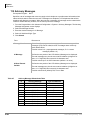
Strata CIX40, CIX100, CIX200 and CIX670 General End User Information
The Strata CIX100, CIX200 or CIX670 Digital Business Telephone System is registered in accordance with
the provisions of Part 68 of the Federal Communications Commission’s Rules and Regulations.
FCC Requirements
Means of Connection: The Federal Communications Commission (FCC) has established rules which
permit the Strata CIX system to be connected directly to the telephone network. Connection points are
provided by the telephone company—connections for this type of customer-provided equipment will not be
provided on coin lines. Connections to party lines are subject to state tariffs.
Incidence of Harm: If the system is malfunctioning, it may also be disrupting the telephone network. The
system should be disconnected until the problem can be determined and repaired. If this is not done, the
telephone company may temporarily disconnect service. If possible, they will notify you in advance, but, if
advance notice is not practical, you will be notified as soon as possible. You will be informed of your right to
file a complaint with the FCC.
Service or Repair: For service or repair, contact your local Toshiba telecommunications distributor. To
obtain the nearest Toshiba telecommunications distributor in your area, log onto www.toshiba.com/taistsd/
pages/support_dealerlocator.html or call (800) 222-5805 and ask for a Toshiba Telecom Dealer.
Telephone Network Compatibility: The telephone company may make changes in its facilities, equipment,
operations, and procedures. If such changes affect the compatibility or use of the Strata CIX100, CIX200 or
CIX670 system, the telephone company will notify you in advance to give you an opportunity to maintain
uninterrupted service.
Notification of Telephone Company: Before connecting a Strata CIX system to the telephone network, the
telephone company may request the following:
1.Your telephone number.
2.FCC and ACTA registration
• Strata CIX100, CIX200 or CIX670 may be configured as a Key, Hybrid or PBX telephone system. The
appropriate configuration for your system is dependent upon your operation of the system.
• If the operation of your system is only manual selection of outgoing lines, it may be registered as a Key
telephone system.
• If your operation requires automatic selection of outgoing lines, such as dial access, Least Cost
Routing, Pooled Line Buttons, etc., the system must be registered as a Hybrid telephone system. In
addition to the above, certain features (tie Lines, Off-premises Stations, etc.) may also require Hybrid
telephone system registration in some areas.
• If you are unsure of your type of operation and/or the appropriate FCC registration number, contact
your local Toshiba telecommunications distributor for assistance.
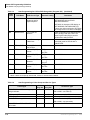
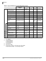
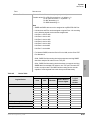
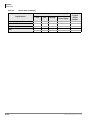
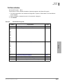
FCC Registration Numbers
SYSTEM
PBX
Fully-protected PBXs
Hybrid
KEY
Fully-protected multifunction systems Fully-protected telephone key systems
CIX40
CJ6PF03BDTCHS402 CJ6MF03BDTCHS40
CJ6KD03BDTCHS40
CIX100
CJ6MUL-35931-PF-E CJ6MUL-35930-MF-E
CJ6MUL-35929-KF-E
CIX200
CJ6PF03BDTCHS192 CJ6MF03BDTCHS192
CJ6KD03BDTCHS192
CIX670
CJ6MUL-35934-PF-E
CJ6MUL-35932-KF-E
CJ6MUL-35930-MF-E
• Ringer equivalence number: 0.3B. The ringer equivalence number (REN) is useful to determine the
quantity of devices which you may connect to your telephone line and still have all of those devices
ring when your number is called. In most areas, but not all, the sum of the RENs of all devices
connected to one line should not exceed five (5.0B). To be certain of the number of devices you may
connect to your line, as determined by the REN, you should contact your local telephone company to
ascertain the maximum REN for your calling area.
3.Network connection information USOC jack required: RJ11/14C,
RJ21/2E/2F/2G/2HX/RJ49C (see Network Requirements in this document). Items 2, 3 and 4 are also
indicated on the equipment label.
4.Authorized Network Parts: 02LS2/GS2, 02RV2-T/O, OL13C/B, T11/12/31/32M, 04DU9-BN/DN/1SN,
02IS5, 04DU9-BN/DN/1SN1ZN
Radio Frequency Interference
Warning: This equipment generates, uses, and can radiate radio frequency energy and if not installed and
used in accordance with the manufacturer’s instruction manual, may cause interference to radio
communications. It has been tested and found to comply with the limits for a Class A computing device
pursuant to Subpart J of Part 15 of FCC Rules, which are designed to provide reasonable protection
against such interference when operated in a commercial environment. Operation of this equipment in a
residential area is likely to cause interference, in which case, the user, at his/her own expense, will be
required to take whatever measures may be required to correct the interference.
Underwriters Laboratory
This system is listed with Underwriters Laboratory (UL). Secondary protection is required, on any
wiring from any telephone that exits the building or is subject to lightning or other electrical
surges, and on DID, OPS, and Tie lines. (Additional information is provided in this manual.)
UL
®
Important Notice — Music-On-Hold
In accordance with U.S. Copyright Law, a license may be required from the American Society of
Composers, Authors and Publishers, or other similar organization, if radio or TV broadcasts are
transmitted through the music-on-hold feature of this telecommunication system. Toshiba America
Information Systems, Inc., strongly recommends not using radio or television broadcasts and hereby
disclaims any liability arising out of the failure to obtain such a license.
CP01, Issue 8, Part I Section 14.1
Notice: The Industry Canada label identifies certified equipment. This certification means that the
equipment meets certain telecommunications network protective, operational and safety requirements as
prescribed in the appropriate Terminal Equipment Technical Requirements document(s). The Department
does not guarantee the Equipment will operate to the user’s satisfaction.
Before installing this equipment, users should ensure that it is permissible to be connected to the facilities
of the local telecommunications company. The equipment must also be installed using an acceptable
method of connection. The customer should be aware that compliance with the above conditions may not
prevent degradation of service in some situations.
Repairs to certified equipment should be coordinated by a representative designated by the supplier. Any
repairs or alterations made by the user to this equipment, or equipment malfunctions, may give the
telecommunications company cause to request the user to disconnect the equipment.
Users should ensure for their own protection that the electrical ground connections of the power utility,
telephone lines and internal metallic water pipe system, if present, are connected together. This precaution
may be particularly important in rural areas.
CAUTION!
Users should not attempt to make such connections themselves, but should
contact the appropriate electric inspection authority, or electrician, as appropriate.
CP01, Issue 8, Part I Section 14.2
Ringer Equivalence Notice: The Ringer Equivalence Number (REN) assigned to each terminal device
provides an indication of the maximum number of terminals allowed to be connected to a telephone
interface. The terminal on an interface may consist of any combination of devices subject only to the
requirement that the sum of the Ringer Equivalence Numbers of all the Devices does not exceed 5.
Hearing Aid Compatibility Notice: The FCC has established rules that require all installed business
telephones be hearing aid compatible. This rule applies to all telephones regardless of the date of
manufacture or installation. There are severe financial penalties which may be levied on the end-user for
non-compliance.
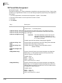
TOSHIBA AMERICA INFORMATION SYSTEMS, INC. (“TAIS”)
Telecommunication Systems Division License Agreement
IMPORTANT: THIS LICENSE AGREEMENT (“AGREEMENT”) IS A LEGAL AGREEMENT BETWEEN YOU (“YOU”) AND TAIS. CAREFULLY READ THIS LICENSE AGREEMENT. USE OF ANY
SOFTWARE OR ANY RELATED INFORMATION (COLLECTIVELY, “SOFTWARE”) INSTALLED ON OR SHIPPED WITH A TAIS DIGITAL SOLUTIONS PRODUCT OR OTHERWISE MADE AVAILABLE TO
YOU BY TAIS IN WHATEVER FORM OR MEDIA, WILL CONSTITUTE YOUR ACCEPTANCE OF THESE TERMS, UNLESS SEPARATE TERMS ARE PROVIDED BY THE SOFTWARE SUPPLIER. IF
YOU DO NOT AGREE WITH THE TERMS OF THIS LICENSE AGREEMENT, DO NOT INSTALL, COPY OR USE THE SOFTWARE AND PROMPTLY RETURN IT TO THE LOCATION FROM WHICH YOU
OBTAINED IT IN ACCORDANCE WITH APPLICABLE RETURN POLICIES. EXCEPT AS OTHERWISE AUTHORIZED IN WRITING BY TAIS, THIS SOFTWARE IS LICENSED FOR DISTRIBUTION
THROUGH TAIS AUTHORIZED CHANNELS ONLY TO END-USERS PURSUANT TO THIS LICENSE AGREEMENT.
1. License Grant. The Software is not sold; it is licensed upon payment of applicable charges. TAIS grants to you a personal, non-transferable and non-exclusive right to use the copy of the Software
provided under this License Agreement. You agree you will not copy the Software except as necessary to use it on one TAIS system at a time at one location. Modifying, translating, renting, copying,
distributing, printing, sublicensing, transferring or assigning all or part of the Software, or any rights granted hereunder, to any other persons and removing any proprietary notices, labels or marks from the
Software is strictly prohibited except as permitted by applicable law; you agree violation of such restrictions will cause irreparable harm to TAIS and provide grounds for injunctive relief, without notice,
against you or any other person in possession of the Software. You and any other person whose possession of the software violates this License Agreement shall promptly surrender possession of the
Software to TAIS, upon demand. Furthermore, you hereby agree not to create derivative works based on the Software. TAIS reserves the right to terminate this license and to immediately repossess the
software in the event that you or any other person violates this License Agreement. Execution of the Software for any additional capabilities require a valid run-time license.
2. Intellectual Property. You acknowledge that no title to the intellectual property in the Software is transferred to you. You further acknowledge that title and full ownership rights to the Software will remain
the exclusive property of TAIS and/or its suppliers, and you will not acquire any rights to the Software, except the license expressly set forth above. You will not remove or change any proprietary notices
contained in or on the Software. The Software is protected under US patent, copyright, trade secret, and/or other proprietary laws, as well as international treaties. Any transfer, use, or copying of the
software in violation of the License Agreement constitutes copyright infringement. You are hereby on notice that any transfer, use, or copying of the Software in violation of this License Agreement constitutes
a willful infringement of copyright.
3. No Reverse Engineering. You agree that you will not attempt, and if you employ employees or engage contractors, you will use your best efforts to prevent your employees and contractors from
attempting to reverse compile, reverse engineer, modify, translate or disassemble the Software in whole or in part. Any failure to comply with the above or any other terms and conditions contained herein
will result in the automatic termination of this license and the reversion of the rights granted hereunder back to TAIS.
4. Limited Warranty. THE SOFTWARE IS PROVIDED “AS IS” WITHOUT WARRANTY OF ANY KIND. TO THE MAXIMUM EXTENT PERMITTED BY APPLICABLE LAW, TAIS AND ITS SUPPLIERS
DISCLAIM ALL WARRANTIES WITH REGARD TO THE SOFTWARE, EITHER EXPRESS OR IMPLIED, INCLUDING, BUT NOT LIMITED TO, THE WARRANTY OF NON-INFRINGEMENT OF THIRD
PARTY RIGHTS, THE WARRANTY OF YEAR 2000 COMPLIANCE, AND THE IMPLIED WARRANTIES OF MERCHANTABILITY AND FITNESS FOR A PARTICULAR PURPOSE. THE ENTIRE RISK AS
TO THE QUALITY AND PERFORMANCE OF THE SOFTWARE IS WITH YOU. NEITHER TAIS NOR ITS SUPPLIERS WARRANT THAT THE FUNCTIONS CONTAINED IN THE SOFTWARE WILL MEET
YOUR REQUIREMENTS OR THAT THE OPERATION OF THE SOFTWARE WILL BE UNINTERRUPTED OR ERROR-FREE. HOWEVER, TAIS WARRANTS THAT ANY MEDIA ON WHICH THE
SOFTWARE IS FURNISHED IS FREE FROM DEFECTS IN MATERIAL AND WORKMANSHIP UNDER NORMAL USE FOR A PERIOD OF NINETY (90) DAYS FROM THE DATE OF DELIVERY TO
YOU.
5. Limitation Of Liability. TAIS’ ENTIRE LIABILITY AND YOUR SOLE AND EXCLUSIVE REMEDY UNDER THIS LICENSE AGREEMENT SHALL BE AT TAIS’ OPTION REPLACEMENT OF THE MEDIA OR
REFUND OF THE PRICE PAID. TO THE MAXIMUM EXTENT PERMITTED BY APPLICABLE LAW, IN NO EVENT SHALL TAIS OR ITS SUPPLIERS BE LIABLE TO YOU FOR ANY CONSEQUENTIAL,
SPECIAL, INCIDENTAL OR INDIRECT DAMAGES FOR PERSONAL INJURY, LOSS OF BUSINESS PROFITS, BUSINESS INTERRUPTION, LOSS OF BUSINESS INFORMATION/DATA, OR ANY
OTHER PECUNIARY LOSS OF ANY KIND ARISING OUT OF THE USE OR INABILITY TO USE THE SOFTWARE, EVEN IF TAIS OR ITS SUPPLIER HAS BEEN ADVISED OF THE POSSIBILITY OF
SUCH DAMAGES. IN NO EVENT SHALL TAIS OR ITS SUPPLIERS BE LIABLE FOR ANY CLAIM BY A THIRD PARTY.
6. State/Jurisdiction Laws. SOME STATES/JURISDICTIONS DO NOT ALLOW THE EXCLUSION OF IMPLIED WARRANTIES OR LIMITATIONS ON HOW LONG AN IMPLIED WARRANTY MAY LAST, OR
THE EXCLUSION OR LIMITATION OF INCIDENTAL OR CONSEQUENTIAL DAMAGES, SO SUCH LIMITATIONS OR EXCLUSIONS MAY NOT APPLY TO YOU. THIS LIMITED WARRANTY GIVES YOU
SPECIFIC RIGHTS AND YOU MAY ALSO HAVE OTHER RIGHTS WHICH VARY FROM STATE/JURISDICTION TO STATE/JURISDICTION.
7. Export Laws. This License Agreement involves products and/or technical data that may be controlled under the United States Export Administration Regulations and may be subject to the approval of the
United States Department of Commerce prior to export. Any export, directly or indirectly, in contravention of the United States Export Administration Regulations, or any other applicable law, regulation or
order, is prohibited.
8. Governing Law. This License Agreement will be governed by the laws of the State of California, United States of America, excluding its conflict of law provisions.
9. United States Government Restricted Rights. The Software is provided with Restricted Rights. The Software and other materials provided hereunder constitute Commercial Computer Software and
Software Documentation and Technical Data related to Commercial Items. Consistent with F.A.R. 12.211 and 12.212 they are licensed to the U.S. Government under, and the U.S. Government’s rights
therein are restricted pursuant to, the vendor’s commercial license.
10. Severability. If any provision of this License Agreement shall be held to be invalid, illegal or unenforceable, the validity, legality and enforceability of the remaining provisions hereof shall not in any way
be affected or impaired.
11. No Waiver. No waiver of any breach of any provision of this License Agreement shall constitute a waiver of any prior, concurrent or subsequent breach of the same or any other provisions hereof, and no
waiver shall be effective unless made in writing and signed by an authorized representative of the waiving party.
12. Supplier Software. The Software may include certain software provided by TAIS suppliers. In such event, you agree that such supplier may be designated by TAIS as a third party beneficiary of TAIS with
rights to enforce the Agreement with respect to supplier’s software.
YOU ACKNOWLEDGE THAT YOU HAVE READ THIS LICENSE AGREEMENT AND THAT YOU UNDERSTAND ITS PROVISIONS. YOU AGREE TO BE BOUND BY ITS TERMS AND CONDITIONS. YOU
FURTHER AGREE THAT THIS LICENSE AGREEMENT CONTAINS THE COMPLETE AND EXCLUSIVE AGREEMENT BETWEEN YOU AND TAIS AND SUPERSEDES ANY PROPOSAL OR PRIOR
AGREEMENT, ORAL OR WRITTEN, OR ANY OTHER COMMUNICATION RELATING TO THE SUBJECT MATTER OF THIS LICENSE AGREEMENT.
Toshiba America Information Systems, Inc.
Telecommunication Systems Division
9740 Irvine Boulevard
Irvine, California 92618-1697
United States of America
DSD 020905
5932
T
Toshiba America Information Systems, Inc.
Telecommunication Systems Division
End-User Limited Warranty
Toshiba America Information Systems, Inc., (“TAIS”) warrants that this telephone equipment manufactured by
Toshiba (except for fuses, lamps, and other consumables) will, upon delivery by TAIS or an authorized TAIS
dealer to a retail customer in new condition, be free from defects in material and workmanship for twenty-four (24)
months after delivery, except as otherwise provided by TAIS in the TAIS warranty accompanying the products or
posted on TAIS’s website. Products which are not manufactured by Toshiba but are purchased from Toshiba, will
be subject to the warranty provisions provided by the equipment manufacturer, unless TAIS notifies the end-user
of any additional warranty provisions in writing.
This warranty is void (a) if the equipment is used under other than normal use and maintenance conditions, (b) if
the equipment is modified or altered, unless the modification or alteration is expressly authorized by TAIS, (c) if
the equipment is subject to abuse, neglect, lightning, electrical fault, or accident, (d) if the equipment is repaired
by someone other than TAIS or an authorized TAIS dealer, (e) if the equipment’s serial number is defaced or missing, or (f) if the equipment is installed or used in combination or in assembly with products not supplied by TAIS
and which are not compatible or are of inferior quality, design, or performance.
The sole obligation of TAIS or Toshiba Corporation under this warranty, or under any other legal obligation with
respect to the equipment, is the repair or replacement of such defective or missing parts as are causing the malfunction by TAIS or its authorized dealer with new or refurbished parts (at their option). If TAIS or one of its authorized dealers does not replace or repair such parts, the retail customer’s sole remedy will be a refund of the price
charged by TAIS to its dealers for such parts as are proven to be defective, and which are returned to TAIS through
one of its authorized dealers within the warranty period and no later than thirty (30) days after such malfunction,
whichever first occurs.
Under no circumstances will the retail customer or any user or dealer or other person be entitled to any direct,
special, indirect, consequential, or exemplary damages, for breach of contract, tort, or otherwise. Under no circumstances will any such person be entitled to any sum greater than the purchase price paid for the item of equipment
that is malfunctioning.
To obtain service under this warranty, the retail customer must bring the malfunction of the machine to the attention of one of TAIS’ authorized dealers within the applicable warranty period and no later than thirty (30) days
after such malfunction, whichever first occurs. Failure to bring the malfunction to the attention of an authorized
TAIS dealer within the prescribed time results in the customer being not entitled to warranty service.
THERE ARE NO OTHER WARRANTIES FROM EITHER TOSHIBA AMERICA INFORMATION SYSTEMS,
INC., OR TOSHIBA CORPORATION WHICH EXTEND BEYOND THE FACE OF THIS WARRANTY. ALL
OTHER WARRANTIES, EXPRESS OR IMPLIED, INCLUDING THE WARRANTIES OF MERCHANTABILITY,
FITNESS FOR A PARTICULAR PURPOSE, AND FITNESS FOR USE, ARE EXCLUDED.
No TAIS dealer and no person other than an officer of TAIS may extend or modify this warranty. No such modification or extension is effective unless it is in writing and signed by the Vice President and General Manager, Telecommunication Systems Division.
WARRANTIES FOR NON-TOSHIBA BRANDED THIRD
PARTY PRODUCTS
A valuable element of Toshiba’s product strategy is to offer our customers a complete product portfolio. To
provide this value to our customers at the most optimal prices, we offer both Toshiba-branded and
third-party manufactured products that support our Toshiba Strata CIX product portfolio. Similar to
other resellers of software, hardware and peripherals, these third-party manufactured products carry
warranties independent of our Toshiba limited warranty provided with our Toshiba-branded products.
Customers should note that third-party manufacturer warranties vary from product to product and are
covered by the warranties provided through the original manufacturer and passed on intact to the
purchaser by Toshiba. Customers should consult their product documentation for third-party warranty
information specific to third-party products. More information may also be available in some cases
from the manufacturer’s public website.
While Toshiba offers a wide selection of software, hardware and peripheral products, we do not specifically
test or guarantee that the third-party products we offer work under every configuration with any or all of
the various models of the Toshiba Strata CIX. Toshiba does not endorse, warrant nor assume any
liability in connection with such third party products or services. If you have questions about
compatibility, we recommend and encourage you to contact the third-party software, hardware and
peripheral product manufacturer directly.
This page is intentionally left blank.
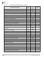
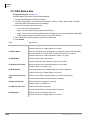
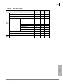
Contents
Contents
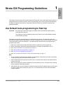
Chapter 1 – Strata CIX Programming Guidelines
Use Default Auto-programming to Start Up........................................................................................ 1-1
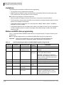
Limitations .................................................................................................................................... 1-2
Station and BIOU Auto-programming .......................................................................................... 1-2
Station PDN Auto-programming................................................................................................... 1-3
CO Line Auto-programming ......................................................................................................... 1-3
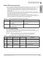
MIPU / GIPU / LIPU / BIPU Settings ............................................................................................ 1-6
CIX Processor NIC Interface TCP/IP Auto-programming ............................................................ 1-9
Default Feature Access Codes .................................................................................................. 1-10
Plan Your System Requirements ............................................................................................... 1-11
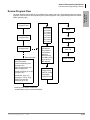
Program the CIX for First Time .................................................................................................. 1-11
Review Program Flow ................................................................................................................ 1-13
Identify Program Sequences...................................................................................................... 1-14
Station Setup.............................................................................................................................. 1-14
Trunk Setup – Analog ................................................................................................................ 1-15
Trunk Setup – T1 ....................................................................................................................... 1-15
Trunk Setup – ISDN PRI ............................................................................................................ 1-16
Trunk Setup – ISDN PRI - Strata Net......................................................................................... 1-16
SIP Trunking .............................................................................................................................. 1-17
Miscellaneous ............................................................................................................................ 1-17
Chapter 2 – Strata eManager ®
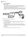
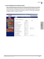
Introduction......................................................................................................................................... 2-1
eManager ........................................................................................................................................... 2-1
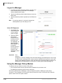
Network eManager® Introduction....................................................................................................... 2-2
Advantages of Network eManager............................................................................................... 2-2
Network eManager Main Menu .................................................................................................... 2-3
Equipment Setup.......................................................................................................................... 2-4
Add Equipment Window............................................................................................................... 2-4
Connecting To Multiple CIX Systems........................................................................................... 2-5
Connection Mode ......................................................................................................................... 2-5
Add New Stations......................................................................................................................... 2-5
MAS Licensing ............................................................................................................................. 2-5
Add New User .............................................................................................................................. 2-6
The Network eManager Toolbar Setup Menu .............................................................................. 2-7
Network eManager Command Structure...................................................................................... 2-8
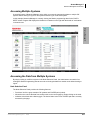
Accessing Multiple Systems......................................................................................................... 2-9
Accessing the Data from Multiple Systems.................................................................................. 2-9
Backing Up The Database On Multiple CIX Systems ................................................................ 2-10
Updating the Software On Multiple CIX Systems....................................................................... 2-11
Strata CIX Programming Vol.1
05/08
i
Contents
Creating Network DNs in Multiple Systems ............................................................................... 2-11
Install eManager ............................................................................................................................... 2-12
eManager PC Minimum Requirements ...................................................................................... 2-12
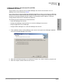
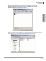
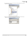
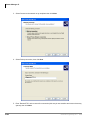
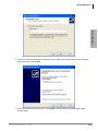
Install or Upgrade eManager Software ...................................................................................... 2-13
eManager Installation/Upgrade Procedure ................................................................................ 2-14
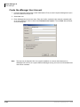
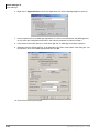
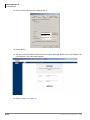
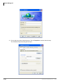
Create the eManager User Account........................................................................................... 2-20
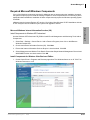
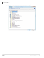
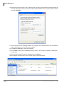
Required Microsoft Windows Components ................................................................................ 2-33
Verify the CIX System IP Address ............................................................................................. 2-43
Access eManager ...................................................................................................................... 2-43
Connect to eManager................................................................................................................. 2-44
Set up Modem Connection (Optional)........................................................................................ 2-45
Log on to eManager ................................................................................................................... 2-46
Using the eManager Dial-up Modem ......................................................................................... 2-46
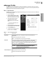
eManager Profile .............................................................................................................................. 2-47
Backup Database Utility ............................................................................................................. 2-51
Restore Database Utility ............................................................................................................ 2-52
Options ............................................................................................................................................. 2-52
eManager Main Screen .................................................................................................................... 2-53
Program Menu ........................................................................................................................... 2-53
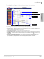
eManager Sub-screens .................................................................................................................... 2-54
Special Buttons .......................................................................................................................... 2-56
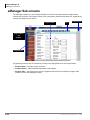
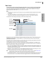
Table Views................................................................................................................................ 2-57
Help Topics/Context Help .......................................................................................................... 2-58
eManager Data Import / Export Features ......................................................................................... 2-65
eManager DID/DNIS Assignments - Import/Export.................................................................... 2-65
eManager Station Directory - Import/Export .............................................................................. 2-69
Speed Dial Export/Import ........................................................................................................... 2-71
eManager Network Calling Number Upload............................................................................... 2-76
eManager DESI integration / Telephone Keystrip Printing......................................................... 2-79
eManager Data Download ........................................................................................................ 2-79
DESI Label Printer Software ...................................................................................................... 2-80
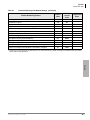
Chapter 3 – Licenses
Upgrading a CTX100 or CTX670 System from R3.1 to R4.......................................................... 3-2
R4 License Generation For CTX100 and CTX670....................................................................... 3-2
System License Example............................................................................................................. 3-3
License Simplification................................................................................................................... 3-4
License Display Screen Enhancement ........................................................................................ 3-7
MAS Licensing.................................................................................................................................... 3-8
Access Main MAS Licensing Screen ........................................................................................... 3-8
Upload Licenses........................................................................................................................... 3-9
Issue Licenses ............................................................................................................................. 3-9
Activate Licenses ......................................................................................................................... 3-9
Delete Licenses.......................................................................................................................... 3-10
View Licenses ............................................................................................................................ 3-10
View Current Licenses ............................................................................................................... 3-10
ii
Strata CIX Programming Vol.1
05/08
Contents
Chapter 4 – System
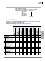
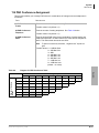
100 Cabinet Slot PCB Assignments............................................................................................. 4-1
Dial Number Plan ............................................................................................................................... 4-2
102 Flexible Access Codes.......................................................................................................... 4-3
Creating New Feature Codes....................................................................................................... 4-4
Flexible Numbering Default Settings............................................................................................ 4-4
117 Public Dial Plan Digit Analysis .............................................................................................. 4-8
103 Class of Service .................................................................................................................... 4-9
104 System Timer ...................................................................................................................... 4-12
105 System Data........................................................................................................................ 4-15
System Call Forward ........................................................................................................................ 4-21
500 / 504 System Call Forward Assignment .............................................................................. 4-21
System Call Forward Copy ........................................................................................................ 4-22
System Call Forward Table View ............................................................................................... 4-22
501 System Speed Dial.............................................................................................................. 4-23
System Speed Dial Table View.................................................................................................. 4-23
Day Night Service............................................................................................................................. 4-24
112 Day/Night Mode Calendar................................................................................................... 4-24
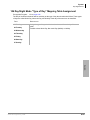
106 Day/Night Mode “Type of Day” Mapping Table Assignment ............................................... 4-25
113 Day/Night Mode Schedule per Tenant Assignment ............................................................ 4-26
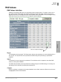
PAD Values ...................................................................................................................................... 4-27
PAD Values Interface................................................................................................................. 4-27
PAD Table.................................................................................................................................. 4-28
107 PAD Table Assignment ....................................................................................................... 4-28
108 PAD Group Assignment ...................................................................................................... 4-30
114 PAD Conference Assignment ............................................................................................. 4-31
110 Password ............................................................................................................................ 4-32
109 Music on Hold ..................................................................................................................... 4-33
I/O Device .................................................................................................................................. 4-34
803 SMDR SMDI CTI Port Assignments.................................................................................... 4-34
801 Network Jack LAN Device Assignment............................................................................... 4-37
804 BSIS RS-232 Serial Port Setup........................................................................................... 4-39
115 Advisory Messages ............................................................................................................. 4-40
116 Data Initialize....................................................................................................................... 4-41
120 Tenant Data Assignment..................................................................................................... 4-42
Chapter 5 – Station
Assignment......................................................................................................................................... 5-1
Basic/200 Station Data................................................................................................................. 5-1
204 DKT Parameters ................................................................................................................. 5-14
214 DSS Console Assignment................................................................................................... 5-23
206 Phantom DN........................................................................................................................ 5-30
209 Hunt Group.......................................................................................................................... 5-32
218 Station Hunt Assignments................................................................................................... 5-34
Hunt Group Table View.............................................................................................................. 5-35
Paging Group ............................................................................................................................. 5-36
210 Pickup Group ...................................................................................................................... 5-37
Multiple Call Group..................................................................................................................... 5-38
517 Multiple Calling Group Assignment ..................................................................................... 5-39
Strata CIX Programming Vol.1
05/08
iii
Contents
518 Multiple Calling Members Assignment ................................................................................ 5-40
516 Station Speed Dial .............................................................................................................. 5-41
ISDN ................................................................................................................................................. 5-43
202 ISDN BRI Station ................................................................................................................ 5-43
217 ISDN Station Data............................................................................................................... 5-48
Setup Wizards .................................................................................................................................. 5-50
PDN Range Setup Wizard ......................................................................................................... 5-50
Multiple DN Assignment Wizard................................................................................................. 5-50
VMID Range............................................................................................................................... 5-51
Chapter 6 – Trunks
304 Incoming Line Group............................................................................................................. 6-1
304 Incoming Line Group Assignment ......................................................................................... 6-2
306 Outgoing Line Groups ........................................................................................................... 6-5
300 Trunk Assignment ................................................................................................................. 6-7
313 Caller ID .............................................................................................................................. 6-10
308 Trunk Timer......................................................................................................................... 6-11
310 DIT Assignment................................................................................................................... 6-13
309 Direct Inward Dialing ........................................................................................................... 6-15
318 DID Intercept Assignments ................................................................................................. 6-18
Service.............................................................................................................................................. 6-21
311 DISA Security Code ............................................................................................................ 6-21
319 Intercept Treatment............................................................................................................. 6-22
315 T1 Trunk Card ..................................................................................................................... 6-23
DID/DNIS Table View................................................................................................................. 6-24
ISDN ................................................................................................................................................. 6-25
317 ISDN BRI Trunk .................................................................................................................. 6-25
302 Strata Net (PRI) and Strata Net IP (QSIG).......................................................................... 6-29
Call-by-Call................................................................................................................................. 6-34
320 B Channel ........................................................................................................................... 6-36
316 Shared D Channel............................................................................................................... 6-37
Calling Number .......................................................................................................................... 6-38
Trunk DID/DNIS Setup Wizard ......................................................................................................... 6-40
325 Strata Net IP Trunk Assignment.......................................................................................... 6-44
Chapter 7 – Attendant
404 Attendant Group Assignment ................................................................................................ 7-1
400 Emergency Call Destination Assignment .............................................................................. 7-2
Chapter 8 –
IP Telephone Programming
IP Telephone Setup............................................................................................................................ 8-1
CIX IP Telephone Programming .................................................................................................. 8-1
VLAN Setup........................................................................................................................................ 8-3
Using the VLAN Wizard ............................................................................................................... 8-3
Enable VLAN on the xIPU............................................................................................................ 8-3
CIX IP Telephone Programming Guidelines....................................................................................... 8-4
Basic CIX IP Setup Using WinAdmin ........................................................................................... 8-4
IP Telephone Installation and Network Connection Setup ................................................................. 8-5
150 System IP Data ..................................................................................................................... 8-6
iv
Strata CIX Programming Vol.1
05/08
Contents
151 BIPU Configuration ............................................................................................................... 8-9
152 Voice Packet Configuration Table Assignment ................................................................... 8-10
161 MIPU/LIPU/GIPU Configuration .......................................................................................... 8-12
250 IP Telephone (Station) Data Assignment............................................................................ 8-14
260 Full IP Station Assignment .................................................................................................. 8-19
274 Remote Node IPU IP Address Assignment......................................................................... 8-25
IP Mobility Programming .................................................................................................................. 8-26
Requirements............................................................................................................................. 8-26
More IP Telephone DNs than xIPU ports................................................................................... 8-26
Feature Administration/Programming............................................................................................... 8-27
IP Mobility Programming Steps.................................................................................................. 8-28
Compatibility............................................................................................................................... 8-28
BIPU-M and IPT Program Update .................................................................................................... 8-29
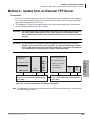
FTP Server Information.............................................................................................................. 8-29
BIPU Program Update ............................................................................................................... 8-30
IPT Program Update .................................................................................................................. 8-32
Chapter 9 – Services
540 Pilot DN Assignment ............................................................................................................. 9-1
579 System Voice Mail Data ........................................................................................................ 9-3
580 Voice Mail Port Data ............................................................................................................. 9-5
Destination Restriction/Least Cost Routing ........................................................................................ 9-6
DR Overview ................................................................................................................................ 9-6
Destination Restriction Guide Page ........................................................................................... 9-10
DR Dialing Setup........................................................................................................................ 9-10
DR Digit Table Setup ................................................................................................................. 9-10
DR Class of Service Setup......................................................................................................... 9-11
LCR Overview .................................................................................................................................. 9-12
LCR Analysis Process................................................................................................................ 9-12
DR .............................................................................................................................................. 9-12
Route Analysis ........................................................................................................................... 9-13
Time of Day................................................................................................................................ 9-13
Connection ................................................................................................................................. 9-13
LCR Guide Page ........................................................................................................................ 9-13
LCR Dialing Setup...................................................................................................................... 9-14
LCR Route Plan Setup............................................................................................................... 9-14
LCR Day of Week and Time Zone Setup................................................................................... 9-15
LCR COS and Station Setup...................................................................................................... 9-15
LCR/DR ............................................................................................................................................ 9-16
LCR Assignment ........................................................................................................................ 9-16
520 LCR Local Route Plan Assignment..................................................................................... 9-16
521 LCR Route Plan Digit Analysis Assignment........................................................................ 9-17
522 LCR Exception Number Route Plans.................................................................................. 9-17
Route Define .............................................................................................................................. 9-18
524 Route Table to Route Definition Assignment ...................................................................... 9-18
525 LCR Route Definition Assignment....................................................................................... 9-19
526 Modified Digits Table Assignment....................................................................................... 9-19
Route Schedule.......................................................................................................................... 9-20
523 LCR Route Plan Schedule Assignment .............................................................................. 9-20
528 LCR Public Day of Week Mapping Table............................................................................ 9-21
Strata CIX Programming Vol.1
05/08
v
Contents
Public Holidays and LCR Time Zones ....................................................................................... 9-22
527 LCR Holiday Table .............................................................................................................. 9-22
529 LCR Route Plan Time Zone Assignment ............................................................................ 9-22
530 DR LCR Screening Table Assignment................................................................................ 9-23
531 DR Screening Table for OLG .............................................................................................. 9-24
Destination Restriction...................................................................................................................... 9-25
532 DR Table Allow/Deny Definition .......................................................................................... 9-25
533 DR Level Table Assignment................................................................................................ 9-25
534 DRL Exception Table Assignment ...................................................................................... 9-26
111 DR Level ............................................................................................................................. 9-26
DRL Table View ......................................................................................................................... 9-26
Centrex/PBX Screening Table View .......................................................................................... 9-26
Account Codes ................................................................................................................................. 9-27
570 Account Code Digit Length ................................................................................................. 9-28
506 Verified Account Codes....................................................................................................... 9-29
571 Exception Numbers for Forced Account Codes .................................................................. 9-29
509 DR Override by System Speed Dial.................................................................................... 9-30
510 COS Override Assignment.................................................................................................. 9-31
656 Local Node ID Assignment.................................................................................................. 9-32
670 Remote Node Data Assignment.......................................................................................... 9-33
651 Private Routing Plan Analysis ............................................................................................. 9-34
Private Route Choice Definition........................................................................................................ 9-34
653 Private Route Choice Table Assignment ............................................................................ 9-35
654 Private Route Definition Table Assignment......................................................................... 9-35
655 Private Network Digit Modification Table Assignment......................................................... 9-35
Mapping............................................................................................................................................ 9-36
657 Network COS Mapping Table ............................................................................................. 9-36
658/659/660 Network DRL/FRL/QPL Mapping Tables .............................................................. 9-37
661 Network DN Table Assignment ........................................................................................... 9-37
219 Network DSS Notify Data Delete ........................................................................................ 9-38
Strata Net Over IP ............................................................................................................................ 9-39
671 IP Address Convert Table ................................................................................................... 9-39
672 Node ID Detail Information.................................................................................................. 9-40
Miscellaneous................................................................................................................................... 9-42
SMDR ............................................................................................................................................... 9-42
512 SMDR for System Assignment............................................................................................ 9-42
513 SMDR for ILG Assignment.................................................................................................. 9-43
514 SMDR for OLG Assignment ................................................................................................ 9-43
577 Caller History....................................................................................................................... 9-44
650 Behind Centrex Assignment................................................................................................ 9-45
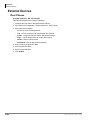
External Devices............................................................................................................................... 9-46
Door Phones .............................................................................................................................. 9-46
507 Door Phone Assignment ..................................................................................................... 9-47
576 Door Phone Night Ring Over External Page ...................................................................... 9-49
508 Door Lock Control Assignment ........................................................................................... 9-49
515 View BIOU Control Relay Assignments .............................................................................. 9-51
503 Paging Devices Group Assignments................................................................................... 9-52
550 Enhanced 911 Emergency Call Group................................................................................ 9-52
vi
Strata CIX Programming Vol.1
05/08
Contents
Chapter 10 – Operation
System Setup ................................................................................................................................... 10-1
900 CIX Restart.......................................................................................................................... 10-2
901 Display Version ................................................................................................................... 10-3
915 Regional Selection .............................................................................................................. 10-3
902 Set Time and Date .............................................................................................................. 10-4
121 Automatic Day Light Savings Time Change........................................................................ 10-4
908 Secure Digital and SmartMedia .......................................................................................... 10-5
Secure Digital or SmartMedia Card ........................................................................................... 10-5
CIX SM/SD Folders.................................................................................................................... 10-7
911 Remote Program Update .................................................................................................... 10-8
CIX Software Update Files......................................................................................................... 10-8
CIX Software Identification......................................................................................................... 10-8
Remote Update for Release 4.................................................................................................... 10-8
Remote Update Operation ......................................................................................................... 10-9
System Turn-on and Start-up Time............................................................................................ 10-9
Programming Data File Name.................................................................................................. 10-10
Remote Update for Release 1 ~ 3 ........................................................................................... 10-10
910 Data Backup...................................................................................................................... 10-15
916 IP Configuration ................................................................................................................ 10-16
FTP User Accounts ........................................................................................................................ 10-17
File Information............................................................................................................................... 10-17
Community Name........................................................................................................................... 10-18
909 MAC Address .................................................................................................................... 10-19
License Control............................................................................................................................... 10-20
License Issue ........................................................................................................................... 10-20
License Activate ....................................................................................................................... 10-21
License Information.................................................................................................................. 10-21
Alarm Control.................................................................................................................................. 10-23
System Alarm Control (Program 919) ...................................................................................... 10-23
Alarm Control for Slot (Program 920)....................................................................................... 10-24
921 Traffic Measurement................................................................................................................ 10-25
Program 922 Specified Traffic Reports .................................................................................... 10-26
Trap Destinations (IP Trap Setup).................................................................................................. 10-27
IP Trap Setup ........................................................................................................................... 10-27
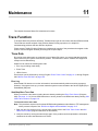
Chapter 11 – Maintenance
Trace Function.................................................................................................................................. 11-1
Trace Data ................................................................................................................................. 11-1
Event Trace Control.......................................................................................................................... 11-3
903 Start/Stop Trace .................................................................................................................. 11-3
904 ISDN Trace Location........................................................................................................... 11-4
905 All ISDN Trunk Trace Selection .......................................................................................... 11-4
906 Change Trace Selection...................................................................................................... 11-4
Error Alarm Log ................................................................................................................................ 11-5
907 System Admin Log .............................................................................................................. 11-5
Memory Access Operation ............................................................................................................... 11-6
Components ..................................................................................................................................... 11-6
Strata CIX Programming Vol.1
05/08
vii
Contents
Chapter 12 – Tools and Profile
Tools................................................................................................................................................. 12-1
Download ................................................................................................................................... 12-1
Chapter 13 – Telephone Button Programming
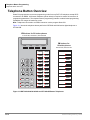
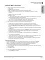
Telephone Button Overview ............................................................................................................. 13-2
Telephone Button Commands ................................................................................................... 13-3
Button Programming Procedure................................................................................................. 13-5
900 Series Programs........................................................................................................................ 13-6
System Initialize ......................................................................................................................... 13-6
Display Version .......................................................................................................................... 13-7
Set Time and Date ..................................................................................................................... 13-9
ISDN Trace Location................................................................................................................ 13-11
All ISDN Trunk Trace ............................................................................................................... 13-12
Event Trace Side Change ........................................................................................................ 13-12
System Admin Log ................................................................................................................... 13-13
Format/Unmount Secure Digital/SmartMedia .......................................................................... 13-14
MAC Address (System Serial Number).................................................................................... 13-15
Data Backup............................................................................................................................. 13-15
Program Update....................................................................................................................... 13-17
Make Busy Control................................................................................................................... 13-18
Regional Selection ................................................................................................................... 13-19
IP Configuration ....................................................................................................................... 13-20
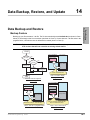
Chapter 14 – Data Backup, Restore, and Update
Data Backup and Restore ................................................................................................................ 14-1
Backup Feature.......................................................................................................................... 14-1
Restore Feature ......................................................................................................................... 14-2
Remote Update ................................................................................................................................ 14-3
Remote Update Operation ......................................................................................................... 14-3
System Turn-on and Start-up Time .................................................................................................. 14-3
R3.0 and Earlier Data Backup .......................................................................................................... 14-4
Backup Progress and Completion Indicators ............................................................................. 14-4
Restoring Programmed Data............................................................................................................ 14-5
Local Update .................................................................................................................................... 14-5
Prerequisites for CIX100, CIX200 and CIX670 Local Update.................................................... 14-5
CIX Software Update Files......................................................................................................... 14-5
CIX Software Identification......................................................................................................... 14-6
Strata CIX670 Local Update ...................................................................................................... 14-9
Appendix A – Applications Guide
Voice Mail Set Up ...............................................................................................................................A-1
Analog Ports.................................................................................................................................A-1
Digital Ports..................................................................................................................................A-2
Telephone Station Ports...............................................................................................................A-2
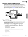
Networking Multiple Voice Mail Systems............................................................................................A-3
Call Record and Soft Keys ...........................................................................................................A-3
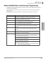
Strata CIX BRI Video Conferencing Programming.............................................................................A-5
IP Telephone Quality of Service (QoS) Programming........................................................................A-6
viii
Strata CIX Programming Vol.1
05/08
Contents
General QoS Adjustments ...........................................................................................................A-6
Priority Control Adjustments.........................................................................................................A-7
Networking..........................................................................................................................................A-8
Strata Net Private Networking......................................................................................................A-8
QSIG ............................................................................................................................................A-8
Node ID ........................................................................................................................................A-8
Network Directory Number...........................................................................................................A-8
Network Feature Access Code ....................................................................................................A-9
Digit Manipulation.........................................................................................................................A-9
Traveling Class Mark .................................................................................................................A-10
Path Replacement......................................................................................................................A-10
Coordinated Numbering Plan.....................................................................................................A-10
Station Message Detail Recording (SMDR)...............................................................................A-11
Centralized Voice Mail ...............................................................................................................A-12
Centralized Attendant.................................................................................................................A-12
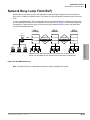
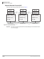
Network Busy Lamp Field (BLF).......................................................................................................A-13
Network Attendant Console BLF................................................................................................A-14
Network DSS/BLF for Digital Telephones ..................................................................................A-16
Network DSS..............................................................................................................................A-18
Network Feature Content .................................................................................................................A-20
Configuration..............................................................................................................................A-21
Strata Net Programming Overview...................................................................................................A-21
Strata Net over IP Programming Guidelines ....................................................................................A-22
Example .....................................................................................................................................A-23
IP StrataNet Node Setup for CIX......................................................................................................A-24
Appendix B – Software and Firmware Updates
IP Telephone, MIPU, GIPU, LIPU and BIPU Firmware Update Procedures ......................................B-1
Download Firmware Update Files ................................................................................................B-2
Copy the IP Update Files to eManager Folders ...........................................................................B-2
Copy the IP Update Files to the SM/SD Media Card ...................................................................B-3
LIPU Update.................................................................................................................................B-4
BIPU Update ................................................................................................................................B-5
IP Telephone Update ..................................................................................................................B-6
LIPU Update.................................................................................................................................B-8
BIPU Update ................................................................................................................................B-8
IP Telephone Update ...................................................................................................................B-9
Update From an FTP Directory on the eManager PC................................................................B-10
LIPU Update...............................................................................................................................B-11
BIPU Update ..............................................................................................................................B-12
IPT20X0 and IPT2008 Update ...................................................................................................B-13
Appendix C – SIP Trunking
Requirements .....................................................................................................................................C-1
SIP Trunking Network Configuration Example ...................................................................................C-2
Configure CBeyond SIP Trunks .........................................................................................................C-3
Programming for CBeyond SIP Trunks ..............................................................................................C-4
Programming the Incoming Line Group .......................................................................................C-5
Programming the Outgoing Line Group .......................................................................................C-6
Creating the Channel Group ........................................................................................................C-7
Strata CIX Programming Vol.1
05/08
ix
Contents
Service Definition .........................................................................................................................C-8
Service Assignment .....................................................................................................................C-9
URI Programming ......................................................................................................................C-10
Configuring the MIPU/GIPU .......................................................................................................C-11
Configuring the MIPU/GIPU continued ......................................................................................C-12
Configure ABS SIP Trunks ...............................................................................................................C-13
Programming for ABS SIP Trunks....................................................................................................C-14
Programming the MIPU/GIPU card............................................................................................C-14
Programming the Incoming Line Group .....................................................................................C-15
Programming the Outgoing Line Group .....................................................................................C-16
Creating the Channel Group ......................................................................................................C-17
Service Definition .......................................................................................................................C-18
Service Assignment ...................................................................................................................C-19
URI Programming ......................................................................................................................C-20
Configuring the MIPU/GIPU .......................................................................................................C-21
Configuring the MIPU/GIPU continued ......................................................................................C-22
x
Strata CIX Programming Vol.1
05/08
Introduction
This manual provides information required to program the Strata® CIX™ business telephone
systems using Toshiba’s eManager™ programming interface and the 900 series Button
Programming.
Important!
Whenever the CIX100 is mentioned in this book, it applies to both the
CIX100-S and CIX100, unless specified otherwise. Whenever the CIX is
mentioned in this book, it applies to all CIX40, CIX100, CIX100-S, CIX200
and CIX670 systems, unless specified otherwise.
Important!
Do not downgrade to previous versions of CIX or CTX software. Downward
compatibility of CIX database is not supported. Toshiba recommends
keeping the current database for emergency situations. We guarantee
upward compatibility of the database, so you can upgrade the system
without any problems.
Release 4 and above Processors
The chart below shows the processor PCB required to support the Release 4 software packages.
System:
Processor PCB
Required to Support Release 4.x
CIX40 . . . . . . . . . . . . . . . . . . . . . . . . . . . . . . . . . . . . . . . . . . . . . . . GCTU2A
CIX100 . . . . . . . . . . . . . . . . . . . . . . . . . . . . . . . . . . . . . . . . . . . . . . ACTU3A
CIX200 . . . . . . . . . . . . . . . . . . . . . . . . . . . . . . . . . . . . . . . . . . . . . . LCTU1A, LCTU2A
CIX670 Basic . . . . . . . . . . . . . . . . . . . . . . . . . . . . . . . . . . . . . . . . . BCTU2A
CIX670 Expanded . . . . . . . . . . . . . . . . . . . . . . . . . . . . . . . . . . . . . BCTU2A with BEXU2A
Note The features described in this document assume that the Strata CIX system has the current
software release installed. At the time of printing, Strata CIX R5.01 and eManager R5 are
the most current versions.
Strata CIX Programming Vol.1
05/08
xi
Organization
Organization
Chapter 1 - Strata CIX Programming Guidelines describes auto-recognition features, order of
programming, and overview of general CIX Programming operation.
Chapter 2 – Strata eManager provides general information about the Strata eManager software
capabilities. Includes the installation steps needed to install Strata eManager on a PC and
establish a connection to the Strata CIX system.
Chapter 3 – Licenses Strata CIX license descriptions and procedures
Chapter 4 – System provides system programming information
Chapter 5 – Station discusses station and station feature programming.
Chapter 6 – Trunks explains trunk programming information including T1, ISDN Basic Rate
Interface (BRI) and Primary Rate Interface (PRI).
Chapter 7 – Attendant describes Attendant Console support and settings available in eManager.
Chapter 8 – IP Telephony Programming describes the programs required to program IP
Telephony features.
Chapter 9 – Services discusses programming of services available to Strata CIX through
eManager.
Chapter 10 – Operation explains system setup options available to eManager users. System
initialization, SmartMedia formatting, system software upgrades and Internet Protocol (IP)
configuration are among the topics discussed.
Chapter 11 – Maintenance provides system and component trace program information.
eManager Configuration and Flash Memory Testing are also described.
Chapter 12 – Tools and Profile discusses Strata CIX Tools and Utilities to help manage your
Strata CIX System more efficiently.
Chapter 13 – Telephone Button Programming discusses the 900 series button programming
interface provided with Strata CIX.
Chapter 14 – Data Backup, Restore and Update provides Strata CIX maintenance procedures
that can be activated from the programming telephone.
Appendix A – Applications Guide for setup and program specific applications such as Voice
Mail, IP Telephony, StrataNet and others
Appendix B – Software and Firmware Updates contains IP Telephone and BIPU Firmware
update procedures.
Appendix C - SIP Trunking provides a general overview of SIP trunks in the CIX system and
specific configuration instructions for the providers listed.
xii
Strata CIX Programming Vol.1
05/08
Conventions
Conventions
Conventions
Description
Note
Elaborates specific items or references other information. Within some
tables, general notes apply to the entire table and numbered notes
apply to specific items.
Important!
Calls attention to important instructions or information.
CAUTION!
Advises you that hardware, software applications, or data could be
damaged if the instructions are not followed closely.
WARNING!
Alerts you when the given task could cause personal injury or death.
Represents any Directory Number button, also known as an extension
or intercom number.
[DN]
[PDN]
Represents any Primary Directory Number button (the extension
number for the telephone).
[SDN]
Represents any Secondary appearance of a PDN. A PDN which
appears on another telephone is considered an SDN.
[PhDN]
Represents any Phantom Directory Number button (an additional DN).
Plus (+)
Shows a multiple PC keyboard or phone button entry. Entries without
spaces between them show a simultaneous entry. Example: Esc+Enter.
Entries with spaces between them show a sequential entry.
Example: # + 5.
Tilde (~)
Means “through.” Example: 350~640 Hz frequency range.
Start > Settings >
Printers
Denotes a progression of buttons and/or menu options on the screen
you should select.
See Figure 10
Grey words within the printed text denote cross-references. In the
electronic version of this document (Library CD-ROM or FYI Internet
download), cross-references appear in blue hypertext.
Strata CIX Programming Vol.1
05/08
xiii
Related Documents/Media
Related Documents/Media
Note Some documents listed here may appear in different versions on the CD-ROM or in print. To
find the most current version, check the version/date in the Publication Information on the
back of the document’s title page.
Installation and Programming
•
Strata CIX & MAS Installation and Maintenance Manual
•
Strata CIX Programming Manual Volume 1
•
Strata CIX Programming Manual Volume 2 – (Stratagy ES Voice Mail Application)
•
Strata CIX Programming Manual Volume 3 – (Application Implementation)
•
Telephone Button Programming Manual
•
Strata Record Sheets
User Guides
•
Strata CIX IP5000-Series Telephone
•
Strata CIX DKT/IPT Telephone
•
Strata DP5000-Series Telephone
•
My Phone Manager™ User Guide
•
Strata CTX DKT3001/2001 Digital Single Line Telephone
•
Strata CTX Standard Telephone
•
Strata CTX DKT2204-CT/DKT2304-CT Cordless Telephones
Quick Reference Guide
•
Strata CIX IP5000-Series Telephone
•
Strata CIX DP5000-Series Telephone
•
Strata CIX/CTX DKT/IPT Telephone
CD-ROMs
xiv
•
Strata CIX Application Software and CIX Documentation Library - includes eManager™
software.
•
Strata CIX Call Center Solutions Application Software and CIX Documentation
•
For authorized users, Internet site FYI (http://fyi.tsd.toshiba.com) contains all current Strata CIX
documentation and enables you to view, print and download current publications.
Strata CIX Programming Vol.1
05/08
Strata CIX Programming Guidelines
1
Strata CIX
Programming
This chapter discusses Strata CIX programming basics and guides you through initial setup procedures. It
also describes auto-recognition features, order of programming, and overview of general CIX eManager,
and Button Programming operations. Programming sequence tables are provided to streamline your
programming tasks.
Use Default Auto-programming to Start Up
Important!
All programs and instructions apply to all Strata CIX100, CIX200 and CIX670 systems,
unless specified otherwise.
The CIX40 has a default database already stored. Refer to the CIX40 Installation Manual
(CIX-IM-CIX40) for details.
This feature reduces the programming time to install Strata CIX systems. The Strata CIX system will
automatically program specific default data in a number of programs based on the PCBs that are installed
in the system before processor initialization. The default data and procedure for auto-programming is
provided in this section.
1. Install all line, station and optional PCBs that should be recognized for auto programming.
2. Power-on the system and initialize auto-programming for the system (Program 900, Level 1).
3. Verify ”Station and BIOU Auto-programming’ on page 1-2.
4. Verify ”Station PDN Auto-programming’ on page 1-3.
5. Verify ”CO Line Auto-programming’ on page 1-3.
6. Verify ”CIX Processor NIC Interface TCP/IP Auto-programming’ on page 1-9.
Note
•
The type of PCB, its cabinet and slot position are automatically recognized upon system initialization;
or, when powering the CIX processor for the first time.
•
Each installed PCB circuit equipment number is set in numerical order based on the cabinet and slot
position of the PCB.
•
Station Primary Directory Numbers (PDN) and CO line numbers are set in numerical order according
to their equipment cabinet/slot positions.
•
Other default data, such as the Strata CIX LAN and modem interface IP address, station and line class
of service, outgoing and incoming line groups, etc., are automatically set for the optional hardware
originally installed.
Strata CIX Programming Vol.1
05/08
1-1
Strata CIX Programming Guidelines
Use Default Auto-programming to Start Up
Limitations
The following are the limitations of Strata CIX auto-programming.
•
CTI programs are not programmed automatically.
•
Strata CIX cannot configure unique LAN requirements automatically. Strata CIX’s LAN system data,
CIX IP address and Community Name are set to a default.
Note DND is only assigned on 20-button telephones.
•
When the system is initialized, it takes a few minutes to recognize the mounted hardware.
•
The Primary DN on the first button and DND on the last button are assigned telephone buttons; all other
buttons are not assigned automatically.
•
In the Strata CIX100 or CIX670 Slot 101 must always have a BDKU, ADKU or PDKU. The BDKU is
assigned if no PCB is installed.
•
In the Strata CIX200 Slot 101 must always have a MIPU, LIPU, BDKU or PDKU. An LIPU is assigned if
no PCB is installed, however no stations are assigned. R5 software assigns an MIPU, R4 software
assigns an LIPU.
Station and BIOU Auto-programming
Table 1-1 shows the Station and BIOU PCBs that will be recognized and set in Program 100 during autoprogramming.
Note No special assignments are set for BIOU/LIPU/MIPU/GIPU during auto-programming.
Important!
Table 1-1
PCB Code
PCBs must be installed per the rules in the Strata CIX and MAS Installation and
Maintenance manual, Configuration Chapter, Worksheet 6 and Worksheet 7.
Auto-Programming for Station and BIOU PCB Recognition (Program 100)
PCB Name
000
PCB Circuit Type
Parameter
Setting
Comments
No PCB or RRCU
None or Remote Cabinets
Standard telephone no VM interface
settings
002
RSTU
8 Standard
Telephone circuits
003
PDKU2
8 Digital Telephone
PCM
Highway: 8
DKT2000 or DKT3000/3200 without
S-OCA (DKT3000 limitations:
DKT2000, 16 character LCD display on
DKT3000, DKT3000/3200 LCD Feature key
does not function, DKT3014 large screen
LCD does not display).
1-2
004
Not used
Not used
017
BDKU
8 digital telephones
018
BDKU1+BDKS
16 digital telephones 16, 1B
circuits
DKT2000 or DKT3000/3200 without S-OCA
019
BIOU
Page/MOH/Relay
interface#1
No functions assigned
020
BIOU2
Page/MOH/Relay
interface#2
No functions assigned. Strata CIX100
assigns a virtual BIOU2 into a virtual
location, Cabinet 02, Slot 05, to provide
control of the ACTU relay.
8, 1B circuits DKT2000 or DKT3000/3200 without S-OCA
Strata CIX Programming Vol.1
05/08
Strata CIX Programming Guidelines
Use Default Auto-programming to Start Up
Station PDN Auto-programming
•
Auto programming assigns PDNs to station PCB equipment numbers (cabinet, slot, circuit) in
equipment number order. All installed station PCB circuits will be assigned a PDN regardless of the
circuit type, digital (BDKU/BDKS, PDKU) or analog (RSTU). MIPUs, GIPUs and LIPUs are not
assigned PDNs.
•
PDN 200 or PDN 2000 (depending on the system size) is assigned to the station circuit having the
lowest equipment number in the system, then the PDN is incremented by one digit and assigned to the
next highest station equipment number and so on. See Table 1-2.
•
Program 205 Feature Button Setting – A Primary DN (PDN) is assigned to FB01 on each digital
telephone according to its equipment number (cabinet, slot, circuit) position. DND is assigned to FB20
on 20-button telephones and is not assigned on 10- and 14-button telephones.
Table 1-2
Strata CIX
Programming
When auto programming recognizes installed station PCBs, it assigns PDNs in numerical order as follows:
Auto-Programming for Station Primary Directory Number
First digit
CIX Basic Processor
2
3
CIX670 Expanded Processor
Primary DNs (3-digits)
Primary DNs (4-digit)
200~299 depending on quantity of station
PCBs installed
2000~2571 depending on the quantity of station
PCBs installed
Primary DN (3-digits)
300~399 depending on the quantity of
station PCBs installed
CO Line Auto-programming
Table 1-3 shows the CO line PCBs that will be recognized and set in Program 100 during autoprogramming. The default data for CO line Incoming Line Groups (ILG), Outgoing Line Groups (OLG), and
CO line service type is set as shown in Table 1-4.
Important!
Table 1-3
PCBs must be installed per the rules in the Strata CIX and MAS Installation and
Maintenance Manual, Configuration Chapter, Worksheet 6 and Worksheet 7.
Auto-Programming for CO line PCB Recognition (Program 100)
PCB
Code
PCB Name
PCB Circuit Type
Parameter setting
Comments
000
-
No PCB or RRCU
None or Remote cabinets
001
RCOU, RGLU
4 analog Loop or
ground start lines
Direct Incoming Termination (DIT) lines
005
RCOU+RCOS
8 analog loop start
lines
Direct Incoming Termination (DIT) lines
006
RDDU
4 analog DID lines
Direct Inward Dial lines
007
RDTU2
16 or 24 digital T1
lines
Strata CIX Programming Vol.1
05/08
PCM Highway:
16 or
241
T1 Direct Incoming Termination (DIT)
lines
1-3
Strata CIX Programming Guidelines
Use Default Auto-programming to Start Up
Table 1-3
Auto-Programming for CO line PCB Recognition (Program 100)
PCB
Code
008
PCB Name
RDSU
PCB Circuit Type
Parameter setting
4 Standard
telephone and for
digital telephone
(continued)
Comments
Standard telephone and DKT2000 and
DKT3000/3200 without S-OCA
(DKT3000 limitations:
DKT2000, 16 character LCD display on
DKT3000/3200, DKT3000/3200 LCD
Feature key does not function, DKT3014/
3214 large screen LCD does not display).
009
RCIU2+RCIS
4 or 8 Caller ID
interface
Caller ID interface for RCOU/RCOS and
RGLU analog CLID lines. Note: The
same Prg100 code (009) is used for
RCIU2 with or without RCIS.
010
RMCU+RCMS
2 or 4 E911 analog
CAMA lines
CAMA lines Note: The same Prg100
code (009) used for RCIU2 with or
without RCIS.
011
REMU, BVPU
4 analog Tie lines, 4
VoIP circuits
Tie lines
012
RBSU
2 ISDN BRI (S/T)
circuits
TEI Type:
013
RBSU+RBSS
4 ISDN BRI (S/T)
circuits
TEI Type:
014
RPTU
16 or 24 ISDN PRI
channels
PCM Highway:
ISDN BRI CO lines
Two TEIs
ISDN BRI CO lines
Two TEIs
ISDN BRI CO lines
16 or 241
015
RBUU
2 ISDN BRI (U)
circuits
TEI Type:
016
RBUU+RBUS
4 ISDN BRI (U)
circuits
TEI Type:
ISDN BRI CO lines
Two TEIs
ISDN BRI CO lines
Two TEIs
1. If the slot next to an installed RDTU or RPTU is vacant, 24 line or channels will be installed; If the slot next to an installed
RDTU or RPTU is occupied by another PCB, 16 lines or channels will be installed.
Table 1-4
Auto-Programming of Line Groups and Service Types
OLG
Prog 306
ILG
Prog 304
CO Service Type
RCOU/RCOS and RGLU analog loop
and ground start
1
1
Direct In Termination (DIT) to the first PDN.
RDDU analog DID
1
2
DID, wink – no default DID numbers
RDTU (T1)
1
3
DID – no default DID numbers
RMCU/RMCS analog CAMA
1
-
Direct In Termination (DIT) to the first PDN.
CO line type
(200 or 2000 – see Table 5)
(200 or 2000 – see next table)
RBUU/RBUS and RBSU ISDN BRI - set
as CO side
1-4
2
4
DID – no default DID numbers
Strata CIX Programming Vol.1
05/08
Strata CIX Programming Guidelines
Use Default Auto-programming to Start Up
Table 1-4
Auto-Programming of Line Groups and Service Types (continued)
ILG
Prog 304
ISDN PRI
2
5
DID – no default DID numbers
REMU analog E&M
3
6
Non-Strata Net
CO Service Type
1. The line number is assigned to all lines in the numerical order according to the line PCB cabinet placements. Example:
Line number 1 will be on the first circuit of the line PCB placed in the lowest cabinet/slot number.
Strata CIX
Programming
OLG
Prog 306
CO line type
2. OLG:1 is created even if there is are no analog line PCBs installed.
Table 1-5
Auto-Programming of Miscellaneous Line Parameters
Item
Settings
DIT line ringing assignment
All of the ringing destinations of DIT lines are the first PDN:
Program 310
PDN 200 for CIX100, CIX200 and Basic Processor CIX670 (1~2 cabinet)
PDN2000 for Expanded Processor CIX670. (3~7 cabinets)
DID numbers - not assigned
Program 309
The destination of DID is not assigned. DID numbers and ringing destinations
must be assigned manually from Strata eManager or the programming
telephone.
Format Setting for DIT (T1)
Zero Code Suppress = B8ZS, Frame Format = ESF.
Setting for CAMA / E911
The destination of internal notification is the first DN 200 or 2000 in the all
operation mode (DAY1, Day2, and Night).
Setting for ISDN BRI CO
Common D channel is not assigned. 1 channel group is assigned to each BRI
PCB installed. The channel group number is assigned in order to each BRI
interface in the order in which the BRI PCBs are installed. The destination of
DID is not assigned.
Setting for ISDN PRI CO
Common D channel is not assigned. 1 channel group is assigned to each PRI
PCB installed. The channel group number is assigned in order to each PRI
interface in the order in which the PRI PCBs are installed. The destination of
DID is not assigned.
Setting for E&M Tie lines
The node number and the other setting for networking are not assigned
automatically.
The destination of Program 318, No Calling Party Number and Out Of Search for DID number, is assigned
to the first Primary DN of the system (200 or 2000) in the all system operating modes (Day1,Day 2, and
Night).
The DIT line (ground and loop) destinations of all trunks which generated automatically are set as the first
PDN 200 or 2000 depending on the system size – see Table 1-4.
Strata CIX Programming Vol.1
05/08
1-5
Strata CIX Programming Guidelines
Use Default Auto-programming to Start Up
MIPU / GIPU / LIPU / BIPU Settings
Table 1-6
MIPU, GIPU, LIPU, BIPU-M Automatic Settings
Item
Description
Settings
Card Type
Card Type
BIPU-M, LIPU, MIPU, GIPU
IP Address (xIPU)
IP address of xIPU
In the order of smallest number of the slot
where xIPU is inserted
192.168.254.200
.201
.202/.......
Private address will be set.
Subnet mask (xIPU)
Subnet mask of xIPU substrate
255.255.255.0
Default gateway
Default gateway of xIPU substrate
0.0.0.0
Table 1-7
IP Terminal Automatic Settings
Item
Description
Settings
DN Setting
DN setting of the terminal
accommodated in xIPU
Assigned in the order of the lowest slot
number.
Accommodated terminal setting
(Station ID)
Parameter setting of Station
ID in xIPU
Station ID = PDN
Accommodated terminal setting
(IP Address)
Parameter setting of IP
address in xIPU
IP address = 0.0.0.0
Accommodated terminal setting
(MAC addresses)
Parameter setting of MAC
addresses in xIPU
MAC addresses = (no data)
Table 1-8
System Related Basic Settings
Item
QoS Control
Description
Setting of priority control by
Diffserv/IEEE802.1p
Settings
Use of Diffserv: Not applicable
Set value of DSField = 0
Use of IEEE802.1p: Not applicable
Priority level: Voice
1-6
Station ID
Automatic setting of Station ID
Not allowed
Terminal authentication setting
Application or non application of
connection restriction function
using MAC address
Not apply
Strata CIX Programming Vol.1
05/08
Strata CIX Programming Guidelines
Use Default Auto-programming to Start Up
BIPU-Q1A Initial Programming
Table 1-9
BIPU-Q1A Automatic Settings
Item
Description
Settings
Card Type
Card Type
BIPU-Q1A
IP Address (BIPU)
IP address of BIPU-Q1A
In the order of smallest number of the slot
where BIPU is inserted
Strata CIX
Programming
After initializing the CIX System with BIPU for Strata Net over IP, Strata CIX detects the BIPU card for
Strata Net over IP and basic programming is set automatically.
192.168.254.800 for 1st BIPU
.801 for 2nd BIPU
.802 for 3rd BIPU
Private address will be set.
Subnet mask (BIPU)
Subnet mask of BIPU-Q1A
255.255.255.0
Default gateway
Default gateway of BIPU-Q1A
0.0.0.0
Table 1-10
IP-Trunk Information
Program
Description
ILG
OLG
ISDN Trunk
Settings
ILG Number
7
Kind of Trunk (Analog/ISDN)
ISDN
Type of Trunk
TIE
OLG Number
4
Kind of Trunk (Analog/ISDN)
ISDN
Type of Trunk
TIE
CG Number
1: 1st BIPU-Q
2: 2nd BIPU-Q
3: 3rd BIPU-Q
Type of Protocol
IP
ILG
7
OLG
4
Voice Coding Procedure
CODEC (G.711, G.729A)
G.711
Index of Voice attribute table
(1~256)
1
Parameter of voice attribute
table
-
Packet Interval: 20ms
Type of Jitter buffer: Fixed
Size of Jitter buffer: 1
Max Acceptable Delay: 1
Measure Time: 1000ms
Packet Loss Ratio: 5
Packet Discard Ratio: 5
Strata CIX Programming Vol.1
05/08
1-7
Strata CIX Programming Guidelines
Use Default Auto-programming to Start Up
Table 1-11
LIPU Strata Net Automatic Settings
Item
Description
Settings
Card Type
Card Type
LIPU
IP Address (LIPU)
IP address of LIPU
In the order of smallest number of the slot
where the LIPU is inserted
192.168.254.200 for 1st LIPU
201 for 2nd LIPU
202 for 3rd LIPU
Private address will be set.
Subnet mask (LIPU)
Subnet mask of LIPU
255.255.255.0
Default gateway
Default gateway of LIPU
0.0.0.0
.
Table 1-12
Strata Net IP-Trunk Information
Trunk Type
Strata Net
Table 1-13
Basic
304
306
Node
656
651
653
654
Remote Node
670
Mapping
657
658
659
660
Network Over IP
672
671
655
System Information
Item
QoS Control
Run Programs in Sequence from left to right
Assignment
Description
Priority Control by Diffserv.
IEEE802.1p
Settings
Diffserv: Disable
DS Field: 0
IEEE802.1p: Disable
Priority: Voice (6)
1-8
Strata CIX Programming Vol.1
05/08
Strata CIX Programming Guidelines
Use Default Auto-programming to Start Up
CIX Processor NIC Interface TCP/IP Auto-programming
•
Network TCP/IP. See “916 IP Configuration” on page 10-16.
- IP address – 192.168.254.253
- Sub network master – 255.255.255.0
- Default gateway – 0.0.0.0
- IP routing table – Not used
•
SNMP Agent settings
- Community name – communityName
- IP address – 0.0.0.0 (not restricted by the IP address of the access source)
- Privileges – WRITE
- community-id – 1
- User level – Super user
•
Trap destination
- Community name – Nothing
- IP address – Nothing
•
Modem PPP Server settings
- IP Address – 192.168.255.254 (Strata CIX modem fixed IP address for dial-up connections).
Table 1-14
Strata CIX
Programming
The following are the initial values of the LAN data that is automatically created for the system.
Public Numbering Plan Analyzed Digit Numbers (Program 117
Public Numbering Plan Analyzed Number
Public Numbering Plan Analyzed Digit Number
1NXX
11
N11
3
NXX
7
N = 2~9 and X = 0~9
Table 1-15
Table 1-16
E911 Emergency Call to Outgoing Line Group (Program 550)
Emergency Call Group Number
OLG1
1
1
E911 Emergency Call Destination (Program 400)
System Mode
Emergency Call Called Number Index
Emergency Call Called Number
DAY1
1
200 or 2000 (the first PDN)
DAY2
1
200 or 2000 (the first PDN)
NIGHT
1
200 or 2000 (the first PDN)
The emergency call destination is set for the first PDN as 200 or 2000 in the all operation mode (DAY1, Day2,
NIGHT).
Strata CIX Programming Vol.1
05/08
1-9
Strata CIX Programming Guidelines
Use Default Auto-programming to Start Up
Table 1-17
Program 204 Default Data
In Program 204, all telephones are programmed as 20 buttons.
Table 1-18
Program 102 New Default Data
Feature Code
Default Value
Function
870
#963
Call Monitor Log Off
Table 1-19
Table 1-20
Caller ID
Program 205/213/215 New Default Data
Feature Code
Function
870
Call Monitor Feature Button
Program 313 Default Data
Prog 313
Function
FB1
Caller ID Receive Method
nothing/ANI-MCI/ANI-Sprint/CLASS
FB2
Caller ID Identification Notice
Contents
ANI and DNIS/DNIS/DID
Underlined entry is CIX00 and CIX200 default
Table 1-21
Program 100 Default Data
Virtual Slot
Equip.
Nos. *
Circuits
PCB
Code
0101
8 - Digital Telephones (no spkr OCA)
017
200~207
0102
3 - CO lines, with CLID
028
CO1~CO3
0103
Not used
0104
Standard Telephone 01~02
026
01~208
02~217
01-GMAU1A
026
220~223
GVMU1A
GCDU1A
0105
4 - Voice Mail ports
Station Line
Numbers
0106
Not used
0107
8 - Digital Telephones
017
209~216
0108
3 - CO Lines with CLID
028
CO4~CO6
0205
Virtual BIOU
020
Relay Contact
Page, MOH
Connection
GMAU1A
(motherboard)
02-GSTU1A
GCTU1A
*Slot codes are set during system initialization and cannot be changed.
Default Feature Access Codes
Refer to ”102 Flexible Access Codes’ on page 4-3.
Note For DKTs, assign only the PDN numbers. Do not program any other Flexible Buttons or features in
the phones. Strata CIX automatically recognizes and sets up digital telephone stations.
1-10
Strata CIX Programming Vol.1
05/08
Strata CIX Programming Guidelines
Use Default Auto-programming to Start Up
Plan Your System Requirements
•
Flexible Numbering Plan (102) – Planning your Flexible Numbering requirements is essential to a
smooth installation. Trunk group access and station range requirements are especially important areas
of consideration.
•
COS (103) – Determine the Class of Service (COS) requirements for your station and trunk groups.
There are up to 32 possible COS plans.
•
DRL (111) – Define up to 16 Destination Restriction Level (DRL) assignments.
Important!
•
Strata CIX
Programming
Plan for your Strata CIX system requirements in detail before beginning your installation. Use record
sheets wherever they are provided to document your installation requirements. The following are some
areas to consider:
Destination Restriction is an expanded feature of what has traditionally been known as Toll
Restriction. Toll Restriction is only one facet of Strata CIX’s Destination Restriction feature.
Refer to Destination Restriction in this manual when programming Toll Restriction
requirements.
FRL and QPL (506) – Define up to 16 Facilities Restriction Level (FRL) and Queuing Priority Level
(QPL) assignments.
Program the CIX for First Time
Follow the steps below to program the Strata CIX for the first time. Following this initial setup procedure
enables you to perform a standard Strata CIX setup with common System and Station default
assignments. Toshiba recommends adherence to these procedures for initial setup. Refer to the CIX40
Installation and Maintenance Manual (CIX-IM-CIX40-Vx) for the CIX40 default database and start-up
procedures.
1. Card Assignments (100) – Choose Advanced Configuration > System > Card Assignment. It is not
necessary to physically install PCBs prior to programming Strata CIX.
If you physically install your PCBs prior to initial setup, Strata eManager automatically recognizes
PDKU, BDKU/BDKS, RSTU, RCOU/RCOS and RGLU PCBs and assigns default stations and trunks
automatically. All other PCBs are assigned manually. See ”100 Cabinet Slot PCB Assignments’ on
page 4-1 for more details.
2. ILG Assignment (304) – Choose Trunk > ILG to assign Incoming Line Groups (ILG). See ”304
Incoming Line Group Assignment’ on page 6-2 for more details. ILGs enable line groupings of shared
Class of Service features for incoming call handling.
3. OLG Assignment (306) – Choose Trunk > OLG to assign Outgoing Line Groups (OLG). See ”306
Outgoing Line Groups’ on page 6-5 for more details.
4. Trunk Assignment (300) – Choose Trunk > Basic. Set up your Trunks in the following order (see ”300
Trunk Assignment’ on page 6-7 for more details):
-
Loop Start Trunks
Ground Start Trunks
T1 Trunks
Tie lines
FX lines
PRI lines
BRI lines
Strata CIX Programming Vol.1
05/08
1-11
Strata CIX Programming Guidelines
Use Default Auto-programming to Start Up
5. Station Assignment (200) – Choose Station > Basic. Set up your stations in the following order (see
”Assignment’ on page 5-1 for more details):
- DKT Stations
- IP Stations
- Standard Stations
- Voice Mail (VM) Ports
- Attendant Positions
- Automatic Call Distribution (ACD) Pilot DNs
- Door Phones
6. Create Station Links – Create the following groups wherever applicable and set stations to link as
necessary.
- Hunt Groups using Programs 209 and 218
- Paging Groups using Program 502
- Call Pickup Groups using Program 210
- Park Orbits using Program 102
- Paging Devices using Program 503
7. Backup Data – Choose Operation\Data Backup. Make sure the SmartMedia card is properly formatted
(see ”Restoring Data from SM/SD’ on page 10-2) prior to running backup. See ”910 Data Backup’ on
page 10-15 for details.
8. Continue programming Strata CIX details.
1-12
Strata CIX Programming Vol.1
05/08
Strata CIX Programming Guidelines
Use Default Auto-programming to Start Up
Review Program Flow
Strata CIX
Programming
The basic program flow needed to set up Strata CIX is shown below. The figure displays the most critical
programs in the left column and migrates right to optional programs. Also, programming flows from specific
(left) to general (right).
Card Assignment
(Program 100)
LS Trunks
GS Trunks
T1 Trunks
Tie Trunks
FX Trunks
PRI Trunks
BRI Trunks
SIP Trunks
Create ILGs
(Program 304)
Create OLGs
(Program 306)
Recommended*
Planning the following
before proceeding:
Flexible Numbering Plan
(Program 102)
Trunk Group Access Plan
Station Range Plan
Create COS Plan (up to 32)
(Program 103)
Create DRL (up to 16)
(Program 111, 532 - 533)
IP Stations
SIP Stations
DKT Stations
STD Stations
VM Ports
Attd Positions
Pilot DNs (ACD)
Door Phones
BRI Stations
Admin
Services
LCR / TR
System Program
Hunt Group
Paging Group
Call P.U. Group
Park Orbits
Paging Devices
Define FRL and QPL
meanings (up to 16)
* Planning these details in advance
enables Strata setup to proceed smoothly.
Strata CIX Programming Vol.1
05/08
1-13
Strata CIX Programming Guidelines
Use Default Auto-programming to Start Up
Identify Program Sequences
Use the following tables to quickly identify the programs needed to fulfill your setup requirements. See the
Index to correlate program numbers and their functions.
Station Setup
Use the following table to quickly access the programs needed to set up Station requirements.
Station
Type
Assignment
SLT
Run Programs in Sequence from left to right.
DN
100
200
IP
PDN
100
150
260
DKT
PDN
100
200
204
208
PhDN
205
206
DADM
204
213
DDSS
214
215
Attd
100
200
204
208
Ext
100
200
208
ISDN
VM
100
200
204
Ext
100
202
217
Pilot DN
540
Station Hunting
209
Call Pickup Groups
210
Emergency Ringdown
216
Paging Groups
502
Station Speed Dial
516
1-14
206
205
209
218
579
580
218
Strata CIX Programming Vol.1
05/08
Strata CIX Programming Guidelines
Use Default Auto-programming to Start Up
Trunk Setup – Analog
Trunk Type
LS/GS
Tie line
DID
Assignment
Run Programs in Sequence from left to right.
Basic
100
Ring
310
Timer
308
DISA
310
Basic
100
Timer
308
DISA
310
Basic
100
Ring
309
Timer
308
DISA
309
DNIS/ANI
313
Intercept
318
304
306
300
304
306
300
304
306
300
Strata CIX
Programming
Use the following table to quickly access the programs needed to set up analog Trunk requirements.
319
Trunk Setup – T1
Use the following table to quickly access the programs needed to set up T1 Trunk requirements.
Trunk Type
LS/GS
Tie line
DID
Assignment
Run Programs in Sequence from left to right.
Basic
100
Data
315
Ring
310
Timer
308
DISA
310
Basic
100
Data
315
Timer
308
DISA
310
Basic
100
Data
315
Ring
309
Timer
308
DISA
309
DNIS/ANI
313
Intercept
318
Strata CIX Programming Vol.1
05/08
304
306
300
304
306
300
304
306
300
319
1-15
Strata CIX Programming Guidelines
Use Default Auto-programming to Start Up
Trunk Setup – ISDN PRI
Use the following table to quickly access the programs needed to set up ISDN PRI Trunk requirements.
Trunk Type
DID
Assignment
Run Programs in Sequence from left to right.
Basic
100
Ring
309
DISA
309
304
306
302
320
105
DNIS/ANI
309
Intercept
318
319
CNIS
321
322
Basic
100
304
306
302
320
105
Tie line
Ring
309
Timer
308
Shared D-Channel
100
304
306
302
320
316
100
3041
3061
3022
320
3233
CBC
324
Notes
1. Each CBC Group may require one ILG and one OLG.
2. Do not assign ILG/OLG using this program.
3. Assign ILG and OLG using Program 323.
Trunk Setup – ISDN PRI - Strata Net
Use the following table to quickly access the programs needed to set up ISDN PRI Trunk requirements.
Trunk Type
Strata Net
1-16
Assignment
Run Programs in Sequence from left to right.
Basic
100
304
306
302
120
Node
656
651
653
654
655
Remote Node
670
Mapping
657
658
659
660
Network DN
318
319
Strata CIX Programming Vol.1
05/08
Strata CIX Programming Guidelines
Use Default Auto-programming to Start Up
SIP Trunking
Trunk Type
Assignment
SIP Trunk
Run Programs in Sequence from left to right.
Basic
100
304
306
Service
327
328
329
MIPU/GIPU
161
326
Miscellaneous
Use the following table to quickly access the programs needed to set up other Strata CIX features.
Feature
Run Programs in Sequence from left to right.
Account-Codes
570
Alarm Notification
571
103
506
306
Utilities>Operations>Trap IP Setup
Analog Station with CLID
Support
100
200
Automatic Busy Redial (ABR)
103
208
104
Automatic Call Back (ACB)
104
Automatic Camp-On
304
Auto-Release of CO
308
Background-Music (BGM)
102
103
109
Call Forwarding
103
200
217
Call History
204
205
Call Park Orbit
104
102
Call Pick Up
210
103
Call Xfer W/ Camp-On
103
200
205
102
Centralize SMDR
803
801
COS-CO
304
306
COS-Station
200
202
Credit-Card Calling
105
111
Day/Night service
500
106
112
113
103
105
Destination Restriction
200
202
306
650
530
531
Dial Directory
204
Digital PAD
107
309
318
Direct Inward Termination
304
310
DISA
311
Do not Disturb (DND)
103
Door Lock Control
104
Door Phones
102
DR Override by System's Speed
Dial
105
DTMF Back Tone
204
05/08
532
533
534
114
Direct Inward Dialing
Strata CIX Programming Vol.1
306
204
304
205
102
204
508
205
507
573
1-17
Strata CIX Programming Guidelines
Use Default Auto-programming to Start Up
Feature
Run Programs in Sequence from left to right.
DTMF DP Compatible
104
DTMF Signal Time
579
104
E911
105
200
202
Emergency Ring-Down
216
217
550
103
104
306
Executive Override
103
105
External Ringing Repeat
300
204
Flash
308
205
102
Flexible Numbering
102
Group Paging
502
503
102
Identification Services
309
318
579
Least-Cost-Routing (LCR)
520
521
522
523
524
525
526
528
Line Group
304
305
306
307
317
302
323
300
Message-Waiting Light
204
102
579
Music-on-Hold
102
105
109
309
310
Network Call – Incoming
102
656
Network Call – Outgoing
102
651
653
654
655
Off-Hook Camp-on
104
200
217
Out-Going calls
200
217
104
Relay Services
515
Ringing-Transfer
105
SMDI
200
202
579
580
SMDR
512
513
514
803
801
Station CO Line Access
204
System Call-Forward
200
217
104
500
504
Tandem Connection
103
104
300
Tone-First/Voice-First
204
206
Traffic Measurement and Report
921
922
Travelling COS
105
200
510
103
209
218
219
205
Uniform CAll Distribution
VLAN Tagging
Voice-Mail Interface
See ”Telephone Station Ports’ on
page A-2
1-18
529
103
804
Advanced Configuration>IP-Telephony>IPT VLAN Setup
100
200
209
218
579
580
803
804
309
Strata CIX Programming Vol.1
318
05/08
Strata eManager ®
2
The Strata CIX systems are programmed using eManager. eManager R5.1 (R5.10A07 or later) can be
used to program all CIX and CTX systems. This section includes the process for using eManager on the
MAS or a stand-alone PC and shows how to install the eManager software on your PC to connect to the
Strata CIX system.
Strata eManager ®
Introduction
eManager
eManager is a powerful telephone system administration tool used to program, maintain and upgrade the
Strata CIX Digital Business Telephone System and Stratagy ES Voice Mail System. eManager resides on
the Media Application Server (MAS) or can be loaded on a Server with network access to the CIX or on a
laptop PC (see “Install or Upgrade eManager Software” on page 2-13 for specifications).
eManager combines administration and management of the two previously separate applications,
telephone system and voice mail, into combined menus allowing technicians and system administrators to
program both together and eliminate many duplicate steps. New User Profile is designed to record
equipment, user privileges, and authenticate the users during login. The User Profile allows organizing the
equipment into domain groups of networked systems and presenting them in a tree. The user can select
on the tree which equipment they want to access for administration.
eManager can be accessed locally over the LAN or with proper network security, remotely over the
Internet, and because it is used from the user’s Web browser, no special software is required to be loaded
on the client user’s PC. The Web browser must be Windows Internet Explorer 6.0 or above.
eManager on the MAS can be used through the keyboard and monitor connected to the MAS or from any
PC with network access using the Windows XP remote desktop function.
Note
At this time eManager only supports Microsoft Windows Internet Explorer. Other browsers are not
supported. To use eManager with Microsoft Windows Internet Explorer 7 make the following
changes to your Internet Explorer settings:
Select Tools > Internet Options. Click on the Security tab. Select Internet then
click on Custom Level. Scroll down to “Initialize and script ActiveX controls not
marked as safe” and set to Enable.
Click on the Security tab, select Internet. Click on Custom Level. Scroll down to
the Scripting section to “Allow status bar update via script” and set to Enable.
Strata CIX Programming Vol.1
05/08
2-1
Strata eManager ®
Network eManager® Introduction
Network eManager Introduction
®
The new Network eManager application is designed to reduce the time needed to manage multiple CIX
equipment sites. Situations when an administrator needs to configure multiple CIX systems as a group
include:
•
Multiple CIX systems in a Strata NET configuration.
•
Setting up several CIX systems at different sites through a LAN at the same time.
•
Several sites, at different geographical locations, each with its own CIX, all managed centrally over a
WAN.
The Network eManager application is changing the way the user can manage multiple CIX equipment
sites. While eManager can manage one CIX system during one administration session, Network eManager
can manage a group of CIX systems in a single session.
Advantages of Network eManager
To manage multiple CIX sites the eManager user has to switch between CIX system sites by navigating
back to a connection page. This closes the currently open pages, disconnects from the CIX system, and
cleans all data collected from the eManager application. Once back on the connection page, the user
selects the next single CIX and begins managing that system.
With Network eManager the user selects an Equipment Group from a tree view. An Equipment Group can
include any number of CIX systems and associated Stratagy Enterprise Servers (SES). Once an
Equipment Group is selected, the user can connect to all members in the selected group. After a
successful connection, Network eManager navigates to a menu with all of the member CIX systems of the
connected Equipment Group available as destinations. The user can then manage all member CIX
systems of the selected Equipment Group without navigating back to the selection page. Compared to
eManager, the new features in Network eManager provide three ways for managing multiple CIX systems
more efficiently:
2-2
•
Instant selection of a group member CIX system added to existing eManager pages. These pages
target one CIX system at a time, but the instant selection control allows switching systems without
closing the current page and navigating back to the connection page.
•
New functions added to existing eManager pages allow the user to apply changes or to extend
operations to all group member CIX systems at once.
•
New pages and functions designed to provide tools to make managing Strata NET sites easier and
faster are added. These functions operate across the member CIX systems in an Equipment Group.
Strata CIX Programming Vol.1
05/08
Strata eManager ®
Network eManager® Introduction
Strata eManager ®
Figure 2-1 Network eManager Screen
Network eManager Main Menu
When a user logs into Network eManager the main menu appears. The main menu includes the following
options.
•
Equipment Setup — This new location is where the CIX system sites are built. The Equipment Setup
allows the technician to add new equipment or add equipment to an existing site, update equipment
and delete equipment.
•
Connect to Equipment — This new option allows the user to select one or multiple CIX systems.
•
MAS Licensing — This new MAS Licensing utility is similar to the previous eManager utility.
•
Account Setup — This is where individual eManager user IDs can be built with one of four permission
levels.
•
Software Update — This new feature can back-up, upload or update the software of one or multiple CIX
systems at the same time.
•
Add New Stations - This utility allows the technician to add a station to any equipment and to any node
by simply clicking on the Node Selection Panel.
•
Help – This feature allows the technician to view the programming manual.
Strata CIX Programming Vol.1
05/08
2-3
Strata eManager ®
Network eManager® Introduction
Equipment Setup
The Client Equipment Setup is used to build new equipment groups, add equipment to existing groups,
update equipment, and delete equipment. The Equipment is setup in a three-tier format:
- Company
- Site
- Equipment
In the example below, Toshiba Training is a company with one site - Remote Training System. At that site
are seven systems. The buttons at the bottom of the screen are:
•
Add Equipment (New Client) – Add a new company, a site, and the first system (Equipment) at that
site.
•
Add Equip. (Existing Client) – Add a site to a company or a system to a site.
•
Update – Change a company name, site name, system name, or any information about the system.
•
Delete – Delete the checked item. If a system is checked only that system is deleted. If a site is
checked all of the equipment assigned to that site is deleted. If a company is checked all of the sites
and equipment is deleted.
Add Equipment Window
The Add Equipment window is used to add a new Company Name, a new Site Name or new Equipment to
a site. When adding a company, all of the data including a site and one system must be entered. When a
site or system, the screen shown below will have the company name and/or the site name fields filled
based on what was selected when the Add Equip (existing client) button was clicked.
2-4
Strata CIX Programming Vol.1
05/08
Strata eManager ®
Network eManager® Introduction
Connecting To Multiple CIX Systems
One of the most powerful features of Network eManager is the ability to connect to multiple systems at one
time. The eManager user can connect to multiple CIX systems in multiple nodes in multiple locations
simultaneously. This feature requires that an IP connection is possible to all the equipment that the user
wants to connect to.
In this example by simply clicking on the Toshiba Training main tree, it places a check mark to all the
branch equipment beneath.
Strata eManager ®
Connection Mode
There are two ways to connect to Network eManager. The default is Non-Strata Net mode. The Strata Net
mode allows the technician a feature to automatically build Network DNs to multiple nodes simultaneously.
Add New Stations
The Add New Stations utility allows the technician to add a station DN to multiple systems in multiple
nodes in a Strata Net system by simply clicking on the Node Selection Panel.
MAS Licensing
The MAS licensing screen is used to: Upload, Delete, View, Issue Licenses, Activate Licenses, and View
Current Licenses.
Strata CIX Programming Vol.1
05/08
2-5
Strata eManager ®
Network eManager® Introduction
Add New User
The Account Setup utility creates new Network eManager users, each with one of four levels of
permissions.
2-6
Strata CIX Programming Vol.1
05/08
Strata eManager ®
Network eManager® Introduction
Clicking on the View Levels Default Permission will shows the different access permissions of each level.
Strata eManager ®
The Network eManager Toolbar Setup Menu
In addition to the icons on the main menu page, there is a set of menus on the top right hand corner of the
Network eManager screen. These menus, similar to the icons on the body of the page, include a menu
item, Connect to Client SES Only.
Click on Connect to Client SES Only menu, to connect to the SES in the selected system. Only the Voice
Mail menu will be available, all other menu items will be disabled.
Application Settings
The Application Settings menu is used change the color theme of Network eManager, perform account
setup and set restriction access. The Account Setup and Restriction Menus are identical to the icon-based
menus.
Navigating The New Menus
Navigating to the program commands is slightly different than the previous eManager releases.
The program menu is no longer on the side of the screen, it is now on top of the Network eManager
screen. When you click on the command, a drop-down box displays the commands in that function set. For
example, all of the Station related programs are now under the Station main menu. The list of station DNs
are still on the right side. The Node Selection Panel allows you to see the data values from different CIX
systems by simply clicking on the equipment name without having to log out.
The left column on the screen shows the Node Connection Panel. All of the current CIX sites that you are
connected to are shown. The graphic in the middle of the screen shows the details of all the CIX equipment
Strata CIX Programming Vol.1
05/08
2-7
Strata eManager ®
Network eManager® Introduction
in the node. The detail information includes: Equipment Type, Equipment Version, Equipment Name, IP
Address, Voice Mail, MAC Address and Country.
One node will be highlighted to indicate the current node connection. Clicking on the other nodes will
display the data for that given node.
Network eManager Command Structure
Network eManager no longer displays the following menus that were a part of the previous eManager
“Home” page:
•
Basic Configuration
•
Advance Configuration
•
Utilities
•
Switch Equipment
The commands and functions of those menus have been moved to the following menus:
•
Stratagy ES
•
Commands
•
Systems
•
Stations
•
Trunk
•
IP Telephony
•
LCR/DR
•
Strata Net
•
Maintenance
•
Alarm/Traffic
All of the programming covered in the Basic Configuration, Advance Configuration and Utilities are merged
under different menus in the new Network eManager. For example, in the previous eManager, the Backup
procedure was under the Utilities > Data Backup. The path to the Backup procedure in the Network
eManager is Maintenance > CIX Data Backup. The Data Backup procedure will be covered in more detail
in this document.
2-8
Strata CIX Programming Vol.1
05/08
Strata eManager ®
Network eManager® Introduction
Accessing Multiple Systems
A powerful feature of Network eManager is the ability to access the programming data on multiple CIX
systems without having to log-off of one system and then log-on to the next system.
In this example Network eManager is currently viewing the Station programming data for the CIX670WEST switch. Program 200 displays the familiar list of stations on the right with the details of each station
in the work area.
Strata eManager ®
Accessing the Data from Multiple Systems
By simply clicking on a different system in the Node Selection Panel, the Administrator can switch from
viewing the Station Programming data at one node to viewing the data from another node without having to
logout.
Node Selection Panel
The Node Selection Panel provides the following features:
•
Provides a list of the group member CIX systems and CIX/SES pairs (nodes).
•
Allows the user to show the data from another node on the current page by simple clicking on the node.
•
Indicates Active Node with a distinct glyph. The Active Node is the CIX or CIX/SES pair that is currently
accessed by the page.
Strata CIX Programming Vol.1
05/08
2-9
Strata eManager ®
Network eManager® Introduction
Copy To Multiple Equipment
A powerful feature of Network eManager is the ability to selectively copy data from one CIX system to
multiple CIX systems.
For example, to copy selected fields in Program 260, Full IP Station Assignments:
1. Click on all the fields to be copied. For example; COS Day1, DRL Day1, FRL Day1, QPL Day1 and
LCR Group. The ‘Highlight All’ button is still available to select all values for a copy.
2. Click the ‘Select Copy To PDN(s)’ button.
3. Notice that PDNs from different systems are visible. Select all the PDNs the selected fields will be
copied to.
Apply To Multiple Equipment
Network eManager allows the user to modify programming and Apply To multiple CIX systems. When you
click the Apply To button, the Apply To Group CIX dialogue box appears. From the dialogue box the user
can select which CIX systems the changes will be applied to.
When the Submit button is clicked the changed program values will propagate to all of the connected
systems. There is no need to switch back and forth between CIX systems to copy the changed data to
different systems.
Backing Up The Database On Multiple CIX Systems
CIX Data Backup
Network eManager can backup data from multiple systems. This new function can save significant time
when preparing to update the CIX system software on multiple nodes and when a backup needs to be
done on each node.
The new database backup method provides extended functionality including:
•
Selecting the new software file directly from the user’s PC.
•
Selecting multiple CIX systems for update and starting the procedure at once without further user
interaction during the procedure.
The following actions must be done before the update process can start:
•
Locate the new CIX software by CIX system type.
•
Decide which CIX systems will be updated - type should match with software.
•
Decide for each system whether the new software should be automatically activated after it is
uploaded.
•
Decide for each system whether the current CIX database should be restored during the new software
activation. If yes, Network eManager will create a CIX database backup prior to uploading the new
software.
The new CIX Data Backup is under the Maintenance -> CIX Data Backup. The user can select which
systems need to be backed up or can select all of the systems at the site. If any of the systems fail to
backup, it will not halt the entire backup operation. The backup procedure will continue to run for the other
systems.
2-10
Strata CIX Programming Vol.1
05/08
Strata eManager ®
Network eManager® Introduction
Updating the Software On Multiple CIX Systems
The new CIX Software Update is located under the Maintenance > CIX Software Update. In the Upload
window you have the option of backing up the CIX systems prior to the upgrade. If the user clicks on the
Yes button, the database backup screen will be displayed allowing you to select the databases to backup.
Once the backup procedure has been completed, click on the Browse button to find the corresponding
CIX software update for each CIX system that needs to be backed up. The update software must match
the corresponding system otherwise the update procedure will fail. Then click on the Upload file(s) to
eManager server button. Network eManager will then copy the update software to a designated folder in
the Network eManager server.
Note
Network eManager requires the update file you download from the Toshiba F.Y.I. website to remain
in zip format. Do not unzip the update file or the update process will fail.
Creating Network DNs in Multiple Systems
Strata eManager ®
When all the CIX software updates have been uploaded press the <Start> button to complete the process.
The new Network eManager can automatically build Network DN stations from one system and have it
automatically created in the other nodes of a Strata Net network. From the Network eManager
configuration screen, click on Strata Net > Network DN Setup > Add New Station.
Note
The Strata Net menu only becomes available for access if Strata Net mode was chosen during the
connection.
Note
Only one DN can be created across multiple nodes at one time.
In the Add New Station window, fill in the following information:
•
User Name
•
Phone Type
•
Extension
In the ‘Update Network DN table in all nodes?’ line on the bottom of the screen click to select the Yes radio
button.
Strata CIX Programming Vol.1
05/08
2-11
Strata eManager ®
Install eManager
Install eManager
eManager is installed on every MAS shipped to a customer site. The following information details the
upgrade of the eManager on the MAS or the installation of eManager on another PC.
eManager PC Minimum Requirements
A PC or server should meet the minimum requirements listed below.
• 1 GHz 32-bit (x86) or 64-bit (x64) processor
• Windows® XP Professional SP2 (See Important! below), Windows Vista Business Edition, Windows
2003 Server or Windows 2000 Professional (Note: Windows 2000 Professional does NOT support
Network eManager.)
• Memory and available hard disk space requirements
•
•
•
•
•
•
•
Operating System
Windows XP Professional, Windows 2003 Windows Vista Business
Server, Windows 2000 Professional
Memory Required
512 MB (minimum)
1 GB (recommended)
1 GB (minimum)
2 GB (recommended)
Available Hard Disk Space
512 MB (minimum)
1 GB (recommended)
1 GB (minimum)
2 GB (recommended)
CD or DVD-ROM drive
SVGA card and color monitor
Mouse
Keyboard
10/100BaseT Network Interface Card
Internet Explorer version 6.00 or later
Microsoft Add-On Components:
- IIS
- Management and Monitoring Tools
- .NET Framework
Note
The Windows operating system (as appropriate) CD-ROM must be available if any of the above
are not already installed.
Note
The Network eManager help file is compatible with Adobe® Reader® 5.0 and later except versions
7.0.6, 7.0.7 and 7.0.8.
Important!
•
If the system is running Windows XP Professional with SP2 the firewall that is automatically included
and enabled in Windows XP Professional - SP2 prevents login to eManager. When running Windows
XP Professional with SP2 you should turn off the firewall, or follow the firewall configuration guides in
the MAS Installation section.
•
The pop-up blocker in all Windows applications, anti-virus and other applications must also be turned
off.
Anti-Virus Software
When a system has access to the internet anti-virus protection is recommended.
2-12
Strata CIX Programming Vol.1
05/08
Strata eManager ®
Install eManager
Install or Upgrade eManager Software
These are the software components required by eManager:
•
Windows Internet Information Services and WMI components
•
Windows SQL 2005 Express
•
Windows Installer 3.1 and .NET Framework 2.0
Installing eManager from a Remote Location
Although not recommended, eManager can be installed remotely.
1. The zipped eManager.exe file must be copied to the target PC or MAS using Windows Remote
Desktop.
Strata eManager ®
The presence of these components is verified by the eManager installation script. If you are upgrading
eManager version 4.2 A11 or earlier, the .exe file will use a series of prompts to guide you through the
update from MSDE to SQL 2005 Express. It is not necessary to remove the older eManager, the install
program will overwrite it.
2. Use Remote Desktop to execute eManager on the target PC or MAS.
3. Continue with the eManager Installation/Upgrade Procedure.
Strata CIX Programming Vol.1
05/08
2-13
Strata eManager ®
Install eManager
eManager Installation/Upgrade Procedure
CAUTION!
Do not open and/or run other applications during installation as this may corrupt the
installation and/or other software on your PC. Installation may take several minutes.
Note
eManager and WinAdmin cannot be installed on the same PC. Uninstall WinAdmin before
installing eManager version 5.10 and later. If WinAdmin is removed after eManager is installed
dial-up operation will not function. eManager is recommended for all systems and is required for all
R3.0 and later systems.
Note
Uninstall any search engine based internet tool bars or other web-based applications (e.g. Google
or Yahoo tool bars) from the system before starting the eManager install. These tool bars usually
include pop-up blockers that interfere with eManager operation.
Important!
Additional Microsoft software must be installed BEFORE eManager is installed. The
following two steps check for the required additional software. The installer program will stop
the eManager installation and prompt for the installation of any missing components.
CAUTION!
Read the installation guide before attempting to install eManager. Each type of
installation is unique.
1. Ensure that all required Windows components are installed before installing eManager. Refer to
“eManager PC Minimum Requirements” on Page 2-12.
2. Ensure that Microsoft Windows Installer 3.1 and Microsoft .NET Framework 2.0 are installed. Refer to
“eManager PC Minimum Requirements” on Page 2-12.
Download eManager from FYI
1. Log into FYI (http://fyi.tsd.toshiba.com).
2. Select Software (Strata Sys) > CIX Administration Tools then click on eManager V5.10A07.
3. In the File Download dialog box click on Save.
4. Double click on the eManager file to extract the eManager installation files.
2-14
Strata CIX Programming Vol.1
05/08
Strata eManager ®
Install eManager
5. In the Install Wizard Remove Installation Files screen select the option to ‘Unpack the files and don’t
remove these files after setup.’
Strata eManager ®
6. The extracted files are saved in the folder shown in the InstallShield Wizard screen (above). Click on
the AutoPlay file.
7. The eManager installation splash screen will appear.
8. Click on the Install eManager button.
Strata CIX Programming Vol.1
05/08
2-15
Strata eManager ®
Install eManager
9. Depending on the software configuration and setup of your computer, the Microsoft Visual C++ dialog
box may appear. If it opens click on Yes.
10. The install system will perform the prerequisite checks and prompt for the installation of missing
components. If components are missing the system will prompt for their installation. If all of the
components are installed go to Step 11.
The installer checks for missing components at this point in the installation process.
Missing Components Installation Check
•
If Microsoft Internet Information Services is missing refer to “Missing Components Installation Check”
on Page 2-16.
•
For Microsoft Windows Installer 3.1 and Microsoft .NET Framework 2.0 refer to “Missing Components
Installation Check” on Page 2-16.
•
If upgrading from eManager 4.1A11 or earlier update the MSDE database to SQL. Refer to “eManager
PC Minimum Requirements” on Page 2-12.
11. If a database from an earlier version of eManager is present a dialog box about keeping the database
will open. To keep the database click on Yes. Click on No to delete all customer and account data.
The system will extract the files for installation. This will take several moments.
2-16
Strata CIX Programming Vol.1
05/08
Strata eManager ®
Install eManager
12. The Setup Type dialog box will then open. Toshiba recommends that you select ‘Create default
eManager user account.’ Then click on Next.
Strata eManager ®
Note
If your network administrator does not allow automatically creating new user accounts select ‘Do
not create eManager account’ and click on Next. Then go to Step 19.
13. In the Setup Windows User Account dialog box click on Next.
14. When prompted for the User Account password for eManager enter a password. The password must
be at least six characters. After entering and confirming the password click on Next. Follow the
prompts, then restart the PC.
Note
This is not the eManager password. This password is required only for the installation process.
15. The Install Shield Wizard will start, click on Next.
16. Read the License agreement, click on Yes to accept.
17. Accept the default Destination Location, click on Next. The install process will take a few minutes.
18. When eManager installation is complete click to select ‘Yes, I want to restart my computer now,’ then
click on Finish. The PC will restart.
19. If the eManager user account was created in Step 19 eManager is ready to use. If you selected ‘Do not
create eManager user account’ go to “Configure the Windows User Account, IIS and COM+ for
Windows 2003 Server” on page 2-19 for Windows 2003. For Windows XP go to “Configure the
eManager User Account, IIS and COM+ for Windows XP Professional” on page 2-27.
Strata CIX Programming Vol.1
05/08
2-17
Strata eManager ®
Install eManager
20. To save the eManager Export file on systems running Windows Vista Business, set the security
permission. The directory security permission on the folder used for the eManager Export file must be
set to allow the current logged-in user Read/Write access. Right-click on the folder that will be used for
the eManager Export function. Select Property, then click on Security.
Joe User
2-18
Strata CIX Programming Vol.1
05/08
Strata eManager ®
Install eManager
Configure the Windows User Account, IIS and COM+
for Windows 2003 Server
This procedure is only required if ‘Do not create eManager user account’ was selected in 32. If an
eManager user account exists skip to Step 5.
If your network does not allow the eManager installation application to create a user account, an eManager
user account must be created manually and the IIS and COM+ must be configured for eManager use. This
procedure is done after eManager has been installed. The following procedure applies to computers
running Windows 2003 Server or Windows Vista Business.
•
Create the eManager User account.
•
Configure the eManager virtual directory to run under the eManager User account.
•
Setup the Application Pool for eManager.
•
Configure COM+ eManager to run under the eManager User account.
Strata eManager ®
The following procedure details the processes listed here.
1. Finish installation without creating eManager User account. At this point in the eManager installation
select ‘Do not create eManager user account.’
2. When the Install Wizard prompts you to restart the PC select ‘Yes, I want to restart my computer now.’
3. When the computer restarts create the user account.
Strata CIX Programming Vol.1
05/08
2-19
Strata eManager ®
Install eManager
Create the eManager User Account
1. From the computer Control Panel, under Administrative Tools, access Computer Management. Open
the Local Users and Groups icon.
2. Select New user.
3. Enter eManagerUser as the user name. Enter and confirm a password (for example: password) with
six or more characters. Click to check-mark ‘Password never expires.’ Then, Create. When finished,
close the dialog box.
eManagerUser
Note
2-20
This step may be skipped if this is an upgrade installation on a server that already has an
eManager user account. On a system that had eManager running, the account is still available and
need not be recreated.
Strata CIX Programming Vol.1
05/08
Strata eManager ®
Install eManager
4. Make the new eManagerUser account a member of the Administrators group. Select the
eManagerUser Properties, the Member of: tab, and click on Add. When you have added
eManagerUser to the Administrators group click on OK.
Strata eManager ®
5. Select Control Panel > Computer Management > Internet Information Services. eManager is using the
Default Application Pool. The next steps will setup the eManager Application Pool.
Strata CIX Programming Vol.1
05/08
2-21
Strata eManager ®
Install eManager
6. Right click on Application Pool, select New Application Pool. Enter ‘eManagerAppPool’ as the ID.
7. In the properties of the new eManager Application Pool click on the Identity tab. Add eManagerUser,
click to select the Configurable radio button, and enter the password you entered in Step 3.
8. In the Internet Information Services > Web Sites right click on eManager, and select Properties.
9. eManager uses the default AppPool. In the Application Pool field, at the bottom of the dialog box, use
the pull-down list to select eManagerAppPool and click OK.
10. Click on the Directory Security tab.
2-22
Strata CIX Programming Vol.1
05/08
Strata eManager ®
Install eManager
11. In the Authentication Methods dialog box click to check-mark the ‘Integrated Windows authentication’
box then enter the same password used in Step 7. Click OK.
Logged In User
Strata eManager ®
12. In the IIS Manager screen, refer to Step 5, select eManagerDial properties. Use the pull-down list to
select eManagerAppPool. Click on OK. eManagerDial does not need security or authentication
settings.
13. eManager and eManagerDial now use the eManager Application Pool.
Strata CIX Programming Vol.1
05/08
2-23
Strata eManager ®
Install eManager
14. In the IIS Manager screen, click on the Web Service Extension folder. On the properties page,
highlight ASP.NET v2.0xxx. If the status is Prohibit, click on the Allow button.
15. If you are asked to confirm with a Yes button, click Yes.
16. The ASP.NET is now displayed as Allow.
2-24
Strata CIX Programming Vol.1
05/08
Strata eManager ®
Install eManager
17. In Component Services expand the Console Root down to COM+ Applications. Click to select
IIS-{Default Web Site//Root/eManager}.
Strata eManager ®
18. Right-click, select Properties, select Identity, then click on the Browse button. Select User. Type
eManager into the field. Click on the Check Names button. Click on OK.
PC Name\eManagerUser
Strata CIX Programming Vol.1
05/08
2-25
Strata eManager ®
Install eManager
19. Enter the same password you entered in Step 3.
PC Name\eManagerUser
20. Restart the PC.
21. This is the end of the Windows 2003 setup for eManager. Double click on the eManager icon on the
desktop. This screen should appear:
22. Return to Step 18 on Page 2-17.
2-26
Strata CIX Programming Vol.1
05/08
Strata eManager ®
Install eManager
Configure the eManager User Account, IIS and COM+
for Windows XP Professional
If your network does not allow the eManager installation application to create a user account, an eManager
user account must be created manually and the IIS and COM+ must be configured for eManager use. This
procedure is done after eManager has been installed. The following procedure applies to computers
running Windows XP Professional. For Windows Vista Business or Windows 2003 refer to those
procedures.
The following procedure details the processes listed here.
Create the eManager User account.
•
Configure the eManager virtual directory to run under the eManager User account.
•
Configure COM+ eManager to run under the eManager User account.
Strata eManager ®
•
1. Finish installation without creating eManager User account. At this point in the eManager installation
select ‘Do not create eManager user account.’
2. When the Install Wizard prompts you to restart the PC, select ‘Yes, I want to restart my computer now.’
3. When the computer restarts create the user account.
Create the eManager User Account
1. From the computer Control Panel, under Administrative Tools access Computer Management. Open
the Local Users and Groups icon.
2. Select New user.
Strata CIX Programming Vol.1
05/08
2-27
Strata eManager ®
Install eManager
3. Enter ‘eManagerUser’ as the user name. Enter and confirm a password (for example: password) with
six or more characters. Click to check-mark ‘Password never expires.’ Click Create. When finished,
close the dialog box.
eManagerUser
Note
2-28
This step may be skipped if this is an upgrade installation on a server that already has an
eManager user account. On a system that had eManager running, the account is still available and
need not be recreated.
Strata CIX Programming Vol.1
05/08
Strata eManager ®
Install eManager
4. Make the new eManagerUser account a member of the Administrators group. Select the
eManagerUser Properties, the Member of: tab, and click on Add. When you have added
eManagerUser to the Administrators group, click on OK.
Strata eManager ®
5. The Installer will setup eManager in the Default Application Pool. In the installation process to this
point, eManager and eManagerDial virtual directories were created by the eManager installer without a
specific eManager user account or anonymous login. The screen, below, shows that the eManager
and eManagerDial virtual directories were created. The Authentication Method and Component
services must be set.
6. In the Internet Information Services right click on eManager and select Properties.
Strata CIX Programming Vol.1
05/08
2-29
Strata eManager ®
Install eManager
7. eManager is using the defaultAppPool.
8. Click on the Directory Security tab.
9. In the Authentication Methods dialog click to check-mark the Integrated Windows authentication box.
Click on OK.
Logged In User
2-30
Strata CIX Programming Vol.1
05/08
Strata eManager ®
Install eManager
10. In Component Services expand the Console Root down to COM+ Applications. Click to select IIS{Default Web Site//Root/eManager}.
11. Right-click, select Properties, select Identity, then click on the Browse button. Select User. Type
‘eManager’ into the field. Click on the Check Names button. Click on OK.
PC Name\eManagerUser
Strata CIX Programming Vol.1
05/08
2-31
Strata eManager ®
Install eManager
12. Enter the same password you entered in Step 3.
PC Name\eManagerUser
13. Restart the PC.
14. This is the end of the Windows XP Professional setup for eManager. Double click on the eManger icon
on the desktop. This screen should appear:
15. Return to Step 18 on Page 2-17.
2-32
Strata CIX Programming Vol.1
05/08
Strata eManager ®
Required Microsoft Windows Components
If any of the Windows components required for eManager are not present when the installation is started
the system will prompt you to install the missing component. These components are not normally a part of
default Windows installations. Installation of these components may require the Windows operating system
CD-ROM.
eManager requires Internet Explorer (IE) version 6.0 or higher. Most Windows XP SP2 installations include
IE 6.0. Verify the version installed on your system and upgrade if needed.
Install Components for Windows XP Professional
Use the Windows XP Professional CD_ROM to install IIS and Management and Monitoring Tools Add-on
Components.
1. Select Start > Settings > Control Panel > Add or Remove Programs, then click on Add/Remove
Windows Components.
Strata eManager ®
Microsoft Windows Internet Information Services (IIS)
2. Check-mark Internet Information Services (IIS). Click Next.
3. Ensure that Internet Information Services Snap-In is check-marked. Click OK.
4. Select Management and Monitor Tools Details. Ensure that Simple Network Management Protocol and
WMI SNMP Provider are check-marked. Click OK.
Install Components for Windows Vista Business Edition
1. On the Control Panel > Programs and Features page select Turn Windows feature on or off. Click Turn
Windows Features on or off.
Strata CIX Programming Vol.1
05/08
2-33
Strata eManager ®
2. Ensure that all of the features shown below are checked., then click OK.
2-34
Strata CIX Programming Vol.1
05/08
Strata eManager ®
3. In the Internet Information Services and World Wide Web Services catalog, be sure that all of the
features shown below are turned on (check-marked). Do not click on OK.
Strata eManager ®
Strata CIX Programming Vol.1
05/08
2-35
Strata eManager ®
4. Scroll down to the SNMP feature. Ensure WMI SNMP Provider is selected.
5. Return to “Required Microsoft Windows Components” on Page -33.
Install Components for Windows 2003 Server
Most versions of Windows 2003 Server include Internet Explorer (IE) Version 6.3. It is necessary to check.
eManager requires version 6.0 or later. If the IE installed on the server is not version 6.0 or later install IE.
eManager requires Internet Information Services (IIS) and Management and Monitoring Tools. The
Win2003 Server CD-ROM will be required for installation.
1. Open the Windows Add/Remove Software utility. Select Add or Remove Components.
2-36
Strata CIX Programming Vol.1
05/08
Strata eManager ®
2. Check-mark the Management and Monitoring Tools line.
Strata eManager ®
3. Click on the Details button. Check-mark the following components:
• Connection Manager Administration Kit
• Network Monitor Tools
• Simple Network Management Protocol
• WMI SNMP Provider
• WMI Window Installer Provider
4. Check-mark Application Server, then click on the Details button.
5. Select the following Application Server details:
• Enable network COM+ access
• Enable network DTC access
6. Check-mark Internet Information Services (IIS), then click on the Details button.
7. Select the following IIS details:
• Common Files
• Front Page 2002 (2000/2002/2003) Server Extensions
• Internet Information Services Manager
8. Check-mark World Wide Web Service, then click on the Details button.
9. Select the following World Wide Web Service details:
• Active Server Pages
• World Wide Web Service
10. Click on OK.
11. Return to Required Microsoft Windows Components on Page 2-33.
Strata CIX Programming Vol.1
05/08
2-37
Strata eManager ®
Install Components for Windows 2000 Professional
eManager requires Internet Information Services (IIS) and Management and Monitoring Tools. The
Windows 2000 Professional CD-ROM will be required for installation.
1. Open the Windows Add/Remove Software utility. Select Add or Remove Components.
2. Ensure that the Internet Information Services (IIS) and the Management and Monitoring Tools items
are check-marked.
Note
When prompted to insert a CD, use the Recovery CD-ROM provided with your PC.
3. Return to Required Microsoft Windows Components on Page 2-33.
Microsoft Windows Installer 3.1 and Microsoft .NET Framework 2.0 (or later)
The eManager database is now Microsoft SQL 2005 Express. After all of the necessary Windows
components are installed (as shown above) Microsoft Installer 3.1 and Microsoft .NET Framework 2.0
must be installed BEFORE installing Microsoft SQL 2005 Express.
Both Microsoft Installer 3.1 and Microsoft .NET Framework 2.0 are available as downloads from Microsoft.
1. Using the browser, go to http://www.Microsoft.com and select Downloads & Trials.
2. Click on Download Center.
3. Click on .NET Framework Version 2.0 …
4. Scroll down to Systems Requirements, click on Windows Installer 3.1.
5. When the download and installation of .NET Framework 2.0 (or later) is complete return to Required
Microsoft Windows Components on Page 2-33.
MSDE to SQL Database Upgrade
This section is for PCs that already have eManager 4.2A11 or earlier in use. This procedure details the
conversion of the earlier eManager MSDE database to the Microsoft SQL Server 2005 Express database
required by later eManager versions.
This procedure MUST be completed BEFORE the later version of eManager is installed.
MSDE to SQL 2005 Server Express Upgrade Prerequisite
Microsoft Installer 3.1 and Microsoft .NET Framework 2.0 must be installed before the upgrade. Refer to
Microsoft Windows Installer 3.1 and Microsoft .NET Framework 2.0 (or later) on page2-38.
1. Use Explorer to open the folder that the eManager.exe file was extracted to. Click on Autorun.exe to
start the eManager installation.
2. On the eManager splash screen. Click on Install eManager.
3. The installation application will detect MSDE installed on the PC.
4. Follow the screen prompts that will direct you through the MSDE to SQL Express database upgrade
process.
5. Return to Required Microsoft Windows Components on Page 2-33.
2-38
Strata CIX Programming Vol.1
05/08
Strata eManager ®
Upgrade MSDE Database to Microsoft SQL 2005 Express
It is critical that each step in this procedure be followed completely. The check-marks must be set exactly
as specified in this procedure.
1. In the splash screen click on ‘Start Upgrade SQL Express.’
Strata eManager ®
2. In the License Agreement screen check-mark the ‘I accept the licensing terms and conditions box’
then click on Next.
3. In the Installing Prerequisites dialog box click on Install. When the program has finished updating the
required SQL server setup files click Next.
4. In the Microsoft SQL Server Installation Wizard screen click Next.
Strata CIX Programming Vol.1
05/08
2-39
Strata eManager ®
5. The system will run a Configuration Check. Look through the list. If the check failed, install the missing
or failed components. When the components are installed go back to Step 1 on Page 2-39.
6. In the Registration Information dialog box enter a Name. The Company entry is optional. Make sure
the ‘Hide advanced configuration options’ is unchecked.
A Name
Company Name
Note
2-40
This box must be unchecked or the existing eManager database will not successfully update.
Strata CIX Programming Vol.1
05/08
Strata eManager ®
7. In the Feature Selection screen ensure that Data Files, Shared Files and Connectivity Components
are selected. Click Next.
Strata eManager ®
8. In the Instance Name dialog box, click to select the Named instance radio button, then click on the
Installed Instances button.
9. The next box will display a list of the installed instances on this computer. Click to highlight
WLAUSERPROFILE, then click OK.
Note
You must highlight WLAUSERPROFILE before you click on the OK button.
10. The Instance Name box will open again. Check that Named Instance is selected and
WLAUSERPROFILE is shown in the field. If not, click the Back key. If the information is correct click
the Next button.
11. In the Existing components dialog box check-mark the SQL Server Database Services box, then click
Next.
Strata CIX Programming Vol.1
05/08
2-41
Strata eManager ®
12. Except the default; Windows Authentication Mode in the Upgrade Logon Information dialog box. Click
Next.
13. In the Service Account dialog box select ‘Use the built-in System account’, Network service. Be sure to
uncheck the SQL Browser check box. Click Next.
14. In the Configuration Options screen ensure that both boxes ARE check-marked, then click Next.
15. In the Error and Usage Report Settings ensure that both boxes are NOT checked, then click Next.
16. In the Ready to Install dialog box click Install. The upgrade to SQL 2005 Express will begin.
17. The progress will be displayed in the Setup Progress dialog box. When it is available click the Next
button.
18. When the Completing Microsoft SQL Server 2005 Setup dialog box reports that the configuration is
finished click Finish.
19. Return to Required Microsoft Windows Components” on Page 2-33.
2-42
Strata CIX Programming Vol.1
05/08
Strata eManager ®
Verify the CIX System IP Address
The default IP Address for the Strata CIX is 192.168.254.253. It may be necessary to change this address.
Check with the network administrator for the CIX system IP Address.
Access eManager
eManager is a browser-based application. Internet Explorer (IE) version 6.00 or later is required. The
eManager resides on the MAS. The eManager application can be loaded on a Server with network access
or a laptop PC. Accessing the CIX or the applications on the MAS can be done:
Strata eManager ®
• From a remote PC with internet access to a CIX or a MAS.
• From a PC with eManager loaded and with network access to the CIX or MAS.
• From the keyboard and monitor connected to the MAS.
• From a PC with eManager loaded with dial-up modem access to a CIX equipped with the optional
AMDS.
Access the eManager on the MAS from a Remote PC
The eManager on the MAS can be accessed by any PC with network access to the MAS. If the MAS has a
monitor, keyboard and mouse attached, eManager can be accessed while at the MAS location. Remote
access to eManager can be done by using Internet Explorer to browse to eManager or the Windows XP
remote Desktop feature can be used to directly access the MAS desktop. To access the MAS or other
server with eManager, start IE and enter http://<computer name or IP Address>/emanager in the
address field. Once eManager is accessed the user must login.
Access the Strata CIX or MAS using eManager on a local laptop or PC
Any PC with eManager loaded and access to the CIX and the MAS LAN can be used. To access the CIX,
the MAS, or other server with eManager, start IE and enter http://localhost/emanager in the address
field. Once eManager is started the user must login, then select the equipment to connect with.
Using the eManager Dial-up Modem
To utilize the dial-up modem to access a CIX system:
1. The CIX system must have the optional modem installed on the processor card.
2. The eManager equipment profile must be configured. Access the profile screen in eManager. Create
an equipment profile in eManager for the dial-up connection. The IP address of a CIX over the Dial-Up
connection is fixed: 192.168.255.254. Enter the phone number of the CIX system modem.
Strata CIX Programming Vol.1
05/08
2-43
Strata eManager ®
Connect to eManager
Network Connection
To access eManager on the MAS, point the browser to the IP Address of the MAS from a PC on the
network. The address line would be: http://<IP Address>/eManager. To access the eManager locally on the
MAS keyboard, on a local PC or laptop enter: http://localhost/eManager. This connection allows
programming the CIX and the Stratagy Enterprise Server voice mail.
This chapter shows how to install Strata eManager software on your PC and discusses how to connect that
PC to the Strata CIX system and includes the process for using eManager on the MAS or on a stand-alone
(local host) PC. For details on the programming commands refer to the Strata CIX Programming Manual
Volume 1.
LAN
PC with Internet Explorer
(browser)
CIX
Switch
MAS
(with eManager)
PC with eManager
(optional)
Optional:
KB, Monitor
and mouse
Figure 2-2 eManager Access via Network Connection
Modem Connection to CIX
A PC with eManager installed can use a dial-up modem connection to the CIX optional internal modem.
This connection allows eManager access to only the CIX. Refer to Figure 2-3 on Page 2-45.
Modem Connection to MAS
An eManager dial-up connection can be made directly to a MAS through an optional USB modem.
eManager connection to a MAS through the modem allows programming access to the MAS applications.
Other items on the same LAN such as the MAS, including the CIX or iEs16/32 can also be programmed
through this connection.
Remote Desktop
A PC can use the Remote Desktop function of Windows® XP to access the MAS.
2-44
Strata CIX Programming Vol.1
05/08
Strata eManager ®
Set up Modem Connection (Optional)
Step 1: Connect eManager PC to Strata CIX Modem
Connect an RJ11 cable from your PC modem to an active phone line or to a RSTU or LSLU port. See
Figure 2-3.
CIX
Processor
Local eManager
Strata eManager ®
Modem
Modem
Dial #19
Analog Circuit
Modem
CO Line
Telephone
Network
CO Line
CO Line
Circuit
Remote eManager
Figure 2-3 Strata eManager Modem Interface Connection
Step 2: Programming and Operation
The modem connection can be established one of two ways; Direct ring or Transfer.
•
Direct ring connection over CO lines
– Advanced Configuration > Trunk > DID lines: assign “Built-in Modem” as the Audio Day1, Day, and/
or Night destination type.
– Advanced Configuration > Trunk > Assignments > DIT ground/loop start lines: assign “Built-in
Modem” as the Day1, Day2, and/or Night destination type.
– When connected to RSTU, ASTU or LSLI or DISA line: put “#19” in Strata eManager Phone Number
dial string.
•
Transfer an eManager call to the Strata CIX modem from a CIX Auto Attendant or telephone.
– After receiving the call from the eManager user press Cnf/Trn or hookflash and dial #19, then hang
up after receiving CIX modem tone.
Note
If calling an Auto Attendant put “xxxxxxx,,,,,,,, #19” in the eManager Phone Number dial string,
where “xxxxxxx” is the site phone number and each “,” adds a three-second delay before dialing
#19 to connect to the modem.
Strata CIX Programming Vol.1
05/08
2-45
Strata eManager ®
Log on to eManager
1. From Microsoft Internet Explorer window, type http://<PC
Name>/emanager and press Enter. The eManager
window displays (shown right).
2. Type the User Name (default is Administrator) in the User
Name field.
3. Type the password (default is password) in the Password
field.
Note
For security reasons, if you haven’t changed the
default password you can change it now.
Select CIX Equipment
4. Click Login. The
Select CIX System
screen displays
(shown at right).
5. Select the Strata
CIX Network
Domain from the
left hand portion of
the screen and
click Connect. The
eManager Main
Menu displays, or if
no Network
Domains appear in
the window, you
must go to the
eManager Profile to
add them.
Important!
192.168.255.254
If the
system is
configured to connect to Stratagy and CIX and the Stratagy Voice Mail System is not running,
you will receive a warning that you cannot connect to the MAS and log onto the voice mail
portion of the eManager program. Check the Strata CIX Programming Manual Volume 2 for
Stratagy ES Voice Mail System for instructions on starting and licensing Stratagy ES.
Using the eManager Dial-up Modem
To utilize the dial-up modem to access a CIX system:
•
The CIX system must have the optional modem installed on the processor card.
•
The eManager equipment profile must be configured.
Access the profile screen in eManager. Create an equipment profile in eManager for the dial-up
connection. The IP address of a CIX over the Dial-Up connection is fixed: 192.168.255.254. Enter the
phone number of the CIX system modem.
2-46
Strata CIX Programming Vol.1
05/08
Strata eManager ®
eManager Profile
eManager Profile
The eManager User’s Profile database creation and initialization is required the first time you login to
eManager. Login Accounts allows the system administrator to setup user names and passwords and to
assign the level of access that users have to the system.
Step 1: Login Accounts
This screen is for administrating (adding/deleting/modifying) access levels and users for the eManager
(CIX/Stratagy ES) system.
2. Click on eManager Profile > Login
Accounts from the menu.The User
Editor screen displays (shown right).
3. If this is the first time you have
accessed this screen, select
Administrator from the drop-down
menu
Strata eManager ®
1. Log on to eManager.
…or select the appropriate user’s
name from the list.
4. Fill in the appropriate fields based on
the descriptions found in Table Views.
5. Click Add, Modify, or b.
6. To exit the screen and return to the
previous screen, click Back.
Table 2-1
Login Accounts Screen Fields
FIELD
DESCRIPTION
User Name
Enter the new User name. The default user name of the administrator is
Administrator.
Possible values:Alphanumeric characters.
Note
Password
The administrator user name cannot be changed.
Enter the new password. The initial password is password. This password can
be changed by the administrator or user. The password is case sensitive.
To protect User Passwords, open Internet Explorer and go to Tools > Internet
Options > Content > Autocomplete. Uncheck User Names and Password on
forms, then click on Clear Passwords.
CAUTION!
Be sure to change the default password to protect the
system from unauthorized access. Record all your
passwords that use Internet Explorer.
Possible values:Alphanumeric characters.
Confirm Password
Repeat password entered in Password field.
Possible values:Alphanumeric characters.
Strata CIX Programming Vol.1
05/08
2-47
Strata eManager ®
eManager Profile
Table 2-1
Login Accounts Screen Fields (continued)
FIELD
DESCRIPTION
Access Levels
Multiple users can access the program at one time. There are four access
levels:
•
Level 1: Complete access to all system administrative functions. Creates
and deletes all other access levels.
•
Level 2: Given privileges by Level 1. Can assign department levels. Only
Level 1 that created Level 2 can delete or reset the password.
•
Level 3: Takes care of departmental administration. This level can be
assigned the following responsibilities for specified mailboxes: define class
of service; set up user's Options, Auto schedule and Notify screens; and
report generating capabilities.
•
Level 4: The single client/user has access to only his/her personal objects.
Note
2-48
Access to menu functions vary by access level. Functions that are
disabled appear grayed out on the menu.
Directory Folder
Name
If left blank, system uses the user’s name from the first field.
Assign to Self
Assigns equipment control to this user.
Allowed to Mod/Del
Allows this user to modify or delete equipment.
Strata CIX Programming Vol.1
05/08
Strata eManager ®
eManager Profile
Step 2: Equipment Editor
This program is for adding, modifying or deleting equipment. If you enter the information for both the
CIX and Stratagy ES (SES) as one piece of equipment, the menu you view will be a blended menu of both
CIX and Stratagy options (see Program Menu on page 2-54).
If you want the option of viewing only CIX programming or only Stratagy ES programming, you need to
create/enter the equipment separately in this screen. For example: For CIX only, leave the IP Address for
the SES blank, and for Stratagy only leave the CIX fields blank.
1. Log on to eManager.
3. To add a Domain name, click Add and enter the name in the pop-up box. Click OK.
Note
The creation of a domain name is not mandatory. A piece of equipment can be added directly to
the root (network)
...or to rename a Domain, select it from the drop-down menu and click Rename. Type the name in
the pop-up box. Click OK
Strata eManager ®
2. Click on eManager Profile > Equipment Editor from the menu.The Equipment Editor screen displays.
...or to delete a Domain name, select it from the drop down menu and click Delete.
4. In the Equipment section fill in the appropriate fields based on the descriptions shown in the table
below.
5. Click Add, Modify, or Delete.
6. To cancel your entries and clear the screen, click Clear.
Table 2-2
Equipment Editor Screen Fields
FIELD
DESCRIPTION
Name
Name designating the equipment. For example: CIX999.
Possible values:alphanumeric characters
CIX
IP Address
Enter the IP Address of the CIX system. For example: 192.168.254.253
(default).
Format: xxx.xxx.xxx.xxx
Community
Enter the Community password.
Possible values:Alpha characters
Default:
Modem
communityName
Enter the modem directory number.
Click to check mark the Use Dial Up box
Confirm Community
Re-enter the Community password.
SES
IP Address
Enter the IP Address of the Media Server. For example: 192.168.254.252
(default).
Format: xxx.xxx.xxx.xxx
Strata CIX Programming Vol.1
05/08
2-49
Strata eManager ®
eManager Profile
Step 3: Classes Setup
Assigns equipment, menus, parameters, and functions to each Login Account User.
1. Logon to eManager.
2. Click on eManager Profile > Classes
Setup from the menu.The Classes
Setup screen displays (shown right)
3. To edit a User Name, select a User
Name from the drop-down menu and
click Edit. The Login Accounts screen
displays.
4. In the Equipment section, you can
assign or not assign specific equipment
by highlighting the item and clicking the
arrow buttons on the screen.
The designated equipment moves from
one box to the other based on the arrow
you selected.
5. If you want to edit the equipment, click
Edit in the Equipment box and the
Equipment Editor screen displays.
6. In the Menu, Parameters and Functions
fields you can assign one of the default
levels to the User Name or click More and modify the list(s) for the individual user.
Menus: Options that have an arrow (X) next to them can be expanded further. If you un-check an
option it will be grayed out for this user in eManager menu.
Parameters: A list is displayed showing the CIX commands/parameters that are available along
with the permission given (H – hide, R – read, W – write). For example, if you change an option
from W to R the user can only read but not write to that parameter.
Functions: A list is displayed showing the functions available. Un-check a function when you do
not want it available to the user.
After making the changes to the list, click Save As and type a name for the new list in the pop-up box.
Click Back.
7. When you are finished making the changes to the screen and want to apply these specifications to all
equipment, check the field “Apply to All Equipment” and click Set
...or un-check the “Apply to All Equipment” field and highlight the equipment in the Assigned box that
applies to the revised defaults. Click Set.
In this manner, you can set different defaults for different pieces of equipment.
2-50
Strata CIX Programming Vol.1
05/08
Strata eManager ®
eManager Profile
Step 4: DB Utility
This function allows you to back up your eManager database. This utility is also useful when upgrading the
eManager software.
³ To access the screen
1. Logon to eManager.
3. To backup the profile database
1. Check Database Backup.
2. Type into the Browse field C:backup or
browse to the location and click Submit.
³ To import a partial profile database
Strata eManager ®
2. Click on eManager Profile > DB Utility
from the menu.The DB Utility screen
displays (shown right).
1. Check Import Partial Database.
2. Click Browse and find the database you
want to import.
3. At the bottom of the screen, select an
option from the Import Selections list.
4. Click Submit.
³ To export a partial profile database
1. Check Export Partial Database.
2. Type c:\export.xls in the Browse field.
3. Highlight the items in the Export Selections box that you want to export.
4. Click Submit.
Backup Database Utility
This procedure backs up the eManager Profile database.
1. Locate and select the eManager program directory on your hard drive. The Backup/Restore screen
displays.
Note
The default location for backup/restore program is: C:\eManager\bin\BackupRestore.exe.
2. Click Connect.
3. In the Backup/Restore File Name field, type a file and path name (e.g., c:\backup.bak).
4. Click Backup. The system creates a backup database and the screen displays the progress.
5. When the backup is complete click Disconnect and close the screen.
Strata CIX Programming Vol.1
05/08
2-51
Strata eManager ®
Options
Restore Database Utility
Important!
Everything must be closed, including eManager, to do a restore.
1. Locate and select the eManager program directory on your hard drive. The Backup/Restore screen
displays.
Note
The default location for backup/restore program is: C:\eManager\bin\BackupRestore.exe.
2. Click Browse to select a backup file to restore.
3. Click Restore. The system restores the database and displays the progress on the screen.
4. When the restore is complete click Disconnect and close the screen.
Options
This function allows you to update the password and personal directory folder name.
1. From the Login Manager
menu, click Options. The
Options screen displays
(shown right).
2. Type old and new
passwords in respective
fields and confirm.
3. (Optional) Type a new
directory folder name in
the next field.
4. Click Modify to save the
changes.
2-52
Strata CIX Programming Vol.1
05/08
Strata eManager ®
eManager Main Screen
eManager Main Screen
After you start eManager, log in and connect to the CIX. The main screen (shown below) displays. Verify
the information on this screen. It contains the System type and Software version.
Strata eManager ®
Program Menu
This is the primary tool used to navigate through eManager. Click to expand or
collapse the Program menu buttons.
•
You can verify the Strata CIX system type and the software version on the
Title screen shown above.
•
•
•
You can verify the SES software version
You can verify the eManager software version
The CIX software version is organized as follows:
-
Example: AR3.00.MJ033.00
A = Country code (USA, Canada, Mexico).
R3.00 = Release 1.01
MJ0xx.00 = Strata CIX software version.
The Program menu consists of three possible configurations—only CIX
options, only Stratagy ES options or a blend of both. What you see depends
upon the equipment you are connected to using the Select CIX screen (see
Equipment Editor on page 2-50). The figure to the right shows a blended menu.
Note
The FeatureFlex options on the menu display only when you are
connected to the Stratagy Server (MAS).
Strata CIX Programming Vol.1
05/08
2-53
Strata eManager ®
eManager Sub-screens
eManager Sub-screens
The eManager operates in a user friendly Windows environment featuring interactive Graphical User
Interface (GUI) screens.The Program Viewer’s GUI is arranged to streamline the Strata CIX programming
process (see sample screen below).
Program Details
Tabs
Prime DN List
Program Name
and
Number
Program Menu
Programming functions can be accessed by clicking on the appropriate link in the Program Menu.
2-54
•
Program Name – Program number and name.
•
Program Details – Valid fields/data that pertain to the program.
•
Program Tabs – You can access a variety of programs and features by clicking the Program Tabs
found on some of the eManager screens.
Strata CIX Programming Vol.1
05/08
Strata eManager ®
The Day Night Service (Programs 112, 106 and 113) screen is shown in the sample below.
Special Buttons
Strata eManager ®
Program Name/Number
Programming
Parameters
Field Name
7592
Program Blocks
Program and Parameter Descriptions
The following features enable you to browse and program eManager efficiently.
•
Program Blocks – eManager arranges many related programs in blocks to enable the programmer to
view essential and related programs on one screen.
•
Programming Parameters – Choose values from scroll down menus.
•
Command Group Name – Each program number and title is prominently displayed for easy reference.
•
Field Name – Each Field Name or parameter displays and is coded with a prefix (FB) number for easy
referencing.
•
Program and Parameter Descriptions – Every program and parameter description displays in a
pop-up window by placing the mouse cursor over the program or parameter information.
Strata CIX Programming Vol.1
05/08
2-55
Strata eManager ®
Special Buttons
These buttons appear on some of the eManager screens. Refer to Figure 2-4. Clicking on any button lets
you do the following:
•
Create – Create a new record using system default values.
•
Start – Starts a wizard.
•
Add/Delete/Modify – Enables you to add/delete/modify entry(s). In some programs, click the Add or
Delete button for a dialog box to display. Enter the required data, then click Add or Delete.
•
List – Lists all data.
•
Table View – Displays the appropriate table view. For example, clicking the DR Table View button
displays all the configured DRLs within the system.
•
Get Default – Sets the fields to the default.
• Reset – Resets to set your Strata CIX to manufacturer’s default. Be careful! By pressing the Reset
button, you are authorizing all data to be reset to manufacturing defaults. Any custom data entered will
be lost.
• Submit – New data is held in eManager’s memory. Your Strata CIX is not updated with the new settings
until the Submit button is clicked.
• Logout – Disconnects eManager from Strata CIX and terminates TCP/IP Communications.
Figure 2-4 Special Buttons Example
Special Buttons
2-56
Strata CIX Programming Vol.1
05/08
Strata eManager ®
Table Views
Some programs contain supporting tables views. These tables can be accessed from the Program Menu
or from the program itself by clicking the Table View button. For example, the System Speed Dial Table
View can be accessed by clicking Advanced Configuration > System >System Spdial then clicking the
System Speed Dial Table View button at the bottom of the screen.
Note
Depending on the speed of your PC and the size of your database the table may take several minutes
to download.
•
Once table view displays, you can minimize the screen or send it to the background. It is an
independent window that can always be brought back to the front of the screen for reference.
Strata eManager ®
•
The tables have the following functionality (see Table View example below):
Previous
Next
First 25 Entries
Last 25 Entries
Navigation
Control Bar
Column Headers
Sort Indicator
Book Mark
7597
Navigational controls enable viewing or moving on a table by 25-entry screens. These controls help sort
information found in the table or view the table in full. These controls are found as Previous and Next
buttons above the header.
If you want to print or analyze the table you can also select All from the Drop down between the Previous
and Next buttons to view the entire table in blocks of 25 entries.
In the Navigation Control bar, every button is dynamically activated or deactivated. For example, in the
figure above, the Previous button is not active because the view starts with the first record. The Submit is
also not available because nothing has been changed.
•
Sort – You can sort tables by clicking on the column header. The direction of the up/down toggles in an
Ascending or Descending sort. The color indicator pointing Up or Down in the Header row indicates the
column by which the sort is performed.
•
Bookmark – You can bookmark a row on some tables by clicking on the row. This enables you to move
forward and backward and come back to the original position with no problem.
Note
•
The bookmark function is not provided in tables that have a Delete button, example Table Views.
Tables that have a Delete button also have Select All and Unselect All buttons.
Edit/Refresh/Print buttons – You can edit, refresh or print the table by clicking the appropriate buttons at
the top of the screen. In some tables the Edit button toggles between View Collected Data and Edit.
Strata CIX Programming Vol.1
05/08
2-57
Strata eManager ®
The Edit function works for the Name, Number and Destination columns. Use the Refresh button if you
add, delete or make changes to table entries in Programs that feed tables or in Guide pages.
•
The Print button enables you to print tables. However, when you click the Print button only the part of
the table that is displayed on the screen prints. Use the scroll bar to Print beyond what is displayed. It
will then automatically print from where the last screen ended.Help Topics
Help Topics/Context Help
From the eManager Main menu, click Help > Help Topics or Context Help. The CIX Programming Manual
Vol. 1 or the Stratagy Programming Manual will open. Point and click in the Table of Contents or the Index
to find a topic. The search function can be started by clicking on the binocular icon or press Ctrl+F on the
keyboard.
About eManager
From the eManager Main menu, click Help > About eManager. A screen displays with software version
numbers.
No Response from Device
While using eManager the error message ‘No response from device’ may appear. The following is a list of
conditions that may cause the problem and suggestions for trouble shooting.
2-58
•
The connection parameters in the Profile database Equipment List are incorrect. No CIX is configured
as listed on the network. Check whether the IP Address and the Community Name are correct as
shown in the Equipment List.
•
There is no IP network path between the eManager and the CIX. Ping the CIX from the eManager
server PC to determine if there is connectivity.
•
Along the network path between eManager and CIX, the SNMP messages are blocked by a network
device (router, firewall, etc.). Check the network device(s) and firewall configuration, verify that the
SNMP protocol and its IP ports 161 and 162, and also the FTP protocol and its IP ports 20 and 21 are
not blocked.
•
Network latency is high due to high traffic, not enough bandwidth. Use network monitoring tools to verify
that SNMP responses from the network location of CIX arrive at the eManager PC location within
3000ms.
•
The CIX is turned off or not functioning. Verify that the targeted CIX is turned on and running.
•
The CIX processor is overloaded, delaying processing SNMP request messages. In this case the
normal SNMP message flow will be restored by CIX. The system congestion is cleared up and the
system is running under normal load.
Strata CIX Programming Vol.1
05/08
Strata eManager ®
Create new connection entry for dial-up
This new connection setup must be completed in order to use the modem in the eManager PC to dial-up a
CIX system. The following steps cover the network connection setup in the PC that must be done to use
the PC modem.
1.
In Control Panel Network Connections, select Create a new connection to start the wizard:
Strata eManager ®
2. Click Next.
Strata CIX Programming Vol.1
05/08
2-59
Strata eManager ®
3. Select Connect to the network at my workplace then click Next.
4. Select Dial-up connection, then click Next.
RemoteCTX1
5. Enter ‘RemoteCTX1’ as the name of the connection (this entry is case sensitive and must not have any
spaces), then click Next.
2-60
Strata CIX Programming Vol.1
05/08
Strata eManager ®
Strata eManager ®
6. You must leave the Phone number empty, the phone number will be configured later in the eManager
equipment profile. Click on Next.
RemoteCTX1
7. Do not click on the ‘Add a shortcut’ box.’ Click Finish, it will create the new entry and pop up the
Connect dialog.
Strata CIX Programming Vol.1
05/08
2-61
Strata eManager ®
8. Do not make any entries in this dialog box. Click on Properties to continue with the setup:
The CIXModem Properties dialog box will open.
2-62
Strata CIX Programming Vol.1
05/08
Strata eManager ®
9. Select your modem and configure if necessary, otherwise leave the default values for other fields
including the Options Security and Advanced tabs. You must leave the Phone number empty for now.
The phone number will be configured later in the eManager equipment profile. Click on the Networking
tab.
Strata CIX Programming Vol.1
05/08
Strata eManager ®
PPP protocol
2-63
Strata eManager ®
10. Select PPP protocol from the ‘Type of dial-up server I am calling:’ drop-down list. Uncheck all items on
the other list except TCP/IP. (You cannot uncheck Network Monitor Driver if it is there.) Select TCP/IP
and click Properties:
11. Click to select: Enter an IP address between 192.168.255.2 and 192.168.255.252. Use an IP address
that is not already in use on this PC and its network.
12. Click OK, then OK again to close the Properties.
13. Click Cancel on the Connect CIXModem dialog to close it. The new entry is created in The Network
Connections.
14. The Connect RemoteCTX1 screen will appear. Click on Cancel.
The new network connection entry can be view by going to the Control Panel.
RemoteCTX1
2-64
Strata CIX Programming Vol.1
05/08
Strata eManager ®
eManager Data Import / Export Features
eManager Data Import / Export Features
The enhancements listed below are available in eManager R4.2A02 and later. They do not require CIX
Release 4.2 software. They can be used with all Releases of CTX/CIX systems.
These new features can save significant time and effort by exporting data such as station speed dial lists or
DID assignments to a file and then importing the file for assignment.
eManager DID/DNIS Assignments - Import/Export
Download
The system will create a text file. The text is the CSV data.To download DID/DNIS assignments:
1.
Display the DID/DNIS Table. Advanced Configuration>Trunk>DID/DNID Table
Strata eManager ®
This feature allows all DID/DNIS numbers and parameters assigned to one or more Incoming Line Groups
(ILG) to be exported as a comma separated value (CSV) file and saved on the eManager PC. This file can
then be Imported and automatically uploaded to another ILG in the same CIX or to a different CIX system.
2. Click on the Export button.
3. A dialog box will open. Select the location to save the file and assign a file name.
Example
The following is an example of using this process to copy the DID/NIS numbers from ILG# 5 to ILG# 7 in
the same CIX system. After the DID/DNIS numbers and parameters have been assigned to ILG# 5 perform
the following:
1.
Create DID/DNIS numbers and parameters, etc. for ILG Group 5 using the DID/DNIS wizard.
2. Open the DID/DNIS Table View located under Advanced Configuration>Trunk>DID/DNID Table. All
assignments for DID ILG Group 5 are displayed.
3. At the top of the DID/DNID Table View screen click on the Export button.
Strata CIX Programming Vol.1
05/08
2-65
Strata eManager ®
eManager Data Import / Export Features
4. Select or create the folder where the ILG# 5 DID/DNIS assignment file will be saved and then click
Save. This will save the DID numbers and parameters of ILG# 5 as a comma delimited text file.
5. Create DID Incoming Line Group ILG# 7 in Trunk programming Program 304. Assign the number of
digits the DID numbers should have in Program 304-11 (four digits in this example). The number of
digits for ILG# 7 should be the same as ILG# 5.
6. After creating DID ILG# 7 open the exported ILG# 5 DID text file using Windows. This is the file saved
in Step 4.
7. In the text file, change the ILG number from 5 to 7. Be sure to keep the same comma delimited format
intact as shown below, then save the file under a different name.
2-66
Strata CIX Programming Vol.1
05/08
Strata eManager ®
eManager Data Import / Export Features
8. In eManager, open the DID/DNIS Table View located under Advanced Configuration>Trunk>DID/DNID
Table. All assignments for DID ILG Group 5 are displayed.
9. On the top of the DID/DNID Table View screen click on the Import button.
Strata CIX Programming Vol.1
05/08
Strata eManager ®
10. In the Choose file dialog box use the Browse button to find the text file containing ILG# 7 created in
Step 7.
2-67
Strata eManager ®
eManager Data Import / Export Features
11. After selecting the ILG# 7 file click on Open. The eManager Select Import File dialog box will open.
Click on Import Now. eManager will import and upload the ILG# 7 data to the CIX.
12. In eManager, open the DID/DNIS Table View, select Advanced Configuration>Trunk>DID/DNID Table
and click Refresh. All assignments for DID ILG Group 5 and 7 are displayed. This means that all of
ILG# 5 DID assignments have been applied to ILG# 7 in the CIX database.
13. If you failed to create ILG#7 in Step 5 with the correct number of DID digits in Program 309-11 the
following error message will be presented on the table view screen.
2-68
Strata CIX Programming Vol.1
05/08
Strata eManager ®
eManager Data Import / Export Features
eManager Station Directory - Import/Export
This feature allows CIX station assignments such as user names and telephone numbers to be exported to
a comma separated value (CSV) text file. This file can be imported by third party software to create dialing
directories.
The Station Assignments Table View is displayed in eManager then a CSV text file is exported to the
eManager computer.
1. In eManager select Advanced Configuration > Station > PDN Table. All of the station assignments
are displayed in a table.
2. Click the Export button on the top of the screen.
Strata eManager ®
Station Directory Information Example
3. From the dialog box that appears after clicking Export, name the file and select or create the folder it
should be downloaded to.
Strata CIX Programming Vol.1
05/08
2-69
Strata eManager ®
eManager Data Import / Export Features
4. Open the exported text file.
5. One application for this file is to edit the unwanted fields out to allow third party software to create a
directory. The format of the edited file may need to vary depending on the third party software that will
create the directory. The file below has all table view fields deleted except:
2-70
•
Extension Number (PRG Prime DN)
•
Extension Name (PRG 200-09)
•
Network Calling Number (PRG 200-46)
Strata CIX Programming Vol.1
05/08
Strata eManager ®
Speed Dial Export/Import
The edited text file can be opened with Microsoft Excel as a comma delimited text file and columns can be
rearranged as needed.
Strata eManager ®
Microsoft Excel can be used to format the directory appearance.
Speed Dial Export/Import
This feature allows station and system speed dial names and numbers to be Exported and Imported. The
exported speed dial data is saved into a comma separated value (CSV) text file which can be edited using
any text editor such as Word Pad. The exported file can be imported by other CIX systems to save
installation time.
Speed Dial Export/Import Operation
The exported and imported speed dial file format is shown below. The exported file header and line format
must not be change or an error message will occur when trying to import a file. Commas are always
required between fields as shown.
•
System Speed Dial File Format:
Speed Dial Index (01 ~ 799),Speed Dial Number,Name
•
Station Speed Dial Format:
Strata CIX Programming Vol.1
05/08
2-71
Strata eManager ®
Speed Dial Export/Import
Prime DN,Speed Dial Index (01 ~ 99),Speed Dial Number,Name
You can edit exported speed dial files to add more speed dial names and numbers, change formats
between system and station, and change Prime DNs. Editing allows:
•
One station’s speed dial names/numbers can be edited and imported into another station’s speed dial
bins.
•
A station’s speed dial names/numbers can be edited and imported into CIX system Speed Dial.
•
System speed dial names/numbers can be imported into another CIX system.
•
System speed dial names/numbers can be edited and imported into station speed dial bins.
•
System and Station speed dial files can be used by third party software to create dialing directories.
Station Speed Dial Export/Import
This feature allows all station speed dial numbers of one station to be exported and saved as a file on the
eManager PC. The assignments in this file can then be Imported and automatically uploaded to another
station speed dial bin in the same CIX, or into System Speed dial.
Example: Assign station 200 speed dial numbers to station 205 in the same CIX system.
1. Make sure that station 200 has speed dial number memory assigned in Program 200-35. Create station
speed dial numbers and names for station 200 using the Station Speed Dial Table View.
2. Open the Station Speed Dial Table View, select Advanced Configuration > Station > Station Speed Dial
Table View. All of the assignments for station speed dial are displayed.
3. At the top of the Station Speed Dial Table View screen click on the Export buttom.
2-72
Strata CIX Programming Vol.1
05/08
Strata eManager ®
Speed Dial Export/Import
4. Select or create the folder where the station speed dial assignment file for station 200 will be saved,
then click Save. This will save the station speed dial names and numbers as a CSV text file.
Strata eManager ®
5. Make sure that station 205 has speed dial number memory assigned in Program 200-35.
6. Open the exported station 200 speed dial CSV text file, saved in Step 4, using Word Pad.
Strata CIX Programming Vol.1
05/08
2-73
Strata eManager ®
Speed Dial Export/Import
7. In the text file, change the Prime DN from 200 to 205 – be sure to keep the same comma delimited
format intact as shown below and do not change the header. Save the file under a different name.
8. In eManager, select Advanced Configuration > Station > Station Speed Dial Table View. All of the
assignments for Station Speed Dial are displayed.
9. On the top of the Station Speed Dial Table View screen click on Import.
2-74
Strata CIX Programming Vol.1
05/08
Strata eManager ®
Speed Dial Export/Import
10.The Choose File dialog box will open. Use the Browse button to find the text file containing the speed
dial assignments for station 200 (created in Step 7 above).
Strata eManager ®
11. After selecting the station 205 speed dial file click Open. An eManager dialog box will prompt you to
Import the data to the CIX. Click Import Now. This will cause eManager to Import and upload the
station 205 speed dial data to the CIX.
Strata CIX Programming Vol.1
05/08
2-75
Strata eManager ®
eManager Network Calling Number Upload
12.In eManager select Advanced Configuration>Station>Station Speed Dial Table View. All of the
assignments for station speed dial are displayed. Station 205 will have the same speed dial
assignments as station 200.
eManager Network Calling Number Upload
The Network Calling Number is normally entered and submitted one-at-a-time for each PDN using
Program 200-46. This can take a lot of time if the system has many PDNs. The Network Calling Number
Upload feature allows you to create a comma separated (CSV) text file containing PDNs and their
associated Network Calling Numbers and then upload the text file to the CIX once.
The format of the text file is: Prime DN,Network Calling Number
To create the CSV file for uploading you must create a list of all of the stations in the CIX system. One
method for creating the list is display the Table View of the stations, export the table, then delete all but the
station numbers in the text file that was exported.
2-76
Strata CIX Programming Vol.1
05/08
Strata eManager ®
eManager Network Calling Number Upload
Example: Upload Network Calling numbers for stations 200~207.
1. Create a CSV text file containing the PDN and Network Calling number for each station. In this example
the file shown was created using Microsoft Notepad.
As noted above, an eManager Imported Table View file could be used to start this by generating all
PDNs (then, in the imported text file, delete all other fields except the PDNs so that all that would need
to be entered is the Network Calling numbers).
Strata eManager ®
2. Open the station PDN Table View and select Advanced Configuration > Station > PDN Table. All of the
station table view assignments will be displayed (Note: Network Calling Numbers not are shown).
Strata CIX Programming Vol.1
05/08
2-77
Strata eManager ®
eManager Network Calling Number Upload
3. Click on the Upload CID button at the top of the PDN Table View screen, then browse to the file created
in Step 1.
4. Click Import Now. eManager will upload the selected file into the CIX database and then update
Program 200-46 and the PDN Table view automatically (Note: Network Calling Numbers are shown).
2-78
Strata CIX Programming Vol.1
05/08
Strata eManager ®
eManager DESI integration / Telephone Keystrip Printing
eManager DESI integration / Telephone Keystrip Printing
eManager version R4.2A02 and later provides a function to collect all keystrip button assignments
programmed in a system and download them as a comma separated value (CSV) text file to the eManager
Hard Drive. The keystrip data file contains the data for all IP and DKT Telephones, DSS Consoles and
Add-On-Modules.
Telephone Keystrip Label software from DESI Telephone Labels, Inc. can import this file and print keystrips
on DESI keystrip paper. Keystrips can be printed without having to manually type labels for each button on
each Telephone, DSS and ADM keystrip. This feature provides a large labor cost saving.
Note Note: Toshiba no longer provides label printing paper or software.
eManager Data Download
Strata eManager ®
This feature supports DESI Telephone Labels, Inc. products only and requires DESI Print Engine 2.74
software or later and Toshiba format Keystrip paper. DESI keystrip paper is available for all Toshiba
DKT2000/DKT3000/DKT3200/IPT2000/IP5000-series telephones DSS consoles and Add-On-Modules. To
order DESI Software and Keystrip paper for Toshiba telephone products go to www.DESI.com.
To generate to a data file that will be used by the DESI software:
1. Log on to eManager then connect to the CIX system.
2. Select Advanced Configuration > Station > Assignments.
3. Click on the PDN Table View button at the bottom of the screen.
Strata CIX Programming Vol.1
05/08
2-79
Strata eManager ®
DESI Label Printer Software
4. Click on the Download Keystrip Data button.
5. In the Select Telephone Label Default dialog box select either the Default Label Definition or Custom
Label Definition file.
If you select the Use custom definition file a dialog box to select the file will open. Refer to the Custom
Definition Label File section for more information.
6. A warning that this process may take a while will open. Click OK to proceed.
7. The station database will be merged with the label definition file.
8. When the merge is complete a Save HTML Document dialog box will open. Select a file name and
location for the station data download.
DESI Label Printer Software
Import Data
The DESI Label software can import the file created by eManager to create and print telephone labels. The
labels will have all of the key assignments that are programmed in the data base. The labels can be printed
‘as is’ or edited.
1. Launch the DESI Telephone Label application.
2. From the main menu select File > Import Data > Text File Import Filter.
3. In the Import File Dialog box use the pull-down in the Files of Type field to select All Files.
2-80
Strata CIX Programming Vol.1
05/08
Strata eManager ®
DESI Label Printer Software
4. Select the Keystrip Data.txt file created by eManager then click on the Open button.
5. DESI will display a list of the DKT, and IP extensions from the database.
Strata eManager ®
6. Click on an extension in the list to display the label.
7. The label can be printed or edited then printed.
Strata CIX Programming Vol.1
05/08
2-81
Strata eManager ®
DESI Label Printer Software
Custom Telephone Label Definition File
The Telephone Label Definition file is, as the name implies, the file containing the definition of the labels
that are printed for each key.
In Figure 2-5 a portion of the Default definition file is shown. Column E is the definition for the eight key
IPT2008 telephone. If a key is programmed as a Do Not Disturb key eManager will output code 180.
Looking across line 13 to Column E the definition is DND. When the keystrip for that station is printed the
key programmed as Do Not Disturb will be labeled DND. If a customer wanted these keys to be labeled In
Meeting or Out of Office, the definition could be changed.
Make a Custom Definition File
1. Download the Default Label Definition file from the Toshiba FYI web-site. Rename the file when saving
it to the PC that will be used to download the Keystrip Data in eManager.
2. Find the column that defines the telephone station type you wish to modify.
3. Find the line that defines the feature you want to change.
4. Type the new definition into that cell.
5. Save the file.
6. When the keystrip data is downloaded select this new definition file when eManager prompts.
Figure 2-5 Default Definition File
Definition Syntax:
\n = New Line
%0 is a variable that means the Prime DN. Refer to Column C for allowed variables and their meaning.
%x - Refer the Column C for the meaning of these variables
2-82
Strata CIX Programming Vol.1
05/08
Strata eManager ®
DESI Label Printer Software
Key Label Examples
Refer to Figure 2-5. Row 16, column C defines the label for a Long Flash. On an IPT2008 cell E15 defines
the long flash label as two lines. The next cell to the right is the definition for a DKT3010. On that station
keystrip the label will be one line as shown below.
IPT2008 Keystrip
Drop
Line
DKT3010 Keystrip
Drop Line
Strata eManager ®
Strata CIX Programming Vol.1
05/08
2-83
This page intentionally left blank
3
Licenses
Upgrading from R4 to R5 software is a straight forward process. To upgrade from R3 to R5 you must first
upgrade from R3 to R4. The Upgrade from R3 to R4 considerations are detailed below.
The licenses shown in Table 3-1 were introduced in software Release 4 and may need to be added when
upgrading from Release 3 software depending on the system configuration. Refer to “R4 License
Generation For CTX100 and CTX670” on Page 3-2.
Table 3-1 New Feature and Hardware License Requirements
License
Required For:
IP Endpoint License (Required for IP, SIP, and SoftIPT endpoints connected
to an MIPU/GIPU or LIPU card)
LIC-CIX-FF
Feature Flex License (Required when using FeatureFlex)
Licenses
LIC-CIX-IP PORT
(See Notes)
Notes:
•
•
•
Each of the following items requires an IP Port (end point) license:
-
IP5000/IPT2000 series
-
SIP telephones
-
SoftIPT (Also requires a Soft IPT License)
Basic Port licenses are required for each of the following when using GIPU, MIPU, LIPU/LIPS ports
(the LIC-CIX is not required to support these items):
-
IP Voice Mail
-
IP ACD Announcement port
-
IP Attendant Console (Does not require a Soft IP License)
-
Strata Net IP trunks (Requires a Strata Net License)
IP End-Point Licenses included with the IP System license:
-
CIX100 and CIX670 ship with four IP End-Point licenses.
-
CIX200 ships with 16 IP End-Point licenses.
Refer to Table 3-5 on page 6 for a summary of the type and number of licenses required for each feature.
Strata CIX Programming Vol 1 05/08
3-1
Licenses
Upgrading a CTX100 or CTX670 System from R3.1 to R4
Important!
Before generating a R4 license for a CIX100 or CIX670 make a backup of the system data
base and, separately, make a copy of the current CTX system license key. These backups
will be necessary in the event you wish to return to the older version of software.
When upgrading a CTX-100 or CTX-670 from R3.0 or earlier to Release 4 the licenses shown in Table 3-2
will be transferred over.
Table 3-2 License Transfer
CTX100 License
CTX670 License
License Function
LIC100-4 PORTS
LIC670-4 PORTS
Four Basic Ports
LIC100-4 DTMF
LIC670-4 DTMF
Four DTMF Decoders
LIC100-QSIG NET
LIC670-QSIG NET
Strata Net
LIC100-SER PORT
LIC670-SER PORT
One Serial Port
LIC-ACD
LIC-ACD
Strata ACD
LIC-ATT
LIC-ATT
Strata Attendant Console
LIC-SOFTIPT-1
LIC-SOFTIPT-1
Strata SoftIPT
R4 License Generation For CTX100 and CTX670
To generate a license for a CIX100 or CIX670 for Release 4:
1. Login to the Toshiba FYI web site.
2. Select License Codes -> Generation.
3. Enter your dealer number.
4. Under Choose Product Line select 100S, 100, 200 or 670.
5. Under Select Version choose 4.x.
6. Then select Standard Generation.
Note Please notice that the new license string will have additional characters. You must use eManager
release 4.1 or later to apply the license to the system.
Strata Media Application Server Licensing is unchanged. Refer to the Strata CIX and MAS Installation and
Maintenance Manual.
3-2
Strata CIX Programming Vol 1 05/08
Licenses
System License Example
The following example shows the configuration of an existing CTX670 R2.2 system compared to a new
CIX670 R4.1 system with the same capacities.
The example continues in steps through upgrades that include the addition of a Strata MAS with voice mail
ports, new Strata Net IP ports and then the addition of eight new IP terminals.
Start with a CTX670 with release 2.2 software. This system has 250 users including 16 SoftIPTs, an
attendant console, four PRI interfaces, 8 analog trunks, and a T1 used for Strata Net.
The configuration of 376 ports is:
•
234 — DKT Phones (various types)
•
16 — SoftIPTs
•
1 — Attendant Console
•
4 — PRI Circuits (23 trunks each)
•
8 — Loop start trunk
•
1 — T1 for Strata Net
The licenses for the existing CTX670 and a new CIX670 R4.0 system are shown in this table .
QTY.
R2.2
NEW CIX670
QTY.
78
Licenses
EXISTING CTX670
R4.0
78
LIC670-4 PORTS
LIC-4 BASIC
1
LIC-ATT
1
LIC-ATT
1
LIC670-QSIG NET
1
LIC670-STRATA N
16
LIC-SOFTIPT-1
16
LIC-SOFTIPT-1
To upgrade this R4.0 system to include Strata Media Application Server with 8 ports of Voice Mail raising
the system total to 384 ports, the following is required:
•
2 — LIC-4 BASIC
•
1 — LIPU-X1A circuit card
•
1 — MAS-8VM-PKG
To upgrade again to add 8 more ports of Strata Net over IP, a total now of 392 ports, the following is
required:
•
2 — LIC-4 BASIC
-
Note: the LIC670-STRATA N is already present.
-
Note: there are 8 ports available on the LIPU-X1A.
If the system is then upgraded to include 20 IPT2008-DSL phones, a system total of 400 ports, the
following is required:
•
8 — IPT2008-SDL
•
1 — LIPS circuit card (installed on top of the LIPU)
•
4 — LIC-CIX-IP PORT (20 are required, 16 were included with the LIC-CIX license)
Strata CIX Programming Vol 1 05/08
3-3
Licenses
License Simplification
In Release R3.1, licensing was simplified, Table 3-3 shows how older licenses map into the new licenses.
Table 3-4 describes the content and use for each license. During the transition period the old license can
still be applied to their corresponding systems. The new license can be applied to CTX (R2.2x) systems as
well as to CIX systems.
Table 3-3 Previous-to-New License Mapping
Previous Licenses
CTX100
CTX670
CIX200
NEW LICENSE FOR ANY SYSTEM
LIC100-4 PORTS
LIC670-4 PORTS
LIC-CIX-4 BASIC
LIC-4 BASIC
LIC100-4 DTMF
LIC670-4 DTMF
LIC-CIX-4 DTMF
LIC-4 DTMF
LIC100-QSIG NET
LIC100-STRATA N
LIC-CIX-QSIG
LIC670-QSIG NET
LIC200-STRATA N
LIC670-STRATA N
LIC100-SER PORT
LIC670-SER PORT
LIC-CIX-SER PORT
LIC-SER PORT
LIC-ACD
LIC-ACD
LIC-CIX-ACD
LIC-ACD
LIC-ATT
LIC-ATT
LIC-CIX-ATT
LIC-ATT
LIC-SOFTIPT-1
LIC-SOFTIPT-1
LIC-CIX-SOFTIPT
LIC-SOFTIPT
N/A
N/A
LIC-CIX
LIC-CIX
N/A
N/A
LIC-CIX-IP PORT
LIC-CIX-IP PORT
N/A
N/A
LIC-CIX-FF
LIC-CIX-FF
Table 3-4 Licenses for all CIX and CTX Systems
New License
For Any System
Description
Comments
LIC-4 BASIC
4-port CO Line/Station
License for CIX/CTX
Systems
One required for every four ports used for CO lines, DKT
or SLT stations, Attendant Consoles, voice mail ports,
Strata Net and ACD announcement ports beyond the
ports bundled with the system processor.
LIC-4 DTMF
4-port DTMF Receiver
License for CIX and CTX
Systems
Required for activation of four DTMF receiver ports
number 5 and above on system. Maximum is determined
by the CTU card in use.
LIC100-STRATA N
CTX or CIX 100 Strata®
Net Networking
Application License
One per CIX 100 system (node) required to network
multiple systems using Strata® Net networking.
LIC200-STRATA N
CTX or CIX 200 Strata®
Net Networking
Application License
One per CIX 200 system (node) required to network
multiple systems using Strata® Net networking.
LIC-670-STRATA N
CTX or CIX 670 Strata®
Net Networking
Application License
One per CTX or CIX 670 system (node) required to
network multiple systems using Strata® Net networking.
(Sheet 1 of 2)
3-4
Strata CIX Programming Vol 1 05/08
Licenses
New License
For Any System
Comments (continued)
LIC-SER PORT
Serial Port License
required for BSIS Ports 2,
3 and 4 for CTX and CIX
Required to activate serial port 2, 3 and 4 in Strata CTX
and CIX systems (license for serial port one included with
BSIS).
LIC-ACD
CIX or CTX ACD Server
License
Required to activate ACD support in a Strata CIX or CTX
system. (This license is included with ACD turnkey
packages and software packages.)
LIC-ATT
CTX or CIX Attendant
Console License
Required to activate Attendant Console support in a
Strata CTX or CIX system.
LIC-SOFTIPT
License for one SoftIPT
user on Strata CIX
One required for each SoftIPT application interfaced to
the Strata CTX or CIX. One MIPU/GIPU or LIPU or LIPS
or BIPU-M port is required for each SoftIPT. Requires IP
endpoint license when connected to an MIPU/GIPU or
LIPU/S.
LIC-CIX-IP PORT
IP Endpoint License for
Strata CIX.
IP Endpoint License required per IP telephone
connected to MIPU/GIPU or LIPU/S beyond the 16
endpoint licenses bundled with the LIC-CIX license.
LIC-CIX-FF
FeatureFlex license for
CIX
Strata CIX license to activate FeatureFlex. Requires one
per CIX system to run FeatureFlex applications.
LIC670-MIS IN
CTX670 Built-in MIS
License
Required to activate the built-in MIS data channel when
using an MIS system with the built-in ACD features in a
CTX670 Release 3 system.
LIC100-CSTA AP
CSTA OAI Application
License for CTX100
One required for each CSTA application interfaced to the
CIX/CTX100 system.
LIC-CIX-CSTA AP
CIX200 CSTA License
Required to activate CSTA support in a Strata CIX200
system.
LIC670-CSTA AP
CSTA OAI Application
License for CIX/CTX670
One required for each CSTA application interfaced to the
CTX670 system.
LIC-1-DP5022SDM
DP5022-SDM Migration
License
License Migration Keycode to migrate DP5022-SDM
telephones from a CIX40 to a CIX100, CIX200 or
CIX670.
(Sheet 2 of 2)
Strata CIX Programming Vol 1 05/08
3-5
Licenses
Description
Licenses
Table 3-5 Type and Number of Licenses Required by Feature
CTX R2.2 features supported in R4.0
CIX R4.0 and later
IP Interface
Card
Basic Port
License1
IP ACD (MAS)
announcement ports
MIPU/GIPU or LIPU/S Each Port
IP Attendant Console
MIPU/GIPU or LIPU/S Each Port
IP Voice Mail (MAS)
MIPU/GIPU or LIPU/S Each Port
Strata Net
License2
SoftIPT
License3
IP Port
License4
Strata Net IP
MIPU/GIPU or LIPU/S Each Trunk
IPT2008-SDL
MIPU/GIPU or LIPU/S
1*
Each Station 5
IPT2010-SD/2020-SD S
MIPU/GIPU or LIPU/S
Each Station 5
IP5000-Series
MIPU/GIPU or LIPU/S
Each Station 5
SIP Phone
MIPU/GIPU or LIPU/S
Each Station
Each
Active
Station
SoftIPT
MIPU/GIPU or LIPU/S
WIPT 5000
MIPU/GIPU or LIPU/S
IPT-1020
BIPU-M
Each Station
IPT-2010-SD/2020-SD
BIPU-M
Each Station
SoftIPT
BIPU-M
Each Station
WIPT 2000
BIPU-M
Each Station
Strata Net IP
BIPU-Q
Each Trunk
ACD announcement
ports
N/A
Each Port
Attendant Console
N/A
Each
Console
DKT/SLT Interface ports
N/A
Each Port
Trunk Interface Port
N/A
Each Port
Voice Mail ports
N/A
Each Port
Each Station 5
Each Station
Each
Station
1*
* One license per system.
1.
2.
3.
4.
5.
3-6
LIC-4 BASIC
LIC100 STRATA N
LIC200 STRATA N
LIC670 STRATA N
LIC-SOFTIPT
LIC-CIX-IP PORT
R5 and later software - one license per active station
R4 and earlier software - one license per station
Strata CIX Programming Vol 1 05/08
Licenses
License Display Screen Enhancement
Release 5 eManager displays the total number of Port, Endpoint, and Strata Net channel licenses installed
on the CIX processor and the total licenses actually used (programmed). In the example screen below, the
“Number of Basic Ports” installed on the processor is 112 but only 20 ports are programmed (used). The
“used” ports could be a mix of PDN ports, CO line ports, etc. This lets the installer know how much system
capacity is available for future growth without installing more licenses. To view this page in eManager, go
to: eManager > Utilities > Licensing > License Info.
Licenses
Strata CIX Programming Vol 1 05/08
3-7
Licenses
MAS Licensing
MAS Licensing
This option enables you to manage, issue and activate MAS licenses in the eManager server host. It is
required that administrators be able to manage licenses for all applications in the MAS.
Access Main MAS Licensing Screen
Before connecting to the system, login using the keyboard connected to the MAS. In the Manager Menu,
click MAS Licensing. The screen below displays.
The upper part of the screen is a list of MAS License Container files stored in the eManager server in the
<eManager entry point>\Licenses folder. The example above shows a system with licensing already
activated. The first time the license folder is viewed it will be empty. The following columns are shown:
3-8
•
Date / Time – date and time assigned by the FYI application when it creates the container file.
•
Name – File name specified by the administrator when the container file is created in eManager
using the Upload button.
•
MAS Serial Number – defined in the header of the container file.
•
Local Status
-
Local MAS – The MAC address in this container file is the same as the local MAS host MAC
address (where the eManager server is running).
-
Issued in Local MAS – Same as “Local MAS” but the licenses in this container have been
issued already. eManager stores a log of the issued container files.
-
Remote MAS – The MAC address in this container file is different than the local MAS host
MAC address (where the eManager server is running). This file could be viewed, uploaded to
other MAS, but it cannot be issued in the local MAS host.
Strata CIX Programming Vol 1 05/08
Licenses
MAS Licensing
Upload Licenses
Note The Upload button is enabled if no file is selected, otherwise disabled.
The MAS License Container File is an XML file generated by the FYI application. The file can be
downloaded from FYI or the file can be mailed from FYI.
1. From the MAS Licensing screen click Upload.
The Upload MAS License Container File screen
displays (shown right).
2. If the file is stored in the local client PC, click
Browse. Locate the XML file (Container file) on
the local hard disk drive. Select the Container file.
The file’s contents and file name are copied into
the fields of the Upload screen...or go to FYI and
open the MAS License Container File in a text file
such as Notepad. Copy and paste the displayed
file in the Content portion of the Upload MAS
license screen shown here. The File Name field is blank.
Note If you chose to fill in the File Name before you copied/pasted the file, the file name remains in the
field after pasting the file.
Licenses
3. If the file name was filled in automatically, change the file name so that it is unique to the file. If you
copy/pasted the file into this screen you need to enter a unique file name.
Note File names must conform with the Windows filenames and conventions. If the file you uploaded
does not have an .xml extension you must add it before saving the file.
4. Click Save.
Issue Licenses
Note The file you selected must be “Local” or “Issued in local MAS” to use this feature. Any file with a
local status of Remote MAS must be issued from the controlling server.
From the MAS Licensing screen select a file and click Issue Licenses. eManager parses the selected
container file, extracts each license for the different applications and services and delivers the licenses.
This process can take several minutes depending upon the number of applications installed.
A pop-up dialog box will show the status of the issue command as successful or failed.
Activate Licenses
To activate the licenses click Activate Licenses. A warning box displays telling you that the MAS
operating system will be shut down and rebooted. The MAS attempts to shut down and reboot
immediately.
Important!
During the activation process the MAS cannot be processing calls. Any current connection
being processed by the MAS is disconnected. In order not to disrupt daily activity in your
customer’s business you can choose to do the activation process unattended during the
evening/early morning hours by scheduling the procedure using the Windows scheduling
process.
Strata CIX Programming Vol 1 05/08
3-9
Licenses
MAS Licensing
Delete Licenses
Note You can delete more than one file at a time by highlighting the files.
1. From the MAS Licensing screen, highlight a Container file(s).
2. Click Delete. A pop-up box displays and you are asked to confirm your deletion.
3. Click OK.
View Licenses
Note The View button is enabled when
one file is highlighted, disabled
when none or more than one is
highlighted.
1. From the MAS Licensing screen
highlight a Container file.
2. Click View. The MAS Licensing
Container File displays (sample
shown below).
View Current Licenses
1. From the MAS Licensing screen,
make sure that none of the listings in the License Container Directory is highlighted.
Note To remove a highlight press Ctrl and click the highlighted item.
2. Click View Current Licenses. eManager
checks the status of the license activation
through each application’s licensing
interface and displays the results (sample
shown right).
3. When finished, click OK.
Status Values Shown on Screen
• 0 – New license was issued, but not
activated yet.
• 1 – The license activation during the
startup procedure was successful.
• 2 – The license activation during the
startup procedure failed.
3-10
Strata CIX Programming Vol 1 05/08
4
System
This chapter provides Strata CIX system programming information for programmers using the Strata
eManager programming interface.
100 Cabinet Slot PCB Assignments
Prerequisite Program:
None
All PCBs, except the system processors, are assigned to cabinet slots using this command. The CIX has a
dedicated slot in the Base cabinet for the processor so they do not require this assignment.
•
The CIX100 provides one four-slot Base and one Exp. cabinet with four slots for a total of eight slots.
•
The CIX200 Base Cabinet has three slots (S101~S103) and the Exp. cabinet has four slots
(S201~S204) for a total of seven slots.
•
The CIX670 systems provide one Base Cabinet and up to six Exp. Cabinets. The Base Cabinet has
eight slots and each of the six Exp. Cabinets have 10 slots for a total of 68 slots.
1. Fill out the Card Assignment Record Sheets.
2. From the Program Menu click Advanced > Configuration > System > Card Assignment. The Card Slot
Assignment screen displays.
-
Select 01 for CIX40.
-
Select 01 for Base and Exp. cabinet (CIX100).
-
Select 01 or 02 for CIX200.
System
3. Cabinet (01~07) – Select the two-digit cabinet number to be assigned. The cabinet and slot number
appear in the cab/slot field.
- Select 01 for Base and 02~07 respectively for each Exp. cabinet (CIX670).
4. Slot (01~10) – Select the two-digit card slot number to be assigned.
-
Select 01~04 for Base Slots and 05~08 for Exp. slots (CIX100).
-
Select 01~04 for CIX200 Base and Exp. slots. Slot 04 in the Base Cabinet is the LSLU card slot.
-
Select 01~08 for Base Slots and 01~10 for Exp. Slots (CIX670).
Note The CIX100 ACTU built-in relay is programmed as relay 5. For this relay operation, BIOU2 is
installed as default in a virtual equipment position: Cabinet 2, Slot 5, PCB code 20 in Program 100.
To install an actual BIOU2 and disable the ACTU built-in relay, use the programming telephone to
remove the virtual BIOU2 and then install the actual BIOU2 in Cabinet 01/Slot 01~08 in the normal
manner.
5. Select the PCB Type. Use the drop down menu to select the PCB type. WinAdmin will start a refresh
cycle. Watch the progress bar (lower right corner of PC screen) to verify when WinAdmin is complete.
The PCB type that was selected will appear in the PCB Type field.
6. Click Submit to save your data.
Strata CIX Programming 05/08
4-1
System
Dial Number Plan
Dial Number Plan
Prerequisite Program:
None
The Dial Number Plan lets you download all current dialing numbers registered in the CIX database.
The Numbering Plan screen gives you details on the different categories of Numbers.
The table below contains the information shown on the screen.
Number Type
Description
Digit Groups
Lists all numbers that begin with each digit 0~9 separately.
DKT Prime DNs
Lists all Prime Directory Numbers assigned to a digital telephone in Program
200.
SLT Prime DNs
Lists all Prime Directory Numbers assigned to a standard telephone in Program
200.
ISDN DNs
Lists all Directory Numbers assigned to ISDN telephones in Program 202.
Phantom DNs
Lists all Phantom Directory Numbers assigned to digital telephones, Add-OnModules and DSS consoles in Programs 205, 213, 215 respectively.
IPT_B Prime DNs
Lists all Prime Directory Numbers assigned to BIPU-M card in Program 200
IPT_L Prime DNs
Lists all IPT Prime Directory Numbers assigned to BIPU-L card in Program 200
SIP Prime DNs
Lists all SIP Prime Directory Numbers assigned to BIPU-L card in Program 200
ACD Pilot
Lists all ACD Pilot Numbers assigned in Program 540.
Hunt Group Pilot
Lists all Hunt Group Pilot Numbers assigned in Program 209.
Access Codes
Lists all feature, line and line group access codes assigned in Program 102.
Click Continue to view the next screen. You will be able to view all the DNs, IP DNs and other numbers
used.
4-2
Strata CIX Programming 05/08
System
Dial Number Plan
102 Flexible Access Codes
Prerequisite Program:
None
Strata CIX comes with pre-assigned Flexible Access Codes that the telephone dials to access features.
This enables you to create customized Flexible Access Codes. The Strata CIX Flexible Numbering Plan
associates features stored in memory (i.e., “Store Code,” see Table 4-1) to a Flexible Numbering Code
assigned by the user.
Note Flexible Numbering Plan access codes cannot conflict with DN assignments.
1. Enter your customized Flexible Numbering Plan in the “Programmed Value” column of Table 4-1.
2. From the Program Menu click Advanced > Configuration > System > Flexible Numbering Plan. The
Numbering Plan Assignment screen displays.
3. 00 Flexible Numbering Plan – Enter the digits to be dialed (0~9,#,*) to access a feature or an OLG. To
delete, select “No Data” in “01 Feature Name.” Conflict with an assigned DN will produce an error.
4. 01 Flexible Numbering Feature – Select the Flexible Numbering Feature (see Table 4-1) to see which
access code is being assigned.
Note To assign an access code to an OLG, select “Line Group access code - one access code for each
OLG.” To assign the prefix digit(s) for the access code of individual lines, select “Line access code leading digit(s) to access individual lines”. Example: If #7 is selected as the line access prefix, the
users will dial #7xxx to access an individual line (where xxx is the line number).
5. 02 OLG Number – Enter the Outgoing Line Group number to which the OLG access code is being
assigned. This field is only required if you chose “Line Group Access Code – one access code for each
OLG” for the Flexible Numbering Feature in Step 4 above. Enter a 0 in this field if a Feature Code other
than 551 was selected.
Note 02 OLG Number:
0~32 CIX100 and CIX200
•
0~128 CIX670
•
Field appears only when 01 Feature Name Line Group Access Code – one access code for
each OLG is selected.
6. Click Submit.
System
•
To delete an access code assignment
1. Click the Create button and enter the access code in the index, select No Assignment, click Submit.
This clears the access code so that you can reassign it to another feature.
Strata CIX Programming 05/08
4-3
System
Dial Number Plan
Creating New Feature Codes
1. Click on the Create button.
2. Enter new feature/access code. Click OK. WinAdmin will start a refresh cycle. When complete, your
screen will change to a gray (edit mode) color and the feature/access code will be red.
3. From the Feature Name drop down menu select the feature to be assigned.
4. Submit your data.
Notes
•
To range program feature/access codes use a “-” between a range of values and a “,” for an additional
entry not in a range.
•
System Date and Time Access Codes – The system date adjust code and system time adjust code is
different for every system. The defaults are #651 and #652 respectively.
Important!
If you backup a CIX database (default.dat) with software that does not support Time/Date
access codes and then restore it to a CIX software version that supports these access
codes, you must use this program to set the Time/Date access codes. This must be done to
allow end users to set the Time/Date from their LCD digital telephones.
Flexible Numbering Default Settings
Table 4-1 shows the default Flexible Numbering Feature and Flexible Numbering Plan code relationships.
Pressing the Flexible Numbering Plan code from any station enables users to directly access the Flexible
Numbering Feature. The Feature Index Codes will display on the LCD of the telephone once the Default
Access Codes are entered.
Note These three-digit Feature Index Numbers should not be confused with the Program 205 three-digit
Button Codes.
Table 4-1
Flexible Numbering Plan Default Settings
Feature
Index
Default
Access
Code
ABR - Activate
150
#441
ABR - Cancel
151
#442
Call Park Orbits - Activate
170
#33
Call Park Orbits - Park Answer (Retrieve Parked Call)
173
#32
System Orbit Number
174
7000~7019
DND - Local Activation
180
#6091
DND - Local Cancellation
181
#6092
DND - Remote Activation
182
#6191
DND - Remote Cancellation
183
#6192
Door Lock Control -Unlock
190
#12
Door Phones - Call
191
#15
Flash - short
200
#450
Flash - long
210
#451
Group Paging - Invoke All Group Paging
220
#30
Group Paging - Invoke Individual Group Paging
230
#31
Answer for External Group Paging
232
#5#36
Flexible Numbering Feature
Programmed
Value
No Data
4-4
Strata CIX Programming 05/08
System
Dial Number Plan
Table 4-1
Flexible Numbering Plan Default Settings (continued)
Default
Access
Code
Emergency Page - Invoke All Emergency Paging
240
#37
Emergency Page - Invoke Individual Emergency Paging
250
#38
Originate Call by Terminal Speed Dial (Index: 00-99)
260
*1
Originate Call by System Speed Dial (Index: 000-099)
261
*2
Originate Call by System Speed Dial (Index: 100-199)
262
*3
Originate Call by System Speed Dial (Index: 200-299)
263
*4
Originate Call by System Speed Dial (Index: 300-399)
264
*5
Originate Call by System Speed Dial (Index: 400-499)
265
*6
Originate Call by System Speed Dial (Index: 500-599)
266
*7
Originate Call by System Speed Dial (Index: 600-699)
267
*8
Originate Call by System Speed Dial (Index: 700-799)
268
*9
Register Speed Dial
269
#66
Call Forward (CF-A; Any Call) - Activation
340
#6011
Call Forward (CF-B; Any Call) - Activation
341
#6021
Call Forward (CF-NA; Any Call) - Activation
342
#6031
Call Forward (CF-B/NA; Any Call) - Activation
343
#6041
Call Forward (CF-A; External Call) - Activation
350
#6013
Call Forward CF-B; External Call) - Activation
351
#6023
Call Forward (CF-NA; External Call) - Activation
352
#6033
Call Forward (CF-B/NA; External Call) - Activation
353
#6043
Call Forward (CF-A; Any Call) - Remote Activation
360
#6012
Call Forward (CF-B; Any Call) - Remote Activation
361
#6022
Call Forward (CF-NA; Any Call) - Remote Activation
362
#6032
Call Forward (CF-B/NA; Any Call) - Remote Activation
363
#6042
Call Forward (CF-A; External Call) - Remote Activation
370
#6014
Call Forward (CF-B; External Call) - Remote Activation
371
#6024
Call Forward (CF-NA; External Call) - Remote Activation
372
#6034
Call Forward (CF-B/NA; External Call) - Remote Activation
373
#6044
Call Forward (Any Call) - Cancellation
380
#6051
Call Forward (External Call) - Cancellation
390
#6053
Call Forward (Any Call) - Remote Cancellation
400
#6052
Call Forward (External Call) - Remote Cancellation
410
#6054
Change Password for Remote Activation/Cancellation
420
#670
Input Account Code
530
#46
Change DISA Security Code
540
#658
Outgoing Call by Directing Individual Trunk
550
#7
Outgoing Call by Directing Outgoing Line Group
551
None
Three Way Conferencing (Override to Tandem Connection)
560
#494
Enter User Programming Mode
570
#9876
Strata CIX Programming 05/08
Programmed
Value
System
Feature
Index
Flexible Numbering Feature
4-5
System
Dial Number Plan
Table 4-1
Flexible Numbering Plan Default Settings (continued)
Feature
Index
Default
Access
Code
LCR -Outgoing Call
580
9
Set Voice Mail Message Waiting (activate MW without ringing for VM)
591
#63
Release Received Message Waiting
592
#409
Release Sent Message Waiting (Cancel MW without ringing for VM))
593
#64
MW Answer access code (Retrieve Received Message Waiting)
594
#408
Cancel ACB
600
#431
Start BGM
610
#490
Stop BGM
611
#491
Start BGM for External Paging Device
612
#492
Stop BGM for External Paging Device
613
#493
Built-in modem
630
#19
Night Ring Answer
640
#5#39
Travelling Class Override Code Input Number
650
#471
Change Travelling Class Override Code
651
#69
Activate System Call Forward
670
#620
Cancel System Call Forward
671
#621
Call Pickup -Directed DN Pickup of Ringing or Held DN calls and Call
Park Answer
678
#5#29
Call Pickup1 - Directed DN pickup for either Ringing or Held Calls
(Release 2.0, MF017 or higher)
679
#5#6
Call Pickup for Incoming Call -Group Pickup
680
#5#34
Call Pickup for Incoming Call -Directed Terminal
681
#5#5
Call Pickup for Incoming Call -Directed Group
682
#5#32
Call Pickup for Incoming Call -Directed DN
683
#5#22
Call Pickup for Incoming Call -Any External Call
684
#5#9
Call Pickup for On-Hold Call -Directed CO Retrieve
685
#5#73
Call Pickup for On-Hold Call -Local Retrieve
686
#5#71
Call Pickup for On-Hold Call -Remote Retrieve
687
#5#72
Call Pickup for On-Hold Call -Directed DN Retrieve
688
#5#74
Transfer to Voice Mail
690
#407
Repeat Last Number Dialed
700
*0
Volume Control for BEEP
710
#6101
Change LCD Display Language
720
#495
Advisory Message - Activation
730
#411
Advisory Message - Cancellation
731
#412
Emergency Call
740
#911
Attendant Console Group Access Code
750
0
Operator Call Special Dial (for Tenant Service)
751
Private Network Access Code
760
Flexible Numbering Feature
4-6
Programmed
Value
8
Strata CIX Programming 05/08
System
Dial Number Plan
Table 4-1
Flexible Numbering Plan Default Settings (continued)
Feature
Index
Default
Access
Code
Node ID (Coordinated Directory Number Prefix)
770
None
Substitution of Dial *
780
441
Substitution of Dial #
781
440
Originate Call with Sub Address -Outgoing Call/Internal Call
782
##
Application starting access code
800
#18
Split (Conference)
860
860
Voice Mail Call Monitor Off
870
#963
UCD Agent Log in (Local Activation)
890
#6061
UCD Agent Log out (Local Activation)
891
#6062
UCD Agent Log in (Remote Activation)
892
#6161
UCD Agent Log out (Remote Activation)
893
#6162
System Date Adjust Code (Release 1.02, MA227 or higher)
910
#651
System Time Adjust Code (Release 1.02, MA227 or higher)
911
#652
Flexible Numbering Feature
Programmed
Value
1. Feature key is not provided for this Call Pickup. If you want a feature key, please use Single Touch Button that has a feature
access code for this call pickup.
System
Strata CIX Programming 05/08
4-7
System
Dial Number Plan
117 Public Dial Plan Digit Analysis
Prerequisite Program:
None
This program is used to prevent users from circumventing Destination Restriction (DR) by sending tones
directly to the PSTN before DR analysis is complete. It defines the number of digits expected in PSTN
numbers beginning with identified sequences.
For example, a number starting with the toll prefix “1” would be expected to be 11 digits long. Calls will be
cut through to the public network only after the expected number of digits have been received.
1. From the Program Menu click Advanced Configuration > System > Public Numbering Plan. The Public
Numbering Plan Analyzed Digit Number Assignment screen displays.
2. Enter the Prefix Number used for external calls.
3. Select Digits to Follow. Total digits beginning with the selected Prefix digit.
4. Get Default sets all values to factory default.
5. Click Submit.
FIELD
DESCRIPTION
00 Prefix Number
Enter the initial identifying external digits. 1 to 7 digits may include wild
cards “X” and “N”.
Possible values:1~7 (N = 2~9 and X = 0~9) (default = no value)
01 Digits to Follow
Select the number of digits to follow the prefix number established
above. It is the total number of digits in a number beginning with the
Prefix Number above.
Possible values:0~64 (default = 0)
4-8
Strata CIX Programming 05/08
System
Dial Number Plan
103 Class of Service
Prerequisite Program:
None
Class of Service (1~32) assignments are made for user’s of telephones, attendant consoles, and incoming
calls based upon the line the call arrives or in some cases on a call-by-call basis when using DISA or Tie
Line with Q-Sig interfaces. For telephone users, the class of service assignments are made for each of the
Day/Night Modes to allow different services during different parts of the day.
1. Enter your COS assignments in the COS Record Sheet.
2. From the Program Menu click Advanced Configuration > System > Class of Service
The Class of Service Assignment screen displays.
3. COS Number – Select the COS Number (1~32).
4. Place a check mark in each of the services you wish to allow.
5. Get Default sets all values to factory defaults.
6. Click Submit.
DESCRIPTION
01 Auto Busy Redial
Allow Automatic Busy Redial after dialing a busy outside
destination.
02 Call Forward Override
Allow Call Forward Override. If allowed, this station does not
forward calls from a calling station with System or Station Call
Forward activated. This includes when dialing from the dial pad
or DSS button located on the telephone or DSS console.
03 Call Transfer w/ Camp-on
Allows a call transferred by a station to Camp-on to a busy
destination.
04 Change DISA Codes
Allow stations to change the DISA Security Code.
05 DND Override - Calling
Party
Permits a caller to override the DND status of a station.
06 DND Override - Called
Party
Allows calling parties with DND Override privileges to override
DND status.
07 Do Not Disturb
Allows user to place stations on DND mode.
08 Remote Set DND/CFWD
Provides stations with the ability to set/reset DND and Call
Forwarding on other phones.
09 Executive Override
Allow Executive Override on a call.
10 Executive Override
Allowed
Allow Executive Override for incoming callers.
11 Offhook Camp-on
Allow Off-hook Camp-on when encountering a busy destination.
12 Group Pickup
Allow stations for Group Call Pickup within one's own group.
13 Directed Station Pickup
Allow stations to pick another specific ringing station.
14 Directed Group Call
Pickup
Allow stations to pick up a ringing station in a specified group.
15 Directed DN Call Pickup
Allow stations to pick up a specified DN.
Strata CIX Programming 05/08
System
FIELD
4-9
System
Dial Number Plan
FIELD
DESCRIPTION
16 Ext Call Pickup
Allow stations to pick up any incoming trunk call.
17 Directed CO Call Pickup
Allow stations to pick up a specific incoming trunk call.
18 Remote Retrieve Call
Pickup
Allow stations to retrieve any call placed on Hold at a designated
terminal (PDN).
19 DN Retrieve Call Pickup
Allow stations to retrieve a held call on another DN.
20 Handsfree Override
Allow stations to override Hands Free Answerback with Ringing
mode.
21 Privacy Override
Allow user to override a private call when accessing a trunk that
is in use.
22 Executive Privacy
Override
Allows other stations to use Executive/Privacy Override on this
station’s calls.
23 Invoke Emergency Page
Allow the Emergency Page feature.
Note
24 Join Feature
Allow the Join feature (Attendant Feature).
25 Through Dialing
Allow to perform Through Dialing (Attendant Feature). Attendant
can connect an inbound trunk call to another trunk with
permission to use DTMF.
26 Tandem CO Connection
Allow user to set up a Trunk-to-Trunk connection and exit the
conversation.
Note
4-10
Not used in Release 1.
This is required for a tandem between two stations in
different nodes.
27 Day/Night Control
Allow Day/Night Mode changing privilege.
28 Ext BGM Control
Allow BGM over external speakers to be turned on/off.
29 LCR Feature
Allow access to LCR.
30 Individual Trunk Access
Allows user to dial individual trunk access codes, or use direct
line appearances, to access specific lines.
31 Trunk Access Allowed
Allow Access trunk groups by trunk access codes.
32 Forced Account Codes
Must use Forced Account Codes for placing external calls.
33 Verified Account Codes
Verify Account Codes before an external call is placed.
34 Allow Short Hook Flash
Allow a Short Flash signal over outside lines.
35 Allow Long Hook Flash
Allow a Long Flash signal over outside lines.
36 Allow Hook Flash
Receive hook flash over CO Lines, and enable telephones and
voice mail ports to perform hook flashes.
37 Automatic Line Hold
Automatically holds an active call when accessing another line.
38 Can Receive OCA
Allow others to call this station using Off-hook Call Announce.
Strata CIX Programming 05/08
System
Dial Number Plan
FIELD
DESCRIPTION
39 LCR on Direct Trunk
Access
Sets whether LCR should be used if trunk is accessed directly Available in R2
40 Disconnect Outgoing Call
If this parameter is allowed any O/G calls made by Extensions
with this COS will be automatically released after a defined time
period. Time period defined in Program 104.
41 BGM Enable
Allow Background Music from stations with this COS.
42 DSS Override Call Fwd
Enable: When this station calls another station using a DSS key,
the called station will NOT call forward if Call Forward is set.
When calling stations using the dial pad the called station’s Call
Forward will occur. Disable: When this station calls another
station using a DSS key, the called station will call forward if Call
Forward is set. When calling stations using the dial pad the called
station's Call Forward will occur.
43 DNIS LCD Preference
Allows the telephone to display either the DNIS Name or ANI
Name on incoming PRI calls.
Enable: DNIS Name displays as programmed in the CIX
database.
Disable: ANI Name displays as received from the PRI provider.
44 Auto Page Disconnect
This feature is used for preventing Page busy-out if station users
forget to hang up after making a Page call.
Disable: Stations having this COS disabled will not disconnect
from a Page call until the station is hung up.
45 UCD Local Log-in
System
Enable: Stations having this COS enabled will automatically
disconnect from an external Page call after a determined time if
the station does not hang up after connecting to the Page call.
The time the auto disconnect will occur is determined by the
Page disconnection timer in Program 104-25.
Allows this telephone to login to a UCD group locally.
Possible values:Enable (default) - allows local login to UCD
group
Disable - does not all local login
46 UCD Remote Log-in
Allows one telephone to login another telephone to a UCD group
remotely.
Possible values:Enable - Allow remote login
Disable (default) - Remote login not allowed
Strata CIX Programming 05/08
4-11
System
Dial Number Plan
104 System Timer
Prerequisite Program:
None
This command assigns the system timers. System timers set a variety of times to control calls and features
for the Strata CIX.
1. From the Program Menu click Advanced Configuration > System > System Timer. System Timer
Assignment screen displays (shown right).
2. Select the desired timer value for each of the 24 fields.
3. Click Submit.
FIELD
DESCRIPTION
01 ACB Callback Timer
The Automatic Callback timer sets the time that Automatic Callback will wait
for Ring Back Tone being cancelled.
Possible values:5~180 sec. (default = 30)
02 ACB Cancel Recall
Timer
Select the ACB overall timer value. This value establishes a time limit for
the destination telephone number to become available. Once the timer
expires, the callback will be cancelled.
Possible values:5~180 min. (default = 30)
03 Park Recall Timer
Select the Park timer value. This sets the length of time a call can remain in
Park.
Possible values:10~600 sec. (default = 120)
04 Camp-on Timer
Select Camp-on timer value. This sets the time needed to remain off-hook
prior to Camp-on being automatically activated.
Possible values:5~15 sec. (default = 10)
05 SMDR Valid Call
Timer
The length of time that a call should be active before being captured by
SMDR. The SMDR Answer timer sets a default time for when an outgoing
call will be considered to be answered for SMDR reporting when a true
answer signal is not returned from the public network. Setting the too time
short will include calls that may not be completed, setting the time too long
may exclude short calls that are answered and terminated in a short time.
Possible values:0~180 sec. (default = 10)
06 Tandem Timer #1
Select timer for a Trunk-to-trunk connection for which neither CO Line has
release supervision, a timer is needed to release the call if no user
monitoring has taken place.
Possible values:0~3600 sec. (default = 300)
07 Tandem Timer #2
Provides the time to enable an external user to dial a digit to extend the
disconnect time when the connection is unsupervised. This feature is used
primarily with DISA.
Possible values:0~180 (default = 30)
08 Call Forward No Ans
Time
The System Call Forward No Answer timer specifies the time period that a
phone will ring prior to invoking the Call Forward operation.
Possible values:1~180 sec. (default = 30)
4-12
Strata CIX Programming 05/08
System
Dial Number Plan
FIELD
DESCRIPTION
09 Dial Input Timer
Permits dialed input for a telephone and trunk using DTMF.
Possible values:0~60 sec. (default = 20)
10 Delay 1 Ringing
Timer
Specifies the time to wait before applying ringing to the phones designated
to ring on Delay 1.
Possible values:1~60 sec. (default = 12)
11 Delay 2 Ringing
Timer
Selects the time to wait before applying ringing to the phones designated to
ring on Delay 2.
Possible values:1~60 sec. (default = 24)
12 Door Unlock Timer
Select the length of time to send an electrical signal to a door for releasing
the lock.
Possible values:1~30 sec. (default = 6)
13 9+11 Judgment Timer
The 9+11 Inter-digital timer provides a timing value for the system to wait for
additional digits to be dialed looking for the 911 or 9+911 dialed codes for
treatment using the E911 procedures rather than normal dialing treatment.
Possible values:1~30 sec. (default = 5)
14 Emergency Call
Timer
Sets a time for advancing the call to the next station in a list of destinations
for the call.
Possible values:10~180 sec. (default = 30)
15 ABR Busy Detection
Time
The Destination Busy Detection timer sets the time to wait while looking for
a busy condition on an external call. If detected, it will trigger the initiation of
the Automatic Busy Redial cycle.
16 Lost Call Timer
System
Possible values:1~30 sec. (default = 5)
The Lost Call timer sets the time that a failed transfer recall will ring on the
originating station prior to attempting to recall a secondary location.
Possible values:1~600 sec. (default = 180)
17 Lost Call Final Timer
The Lost Call Final timer sets the time that a failed transfer recall will ring on
the secondary location before being automatically disconnected.
Possible values:1~600 sec. (default = 30)
18 DTMF Tone Sending
Time
The DTMF tone sending duration for dialing on CO Lines.
19 Auto Disconnect
Time after which an unsupervised trunk will be automatically released.
Possible values:80msec (default) or 160msec
Possible values:0~60 min. (default = 0)
20 Tie Line Delay Timer
This timer inserts a pause before any dialed information is sent to a Tie Line.
This pause allows the distant end time to prepare for the receipt of dialed
digits.
21 Answer timer before
disconnect
If an incoming DISA call routes over a Tie Line and the call is not answered
by the distant end within a certain period of time the DISA caller will be cut
off. The time period before cut off is determined by this setting.
Strata CIX Programming 05/08
4-13
System
Dial Number Plan
FIELD
DESCRIPTION
22 Outgoing Call Talking
Disconnect Timer
If PGM 103 FB40 is set to enable, after this timer expires the out-going call
is cut off
23 System Timer
Network DSS Refresh
Timer
Select Network DSS Refresh Timer. The time interval when all Network
DSS settings are refreshed system wide.
Note
DSS button LEDs change state immediately when the status of the
DSS button changes - regardless of this timer value.
Possible values:20~180 seconds (default = 30)
24 Outgoing Number
Display Timer
This timer sets how long dialed numbers will display on telephone LCDs for
outgoing line calls.
Possible values: 1~120 seconds (default = 10)
25 Page Auto
Disconnect Timer
Automatically disconnects the station from a Page call if the station does not
hang-up when this timer expires (1~240 seconds in one second intervals).
Default=10 seconds
The station must be enabled for this feature in Prog 103-44 for this timer to
apply to the Page call.
26 Caller ID Display
Timer
This timer determines how long Caller ID information displays on telephone
LCDs after a call is answered (1~300 seconds in one second intervals).
Default=15 second
4-14
Strata CIX Programming 05/08
System
Dial Number Plan
105 System Data
Prerequisite Program:
None
This command assigns system settings for your Strata CIX.
1. From the Program Menu click Advanced Configuration > System > System Data.
2. Enter System Parameter data using the table below.
3. Click Submit.
FIELD
DESCRIPTION
01 Executive Override
Enable break in warning tone for Executive Override.
Possible values:Enable (default) or Disable
02 Station MOH
Music On Hold selection for Private Lines, Tie Lines and Stations.
Refer to PRG109 for equipment MOH assignments.
Possible values:Quiet Tone, External 1 ~ 15, Internal (default)
03 Ring Transfer Tone
Determines whether a call hears RBT or MOH while being transferred and
prior to the destination party answering.
Possible values:RBT (default) or MOH
04 Transfer Privacy
Transfer Privacy enabled: CO line buttons that have multiple appearances
will only flash and ring on the transferred-to telephone; the same CO line
button on other telephones will be red-busy.
Transfer Privacy Disabled: CO line buttons that have multiple appearances
will flash and ring on all telephones that have the CO line button
appearance.
05 Privacy Override
System
Possible values:Enable (default) or Disable
Enables warning tone to members of a call prior to that call’s being subject
to Privacy Override or Attendant Monitor.
Possible values:Enable or Disable (default)
06 Credit Card Code
Enter Service Indentifier for Credit Card Calling. If no value is entered in this
field any previously programmed data is lost.
Possible values:Up to 32 digits (default = no value)
07 Credit Card Digits
Minimum Dial Digits required for Credit Card Calling. This should be the
quantity of digits in a credit card number. If this quantity of digits is not
dialed when making credit card calls, the caller will be disconnected. This is
to insure that the call is charged to a credit card. DRL tables in Program 111
and OLGs in Program 306 must be enabled with credit card calling for this
feature to be active. Users must be assigned to a DRL table enabled with
credit card calling and call out on a credit card calling enabled OLG for this
featured to be applied to the call.
Possible values:1~32 (default = 21)
08 E911 Service
Enable E911 Service availability.
Possible values:Enable (default) or Disable
Strata CIX Programming 05/08
4-15
System
Dial Number Plan
FIELD
DESCRIPTION
09 DR Override by SSD
Enable DR Override by System Speed Dial.
Possible values:Enable (default) or Disable
10 Auto Station Release
Enable Automatic Station Release - when the other party disconnects the
station is automatically set to idle.
Possible values:Enable (default) or Disable
11 ISDN SPID
Enable Auto Service Profile Identifier (SPID).
Possible values:Operable or Not Operable (default)
12 Night Mode Relay
Assign BIOU Relay as the Night Relay. This relay activates when the
system is in the Night Mode.
Possible values:0~8 (default = 0)
BIOU1 provides relays 1 to 4; BIUO2 provides relays 5 to 8
Note
13 BGM External Paging
CIX100 (ACTU) and CIX200 (LCTU): The built-in relay is
programmed as relay 5. For this operation, in Program 100 the
BIOU2 must be installed in Cabinet 2, Slot 5, PCB code 20.
Set the External Page Group Number that includes the external paging
zones to which BGM will be sent. See Program 503.
Possible values:0~4 (CIX100 and CIX200)
0~16 (CIX670)
(default = 0)
14 Lost Call Destination
Enter Lost Call Destination. Any valid DN such as PDN, PhDN or Pilot DN.
Possible values:Any DN (Up to 5 digits) (default = no value)
15 COS Override Code
Class of Service Override Code Digits (1-8 digits). The digit length of COS
override codes. COS override codes are set in Program 510.
Possible values:1~8 (default = 1)
16 Multi-Conference
Enable Multi-Conference capabilities for Analog Internal Calls and Outgoing
Calls.
Possible values:Enable or Disable (default)
17 Calling Number
Display
Enable Calling Number Display. If a soft key display competes with a Caller
ID, the Caller ID displays if enabled. Otherwise, the soft key function will
continue to be displayed.
Possible values:Enable (default) or Disable
4-16
Strata CIX Programming 05/08
System
Dial Number Plan
FIELD
DESCRIPTION
18 Night Bell Relay
Assign BIOU Relay (1~8) as the Night Relay - this relay activates when the
system is in the Night Mode.
BIOU1 provides relays 1 to 4.
BIOU2 provides relays 5 to 8
Note The CIX100 ACTU and CIX200 LCTU built-in relay is
programmed as relay 5. For this relay operation, a virtual
BIOU2 is installed, as default, in a virtual equipment position
- Cabinet 2 slot 5. (Cab. 02 slot 05, PCB code 20, in prog.
100)
To install an actual BIOU2 and disable the ACTU built-in
relay, use the programming telephone to remove the virtual
BIOU2 and then install the actual BIOU2 in Cab. 01/slot
01~08 in the normal manner.
19 Display Preference
Select whether to display DNIS or Caller ID.
Possible values:DNIS (default) or Caller ID
20 Transit Counter
Select the Networking Transit Counter. This device limits the number of
nodes through which a Strata Net call can pass before being terminated as
a lost call.
Possible values:0~128 (default = 1)
21 Primary Clock
Enter data as xxyyzz. (xx = cabinet, yy = slot, zz = channel)
22 Secondary Clock
zz=channel 01 if clock source is RPTU or RDTU
zz=channel 01, 02, 03, or 04 if clock source is RBUU/RBUS or RBSU
Cabinet numbers:
System
Example: If the Primary Clock Source should be a assigned to an RPTU in
cabinet 5, slot 2, enter 050201.
CIX100 and CIX200: Select 01 for Base and Expansion cabinet.
CIX670: Select 01 for Base and 02~07 for Expansion cabinets.
Slot numbers:
CIX100: Select 01~04 for Base slots and 05~08 for Expansion slots.
CIX200: Select 01~03 for Base slots and 01~04 for Expansion slots.
CIX670: Select 01~08 for Base slots and 01~10 for Expansion slots.
23 Call History Prefix 1
Add the dialing prefix 1 when using the callback feature in Call History.
Possible values:Add (default) or Do Not Add
24 Emergency Digits
Sent
Enter an alternative emergency dialing string. If no value is entered in this
field any previously programmed value is overwritten.
Possible values:Up to 5 digits (default = “911”)
25 DP Make Ratio
Select the Dial Pulse Make/Break ratio.
Possible values:33% (default) or 40%
Strata CIX Programming 05/08
4-17
System
Dial Number Plan
FIELD
DESCRIPTION
26 Call Button Jumping
Select whether to execute Jumping LED.
If enabled, line calls move from a telephone DN button to a line button after
they are answered. After the call is answered the DN button is cleared to
receive another call. With this operation the DN acts as an answer button
for the telephone. This operation only applies if the line that is answered
has a CO, GCO, or Pooled line button appearance on the telephone. If
disabled, line calls remain on the DN after they are answered.
Possible values:Enable (default) or Disable
27 Set Domestic Code
Set to 0 (zero) to enable CIX to insert the leading zero when receiving a
National CLI.
29 CPN Numbering Plan
Called Party Number numbering plan format.
Possible values: Unknown (default) or ISDN
30 SLT Recall Timer
Hooking = 100ms, On-Off Hook = 500ms
31 Analog Trunk
Hunting
This parameter defines the order in which analog trunks are selected during
the outgoing call trunk selection process.
Possible values:Terminal (default) or Cyclical
32 Display Check Sum
Error
Enable a System Checksum error to be displayed and an error log to be
created.
Possible values:Enable or Disable (default)
33 Analog Tie Line
Disconnect Timer
Analog Tie Line Disconnect Timer enables tandem analog Tie Lines to
automatically disconnect if the timer expires.
Possible values:Enable or Disable (default)
34 Analog DID Method
Analog DID method: Normal (DTMF)/MFC-R2 3 digits/MFC-R2 4 digits
Possible values:Normal (default), MFC-R2 3, MFC-R2 4
35 ALaw/MuLaw
Choose the companding technique appropriate to the local PSTN. Mu Law
in North America.
Possible values:A Law or Mu Law (default)
39 Std. Tel. Ringing
Cadence
Select the Ringing Cadence for Standard Telephone circuits.
Note
This does not apply to Digital or IP telephones.
Ringing Type 1
External Ring: 20Hz, 1sec. ON - 3sec. OFF
Internal Ring: 20Hz, 0.4sec.ON - 0.2sec. OFF 0.4sec. ON - 3sec. OFF
Recall:20Hz, 1sec. ON - 1sec. OFF
Ringing Type 2
Ringing Type2 is the same Ringing Cadence as DK.
External Ring:20Hz, 0.4sec. ON - 0.2sec. OFF 0.4sec. ON - 3sec. OFF
Internal Ring:20Hz, 1sec.ON - 3sec. OFF
Recall:20Hz, 1sec. ON - 3sec. OFF
4-18
Strata CIX Programming 05/08
System
Dial Number Plan
FIELD
DESCRIPTION
40 Sys CF Cascade
Enable: A call that forwards to a device that is also System Call forwarded
will be sent to the device’s System Call Forward destination.
Note
If enabled, the SCF alternate destination set in Prog 500-05 will be
ignored.
Disable: A call that forwards to a device that is System Call Forwarded will
not follow the device’s System Call Forward.
Possible values:Enable or Disable (default)
41 CSTA B-Ch.
Operation
Enabled - CSTA shall provide full 'B' Channel path information. Disabled CSTA shall provide channel group only.
Possible values:Enable (default) or Disable
42 ISDN Complete IE
Option
Whether to append Sending Complete IE into SETUP message and INFO
message in ISDN.
Possible values:Enable (default) or Disable
43 Repeat Last No.
Dialed
Enable - store dialed numbers that are not complete in the last number
dialed buffer.
Disable - only store complete telephone numbers in the last number dialed
buffer.
Possible values:Enable (default) or Disable
44 Default Calling
Number
Enabled - the system will send the default Calling Number to the PSTN
when stations make ISDN calls in the local node.
Disable - the system will not send the default Calling Number to the PSTN
on ISDN calls in the local node.
System
Possible values:Enable or Disable (default)
45 DSS Ringing
Indication
Select whether DSS LEDs should flash red, light steady or not light when
their respective Directory Numbers are ringing/DND.
Ringing – DSS LEDs flash red when their respective Directory Numbers are
ringing or on DND.
Idle – DSS LEDs are idle (not lit) when their respective Directory Numbers
are ringing and flash when on DND.
Idle/DND-On – DSS LEDs are idle (not lit) when their respective Directory
Numbers are ringing and steady lit when on DND.
Possible values:Ringing (default), Idle or Idle/DND On
46 Caller ID for Forward,
Transfer or Recall
Enable this feature if CO line Caller ID should display on the LCD of a
station that receives a Forwarded, Transferred, or Recall call.
Disable this feature if the originating Station Name\PDN should display on
the LCD of a station that receives a Forwarded, Transferred, or Recall call.
Possible values:Enable (Default) or Disable
Strata CIX Programming 05/08
4-19
System
Dial Number Plan
FIELD
DESCRIPTION
47 Type of Number on
Calling Party Number
ISDN Calling Party Number type of number setup message format.
Possible values:System (Default), Unknown, International, National,
Network, Subscriber, Abbreviated Enable call.
48 Numbering Plan
Identification on Calling
Party Number
ISDN Calling Party Number numbering plan ID Setup message format.
50 LCD Keystrip
Refresh Interval
The CIX processor can automatically send a refresh signal to all LCD
keystrips.
Possible values:System (Default), Unknown, ISDN, Data, Telex, National
Std, Private
This is the time period, measured in hours, between refresh commands
sent to the telephone LCD keystrips.
Possible values:0~24 hours (Default is 1 hour.) 0 = No refresh sent
51 Caller ID Line Access
Code
This is the line or trunk access code the telephones will automatically dial to
access an outgoing line when pressing the Call softkey to dial a selected
Caller ID telephone number.
Default is 9 (Maximum of 8 characters)
4-20
Strata CIX Programming 05/08
System
System Call Forward
System Call Forward
Program Number(s): 500 and 504
Set up System Call Forward (SCF) parameters using the following programs.
1. Complete the System Call Forward Record Sheets.
2. From the Program Menu, click Advanced Configuration > System > System Call Forward. The System
Call Forward Destination screen displays.
3. Enter Program 500 data.
4. Enter Program 504 data.
5. Click Submit.
500 / 504 System Call Forward Assignment
Prerequisite Program:
None
This assignment is used to configure up to 32 system call forward patterns. Station DNs are assigned to
these patterns in the station COS assignments.
Note The Administrator programs the condition of transfer by setting Call Type, Period and Telephone
Status. Destinations 1 and 2 should be programmed after transfer conditions are set.
FIELD
DESCRIPTION
00 SCF Template
Select the SCF pattern number to configure.
Possible values:1~4 (CIX100), 1~10 (CIX200 & CIX670 Base),
1~32 (CIX670 Exp.), (default = no value)
Select the type of call that should forward in this pattern.
Possible values:CO Loop or Grd, DID, Tie, Ring Transfer and Internal
(default = no value)
02 Period
System
01 Call Type
Select the system time period in which this SCF pattern should operate.
Possible values:Day, Day2 or Night (default = Day)
03 Telephone Status
Select the telephone DN status that should cause this SCF pattern to
operate.
Possible values:No Forwarding, Busy, No Answer, Busy No Answer or
DND (default = No Forwarding)
04 Destination 1
Enter the first destination to which the call should forward.
Possible values:Up to 32 digits (default = no value)
05 Destination 2
Enter an alternate destination to which the call should forward.
Possible values:Up to 32 digits (default = no value)
Strata CIX Programming 05/08
4-21
System
System Call Forward
System Call Forward Copy
The copy function enables you to selectively copy SCF destinations to any or all SCF segments and any or
all SCF templates. It combines Program 500 and Program 504 on the same screen.
1. Select Advanced Configuration > System > System Call Forward > a SCF template (1-32) and then a
Telephone Status (example “Busy No Answer”). The System Call Forward screen displays showing the
status of the first available call forwarding system.
2. Select the needed values from the drop-down menus for the System Call Forward and Telephone
Status fields. These fields are required. As soon as the second field is selected the full page displays for
editing.
Note If it is not yet configured, the Telephone Status field indicates No Forwarding.
3. Select Call Type and Period by highlighting the desired line in the display.
4. Type the needed information into the Destination 1 and 2 fields. Destination 1 is always required,
Destination 2 is optional.
5. Click Submit to send the data to the CIX.
6. Click Submit to send the destination assignments to the CIX
… or click Copy to display the Copy dialog box. You can click on Copy at any time to copy Destinations
to any SCF template, Call type and period, including all SCF segments and templates.
Copy Dialog Box
To copy SCF Destinations to any selected SCF assignment click Copy on the System Call Forward
screen. The System Call Forward Range Copy screen displays.
To select the Destination(s) that should be copied
1. You can remove a destination entry by removing the checkmark from it.
2. Select the appropriate Period, Call type, Status and SCF assignments to which the destination(s)
should be copied.
3. Click Copy Now. Your entries are submitted to the CIX and the destination(s) are copied to all
assignments that you selected.
Possible Errors
•
•
If you attempt to remove Destination1 (only) when there is a Destination2 assigned.
If you attempt to assign Destination2 when Destination1 is not assigned.
Notes
•
•
•
If you check “Prompt on Error,” the copy function stops if one of the above errors occurs. You are then
given a choice to continue or abort. Continue skips the error and does not perform the copy.
If you do not check “Prompt on Error,” all errors, if any, are skipped and the copy is not executed.
You can assign or remove both destinations at the same time without causing an error.
System Call Forward Table View
SCF Table View shows the entire set up of all available system call forward levels.
To access the SCF Table View
Select Advanced Configuration > System > SCF Table View.
See Table Views in Chapter 2 for table functionality.
4-22
Strata CIX Programming 05/08
System
System Call Forward
501 System Speed Dial
Prerequisite Program:
None
System Speed Dial consists of up to 800 pre-programmed numbers each containing up to 32 digits. If the
number being entered exceeds the 32 digits, the next speed dial location will automatically be appended to
create longer numbers. One other speed dial location can be nested within the number for dialing a
common routine with the number (see “516 Station Speed Dial” on page 5-41 for more information about
nesting).
1. Complete the System Speed Dial Record Sheet.
2. From the Program Menu, click Advanced Configuration > System > System Speed Dial. The System
Speed Dial screen displays.
3. Enter Program 501 data.
4. Click Submit.
FIELD
DESCRIPTION
00 Speed Dial Bin
Enter the speed dial bin location.
Possible values:000~799 (default = no value)
01 Number
This is the dialable number stored in the speed dial bin.
Possible values:Up to 32 digits, 0~9, *, # and Pauses (default = no
value)
To enter pauses enter Px, where x equals 1~9 (seconds), which is the
length of the pause.
02 Name
This is the Name that appears on Telephone LCD dial directories.
System
Possible values:Up to 8 ASCII characters (default = no value)
System Speed Dial Table View
System Speed Dial Table View shows the entire set up for all speed dial numbers.
To access the System Speed Dial Table View
Select Advanced Configuration > System > System Spdial Table View.
Strata CIX Programming 05/08
4-23
System
Day Night Service
Day Night Service
Program Number(s): 112, 106 and 113
Note Refer to Automatic Day Light Savings Time Change, Program Number “121 Automatic Day Light
Savings Time Change” on page 10-4.
The programs that follow are used to set up Day and Night modes in Strata CIX.
1. Complete the Day/Night Mode Record Sheet.
2. From the Program Menu click Advanced Configuration > System > Day Night Services. The Day Night
Mode Assignment screen displays.
3. Select the Tenant number for which the daily schedules will be configured. Possible values: 1~8
(default = no value)
4. Enter the Calendar Day (YYYYMMDD) to assign a Working Day Type schedule
… or click on one of the following buttons:
•
List – View a summary list of programmed Calendar days.
•
Copy – Copies the currently viewed record to another record(s).
•
Get Default - Restores factory default data.
5. Enter remaining Program 112 data.
6. Enter Program 106 data.
7. Enter Program 113 data.
8. Click Submit.
112 Day/Night Mode Calendar
Prerequisite Program:
106 on page 4-25
This program enables you to assign Working Day Types for up to 128 unique Calendar Days. These
settings override the default system schedules in Strata CIX to enable Day/Night scheduling for unique
circumstances.
FIELD
DESCRIPTION
00 Calendar Day
Enter the Calendar Day for which to assign a Working Day Type schedule.
Possible values:YYYY = Year, MM = Month, DD = Day (default = no
value)
01 Working Day Type
Select the Working Day Type.
Possible values:Delete, Work Day, Non-Work Day or Holiday, (default= no
value)
4-24
Strata CIX Programming 05/08
System
Day Night Service
106 Day/Night Mode “Type of Day” Mapping Table Assignment
Prerequisite Program:
113 on page 4-26
The Day of the Week schedule defines each day as the type of day the schedule shall follow. These types
of days are called Work Day, Non-work Day, and Holiday. Each day of the week can be classified.
FIELD
DESCRIPTION
01 Monday
Assign the type of day schedule that is to be used for each day of the
week.
02 Tuesday
Possible values:Work Day, Non-work Day (default) or Holiday
03 Wednesday
04 Thursday
05 Friday
06 Saturday
07 Sunday
System
Strata CIX Programming 05/08
4-25
System
Day Night Service
113 Day/Night Mode Schedule per Tenant Assignment
Prerequisite Program:
None
The Day/Night Mode daily schedule defines the times for the start of the Work Day, Non-work Day, and
Holiday for each of the modes (Day, Day2. Night) per Tenant. Each “type of day” defined in “106 Day/Night
Mode “Type of Day” Mapping Table Assignment” on page 4-25 requires an assigned schedule. Complete
Day/Night Mode Record Sheet.
Note The start time for Day 1 mode equals the end time for Night mode.
FIELD
DESCRIPTION
Tenant Number
Select the Tenant number for which the daily schedules will be configured.
(This feature is available with R2.2 or higher.)
Possible values:1~8.
Work Day
Enter the Day1, Day2 and Night Mode start time for Work Day day type.
•
01 Day 1 Mode
Possible values:hhmm; hh = hour (00~23, 99), mm = minutes (00~59, 99)
(default = 9999)
•
02 Day2 Mode
•
03 Night Mode
Non-Work Day
4-26
Note
9999 deletes or skip modes.
Enter the Day1, Day2 and Night Mode start times for Non-Work Day day
type.
•
04 Day 1 Mode
•
05 Day2 Mode
Possible values:hhmm; hh = hour (00~23, 99), mm = minutes (00~59, 99)
(default = 9999)
•
06 Night Mode
Note
9999 deletes or skip modes.
Holiday
Enter the Day1, Day2 and Night Mode start times for Holiday Day day type.
•
07 Day 1 Mode
Possible values:hhmm; hh = hour (00~23, 99), mm = minutes (00~59, 99)
(default = 9999)
•
08 Day2 Mode
•
09 Night Mode
Note
9999 deletes or skip modes.
Strata CIX Programming 05/08
System
PAD Values
PAD Values
PAD Values Interface
eManager now displays PAD values as a worksheet (partial example below). To change a value click on
the number. The line will expand and up/down arrows (spin arrows) will appear. Click on the arrows to
adjust the PAD level. The changes are only in the worksheet until it is submitted. You can change as many
PAD values as you like, then submit once to change the system database.
System
Click on a value to change it.
Export
The Worksheet can be exported. The Export button will store the worksheet as a comma delimited file on
the local PC. The exported file can be opened and modified using word processing or spreadsheet
programs.
Import
A worksheet file can be imported as a worksheet. The worksheet can be compared to the default PAD
values or to the system database.
The PAD value worksheet can be exported before making changes to the PAD settings. If necessary the
old settings can be restored by importing the worksheet file.
Compare
When a worksheet is compared to the system database or the default values the differences can be seen
as highlighted values in the worksheet.
Strata CIX Programming 05/08
4-27
System
PAD Values
Load Default
Loads the PAD Table default values into the worksheet. Click on the Submit button to restore the default
PAD values in the CIX database.
CAUTION! Any PAD groups you have created are not part of the default. These groups will be
lost when the default values are restored.
PAD Table
Program Number(s): 107, 108 and 114
Assign PAD groups, PAD tables and PAD conference tables using these programs.
1. From the Program Menu click Advanced Configuration > System > PAD Table. The PAD Table
Assignment screen displays.
2. Enter Program 107 data.
3. Enter Program 108 data.
4. Enter Program 114 data.
5. Click Submit.
Note Clicking *Note displays Table 4-2 for Program 107 and Table 4-3 for Program 108.
107 PAD Table Assignment
Prerequisite Program:
None
Assigns additional Sender and Receiver PAD values to PAD groups in the PAD table.
FIELD
DESCRIPTION
01 Sender PAD Device
Number
Enter Sender PAD device or group. See Table 4-2 or use drop-down menu.
Possible values:Analog telephone, DKT, Analog trunk, T1 trunk, ISDN
station, ISDN trunk, CONF bridge, Music source, EXT.
paging, IPT-B, IPT-L/SIP, MIPU/GIPU_IPT2000/IP5000,
MIPU/GIPU-Strata Net, SIP Trunk, PAD group 1~17. (default
= no value.)
CIX100 - 6 PAD group numbers
CIX200, CIX670 Basic - 10 PAD group numbers
CIX670 Expanded - 32 PAD group numbers
02 Receiver PAD
Device Number
Enter Receiver PAD device or group number. See Table 4-2 or use dropdown menu.
Possible values:Same as above
CIX100 - 6 PAD group numbers
CIX200, CIX670 - 10 PAD group numbers
CIX670 Expanded - 32 PAD group numbers)
4-28
Strata CIX Programming 05/08
System
PAD Values
FIELD
DESCRIPTION
03 PAD Loss
Enter PAD Value (see Table 4-2 or use the drop-down menu). The value
shown represents the net effect.
Note
To PAD is to insert loss; therefore, “negative loss” equals net gain.
Possible values:1 = 6 dB Net Gain
2 = 3dB Net Gain
3 = 0dB
4 = 3dB Net Loss
5 = 6dB Net Loss
6 = 9dB Net Loss
7 = 12dB Net Loss
8 = 15dB Net Loss
(default = no value)
More volume
Less volume
Program 107 PAD Table Example
If the Sender is an analog telephone (PAD device number 1) and the receiver is a T1 trunk (PAD device
number 4), then the PAD value is 6. (6 = 9dB Net Loss).
PAD group numbers are assigned in Program 108 PAD Group Assignment.
Table 4-2
Program 107 PAD Table
PAD Group 2
102
Analog Telephone
0
0
0
6
6
6
X1
-
0
0
0
0
0
0
0
0
2
DKT
0
0
0
6
6
6
0
-
0
3
0
0
0
0
0
0
0
0
3
Analog Trunk
0
0
6
6
6
6
X1
-
6
0
0
0
0
0
0
0
0
0
4
T1 Trunk
6
6
6
0
0
0
0
-
6
3
0
0
0
0
0
0
0
0
5
ISDN Station
6
6
6
0
0
0
0
-
6
3
0
0
0
0
0
0
0
0
6
ISDN Trunk
6
6
6
0
0
0
0
-
6
3
0
0
0
0
0
0
0
0
7
Conference Bridge
0
0
0
0
0
0
0
0
0
0
0
0
0
0
0
0
0
0
8
Music Source
0
0
0
0
0
0
0
0
0
0
0
0
0
0
0
0
0
0
9
Ext. Paging
0
0
6
6
6
6
0
0
0
0
0
0
0
0
0
0
0
0
10
IPT1000 Telephone
-6 3
-6 0
0
0
-6 0
0
0
0
0
0
0
0
0
11
IPT2000 Telephone
12 3
12 12 12 12 12 -
6
0
0
0
0
0
0
0
0
0
12
LIPU Strata Net 2
12 0
12 12 12 12 12 6
6
0
0
0
0
0
0
0
0
0
13
BIPU Strata Net 2
0
0
-3 -3 -3 -3 -3 -3 3
0
0
0
0
0
0
0
0
0
14
PRI Strata Net 2
3
3
3
0
0
0
0
0
0
0
0
0
Strata CIX Programming 05/08
3
3
3
-6 -
3
3
3
PAD Group 110
PAD Group 1
101
1
..
110
MIPU\GIPU\IP Trunk
17
MIPU\GIPU\Strata Net
16
MIPU\GIPU\IPT2000
15
PRI Strata Net
14
BIPU Strata Net
13
LIPU Strata Net
12
IPT2000 Telephone
11
IPT1000 Telephone
10
Ext. Paging
9
Music Source
8
CONF Bridge
7
ISDN Trunk
6
ISDN Station
5
T1 Trunk
4
Analog Trunk
3
DKT
0
2
0
1
PAD Device No. of
Sender (Speaker)
..
System
Analog Telephone
PAD Device or Group Number of Receiver (Listener)
4-29
System
PAD Values
Table 4-2
Program 107 PAD Table (continued)
15
MIPU/GIPU/IPT2000
0
0
0
0
0
0
0
0
0
0
0
0
0
0
0
0
0
0
16
MIPU/GIPU/Strata Net
0
0
0
0
0
0
0
0
0
0
0
0
0
0
0
0
0
0
17
MIPU/GIPU SIP Trunk
0
0
0
0
0
0
0
0
0
0
0
0
0
0
0
0
0
0
101 PAD Group 1
0
0
0
0
0
0
0
0
0
0
0
0
0
0
0
0
0
0
102 PAD Group 2
0
0
0
0
0
0
0
0
0
0
0
0
0
0
0
0
0
0
0
0
110 PAD Group 10
PAD values
1. “X” data set for PAD Conference Table Assignment.
2. Available with CIX R4.1 MN023 and later software.
* The default values for PAD Group is 0dB.
The default values shown in the table above are valid for CIX R3 software release 10MK041, CIX R4
release 10MN019 and 12MN202 or later. These are supported by eManager V4.10A37 ad V4.12A02 and
later.
108 PAD Group Assignment
Prerequisite Program:
None
You can enter up to 32 additional device groups to the PAD table to deal with exceptions to the default
table.
FIELD
DESCRIPTION
00 PAD Group Device
Type
Enter the Device Type.
01 PAD Group Number
Enter the PAD Group Number.
Possible values:Station, Analog trunk, T1 trunk, ISDN trunk, CONF
bridge, Music source, EXT. paging, (default = no
value.)
Possible values:0~6 (CIX100)
0~10 (CIX200)
0~32 (CIX670)
(default = 0)
Table 4-3
Program 108 PAD Group Device Type Examples
Device Type
Possible Values
Station
0~99999 (PDN)
ISDN Trunk
Channel Group No. 1~128
Analog Trunk, T1 Trunk
Trunk Number 1~264
Conference Bridge
None (Conference Bridge is only one)
Music Source
Music Port 1~15
External Paging Device
Zone Relay Number 1~8
4-30
Strata CIX Programming 05/08
System
PAD Values
114 PAD Conference Assignment
This program enables you to assign PAD values for combinations of analog trunks and telephones in
conference.
FIELD
DESCRIPTION
01 PAD Conference
Trunks
Enter the number of analog trunks using Table 4-4 below.
02 PAD Conference
Telephone
Enter the number of analog telephones. See Table 4-4 below.
Possible values:0~6 (default = 0)
Possible values:0~8 (default = 0)
03 PAD Conference
Value
Enter the desired PAD Value for the combination of analog trunks and
telephones specified in 01 PAD Conference Trunks and 02 Telephones
above. The value shown shows the net effect.
Note
To pad is to insert loss; therefore, “negative loss” equals net
gain.
Possible values:1 = 6 dB Net Gain
2 = 3dB Net Gain
3 = 0dB
4 = 3dB Net Loss
5 = 6dB Net Loss
6 = 9dB Net Loss
7 = 12dB Net Los
8 = 15dB Net Loss
(default = no value).
Table 4-4
Program 114 PAD Conference Table
Number of Analog
Trunks
0
1
2
3
4
5
6
7
8
0
0
0
0
0
0
3
3
6
6
1
0
0
0
0
3
3
3
6
2
3
3
3
3
3
6
6
3
6
6
6
6
6
9
4
9
9
9
9
9
5
9
9
9
9
6
9
9
9
Strata CIX Programming 05/08
System
Number of Analog Telephones
4-31
System
PAD Values
110 Password
Prerequisite Program:
None
This command assigns the password. The system has two passwords levels. Logging into the system with
the Level 1 password enables the user to administer all system programs while the level 2 password
provides restricted program administration.
1. From the Program Menu click Advanced Configuration > System > Password.
2. Enter 00 Password Level.
3. Enter 01 Password.
4. Click Submit.
FIELD
DESCRIPTION
00 Password Level
Enter the digit 1 or 2 for the password as follows:
Possible values:Enter 1 to set the unrestricted administration password.
Enter 2 to set a restricted administration password.
Level 2 users can administer all programs but are
restricted from initializing the CIX and from updating the
CIX software
(default = 0000 (password will not display)).
01 Password
Enter a 1~16 digit password for the selected level.
Note
Only one password can be set for each level.
Possible values:Up to 16 ASCII character (default = no value)
4-32
Strata CIX Programming 05/08
System
PAD Values
109 Music on Hold
Prerequisite Program:
None
This command assigns external Music on Hold (MOH) and Background Music (BGM) sources.
1. From the Program Menu click Advanced Configuration > System > Music on Hold. The External Music
on Hold Source Assignment screen displays.
2. For fields 01~07, click in the adjacent radio button to activate MOH/BGM.
3. For fields 08~15, enter the equipment location identifier and check the Connected box to activate.
4. Click Submit.
FIELD
DESCRIPTION
MOH/BGM #1 (BECU)
For MOH/BGM #2~#7, click in the radio button to enable MOH/BGM for
the specified BIOU (MOH/BGM #1 enabled by default).
MOH/BGM #2 (BIOU1-J1)
Possible values:Enable (default) or Disable
MOH/BGM #3 (BIOU1-J2)
MOH/BGM #4 (BIOU1-J3)
MOH/BGM #5 (BIOU2-J1)
MOH/BGM #6 (BIOU2-J2)
MOH/BGM #7 (BIOU2-J3)
MOH/BGM #8 (RSTU)
MOH/BGM #9 (RSTU)
MOH/BGM #10 (RSTU)
Enter the RSTU equipment number to which MOH/BGM source #8 or
#9~#15 are connected. Enter data as xxyyzz:
Example: If the MOH/BGM source should be a assigned to an RSTU in
cabinet 5, slot 2, circuit 3, enter 050203.
MOH/BGM #13 (RSTU)
Cabinet numbers:
MOH/BGM #14 (RSTU)
CIX100: Select 01 for Base and Expansion cabinet.
MOH/BGM #15 (RSTU)
System
MOH/BGM #12 (RSTU)
A PDN can not be assigned to an RSTU equipment number if it is to be
a MOH circuit. If a PDN is assigned to the circuit that will connect to a
MOH/BGM source, you must first delete it using PRG201
MOH/BGM #11 (RSTU)
CIX200: Select 01 or 02
CIX670: Select 01 for Base and 02~07 respectively for each Expansion
cabinet.
Slot numbers:
CIX100: Select 01~04 for Base slots and 05~08 for Expansion slots.
CIX200: Select 01 ~ 04 for either shelf.
CIX670: Select 01~08 for Base slots and 01~10 for Expansion slots.
Notes
Strata CIX Programming 05/08
•
A PDN cannot be assigned to an RSTU equipment number if it is to be a
MOH circuit.
•
If a PDN is assigned to an MOH/BGM circuit, you must first delete the PDN
using PRG201
4-33
System
PAD Values
I/O Device
Program Number(s): 803, 801 and 804
These commands assign LAN devices, RS-232C devices and device relationships for I/O Logical Devices
SMDR, SMDI, CTI and physical ports.
1. From the Program Menu click Advanced Configuration > System > I/O Device.
2. The tab sections are; I/O Logical Device (803), LAN Device (801), and RS232 Serial port (804).
803 SMDR SMDI CTI Port Assignments
This program assigns one of the following:
•
SMDR and CIX Proprietary Integration to the logical device and BSIS, RS-232 port numbers.
•
ACD server, CIX Proprietary Integration and Attendant Console to BECU, Network Jack logical device
and LAN port numbers. Refer to Table 4-6 on page 4-38.
FIELD
DESCRIPTION
00 Logical Device
Number
Select the 3 digit logical device number for SMDR, SMDI, and LAN devices
or Network application. See Table 4-5.
Possible values:100 = SMDR
200~206 = CTI LAN devices or PCs (default = no value) Do not use for My Phone Application or Feature Flex.
208 = Feature Flex (Do not use for anything else.)
300 = SMDI or CIX Proprietary Integration
400 = BLF (for CIX Attendant Console)
500 = DSS (for Telephone, DSS Console, and ADM DSS
buttons)
600 = Traffic Measurement
01 Device Connection
1. Select RS-232 for serial connection to SMDR or SMDI devices or PCs.
These devices are connected to BSIS, RS-232 ports.
2. Select LAN for Strata eManager, ACD Server, SMDR LAN connection,
CIX Proprietary Integration, and Attendant Console PC. These devices are
connected to the BECU Network Jack directly or via a HUB or LAN.
Possible values:None (default), LAN or RS-232
4-34
Strata CIX Programming 05/08
System
PAD Values
FIELD
DESCRIPTION
Device Port No.
Select the Device Port numbers (one port per device).
Possible values:For a RS-232 connection: 1~4 (default = 1)
For an LAN connection: 1~9 (default = 1)
For BLF Networking: 11
For DSS Networking: 12
Note
•
SMDR and SMDI devices can be assigned to any BSIS RS-232 Port.
•
LAN devices and PCs can be assigned to logical Ports 1~9 according
to the following logical device number assignments:
LAN Port1 = device 200
LAN Port2 = device 201
LAN Port3 = device 202
LAN Port4 = device 203
LAN Port5 = device 204
LAN Port6 = device205
LAN Port7 = device206
•
For Network SMDR, when the Device Port is LAN, set the Client TCP
Port Number to:
6000 - SMDR Call Accounting device that supports receiving SMDR
data from multiple CIX nodes on one TCP port.
Table 4-5
System
600x - SMDR Call Accounting device that does not support receiving
SMDR data from multiple CIX nodes on one TCP port. Set each CIX
node to a unique value. The MDR Call Accounting device must be
capable of receiving data from each client port simultaneously.
Device Table
Physical Device
Logical Device
Smart Media or
Secure Digital
PPP
RS-232C
OK
-
OK
-
100
OK
-
-
-
200
OK
-
-
-
201
OK
-
-
-
202
OK
-
-
-
203
OK
-
-
-
204
OK
-
-
-
205
OK
-
-
-
206
JTAPI/Info Manager™/VCS™
OK
-
-
-
207
Feature Flex
OK
-
-
-
208
Stratagy or other SMDI
OK
-
-
-
300
SMDR
CTI
Strata CIX Programming 05/08
LAN
Define I/O
Logical
Device
Number
4-35
System
PAD Values
Table 4-5
Device Table (continued)
Physical Device
LAN
PPP
RS-232C
Smart Media or
Secure Digital
Define I/O
Logical
Device
Number
Attendant BLF
OK
-
-
-
400
Attendant DSS
OK
-
-
-
500
Traffic Measurement
OK
-
OK
OK
600
OK
-
OK
-
300
OK
-
OK
-
301
Logical Device
SMDI
4-36
Strata CIX Programming 05/08
System
PAD Values
801 Network Jack LAN Device Assignment
Prerequisite Program:
803 on page 4-34.
This screen assigns Strata CIX LAN parameters, enabling PC applications to connect to the BECU
network jack.
1. From the Program Menu click Advanced Configuration > System > I/O Device. The Equipment
Assignment screen displays.
2. Click the LAN Device tab. 801 Network Jack LAN Device Assignments screen displays.
3. Enter Program 801 data. Refer to Table 4-6 on page 4-38.
FIELD
DESCRIPTION
00 LAN Port Number
Enter the port number of the LAN device to be assigned or select from the
list. Refer to “803 SMDR SMDI CTI Port Assignments” on page 4-34.
Possible values:1~12 (default = no value)
01 Protocol
Select Communication Protocol.
Possible values:TCP (default) or UDP
Note
02 PC Operation
Type
Select UDP for Network DSS and TCP for CIX applications.
Select the Operation Type.
•
If Server is selected, make an entry in 04 Server Port Number.
•
If Client is selected, make an entry in 05 Client IP Address.
Possible values:Server (default) or Client
03 Data Flow
Select the data flow protocol for CIX and PC communications.
Possible values:Synchronous or Asynchronous (default = Asynchronous)
04 Server Port
Number
Enter the Server Port Number and proceed to 07 Read Retry Number. This
field is required if Server was selected in 02 PC Operation Type above. If not,
leave this field blank and proceed to 05 Client IP Address.
System
Possible values:
Possible values:0~65535 (default = 0)
05 Client IP Address
Enter the Client LAN IP Address. This field is required if Client was selected
in 02 PC Operation Type above.
Possible values:0~255 for each octet (default = 0)
06 Client Port
Number
Enter the Client Port number
Possible values: 0~65535 (default = 0)
For Central LAN SMDR in a Strata Net use the same port number if the
SMDR Application supports receiving data from multiple nodes on one port
(i.e. 6000). Use a unique port number in each node if the SMDR Application
does not support receiving data from multiple nodes on a single port (i.e.
Node 1=6000, Node 2=6001). Refer to Figure 4-1 on Page 4-38.
07 Read Retry
Counter
Strata CIX Programming 05/08
Set the maximum number of Read Retries.
Possible values: 0 ~ 10 (default = 1)
4-37
System
PAD Values
FIELD
DESCRIPTION
08 Write Retry
Counter
Set the maximum number of Write Retries.
09 Caller Name Set
To CSTA
The Caller Name can be sent to the CSTA application.
Table 4-6
Possible values: 0 ~ 10 (default = 1)
Possible values:Yes - Net Phone (Set the Caller Name to CSTA) or
NO - Other CTI device (Do not send Caller Name) (Default)
I/O Device Information
Program 803
SMDR SMDI CTI
Port Assignments
Feature Flex
SMDI LAN
CIX Proprietary
MAS
SMDI LAN
CIX Proprietary
ES/IES32
BLF
Attendant
Console
DSS Buttons
(DSS
Console,
DKT, & ADM
Logical Device No.
208 CTI #8
300 SMDI #0
300 SMDI #0
400 BLF
500 DSS
Device Connection
LAN
LAN
LAN
LAN
LAN
8
10
10
11
12
SMDI LAN
CIX Proprietary
MAS
SMDI LAN
CIX Proprietary
ES/IES32
BLF
Attendant
Console
DSS Buttons
(DSS
Console,
DKT, & ADM
8
10
10
11
12
TCP
TCP
TCP
TCP
UPD
Server
Client
Client
Server
Server
Asynchronous
Asynchronous
Asynchronous
Server Port No.
1117
0
0
6000
3000
Client Port No.
0
1000
5000
0
0
Client IP
0
IP address of MAS
192.168.254.252
IP address of
ES / IES32
192.168.254.252
0000
0000
Retry No.
1
1
1
1
1
Write Retry Counter
1
1
1
1
1
Device Port No
Program 801
LAN Device
Assignments
LAN Port No
Protocol
PC Operation Type
Data Flow
Feature Flex
Asynchronous Asynchronous
CIX/CTX
CIX/CTX
Strata Net
CIX/CTX
LAN
or
WAN
SMDR
Call Accounting
Figure 4-1
4-38
SMDR LAN Connection in a Strata Net
Strata CIX Programming 05/08
System
PAD Values
804 BSIS RS-232 Serial Port Setup
Prerequisite Program:
None
Use this screen to setup the RS-232 serial ports on the BSIS PCB.
1. From the Program Menu click Advanced Configuration > System > I/O Device. The Equipment
Assignment screen displays.
2. Click the RS232 Serial Port tab. The 804 BSIS RS232 Serial Port Set Up screen will display.
3. Enter Program 804 data.
4. Click Submit.
FIELD
DESCRIPTION
00 BSIS Port (1~4)
Enter the BSIS PCB port number.
Possible values:1~4 (default = no value)
01 Port Speed
Select the data speed for the BSIS port in bits per second (bps).
Possible values:300, 1200, 2400, 4800, 9600 (default), 19200, 38400 or 57600
Note
02 Port Parity
The total combined maximum speed of BSIS ports cannot exceed
57,600 bps.
Select the parity error checking method used by the BSIS port.
Possible values:None, Even or Odd (default)
03 Data Bits
Select Data Length.
Possible values:7 Bits (default) or 8 Bits
04 Flow Control
Possible values:None (default) or Flow
05 Wait Timer
System
This setting indicates the type of flow control used between the BSIS port and
the SMDI or SMDR device. To enable Strata CIX to buffer call records set this
field to Flow.
Select the maximum time to wait for connection. The Timer value can be one
through 255 seconds. Select 0 to set to permanent waiting.
Possible values:0~255 (default = 30)
Strata CIX Programming 05/08
4-39
System
PAD Values
115 Advisory Messages
Prerequisite Program:
None
Specifies a set of messages that users may apply to their telephone to provide status information when
others call their station. When the user sets a message on a telephone, LCD telephones that call this
telephone will display the message. When the user sets a message, the message can be customized to
include a variable directory number, time or date as part of the message.
1. From the Program Menu click Advanced Configuration > System > Advisory Messages. The Advisory
Message Assignment screen displays.
2. Select the Message Number.
3. Enter the desired message in 01 Message.
4. Select 02 Additional Digits Type.
5. Click Submit.
FIELD
DESCRIPTION
Message Number
Select from 5 pre-programmed messages or 5 custom messages. All
messages (0~9) can be edited; the first 5 messages have commonly
used default values.
Possible values:0~4 = preprogrammed messages, 5~9 = custom
messages (default = 0)
01 Message
Defines the text portion of the LCD Advisory Message to be displayed.
The total message text, plus the user entered variables (4-digit time or
date; or 1~5 digit DN) cannot exceed 16 characters total.
Possible values:Up to 16 ASCII characters (default = no value)
02 User Entered
Variable
Defines the text portion of the LCD Advisory Message to be displayed.
The total message text, plus the user entered variables (4-digit time or
date; or 1~5 digit DN) cannot exceed 16 characters total.
Possible values:None (default), DN, Time or Date
Table 4-7
4-40
Advisory Message Default Code Table
#
Advisory Message
Type of Additional
0
OUT TO LUNCH
None
1
IN A MEETING
None
2
CALL
Directory Number
3
BACK AT
Time
4
RETURN ON
Date
5
(No Data)
None
6
(No Data)
None
7
(No Data)
None
8
(No Data)
None
9
(No Data)
None
Strata CIX Programming 05/08
System
PAD Values
116 Data Initialize
Prerequisite Program:
None
This program is used to initialize the tables of selected programs in the Strata CIX system.
1. From the Program Menu click Advanced Configuration > System > Data Initialize. The Data Initialize
screen displays.
2. Select a Program to initialize from the 01 Command No. dialog box.
3. Click Submit.
Table 4-8
Data Initialize Programs
Program
Numbers
Program Name
Page #
500
500 / 504 System Call Forward Assignment
4-21
520
LCR Guide Page
9-13
Destination Restriction Guide Page
9-10
651
651 Private Routing Plan Analysis
9-34
653
653 Private Route Choice Table Assignment
9-35
654
654 Private Route Definition Table Assignment
9-35
655
655 Private Network Digit Modification Table Assignment
9-35
521
522
523
524
525
526
527
529
530
531
System
533
534
651
531
533
534
Strata CIX Programming 05/08
4-41
System
PAD Values
120 Tenant Data Assignment
Prerequisite Program:
None
This program enables you to select an Attendant or Night Bell to ring when dialing 0 in Day 1, Day 2 or Day
3 mode for up to eight different Tenants. You can also assign the general purpose relay to the Night Bell in
this program.
1. From the Program Menu, click Advanced Configuration > System > Tenant Data.
2. Enter the Tenant Number or use the pull-down to select a number.
3. Enter data.
4. Click Submit.
FIELD
DESCRIPTION
00 Tenant Number
Select Tenant.
Possible values: 1~8. No Data (Default)
01 Dial 0 Call Day 1 Dst Type
02 Dial 0 Call Day 2 Dst Type
03 Dial 0 Call Night Dst Type
This determines the destination type for calls dialing the Tenant
Attendant Access Code in each tenant for each time mode (Day 1,
Day 2 and NIght).
Important!
The Tenant Attendant Access Code must be
assigned in Prog 102. If it should be “0,” the
Attendant Console Group Access Code, which
is “0,” must be deleted.
Possible values:No Data (default), Dialing Digits, Night Bell
01 Dial 0 Call Day 1 Dst
Digits
Enter the PDN of the Attendant to ring when dialing Tenant Attendant
Access Code in Day, Day2, or Day 3 mode.
02 Dial 0 Call Day 2 Dst
Digits
Possible values:Up to 32 digits for each Day Mode selected
(default =no data)
03 Dial 0 Call Night 3 Dst
Digits
04 Night Mode Relay
Enter the General Purpose relay number assigned to the Night Bell.
BIOU relays 1~8. This operation activates the relay continuously
when the system is in the night mode.
Possible values:
BIOU 1 = relay 1~4
BIOU 2 = relays 5~8
ACTU, GCTU and LCTU = relay 5
05 Night Bell Relay
Enter the General Purpose relay number assigned to the Night Bell.
BIOU relays 1~8. This operation activates the relay when a CO line or
DID rings when the system is in night mode. The CO or DID line must
be assigned to ring the night bell.
Possible values:
BIOU 1 = relay 1~4
BIOU 2 = relays 5~8
ACTU, GCTU and LCTU = relay 5
4-42
Strata CIX Programming 05/08
Station
5
This chapter provides Strata CIX station programming information for programmers using the Strata
eManager programming interface.
Assignment
Program Number(s): 200, 204, 214, 205, 213, 215, 208, 210, 216, 260, and 502
The following programs assign station data.
Basic/200 Station Data
Prerequisite Program: 100 page 4-1
This command assigns stations to the system.
1. Use the Basic Station Record Sheets to record your desired Station settings.
2. From the Program Menu, click Advanced Configuration > Station > Assignments.
3. Click on the Basic tab.
4. To modify an existing station enter its DN number in the Primary DN field or select a DN from the list on
the right side of the screen.
5. To create a new DN with custom settings click Create. A dialog box will appear
•
Select DKT/SLT/IPT_B if you are creating a Digital Key Telephone, Single-line Telephone or IPT1020SD
•
Select IPT_L/SIP if you are creating an IPT2000-, IP5000-series or a SIP telephone.
•
Enter the desired values.
•
Click Submit.
6. Delete – Enter a Primary DN or a range of Primary DNs to delete and click OK.
•
Setup the DN by adding values to the remaining fields.
•
Click Submit.
Strata CIX Programming 05/08
Station
7. Change DN – Enter a DN in the Primary DN field and click Change DN. Enter the new DN assignment
and click OK.
5-1
Station
Assignment
Table 5-1
Station Assignment Data for DKT, SLT and IPT1020SD Telephones
FIELD
DESCRIPTION
01 PDN Equipment No.
Enter the PDN (xxyyzz). This is the cabinet, slot, and circuit number of the
ADKU, BDKU/BDKS, PDKU, or RSTU interface PCB to which the PDN is,
or should be assigned.
Example: If the PDN should be a assigned to a BDKU in cabinet 5, slot 2,
circuit 3, enter 050203.
Cabinet numbers:
CIX40: Select 01.
CIX100: Select 01 for Base and Expansion cabinet.
CIX200: Select 01 for Base and 02 for Expansion cabinet.
CIX670: Select 01 for Base and 02~07 respectively for each Expansion
cabinet.
Slot numbers:
CIX40: Select 01 for GVMU,07 for GDCU.
CIX100: Select 01~04 for Base slots and 05~08 for Expansion slots.
CIX200: Select 01 ~ 04 for either cabinet.
CIX670: Select 01~08 for Base slots and 01~10 for Expansion slots.
02 Station Type
Select Station Type.
Possible values:DKT (default) or SLT
03 Circuit Type
Select Extension or Assign Voice Mail attributes to analog circuits.
Possible values:Extension (default) or Voice Mail
04 COS Day1
•
Day2
•
Night
05 DRL Day1
•
Day2
•
Night
06 FRL Day1
5-2
•
Extension – Should be assigned to PDNs that are associated with
Digital or Standard telephones.
•
Voice Mail – Should be assigned to PDNs associated with Voice Mail
circuits.
•
Announce – Not used in the USA or Canada.
Assign COS to Day1, Day 2 and Night modes.
Possible values:1~32 (default = 1)
DRL for DAY1, Day 2 and Night.
Possible values:1~16 (default = 1)
•
Day2
Assign FRL to Day1, Day 2 and Night modes. The higher the FRL number
the more trunk access is available.
•
Night
Possible values:1~16 (default = 1)
Strata CIX Programming 05/08
Station
Assignment
Table 5-1
Station Assignment Data for DKT, SLT and IPT1020SD Telephones (Continued)
FIELD
DESCRIPTION
07 LCR Group
Station LCR Group Number.
Possible values:1~16 (default = 1)
08 QPL Day1
•
Day2
•
Night
09 Station Name
QPL for Day1, Day 2 and Night modes.
Possible values:1~16 (default = 1)
Enter Station Name to be displayed on this PDNs LCD.
Possible values:Max. 16 chars. (default = no value)
10 Call Waiting Tone
Select desired waiting tone for Offhook Campon.
Possible values:None (default), Singular or Continuity
11 Diaing Progress Tone
Select type of Tone to hear after dialing LCR access code.
Possible values:Dial Tone (default), Entry Tone or Silence
12 System Call Forward.
Select the System Call Forward Group number.
Possible values:0~4 (CIX100), 0~10 (CIX200:), 0~32 (CIX 670), (default =
0)
13 Call Pickup
The station privilege to activate Call Pickup.
Possible values:Permitted (default), Group Only, Not Permitted
14 Bearer Capability
ISDN Bearer Capability the PSTN is expecting from non ISDN stations:
3.1kHzAudio (data and speech) or Speech.
Note
•
Standard telephone type data devices (modems, G3-Fax signals) must
be set for 3.1KHz audio on ISDN lines.
•
The Strata Net IP network does not support 3.1KHz (data and speech).
All standard telephone equipment must be set to 'Speech' if making
calls over Strata Net IP.
Possible values:3.1kHzAudio or Speech (default = 3.1kHzAudio)
15 Display DN
Possible values:Up to 5 ASCII characters (default = no value)
16 Caller Emergency Service
Identification (CESID)
Enter the E911 Calling Party Information identifier for this station (CESID).
17 Emergency Call Group
Enter the Emergency call group that this station belongs to.
Station
Enter the number to be displayed on the calling telephone that rings this
PDN number. This number is overridden by Program 209, 04 (if assigned)
and if the PDN is in a hunt group.
Possible values:Up to 16 digits (default = no value), however CESID
should be 10 digits or less for Centralized Automatic
Message Accounting (CAMA) E911 trunk. PRI E911
allows up to 16 digits.
Possible values:1~8 (default = 1)
Strata CIX Programming 05/08
5-3
Station
Assignment
Table 5-1
Station Assignment Data for DKT, SLT and IPT1020SD Telephones (Continued)
FIELD
DESCRIPTION
18 Remote CF/DND Password
Enter password to set or cancel DND or station Call Forward from another
CIX station; or for Call Forward only from an external DISA line.
Possible values:Up to 4 ASCII characters (default = no value)
Note
19 VMID Code SMDI
DND cannot be set/canceled remotely from a DISA line.
Enter the voice mailbox number that should answer calls when this PDN
calls voice mail; or when this PDN is called and then forwards to voice mail
(this number is prefixed by codes in Program 579, 11~16)
Possible values:Digits 0~9, * and #, up to 10 characters (default = no
value).
Note
22 MW to VM Port
This VMID code is sent to the voice mail device in SMDI packets or
DTMF tones on direct calls to voice mail from the PDN, and on
calls to the PDN that forward to voice mail. See Program 580 for
SMDI or DTMF choice.
Enter the Message Waiting center DN. For Remote CIX, assign message
center including Node IP for CIX Proprietary Integration integration. This
parameter also enables Call Record function.
Possible values:Up to 7 ASCII characters (default = no value)
23 Traveling COS Change
Enable this station with the privilege to change the Traveling COS Override
Code.
Possible values:Enable or Disable (default = Disable)
24 TGAC Override1
Enable Trunk Group Access Code (TGAC) override (for Attendant console)
from this station.
Possible values:Enable or Disable (default = Disable)
25 Service Tones
Disable Services Tone for Data Privacy.
Enable or Disable (default = Enable)
Note
26 CW and ROB Tone
Service tone such as Call Waiting should be disabled for modems,
faxes, and similar devices.
Enable/Disable the station to receive Call Waiting (Camp-on) and Ring
Over Busy Tone.
Possible values:Enable or Disable (default = Enable)
Notes
27 Name Display
•
CW tone is always two beeps.
•
ROB tone can be two beeps or continuous as set in PRG 204, 27.
Enable the privilege to put the user name in the Directory Assistance
display of a large LCD.
Possible values:Enable or Disable (default = Enable)
28 Door Ovr DND
Enable DND override by door phone.
Possible values:Override or Do not Override (default = Do not override)
5-4
Strata CIX Programming 05/08
Station
Assignment
Table 5-1
Station Assignment Data for DKT, SLT and IPT1020SD Telephones (Continued)
FIELD
DESCRIPTION
30 Set System Speed Dial
Privilege to set System Speed Dial numbers.
Possible values:Enable or Disable (default = Disable)
31 Network COS
Select Network COS value.
Possible values:1~32 (default = 1)
32 Auto OCA
OCA occurs automatically when making a call to a busy station that allows
OCA calls to be received.
Possible values:Enable or Disable (default = Disable)
33 Originate OCA
Enable this station with the privilege to make OCA calls to other stations.
Note: This privilege must be disabled for all Voice Mail and Auto Attendant
ports.
Possible values:Enable or Disable (default = Enable)
34 RSTU Supervision
This enables the auto disconnect Tandem timer in Program 104, FB06 for
these types of Connections.
Possible values:Received (default) or Not Received
Possible values:Devices connected to RSTU circuits that do not
automatically hang up, and connect to CO lines that do
not provide disconnect supervision, should be set with
“Not Received.”
35 Station SpDial Bins
The number of station speed dial bins allocated to this station:
Possible values:0~100 (default = 0)
36 Set SLT Dial Type
Choose DP (Old style - dial pulse dialling) or DTMF (Newer type - tone
dialing).
Possible values:Possible values: DP or DTMF (default = DTMF)
37 Set Call Forward Dial Tone
When the handset is picked up the user will hear stutter dial tone if a call
forward is enabled.
Possible values:Enable or Disable (default = Disable)
After the Extension has made a call it can be prevented from dialling any
subsequent digits.
Possible values:Enable or Disable (default = Disable)
39 CO Park & Hold
Station
38 Dialing Digit Restriction
You can enable or disable CO Park and Hold.
Enabled: When this station parks a line call, CO or GCO buttons of the
parked line that appear on other stations will be on hold. This will allow the
other stations to press the CO or GCO button to pickup the parked call.
Disabled: When this station parks a line call, CO or GCO buttons of the
parked line that appear on other stations will appear busy. This will prevent
the other stations to press the CO or GCO button to pickup the parked call.
Possible values:Enable or Disable (default = Disable)
Strata CIX Programming 05/08
5-5
Station
Assignment
Table 5-1
Station Assignment Data for DKT, SLT and IPT1020SD Telephones (Continued)
FIELD
DESCRIPTION
40 MW & DND Dial Tone
Enable: When this station goes off hook the station will receive stuttered
dial tone when it has a message waiting indication, and the station will
receive a busy tone burst before dial tone when in the DND mode.
Disable: This station will receive normal dial tone when it has a message
waiting or when it is in the DND mode.
Possible values:Enable or Disable (default = Enable)
41 Activate Message Waiting
Enable: This station is allowed to activate station-to-station message
waiting on other stations by dialing the other station number plus 7, 8 or 9;
or by pressing the Msg key.
Disable: This station cannot activate station-to-station message waiting on
other stations by dialing the station number plus 7, 8 or 9.
Notes
•
When disabled, digital telephones are still allowed to activate station-tostation message waiting by pressing the Msg button.
•
This parameter does not apply to Voice Mail ports to use the special
Message Waiting access codes.
Possible values:Enable or Disable (default = Enable)
42 Tenant Number
Enter the Tenant number to which this PDN should be assigned.
Possible values: 1~8 (default = 1)
43 Hook-Switch Recall
Whether to start Recall when a station does On Hook in C-Hold.
Possible values:Enable or Disable (default = Enable)
44 Auto-Campon to PDN
This feature allows automatic camp-on to a PDN even when it is busy and
called by a CO line. If Automatic Camp-on to PDN is enabled a call to a
PDN can camp on even if the CO line group has auto-camp on disabled in
Program 304-17.
Possible values:Enable or Disable (default = Disable)
45 LCR PDN Code
Enter the number of digits that determine when to send the LCR PDN
code. The PDN code is registered in the LCR Modified Digits table.
Possible values:Possible values:3 digits (default) or 4 digits.
46 Network Calling Number
Enter the CLID telephone number that should be sent for this station when
making external calls through the StrataNet ISDN network (32 digits max.).
When this station makes outgoing calls through the StrataNet network, this
number will be sent over the Strata Net network to the terminating PSTN
connected to the far-end node (providing this is allowed by the PSTN). This
number will be displayed as the Caller ID number at the terminating
external telephone. This number is not sent to local PSTNs connected to
the node from which the call is originated, nor is it sent when making
conventional Tie line calls that terminate on a PSTN at a far-end node.
Possible values:0 ~ 32 digits (default = no data)
5-6
Strata CIX Programming 05/08
Station
Assignment
Table 5-1
Station Assignment Data for DKT, SLT and IPT1020SD Telephones (Continued)
FIELD
DESCRIPTION
47 Personal Admin Password
Enter the Personal Admin password for this station.
Possible values:0 ~ 16 characters (default = no data)
48 Personal Admin Level
Enter the Personal Admin user privilege level for this station.
Possible values:Normal, Super1 or Super2 (default = Normal)
49 SLT MW/CLID Option
Enter the Message Waiting control type and Caller ID (CLID) for this
standard telephone.
Two types of message waiting signaling are available on the BSTCIU: (1)
FSK Visual Message Waiting Indication (VMWI) for standard telephones
with CLID and Relay Control for a 90v message waiting lamp.
1. Relay control only - same as BSTU interface relay control of MW lamp
voltage with no CLID signaling. Some phones do not support message
waiting lamps. Refer the Prog. 208-08 (Station Timer assignments) to
disable or delay sending MW lamp signal.
2. Type 1 - No call waiting tone, with FSK VMWI.
3. Type 1 and Type 2 - with call waiting tone, with FSK VMWI
When using a BSTCIU to send CLID to a standard telephone option 2 or 3
must be selected to enable FSK signaling.
Possible values:1, 2, 3
Default:
50 Off-Hook Preference for SLT
1 - Relay control
Enter Off-Hook Preference for this station.
Possible values:None (Internal Dial Tone) (default)
CO Line Access - Enter the line/trunk number
OLG - Enter the OLG number
LCR - Station will access LCR
For OLG or LCR - The station can dial the Override SLT CO Line
Preference code.
Station
Strata CIX Programming 05/08
5-7
Station
Assignment
Table 5-2
Station Assignment Data for IP, and SIP Telephones (Prog 260)
00 Prime DN
Prime DN (enter an existing PDN or enter a PDN you wish to create for a new
station).
01 Type
Assign the station type. IPT means an IPT2000- or IP5000-series telephone.
Possible values:IPT, SIP, IP Attendant, Voice Mail, ACD-Voice Announcement
(default = no data)
02 PDN Equipment Number
Enter the PDN equipment number. This is the cabinet, slot, and circuit number
of the digital or analog station card. “0000” means auto assignment. For IP
terminals enter 0000 for Auto Assignment, in R5 and later there can be more
IPs than physical IP ports. When an EN is assigned to an IP it is “fixed” and
that IP port will be ‘reserved’ for that station.
Possible values:Cabinet: 01~02; Shelf: 01~04
03 LAN Interface Number
Enter “1” for an LIPU, GIPU or MIPU, enter “2” for an LIPS.
Possible values:1 (Default) or 2
04 Circuit Type
Extension: Should be assigned to PDNs that are associated with Digital or
Standard telephones
Voice Mail: Should be assigned to PDNs associated with Voice Mail RSTU
circuits.
Possible values:Extension or Voice Mail (default = Extension)
05 COS Day1
Class of Service for Day1 mode.
Possible values:1~ 32 (default = 1)
Day2
Class of Service for Day 2 mode.
Possible values:1 ~ 32
Night
Class of Service for Night mode.
Possible values:1 ~ 32 (default = 1)
06 DRL Day1
Destination Restriction Level for Day1 Mode (used for credit card calling).
Possible values:1 ~ 16 (default = 1)
Day 2
Destination Restriction Level for Day2 Mode.
Possible values:1 ~ 16 (default = 1)
Night
Destination Restriction Level for Night Mode.
Possible values:1 ~ 16 (default = 1)
07 FRL Day1
Facilities Restriction Level for Day 1 Mode.
Possible values:1 ~ 16 (default = 1)
Day 2
Facilities Restriction Level for Day 2 Mode.
Possible values:1 ~ 16 (default = 1)
Night
Facilities Restriction Level for Night Mode.
Possible values:1 ~ 16 (default = 1)
5-8
Strata CIX Programming 05/08
Station
Assignment
Table 5-2
Station Assignment Data for IP, and SIP Telephones (Prog 260) (Continued)
08 LCR Group
Least Cost Routing Group Number.
Possible values:1 ~ 16 (default = 1)
09 QPL Day1
Queuing Priority Level for Day 1 Mode.
Possible values:1 ~ 16 (default = 1)
QPL Day 2
Queuing Priority Level for Day 2 Mode.
Possible values:1 ~ 16 (default = 1)
QPL Night
Queuing Priority Level for Night Mode.
Possible values:1 ~ 16 (default = 1)
10 Station LCD Name
Enter the name that should be displayed on telephone LCDs for this PDN.
Possible values:16 ASCII Characters (default = no data)
11 Dialing Progress Tone
Type of Tone to hear after dialing LCR access code.
Possible values:Dial Tone (Default), Entry Tone or Silence
12 System Call Forward
System Call Forward group number.
Possible values:0 ~ 32
13 Call Pickup
The station privilege to activate Call Pickup.
Possible values:Permitted (Default), Group Only, Not Permitted
14 Bearer Capability
ISDN Bearer Capability the PSTN is expecting from non ISDN stations:
3.1kHzAudio (data and speech) or Speech.
Important Note:
1. Standard telephone type data devices (modems, G3-Fax signals) must be
set for 3.1KHz audio on ISDN lines.
2. The Strata Net IP network does not support 3.1KHz (data and speech). All
standard telephone equipment must be set to 'Speech' if making calls over
Strata Net IP.
Possible values:Audio (Default) or Speech
15 Display DN
Station
If this station is a member of a Hunt Group that has a Pilot Number and Pilot
Display Number set in Prog 209-02 and Prog. 209-04 respectively, enter the
HG Pilot Display Number in this field. This number will display on the LCD of
telephones when calling or when called by this station or VM port.
This is necessary for proper operation of Hunt Groups, including centralized
Voice Mail, over Strata Net.
Possible values:Dial String of 1~ 5 digits
16 CESID
E911 Calling Party Information identifier for this station (CESID). Should be a
valid NANP telephone number.
Possible values: Up to 16 digits (default = no data)
17 Emergency Call Group
The Emergency call group that this station belongs to.
Possible values:1 (default) ~ 8
Strata CIX Programming 05/08
5-9
Station
Assignment
Table 5-2
Station Assignment Data for IP, and SIP Telephones (Prog 260) (Continued)
18 Remote CF/DND
Password
Password to remotely set or cancel DND or station Call Forward from another
CIX station
or, for Call Forward only, from an external DISA line.
Note: DND cannot be set/canceled remotely from a DISA line.
Possible values:1 ~ 4 digits (default = no data)
19 VMID Code
Enter the voice mailbox number that should answer calls when this PDN calls
voice mail; or when this PDN is called and then forwards to voice mail (this
number is prefixed by codes in Prg 579, 11~16).
Valid entries: digits 0~9, * and #, maximum 10 characters.
This VMID code is sent to the voice mail device in SMDI packets or DTMF
tones on direct calls to voice mail from the PDN and on calls to the PDN that
forward to voice mail.
Note: see Prog. 580 for SMDI or DTMF choice.
Possible values:1 ~ 10 digits (default = no data)
20 VM MW Center Port
Message Waiting Center DN.
Enter the VM PDN or Pilot DN number that should display on telephone LCDs
when calling Voice Mail or receiving calls from Voice mail.
Possible values:Valid DN (default = no data)
21 Travel COS Change
Privilege Change the Traveling Class of Service Override Code.
Possible values:Enabled or Disabled (default = Disabled)
22 TGAC Override
Trunk Group Access Code Override for Attendant console.
Possible values:Enabled or Disabled (default = Disabled)
23 Service Tones
Disable Services Tone for Data Privacy. Service tone, such a Call Waiting
Tone, should be disabled for modems, FAXes, and similar devices.
Possible values:Enabled or Disabled (default = Enabled)
24 CW and ROB Tone
Enable/Disable the station to receive Call Waiting (Camp-on) and Ring Over
Busy Tone.
CW tone is always two beeps.
ROB tone can be two beeps or continuous as set in PRG 204, 27.
Possible values:Enabled or Disabled (default = Enabled)
25 Name Display
Privilege to put the user name in the list display of Large LCD (Directory
Assistance)
Possible values:Enabled or Disabled (default = Enabled)
26 Door Over DND
Enable DND to be overridden by a door phone.
Possible values:Override or Not Override (default = Not Override)
27 Set System Speed Dial
Privilege to set System Speed Dial numbers.
Possible values:Enabled or Disabled (default = Disabled)
5-10
Strata CIX Programming 05/08
Station
Assignment
Table 5-2
Station Assignment Data for IP, and SIP Telephones (Prog 260) (Continued)
28 Network COS
Network Class Of Service number.
Possible values:1~ 32 (default = 1)
29 Auto OCA
OCA occurs automatically when making a call to a busy station that allows
OCA calls to be received.
Possible values:Enabled or Disabled (default = Enabled)
30 Originate OCA
The privilege to make OCA calls to other stations.
Important Note: This privilege must be disabled for all Voice Mail and Auto
Attendant ports.
Possible values:Enabled or Disabled (default = Enabled)
31 RSTU Supervision
Devices connected to RSTU circuits that do not automatically hang up, and
connect to CO lines that do not provide disconnect supervision, should be set
with “Not Received.” This enables the auto disconnect Tandem timer in PROG
104, PB06 for these types of connections.
Possible Values: Received or Not Received (default = Received)
32 Station SpDial Bins
The number of station speed dial bins allocated to this station.
Possible values:0 ~ 100 (maximum=100 per station).
33 Call Forward Dial Tone
When the handset is picked up the user will hear stutter dial tone if Station Call
Forward is set on the telephone.
Possible values:Enabled or Disabled (default = Enabled)
34 Dialing Digit Restriction
After the Extension has made a call it can be prevented from dialing any
subsequent digits.
Possible values:Enabled or Disabled (default = Disabled)
35 CO Park & Hold
Enabled: When this station parks a line call, CO or GCO buttons of the parked
line that appear on other stations will be on hold. This will allow the other
stations to press the CO or GCO button to pickup the parked call.
Disabled: When this station parks a line call, CO or GCO buttons of the parked
line that appear on other stations will appear busy. This will prevent the other
stations to press the CO or GCO button to pickup the parked call.
36 MW & DND Dial Tone
Enable: When this station goes off hook it will receive stuttered dial tone when
it has a message waiting indication. The station will receive a busy tone burst
before dial tone when in the DND mode.
Station
Possible values:Enabled or Disabled (default = Disabled)
Disable: This station will receive normal dial tone when it has a message
waiting or when it is in the DND mode.
Possible values:Enabled or Disabled (default = Enabled)
Strata CIX Programming 05/08
5-11
Station
Assignment
Table 5-2
Station Assignment Data for IP, and SIP Telephones (Prog 260) (Continued)
37 Activate Message Waiting
Enable: This station is allowed to activate station-to-station message waiting
on other stations by dialing the other station number plus 7, 8 or 9; or by
pressing the Msg key.
Disable: This station can not activate station-to-station message waiting on
other stations by dialing the station number plus 7, 8, 9; or by pressing the Msg
key.
This parameter does not apply to Voice Mail ports; they use the special
Message Waiting access codes.
Possible values:Enabled or Disabled (default = Enabled)
38 Tenant Number
Enter the Tenant number to which this PDN should be assigned.
Possible values:1~ 8 (default = 1)
39 Hook-Switch Recall
1: Enable Recall for Digital Telephones for normal operation.
2: Disable Recall on Standard Telephones that produce hook-switch bounce
when they are hung-up. This prevents annoying ring recalls when the user
hangs up on a call.
Possible values:Enabled or Disabled (default = Enabled)
40 Auto-Campon to PDN
Enable - to allow auto-campon to this PDN when busy and called by a CO line
even if the CO line group has auto-campon disabled in Program 304-17.
Disable - to not allow auto-campon to this PDN when called by a CO line if the
CO line group has auto-campon disabled in Program 304-17.
Note
1. Auto-campon will always occur on the PDN if the calling CO line group has
auto-campon enabled in Program 304-17 regardless of how this option is set.
2. Auto-campon will be applied or not to PhDNs according to the PhDN owner
PDN setting for this option.
Possible values:Enabled or Disabled (default = Enabled)
41 LCR PDN Code
Enter the number of digits that determine when to send the LCR PDN code.
The PDN code is registered in the LCR Modified Digits Table.
Possible values:G711, G729A or None (default = G729A)
42 Network Calling Number
Enter the CLID telephone number that should be sent for this station when
making external calls through the Strata Net ISDN network (32 digits max.).
When this station makes outgoing calls through the Strata Net network this
number will be sent over the Strata Net network to the terminating PSTN
connected to the far-end node (providing this is allowed by the PSTN). This
number will be displayed as the Caller ID number at the terminating external
telephone. This number is not sent to local PSTNs connected to the node from
which the call is originated, nor is it sent when making conventional Tie line
calls that terminate on a PSTN at a far-end node.
Possible values:32 Digits Max.
43 Personal Password
Enter the Personal Admin password for this station. This is also the My Phone
Manager Password and the IP Mobility Login password (refer to FK49).
Possible values:16 Characters Max
5-12
Strata CIX Programming 05/08
Station
Assignment
Table 5-2
Station Assignment Data for IP, and SIP Telephones (Prog 260) (Continued)
44 Personal Admin Level
Enter the Personal Admin user privilege level for this station.
Possible values:Normal, Super 1 or Super2 (default = Normal)
45 Speaker OCA
Enable or disable Speaker OCA on an IP telephone. When speaker OCA is
assigned to an IP set an additional IP port is assigned to the IP. If there is no
available IP port S-OCA cannot be assigned and an eManager error will occur.
Possible values:Enabled or Disabled (Default)
49 Use Login Authentication
Whether or not to apply the Login Password Authentication - Uses the
Personal Password (43)
Possible values:Enabled or Disabled (Default)
50 Use Transfer Registration
Whether or not to apply Transfer Registration - Set to Enable to allow IP
Mobility for this DN.
Possible values:Enabled or Disabled (Default)
Note
51 Connecting Equipment
Number
Assign a “Phone Logout” feature key on this DN.
Displays the PDN Equipment Number of the MIPU/GIPU/LIPU the IP terminal
is connecting with. This is a READ ONLY display.
Station PDN Selective Copy
This screen provides you the option of selecting either all or some of the parameters to be copied to the
destination PDNs.
Using this screen you can do any of the following functions:
•
Copy to multiple destination PDNs.
•
Check All to select all the parameters, or select individual/multiple parameter(s) to be copied.
1. Select Advanced Configuration > Station > Assignments. Enter the Primary DN.
2. Click Selective Copy. The Selective Copy screen displays.
3. Check Highlight All to select all the parameters or select individual/multiple parameter(s) to be copied.
Note If you want to copy almost all items and leave out a few, you can check Highlight All and then click
on the items that you don’t want to copy to deselect them.
4. Click Copy Now to start the copying process.
5. When copy is complete a dialog box displays that reads End of Copy!
Station
Note You can return to the previous page and/or reselect copy to different destination PDNs by clicking
Back.
PDN Table View
The PDN Table View displays the following parameters set in Program 200/260—Station Equipment
Number, Type, Extension/Voice Mail, Primary DN, User Name, PDN VMID, COS, DRL, FRL, LCR Group,
System Call Forward Template, Network COS, the quantity of Station Speed Dial bins and Tenant.
To access the extended list
Select Advanced Configuration > Station > Assignments and click the PDN Table View button. The
Extended List spreadsheet displays after it downloads from the CIX. This takes some time depending on
the CIX connection speed and database size.
The screen may be kept up and moved around to use as a reference and can be printed. The Extended
List spreadsheet can be sorted by all 20 columns and sorting can be toggled between Ascending and
Descending order. The entire table can be printed using the Print button on the screen.
Strata CIX Programming 05/08
5-13
Station
Assignment
204 DKT Parameters
Prerequisite Program: 200 page 5-1
This command is used to set up DKT digital telephone station parameters.
1. Use the DKT Parameters Record Sheet to record your desired DKT settings.
2. From the Program Menu, click Advanced Configuration > Station > Assignment.
3. Click on the DKT tab.
4. To modify an existing station enter its DN number in the Primary DN field or select a DN from the list on
the right side of the screen.
5. To create a new DN with custom settings click Create. A dialog box will appear.
•
Select DKT/SLT/IPT_B if you are creating a Digital Key Telephone, Single-line Telephone or IPT1020SD.
•
Enter the desired values.
•
Click Submit.
6. Delete – Enter a Primary DN or a range of Primary DNs to delete and click OK.
7. Change DN – Enter a DN in the Primary DN field and click Change DN. Enter the new DN assignment
and click OK.
•
Setup the DN by adding values to the remaining fields.
•
Click Submit.
FIELD
DESCRIPTION
01 Station Type
Select the Station Type. When set to Attendant the system can support four
circuits.
Possible values:Extension (default) or Attendant
02 Key Strip Pattern
This option allows you select a pre-defined keystrip pattern and submit it to
the digital telephone. It does not display what pre-defined keystrip (if any)
has been assigned to the telephone.
Use the Key tab screen to view or edit telephone keystrip assignments.
CAUTION!
Submitting a keystrip pattern will overwrite existing keys
programmed on a telephone.
Default key strip patterns for digital telephones. The selected Pattern is
applied to the 'Key Strip Type' parameter.
None – applies PDN to button 01 and blank to all other buttons.
Pattern 1 – applies PDN to button 01, plus line buttons and DND.
Pattern 2 – applies PDN to button 01, plus line buttons, One-Touch buttons
and DND.
Pattern 3 – applies PDN to button 01 and blank to all other buttons.
(DKT3014/3214 uses only Pattern 1 or None).
Possible values:Pattern 1, 2 or None (default)
5-14
Strata CIX Programming 05/08
Station
Assignment
FIELD
DESCRIPTION
03 Key Strip Type
Select the number of feature buttons to assign to this station.
Note
Although the scroll down menu enables you to choose any value
from 1~24, valid values are 10, 14 and 20.
Possible values:1, 3, 7, 8, 10, 14 or 20 (default)
Applies 1, 3, 10, 14, or 20 button keystrip type to digital telephones:
1 and 3 button keystrips apply to DKT2001, DKT3001/3201|, and DP5008
7 button keystrips apply to DKT3007/32307 and SoftIPT
8 button keystrips apply to IPT2008-SDL
10 button keystrips apply to DKT2010, DKT3001/3201, DP5018, DP5022,
DP5122, and DP5130
Note
To set as or change from DP5130 Refer to Keystrip Type parameter 39.
14 button keystrips apply to the Large LCD DKT3014/3210
20 button keystrips apply to DKT2020, DKT3020./3220, DP5032, and
DP5132
04 Add on Modules
Select the number of Add On Modules (ADM) assigned to this station. This
field is required if you want to program ADM FBs in Program 213. See
”Key’ on page 5-23.
Possible values:None (default), 1 unit, or 2 units
05 Tone First /Voice
First
Set PDN to have Tone First or Voice First signaling when called.
For each iES32 PDN, set to “Tone First”; if set to Voice First iES32 will not
answer.
Possible values:Tone or Voice (default)
06 OCA Type
Select the OCA type. This field must be programmed with Auto OCA
Originate below.
Possible values:Handset (default) or Speaker
09 Handsfree MIC
Setting
If you call a station configured for Voice First signaling you can use this
parameter to enable the called parties microphone from your DKT.
Possible values:Enable or Disable (default = Enable)
If you call a DKT configured for Voice First signaling you can use this
parameter to send a splash tone to the called party.
Possible values:Enable or Disable (default = Enable)
11 Ext. Ring Repeat
Station
10 Handsfree Tone
Enable repetitive ringing for incoming CO / PBX / Centrex signals.
Disabling this parameter defaults to standard CO ringing pattern (1 sec on /
3 sec Off).
Possible values:Enable or Disable (default = Disable)
Strata CIX Programming 05/08
5-15
Station
Assignment
FIELD
DESCRIPTION
13 Off Hook
Preference
Select Off Hook Preference.
Possible values:Idle, Ringing, Prime, No Preference, Prime and Idle, Prime
and Ringing or Ringing and Idle (default)
When a digital telephone user goes off hook, presses the Spkr Button or
dials a digit while the telephone is idle (Hot Dial Pad), the telephone will
select an idle PDN or Line button or answer an incoming call according to
the preferences set in this command.
This command works in conjunction with the “14 PDN/Line preference” and
“15 Call Answer Preference” programs.
The possible values are described as follows:
5-16
•
Idle – The telephone will select an idle DN or Line button depending on
the “14 PDN or Line preference” choice. In either case priority is always
the lowest numbered button that is idle. The telephone will not answer
ringing calls automatically.
•
Ringing – The telephone will answer a ringing call (any PDN, secondary
DN, PhDN, or any Line type button) by call type or longest ringing
button depending on the “15 Call Answer Preference” choice. The
telephone will not automatically select a DN or Line button when going
off hook to originate a call.
•
Primary DN – The telephone will automatically try to select the PDN
button, if idle or ringing, no matter what the status is of other buttons on
the telephone.
•
No Preference – The telephone will not select any button when the user
goes off hook or presses the Spkr button. This selection will also disable
the telephone’s Hot Dial Pad feature.
•
Primary DN and Idle – The telephone will automatically try to select the
PDN button if idle or ringing. If the PDN is busy the telephone will select
an idle Line button (14 PDN or Line preference - Line Preference) or
another idle DN button (14 PDN or Line preference - PDN Preference).
•
Primary DN and Ringing – The telephone will automatically try to select
the PDN button if idle or ringing. If the PDN is busy the telephone will
select a ringing Line button (14 PDN or Line preference - Line
Preference) or a ringing DN button (14 PDN or Line preference - PDN
Preference).
•
Ringing and Idle – The telephone will always answer any ringing call
according to “15 Call Answer Preference”. If a call is not ringing it will
select an idle Line button (14 PDN or Line preference - Line Preference)
or idle DN button (14 PDN or Line preference - PDN Preference).
Strata CIX Programming 05/08
Station
Assignment
FIELD
DESCRIPTION
14 PDN/Line
Preference
Offhook preference button Type.
Possible values:CO Key or DN Key (default)
•
CO Line buttons - Line buttons (any type CO, Pooled or Group CO line
button) have priority over DN buttons with “13 Off Hook Preference”
choices. The lowest numbered line button on the telephone has priority
over other line buttons for idle selection.
•
Primary DN button - DN buttons (any type PDN, Secondary DN or
PhDN button) have priority over Line buttons with “13 Off Hook
Preference” choices. The PDN button has first priority for idle selection.
The lowest numbered DN button on the telephone has priority over
other DN buttons for idle selection if the PDN button is busy.
Note
15 Ringing
Preference
Off hook ringing selections are also based on “15 Call Answer
Preference” choices.
Ringing call answer preference.
Possible values:Longest or Call Type (default)
•
Longest Ringing - any call type - Calls are answered in order of the
longest ringing line no matter what type of call (FIFO).
•
Longest Ringing - by call type priority - Call Type priority is applied to
the longest ringing button.
Call Type Priorities are fixed in software as shown below:
16 Text Message
Display
•
Emergency Calls
•
Hands Free Calls (after it is switched to ringing by the caller)
•
ACD calls
•
Recalls (Hold recall, Automatic call back, ABR, etc.)
•
External Calls (DID, DIT DISA line calls etc.)
•
Internal Calls (station, Attendant, Tie line, door phone, etc.)
Select whether to display an LCD text message. Immediate displays the
message. Not immediate does not display the message.
Possible values:Immediate (default) or Not Immediate
17 Call History
Memory
Enter the number of calls to be stored in memory for this station.
Note
18 DTMF Back Tone
Up to the system maximum: CIX40 & 100 = 660, CIC200 & 670 =
1000
Station
Possible values:0~100 (default = 0) Increments of 5 (0, 5, 10, 15, 20, …
100)
Enables audible DTMF when dialing from a DKT to a trunk or Voice Mail
port. Padded dialing mutes the volume level to the caller not the called
trunk or VM device.
Possible values:Padded, DTMF Tone (default) or No Tone
Strata CIX Programming 05/08
5-17
Station
Assignment
FIELD
DESCRIPTION
19 Continuous
DTMF
Enable / Disable Continuous DTMF for DKT2000 and DTK3000 series
telephones.
Enabled allows the telephone to send DTMF tones to the far end
continuously as long as the key on the dial pad is held down.
Note
•
For each iES32 PDN, set to 'Not Continuous' - if set to 'Continuous',
outdial notification to pagers and calls to AMIS nodes will not function
properly.
•
DKT1000 series telephones do not support continuous DTMF.
DKT1000 series telephones must be set to 'Not Continuous' or they will
misdial.
Possible values:Continuous (default) or Not Continuous
20 Display
Language
Select the LCD Display Language.
Possible values:English (default), British English, French, Spanish
Note
21 Adapter
The display language must also be set at IPT2008-SLD stations
using access code #495.
Select the Adapter Type (Desktop OAI or Attendant Console).
•
BPCI – for USB interface.
•
BATI – for PC Attendant Console Interface.
Possible values:None (default), BPCI or BATI
22 Blind Transfer
Set Blind Transfer Action (Attendant Type Only).
Possible values:Leave or Separate (default)
23 Mail Box
Selection
Select the method to enter the destination Mailbox for Call Recording. If set
to “Auto” CIX uses the VMID of the station initiating the record function.
Note
•
The DN assigned as the MSG center in PROG 200 is used to call the
VM port or Hunt group (PROG 200 FK 22).
•
When set to “Auto” the VMID of the station initiating the record function
is sent to Stratagy ES as the destination mailbox.
•
When set to “Manual Input” the user may enter any valid mailbox
followed by the “#” sign. If the user presses “#” without additional data
the CIX will send the VMID of the originating station.
Possible values:Auto or Manual (default)
24 MIC Init. Value
Turn on the microphone automatically when making a speakerphone call.
Note
The microphone must be enabled.
Possible values:On (default) or Off
25 Microphone
Enable microphone.
Possible values:Enable or Disable (default = Enable)
5-18
Strata CIX Programming 05/08
Station
Assignment
FIELD
DESCRIPTION
26 Speaker Mode
Tones
Enable telephone to receive Call Waiting (Camp-on) and Ring Over Busy
Tone while on a speakerphone call.
Possible values:Yes (default) or No
27 Ring Over Busy
Cycles
Set ROB to ring two times or continuously.
Possible values:Two Cycles or Continuous (default)
Note
See PRG200, 26 to enable ROB to be sent to individual
telephones.
28 Attd Overflow
Dest.
Select overflow destination for attendant.
29 Trunk Test and
Verify
Allow Trunk Tests and Verification.
30 Auto Line Hold
Enable Automatic Line Hold. This parameter allows a station to “line hop”
from one call to another automatically by placing the first call on hold.
Possible values:Up to 32 ASCII characters (default = none)
Possible values:Yes or No (default)
Possible values:Enable or Disable (default = Disable)
31 Call Progress
Dependency
Allows the telephone to be set to ring or not ring when busy on a call. If a
telephone has multiple DNs (PDN + PhDNs) set this parameter to the Line
Mode.
Line Mode: Calls will ring the telephone when the user is talking on a line or
DN button if the telephone has multiple DN or line buttons in a hunt
configuration. If Call Forward Busy/No Answer is set the telephone will
Ring No Answer and then forward when a call is delivered to the telephone
while the user is talking on a DN or CO line button.
Terminal Mode: Callers will receive busy tone when any DN or CO line
button on the telephone is in use. If Call Forward Busy/No Answer is set on
the telephone a call to the telephone will forward immediately when a call is
delivered while the user is talking on any DN or CO line button.
Possible values:Line Mode (default) or Terminal Mode
32 Programming
Mode
Enable: Allows the telephone to enter the Programming Mode. Disable:
Restricts the telephone from entering the Programming Mode.
33 Stop Sending
LCD Data
Turn this parameter On to stop sending LCD information to this port. This
must be turned on for Stratagy iES32 voice assistant ports.
Station
Possible values:Enable or Disable (default = Enable)
Possible values:On or Off (default = Off)
34 Administrator
Phone
Enable to allow this telephone to function as an Administrator telephone.
35 Pool Line No
Flash
Enable this feature if pooled line buttons should only flash when they ring
this telephone. If disabled, pooled line buttons will flash on this telephone
when the pooled line is ringing any telephone - even if not ringing this
telephone.
Possible values:Enable or Disable (default = Disable)
Possible values:Enable or Disable (default = Enable)
Strata CIX Programming 05/08
5-19
Station
Assignment
FIELD
DESCRIPTION
36 Exclusive Hold
Enable: If the user presses the Hold button twice in succession the
telephone places the current call on Exclusive Hold.
Disable: The telephone cannot place calls on Exclusive Hold.
Possible values:Enable or Disable (default = Enable)
37 Dial Directory Off Hook
Enable: Allows access to the telephone Dial Directory by going off-hook,
pressing the Spkr button or pressing the first softkey on the left side of the
LCD.
Disable: Denies access to the telephone Dial Directory by going off-hook or
pressing the Spkr button. User must press the first softkey on the left side
of the LCD to access the Directory Dial feature.
Note
This option only applies to 7, 10, and 20 button telephones with
small LCDs.
Possible values:Enable or Disable (default = Disable)
38 Dial Directory Make Call
Enable: Allows user to originate a call by going off-hook, pressing the Spkr
button or pressing the CALL softkey after finding a name using the small
LCD telephone Dial Directory feature.
Disable: User must press the CALL softkey to originate a call using the
small LCD telephone Directory Dial feature. After finding a name, nothing
will happen when going off-hook or pressing the Spkr button.
Possible values:Enable or Disable (default = Disable)
39 LCD Keystrip
Type
Set this value to DP5130 for 9-line, large LCD telephones. For all other
telephones set this parameter to Not DP5130.
Note
Parameter 03 of this command must also be set to 10 for a
DP5130.
Note
To change this station from DP5130 to another type set this
parameter to Not DP5130, press Submit. Then change parameter
03 to a value other than 10.
Possible values:1: Not DP5130 (Default)
2: DP5130
40 ADM1 Keystrip
Type
Set this value to “LM5110” for a 10-line add-on module (LM5110). For all
others set to “Not LM5110”.
Possible values:1: Not LM5110 (Default)
2: LM5110
41 ADM2 Keystrip
Type
Set this value to “LM5110” for a 10-line add-on module (LM5110). For all
others set to “Not LM5110”.
Possible values:1: Not LM5110 (Default)
2: LM5110
To Remove an
LM5110 Add-on
Module
To remove an LM module (ADM 1 or ADM2)
1. Change FK 40 for ADM1, change FK 41 for ADM 2 to “Not LM5110” -
then click on Submit.
2. Change FK 4 to “One” or “None” as appropriate. - then click on Submit.
5-20
Strata CIX Programming 05/08
Station
Assignment
Feature Button Patterns
The following tables show the various feature button patterns available for FB02 above.
Table 5-3
Table 5-4
PATTERN1
PATTERN2
PATTERN3
FB01
Primary DN
Primary DN
Primary DN
FB02
CO 1
CO 1
No Data
FB03
CO 2
CO 2
No Data
FB04
CO 3
CO 3
No Data
FB05
CO 4
CO 4
No Data
FB06
CO 5
CO 5
No Data
FB07
CO 6
CO 6
No Data
FB08
CO 7
CO 7
No Data
FB09
CO 8
CO 8
No Data
FB10
CO 9
CO 9
No Data
FB11
CO 10
CO 10
No Data
FB12
CO 11
CO 11
No Data
FB13
CO 12
CO 12
No Data
FB14
CO 13
Single Touch Button
No Data
FB15
CO 14
Single Touch Button
No Data
FB16
CO 15
Single Touch Button
No Data
FB17
CO 16
Single Touch Button
No Data
FB18
CO 17
Single Touch Button
No Data
FB19
CO 18
Single Touch Button
No Data
FB20
Do Not Disturb
Do Not Disturb
No Data
10 Button (when FB03 value is 10)
PATTERN1
PATTERN2
PATTERN3
FB01
Primary DN
Primary DN
Primary DN
FB02
CO 1
CO 1
No Data
FB03
CO 2
CO 2
No Data
FB04
CO 3
CO 3
No Data
FB05
CO 4
CO 4
No Data
FB06
CO 5
Single Touch Button
No Data
FB07
CO 6
Single Touch Button
No Data
FB08
CO 7
Single Touch Button
No Data
FB09
CO 8
Single Touch Button
No Data
FB10
Do Not Disturb
Do Not Disturb
No Data
Station
Table 5-5
20 Button (when FB03 value is 20)
14 Button (when FB03 value is 14)
PATTERN1
PATTERN2
PATTERN3
FB01
Primary DN
Primary DN
Primary DN
FB02
CO 1
No Data
No Data
FB03
CO 2
No Data
No Data
Strata CIX Programming 05/08
5-21
Station
Assignment
Table 5-5
5-22
14 Button (when FB03 value is 14) (Continued)
PATTERN1
PATTERN2
PATTERN3
FB04
CO 3
No Data
No Data
FB05
CO 4
No Data
No Data
FB06
CO 5
No Data
No Data
FB07
No Data
No Data
No Data
FB08
CO 7
No Data
No Data
FB09
CO 8
No Data
No Data
FB10
CO 9
No Data
No Data
FB11
CO 10
No Data
No Data
FB12
CO 11
No Data
No Data
FB13
Do Not Disturb
No Data
No Data
FB14
No Data
No Data
No Data
Strata CIX Programming 05/08
Station
Assignment
214 DSS Console Assignment
Prerequisite Program: 200 page 5-1
This assignment allows up to eight Direct Station Selection (DSS) Consoles to be assigned to a station.
The assignment is referenced to the stations’s Primary DN.
1. From the Program Menu, click Advanced Configuration > Station > Assignment.
2. Click on the DSS tab.
3. Enter a DN number in the Primary DN field or click the list on the right side of the screen
4. Enter the Equipment number in which the DSS(s) is installed.
5. “Get Default” will set all data to the factory defaults.
6. Click Submit.
FIELD
DESCRIPTION
Prime DN
Enter the PDN of the station that is to be associated with the DSS console(s).
Possible values:Any string up to 5 digits (default = no value).
01~08 DSS Equipment No.
1~8
Enter the DSS equipment number as xxyyzz.
Cabinet – Select 01 for Base and Expansion cabinet (CIX100). Select 01 ~ 02
for CIX200. Select 01 for Base and 02~07 respectively for each Expansion
cabinet (CIX670).
Slot – Select 01~04 for Base slots and 05~08 for Expansion slots (CIX100).
Select 01 ~ 04 for CIX200. Select 01~08 for Base slots and 01~10 for
Expansion slots (CIX670).
Example: If the DSS console should be connected to a PDKU or BDKU/BDKS
in cabinet shelf 5, slot 2, circuit 3, enter 050203.
If a PDN is assigned to the DSS equipment number it must be deleted using
PRG201 before attempting to assign the DSS console.
Key
Program Number(s): 205, 213, and 215
Prerequisite Program: 200 page 5-1 and 204 page 5-14
Station
The Feature Button assignments enable each button on the telephone to be addressed and coded to
represent a function or feature to be performed. Some feature buttons require additional parameters to
completely define the key (e.g., a Phantom DN needs a directory number, ringing assignment, and the
tone pitch when ringing occurs).
1. Use the Feature Button Record Sheet to plan your FB assignments.
2. From the Program Menu, click Advanced Configuration > Station > Assignment.
3. Click on the Key tab.
Note
•
To Program DSS buttons, Program 214 should be completed.
•
To program ADM buttons (ADM 1 or ADM 2), FB04 (Add on Modules) in Program 204 must be set to
One or Two.
4. Enter one of the following in the Primary DN field:
•
Primary DN to program DKT FBs.
Strata CIX Programming 05/08
5-23
Station
Assignment
•
Primary DN plus an ADM number to Program ADM FBs.
•
Primary DN plus DSS Key Assignment button to program DSS FBs
… or click one of the following buttons:
•
List – view a summary list of programmed DKTs.
•
Extended List – view a detailed list of programmed DKTs.
•
Copy – After entering the source DN in the Primary DN field, click Copy and designate which FB
buttons to copy (click the DKT Phone header to select all). Enter the destination DN and click OK.
(Range is permitted.)
•
Cross Copy – This button enables you to copy specific keys from a station’s keypad to desired keys
of other station keypads. This function is available only with Strata eManager R2.1 and above. Refer
to ”Cross Copy’ on page 5-26 for steps to use this function.
Distinctive Ringing – Enables you to set different incoming ringing tones for internal and external calls on a
Prime DN. Ten different tones are available. This can be set from Programs 205, 213 and 215.
To set Distinctive Ringing double-click the button that you want to set distinctive ringing. A dialog box
displays.
Click the drop-down arrows to set the External and Internal tone pitches. The possible values are shown in
Table 5-6.
Notes
-
You must have the following versions of processor boards for Distinctive Ringing:
CIX100: ACTU1A, V.2D or later.
CIX200: LCTU
CIX 670: BECU1A, V.1C or later.
-
For any older versions of processor boards, you can assign only “01” to Tone Pitch for internal
calls and you can assign only “11,” “13,” “15,” or “17” to Tone Pitch for external calls.
-
Ringing tone pitch has no effect on telephone volume.
-
When programming External Ringing Repeat with a Distinctive Ringing Pitch, we recommend that
you use pitches “11” or “12” and not “17” or “18”.
-
Incoming recall tone cannot be changed.
-
Calls to Tie lines adopt the internal call pitch.
Table 5-6
Tone No.
01
02
11
12
13
14
15
16
17
18
5-24
Internal and External Call Ringing Tones
Frequency and Cadence
500 Hz 1 sec. On, 3 sec. Off, repeat
1300 Hz 1 sec. On, 1 sec. Off, repeat
500/640 Hz 1 sec. On, 3 sec. Off, repeat
500/640 Hz 1 sec. On, 1 sec. Off, repeat
860/1180 Hz 1 sec. On, 3 sec. Off, repeat
860/1180 Hz 1 sec. On, 1 sec. Off, repeat
1300/1780 Hz 1 sec. On, 3 sec. Off, repeat
1300/1780 Hz 1 sec. On, 1 sec. Off, repeat
860/1180 Hz 0.5 sec. On, 1300/1780 Hz 3 sec. Off, repeat
860/1180 Hz 0.5 sec. On, 1300/1780 Hz 1 sec. Off, repeat
Strata CIX Programming 05/08
Station
Assignment
5. Click on the FB to program (the button turns from yellow to red).
6. Click the desired option from the blue parameter buttons on the right.
•
Directory No – Assign a Primary DN key, Secondary/Phantom DN, Phantom DN Message Waiting,
or DSS key to this FB. See ”Directory Number Sub-parameters’ on page 5-27 for more details.
•
CO Lines – Assign FB as a CO, GCO or a Pooled Line. See ”CO Lines Sub-parameters’ on
page 5-27 for more details.
•
Features – Assign ABR, ACB, DND, Short Flash, Long Flash, Privacy, Privacy Release, BGM Key,
Program Access, Account Code, Application Starting, Split Key, or System Alarm feature to this FB.
•
Call Control – Activate Speed Dial, Release Button, Release/Answer, Cancel, Source Party,
Destination Party, CLID or Night Transfer from this FB.
•
Call Forward – Set Call Forwarding assignments for this FB. Forward All Calls, Forward Busy,
Forward No Answer, Forward Busy No Answer, Forward Ext/All Call, Forward Ext/Busy, Forward
Ext/No Answer and Forward Ext/Busy No Answer are available selections.
•
Park Page – Assign Call Park Orbit, All Paging, Group Paging, All Emergency Paging, Individual
Emergency Paging and Paging Answer Feature access to this FB.
•
Call Pickup – Assign FB to a Pickup-Group, Pickup-Directed Terminal, Pickup-Directed Group,
Pickup-Directed DN, Pickup-Any External, Pickup-CO Retrieve, Pickup-Local Retrieve, PickupRemote, Pickup-Directed DN Retrieve and Pickup-On Hold and Incoming.
•
Door Lock – Enable FB to unlock Door Lock. See ”Door Lock Sub-parameters’ on page 5-28 for
more details.
•
Voice Mail – Enable FB to Record or Pause/Resume Voice Mail.
•
Attendant – Assign Out Dial, Attendant Answer, Overflow, Position Busy, Trunk Test, Attendant Loop
or Supervised Loop Key Attendant features to this FB.
•
ACD – Assign Log In/Out, Available/Unavailable, Work Unit, ACD Help, ACD Pickup, End WrapUp,
Join ACD Call, Monitor ACD Call, Start/End Shift, Display Status, or UCD Agent Login/Out features
to this FB.
•
One Touch – Assign FB as a One Touch button. See ”Setting the One Touch Button’ on page 5-26.
•
Split – Assign FB to Split the connected party and the conference master from the conference (for
private call). (Join button is used to reconnect both parties to the conference.) The Split button
should not be assigned to a DKT2304-CT cordless telephone.
•
Blank – Clear FB assignment.
7. Click on one feature in the sub-parameter dialog box. If no other settings are required, the FB displays
an abbreviation for the selected feature.
Station
… or if you select Directory No, CO Lines or Door Lock parameters, additional fields are required. See
the tables that follow for more details. Follow the directions in each pop-up dialog box.
On DP5130 telephones and LM5110 ADMs the keystrip label entered here will appear on the LCD.
8. To modify an existing feature button double-click the feature button and make the change in the
appropriate dialog box that displays.
9. Click Submit.
Strata CIX Programming 05/08
5-25
Station
Assignment
Cross Copy
Use the following steps to cross copy keys from one station to the keys of another station’s keypad:
1. From the Key Page, enter the Prime DN.
2. Click Submit.
3. Click the Cross Copy button. The Source and Target
Copy screen displays (shown right). Enter the “Copy
To” PDNs
… or click Select to select the target PDN.
4. From the Source DKT, select key to be copied.
5. Click the Copy Now button. The Detail report screen
displays.
6. Click Done. Target DKT with the copied key displays.
7. Verify the key copied.
Setting the One Touch Button
Follow the step above 1~8 above to assign an FB as a One Touch button. Then complete the following
steps:
1. Double-click the key assigned as One Touch.
2. The following dialog box displays
This dialog box is used to define each button with the One Touch Data.
3. Enter the One Touch data, then click OK.
Example 1: Setting up a One Touch button to transfer to Voice Mail.
Select the Cnf/Trn from the white box on the right, CNF displays in the One Touch Data field. Then
type #407 after CNF displays in the One Touch Data box. It adds Cnf/Trn #407 in the One Touch Data.
Click OK. Then click Submit.
Example 2: To originate a call from the PDN, select the FK as 01 if the PDN is on the first key then add
the telephone number next to FK01 in the One Touch Data box.
Cancel clears the changes and takes you back to the previous page.
5-26
Strata CIX Programming 05/08
Station
Assignment
Directory Number Sub-parameters
FIELD
DESCRIPTION
Primary DN
1. Select Ringing Assignment for Day1, Day2 and Night.
Possible values:No Ring, Immediate Ring, Delayed Ring1 and Delayed
Ring2.
2. Select Tone Pitch.
Possible values:1~4 (default = 1)
Secondary/Phantom DN
1. Enter DN Number.
Possible values:Any string up to 5 digits
2. Select Ringing Assignment for Day1, Day2 and Night.
Possible values:No Ring, Immediate Ring, Delayed Ring1 and Delayed
Ring2.
3. Select Tone Pitch.
Possible values:1~4 (default = 1)
Phantom DN Message
Warning
Enter Phantom DN No.
DSS Key
Enter DSS Primary DN No.
Possible values:Any string up to 5 digits
Possible values:Any string up to 5 digits
CO Lines Sub-parameters
FIELD
DESCRIPTION
CO
1. Select CO Line #.
Possible values:1~264 (CIX200, CIX670), 1~64 (CIX100) (default = no value)
2. Enter Owner DN.
Possible values:Any string up to 5 digits
3. Select Ringing Assignment for Day1, Day2 and Night.
Possible values:No Ring, Immediate Ring, Delayed Ring1 and Delayed Ring2.
4. Select Tone Pitch.
GCO
1. Select GCO No.
Possible values:1~128 (CIX200, CIX670), 1~32 (CIX100) (default = no value)
Station
Possible values:1~4 (default = 1)
2. Select Index.
Possible values:1~128 (CIX200, CIX670), 1~32 (CIX100) (default = no value)
3. Enter Owner DN.
Possible values:Any string up to 5 digits
4. Select Ringing Assignment for Day1, Day2 and Night.
Possible values:No Ring, Immediate Ring, Delayed Ring1 and Delayed Ring2.
5. Select Tone Pitch.
Possible values:1~4 (default = 1)
Strata CIX Programming 05/08
5-27
Station
Assignment
FIELD
DESCRIPTION
Pooled Line Key
1. Select Pool Line No.
Possible values:1~128 (CIX200, CIX670), 1~32 (CIX100) (default = no value)
2. Select Ringing Assignment for Day1, Day2 and Night.
Possible values:No Ring, Immediate Ring, Delayed Ring1 and Delayed Ring2.
3. Select Tone Pitch.
Possible values:1~4 (default = 1)
Door Lock Sub-parameters
FIELD
DESCRIPTION
Door Unlock
Select Door Lock No.
Possible values:1~10 (default = 1)
Station Flexible Button Assignments
Use the Record Sheets for 10-button and 20-button Telephones and Record Sheets for the DKT3014/3214
to plan your Station Flexible Button Assignments.
Timer
Program Number(s): 208
Prerequisite Program: 200 page 5-1
Assigns timing parameters to Primary DNs.
1. Complete the Station Data Record Sheets.
2. From the Program Menu click Advanced Configuration > Station > Assignment.
3. Click on the Timer tab.
4. Enter a DN number in the Primary DN field.
… or select an existing record by clicking one of the following buttons:
•
List – select from the list of programmed DKTs on the right side of the screen.
•
Copy – Enter a DN in the Primary DN field and click Copy. Enter a new DN to assign existing
Station Timer settings.
5. Select the desired values. See descriptions below.
6. Click Submit.
FIELD
DESCRIPTION
Prime DN
Enter the Prime DN.
Possible values:Up to 5 digits (default = no value)
01 ABR Retry Count
Enter the number of retry attempts made by ABR when dialing a busy
telephone number.
Possible values:5~20 (default = 15)
02 ABR Retry Interval Timer
Select the amount of time (in seconds) ABR waits between dialing attempts.
Possible values:30~180 (default = 60)
5-28
Strata CIX Programming 05/08
Station
Assignment
FIELD
DESCRIPTION
03 ABR Recall Timer
Select the number of seconds ABR will call back the station after receiving ring
back tone from the dialed number.
Possible values:5~60 (default = 20)
04 Hold Recall Timer
Select the number of seconds before a held call recalls.
Possible values:0~255 (default = 60)
05 First Interdigit Timer
Enter the First Interdigit Timer in seconds.
Possible values:1~180 (default = 15)
06 Second Interdigit Timer
Enter the Second Interdigit Timer in seconds.
Possible values:1~180 (default = 5)
07 Ring Xfer No Answer
Timer
Enter the Ring Xfer No Answer Timer in seconds.
Possible values:1~600 (default = 32)
Emergency Ringdown Assignment
Program Number(s): 216
Prerequisite Program: 200 page 5-1
Assigns Emergency Ring Down parameters to Primary DNs.
1. Complete the Station Data Record Sheets.
2. From the Program Menu click Advanced Configuration > Station > Assignment.
3. Click on the RingDown tab.
4. Enter a DN number in the Primary DN field.
… or select an existing record by clicking one of the following buttons:
•
List – select from the list on the right side of the screen.
•
Extended List – view a detailed list of programmed DKTs.
•
Copy – Enter a DN in the Primary DN field and click Copy. Enter a new DN to assign existing
Station Timer settings.
5. Select the desired values. See descriptions below.
6. Click Submit
DESCRIPTION
01 Emergency
Ringdown
Enable an Emergency Ringdown Number.
02 Emergency
Ringdown Timer
Enter the length of off-hook time that will cause a DN to originate an Emergency.
Possible values:Enable or Disable (default = Disable)
Possible values:0~60 (default = 0)
Note
03 Destination
Station
FIELD
For DKT, IP, and IPT stations do not set the time to more than 30 seconds.
Enter the destination DN for the Emergency Ringdown.
Possible values:Up to 5 digits (default = no value)
Strata CIX Programming 05/08
5-29
Station
Assignment
206 Phantom DN
Prerequisite Program: 200 page 5-1
This command assigns Phantom DN parameters.
1. Complete the Phantom DN Record Sheet.
2. From the Program Menu, click Advanced Configuration > Station > Phantom DN. The Station Phantom
DN screen displays.
3. Enter a Phantom DN number
… or click one of the following buttons:
•
List – view a summary list of programmed Phantom DNs.
•
Copy – Enter the Phantom DN to copy data from, then click Copy and designate a Phantom DN to
copy the data to. Click OK.
•
Get Default - Sets all data to factory defaults.
4. Click Submit.
FIELD
DESCRIPTION
Phantom DN
Enter Phantom DN.
Possible values:Up to 5 ASCII characters (default = no value)
01 Owner PDN
Set PhantomDN's Owner Station.
Possible values:Up to 5 ASCII characters (default = no value)
02 Tone/Voice First
Choose Tone First or Voice First signaling.
Possible values:Tone First (default) or Voice First
04 Display DN
Enter the number displayed on the calling telephone that rings this Phantom DN
number.
Possible values:Up to 5 ASCII characters (default = no value)
This number is overridden by the number in Program 209, FB04 (if assigned) and if the
Phantom DN is in a hunt group. When calling from this Phantom DN the number
displayed on the called telephone appears in order of priority as follows:
This number in Program 209, FB04 (if assigned) and if the PhDN is in a hunt group.
… or this number in Program 200, FB15 (if assigned).
… or the calling telephone's PDN.
05 System Call
Forward
5-30
Select the System Call Forward value.
Possible values:0~4 (CIX100), 0~10 (CIX200, CIX670 Basic), 0~32 (CIX 670 Exp.)
(default = 0)
Strata CIX Programming 05/08
Station
Assignment
FIELD
DESCRIPTION
06 VM ID Code
Enter the voice mailbox number that should answer calls when this PhDN calls voice
mail; or when this PhDN is called and then forwards to voice mail (This number is
prefixed by codes in Program 579, FB11~FB16).
Possible values:Digits 0~9, * and #, up to 10 characters (default = no value).
This VMID code is sent to the voice mail device in SMDI packets or DTMF tones on
direct calls to voice mail from the PhDN and on calls to the PhDN that forward to voice
mail (see Program 580 for SMDI or DTMF choice).
Note
Do not enter a VMID code in this field if this PhDN is associated with a PDN in
a multiple DN hunt group (Program 209, FB06).
The associated PDN’s VMID code (Program 200, FB19) will be sent to voice mail.
09 Message Center
Enter the Message Waiting Center DN, VM Pilot Number or lowest member of VM hunt
group.
Up to 7 ASCII characters (default = no value)
10 User Name
Enter the name that should be displayed on telephone LCDs for this PhDN.
Possible values:Up to 8 ASCII characters (default = no value)
11 Display Name
Select radio button for user name to be included in the list display of Large LCD
(Directory Assistance).
Possible values:Enable or Disable (default = Disable)
Station
Strata CIX Programming 05/08
5-31
Station
Assignment
209 Hunt Group
Prerequisite Program: 200 page 5-1
This command assigns Station Hunting Group data.
1. Complete the Hunt Group Record Sheet.
2. From the Program Menu, click Advanced Configuration > Station > Hunt Group. The Station Hunt
Group displays.
3. Click on the Group tab.
4. Enter a Group Number for an existing record or click one of the following buttons:
•
Create – Assign a new Hunt Group with custom settings.
•
Get Default - Sets all data to factory defaults.
5. Click Submit.
FIELD
DESCRIPTION
Group Number
Hunt Group Number
Possible values:1~90 (CIX100), 1~200 (CIX200, CIX670 Basic and CIX670
Basic),1~640 (CIX670 Exp.)
(default = no value)
01 Hunt Method
Select Hunt Method
Possible values:Distributed (for Voice Mail and UCD hunt groups) or Circular (for
Multiple DN hunt groups) (default)
02 Pilot Number
Enter Pilot Directory Number. This is the number that is dialed to call the hunt group.
Possible values:Up to 5 ASCII characters (default = no value) any type of hunt group
can have a pilot number.
Note
04 Number to Display
Any type of hunt group can have a pilot number. Distributed hunt groups
must have a pilot number. Voice Mail hunt groups should be Distributed with
a Pilot Number. Multiple DN Hunt groups should be Circular with no Pilot
Number.
Enter the number that is displayed when called by, or when calling any member of the
hunt group.
Possible values:Up to 5 ASCII characters (default = no value)
Note
05 Pilot No. SCFwd
This number should be the DH Group Pilot number for Voice Mail hunt
groups. This number could be the PDN of a Multiple DN Hunt group, in which
case the number would override the number assigned in Program 200, FB15
for PDNs and Program 206, FB04 for Phantom DNs.
Allows you to assign a System Call Forward pattern to the Pilot Number of a Hunt
Group.
Possible values:0~4 (CIX100), 0~10 (CIX200, CIX670 Basic), 0~32 (CIX670 Exp.)
(default = 0)
06 Muitple DN Hunt
Enable if hunt group is created for multiple DN operation. Multiple DN hunt groups
should be circular with no pilot number. Set to Disable for UCD group.
Possible values:Enable or Disable (default = Disable)
5-32
Strata CIX Programming 05/08
Station
Assignment
FIELD
DESCRIPTION
07 DHG Auto Camp-on
Whether to execute Automatic Camp On to the Distributed Hunt Group or not.
Possible values:Enable or Disable (default = Disable)
Should be applied to VM Distributed Hunt Groups so callers automatically camp on to
Voice Mail when all VM ports are busy. Does not apply to Circular or Serial hunt
groups.
Set to Enable for UCD group
08 UCD Enable/
Disable
To turn on or off the Universal Call Distribution feature.
09 UCD MOH Source
Select which MOH interface will be connected to the music source of the Universal
Call Distribution. This source will be played to calls in the UCD Queue.
Possible values:Enable or Disable (default = Disable)
Possible values:No MOH Source, BIOU-1-J1~J3, processor MOH Jack, BIOU-2J1~J3, XSTU-1~8
Note
Maximum 128 calls in queue at one time.
The number of calls waiting in the queue times the number of agents in the
system must be less than 128. For example, two UCD groups - group #1 has
10 agents and group #2 has 15 agents. Group #1 can have only 3 calls
queued (10x3 = 30) when group #2 already has 6 calls in the queue (15x6 =
90). A total of 120.
10 UCD Overflow
Timer
Select the amount of time that UCD calls should remain in the UCD Queue before
they overflow.
Possible values:1 to 3600 seconds in 1 second intervals (default = 300 seconds)
Note
11 UCD RBT Timer
The overflow destination is the destination assigned to the UCD Pilot System
Call Forward-No Answer Timer.
If no UCD agents are available when a call is routed to the UCD group the caller will
hear Ring Back Tone (RBT) for the length of time set for this timer. After this time
expires the caller will be routed from RBT to the UCD MOH interface.
Possible values:0~30
Default = 10
Station
Strata CIX Programming 05/08
5-33
Station
Assignment
218 Station Hunt Assignments
Prerequisite Program: 209 page 5-32
This program assigns station DNs to Hunt Groups using Program 209 and assigns the rotation order in
which DNs are hunted.
1. Complete the Hunt Group Record Sheet.
2. From the Program Menu, click Advanced Configuration > Station > Hunt Group. The Station Hunt
Group Assignment screen displays.
3. Click on the Member tab.
4. Enter a Member Number for an existing record.
… or click one of the following buttons:
•
List –Select from the list of programmed Hunt Groups on the right side of the screen.
•
Add – Assign a new station DN to the Hunt Group number entered above.
•
Append – Assign a new DN as the last DN in a Hunt Group’s hunt order.
•
Modify – Highlight an existing DN in the Hunt Order and change the station DN assignment.
•
Delete – Delete station DN assignment to Hunt Order number.
•
Get Default - Sets all data to factory defaults.
5. Click Submit.
FIELD
DESCRIPTION
Hunt Group Number
Enter an existing Hunt Group number or use the List, Add, Append, Modify, or Delete
buttons as described above.
Possible values:1~640 (default = no value)
01 Hunt Order
This field assigns a station DN position within a Hunt Group’s Hunt Order. The Hunt
Order is selected automatically by Strata eManager. Programmers should assign the
last station in the Hunt Order first and assign the first station in the Hunt Order last.
Possible values:1~560 (default = no value)
02 DN
By selecting the Insert button you can add a new DN to the Hunt Group’s Hunt Order.
Enter the desired DN in the pop-up dialog box.
To modify an existing entry use the Modify button as described above.
Possible values:Up to 5 ASCII characters (default = no value)
03 DN Set Type
Modify (replace) an existing assignment.
Possible values:Modify (default) or Insert
5-34
Strata CIX Programming 05/08
Station
Assignment
Hunt Group Table View
Hunt Group Table View enables you to view all hunt groups and its members.
To access the Hunt Group Table View
Select Advanced Configuration > Station > Hunt Group Table View.
See Table Views in Chapter 2 for table functionality.
Note This table has more functions in addition to the regular functionality found in other table views.
The Navigation Bar has the following additional buttons:
•
Delete – Click on a row to delete any directory number from a Hunt Group then click the Delete button.
When the Delete button is active the Add button and the Delete Group button will not be active. To
unselect a row that is selected (in yellow), click the row again.
•
Add – To add directory numbers to a hunt group select the Hunt group in the table view from the
Navigation drop down in the Navigation bar, then click the Add button.
If no rows are selected, the Add button is active. Click the Add button to add members to Hunt groups.
When you click the Add button the Add dialog box displays.
Select the DN from the Available Directory Numbers box, then click the Arrow button in the center. This
moves the DN to Hunt Group box on the left. Click Add Now to Save the entry or Cancel to cancel.
Clicking Add Now automatically refreshes the table view.
In the dialog box, if you want 6200 to appear before 5200, click 6200 on the right, then click 5200 on the
left and then click the arrow in the center.
•
Select All and Unselect All – Clicking these buttons selects or unselects all groups in a table.
Station
Strata CIX Programming 05/08
5-35
Station
Assignment
Paging Group
502 Terminal Paging Group Assignment
Prerequisite Program: 200 page 5-1
Assigns Primary DNs to Paging Group(s).
1. From the Program Menu click Advanced Configuration > Station > Page Group.
2. Enter a DN number in the Primary DN field select an existing record by clicking one of the following
buttons:
•
List – select from a summary list of programmed DKTs on the right side of the screen.
•
Copy – Enter a DN in the Primary DN field and click Copy. Enter a new DN(s) to assign existing
Paging Group settings.
3. Select the desired values. See descriptions below.
4. Click Submit.
FIELD
DESCRIPTION
00 Primary DN
Enter the Prime DN of the station to be assigned to Paging Groups. A station may
belong to more than one paging group.
Note
You can have up to 72 stations in a paging group in the CIX100 and up to 120
stations in a paging group in the CIX200, CIX 670 & CIX 670.
Page Group capacity: CIX100 – 4 Page Groups; CIX200, CIX670 Basic – 6 Page
Groups; CIX670 Expanded – 16 Page Groups
Possible values:Up to 5 ASCII characters (default = no value)
PG01~PG16
Check to assign the DN to this paging group. The number of Page Groups that can be
assigned are: 1~4 (CIX100); 1~8 (CIX200, CIX670 Basic); 1~16 (CIX670 Exp.)
Possible values:On or Off (default)
Note
All Page Group
Up to 120 stations may be assigned to a paging group in the CIX200, CIX 670.
Check to assign the DN to the All Page Group.
You can have up to 72 stations in a paging group in the CIX100 and up to 120 stations
in a paging group in the CIX200, CIX 670.
Possible values:On or Off (default)
All Emergency Page
Group
Check to assign the DN to the All Emergency Page Group.
You can have up to 72 stations in a paging group in the Strata CIX100 and up to 120
stations in a paging group in the CIX200, CIX 670.
Possible values:On or Off (default)
Paging Group Table View
Paging Group Table View enables you to view all paging groups and its members.
To access the Paging Group Table View
Select Advanced Configuration > Station > Paging Group Table View.
See Table Views in Chapter 2 for table functionality.
For functionality on Delete, Add, Select All and Unselect All, refer to ”Hunt Group Table View’ on page 5-35
Note The Add button works a little different on this table. When you click Add, the Add dialog box
displays. Select the entry by clicking on it and then click the Add Now button.
5-36
Strata CIX Programming 05/08
Station
Assignment
210 Pickup Group
Prerequisite Program: 200 page 5-1
The Call Pickup Group assignments specify which group numbers this station will participate in when either
the Group Call Pickup or the Group Directed Call Pickup features are invoked. A user may be assigned to
more than one group.
FIELD
DESCRIPTION
01~32
Click in the radio button to Indicate which Call Pickup Group(s) this station
is to participate in. A station can be assigned to more than one group.
Possible values:check = On; or unchecked = Off (default)
Note
01~05 are available for CIX100, 01~10 are available for CIX200,
CIX670 Basic, and 01~32 are available for CIX670 Exp.
Pickup Group Table View
Pickup Group Table View enables you to view all Pickup groups and members.
To access the Paging Group Table View
Select Advanced Configuration > Station > Pickup Group Table View.
See Table Views in Chapter 2 for table functionality.
For functionality on Delete, Add, Select All and Unselect All, refer to ”Hunt Group Table View’ on
page 5-35.
Note The Add button works a little different on this table.
When you click Add, the Add dialog box displays. Select the entry by clicking on it and then click the
Add Now button.
Station
Strata CIX Programming 05/08
5-37
Station
Assignment
Multiple Call Group
To set up Multiple Call/Delayed Ringing you must have a Multiple Call (MC) Group set in Program 517. You
can register up to 25 calling members for every MC Group in Program 518. You can set each member to
be Immediate, Delayed Ring 1, or Delayed Ring 2. The Delayed Ring times are independently adjustable
(1~180 seconds) for each Multiple Call Group Member.
Important!
Immediate Destinations can only be PDNs (Digital and/or Standard Telephones) and
PhDNs. See Member Requirements below.
Delay Destinations can be PDNs of standard telephone circuits only and Voice Mail
Hunt Group Pilot Numbers (not Multiple DN Hunt Groups).
Incoming Call to Multiple Call (MC) Group
The following can occur when calling members are set as Immediate, Delayed Ring 1, or Delayed Ring 2.
•
If the members of an MC Group are assigned Immediate ring, the call is received at all destinations
immediately. In this case, each destination LCD displays the same incoming call information.
•
If the MC Group destination (member) is assigned to Delayed Ring 1 or Delayed Ring 2, each
destination will start to ring when the delay time runs out. During the delay time the member PDN or
PhDN button will flash red but not ring.
Important!
Delay Destinations can be PDNs of standard telephone circuits only and Voice Mail
Hunt Group Pilot Numbers (not Multiple DN Hunt Groups).
•
If some MC Group destinations are busy, incoming call rings only idle destinations. However, if the
camp-on feature is in effect incoming calls will camp-on to busy destinations.
•
Members can be assigned to multiple MC Groups.
MCPN Owner Privileges
When you assign members to an MC group the member assigned to Index 1 in Program 518 is considered
the owner of the group. The owner of the group is the only member entitled to the following privileges:
•
The owner is the only member in the group that can receive Automatic Call Back calls and Message
Waiting Indications.
•
The ringing option for the owner is always set to Immediate ring.
•
The owner can be a PhDN or PDN.
Member Requirements
The table below has details for members that can and cannot be in a group.
Members that can be in a Group
Members that cannot be in a Group
PDNs
Pilot DNs - ACD, MCP
PhDNs
CO Line Access Codes
Station Hunt Group Pilot DNs
Att.Consoles and BATI or DKTs assigned to the Attendant in
programming.
Important!
5-38
•
Immediate Destinations can only be PDNs (Digital and/or Standard Telephones) and PhDNs.
•
Delay Destinations can be PDNs of standard telephone circuits only and Voice Mail Hunt Group Pilot
Numbers (not Multiple DN Hunt Groups).
•
Attendant Consoles cannot be members of multiple call groups and cannot overflow to MC groups.
Assigning Attendant Consoles to MC groups will cause Attendant Consoles to malfunction. Do not set
Attendant Consoles to overflow to MC groups.
Strata CIX Programming 05/08
Station
Assignment
Call Forward Activation
System and Station Call Forward can be set up for each Multiple Calling (MC) Group. The Call Forward
Remote Access Code is used to activate or de-activate Station Call Forward of MC Group. System Call
Forward is activated/deactivated using Strata eManager. The MC Group can also be set as the destination
of System or Station Call Forward.
517 Multiple Calling Group Assignment
Multiple Call/Delayed Ringing which enables you to delay ring to voice mail and auto attendants.
1. From the Program Menu, click Advanced Configuration > Station > Multiple Calling Group.
2. Click Create. A dialog box displays.
3. Enter a calling group index in the dialog box.
The calling group index can be 1~16 (CIX100), 1~32 (CIX200, CIX670 Basic), and 1~64 (CIX670
Expanded).
4. Click OK. Parameter 01 MC Group Pilot Number gets highlighted.
5. Enter the DN of the MC group. This number should not conflict with an existing telephone number.
6. Verify and change other parameters.
7. Click Submit. The group index displays on the left of the program name.
FIELD
DESCRIPTION
Multiple Call Group Number
Select a group number.
Possible values:1~16 (CIX100), 1~32 (CIX200, CIX670 Basic) and 1~64
(CIX670 Exp.)
01 MC Group Pilot Number
Enter the Pilot Directory Number that should be assigned to the Multiple Call
Group. This can be any number 1~5 digits that does not conflict with numbers
in the current system Number Plan.
Possible values:1~5 digits (default = no data)
02 Ring Delay 1 Timer
Set the timer in seconds.
Possible values:1~180 (default = 12)
03 Ring Delay 2 Timer
Set the timer in seconds.
04 System Call Forward
Assign a System Call Forward template number to the multiple calling group.
Enter 0 or 1~32.
Station
Possible values:1~180 (default = 24)
Possible values:0 ~ 32 (default = 0)
05 Voice Mail ID
Enter the VM call forward ID digits for the Multiple Calling Group.
Possible values:Up to 10 digits (default = no data).
Strata CIX Programming 05/08
5-39
Station
Assignment
518 Multiple Calling Members Assignment
Prerequisite Program: 517
Use this program to assign members to a group.
1. From the Program Menu, click Advanced Configuration > Station > Multiple Calling Group.
2. Click the Member tab.
3. Select the Index Number, then enter the Member DN.
Important!
Immediate Destinations can only be PDNs (Digital and/or Standard Telephones) and
PhDNs.
Delay Destinations can be PDNs of Standard telephone circuits only and Voice Mail
Hunt Group Pilot Numbers (not Multiple DN Hunt Groups).
Note Each group can have up to 25 members. You can have up to 64 groups.
4. Submit is greyed out because the members are automatically submitted as they get added.
Note The buttons on this screen are dynamic. When you select an empty Index number the Add button
displays. When you select an existing Index number the Modify and Remove buttons display. Modify
enables you to edit, while Remove deletes the multiple ringing group index number.
FIELD
DESCRIPTION
Multiple Call Group Number
Multiple Call Group Number
CIX100, enter 1~16.
CIX200, CIX670 Basic enter 1~32.
CIX670 Expanded, enter 1~64.
01 MC Group Member Index
Select an index to add a new PDN, PhDN or Hunt Pilot number to this MC
Group.
Select an existing MC Group Member DN to Modify or Delete the member.
02 Member Type
Select Dialing Digits for all Member DNs.
Possible values:No Data or Dialing Digits (default = No Data)
03 Member DN
Select an index to a add a new member to this MC Group; or select an existing
Member DN to Modify or Delete the member.
To add a Member DN, enter a PDN, PhDN, or Hunt Group Pilot number that
exists in the system, then select which ringing option should be assigned to the
member (Member DNs can be in multiple MC Groups).
Possible values:Up to 32 digits (default = No Data)
5-40
Strata CIX Programming 05/08
Station
Assignment
FIELD
DESCRIPTION
04 Ringing Options
Select: Immediate, Delay 1 or Delay 2 ring.
Note
•
Immedate ring assignments will continue to ring when Delay 1 & 2 ring
assignments ring.
•
Delay 1 ring assignments will continue to ring when Delay 2 ring
assignments ring.
•
Delay ring PDN and PhDN buttons will flash red and not ring immediately
after the MC Group is called; they will ring and flash green when their delay
ring timers expire.
516 Station Speed Dial
Prerequisite Program: 200 page 5-1
Up to 100 pre-programmed Speed Dial numbers (up to 32 digits each) can be assigned to each station.
Speed Dial numbers are stored in “Bins” and each station accesses the Speed Dial numbers by entering
the Speed Dial Bin number from their respective stations. The following advanced Speed Dialing features
are available in Strata CIX.
•
Speed Dial Bin Linking – Whenever a Speed Dial number exceeds the 32-digit Speed Dial Bin memory
limitation the digits exceeding the 32 digit limitation are automatically stored into the adjacent Speed
Dial Bin. The entire string is activated by using the primary Speed Dial Bin number.
Note Bin linking is automatic. Any previously programmed data in the “adjacent Speed Dial Bin” as
described above is overwritten. Furthermore, if a number exceeding the maximum allowable dial
digit length is overwritten with a new number which complies to the 32-digit restriction, the excess
digits recorded in the next Bin (from the previous entry) is treated as a unique Speed Dial record.
•
Speed Dial Number Nesting – A Speed Dial number can be nested into another Speed Dial number. For
example, if an international dialing prefix is used often, program the prefix in any Speed Dial Bin. Then
in another Speed Dial Bin program the first Bin number + the number to dial. When the second Speed
Dial Bin is activated, Strata CIX first retrieves and dials the international dialing prefix from the first Bin
location, then adds the numbers to dial.
Station
1. From the Program Menu, click Advanced Configuration > Station > Speed Dial. The Station Speed Dial
screen displays.
2. Enter Program 516 data.
3. Click Submit.
Strata CIX Programming 05/08
5-41
Station
Assignment
FIELD
DESCRIPTION
Primary DN
Select the PDN assigned the speed dial number.
01 Speed Dial Bin
Enter the station speed dial bin number. A station can have up to 100 speed
dial bins.
Possible values:00~99 (default = no value)
Note
02 Number
Adding bin numbers here will automatically increment the number of
speed dial bins available to the station in increments of 10 speed dial
bins. The number of speed dial bins available to the station can also be
assigned and displayed in Prog 200, 35 - Station SpDial Bins.
Example: If bin number 50 is entered here, 50 speed dial bins will
automatically be assigned to the station and will also be displayed in
Prog 200, 35.
This is the dialable number stored in the speed dial bin.
Possible values:Up to 32 digits, 0~9, *, # and Pauses (default = no value)
To enter pauses enter Px, where x equals 0~9 (seconds), which is the length of
the pause, 0=10 seconds.
Note
03 Name
•
If the number being entered exceeds the 32 digits, the next speed dial
location will automatically be appended to create longer numbers.
•
Also another speed dial bin can be nested within another bin for dialing
common numbers. If speed dial bin 100 has long distance access digits
1010321, these digits can be nested in to other speed dial bins by using
*100 as the first digits of the other bins. Example putting *10017145563425
into speed dial bin 150 would cause SD150 to dial the access digits plus the
number 10132117145563425.
•
If you are programming from the telephone, the digits * and # have a special
meaning when programming speed dial numbers. The # digit indicates the
end of entry and * is an escape character. To dial the digits * or # as part of
the number; enter ** or *#. To enter pauses enter *0~*9. The second digit
represents the number of seconds for the pause function.
Enter the LCD Name that displays on LCD dial directories.
Possible values:Up to 8 characters (default = no value)
Station Speed Dial Table View
Station Speed Dial Table View shows the entire set up for all speed dial numbers.
To access the System Speed Dial Table View
Select Advanced Configuration > System > System Speed Dial Table View.
See Table Views on page 2-56 for table functionality.
PDN Table View
This screen shows the entire list of available PDNs.
To access the Station Speed PDN Table View
Select Advanced Configuration > Station > PDN Table View.
Note See Table Views on page 2-56 for table functionality.
5-42
Strata CIX Programming 05/08
Station
ISDN
ISDN
The following programs assign ISDN data to stations.
Program Number(s): 202 and 217
202 ISDN BRI Station
Prerequisite Program: 100 page 4-1
This command assigns ISDN BRI stations.
1. Complete the ISDN Station Data Record Sheet. From the Program Menu, click Advanced Configuration
> Station > ISDN > Basic. The ISDN Basic Station Assignment screen displays.
2. Enter a Primary DN for an existing record.
… or click one of the following buttons:
• List – view a summary list of programmed DNs.
• Create – Assign a new Primary DN with custom BRI Station settings.
• Copy – Enter a DN in the Primary DN field and click Copy to make a new DN assignment with BRI
Station settings copied from the DN entered in the Primary DN field.
• Delete – Enter an ISDN Primary DN to delete and click OK.
• Change DN – Enter a DN in the Primary DN field and click Change DN to assign a new DN to the
ISDN BRI Station.
3. Set up ISDN BRI Station using the Program Detail table below.
4. Click Submit.
FIELD
DESCRIPTION
Primary DN
Enter the PDN. When a required DN is not programmed, the DN is regarded as a
new station. The System assigns default data as defined in 217 ISDN Station Data.
Possible values:Up to 5 digits (default = no value)
01 PDN Equipment No.
Enter the BRI equipment number assigned to this PDN. This is the cabinet, slot,
and circuit number of the RBUU/RBUS or RBSU/RBSS interface PCB to which the
PDN is or should be, assigned. Enter data as xxyyzz:
Example: If the PDN should be assigned to a BDKU in cabinet 5, slot 2, circuit 3,
enter 050203.
Cabinet numbers:
CIX100: Select 01 for Base and Expansion cabinet.
CIX670: Select 01 for Base and 02~07 respectively for each Expansion cabinet.
Station
CIX200: Select 01 for Base and 02 for Expansion cabinet.
Slot numbers:
CIX100: Select 01~04 for Base slots and 05~08 for Expansion slots.
CIX200: Select 01 ~ 04 for either cabinet.
CIX670: Select 01~08 for Base slots and 01~10 for Expansion slots.
02 ISDN Channel Group
Enter the ISDN Channel Group number.
Possible values:1~32 (CIX100), 1~48 (CIX200, CIX670 Basic)1~128 (CIX670
Exp.)
(default = 1)
Strata CIX Programming 05/08
5-43
Station
ISDN
FIELD
DESCRIPTION
03 ISDN Protocol
Select the ISDN protocol. Only Bearer capabilities specified by the protocol can be
entered in this field. The Initial value for ISDN Protocol corresponds to information
set in the hardware level.
Possible values:Nat’l ISDN (default), ETSI, TTC or Nat’l ISDN Nortel
Note
04 Type Connection
National ISDN = North America, ETSI = England and TTC = Japan.
Select Point to Point or Point to Multi-point connection type.
Possible values:Point to Point (default) or Point to Multi-point
05 BRI Station COS
Select the BRI Station Class of Service assignments.
•
•
•
Possible values:1~32 (default = 1)
Day1 COS
Day2 COS
Night COS
06 BRI Station DRL
Select the BRI Station Destination Restriction Level assignments.
•
•
•
Possible values:1~16 (default = 1)
Day1 DRL
Day2 DRL
Night DRL
07 BRI Station FRL
Select the BRI Station Facilities Restriction Level assignments.
•
•
•
Possible values:1~16 (default = 1)
Day1 FRL
Day2 FRL
Night FRL
08 LCR Group
Select the Least Cost Routing Group number to which this BRI Station belongs.
Possible values: 1~16 (default = 1)
09 BRI Station QPL
Select the BRI Station QPL assignments.
•
•
•
Possible values:1~16 (default = 1)
Day1 QPL
Day2 QPL
Night QPL
10 Speech Capability
Bearer Capability Speech See Table 5-7 on page 47.
Possible values:Enable or Disable (default = Enable)
11 3.1 KHz Audio
Bearer Capability 3.1kHzAudio See Table 5-7 on page 47.
Possible values:Enable or Disable (default = Enable)
12 7 KHz Audio
Bearer Capability 7kHzAudio. See Table 5-7 on page 47.
Possible values:Enable or Disable (default = Disable)
13 64Kbps Unrestricted
Bearer Capability unrestricted digital information 64kbps. See Table 5-7 on page
47.
Possible values:Enable or Disable (default = Enable)
14 56Kbps Unrestricted
Bearer Capability unrestricted digital information 56kbps
15 2 x 64Kbps
Unrestricted
Bearer Capability unrestricted digital information 2x64kbps
5-44
Strata CIX Programming 05/08
Station
ISDN
FIELD
DESCRIPTION
16 B Channel Selection
Select originating B Channel method.
Possible values:
17 Idle B Channel
Selection
18 Interdigit Timer 1
•
Exclusive – (default) Channel is indicated and no alternative is acceptable.
•
Preferred – Channel is indicated and any alternative is acceptable.
•
Any Channel – Channel is indicated and any channel is acceptable.
Choose Idle B Channel selection method.
Possible values:Forward Cyclic, Backward Cyclic, Forward Terminal or Backward
Terminal (default)
•
Select Forward Cyclic (from lowest to highest number of B-channel).
•
Select Backward Cyclic (from highest to lowest number of B-channel).
•
Select Forward Terminal for the lowest number B-channel (The Low-Low Bchannel selection).
•
Select Backward Terminal for the highest number B-channel. (The High-High
B-channel selection)
Select the Interdigit timer value to time-out during dial tone.
Possible values:1~180 (default = 15)
19 Interdigit Timer 2
Interdigit timer value to time-out after the first digit is dialed.
Possible values:1~180 (default = 5)
20 CESID
Enter the CESID value for 911 calls.
Possible values:Up to 16 ASCII characters (default = no value)
21 Number Voice Calls
Allowed
Select the Number of Voice Calls Allowed. If a selection is not made, previously
written data in this field is erased.
Possible values:One or Two (default)
Note
If One is selected the other channel is reserved for Data.
22 Service Tone
Permission
Enable Service Tone Permission. Select Disable for modems and faxes.
23 TGAC Override
Enable TGAC Override.
Possible values:Enable or Disable (default = Disable)
Possible values:Enable or Disable (default = Disable)
Enable System Speed Dial changing permission.
25 Network COS
Enter the Network COS value. If a selection is not made, previously written data in
this field is erased.
Possible values:Enable or Disable (default = Disable)
Station
24 Change System
Speed
Possible values:1~32 (default = 1)
26 DN2~32 DN8
Add a DN to this BRI Station. When a DN is entered into one of the seven available
fields, default data as defined in 217 ISDN Station Data is applied to the DNs. If a
selection is not made, any previously written data in this field is erased.
Possible values:Up to 5 ASCII characters (default = no value)
Strata CIX Programming 05/08
5-45
Station
ISDN
FIELD
DESCRIPTION
33 Auto OCA
Enable OCA to occur automatically when making a call to a busy station that
allows calls to be received.
Possible values:Enable or Disable (default = Enable)
34 Originate OCA
Enable this station to make OCA calls to other stations.
Possible values:Enable or Disable (default = Disable)
35 Station SpDial Bins
The number of station speed dial bins allocated to this station.
Possible values: maximum=100
36 Call Forward Dial
Tone
When the handset is picked up the user will hear stutter dial tone if a call forward is
enabled
Possible values:Enable or Disable (default = Disable)
37 Dialing Digit
Restriction
After the ISDN Extension has made a call it can be prevented from dialing any
subsequent digits.
Possible values:Enable or Disable (default = Disable)
38 MW/DND
Enable: When this station goes off hook, the station will receive stuttered dial tone
when it has a message waiting indication, and the station will receive a busy tone
burst before dial tone when in the DND mode.
Disable: This station will receive normal dial tone when it has a message waiting or
when it is in the DND mode.
Possible values:Enable or Disable (default = Enable)
39 Tenant Number
Enter the Tenant number to which this PDN should be assigned.
Possible values:1 ~ 8 (default = 1)
40 Auto-Campon to PDN
This feature allows automatic camp-on to a PDN even when it is busy and called
by a CO line. If Automatic Camp-on to PDN is enabled, a call to a PDN can camp
on even if the CO line group has auto-camp on disabled in Prog 304-17.
Possible values:Enable: Allow auto camp-on to PDN or Disable: No auto camp-on
to PDN
41 LCR PDN Code
Enter the number of digits that determine when to send the LCR PDN code. The
PDN code is registered in the LCR Modified Digits table.
Possible values:Three Digits or Four Digits (default = Three Digits)
42 Network Calling
Number
Enter the CLID telephone number that should be sent for this station when making
external calls through the Strata Net ISDN network (32 digits max.). When this
station makes outgoing calls through the StrataNet network, this number will be
sent over the Strata Net network to the terminating PSTN connected to the far-end
node (providing this is allowed by the PSTN). This number will be displayed as the
Caller ID number at the terminating external telephone. This number is not sent to
local PSTNs connected to the node from which the call is originated, nor is it sent
when making conventional Tie line calls that terminate on a PSTN at a far-end
node.
Possible values:Up to 32 digits (default = no data)
5-46
Strata CIX Programming 05/08
Station
ISDN
Table 5-7
BRI Bearer Capability of ISDN
Bearer Services
Circuit
Mode
Bellcore Nat’l ISDN
ETSI
TTC
Speech
X
X
X
3.1kHz Audio
X
X
X
X
X
X
X
X
X
7kHz Audio
Unrestricted Digital
Information
64 kbps
X
Rate adaptation from 56
kbps
X
2x64
Station
Strata CIX Programming 05/08
5-47
Station
ISDN
217 ISDN Station Data
Prerequisite Program: 202 page 5-43
Set ISDN Station parameters to define ISDN capabilities.
1. Complete the ISDN Station Data Record Sheet.
2. From the Program Menu, click Advanced Configuration > Station > ISDN > Station Data. The ISDN
Individual Station Data Assignment screen displays.
3. Enter a Primary DN for an existing record.
… or click one of the following buttons:
•
List – view a summary list of programmed Hunt Groups.
•
Copy – Enter a DN in the Primary DN field and click Copy to make a new DN assignment with BRI
Station settings copied from the DN entered in the Primary DN field.
4. Set up ISDN Station Data using the Program Detail table below.
5. Click Submit.
FIELD
DESCRIPTION
Primary DN
Enter Primary DN.
Possible values:Up to 5 digits (default = no value)
01 Station Name
Enter the name that should be displayed on telephone LCDs for this PDN. (Max.
8 characters with R1.0~R2.20; Max.16 characters with R2.21 and above.
Possible values:Up to 9 ASCII characters (default = no value)
02 Dial Method
Select the audible tone when dialing.
Possible values:Dial Tone (default), Entry Tone or No Tone
03 System Call Forward
Select the System Call Forward assignment for this station.
Possible values:0~32 (default = 0)
04 CF Password
Protect the System Call Forward settings by creating a password.
Possible values:Up to 4 digits (default = no value)
05 Door Phone Override
DND
Enable the Door Phone ringing indicator to override Do Not Disturb.
06 Emerg Call Group
Select this station’s emergency call group.
Possible values:Enable or Disable (default = Disable)
Possible values:1~8 (default = 1)
07 COS Override Code
Enable Class of Service Override.
Possible values:Enable or Disable (default = Disable)
08 Display DN
Enter the DN to be displayed on the LCD.
Possible values:Up to 5 digits (default = no value)
5-48
Strata CIX Programming 05/08
Station
ISDN
FIELD
DESCRIPTION
09 VMID Code SMDI
Enter the voice mailbox number that should answer calls when this PDN calls
voice mail; or when this PDN is called and then forwards to voice mail (this
number is prefixed by codes in Prog 579, 11~16).
Possible values:Digits 0~9, * and #, up to 10 characters (default = no value).
Note
12 Name Display
This VMID code is sent to the voice mail device in SMDI packets or
DTMF tones on direct and forwarded calls to the PDN. See Prog 580 for
SMDI or DTMF choice.
Whether to put the user name in the list display.
Possible values:Enable or Disable (default = Disable)
13 CPN Presentation to
SBus
Determine what is sent to an SBus extension from an incoming ISDN trunk
Possible values:DN, CPN or DN AND CPN (default = DN)
Station
Strata CIX Programming 05/08
5-49
Station
Setup Wizards
Setup Wizards
There are three Station setup wizards—PDN Range, Multiple DN, and VMID Range. Each of them are
described below.
PDN Range Setup Wizard
This wizard is a programming time saver that reduces the time it takes to create or change Primary
Directory Numbers (PDN) and assign them to phones. The wizard guides the user to create a range of
desired PDNs to be assigned to a range of available station ports.
1. Select Advanced Configuration > Station > Setup Wizard > PDN Range.
Review the instructions that display on the Wizard screen.
2. Click Start. The Primary DN Setup Wizard screen displays.
3. Select the appropriate radio buttons and enter the data in the other fields.
•
Range of associated PDN equipment.
•
Selection to overwrite the existing PDNs.
4. (Optional) Click Number Plan button to access Numbering Plan page.
5. (Optional) Click PDN Table View button to view existing PDN Table.
6. Press Start to create PDNs.
The screen containing the PDN assignments displays.
Note The first available equipment number (card slot/circuit) is automatically used to create the first PDN,
etc.
Multiple DN Assignment Wizard
Important!
•
To avoid conflicts on new installations you should use this wizard immediately after establishing and
assigning Primary DNs on telephones, especially before you program key strips or hunt groups.
•
The wizard can be used to assign Multiple DNs to new stations when adding new station cards.
This wizard substantially reduces CIX installation time when you need multiple DN buttons on telephones.
Multiple DNs are required in most CIX installations.
The wizard automatically programs multiple buttons onto telephones to operate as PDN buttons on the
telephones. This wizard automatically groups the telephone’s PDN button with the Phantom Directory
Number (PhDN) buttons so they all operate like PDNs on the telephone—this simulates Strata DK multiple
PDN operation. You will not have to set Call forward or VMID codes for the PhDNs since they automatically
assume the PDN Call Forward and VMID code assignments.
On these screens you need to specify how many button appearances should appear as PDNs on each
telephone or range of telephones (the number of buttons including the PDNs plus the PhDNs). You should
also specify the starting PhDN and Hunt Group number to be used to set up the multiple DN groups.
Important!
5-50
Make sure you know exactly how many multiple DNs should be on each telephone before
using this wizard. After running the Multiple DN wizard, deletions or additions to Multiple DN
assignments must be made manually, one-by-one, for each telephone PhDN button and
Multiple DN hunt group. The wizard does not support changing existing Multiple DN
assignments in this version of Strata eManager.
Strata CIX Programming 05/08
Station
Setup Wizards
1. Click Advanced Configuration > Station > SetUp Wizard > Multiple DN. The Multiple DN Assignment
Wizard screen display.
2. Click Start. Strata eManager automatically assigns the:
•
Appropriate number of PhDN buttons onto the telephone. These operate as PDN buttons on the
telephone. PhDNs are assigned in sequence starting with the first button above the PDN.
CAUTION!
If other buttons were installed in a PhDN location they will be overwritten.
•
Appropriate telephone as the owner of the PhDN buttons starting with the PhDN you specified.
•
PDN of the telephone as the name of the PhDN buttons.
•
PDN and appropriate PhDNs of the telephone to the appropriate Multiple DN Hunt group, starting
with the Hunt group number you specified.
3. Based on your requirements, enter the necessary fields.
4. Click Start to generate the request. The screen will change.
Important!
•
This is a report that provides the Multiple DN assignments that will be sent to the CIX.
•
Ensure that this information is correct before you click Continue. You can change the assignments by
clicking Back.
5. Click Continue to generate results into the CIX database.
Note To modify these entries later you will have to use the appropriate individual program assignments.
6. Review the configuration screen. This is how the multiple DNs are assigned in the CIX after the wizard
is done.
7. (Optional) To print the configuration results, click Print.
8. To exit, select a command from the Program pane.
VMID Range
This wizard reduces CIX programming time when you need to assign Voice Mail ID (VMID) codes. The
wizard will automatically assign specified VMID codes for a range of Primary DNs, PhDNs, and/or Pilot
DNs.
Station
Specify the range of PDNs, PhDNs, or Pilot DNs that should have VMID code assignments. Then select
the VMID code assignment method.
The three code assignment methods are to assign the VMID to:
•
Be the same number as the appropriate DN (PDN, PhDN or Pilot DN).
•
Start at specific number and increment by one for each consecutive DN.
•
Be the same number for all DNs.
In addition to the above assignments, specific digits including * and # can be added to the front and/or back
of each VMID. This is not for Stratagy codes 91, 92, etc., they are set in Program 579.
You can program a range of VMID codes for PDNs, PhDNs and/or Pilot DNs.
1. Select Advanced Configuration > Station > Setup Wizard > VMID Range.
2. The VMID Range Setup Wizard displays.
3. Click Start. The input screen of the VMID Range Setup Wizard displays.
Strata CIX Programming 05/08
5-51
Station
Setup Wizards
4. Select the type of VMID that should be assigned to the PDN, PhDN or Pilot DN. Then select the
assignment method and the digits, if any, to be added to front and/or end of each VMID.
Note DN range is supported. VMID prefix and/or suffix are supported.
5. Click Start to submit the settings to the CIX database.
The result requested will display on the screen.
6. (Optional) Click Print to save a hard copy of the VMID assignment.
5-52
Strata CIX Programming 05/08
Trunks
6
This chapter provides trunk programming information for Strata CIX.
304 Incoming Line Group
Program Number(s): 304
Incoming Line Groups (ILG) is a line selection feature which enables the use of external trunk or private
line groups for incoming service.
1. Complete the Record Sheet.
2. From the Program Menu, click Advanced Configuration > Trunk > ILG. The Trunk ILG screen displays.
3. Enter an ILG number
… or click one of the following buttons:
•
List – select from the summary list of ILGs on the right side of the screen.
•
Create – Assign a new ILG with default settings.
•
Copy – Enter an ILG in the Group Number field and click Copy to make a new ILG assignment with
settings copied from the ILG entered in Group Number.
•
Delete – Delete an ILG.
•
Get Default - restores all data to factory defaults.
4. Enter Program 304 data.
5. Click Submit.
Trunks
Strata CIX Programming 05/08
6-1
Trunks
304 Incoming Line Group Assignment
Prerequisite Program: None
This assignment is used to configure ILGs only, OLGs are configured in the Outgoing Line Group
Assignment 306. The same line can be placed in an ILG and OLG.
FIELD
DESCRIPTION
00 Group Number
Enter the group number of the line group that should be configured.
Possible values:1~32 (CIX100), 1~50 for (CIX200, CIX670 Basic),
1~128 for (CIX670 Exp) – (default = no value)
01 Group Type
Select the ILG Type.
Possible values:Analog (default) or ISDN
02 Trunk Type
Select the Trunk Type.
Possible values:CO (default) or Tie
03 Service Type
Select CO Trunk Service Type.
Possible values:DID or DIT (default)
04 Private Service Type
Select the Tie Trunk Service Type. This field is required when Trunk Type is set
to Tie.
Possible values:Standard (default) or StrataNet
05 GCO Key Number
Select ILG GCO Key Group for DIT mode (see Trunk Type above). The same
GCO cannot belong to different ILGs.
Note: If CO keys are assigned in PRG205 to ring lines in this group, GCO
assignments will be ignored and will not ring
Possible values:0~32 (CIX100), 0~50 (CIX200, CIX670 Basic),
0~128 (CIX670 Exp) – (default = 0)
06 Pooled Key Number
Select ILG Pooled Line Key Group for DIT mode. The same Pooled Line Group
cannot belong to different ILGs.
Note: If GCO or CO keys are assigned to ring lines in this group, Pooled key
assignments will be ignored and will not ring.
Possible values:0~32 (CIX100), 0~50 (CIX200, CIX670 Basic),
0~128 (CIX670 Exp) – (default = 0)
07 COS
Select Class of Service Day 1, Day 2 and Night Values.
Possible values:1~32 (default = 1)
08 DRL
Select Destination Restriction Level Day 1, Day 2 and Night Values.
Possible values:1~16 (default = 1)
09 FRL
Select Facilities Restriction Level Day 1, Day 2 and Night Values.
Possible values:1~16 (default = 1)
10 QPL
Select Queuing Priority Level Day 1, Day 2 and Night Values.
Possible values:1~16 (default = 1)
6-2
Strata CIX Programming 05/08
Trunks
FIELD
DESCRIPTION
11 DID Digits
Select number of DID digits received from CO.
Possible values:0~7 (default = 0)
12 Speech/3.1 KHz
Select Bearer Capability 3.1 KHz Audio or Speech.
Possible values:Audio (default) or Speech
13 Ringing Timer Delay 1
Select time to ring the Delay 1 destination.
Possible values:1~60 sec. (default = 12)
14 Ringing Timer Delay 2
Select time to ring the Delay 2 destination.
Possible values:1~60 sec. (default = 24)
15 Interdigit 1 Timer
Select Interdigit 1 timer value.
Possible values:1~180 sec. (default = 15)
16 Interdigit 2 Timer
Select Interdigit 2 timer value.
Possible values:1~180 sec. (default = 5)
17 Auto Camp-on
Enable Automatic Camp-on.
Possible values:Enable (default) or Disable.
18 Calling Number ID
Select whether the Calling Number Identification is provided by the User side or
Network side.
Possible values:User Provided (default) or Network Provided
19 Intercept
Enable Intercept. A call is transferred to a special destination called intercept
position when the destination of a trunk line call is not determined with DID, DIT
or DISA. Intercept is also activated when the destination is determined, but the
call cannot be terminated due to a defect or an incorrect number. If the system
has a simplified attendant console, the Attendant Console is usually specified
to terminate the call. This function ensures termination of a trunk line call.
Possible values:Enable or Disable (default)
20 Send Dial Tone
Whether or not to send dial tone to the originating system (for Tie trunks).
Possible values:Enable or Disable (default)
21 TGAC Override
Enable Trunk Group Access Code (TGAC) override.
Possible values:Enable or Disable (default)
22 Network COS
Enter the COS to be used in Traveling Classmark for StrataNet.
Possible values:1~32 (default = 1)
23 LCR Group
Enter the LCR Group number. Calls from this ILG cannot tandem if this field is
not entered.
Possible values:1~16 (default = 1)
Strata CIX Programming 05/08
Enable authority to change COS Override Code.
Possible values:Enable or Disable (default)
Trunks
24 Change COS Override
Code
6-3
Trunks
FIELD
DESCRIPTION
25 Register Speed Dial
Codes
Enable authority to create system speed dial codes.
26 Originator Invoke OCA
Enable authority for the originator of a call to invoke OCA when encountering a
busy station.
Possible values:Enable or Disable (default)
Possible values:Enable or Disable (default)
27 Senderized Tone Mode
Send DTMF tones as a complete number rather than digit-by-digit.
Possible values:Dial Tone (default), Entry Tone or Silence
28 Emergency Call Group
Used to enable E911 calling across a StrataNet network. The StrataNet ILG is
assigned to an Emergency Call Group in the same way a station is in Program
200 FB17. Without this assignment, the call will not attempt to complete to one
of the trunks in the Emergency Group and will result in an abandoned call. See
Program 550 Enhanced 911 Emergency Call Group Assignment.
Possible values:1~8 (default = 1)
29 Tenant Number
Enter the Tenant number to which this DID number should be assigned.
Possible values:1~8.
30 Call-By-Call Cause
Enter the condition for which incoming ISDN calls disconnect when
programmed for Call-By-Call (min./max.).
User Busy: Cause 17
Circuit/Channel congestion: Cause 34
6-4
Strata CIX Programming 05/08
Trunks
306 Outgoing Line Groups
Prerequisite Program: None
OLG is a line selection feature which enables the use of external trunk or private line groups for outgoing
service. Assign and configure up to 128 OLGs (the same line can be placed in an OLG and an ILG).
1. Complete the OLG Record Sheet.
2. From the Program Menu, click Advanced Configuration > Trunk > OLG. The Trunk Outgoing Line
Groups (OLG) screen displays.
3. Enter an OLG number in the Group Number field for an existing record
… or click one of the following buttons:
•
List – choose a summary list of programmed OLGs on the right side of the screen.
•
Create – Assign a new OLG with default settings.
•
Copy – Enter an OLG in the Group Number field and click Copy to make a new OLG assignment
with settings copied from the OLG entered in Group Number.
•
Delete – Delete an OLG.
•
Get Default - restores all data to factory defaults.
4. Enter Program 306 data.
5. Enter Program 531. See “Destination Restriction Guide Page” on page 9-10 for details.
6. Enter Program 514. See “514 SMDR for OLG Assignment” on page 9-43 for details.
7. Click Submit.
FIELD
DESCRIPTION
Group Number
Enter the OLG Group number.
Possible values:1~32 (CIX100), 1~50 (CIX200, CIX670 Basic),
1~128 (CIX670 Exp) – (default = no value)
01 Group Type
Select the OLG Type.
Possible values:Analog (default) or ISDN
02 Trunk Type
Select the Trunk Type.
Possible values:CO (default) or Tie
03 Private Service Type
TIE Trunk Service Type.
Possible values:Standard (default) or StrataNet
04 GCO Key1 Number
Select the first GCO Key Group number.
Possible values:0~32 (CIX100), 0~50 (CIX200, CIX670 Basic), 0~128 (CIX670
Exp) (default = 0)
06 Pooled Key1 Number
Select first Pooled Line Key Group number.
Possible values:0~32 (CIX100), 0~50 (CIX200, CIX670 Basic), 0~128 (CIX670
Exp) – (default = 0)
Select second Pooled Line Key Group number.
Possible values:0~32 (CIX100), 0~50 (CIX200, CIX670 Basic), 0~128 (CIX670
Exp) – (default = 0)
Strata CIX Programming 05/08
Trunks
07 Pooled Key2 Number
6-5
Trunks
FIELD
DESCRIPTION
08 COS
Select Day 1, Day 2 and Night Values.
Possible values:1~32 (default = 1)
09 FRL
Select Day 1, Day 2 and Night Values.
Possible values:1~16 (default = 1)
10 QPL
Select Day 1, Day 2 and Night Values.
Possible values:1~16 (default = 1)
11 Speech/3.1 KHz
Bearer Capability 3.1 KHz Audio or Speech.
Possible values:Audio (default) or Speech
12 MOH Source
Select MOH Source.
Possible values:Silence, External1~15, Internal (default)
13 Account Code
Whether or not Forced Account Code is applied when using this OLG.
Possible values:Enable or Disable (default)
14 Destination
Restriction
Whether or not Destination Restriction is applied when using this OLG.
15 Credit Cart Calling
Whether or not to enable Credit Card Calling using this OLG.
Possible values:Enable or Disable (default)
Possible values:Enable or Disable (default)
16 Send CESID
Whether or not E911 CESID information is sent (enabled) on this OLG.
Possible values:Enable or Disable (default = Disable)
17 Strata Net Sending
Type
Digit sending mode for StrataNet only.
18 Network COS
Select Network COS number.
Possible values:Cut Through or Senderized (default = Cut through)
Possible values:1~32 (default = 1)
19 Recall on AC15
This enables or disables the sending and detection of a recall signal on AC15 TIE
lines. (This applies to the PACU PCBs only.)
Possible values: Enable of Disable (default = Disable)
6-6
Strata CIX Programming 05/08
Trunks
300 Trunk Assignment
Prerequisite Program: 100 page 4-1
Assigns an analog or T1 trunk (line) and its parameters to the system. Click on each tab to navigate
through the programs. The trunks assigned to the equipment display on the left of the screen. The first
column displays the trunks used and the second column displays the equipment. You can also sort based
on trunks and equipment.
Important!
You must have Internet Explorer (IE) 6.0 on your PC for the sort to work correctly.
1. Complete the Trunk Assignment Record Sheet.
2. From the Program Menu, click Advanced Configuration > Trunk > Assignment. The Trunk Basic
Assignments screen displays.
3. Enter a Trunk Number
… or click one of the following buttons:
•
List –choose from the summary list of programmed trunks on the right side of the screen.
•
Create – Assign a new trunk with default settings.
•
Copy – Enter a Trunk Number and click Copy to make a new trunk assignment with settings copied
from the OLG entered in Group Number.
•
Delete – Delete a trunk.
•
Get Default - restores all data to factory defaults.
4. Enter Trunk Assignment Data.
5. Click Submit.
6. Click the Go Timer/DIT link to view Programs 308 and 310 (see “308 Trunk Timer” on page 6-11 for
details).
Note When assigning CAMA trunks for E911 (R2.22 MH232 and later, or M3.10 MK024 and later
systems) set Release Supervision and Answer Supervision to Enabled.
FIELD
DESCRIPTION
Line Number
Enter the Line Number.
Possible values:1~64 (CIX100), 1~96 (CIX200, CIX670 Basic),
1~264 (CIX670 Exp.), (default = no value)
Trunks
Strata CIX Programming 05/08
6-7
Trunks
FIELD
DESCRIPTION
01 Line Equipment No.
Enter the line equipment number as xxyyzz. Equipment numbers are required
when assigning a new trunk to the system. It can also be used to display the
equipment location of existing trunks.
Example: If the trunk should be connected to an RCOU in cabinet shelf 5, slot 2,
circuit 3, enter 050203.
Enter data as XXYYZZ:
XX = cabinet 01~07
YY = slot 01~10
ZZ = analog trunk circuit 01~08
or
ZZ = T1channel 01~24.
Example: If a line should be assigned to an RCOU in cabinet shelf 5, slot 2, circuit
3, enter 050203.
Cabinet numbers:
CIX100: Select 01 for Base and Expansion cabinet.
CIX200: Select 01 for Base and 02 for Expansion cabinet.
CIX670: Select 01 for Base and 02~07 respectively for each Expansion cabinet.
Slot numbers:
CIX100: Select 01~04 for Base slots and 05~08 for Expansion slots.
CIX200: Select 01 ~ 04 for either cabinet.
CIX670: Select 01~08 for Base slots and 01~10 for Expansion slots.
02 Incoming Line Group
Assign the trunk to an Incoming Line Group. Two-way trunks need to be
members of one incoming and one outgoing line group.
Possible values:0~32 (CIX100), 0~50 (CIX200, CIX670 Basic),
0~128 (CIX670 Exp) – (default = 0)
03 Outgoing Line Group
Assign the trunk to an Outgoing Line Group. Two-way trunks need to be
members of one incoming and one outgoing line group.
Possible values:0~32 (CIX100), 0~50 (CIX200, CIX670 Basic),
0~128 (CIX670 Exp) – (default = 0)
04 Dial Mode
Enter the Dial Mode.
Possible values:DP 10PPS, DP 20PPS or DTMF (default)
05 Signaling
•
DP 10 PPS = Rotary Dial, 10 PPS
•
DP 20 PPS = Rotary Dial, 20 PPS
Enter the signaling type.
Possible values:DID, Loop (default), Ground, Tie, LP (Japan), SR (Japan) or ACU
(UK)
6-8
Strata CIX Programming 05/08
Trunks
FIELD
DESCRIPTION
06 Start Method
Enter the Start Method. This setting defines the start protocol method used
between the PSTN and this trunk (for DID/Tie trunks).
Possible values:Immediate Start (default), Timing Start or Wink Start
07 Release Supervision
Enable Release Supervision from the CO.
Possible values:Received or Not Received (default)
Note
08 Answer Supervision
When assigning CAMA trunks for E911 (R2.22 MH232 and later, or M3.10 MK024
and later systems) set this to Enabled.
Enable Answer Supervision from the CO.
Possible values:Received or Not Received (default)
Note
09 Trunk Name
When assigning CAMA trunks for E911 (R2.22 MH232 and later, or M3.10 MK024
and later systems) set this to Enabled.
Enter the trunk name.
Possible values:Up to 14 ASCII characters (default = no value)
10 External Ring Repeat
This option determines what ring signal is sent to telephones when a line rings
the telephone. Select Supplied (CO Ring Repeat) to use the ring signal supplied
by the CO or Centrex line. Select Not Supplied (CIX Ring) to use the standard
ring signal supplied by the CIX.
Important! Ring Not Supplied must be used on all DISA lines for proper ringing
operation.
Possible values:Supplied (CO Repeat) - (default) or Not Supplied (CIX Ring)
11 DTMF Back Tone
Select DTMF Back Tone type.
Possible values:Padded, DTMF Tone (default) or No Tone
12 Hunt Order
The order, within the trunks OLG, in which the trunk will be seized for outgoing
calls.
Enter 1 for the first trunk seized, 2=next trunk, etc. Enter 999 for the last trunk to
be seized.
Possible values:1~264 or Last One (default = 1)
13 Immediate CutThrough
This option should be enabled on a line only if the talk-path must be established
immediately after seizing a selected outgoing line.
Example, a line connected to a Central Office Ringdown circuit.
Possible values:Enable, Disable (default)
CAUTION!
This option will bypass Destination Restriction and E911 digit
analysis. Do not enable this option on a line where these
functions are required.
14 CO Line Guard Time
Strata CIX Programming 05/08
The interval between the release of a CO line and its eligibility to be seized again.
Trunks
This option is available only on ground and loop, analog or T1 circuits. It should
not be enabled for Tie, DID, ISDN and StrataNet lines.
6-9
Trunks
313 Caller ID
Prerequisite Program: 300 page 6-7
This program assigns Caller ID circuits to the CO Line to which the circuit is connected. The ANI, DNIS,
DID formats for T1 and analog DID CO Lines are also defined.
1. Complete the Caller ID Assignment Record Sheet.
2. From the Program Menu, click Advanced Configuration > Trunk > Assignment, the click the Caller ID
tab. The Trunk Caller ID Assignments screen displays.
3. Enter a Trunk Number in Trunk Index for an existing record or click one of the following buttons:
•
List – choose from the summary list of programmed trunks on the right side of the screen.
•
Copy – Enter the Trunk Number in the Trunk Number field and click Copy to make new Caller ID
trunk numbers.
4. Enter Caller ID Assignment data.
5. Get Default - restores all data to factory defaults.
6. Click Submit.
FIELD
DESCRIPTION
Trunk Number
Enter the Trunk Number.
Possible values:1~64 (CIX100), 1~96 (CIX200, CIX670 Basic),
1~264 (CIX670 Exp.), (default = no value)
01 Signaling Method
Specify the format for the interface being used.
Possible values:Nothing (default), ANI/DNIS-MCI, ANI/DNIS-Sprint or CLASS
(Caller ID)
02 Signaling Contents
Specify the contents of the ANI/DNIS format.
Possible values:ANI and DNIS, ANI only, DNIS only or DID only (default = no
value).
03 CLASS Equipment No.
If the CLASS type is chosen, the trunk must be assigned to a Caller ID circuit.
Enter the RCIU/RCIS equipment number as xxyyzz.
Notes
• CLASS equipment numbers are required when assigning a trunk to an RCIU/RCIS
circuit.
•
6-10
It can also be used to display the equipment location of existing caller ID circuit to trunk
assignments. Example: If the trunk should be connected to a caller ID circuit (RCIU/
RCIS) in cabinet shelf 5, slot 2, circuit 3, enter 050203.
Strata CIX Programming 05/08
Trunks
308 Trunk Timer
Prerequisite Program: 300 page 6-7
These commands assign Trunk timers.
1. Complete the Trunk Timer/DIT Record Sheet.
2. From the Program Menu, click Trunk > Assignment, then click the Timer tab. The Trunk Timer and DIT
Assignments screen displays.
3. Enter Trunk equipment number field. Enter Program 308 data.
•
List – choose from the summary list of programmed trunks timers on the right side of the screen.
•
Copy – to copy to trunk timer ports.
•
Get Default - restores data to factory settings.
4. Click Submit.
FIELD
DESCRIPTION
Line No.
Enter the trunk equipment number.
Note
01 Auto Release
Equipment numbers are required when assigning a new trunk to the system. It can
also be used to display the equipment location of existing trunks.
The Automatic Release timing: Select Disable if the CO does not send the automatic
release signal on the loop start line. If the CO does send the auto release signal, also
known as Calling Party Control, set the detect duration time to 95ms or 450 ms
depending how long the CO opens the loop to disconnect the line.
Possible values:Disable, Detect 95ms or Detect 450ms (default)
02 Short Flash
Select Short Flash Time
Possible values:0~15, where 1 = 100msec. (default = 5, which is .5 seconds)
0 = no flash, 1 = .1 sec., 2 = .2 sec. – 15=1.5 sec. 5 is the most
common duration of a hookflash signal
When a telephone initiates the short flash signal to the CO line (using the short Flash
feature button or access code #450). The duration of a short flash is determined by
this command. Normally this signal is used to hookflash a centrex line. The short
flash range is 0 to 1.5 seconds in increments of 0.1 seconds.
03 Long Flash
Select Long Flash Time.
Possible values:0, 5, 10, 15, 20, 25 and 30, where 5 = .5 seconds. (default = 5)
When a telephone initiates the long flash signal to the CO line (using the Long Flash
feature button or access code #451). The duration of a long flash is determined by
this command. Normally this signal is used to disconnect the line. The long flash
range is 0 to 3 seconds in increments of 0.5 seconds. Possible values: 0=no flash,
5=.5 sec., 10=1sec. 15=1.5 sec., 20=2 sec., 25=2.5 sec., 30=3 sec.
04 Pause after Flash
Pause time after flash. After a flash signal is sent to a CO line, this timer determines
when the line will start to send the dialed digits to the other end.
Strata CIX Programming 05/08
Trunks
Possible values:0~5, 0 = immediately sent, and 1sec.delay to 5 sec.delay
(default = 1 second delay before sending digits)
6-11
Trunks
FIELD
DESCRIPTION
05 Response Timer
The response timer is for analog DID/TIE lines that have the “start method” set for
“Timing” in Prg300-06. After a line is seized this timer determines when the line will
start to send the dialed digits to the other end.
Possible values:0=immediatly sent, and 50 msec.delay to 500 msec.delay
(default = 500 msec delay before sending digits)
06 Call Abandon Timer
The interval after which the CIX stops sending ring tone to stations when an
incoming call is abandoned (caller hangs up before the call is answered).
Possible values: 6 Seconds or 8 Seconds (default)
6-12
Strata CIX Programming 05/08
Trunks
310 DIT Assignment
Prerequisite Program: 300 page 6-7
This program assigns DIT Number Analysis Table for DIT trunks. DIT trunks are ground and loop start
trunks.
1. Complete the Trunk Timer/DIT Record Sheet.
2. From the Program Menu, click Trunk > Assignment, then click the DIT tab. The DIT Assignments
screen displays.
3. Enter Trunk equipment number field. Enter Program 310 data.
•
List – to view a summary list of programmed trunks timers.
•
Copy – to copy to trunk timer ports.
4. Click Submit.
FIELD
DESCRIPTION
Line No.
Enter the trunk equipment number. Equipment numbers are required when
assigning a new trunk to the system. It can also be used to display the
equipment location of existing trunks.
Example: If a line should be assigned to an RCOU in cabinet shelf 5, slot 2,
circuit 3, enter 050203.
Enter data as XXYYZZ:
XX = cabinet 01~07
YY = slot 01~10
ZZ = analog trunk circuit 01~08 or T1 channel 01~24.
Example: If a line should be assigned to an RCOU in cabinet shelf 5, slot 2, circuit 3, enter 050203.
Cabinet numbers:
CIX100: Select 01 for Base and Expansion cabinet.
CIX200: Select 01 for Base and 02 for Expansion cabinet.
CIX670: Select 01 for Base and 02~07 respectively for each Expansion cabinet.
Slot numbers:
CIX100: Select 01~04 for Base slots and 05~08 for Expansion slots.
CIX200: Select 01 ~ 04 for either cabinet.
CIX670: Select 01~08 for Base slots and 01~10 for Expansion slots.
Trunks
Strata CIX Programming 05/08
6-13
Trunks
FIELD
DESCRIPTION
01 Day1 Destination Type
02 Day2 Destination Type
03 Night Destination Type
Select Destination Type for each.
Day1 Destination Digits
Day2 Destination Digits
Night Destination Digits
Possible values:No Data (default), Dialing Digits, DISA, Built-in Modem, or Night
Bell
•
No Data – no destination will ring when the line rings into the system.
•
Dialing Digits – assigns the line to ring the directory number or access code defined in
the “Destination Digits” assignment.
•
DISA – assigns the line to ring in as a DISA call. DISA dial tone will be returned to the
caller.
•
Modem – assigns the line to ring the remote maintenance modem on the CIX
processor. Used to call into the system with an eManager PC and modem.
•
Night Bell – Assigns the line to cause the night relay to pulse (one-sec. close / 3-sec.
open)
Enter Destination, Directory Number or Access Codes for each, only if Dialing
Digits is selected as Destination Type.
•
If Dialing Digits is the Destination Type, enter the Directory Number that the line
should ring. If the line should ring over external page, enter #31xx, where xx is the
external Page group number.
•
If the default page access code #31 was changed, use the new page access code as
the leading digits.
•
Line access codes and network routing numbers can also be entered to route
incoming calls back out to a public or private network number.
Possible values:Up to 32 digits (default = no value)
04 MOH Source
Select the Music On Hold source for the line. Quiet Tone means no music on
hold for the selected line.
Possible values:Quiet Tone, External1~15, Internal (default)
6-14
Strata CIX Programming 05/08
Trunks
309 Direct Inward Dialing
This command assigns DID number analysis tables to ILGs.
1. Complete the DID Assignment Record Sheet.
2. From the Program Menu, click Advanced Configuration > Trunk > DID. The Trunk DID Assignments
screen will display.
3. Select an ILG Number.
4. Enter a DID Number in the 01 DID Number field or click one of the following buttons:
•
List – choose from the list of programmed DIDs on the right side of the screen.
•
Create – Make a new DID assignment using default settings.
•
Copy – Enter a DID Number in 01 DID Number and click Copy to make a new DID assignment with
settings copied from the DID Number entered.
•
Delete – Delete a DID.
•
Get Default - restores data to factory defaults.
5. Enter DID Assignment data.
6. Click Submit.
FIELD
DESCRIPTION
ILG Group Number
Select the ILG number.
Possible values:1~32 (CIX100), 1~50 (CIX200, CIX670 Basic), 1~128 (CIX670 Exp)
– (default = no value)
01 DID Number
Enter a DID number.
Possible values:1~7 digits may include wild card “?” where “?” = 0~9 (default = no
value).
02 MOH Source
Set Music On Hold source for the DID number. Quiet tone means no music on hold
for the selected DID number.
Possible values:Quiet Tone, External 1~15, or Internal (default)
03 GCO Key Group
Enter GCO Key Group Number that should ring for this line group.
Note: If CO Key or Dialing Digits are assigned as a ringing destination this
assignment will be ignored and will not ring.
Possible values:0~32 (CIX100), 0~50 (CIX200, CIX670 Basic), 0~128 (CIX670 Exp)
– (default = 0)
Trunks
Strata CIX Programming 05/08
6-15
Trunks
FIELD
DESCRIPTION
04 Pool Key Group
If this line group is not assigned to ring a CO, GCO, or a Pooled line key, enter the
Destination type that should ring:
No Data - no destination will ring when the line rings into the system.
Dialing Digits - assigns the line to ring the directory number or access code defined
in the 'Destination Digits' assignment.
DISA - assigns the line to ring in as a DISA call - DISA dial tone will be returned to
the caller.
Modem - assigns the line to ring the remote maintenance modem on the CIX
processor. Used to call into the system with an eManager PC and modem.
Night Bell - Assigns the line to cause the night relay to pulse
(one-sec.close/3-sec.open).
Possible values:0~32 (CIX100), 0~50 (CIX200, CIX670 Basic),
0~128 (CIX670 Exp) – (default = 0)
05 Audio Day1 Dst
Type
06 Audio Day2 Dst
Type
07 Audio Night Dst
Type
If this line group is not assigned to ring a CO, GCO, or a Pooled line key, enter the
Destination type that should ring:
No Data - no destination will ring when the line rings into the system.
Dialing Digits - assigns the line to ring the directory number or access code defined
in the 'Destination Digits' assignment.
DISA - assigns the line to ring in as a DISA call - DISA dial tone will be returned to
the caller.
Modem - assigns the line to ring the remote maintenance modem on the CIX
processor. Used to call into the system with an eManager PC and modem.
Night Bell - Assigns the line to cause the night relay to pulse (one-sec.close/3sec.open).
Possible values:No Data (default), Dialing Digits, DISA, Built-in Modem or Night Bell
Audio Day1
Destination
Audio Day2
Destination
Audio Night
Destination
Enter the Destination Directory Number or Access Code.
Possible values:Up to 32 digits (default = no value)
If Dialing Digits is the Destination Type enter the Directory Number that the line
should ring. If the line should ring over external page, enter #31xx, where xx is the
external Page group number. If the default page access code #31 was changed, use
the new page access code as the leading digits.
Line access codes and network routing numbers can also be entered to route
incoming calls back out to a public or private network number.
08 Data Day1 Dst Type
09 Data Day2 Dst Type
10 Data Night Dst Type
6-16
Select the Destination Type for data calls.
Possible values:No Data (default), Dialing Digits, DISA, Built-in Modem or Night Bell
Strata CIX Programming 05/08
Trunks
FIELD
DESCRIPTION
Data Day1 Destination
Data Day2 Destination
Data Night Destination
Enter the Destination Directory Number or Access Code.
Possible values:Up to 32 digits (default = no value)
If Dialing Digits is the Destination Type enter the Directory Number that the line
should ring. If the line should ring over external page, enter #31xx, where xx is the
external Page group number. If the default page access code #31 was changed, use
the new page access code as the leading digits.
Line access codes and network routing numbers can also be entered to route
incoming calls back out to a public or private network number.
11 DNIS VMID Code
Enter the VM mailbox number which should answer calls for this DID/DNIS number.
Possible values:Up to 10 digits (default = no value)
Note
This code is only sent if using SMDI VM integration in Program 580, 01. This code
will be replaced after voice mail answers by the DTMF code set in Program 309, 15
DID/DNIS DTMF VMID code - if programmed. Therefore, if using Program 309, 15
code, this VMID code is not necessary.
This mailbox number will be sent to voice mail on a DID/DNIS call that rings directly
to voice mail and on a direct DID/DNIS call to a DN that forwards to voice mail before
it is answered by the DN.
If a DID/DNIS call is answered by a station and then transferred to a DN that
forwards to voice mail, this mailbox number of the DID/DNIS number or the
forwarding DN's mailbox number will be sent to voice mail per Program 579, 01.
If this VMID code is not set, direct DID/DNIS calls will go to the VM general greeting
and DID/DNIS calls that forward from a DN to VM will go to the DN's VMID mailbox.
This Voice Mailbox number is added to SMDI packets direct and forwarded
DID\DNIS calls to voice mail as explained above.
12 DNIS Name
Enter DNIS name. DNIS names can be assigned from eManager (not from
programming phones).
Possible values:Up to 16 ASCII characters (default = no value)
15 DID/DNIS No. DTMF
VMID
Enter the VM mailbox number which should answer calls for this DID/DNIS number.
Possible values:Digits 0~9, * and #. For a pause enter Px, where x=0~9 (seconds),
up to 10 characters (default = no value).
This mailbox number will be sent to voice mail on a DID/DNIS call that rings directly
to voice mail and on a direct DID/DNIS call to a DN that forwards to voice mail before
it is answered by the DN.
If a DID/DNIS call is answered by a station and then transferred to a DN that
forwards to voice mail, this mailbox number of the DID/DNIS number or the
forwarding DN's mailbox number will be sent to voice mail per Program 579, 01.
16 Tenant Number
Enter the Tenant number to which this DID number should be assigned.
Trunks
If this VMID code is not set, direct DID/DNIS calls will go to the VM general greeting
and DID/DNIS calls that forward from a DN to VM will go to the DN's VMID mailbox.
This voice mailbox number is sent to the VM port as DTMF digits after the VM port
answers a DID/DNIS call as explained above. These digits are sent to the VM port if
the CIX is set for SMDI or DTMF integration in Program 580, 01.
Possible values:1(default)~8.
Strata CIX Programming 05/08
6-17
Trunks
318 DID Intercept Assignments
Prerequisite Program: 304 page 6-2
This command assigns the DID Routing table when DID numbers are undefined or not received.
1. Complete the DID Intercept Assignment Record Sheet.
2. From the Program Menu, click Advanced Configuration > Trunk > DID Intercept.The DID Intercept
Assignments screen displays.
3. Enter an ILG Number
… or choose from the list of programmed ILGs on the right side of the screen.
4. Enter DID Type in the 01 Type field.
5. Enter DID Intercept Assignment data.
6. Get Default - restores data to factory defaults.
7. Click Submit.
FIELD
DESCRIPTION
ILG Number
Enter ILG number.
Possible values:1~32 (CIX100), 1~50 (CIX200, CIX670 Basic),
1~128 (CIX670 Exp), (default = no value)
01 Type
No DID - set destination that should ring when the received DID number does not
match DID numbers in this group's DID table.
Not Determined - set the destination that should ring when the normal
programmed ringing destination is disconnected.
Possible values:No DID (default) or Not Determined
02 MOH Source
Select Music On Hold.
Possible values:Quiet Tone, External 1~15, or Internal (default)
03 Group CO Destination
GCO Key Group number.
Possible values:0~32 (CIX100), 0~50 (CIX200, CIX670 Basic),
0~128 (CIX670 Exp), (default = 0)
04 Pooled Line Group
POOL Line Key Group Number.
Possible values:0~32 (CIX100), 0~50 (CIX200, CIX670 Basic),
0~128 (CIX670 Exp), (default = 0)
6-18
Strata CIX Programming 05/08
Trunks
FIELD
DESCRIPTION
05 Audio Day1 Dst Type
06 Audio Day2 Dst Type
07 Audio Night Dst Type
Select the Audio/Speech call Day1 destination type.
Possible values:No Data (default), Dialing Digits, DISA, Built-in Modem or Night
Bell
•
No Data – no destination will ring when the line rings into the system.
•
Dialing Digits – assigns the line to ring the directory number or access code defined in
the “Destination Digits” assignment.
•
DISA – assigns the line to ring in as a DISA call. DISA dial tone will be returned to the
caller.
•
Modem – assigns the line to ring the remote maintenance modem on the CIX
processor. Used to call into the system with an eManager PC and modem.
•
Night Bell – Assigns the line to cause the night relay to pulse (one-sec.close/3sec.open)
Audio Day1 Dst. DN
Audio Day2 Dst DN
Audio Night Dst DN
Enter the Destination Directory Number. Destination DN is only required if the
destination type is Dialing Digits.
08 Data Day1 Dst Type
09 Data Day2 Dst Type
10 Data Night Dst Type
Select the data call Day1 destination type.
Data Day1 Dst DN
Data Day2 Dst DN
Data Night Dst DN
Possible values:Up to 32 ASCII characters (default = no value)
Possible values:No Data (default), Dialing Digits, DISA, Built-in Modem or Night
Bell
•
No Data – no destination will ring when the line rings into the system.
•
Dialing Digits – assigns the line to ring the directory number or access code defined in
the “Destination Digits” assignment.
•
DISA – assigns the line to ring in as a DISA call. DISA dial tone will be returned to the
caller.
•
Modem – assigns the line to ring the remote maintenance modem on the CIX
processor. Used to call into the system with an eManager PC and modem.
•
Night Bell – Assigns the line to cause the night relay to pulse (one-sec. close / 3-sec.
open).
Enter the Destination Directory Number. Destination DN is only required if the
destination type is Dialing Digits.
Possible values:Up to 32 ASCII characters (default = no value)
Trunks
Strata CIX Programming 05/08
6-19
Trunks
FIELD
DESCRIPTION
11 DID/DNIS No. VMID
Enter the VM mailbox number which should answer calls for this DID/DNIS
number.
Possible values:Up to 10 digits (default = no value)
Note
This code is only sent if using SMDI VM integration in Program 580, 01. This code
will be replaced after voice mail answers by the DTMF code set in Program 318,
15 DID/DNIS DTMF VMID code - if programmed. Therefore, if using Program
318, 15 code, this VMID code is not necessary.
This mailbox number will be sent to voice mail on a DID/DNIS call that rings
directly to voice mail and on a direct DID/DNIS call to a DN that forwards to voice
mail before it is answered by the DN.
If a DID/DNIS call is answered by a station and then transferred to a DN that
forwards to voice mail, this mailbox number of the DID/DNIS number, or the
forwarding DN's mailbox number will be sent to voice mail per Program 579, 01.
If this VMID code is not set, direct DID/DNIS calls will go to the VM general
greeting. DID/DNIS calls that forward from a DN to VM will go to the DN's VMID
mailbox.
This Voice Mailbox number is added to SMDI packets of direct and forwarded
DID\DNIS calls to voice mail as explained above.
12 DID/DNIS Name
Enter DNIS Name. DNIS names can be assigned from eManager (not from
programming phones).
Possible values:Up to 16 ASCII characters (default = no value)
15 DID/DNIS No. DTMF
VMID
Enter the VM mailbox number which should answer calls for this DID/DNIS
number.
Possible values:Digits 0~9, * and #. For a pause enter Px, where x=0~9
(seconds), up to 10 characters (default = no value).
This mailbox number will be sent to voice mail on a DID/DNIS call that rings
directly to voice mail and on a direct DID/DNIS call to a DN that forwards to voice
mail before it is answered by the DN.
If a DID/DNIS call is answered by a station and then transferred to a DN that
forwards to voice mail, the mailbox number of the DID/DNIS number or the
forwarding DN's mail box number will be sent to voice mail per Program 579, 01.
If this VMID code is not set, direct DID/DNIS calls will go to the VM general
greeting and DID/DNIS calls that forward from a DN to VM will go to the DN's
VMID mailbox.
This voice mailbox number is sent to the VM port as DTMF digits after the VM port
answers a DID/DNIS call as explained above. These digits are sent to the VM port
if the CIX is set for SMDI or DTMF integration in Program 580, 01.
6-20
Strata CIX Programming 05/08
Trunks
Service
Service
Program Number(s): 311 and 319
These commands assign Direct Inward System Access (DISA) properties.
1. From the Program Menu, click Advanced Configuration > Trunk > Service. The Trunk Services screen
displays.
2. Enter Program 311 data.
3. Enter Program 319 data.
4. Click Submit.
311 DISA Security Code
Prerequisite Program: None
Assigns DISA parameters.
FIELD
DESCRIPTION
01 DISA Enabled
Enable DISA security code.
Possible values:Enable or Disable (default)
02 DISA Code
Enter DISA security code. Only required if DISA Security Code is marked
as necessary.
Possible values:Up to 15 digits (default = no value)
03 Response Timer
Choose the time, in seconds, the CIX will wait before answering an
incoming DISA call
Possible values:0~30 (default = 5)
04 Idle Timer
Choose the time, in seconds, the CIX will wait for the first DTMF tones after
answering a DISA call.
Possible values:0~60 (default = 10)
05 Tie Line Access
Enable this feature to allow DISA callers to access Tie lines when they call
into the system.
Possible values:Enable or Disable (default)
Trunks
Strata CIX Programming 05/08
6-21
Trunks
Service
319 Intercept Treatment
Prerequisite Program: None
This command assigns Intercept positions for Strata CIX Day/Night schedules. Intercept positions are used
when the destination of a trunk line call is not determined with DID or DIT.
FIELD
DESCRIPTION
Tenant Number
Select the Tenant number for which the Intercept Destinations should
be assigned.
Possible values:1~8.
6-22
01 Day1 Destination
Type
02 Day2 Destination
Type
03 Night Destination
Type
Select Destination Type for each.
Day1 Destination
Day2 Destination
Night Destination
Enter Destination for each.
Possible values:None (default), Dialing Digits, or Night Bell
Possible values:Up to 32 ASCII characters (default = no value)
•
To intercept with a DN use 0~99999
•
To intercept with a Network DN use 1~32
•
To intercept with Dial Digits Paging 1~16
Strata CIX Programming 05/08
Trunks
Service
315 T1 Trunk Card
Prerequisite Program: 100 page 4-1
This command assigns T1 Trunk Card Data to the system.
1. Complete the Trunk Timer/DIT Record Sheet.
2. From the Program Menu, click Advanced Configuration > Trunk > T1. The T1 Trunk Card Data
Assignment screen displays.
3. Enter T1 card location in Shelf/Slot field (xxyy). The selected slot requires a DTU Card.
•
xx = Cabinet 01~07
•
yy = Slot 01~10
… or click the following buttons:
•
List – choose from the list of programmed trunks on the right side of the screen.
•
Copy – to T1 trunk equipment.
•
Get Default - sets all data to factory defaults.
4. Enter values for Program 315.
5. Click Submit.
FIELD
DESCRIPTION
T1 Equipment Location
Enter the RDTU PCB equipment location.
Enter data as XXYYZZ:
XX = cabinet 01~07; YY = slot 01~10; ZZ = analog trunk circuit 01~08 or
ZZ=T1channel 01~24.
Cabinet numbers:
CIX100: Select 01 for Base and Expansion cabinet.
CIX200: Select 01 for Base and 02 for Expansion cabinet.
CIX670: Select 01 for Base and 02~07 respectively for each Expansion cabinet.
Slot numbers:
CIX100: Select 01~04 for Base slots and 05~08 for Expansion slots.
CIX200: 01 ~ 04 for each cabinet.
CIX670: Select 01~08 for Base slots and 01~10 for Expansion slots.
01 Coding Format
Select the Coding Format.
Possible values:None, PZC, B8ZS (default), or ZCS
02 Frame Format
Select the Frame Format.
Possible values:SF Mode or ESF Mode (default)
04 Receive PAD
Select the Receive PAD values.
Possible values:None, Plus 6 dB, Plus 3 dB, Zero dB (default), Minus 3 dB, Minus
6 dB, Minus 9 dB, Minus 12 dB or Minus 15 dB
Select the Send PAD values.
Possible values:None, Plus 6 dB, Plus 3 dB, Zero dB (default), Minus 3 dB, Minus
6 dB, Minus 9 dB, Minus 12 dB or Minus 15 dB
Strata CIX Programming 05/08
Trunks
05 Send PAD
6-23
Trunks
Service
DID/DNIS Table View
This screen provides the DID/DNIS Table View on the DID command page.
Important!
To avoid any errors, you must first set the digit length under Advanced Configuration > Trunk
> ILG.
To access DID/DNIS table view
Click Trunk > DID/DNIS Table View
… or use Program 309.
See Table Views in Chapter 2 for table functionality.
Note You can navigate this table using the ILG and the DID/DNIS which are the first and second dropdowns between the Previous and Next buttons.
6-24
Strata CIX Programming 05/08
Trunks
ISDN
ISDN
The following program enables set up for ISDN-related system settings.
317 ISDN BRI Trunk
Prerequisite Program: 100 page 4-1
1. This command assigns ISDN BRI Trunks.
1. Complete the ISDN BRI Station Record Sheets.
2. From the Program Menu, click Advanced Configuration > Trunk > ISDN > BRI.
3. Enter Channel Group number
… or click one of the following buttons:
•
List – choose from a list of programmed trunks on the right side of the screen.
•
Create – Assign a new trunk with default settings.
•
Copy – Enter a Channel Group number and click Copy to make a new trunk assignment with
settings copied from the Channel Group you entered.
•
Delete – Delete a trunk.
•
Get Default - restores data to factory defaults.
4. Enter data.
5. Click Submit.
FIELD
DESCRIPTION
Channel Group
Enter the BRI channel Group Number.
Possible values:1~32 (CIX100), 1~48 (CIX200, CIX670 Basic),
1~128 (CIX670 Exp) – (default = no value)
01 Equipment Number
Enter the equipment number xxyyzz to which the ISDN BRI Trunk is to be assigned.
Example: If the RBUU is installed in cabinet shelf 5, slot 3, enter 050301 for
circuit 1.
Possible values:xx = Cabinet 01~07; yy = Slot 01~10; zz = Circuit 01~08 or 01~24
(CIX670)
xx = Cabinet 01; yy = Slot 01~08; zz = Circuit 01~04 (CIX100)
(default = no value).
Cabinet numbers:
CIX100: Select 01 for Base and Expansion cabinet.
CIX200: Select 01 for Base and 02 for Expansion cabinet.
CIX670: Select 01 for Base and 02~07 respectively for each Expansion cabinet.
Slot numbers:
CIX100: Select 01~04 for Base slots and 05~08 for Expansion slots.
CIX670: Select 01~08 for Base slots and 01~10 for Expansion slots.
Strata CIX Programming 05/08
Trunks
CIX200: Select 01 ~ 04 for either cabinet.
6-25
Trunks
ISDN
FIELD
DESCRIPTION
02 Protocol
Select the ISDN protocol. Only Bearer capabilities specified by the protocol can be entered
in this field. The Initial value for ISDN Protocol corresponds to information set in the
hardware level.
Possible values:Nat’l ISDN (default), ETSI, TTC or Nat’l ISDN Nortel
National ISDN = North America, ETSI = England and TTC = Japan.
03 ILG
ILG assignments must be made for basic ISDNs to process the calls being
received.
Possible values:0~32 (CIX100), 0~50 (CIX200, CIX670 Basic),
0~128 (CIX670 Exp) – (default = no value).
04 OLG
OLG assignments must be made for basic ISDNs to process the calls being
originated.
Possible values:0~32 (CIX100), 0~50 (CIX200, CIX670 Basic),
0~128 (CIX670 Exp) – (default = no value).
06 Bearer Svc - Speech
Enable speech capability. See Table 6-1, “Bearer Capability Table” on page 28.
Possible values:Enable (default) or Disable
07 Bearer Svc - 3.1 KHz
Audio
Enable 3.1 KHz audio capability. See Table 6-1, “Bearer Capability Table” on page
28.
Possible values:Enable (default) or Disable
08 Bearer Svc - 7 KHz
Audio
Possible values:Enable or Disable (default)
09 Bearer Svc Unrestricted 64K
Enable one of the unrestricted capabilities. See Table 6-1, “Bearer Capability Table”
on page 28.
10 Bearer Svc Unrestricted 56K
Possible values:Enable (default) or Disable bearer capabilities for the channel
group.
11 Bearer Svc Unrestricted 2x64K
12 Outgoing B Ch
Select
6-26
Enable 7 KHz audio capability. See Table 6-1, “Bearer Capability Table” on page 28.
Possible values: Enable (default) or Disable
Select originating B Channel method.
Possible values:
•
Explicit – Channel is indicated and no alternative is acceptable.
•
Preferred – (default) Channel is indicated and any alternative is acceptable.
•
Any Channel – Channel is indicated and any channel is acceptable.
Strata CIX Programming 05/08
Trunks
ISDN
FIELD
DESCRIPTION
13 B Ch Selection
Choose Idle B Channel selection method.
Possible values:Forward Cyclic, Backward Cyclic, Forward Terminal or Backward
Terminal (default = Backward Terminal)
•
Select Forward Cyclic (from lowest number to highest number of B-channel).
•
Select Backward Cyclic (from highest number to lowest number of B-channel).
•
Select Forward Terminal for the lowest numbered B-channel.
Select Backward Terminal for the oldest number B-channel. (The High-High Bchannel selection)
14 Initialize Type
Enter the Service Profile Identifier (SPID) type of initialization.
Possible values:User Entry (Auto SPID On), User Entry (Auto SPID Off), Auto SPID
or None (default)
15 Initialization Display
Enter the text to be displayed for SPID Initialization.
Possible values:Up to 4 ASCII characters (default = User)
16 SPID #1
17 SPID #2
Enter the SPID value. These fields are required if you selected National ISDN in
Protocol. When no data is entered any previously entered information is
overwritten.
Possible values:Up to 20 ASCII characters (default = No Value)
18 T-Wait Timer
Enable the T-Wait Timer. This field is needed if you selected National ISDN in
Protocol above. This timer, used along with the SPID, assigns random initializing
SPID times to prevent BRI interfaces from re-initializing at the same time after a
reset or power outage.
Possible values:Enable or Disable (default)
19 Voice Calls
Select the number of simultaneous voice (speech) calls that can exist at the same
time on this interface.
Possible values:One or Two (default)
20 Trunk Subscriber 1
Enter the telephone number for subscriber 1. Telephone number should be
consistent with D channel data. If no data is entered in this field any previously
programmed information is lost.
Possible values:Up to 10 digits (default = no value)
21 Trunk Subscriber 2
Enter the telephone number for subscriber number 2. If no data is entered in this
field any previously programmed information is lost.
Possible values:Up to 10 digits (default = no value)
22 Layer 1 Short Break
Tolerant
If layer 1 is interrupted for a short period of time CIX will ignore it
23 TEI assignment
TEI (Terminal Endpoint Identifier) assignment for ISDN CO Trunk. Leave in default.
Possible values: Enable or Disable (default = Enable)
24 Malicious Call ID
Not supported by Strata CIX software.
Strata CIX Programming 05/08
Trunks
Possible values:TEI FIXED, SINGLE TEI or 3:TWO TEI (default)
6-27
Trunks
ISDN
Table 6-1
Bearer Capability Table
Bearer Services
Bellcore National ISDN
ETSI
TTC
Speech
X
X
X
3.1 KHz
X
X
X
X
X
X
X
X
X
7 KHz
64 Kbps
X
Rate adaptation from 56 Kbps
X
Circuit Mode
Unrestricted
Digital
Information
2x64 Kbps
6-28
Strata CIX Programming 05/08
Trunks
ISDN
302 Strata Net (PRI) and Strata Net IP (QSIG)
Prerequisite Program: 100 page 4-1
The PRI (RPTU, BPTU) and StrataNet IP (BIPU-Q) interface cards need to have a number of assignments
for defining its operation. These include assigning which channels are available for use and the location of
the D-channel or signaling channel. The D-channel exists on the circuit assigned in this command. Also, a
number of optional functional capabilities also need to be enabled or disabled.
For BIPU-Q channel groups, parameters 01~04 must be configured; all other parameters should remain at
default. All parameters should be configured for ISDN. Many of these are normally set to default.
Note PRI ILGs and OLGs are assigned using “Call-by-Call” on page 6-34. Therefore, ILG and OLG must
be set to 0.
1. Complete the PRI Trunks Record Sheet.
2. From the Program Menu, click Advanced Configuration > Trunk > ISDN > PRI.
3. Enter Channel Group number
… or click one of the following buttons:
•
List – choose from the list of programmed trunks on the right side of the screen.
•
Create – Assign a new trunk with default settings.
•
Copy – Enter a Channel Group number and click Copy to make a new trunk assignment with
settings copied from the Channel Group entered.
•
Delete – Delete a trunk
•
Get Default - sets data to factory defaults.
4. Enter data.
5. Click Submit.
FIELD
DESCRIPTION
Channel Group
Channel Group Number.
Assign the proper PAD levels to channel groups in Programs 107, 108 and 114.
These levels are critical for ISDN and Strata Net IP speech levels as well as
Quality Of Service.
Possible values:1~32 (CIX100), 1~48 (CIX200, CIX670 Basic),
1~128 (CIX670 Exp) (default = no value)
Trunks
Strata CIX Programming 05/08
6-29
Trunks
ISDN
FIELD
DESCRIPTION
01 RPTU Equipment No.
Enter the ISDN RPTU, BPTU or BIPU-Q equipment number as xxyyzz.
Enter data as XXYYZZ:
XX = cabinet 01~07
YY = slot 01~10
ZZ = T1 channel 01~24.
Cabinet numbers:
CIX100: Select 01 for Base and Expansion cabinet.
CIX200: Select 01 for Base and 02 for the Expansion cabinet
CIX670: Select 01 for Base and 02~07 respectively for each Expansion cabinet.
Slot numbers:
CIX100: Select 01~04 for Base slots and 05~08 for Expansion slots.
CIX200: Select 01 ~ 04 for each cabinet.
CIX670: Select 01~08 for Base slots and 01~10 for Expansion slots.
Note
zz = Channel 01 is always used to assign RPTU, BPTU or BIPU-Q parameters
Example: If the RPTU is installed in cabinet shelf 5, slot 3, enter 050301. Enter
the equipment number xxyyzz to which the ISDN PRI Trunk is to be assigned.
Equipment numbers are required when assigning ISDN RPTU parameters in the
system. They can also be used to display the equipment location of existing
RPTU PCBs.
02 Protocol
The Protocol to be followed defines the type of interface expected based upon
the equipment type at the distant end of the connection.
In North America, the choices are 1-Bellcore National ISDN; 4-Bellcore National
ISDN NT; or 5-Strata Net.
Use IP for BIUP-Q, Strata Net IP.
Use Strata Net for RPTU/BPTU, Strata Net PRI
Possible values:National ISDN, ETSI, TTC, National ISDN Nortel or Strata Net
(default = None)
03 Incoming Line Group
ISDN and Strata Net IP need to have Trunk Group assignments to process the
calls being received. If multiple trunk groups are used within the Channel Group,
then Call-by-Call Services must be used.
Possible values:0~32 (CIX100), 0~48 (CIX200, CIX670 Basic),
0~128 (CIX670 Exp) – (default = 0)
04 Outgoing Line Group
ISDN and Strata Net IP needs to have Trunk Group assignments to process the
calls being originated. If multiple trunk groups are used within the Channel
Group, then Call-by-Call Services must be used.
Possible values:0~32 (CIX100), 0~48 (CIX200, CIX670 Basic),
0~128 (CIX670 Exp) – (default = 0)
6-30
Strata CIX Programming 05/08
Trunks
ISDN
FIELD
DESCRIPTION
05 Trunk ID Type
Identify whether the communication with the PSTN requires an identifier. Select
Explicit to require an identifier.
Possible values:Implicit (default) or Explicit
06 Trunk ID
An identifier must be used as part of the addressing when an “explicit” identified
is used to communicate with the PSTN which channel on which link is used for
the given call. This identifier is assigned by the connected PSTN.
Possible values:0 ~ 126 (default = 0)
07 D Ch Position
PRI includes a 64-kbps D-channel (for transfer of signal information). Select the
channel position to be used for D channel signaling.
Note
This field is used only when the span interface speed is 1.5M. If the span
interface speed is 2M the value is fixed at 16.
Possible values:0 ~ 24 (default = 24)
08~13 Bearer Services:
1. Enable the Bearer Capabilities allowed for this PRI Trunk channel group.
•
Speech
Possible values:Enable (default) or Disable
•
3.1 KHz Audio
2. Select the Channel Method (map) to identify the channels.
•
7 KHz Audio
Note
•
Unrestr. 64K
•
Unrestr. 56K
•
Unrestr. 2x64K
14~18 Bearer Services:
In North America, only Channel Number map is used (Channel Number). See
Table 6-2.
Possible values:Channel Number (default) or Slot Number
•
Unrestr. 384K
1. The Bearer Capabilities (384k Unrestricted (H0), 1536k Unrestricted (H11), 1920k
Unrestricted, Restricted Digital Info, Trunk Video, and Unrestricted Multirate) are not
used and should remain disabled.
•
Unrestr. 1536K
Possible values:Enable or Disable (default)
•
Unrestr. 1920K
2. Select the Channel Method (map) to identify the channels.
•
Restr. Digital
Note
•
Video
Possible values:Channel Number B (default), Channel Number H, Slot Map B or
Slot Map H
19 Bearer Svc Multirate
Unrestricted
In North America only Channel Number B map is used. See Table 6-2.
The Bearer Capabilities 384k Unrestricted (H0), 1536k Unrestricted (H11),
1920k Unrestricted, Restricted Digital Info, Trunk Video and Unrestricted
Multirate are not used and should remain disabled. See Table 6-2.
Possible values:Enable or Disable (default)
20 B Ch Selection Method
The method used for selecting an idle ‘B’ channel and the reaction if the PSTN
indicates the channel is not available needs to be chosen to originate a call from
CIX.
Possible values:Explicit (default), Preferred or Any Channel
Preferred option is recommended unless PSTN needs other choice.
Trunks
Strata CIX Programming 05/08
6-31
Trunks
ISDN
FIELD
DESCRIPTION
21 B-Ch Selection
The search method for choosing an idle ‘B’ channel shall also be specified.
Backward Terminal is the normal method with the PSTN following a Forward
Terminal method.
Possible values:Forward Cyclic, Backward Cyclic, Forward Terminal or
Backward Terminal (default)
22 T1 Time Slot Pattern
1544 Time Slot Pattern.
Possible values:Fixed1 (default), Flexible or Floating
23 E1 Time Slot Pattern
2048 Time Slot Pattern
Possible values:Fixed1 (default), Fixed2 or Flexible
24 T-Wait Timer
Specify whether the T-Wait timer is to be enabled or disabled. This field is only
valid for Nat’l ISDN. This should not be enabled for PRI, it is only for BRI.
Possible values:Enable or Disable (default)
25 RBT on Incoming Call
Enable Ringback Tone when terminating a call. This field is only valid for Nat’l
ISDN.
Possible values:Enable or Disable (default)
26 Network Mode
Set this span as Master or Slave for Layer 2 of a Strata Net PRI. The opposite
value must be set for the node in which this Strata Net PRI terminates. This
governs call setup activity and is not related to clock synchronization.
Possible values:Master (default) or Slave
27 Negotiation Priority
Sets this span as Side A or Side B for Layer 3 of a Strata Net PRI. The opposite
value must be set for the node in which this Strata Net PRI terminates.
Possible values:Side A (default) or Side B
28 Layer 1 Short Break
Tolerant
If layer 1 is interrupted for less than 90 seconds. CIX will keep the current calls
open.
Possible values:Enable (default) or Disable
29 2-B channel Transfer
Enable this option to allow 2-B channel conference on PRI calls. This allows two
PRI channels to be connected in the same Conference or Tandem call.
Note This option must also be enabled by PRI provider to allow it to
work.
30 Q931 Protocol Timer
6-32
Sets the Q931 Protocol Timer. If Long is set, T303 is 8s and T301 is 300s.
Strata CIX Programming 05/08
Trunks
ISDN
Table 6-2
Bearer Services Table
Bearer Services
Nat’l ISDN
ETSI
TTC
Speech
X
X
X
3.1 KHz Audio
X
X
X
X
X
X
X
X
X
7 KHz Audio
Unrestricted digital
information
64 kbps
X
Rate adaptation from 56 kbps
X
2x64
Circuit
Mode
384kbp (H0)
X
X
X
1536kbps (H11)
X
X
X
1920kbps (H12)
multirate (n x 64 kbps)
Packet
Mode
X
X
Restricted digital Information
X
X
Video
X
X
Shelf/Slot/Circuit
Trunks
Strata CIX Programming 05/08
6-33
Trunks
ISDN
Call-by-Call
Program Number(s): 324 and 323
Call-by-Call service allows multiple facilities to share a PRI channel group. Traffic requirements of different
facilities vary at different times and sharing B channels on a Call-by-Call basis makes it possible to use
fewer B channels to perform an equivalent service to the discrete counterpart.
1. Complete the “324 CBC Time Zones” on page 6-35.
2. From the Program Menu, click Advanced Configuration > Trunk > ISDN > Call by Call. The ISDN Call
by Call Service screen displays.
3. Enter Channel Group number.
4. Enter Program 323 data.
5. Enter Program 324 data.
6. Click Submit.
323 CBC Service
Prerequisite Program: 302 page 6-29
Call-by-Call service allows multiple facilities to share the PRI channel group. Since the traffic requirements
of each facility may vary at different times, it becomes possible to use fewer ‘B’ channels to perform the
equivalent services of the discrete counterpart. This sharing the ‘B’ channels on a call-by-call basis can
save the user money. To accomplish CBC services, each facility needs to be defined, its related Line
Group assigned and minimum and maximum values for the services provided. These service parameters
may be set for three different time zones thus allowing fewer or more services of different types at different
times of the day. Complete the Call-by-Call Record Sheet.
FIELD
DESCRIPTION
Channel Group
Enter the Channel Group Number.
Possible values:1~32 (CIX100), 1~48 (CIX200, CIX670 Basic),
1~128 (CIX670 Exp.), (default = no value)
01 Index
Enter the CBC Service Index or click one of the following buttons:
•
List – view a summary list of programmed trunks.
•
Create – Assign a new trunk with default settings.
Possible values:0~32 (CIX100), 0~48 (CIX200, CIX670 Basic),
0~128 (CIX670 Exp.), (default = no value)
02 Type of Service
Select the CBC Service Type.
Note
To delete CBC set this field to 1: No Data.
Possible values:No data (default), POTS, FX, Tie Line (Enbloc), Tie Line (Cut
through), Intra LATA Out WATS, Banded Out WATTS, Inter LATA
Out WATS or INWATS
03 Facility Code
Enter the supplied Facility code value from the PSTN. If no data is entered in this
field any previously entered data is deleted.
Possible values:00~31(default = no value)
04 Service Parameter
Enter the Service parameters supplied from PSTN. If no data is entered in this field
any previously entered data is deleted.
Possible values:Up to 5 digits (default = no value)
6-34
Strata CIX Programming 05/08
Trunks
ISDN
FIELD
DESCRIPTION
05 Network ID
Enter the Network ID code supplied from PSTN (this field is required if you selected
“Inter LATA Out WATS” Type of Service. If no data is entered in this field any
previously entered data is deleted.
Possible values:3 to 4 digits (default = no value)
06 Incoming Line
Group
Specify the ILG for this facility.
07 Outgoing Line
Group
Specify the OLG for this facility.
08 Min Calls Zone 1
Select the minimum number of Bch in Time Zone 1.
Possible values:0~32 (CIX100), 0~50 (CIX200, CIX670 Basic),
0~128 (CIX670 Exp.), (default = 0)
Possible values:0~32 (CIX100), 0~50 (CIX200, CIX670 Basic),
0~128 (CIX670 Exp.), (default = 0)
Possible values:0~47 (default = 0)
09 Max Calls Zone 1
Select the maximum number of Bch in Time Zone 1.
Possible values:0~47 (default = 47)
10 Min Calls Zone 2
Select the minimum number of Bch in Time Zone 2.
Possible values:0~47 (default = 0)
11 Max Calls Zone 2
Select the maximum number of Bch in Time Zone 2.
Possible values:0~47 (default = 47)
12 Min Calls Zone 3
Select the minimum number of Bch in Time Zone 3.
Possible values:0~47 (default = 0)
13 Max Calls Zone 3
Select the maximum number of Bch in Time Zone 3.
Possible values:0~47 (default = 47)
324 CBC Time Zones
This command assigns Call-by-Call Time Zone.
FIELD
DESCRIPTION
Channel Group
Channel Group Number
Possible values:1~32 (CIX100), 1~48 (CIX200, CIX670 Basic),
1~128 (CIX670 Exp.), (default = no value)
01 Start Zone 1
Enter the Time Zone Starting Time (hhmm).
02 Start Zone 2
Possible values:hh = 00~23, 99 (hour); mm = 00~59, 99 (minutes); 9999 = delete
time zone, (default = no value)
03 Start Zone 3
Trunks
Strata CIX Programming 05/08
6-35
Trunks
ISDN
320 B Channel
Prerequisite Program: 302 page 6-29
PRI interfaces are purchased on per interface and channel basis. The ‘B’ channel assignments allow for a
flexible activation of channels to match the subscribed services from the Public Service Telephone
Network.This command allows you to enable or disable each B channel on selected RPTUs.
1. Complete the B Channel Select Record Sheet.
2. From the Program Menu, click Advanced Configuration > Trunk > ISDN > B Channel. The ISDN BChannel Assignments screen displays.
3. Enter the Equipment Number or click List to see a summary of progammed circuits.
4. Click the B Channel numbers that you want to activate (see Table 6-3 below for T1 and E1 B Channel
default settings).
5. Click Submit.
Table 6-3
B Channel Defaults
B Channel Position
01~15
16
17~23
24
1.5M (T1)
ON
ON
ON
OFF (Dch Pos)
2.0M (E1)
ON
OFF (Dch Pos)
ON
ON
25~31
Span Interface Speed
6-36
ON
Strata CIX Programming 05/08
Trunks
ISDN
316 Shared D Channel
Prerequisite Program: 302 page 6-29
The PRI Interface can be extended to include an additional PRI card to expand the total number of
channels to 47 on a Channel Group. This second PRI may optionally offer a backup D channel.
1. Complete the Shared D Channel Record Sheet.
2. From the Program Menu, click Advanced Configuration Trunk > ISDN > D Channel. The Share D
Channel Assignment screen displays.
3. Enter the Channel Group number (1~128, default = no value), or click the List button to view a
summary list of programmed Channel Groups.
4. Enter data.
5. Get Default - restores data to factory defaults.
6. Click Submit.
FIELD
DESCRIPTION
Channel Group
Channel Group Number.
Possible values:1~32 (CIX100), 1~48 (CIX200, CIX670 Basic), 1~128 (CIX670
Exp), (default = no value)
01 Equipment Number
Enter the ISDN RPTU equipment number as xxyyzz:
Enter data as XXYYZZ:
XX = cabinet 01~07; YY = slot 01~10; ZZ = T1 channel 01~24.
Cabinet numbers:
CIX100: Select 01 for Base and Expansion cabinet.
CIX200: Select 01 for Base and 02 for Expansion cabinet.
CIX670: Select 01 for Base and 02~07 respectively for each Expansion cabinet.
Slot numbers:
CIX100: Select 01~04 for Base slots and 05~08 for Expansion slots.
CIX200: Select 01 ~ 04 for either cabinet.
CIX670: Select 01~08 for Base slots and 01~10 for Expansion slots.
CIX assignments are fixed as follows:
Equipment numbers are required when assigning ISDN RPTU parameters in the
system. It can also be used to display the equipment location of existing RPTUs.
02 Channel ID
An identifier must be used as part of the addressing to communicate with the PSTN
which channel on which link is used on the given call. This identifier is assigned by
the connected PSTN.
Possible values:1~ 126 (default = 1)
03 D-Ch Provided
If a backup ‘D’ Channel is to be used it needs to be enabled.
04 Backup D-Ch Position
The channel position within the 24 channels must be identified to be used for the
‘D’ channel signaling.
Trunks
Possible values:D-channel or No D-channel (default)
Possible values:1~24(default)
Strata CIX Programming 05/08
6-37
Trunks
ISDN
Calling Number
Program Number(s): 321 and 322
When calls are made using ISDN services the telephone number from which the call originates must be
identified to the PSTN.
1. Complete the Calling Number Record Sheets.
2. From the Program Menu, click Advanced Configuration > Trunk > ISDN > Calling Number. The ISDN
Calling Number Identification screen displays.
3. Enter the OLG Number, or click the List button to view a summary list of programmed OLGs.
4. Enter Program 321 data.
5. Enter Program 322 data.
6. Click Submit.
321 Calling Number Identification
Prerequisite Program: 306 page 6-5
The Calling Number ID is what is defined as the user supplied Calling Number. This number may be
optionally screened by the PSTN to ensure only calls from valid billable telephone numbers are allowed to
originate calls.
FIELD
DESCRIPTION
OLG Number
Enter the OLG Number.
Possible values:1~32 (CIX100), 1~50 (CIX200, CIX670 Basic), 1~128 (CIX670
Exp),
(default = no value)
01 Default Number
Enter the telephone number to use by default when originating a call. This is the
number that the PSTN has registered for billing purposes.
Possible values:Up to 10 ASCII characters (default = no value)
02 Number Prefix
Enter the prefix telephone number for which a DID number will be appended to
create a User Identified telephone number.
Possible values:Up to 10 ASCII characters (default = no value)
This number may or may not be a billed number but is used for Caller ID at the
distant end and could be used for returning your call.
03 Number Verification
Specify whether the number provided should be screened by the PSTN before the
call is to proceed.
Possible values:Enable or Disable (default)
04 Default Number 2
Enter the second telephone number to use by default when originating a call.
Possible values:Up to 10 ASCII characters (default = no value)
This is the number that the PSTN has registered for billing purposes. The second
number is for BRI only.
6-38
Strata CIX Programming 05/08
Trunks
ISDN
322 Called Number Table
Prerequisite Program: 306 page 6-5
When calls are received from the PSTN, a Called Number is supplied as part of the Setup Message. This
Called Number may be used for directing the call to the appropriate service with Strata CIX.
FIELD
DESCRIPTION
OLG Number
OLG Number.
Possible values:1~32 (CIX100), 1~50 (CIX200, CIX670 Basic), 1~128 (CIX670
Exp), (default = no value)
01 Source Type
Specify the type of circuit used for outgoing calls: 1- PDN; 2- GCO; 3- Pooled Line.
Possible values:Primary DN (0~99999), Group CO (1~128) or Pool Line Group
(1~128); (default = no value)
02 Source Number
Specify the number of the source type selected (PDN, GCO or Pooled Line).
Possible values:1~32 (CIX1008), 1~50 (CIX200, CIX670 Basic), 1~128 (CIX670
Exp), (default = no value)
03 Special Number
Assignments
Specify the number to be sent when calling out from the source (max. seven digits).
This number is appended to Program 321 FB02
Possible values:Up to 7 digits (default = no value)
Note
Destination Type and Destination must be entered before a DID number can be
assigned.
Trunks
Strata CIX Programming 05/08
6-39
Trunks
Trunk DID/DNIS Setup Wizard
Trunk DID/DNIS Setup Wizard
This wizard enables you to assign Direct Inward Dialing / Dialed Number Identification Service (DID/DNIS)
to ILGs quickly and easily. The wizard automatically takes you through the different programs and
parameters required.
Follow the steps below to start using the DID/DNIS Wizard.
Step 1: Select or Create DID/DNIS ILG
1. Select Trunk > Setup Wizard > DID/DNIS.
2. After reading the instructions on the screen, click Start.
Step 1: 304 Select or Create DID/DNIS ILG screen displays.
3. In the 00 DID/DNIS Incoming Line Group (ILG) field, click Create
… or from the drop-down menu, select a DID/DNIS ILG to edit.
Note Only DID/DNIS ILGs appear in the drop-down box.
See table below for screen fields and field descriptions.
FIELD
DESCRIPTION
01 ILG Type
Select analog for RDDU or RDTU interface, or ISDN for RPTU interface.
11 DID/DNIS Digit Length
Select the number of digits (1~7) that compose each DID number for this DID/
DNIS ILG. This is the number of DID digits sent from the CO on incoming DID/
DNIS. If ANI digits are sent with DID digits, only set this parameter for the quantity
of DID digits sent.
02 Line Type
DID lines should always be set as CO type lines.
03 DID/DIT Service
DID lines should always be set as DID service.
04 Std/Strata Net Service
DID lines should always be set for “Standard” service.
4. If you clicked Create in Step 3, the Create New
DID/DNIS ILG screen displays.
Fill in the three fields on the screen and click Create Now. The DID/DNIS Number Range Wizard
screen displays with the new information.
5. (Optional) Click DID/DNIS Table View to view existing DID/DNIS assignments. This table displays
assignments for all DID/DNIS ILGs currently programmed in the CIX. For more details, see “DID/DNIS
Table View” on page 6-24.
6. After creating or selecting a DID/DNIS ILG, click Next.
6-40
Strata CIX Programming 05/08
Trunks
Trunk DID/DNIS Setup Wizard
Step 2: Create or Delete DID/DNIS Numbers for ILG 2
1. From the Step 2: 309 Create or Delete DID/DNIS Numbers for ILG 2 screen click Create to create a
block of DID/DNIS numbers. The numbers are created in consecutive order.
Create DID/DNIS Numbers screen displays.
•
Specify the first number in the DID/DNIS block.
Note The quantity of digits must match the quantity of digits assigned to the selected ILG (refer back to
“DID/DNIS Digit Length” on the previous screen).
•
Specify the DID/DNIS Number block size that should be created. This is the quantity of DID/DNIS
numbers ordered from the DID/DNIS provider.
•
Specify “overwrite existing” or “add to existing” DID/DNIS numbers. If no DID/DNIS numbers exist,
add or overwrite is OK.
… or click Delete and the delete DID/DNIS number dialog box displays. Specify the first and last DID/
DNIS number to delete using the drop-down boxes or check mark Delete all DID/DNIS numbers. Click
Delete Now. The numbers are deleted.
CAUTION!
Overwrite erases all existing DID/DNIS numbers currently programmed for the
selected ILG.
2. (Optional) Click DID/DNIS Table View to view existing DID/DNIS assignments. For more details see
“DID/DNIS Table View” on page 6-24.
3. When finished click Next.
Step 3: Assign DID/DNIS Number Audio Destinations for ILG 2
1. From the Step 3: 309 Assign DID/DNIS Number Audio Destinations for ILG 2 screen set the DID/DNIS
Number range.
Note This step enables you to assign the ringing destinations for all DID/DNIS numbers in the selected
ILG. This assignment applies only to Voice (audio) calls—not to data calls.
2. Specify the range of DID/DNIS numbers for which ringing assignments should be made. Use the First
Number/Last Number drop-down arrows.
3. Fill in the appropriate fields on this screen (see field descriptions below).
4. (Optional) Click DID/DNIS Table View to view existing DID/DNIS assignments. For more details, see
“DID/DNIS Table View” on page 6-24.
5. After selecting DID/DNIS ringing destination assignments click Submit to register them in the CIX
database.
6. After creating DID/DNIS ringing destinations click Next to assign DID/DNIS Voice Mail ID codes. These
VM codes are optional and are only used if DID/DNIS numbers have unique VM boxes to “call forward
to” or “ring directly to.”
Trunks
Strata CIX Programming 05/08
6-41
Trunks
Trunk DID/DNIS Setup Wizard
FIELD
DESCRIPTION
GCO Key Group
If a Group CO Key is selected, all selected DID/DNIS numbers will ring on
telephones that have this key.
Note
Pool Key Group
This selection will override any GCO or Pool Key Group assignment made in the
Program 304, ILG assignments. Day/Day2/Night period assignments do not
apply, GCO or Pool Keys will ring in all periods.
If a Pool Key Group is selected, all selected DID/DNIS numbers will ring on
telephones that have this key.
Note
This selection will override any GCO or Pool Key Group assignment made in the
Program 304, ILG assignments. Day/Day2/Night period assignments do not
apply, GCO or Pool Keys will ring in all periods.
Set for Period
DID/DNIS ringing assignments can be unique for each CIX time period: Day,
Day2 and Night. Select the period(s) in which the destinations should ring. Then
select the destination type.
Destination Type
Select the type of destination:
DISA - to call in and receive DISA dial tone.
Built-in modem - to call in directly to the CIX modem with eManager.
Night Bell - to call in and close the BIOU or ACTU night bell control relay.
Dialing Digits - to call in and:
•
Ring PDNs, PhDNs, and/or Pilot Numbers.
•
Night Ring over External Page - feature access code must be included in the dialing
digits.
•
Access outgoing CO lines, Network Nodes and/or LCR to set up tandem calls - line
access codes must be included in the dialing digits.
Notes
Set the Dialing Digits
Range
•
When Dialing Digits is the selected Destination Type you must set the Dialing Digit
Range below.
•
This selection will override any GCO or Pool Key Group assignment made in this
Program or Program 304, ILG assignments.
Select the method in which dialing digit ringing destinations should be created:
Use DNIS as Destination - the destination digits for each DID/DNIS number will
be the same as the DID/DNIS number. This option is normally used when the
DID/DNIS numbers match the telephone PDNs, PhDNs etc.
Start with - enter the number to which the first selected DID/DNIS number should
ring. Ringing destinations will be assigned consecutively, starting with this
number, to each consecutive DID/DNIS number.
Only Use - all selected DID/DNIS numbers will be assigned to the dialing digits
entered here.
Add to front - these digits will be added in front of each dialing digit number.
Add to End - these digits will be added to the end of each dialing digit number.
6-42
Strata CIX Programming 05/08
Step 4: Assign DID/DNIS VMID Codes for ILG
1. From the Step 4: Assign DID/DNIS Number VMID Codes for ILG 2 screen, assign VMID codes for all
DID/DNIS numbers in the selected ILG. See field descriptions below.
2. (Optional) Click DID/DNIS Table View to view existing DID/DNIS assignments. For more details
see “DID/DNIS Table View” on page 6-24.
3. After selecting VMID code assignments click Submit to register them in the CIX database.
FIELD
DESCRIPTION
Set for DID/DNIS Number
Range:
Specify the range of DID/DNIS numbers for which VMID code assignments should
be made. Use the First Number/Last Number drop down arrows.
Set for:
The codes can be set independently for DTMF in band or SMDI Voice Mail
integration.
DTMF VMID
Select to set VMID code assignments for DTMF voice mail integration.
SMDI VMID
Select to set VMID code assignments for SMDI voice mail integration.
All
Select to set VMID code assignments for DTMF and SMDI voice mail integration.
Note
Set the VMID Range
DTMF and SMDI Voice Mail integration will not function simultaneously on the
CIX.
Select the method in which VMID codes should be created:
Use DNIS as VMID - the VMID code for each DID/DNIS number will be the same
as the DID/DNIS number.
Start with - enter the VMID that should be assigned to the first selected DID/DNIS
number. VMID codes will be assigned consecutively, starting with this code, to
each consecutive DID/DNIS number.
Only Use - all selected DID/DNIS numbers will be assigned to the VMID code
entered here.
Add to front - these digits will be added in front of each VMID code.
Add to End - these digits will be added to the end of each VMID code.
Trunks
Strata CIX Programming 05/08
6-43
Trunks
Trunk DID/DNIS Setup Wizard
325 Strata Net IP Trunk Assignment
Prerequisite Program: 100 page 4-1; 304 on page 6-1; 306 on page 6-5
This command assigns Strata Net IP trunks.
1. Use the record sheet to record your desired Station settings.
2. From the Program Menu, click Advanced Configuration > Trunk> Full Strata Net IP.
3. Setup the Channel Group by adding values to the remaining fields.
4. Click Submit.
FIELD
DESCRIPTION
Channel Group
Enter a Channel Group Number.
Possible values: 1 to 48.
01 Equipment
Assign the Equipment Number of the GIPU, MIPU or LIPU card.
Possible values:Shelf: 01~02; Slot:
02 LAN Interface Number
01~04
Select “1” for an LIPU or “2” for an LIPS. Not used for MIPU/GIPU.
Possible values:1 or 2
03 Strata Net IP Channels
Enter the number of GIPU, MIPU, LIPU or LIPS channels to be assigned as
Strata Net IP resources
Possible values:(GIPU) 1 ~ 8, (MIPU16, LIPU, LIPS) 1 ~ 16, (MIPU24) 1 ~ 24
04 ILG
ISDN and Strata Net IP needs to have Trunk Group assignments to process
the calls being received.
If multiple trunk groups are used within the Channel Group, then Call-by-Call
Services must be used.
Possible values:0 to 50
05 OLG
ISDN and Strata Net IP needs to have Trunk Group assignments to process
the calls being originated.
If multiple trunk groups are used within the Channel Group, then Call-by-Call
Services must be used.
Possible values:0 ~ 50
06 Bearer Svc - Speech
The Bearer Capabilities (Speech, 3.1k Audio, 7k Audio, Unrestricted 64k,
Unrestricted 56k, and 2x64k Unrestricted) allowed need to be enabled/
disabled for the channel group. Also the type of map to be used to identify the
channels. Note: In North America, only Channel Number B map is used (1Channel Number B).
Possible values:Enable (Default) or Disable
07 Bearer Svc - 3.1KHz Audio
The Bearer Capabilities (Speech, 3.1k Audio, 7k Audio, Unrestricted 64k,
Unrestricted 56k, and 2x64k Unrestricted) allowed need to be enabled/
disabled for the channel group. Also the type of map to be used to identify the
channels. Note: In North America, only Channel Number B map is used (1Channel Number B).
Possible values:Enable (Default) or Disable
6-44
Strata CIX Programming 05/08
FIELD
DESCRIPTION
08 RBT on Incoming Call
Enable Ringback Tone to be returned on terminating the call.
Possible values:Enable (Default) or Disable
09 Q931 Protocol Timer
Set Q931 Protocol Timer. If Long is set, T303 is 8s and T301 is 300s.
Possible values:Normal (Default) or Long
10 T38 Protocol
Enable the T.38 Protocol for facsimile communication.
Possible values:Enable or Disable (Default)
Trunks
Strata CIX Programming 05/08
6-45
This page is intentionally left blank.
7
Attendant
Attendant
This chapter provides programming information for Strata CIX Attendants.
404 Attendant Group Assignment
Prerequisite Program: None
This program establishes Attendant Groups, distribution methods and alternate destinations.
1. Complete the Attendant Group Record Sheet.
2. From the Program Menu, click Advanced Configuration > Attendant > Group Assignment. The
Attendant Group Assignment screen displays.
3. Select the Attendant Group Member.
… or click one of the following buttons.
•
List – to view data list window.
•
Copy – to Attendant group numbers.
4. Enter Program 404 data.
5. Get Default - sets all data to factory defaults.
6. Click Submit.
FIELD
DESCRIPTION
00 Attendant Group
Member
Select the Attendant Group Member Number.
01 Call Distribution Method
Select the Call Distribution Method for attendant console.
Possible values: 1 (CIX100, CIX200, CIX670 Basic)
(default = no value)
Possible values: Most Idle First (default), or Broadcast
02 Alternate Destination
Enter the Alternate Attendant Destination (DN, Network DN or Group Pilot Number).
If no data is entered in this field, any previous entries are overwritten.
Possible values: Up to 32 digits (default = no value)
03 Overflow Time
Select the Attendant Overflow Time in minutes.
Possible values: 0~180 (default = 30)
04 Group Overflow
Destination
Enter the overflow destination for this attendant group. If no data is entered in this
field, any previous entries are overwritten.
Possible values: Up to 32 digits (default = no value)
05 VMID Code SMDI
Enter the Attendant’s Voice Mail ID code. If no data is entered in this field, any
previous entries are overwritten.
Possible values: Up to 10 digits (default = no value)
Strata CIX Programming 05/08
7-1
Attendant
FIELD
DESCRIPTION
07 ICI1~16 ICI10
For 07 ICI1~16 ICI10, select ILG Assignments for ICI Groups.
•
ILG1
•
Assign the 1st ILG to ICI Groups 1~10.
•
ILG2
•
Assign the 2nd ILG to ICI Groups 1~10.
•
ILG3
•
Assign the 3rd ILG to ICI Groups 1~10.
•
ILG4
•
Assign the 4th ILG to ICI Groups 1~10.
Note
Each ILG can only be assigned once in any of the ICI Groups.
Possible values: 0~32 (CIX100), 0~50 (CIX200, CIX670 Basic),
0~128 (CIX670 Exp.), (default = 0)
400 Emergency Call Destination Assignment
Prerequisite Program: None
This command assigns Emergency Call destinations to Emergency Call groups. There is one group for
each Day mode (Day1, Day2 and Night).
1. From the Program Menu, click Advanced Attendant > Emergency Call. The Emergency Call screen
displays.
2. Enter Program 400 data
… or click one of the following buttons:
•
Insert – assigns the destination for the selected index.
•
Modify – assigns a new destination to the selected index.
•
Remove – removes the assigned destination from the table.
•
Get Default - sets all data to factory defaults.
3. Click Submit.
FIELD
DESCRIPTION
01 Day/Night Mode
Select the time of day mode (Day1,Day2,Night) from the table below.
Possible values: Day1, Day2, Night (default = no value)
02 Called Number Index
Emergency Call Group Number (1~4). The system will hunt through these in
numerical order to find an available emergency destination.
Possible values: 1~4 (default = no value)
03 Emergency Call
Destination
Enter the DN, Pilot Number or Private Number to be associated with the
Called Number Index.
Possible values: Up to 32 ASCII characters (default = no value)
04 Action
Choose whether you are replacing an existing Emergency Number Index or
inserting one in the list. If inserting, the new entry will assume the specified
index. The remaining indexes will be increased by one and the last one, 4, will
be deleted.
Possible values: Modify or Insert (default = Modify)
7-2
Strata CIX Programming 05/08
IP Telephone Programming
8
This chapter contains information on system setup for IP telephones, IP telephone programming, IP
interface card and IP software updates.
CIX IP Telephone Programming
IP Telephone
Programming
IP Telephone Setup
The following is an outline of the Basic CIX system IP setup. This process covers the basic IP telephone
(IP) programming. Each network is unique and may require additional special assignments.
Card Assignments
Advanced Config > System > Card Assignment— Assign the xIPU IP card; refer to the program
guidelines for appropriate slot assignments.
MIPU, GIPU, and LIPU Configuration
Advanced Configuration > IP Telephony > LIPU Configuration — Assign the xIPU IP Address, subnet
mask and gateway.
Cabinet/Slot
Select the GIPU/MIPU/LIPU card from the list
FB01
Enter the GIPU/MIPU/LIPU IP Address (default = 192.168.254.200)
FB02
Enter the GIPU/MIPU/LIPU Subnet Address
FB03
Enter the GIPU/MIPU/LIPU Default Gateway Address
BIPU Configuration
Advanced Config > IP Telephony > LIPU Configuration — Assign the BIPU-M IP Address, subnet mask
and gateway.
Station Programming
Assigning PDNs to IP telephones using IP resources — This can be completed by using the eManager
PDN Range wizard or manually created, Advanced Configuration > Station > Assignments —Program
200 (station basic).
•
IP telephones assigned to BIPU-M cards are programmed in the same manner as DKTs. Any
programmed (FB) used to program a DKT can be used to program an IP.
•
Continue station programming in the same manner as a DKT set, including:
-
DKT Parameters
-
Key Strips
Strata CIX Programming 05/08
8-1
IP Telephone Programming
IP Telephone Setup
IP Telephone Data
Advanced Configuration > IP Telephony > IPT Data > IPT Data Assignment
Prime DN
Select the IP-L from the list
FB01
Station ID (will display automatically) - This will be the same as the PDN
assigned in the Station Data program.
FB02
Station IP Address type. Contact the network administrator for the type. ANY =
DCHP, FIX = Static
FB03
Station IP Address
If FIXED enter the IP address
If ANY make no entry. (After the IP telephone is configured this will populate.)
FB04
Auto Assign Station ID - Set perference
FB05
Set Station Termination Authentication Mode
See note below
FB06
Station MAC Address
See note below
FB07
Voice Packet Table - default = 1
FB08
Audio Codec - Set to: G.711 or G.729
Note: SoftIPT can only support G.711.
FB09
Display Software Version Number of the IP telephone - This will display
automatically if the IP telephone is connected.
Note When using Terminal Authentication Mode it is recommended that the IP telephone be plugged in
and configured prior to executing this program. If the IP telephone is not configured and present on
the network the MAC Address must be entered manually. If the IP telephone is configured and
present on the network the MAC Address will be entered automatically.
8-2
Strata CIX Programming 05/08
IP Telephone Programming
VLAN Setup
VLAN Setup
The following steps setup the VLAN tagging options and parameters.
Using the VLAN Wizard
The wizard sets the VLAN parameters on the selected IP telephones. When complete, the MIPU, GIPU, or
LIPU/LIPS must be configured for VLAN.
In eManager select; Advanced Configuration > IP Telephony > IPT VLAN Setup.
VLAN Range Options
•
Enter PDN Range - Click on the list on the right side of the screen to select the PDN range. This
selects one or more IP telephones from the list of IP telephones in the system.
•
Enter VID of target IP telephones - enter either the IP telephone PC Port VID or Phone Port VID. This
will select every IP telephone with the specified port VID. If both PC Port and Phone Port VID is set to
‘Any’ all IP telephones will be selected.
IP Telephone
Programming
The IP telephones to be setup can be selected by Primary Directory Number (PDN) or by the VLAN
Identification (VID) of either the PC Port or Phone Port.
VLAN Setting Options
These options will set the selected IP telephones the parameters specified below or Resets the IP
telephones selected above to the default values.
•
Set VLAN settings of IP telephones - Set the IP telephones selected above to the parameters
specified below.
•
Reset VLAN setting of IP telephones - Reset the IP telephones selected above to the default value
(VLAN tagging disabled, VID = 1 for the phone port and the PC port).
VLAN Parameters
These options will set the selected IP telephones the parameters specified below or Resets the IP
telephones selected above to the default values.
•
VLAN feature - Enable or disable VLAN tagging for the selected IP telephones.
•
PC port type - Set the PC port on the selected IP telephones to
-
Trunk - the port is connected to a VLAN enabled device or
-
Access - the port is connected to a non-compliant device, a device that does not support VLAN
tagging.
Enable VLAN on the xIPU
This program sets the VLAN parameters on the GIPU/MIPU/LIPU cards. VLAN is enabled or disabled on a
per card basis. Refer to “161 MIPU/LIPU/GIPU Configuration” on Page 8-12.
Setup the Packet Prioritization (IEEE802.1P) and VLAN ID (IEEE802.1Q).
Strata CIX Programming 05/08
8-3
IP Telephone Programming
CIX IP Telephone Programming Guidelines
CIX IP Telephone Programming Guidelines
Use the following guidelines to program your CIX IP Telephone.
Basic CIX IP Setup Using WinAdmin
1. Select Advanced Configuration> System > Card Assignments (Program 100) to set the BIPU-M cards
in the appropriate slots.
BIPU-M card can only be installed in 16 channel card slots:
CIX100 slots 1~8; CIX670 Base slots 1~8; and CIX670 Expansion slots 1~6
Note If the CIX is initialized (Program 900-01) after the BIPU-M is installed, the CIX assigns the BIPU-M,
code 021, to the appropriate card slots automatically.
2. Select Advanced Configuration > IP Telephony > BIPU Configuration (Program151) to set BIPU-M IP
address (check with the Network Administrator for IP Address, subnet mask, etc.). The BIPU version
number will be displayed when the BIPU is operating and is connected on the same network as
WinAdmin PC.
Note If the CIX is initialized (Program 900-01) after the BIPU-M is installed, the CIX assigns the BIPU-M
default parameters as shown in Table 1-6 on page 1-6.
3. Select Advanced Configuration > Station > Assignments > Basic to assign PDNs to IP telephones
(BIPU equipment numbers) if this was not done during CIX system initialization. The WinAdmin PDN
Range wizard can also be used to assign PDNs to the BIPU channels.
Note Currently IPT PDNs are listed as DKT. They will be listed as IP telephone in a future version of
WinAdmin. IP telephones are programmed exactly like DKTs so any Program command used for
DKTs can be used for IPTs.
4. Select Advanced Configuration > IP Telephony > IPT Data (Program 250). Set “05 Station Terminal
Authentication Mode” to apply if the PDN assigned to a particular IP Telephone should be linked
(reserved for) to that telephone’s MAC address. Each telephone has a unique hard coded MAC
address. This prevents other IP telephones from using the reserved PDN when an IP telephone is
moved.
Note If IP telephone Authentication is applied/not applied in Program 250-05 it will override the IP
telephone Authentication setting in Program 150-02.
5. If multiple CIX systems with BIPU-Ms are connected to the IP network Select Advanced Configuration >
IP Telephony > System IP Data (Program 150), and set “09 IP CTX Identifier.”
Enter a CIX Node identifier if more than one CIX Node is on the IP Network. This can be the same as
the Strata Net Network Node ID used for this system if it is in a CIX Strata Net Network - but the two IDs
are not related in software logic.
This ID must match the Node number programmed in the IP telephone using 369Hold-2, FB06.
6. Run all other CIX programs necessary to customize the features required for each IP Telephone. All
programs used to program Digital Telephones also apply to IP Telephones (Program 205 keystrips, 213
Add-on-Modules, Program 204 DKT Parameters, etc.).
8-4
Strata CIX Programming 05/08
IP Telephone Programming
IP Telephone Installation and Network Connection Setup
IP Telephone Installation and Network Connection
Setup
1. Install the IP telephones using instructions in the IP telephone chapter of the CIX and MAS Installation
and Maintenance manual.
2. From each IP Telephone, set its network connection parameters using the “369Hold” program mode
(refer to the instructions that follow).
Notes
Some IP telephones parameters must be set from each individual IP telephone using “369Hold”
programming. These parameters remain stored in the IP telephone even if the telephone is unplugged.
This allows the telephone to be moved to different locations without reprogramming.
•
Other IP telephone parameters must be set in IP Telephone > Station IP data (Program 250) in
WinAdmin. Initially, the parameters in WinAdmin are normally kept at defaults.
Strata CIX Programming 05/08
IP Telephone
Programming
•
8-5
IP Telephone Programming
IP Telephone Installation and Network Connection Setup
150 System IP Data
Prerequisite Program: Assign the MIPU, GIPU, LIPU and BIPU cards in Program 100. Create Stations
using Programs 200 and 260. Set IP telephone Data assignments with Program
250.
This command assigns system-wide IP parameters.
1. Use the record sheet to record your desired Station settings.
2. From the Program Menu, click Advanced Configuration > IP-Telephony > System IP Data.
3. Enter values in the appropriate fields.
4. Click Submit.
FIELD
DESCRIPTION
01 Automatic
Assignment of Station ID
Enable Automatic Assignment of Station ID when the IP telephone has no station
ID. In program 250, FB04 is the same parameter and is per terminal.
When IP telephone searches to connect a CIX with no station ID, CIX looks for a
PDN which is set with this parameter as “automatic,” and sends the PDN to the IP
telephone and sets it in the setting of IP telephone.
Possible values:Enable or Disable (default = Disable)
02 Terminal
Authentication
Enable this parameter if you want to set the PDN of an IP telephone.
When “enable” is set, terminal authentication by MAC address of IP telephone is
valid. If another IP telephone which has the same PDN is connected to the
network, CIX rejects the registration of this IP telephone because the MAC
address of IP telephone is different.
When “disable” is set, you can move the PDN from an IP telephone to another IP
telephone and another IP telephone can be connected to the CIX.
In program 250 FB05 is the same parameter for the terminal.
Possible values:Enable or Disable (default = Disable)
03 Diffserv
Enable Diffserv (Differentiated Services) priority control if voice packets on an IP
(internal) Network should be prioritized with priority tagging. Higher priority, timecritical BIPU/IPT voice traffic can have preferential treatment when other traffic is
running at best effort. If Diffserv is enabled you must set the '04 TOS Field Type'
as DSCP or TOS. Note: Diffserv is usually not a standard feature with most ISPs;
contact your ISP to make arrangements to provide Diffserv or this feature will not
work correctly.
Possible values:Enable or Disable (Default)
04 TOS Field Type
If '03 Diffserv' is enabled, select DSCP (Differentiated Services Code Point
Format) or TOS (Type Of Service format).
Then, if TOS is selected, set the packet priority level in '05 TOS Precedence Type'.
Then, if DSCP is selected, set the packet priority level in '06 DSCP'.
Possible values:TOS or DSCP (Default)
8-6
Strata CIX Programming 05/08
IP Telephone Programming
IP Telephone Installation and Network Connection Setup
FIELD
DESCRIPTION
05 TOS Precedence Type
If TOS is selected in '04 TOS Field Type' select a packet priority level - where
Critical/ESP provides the highest and Routine provides the lowest priority.
If TOS is selected in '04 TOS Field Type' make selections in TOS Delay, TOS
Throughput Delay, and TOS Reliability Type.
Possible values:Routine, Priority, Immediate, Flash, Flash Override, or Critical/
ESP (Default)
TOS Delay Type
If TOS is selected in '04 TOS Field Type' select 'Normal' for most cases
TOS Throughput Type
If TOS is selected in '04 TOS Field Type' select 'Normal' for most cases
Possible values:Normal (Default) or High
TOS Reliability Type
If TOS is selected in '04 TOS Field Type' select 'Normal' for most cases
IP Telephone
Programming
Possible values:Normal (Default) or Low
Possible values:Normal (Default) or High
06 DSCP
If DSCP is selected in '04 TOS Field Type' select a priority level from 0~63.
Possible values:0~63 (Default = 0)
07 IEEE802.1p
Enable IEEE802.1p priority control if voice packets on an Ethernet LAN should be
prioritized with priority tagging. Higher priority, time-critical BIPU\IPT voice traffic
can have preferential treatment when other traffic is running at best effort. If you
enable IEEE802.1p, select which priority level to use (Voice or Best Effort) in '08
IEEE802.1p Configuration' on this screen. All Ethernet devices on the LAN
(routers, switches, etc., must support IEEE802.1p for this feature to work correctly.
Possible values:Enable or Disable (Default)
08 IEEE802.1p
Configuration
If 07 IEEE802.1p is enabled, select 'Voice' priority for BIUP\IPT voice packets to
be tagged with the highest priority level.
Possible values:Best Effort or Voice (Default)
09 IP-CTX Identifier
Enter a CIX Node ID if more than one CIX Node is on the IP Network. This can be
the same as the Strata Net Node ID used for this system if it is in a Strata Net
Network - but the two IDs are not related in software logic. This ID must match the
Node 'number' programmed in the IP telephone.
Possible values:Up to 5 ASCII characters
10 Tail Length of Echo
Canceller
Enter 16ms if any IP telephone is set for a G729A codec (Prog 250-08) or if the
Strata Net IP Network is set for G729A codecs (Prg.672-06). If all codecs are
G711, then 16ms or 32ms can be used - 32ms may reduce echo on a network that
only utilizes G711 codecs. Never set this parameter to 64ms.
Note
Setting G729A codec and 32 msec will reduce the number of channels
available from 16 to 12 or 32 to 24.
Possible values:16 (Default), 32 or 64MS
11 Gain Control of IPT
and BIPU
Strata CIX Programming 05/08
Set the Voice Quality Mode to control gain of IPTs and BIPUs.
Possible values:High (Default), Middle or Low
8-7
IP Telephone Programming
IP Telephone Installation and Network Connection Setup
FIELD
DESCRIPTION
12 System IP CED
Control
Whether the echo canceller is stopped by the detection of Cancel Error Detection
(CED) tone (2100Hz).
Possible values:Enable (Default) or Disable
13 System IP RAS Start
Port
RAS (Registration Admission Status) start port number for IP telephone.
14 System IP RAS
Register Port
RAS (Registration Admission Status) register port number for IP telephone.
15 System IP Paging Max
IP telephone
Limit the number of simultaneous pages to IP telephones.
16 System IP BGM Max
IP telephone
Limit the number of IP phones to simultaneously receive background music.
17 LIPU Strata Net Mode
Sets BIPU-Q mode to allow the MIPU/GIPU/LIPU to communicate with BIPU-Q in
a Strata Net IP network.
Possible values:1 ~ 65535 (Default = 1718)
Possible values:1 ~ 65535 (Default = 1719)
Possible values:0 ~ 160 (Default = 4)
Possible values:0 ~ 160 (Default = 0)
Enable - MIPU/GIPU/LIPU is in BIPU-Q mode. Strata Net IP operation in a
network with one or more BIPU-Q is allowed.
Disable - MIPU/GIPU/LIPU is in MIPU/GIPU/LIPU mode. Strat Net IP operation in
networks with LIPUs only, no BIPU-Q, is possible.
This applies only to Strata Net IP operation. This parameter has no effect on BIPUM cards used for IP Telephones.
Possible values:Disable (Default), Enable
19 Echo Canceller Tail
Length for MIPU/GIPU
8-8
This applies only to the MIPU and the GIPU (BIPU, GIPH, LIPU use FK10).
Possible values:1 - 16 ms echo cancel
2 - 32 ms echo cancel
3 - 64 ms echo cancel
Strata CIX Programming 05/08
IP Telephone Programming
IP Telephone Installation and Network Connection Setup
151 BIPU Configuration
This program is used to set up the IP address of the specific BIPU card to support the IP-Telephone. BIPU
card must be assigned before configuring the specific BIPU card.
1. From the Program Menu, click Advanced Configuration > IP-Telephony > BIPU Configuration. The
BIPU Configuration screen will display.
2. Enter Program 151 data.
3. Click Submit.
FIELD
DESCRIPTION
Cabinet & Slot Number
Enter the cabinet and slot number of the BIPU to be configured.
IP Telephone
Programming
Note Refer to Program 161 - Advanced Configuration > IP-Telephony > LIPU Configuration.
Note: BIPU cards must first be installed using PRG100 - System\Card
Assignment.
BIPU cards can be installed in the slots listed:
Possible values:Slots 01-08 (CIX670 Basic), 01-06 (CIX670 Exp.). CIX200 slots
S101 - S103 (Base) and S201 - S204 (Expansion).
IP Address
Reference:
Enter the BIPU IP Address.
Subnet Address
Enter the Subnet Address of the BIPU.
Default Gateway Address
Enter the Default Gateway Address of the BIPU card.
Version Number
This is a read-only field. The version number will automatically appear when the
card is configured correctly.
Strata CIX Programming 05/08
8-9
IP Telephone Programming
IP Telephone Installation and Network Connection Setup
152 Voice Packet Configuration Table Assignment
This program assigns timing parameters to Prime DNs.
1. From the Program Menu, select Advanced Configuration > IP-Telephony > Voice Packet Configuration.
The Voice Packet Configuration Table Assignment screen displays.
2. Enter Program 152 data.
3. Click Submit.
Note When setting Voice Packet Configuration Tables on an Strata Net IP network, the packet table
settings for each node on an end-to-end connection must be the same.
Note Whenever Voice Packet Configuration Table changes are made for IP telephones on Strata Net IP
nodes, Toshiba recommends pressing the reset button on the LIPU/BIPU to assure the changes
take effect.
FIELD
DESCRIPTION
Voice Packet Table
Number
Enter the Voice Packet Configuration Table Number (1-256).
Important!
The default values in Voice Packet Table 1 are the recommended
values for G.711 codecs. The default values in Voice Packet Table
2 are the recommended values for G.729A codecs. If the codec
selected for an IP telephone in Program 250-08 is switched from
the default G.711 to G.729A, the table used for the IP telephone is
automatically switched from Table 1 to Table 2 in Program 250-07.
However switching back to G.711 requires that you manually switch
back to the Table 1 default parameter settings.
Possible values:1~128 (CIX100, CIX200, CIX670 Basic), 1~256 (CIX670 Exp.)
01 Voice Packet Trans. Int.
Voice Packet Transmission Interval – This is depends on the encoding method
G711 or G729A. The default setting are G711: 20msec., G729A: 40msec. Note
that 10msec. is only used to test - do not use 10ms. Normally the default settings
provide the best quality.
If LAN bandwidth is not enough for these parameters and the problem is resolved
to extend the interval according to the LAN requirement, you can change to
G711:40msec. and G729a: 80msec.
Note
30msec. need not be used.
Possible values:10 msec (available for testing only up to release 200MF008), 20
msec (default), 30 msec, 40 msec or 80 msec
02 Jitter Buffer Type
The default values for the selected codec is recommended. If the voice quality is
not as expected you can change the jitter buffer type of DSP on LIPU/BIPU.
Possible values:Fixed, Sequential, or Adaptive
The default values are: G.711 = Adaptive, G.729A = Sequential (recommended).
03 Jitter Buffer Length
The default values for the selected codec is recommended. If the voice quality is
not as expected you can change the jitter buffer length.
Possible values: 0~250
The default values are: G.711= 100msec., G.729A=40msec.
8-10
Strata CIX Programming 05/08
IP Telephone Programming
IP Telephone Installation and Network Connection Setup
FIELD
DESCRIPTION
04
Not used
05
Not used
06
Not used
07 Packet Loss Threshold
If packet loss is more than 10, an error is recorded in the CIX error log and you
cannot talk by IP telephone. The default value 5 is recommended.
Possible values:0~10
1 = 10 ms
2 = 20 ms (default)
3 = 30 ms
4 = 40 ms
5 = 80 ms (only when G.729A is assigned; 40ms when G.711 assigned)
IP Telephone
Programming
08 Packet Interval for
MIPU/GIPU
Possible values:1 ~ 5
09 Jitter Buffer Type for
MIPU/GIPU
1 - Fixed
2 - Adaptive (default)
Relative to FK02.
10 Jitter Buffer Length for
MIPU/GIPU
0 to 200 ms (default = 100 ms)
11 Maximum Acceptable
Jitter Buffer for MIPU/
GIPU
10 to 400 ms (default = 200 ms)
12 Packet Loss Ratio for
MIPU/GIPU
0 to 10% (default = 5%)
13 Packet Loss Threshold
for MIPU/GIPU
0 to 10% (default = 1%)
Strata CIX Programming 05/08
Corresponding to FK03
Corresponding to FK04
Corresponding to FK06
Corresponding to FK07
8-11
IP Telephone Programming
IP Telephone Installation and Network Connection Setup
161 MIPU/LIPU/GIPU Configuration
Prerequisite Program: None
This command defines the network configuration of an MIPU/LIPU/GIPU.
1. Use the record sheet to record your desired Station settings.
2. From the Program Menu, click Advanced Configuration > IP-Telephony > LIPU Configuration.
3. Setup the MIPU/LIPU/GIPU by adding values to the remaining fields.
4. Click Submit.
FIELD
DESCRIPTION
00 Cabinet & Slot
Number
Enter the cabinet and slot number of the MIPU/LIPU/GIPU to be configured.
01 IP Address
Possible Values: Shelf: CIX: Slot 101 ~ 103 (Base); Slot: 201 ~ 204 (Expansion)
Enter the MIPU/LIPU/GIPU IP Address.
Possible values:XXX.XXX.XXX.XXX where XXX = 0 ~ 255
02 Subnet Mask
Enter the Subnet Mask of the MIPU/LIPU/GIPU.
Possible values:XXX.XXX.XXX.XXX where XXX = 0 ~ 255
03 Default Gateway
Address
04 Second IP Address
Enter the Default Gateway Address of the MIPU/LIPU/GIPU card.
Possible values:XXX.XXX.XXX.XXX where XXX = 0 ~ 255
Enter the second LIPU IP Address. The second LIPU IP address must be within
the subnet address. Not used for MIPU/GIPU.
Possible values:XXX.XXX.XXX.XXX where XXX = 0 ~ 255
05 Second Subnet Mask
Enter the Subnet Mask of the second LIPU. Not used for MIPU/GIPU.
Possible values:XXX.XXX.XXX.XXX where XXX = 0 ~ 255
06 Second Default
Gateway Address
Enter the Default Gateway Address of the second LIPU. Not used for MIPU/GIPU.
07 Version Number of
MIPU/GIPU/LIPU
Firmware version of MIPU/GIPU/LIPU-X is displayed.
Possible values:XXX.XXX.XXX.XXX where XXX = 0 ~ 255
Possible values:Max 16 characters
Possible values:For IPU 15 digits
IPUXX_XXY_AZXX
IPUXX_XX: firmware version
Y: Boot loader version
AZXX: DSP Configuration File
A= Country
Z=Major version 0~ 9
XX=Minor version 00 ~ 99
08 Version Number of
Second LIPU
8-12
Firmware version of LIPS-X is shown.
Possible values:Max 16 characters
Strata CIX Programming 05/08
IP Telephone Programming
IP Telephone Installation and Network Connection Setup
FIELD
DESCRIPTION
09 MIPU/GIPU/LIPU Idle
IP Port Number
Display1
Number of available IP ports in MIPU/GIPU/LIPU-X is shown. When speaker OCA
is assigned to an IP telephone an additional IP port is assigned to the IP telephone.
If there is no available IP port in the LIPU-X, no more IP telephone/SIP/Strata Net
IPs can be assigned.
Possible values:0~24 (MIPU24), 0~16 (MIPU16, LIPU, LIPS), 0~8 (GIPU)
10 LIPU Idle IP Port
Number Display2
Possible values:0 ~ 16
11 LIPU Packet
Prioritization
Enable or Disable Packet Prioritization
Possible values:Enable, Disable
IP Telephone
Programming
Number of available IP ports in LIPS-X is shown. When speaker OCA is assigned
to an IP telephone an additional IP port is assigned to the IP telephone. If there is
no available IP port in the LIPU-X, no more IP telephone/SIP/Strata Net IPs can be
assigned.
The default value is: Disable
12 LIPU Packet
Prioritization Type
When Packet Prioritization is enabled select the type of prioritization.
Possible values:Best Effort, Voice
The default value is: Voice
13 LIPU IEEE802.1Q
VLAN
Enable or Disable VLAN tagging
Possible values:Enable, Disable
The default value is: Disable
13 LIPU IEEE802.1Q
VLAN ID
Set the VLAN ID
Possible values:1 ~ 4094
The default value is: 1
14 LIPU Packet
Prioritization
Enable or Disable Packet Prioritization
Possible values:Enable, Disable
The default value is: Disable
15 LIPS Packet
Prioritization Type
When Packet Prioritization is enabled select the type of prioritization.
Possible values:Best Effort, Voice
The default value is: Voice
16 LIPS IEEE802.1Q
VLAN
Enable or Disable VLAN tagging
Possible values:Enable, Disable
The default value is: Disable
17 LIPS IEEE802.1Q
VLAN ID
Set the VLAN ID
Possible values:1 ~ 4094
The default value is: 1
18 LIPS Packet
Prioritization
Enable or Disable Packet Prioritization
Possible values:Enable, Disable
The default value is: Disable
Strata CIX Programming 05/08
8-13
IP Telephone Programming
IP Telephone Installation and Network Connection Setup
FIELD
DESCRIPTION
19 IP Strata Net RTP
Base Port (IPU/IPH)
Possible values:The base port number of the 32 port range for IP Strata Net
RTP protocol can be set for individual MIPU, LIPU, GIPH, or
GIPU8 cards.
Possible values:16384 ~ 16511
Note
20 Strata Net RTP Base
Port (LIPS)
Only even port numbers can be assigned.
Possible values:The base port number of the 32 port range for IP Strata Net
RTP protocol can be set for individual MIPU, LIPU, GIPH, or
GIPU8 cards.
Possible values:16384 ~ 16511
Note
21 DHCP for MIPU/GIPU
Only even port numbers can be assigned.
Enable: MIPU/GIPU can get an IP Address via DHCP.
Disable: IP Address must be assigned.
Note
MIPU/GIPU only. LIPU, LIPS, and BIPU do not support DHCP.
250 IP Telephone (Station) Data Assignment
Prerequisite Program: None
This command configures IP stations in the system.
1. Use the record sheet to record your desired Station settings.
2. From the Program Menu, click Advanced Configuration > IP-Telephony > IPT Data.
3. Enter a DN number in the Prime DN field
… or Select a DN from the list displayed at the right edge of the screen.
4. Setup the DN by adding values to the remaining fields.
5. Click Submit.
FIELD
DESCRIPTION
00 Prime DN
Enter the IP telephone Prime Directory Number (PDN)
01 Station ID
Station ID is set from the IP telephone to match its PDN in station programming.
The station ID is the same as the station PDN unless there is more than one CIX
system with BIPU-Ms on the same network. In this case the station ID for each
IP telephone must contain the CIX Node ID+PDN.
Possible values:Up to 7 ASCII characters
Note
02 Station IP Address Type
The Node ID + Station ID cannot be more than seven digits.
Select the Station IP Address to be static 'fixed' or dynamic in which case it
obtains an IP address from a DHCP server.
Possible values:Fixed or Any (Default)
8-14
Strata CIX Programming 05/08
IP Telephone Programming
IP Telephone Installation and Network Connection Setup
FIELD
DESCRIPTION
03 Station IP Address
Enter the Station static IP Address if a static address is needed per Station IP
Address Type set in 02 above.
Possible values:XXX.XXX.XXX.XXX where XXX = 0 ~ 255
04 Auto Assign Station ID
Use Automatic when the IP telephone has no Station ID. Use 'Not Automatic'
when IP telephone has station ID in the IP telephone setting. In Program 150,
FB01 is the same parameter for system.
When 'Don't Care' is set, program 150-01 precedes in Program 250-04.
IP Telephone
Programming
Enabling Program 150-01 is equal to using 'automatic' in Program 250-04.
Disabling in Program 150-01 is equal to 'not automatic' in Program 250-04.
When the IP telephone requests to connect to a Strata CIX with no station ID,
the CIX searches for a PDN that is set in this parameter as 'automatic,' and send
the PDN to the IP telephone, and the IP telephone records it in the IP telephone
setting.
Possible values:Permitted, Not Permitted or Don’t Care (Default)
05 Station Terminal
Authentication Mode
Apply this parameter if you want to reserve a PDN for the IP Telephone
connected at the present time. When 'apply' is set, terminal authentication by
MAC address of the IP telephone is valid. So if another IP telephone which has
the same PDN is connected to the network, the CIX rejects the registration of
this IP telephone because the MAC address of the IP telephone is different.
When 'not apply' is set, you can move the PDN from an IP telephone to another
IP telephone and another IP telephone can be connected to the CIX. When
'don't care' is set, terminal authentication for this telephone is determined by
Program 150-02.
The Terminal Authentication setting 'Apply or Not Apply' in this program
overrides the Terminal Authentication any setting in Program 150-02
Possible values:Apply, Not Apply or Don’t Care (Default)
06 Station MAC Address
Station Media Access Control (MAC) Address. This address is hard coded
uniquely in each IP telephone. The MAC will only display if the IP telephone is
connected to the BIPU-M and is operating properly.
Possible values:Max 12 ASCII characters
07 Voice Packet Table
Select the Voice Packet configuration table that should be assigned to this IP
telephone (voice tables are configured in Program 152). When the G711 Audio
Codec is selected in 08 codec below, the default values in Program 152-01,
Table 1 should be used. When the G.729A codec is selected in 08 Audio Codec
below, the default values in Program 152-01 Table 2 should be used.
Important: When switching the IP telephone from the G.711 to the G.729 codec
(the first time), the CIX will automatically switch the Voice Packet table from
Table 1 to Table 2.
Possible values:1 ~ 128
Strata CIX Programming 05/08
8-15
IP Telephone Programming
IP Telephone Installation and Network Connection Setup
FIELD
DESCRIPTION
08 Audio Codec
IP telephones have two built-in codecs. Select the audio codec that should be
used in this IP telephone.
The G.711codec - provides the highest voice quality but uses the most network
bandwidth (about 115kbps per IP telephone when in use).
The G.729A codec - provides less voice quality but uses the least amount of
network bandwidth (about 29kbps per IP telephone when in use).
High traffic or low speed networks may require the IP Telephones to use G729A.
Example:
Installing remote IP telephones connected to Cable or DSL lines, the upstream
rate is usually restricted and may not provide a consistent upstream bandwidth
(advertised as 128kbs but is normally less because of traffic) so the G729a
codec would probable be the best choice for this situation.
The Voice Packet Table 'Prog 250-07' and the VP Table's Voice packet
parameters 'Prog 152' must be set properly for the codec assigned.
Possible values:G711 (Default) or G729A
Note
09 Display Software
Version Number of IP
Telephone
IP Attendant Console supports G.711 only.
This is read-only. If any problem occurs it is useful to analyze the problem with
this version. The sample of software version is 'DIP11NA.' DIP1 represents the
IP telephone model. 1NA represents software version of the IP telephone. '1N'
represents the version of updatable software and 'A' means the version of notupdatable software (BootROM).
Possible values:Max. 16 ASCII characters
10 SIP Terminal URI
Set the Uniform Resource Identifier of the SIP terminal. URI is to identify the IP
telephone in the system. You can use A-Z, a-z and 0-9 up to 32 characters as
the URI. It has to be unique in the system.
Possible values:Max 32 ASCII characters
11 SIP Terminal Password
Set password for terminal authentication of the SIP terminal. This password is
checked for terminal authentication when registration is performed from the SIP
terminal. You can use A-Z, a-z and 0-9 up to 64 characters. It doesn't have to be
unique in the system, and same password can be assigned to plural SIP
terminals.
12 IP Sta KeepAlive Timer
Keep-alive timer for station for Full IP station.
Possible values:0 ~ 60 seconds
13 Station IP DTMF
Translation Mode
DTMF translation mode for Full IP station.
Possible values:Tone (Default), Outband or Inband
Note
8-16
This parameter is not supported in CIX.
Strata CIX Programming 05/08
IP Telephone Programming
IP Telephone Installation and Network Connection Setup
FIELD
DESCRIPTION
14 Secondary Audio Codec
for Full IP station
IP telephones have two built-in codecs. Select the audio codec that should be
used in this IP telephone.
The G.711codec - provides the highest voice quality but uses the most network
bandwidth (about 115kbps per IP telephone when in use).
The G.729A codec - provides less voice quality but uses the least amount of
network bandwidth (about 29kbps per IP telephone when in use).
High traffic or low speed networks may require the IP Telephones to use G729A.
If installing remote IP telephones connected to Cable or DSL lines, the upstream
rate is usually restricted and may not provide a consistent upstream bandwidth
(advertised as 128kbs but is normally less because of traffic) so the G729a
codec would probable be the best choice for this situation.
IP Telephone
Programming
Example:
The Voice Packet Table 'Prg250-07' and the VP Table's Voice packet parameters
'Prg152' must be set properly for the codec assigned.
Possible values:G711, G729A (Default), None
15 Secondary Voice Packet
Index
CIX provides peer to peer connection when an IP telephone directly
communicates with another IP telephone. A negotiation method is required to
resolve differing audio codec settings on the IP telephones. When a call is
established between IP telephones, CIX will check the assignment of secondary
audio codecs. If there is matching assignment, it will be applied. If there is not,
user will hear ROT.
Possible values:1 ~ 128
16 Station IP NAT
Enable if the IP telephone is in a NAT (Network Address Translation)
environment.
Possible values:Enable or Disable (Default)
Refer to Figure 8-1.
17 Base UDP Port for IP
Telephone Media Channel
The base UDP port for the IP telephone Media Channel can be set to
accommodate a particular network configuration.
Possible values:1026 ~ 65532 (Default = 49154)
Note
Strata CIX Programming 05/08
Only even port numbers can be assigned.
8-17
IP Telephone Programming
IP Telephone Installation and Network Connection Setup
Prog 250-FK16 = Enabled for IPTs on this LIPU (no peer-to-peer)
Public IP Address
LIPU (2)
Gateway
Global Network
IPT (2)
Private IP
Address
CIX
LIPU (1)
Private
IP Address
NAT
Router
NAT
Router
IPT (1)
Private IP
Address
Prog 250-FK16 = Disabled for IPTs on this LIPU (Peer-to-peer mode)
NOTE: If the NAT router is a inconsistent/symmetric type, the IPTs
on LIPU (1) should have Prog 250-FK16 set to Enabled.
When a system has LIPUs with private IP addresses and LIPUs with public IP addresses set
Prog. 250 - FK16 as shown here to prevent one way speech path between IPT (1) and IPT (2).
Figure 8-1 Station IP NAT Example
8-18
Strata CIX Programming 05/08
IP Telephone Programming
IP Telephone Installation and Network Connection Setup
260 Full IP Station Assignment
Note Release 3.0 and later only.
Prerequisite Program: CABINET SLOT PCB ASSIGNMENTS
This command assigns LAN-connecting stations to the system.
1. Use the record sheet to record your desired Station settings.
2. From the Program Menu, click Advanced Configuration > IP-Telephony >.
3. Click on the Basic tab.
IP Telephone
Programming
4. Enter a DN number in the Primary DN field
… or click one of the following buttons:
•
List – view a summary list of programmed DNs.
•
Extended List – view a detailed list of programmed DNs.
•
Create – Assign a new DN with custom settings by entering a DN value. Press OK, assign the PDN
Equipment No. and click Submit.
•
Selective Copy – Enter a DN in the Primary DN field and click Selective Copy to make a new DN
assignment with settings copied from the DN entered in the Primary DN field.
•
Delete – Enter a Primary DN or a range of Primary DNs to delete and click OK.
•
Change DN – Enter a DN in the Primary DN field and click Change DN. Enter the new DN
assignment and click OK.
5. Setup the DN by adding values to the remaining fields.
6. Click Submit.
Note The max. number of IP telephones programmed on one MIPU (MIPU24) is 24, the GIPU8 is 8.
FIELD
DESCRIPTION
00 Prime DN
Prime DN (enter an existing PDN or enter a PDN you wish to create for a new
station).
01 Type
Assign the station type. IPT means an IP telephone.
Possible values:IPT, SIP, Attendant, Voice Mail or ACD Announce
02 PDN Equipment
Number
Enter the PDN equipment number. This is the cabinet, slot, and circuit number of
the digital or analog station card. “0000” means auto assignment.
Possible values:Cabinet: 01~02; Shelf: 01~04
03 LAN Interface Number
Enter “1” for an LIPU or “2” for an LIPS.
Possible values:1 (Default) or 2.
04
Not Used
05 COS Day1
Class of Service for Day1 mode
Possible values:1 ~ 32
Day2
Class of Service for Day 2 mode.
Possible values:1 ~ 32
Strata CIX Programming 05/08
8-19
IP Telephone Programming
IP Telephone Installation and Network Connection Setup
FIELD
Night
DESCRIPTION
Class of Service for Night mode.
Possible values:1 ~ 32.
06 DRL Day1
Destination Restriction Level for Day1 Mode (used for credit card calling)
Possible values:1 ~ 16
Day 2
Destination Restriction Level for Day2 Mode.
Possible values:1 ~ 16
Night
Destination Restriction Level for Night Mode.
Possible values:1 ~ 16
07 FRL Day1
Facilities Restriction Level for Day 1 Mode.
Possible values:1 ~ 16s
Day 2
Facilities Restriction Level for Day 2 Mode.
Possible values:1 ~ 16s
Night
Facilities Restriction Level for Night Mode.
Possible values:1 ~ 16
08 LCR Group
Least Cost Routing Group Number
Possible values:1 ~ 16
09 QPL Day1
Queuing Priority Level for Day 1 Mode.
Possible values:1 ~ 16
QPL Day 2
Queuing Priority Level for Day 2 Mode.
Possible values:1 ~ 16
QPL Night
Queuing Priority Level for Night Mode.
Possible values:1 ~ 16
10 Station LCD Name
Enter the name that should be displayed on telephone LCDs for this PDN.
Possible values:16 ASCII characters
11 Dialing Progress Tone
Type of Tone to hear after dialing LCR access code.
Possible values:Dial Tone (Default), Entry Tone, or Silence
12 System Call Forward
System Call Forward group number.
Possible values:0 ~ 32
13 Call Pickup
The station privilege to activate Call Pickup.
Possible values:Permitted (Default), Group Only, or Not Permitted
8-20
Strata CIX Programming 05/08
IP Telephone Programming
IP Telephone Installation and Network Connection Setup
FIELD
DESCRIPTION
14 Bearer Capability
ISDN Bearer Capability the PSTN is expecting from non ISDN stations.
3.1kHzAudio (data and speech) or Speech.
Important Notes:
1. Standard telephone type data devices (modems, G3-Fax signals) must be set
for 3.1KHz audio on ISDN lines.
Possible values:Audio (Default) or Speech
15 Display DN
If this station is a member of a Hunt Group that has a Pilot Number and Pilot
Display Number set in Prog 209-02 and Prog 209-04 respectively, enter the HG
Pilot Display Number in this field. This number will display on the LCD of
telephones when calling, or when called by, this station or VM port.
IP Telephone
Programming
2. The Strata Net IP network does not support 3.1KHz (data and speech). All
standard telephone equipment must be set to 'Speech' if making calls over Strata
Net IP.
This is necessary for proper operation of Hunt Groups, including centralized Voice
Mail, over Strata Net.
Possible values:Dial String of 1~ 5 digits
16 CESID
E911 Calling Party Information identifier for this station (CESID). Should be a
valid NANP telephone number.
Possible values: Up to 16 digits
17 Emergency Call Group
The Emergency call group that this station belongs to.
Possible values:1 (Default ~ 8
18 Remote CF/DND
Password
Password to remotely set or cancel DND or station Call Forward from another CIX
station; or for Call Forward only from an external DISA line.
Note: DND can not be set/canceled remotely from a DISA line.
Possible values:1 ~ 4 digits
19 VMID Code
Enter the voice mailbox number that should answer calls when this PDN calls
voice mail or, when this PDN is called and then forwards to voice mail (this
number is prefixed by codes in Prog 579, 11~16).
Valid entries: digits 0~9, * and #, maximum 10 characters.
This VMID code is sent to the voice mail device in SMDI packets or DTMF tones
on direct calls to voice mail from the PDN and on calls to the PDN that forward to
voice mail.
Note: see Prog 580 for SMDI or DTMF choice.
Possible values:1 ~ 10 digits
20 VM MW Center Port
Message Waiting Center DN.
Enter the VM PDN or Pilot DN number that should display on telephone LCDs
when calling Voice Mail or receiving calls from Voice mail.
Possible values:Valid DN
Strata CIX Programming 05/08
8-21
IP Telephone Programming
IP Telephone Installation and Network Connection Setup
FIELD
DESCRIPTION
21 Travel COS Change
Privilege Change the Travelling Class of Service Override Code.
Possible values:Enabled or Disabled (Default)
22 TGAC Override
Trunk Group Access Code Override for Attendant console.
Possible values:Enabled or Disabled (Default)
23 Service Tones
Disable Services Tone for Data Privacy. Service tone, such as Call Waiting Tone,
should be disabled for modems, FAXes, and similar devices.
Possible values:Enabled (Default) or Disabled
24 CW and ROB Tone
Enable/Disable the station to receive Call Waiting (Campon) and Ring Over Busy
Tone.
CW tone is always two beeps.
ROB tone can be two beeps or continuous as set in PRG 204, 27.
Possible values:Enabled (Default) or Disabled
25 Name Display
Privilege to put the user name in the list display of Large LCD (Directory
Assistance).
Possible values:Enabled (Default) or Disabled
26 Door Over DND
Enable DND to be overridden by door a phone.
Possible values:Override or Not Override (Default)
27 Set System Speed Dial
Privilege to set System Speed Dial numbers.
Possible values:Enabled or Disabled (Default)
28 Network COS
Network Class Of Service number.
Possible values:1 (Default) ~ 32
29 Auto OCA
OCA occurs automatically when making a call to a busy station that allows OCA
calls to be received.
Possible values:Enabled (Default) or Disabled
30 Originate OCA
The privilege to make OCA calls to other stations.
Important Note: This privilege must be disabled for all Voice Mail and Auto
Attendant ports.
Possible Values: Enabled (Default) or Disabled
31 RSTU Supervision
Devices connected to RSTU circuits that do not automatically hang up, and
connect to CO lines that do not provide disconnect supervision should be set with
“Not Received.” This enables the auto disconnect Tandem timer in PRG 104,
PB06 for these types of connections.
Possible Values: Received (Default) or Not Received
32 Station SpDial Bins
The number of station speed dial bins allocated to this station.
Possible values:0 ~ 100 (maximum=100 per station).
8-22
Strata CIX Programming 05/08
IP Telephone Programming
IP Telephone Installation and Network Connection Setup
FIELD
DESCRIPTION
33 Call Forward Dial Tone
When the handset is picked up the user will hear stutter dial tone if Station Call
Forward is set on the telephone.
Possible values:Enabled (Default) or Disabled
34 Dialing Digit
Restriction
After the Extension has made a call it can be prevented from dialing any
subsequent digits.
Possible values:Enabled or Disabled (Default)
Enabled: When this station parks a line call, CO or GCO buttons of the parked line
that appear on other stations will be on hold. This will allow the other stations to
press the CO or GCO button to pickup the parked call.
Disabled: When this station parks a line call, CO or GCO buttons of the parked
line that appear on other stations will appear busy. This will prevent the other
stations to press the CO or GCO button to pickup the parked call.
IP Telephone
Programming
35 CO Park & Hold
Possible values:Enabled or Disabled (Default)
36 MW & DND Dial Tone
Enable: When this station goes off hook, the station will receive stuttered dial tone
when it has a message waiting indication and the station will receive a busy tone
burst before dial tone when in the DND mode.
Disable: This station will receive normal dial tone when it has a message waiting
or when it is in the DND mode.
Possible values:Enabled (Default) or Disabled
37 Activate Message
Waiting
Enable: This station is allowed to activate station-to-station message waiting on
other stations by dialing the other station number plus 7, 8 or 9; or by pressing the
Msg key.
Disable: This station cannot activate station-to-station message waiting on other
stations by dialing the station number plus 7, 8, 9 or by pressing the Msg key.
Note: This parameter does not apply to Voice Mail ports, they use the special
Message Waiting access codes.
Possible values:Enabled (Default) or Disabled
38 Tenant Number
Enter the Tenant number to which this PDN should be assigned.
Possible values:1(default) ~ 8
39 Hook-Switch Recall
1: Enable Recall for Digital Telephones for normal operation.
2: Disable Recall on Standard Telephones that produce hook-switch bounce when
they are hung-up - this prevents annoying ring recalls when the user hangs up on
a call.
Possible values:Enabled (Default) or Disabled
Strata CIX Programming 05/08
8-23
IP Telephone Programming
IP Telephone Installation and Network Connection Setup
FIELD
DESCRIPTION
40 Auto-Campon to PDN
Enable - to allow auto-campon to this PDN when busy and called by a CO line
even if the CO line group has auto-campon disabled in Program 304-17.
Disable - to not allow auto-campon to this PDN when called by a CO line if the CO
line group has auto-campon disabled in Program 304-17.
Notes
1. Auto-campon will always occur on the PDN if the calling CO line group has
auto-campon enabled in Program 304-17 regardless of how this option is set.
2. Auto-campon will be applied or not to PhDNs according to the PhDN owner
PDN setting for this option.
Possible values:Enabled (Default) or Disabled
41 LCR PDN Code
Enter the number of digits that determine when to send the LCR PDN code. The
PDN code is registered in the LCR Modified Digits Table.
Possible values:G711, G729A (Default), None
42 Network Calling
Number
Enter the CLID telephone number that should be sent for this station when
making external calls through the Strata Net ISDN network (32 digits max.). When
this station makes outgoing calls through the Strata Net network this number will
be sent over the Strata Net to the terminating PSTN connected to the far-end
node (providing this is allowed by the PSTN). This number will be displayed as
the Caller ID number. This number is not sent to local PSTNs connected to the
node from which the call is originated; nor is it sent when making conventional Tie
line calls that terminate on a PSTN at a far-end node.
Possible values:32 Digits Max.
43 Personal Admin
Password
Enter the Personal Admin password for this station. This is also the My Phone
Manager and IP Mobility password (49).
Possible values:16 Characters Max
44 Personal Admin Level
Enter the Personal Admin user privilege level for this station.
Possible values:Normal (Default), Super1 or Super2.
45 Speaker OCA
Enable or disable Speaker OCA on an IP telephone. When speaker OCA is
assigned to an IP telephone, an additional IP port is assigned to the IP telephone.
If there is no available IP port, S-OCA cannot be assigned and an eManager error
will occur.
Possible values:Enabled or Disabled (Default)
49 Use Login
Authentication
Whether or not apply the Login Password Authentication - Uses the Personal
Admin Password (43)
Possible values:Enabled or Disabled (Default)
50 Use Transfer
Registration
Whether or not apply Transfer Reg. - Set to Enable to allow IP Mobility for this DN.
Possible values:Enabled or Disabled (Default)
Note
51 Connecting Equipment
Number
8-24
Assign a “Phone Logout” feature key on this DN.
Displays the PDN Equipment Number of the MIPU/GIPU/LIPU the IP telephone is
connecting with. This is a READ ONLY display.
Strata CIX Programming 05/08
IP Telephone Programming
IP Telephone Installation and Network Connection Setup
274 Remote Node IPU IP Address Assignment
Note Release 5.00 MR14 and later only.
Prerequisite Program: none
This command assigns a node ID to an MIPU/GIPU/LIPU IP Address. This is used by the IP Mobility
feature to identify the “home” MIPU/GIPU/LIPU IP Address of a DN.
1. From the Program Menu, click Advanced Configuration > Networking > Remote IPU.
2. Enter the Remote Node ID.
4. Click Add.
FIELD
DESCRIPTION
00 Remote Node ID
The Node ID of the CIX system to connect to over Strata Net.
01 Remote Node IPU
IP Address
IP Address of the MIPU/GIPU/LIPU in the remote node.
Strata CIX Programming 05/08
IP Telephone
Programming
3. Enter the IP Address of the MIPU/GIPU/LIPU in that remote node.
8-25
IP Telephone Programming
IP Mobility Programming
IP Mobility Programming
Requirements
•
•
•
•
•
•
•
•
•
•
CIX Software: R5.10 or higher
SoftIPT: 02.00.0000
MIPU: MIPU_01_01 or higher
GIPH: GIPH_02_03 or higher
GIPU8
LIPU: LIPU_02_03 or higher
eManager: V5.00 A07 or higher
IPT20X0-SD: DIP2T2K
IPT2008: DIP2M2K
IPT2010: DIP2T2KX-A06
Note IP User Mobility will run on an MIPU/GIPU and an LIPU version LIPU_02_03 or higher. IP Mobility is
not supported on the BIPU.
More IP Telephone DNs than xIPU ports
In R5 and later software administrators are able to create more IP telephones in Program 260 than the
number of xIPU ports.
When an IP telephone DN is programmed (Prog. 260) as Fixed Assignment it is registered to an available
xIPU resource. The xIPU resource must be available when the DN is programmed. When the IP telephone
DN is in use it will use that xIPU port. When logged out the xIPU port is held for that IP telephone DN. If an
xIPU resource is not available the IP telephone DN cannot be programmed. IP licenses are not checked
when the DN is programmed.
When an IP telephone DN is registered by Program 260, FB02 as Auto Assignment there is no specific
xIPU resource assigned and the number of licenses is not checked. This means there can be more IP
telephone DNs programmed into the CIX data base than there are xIPU resources. Also, there can be
more IP telephone DNs than IP port licenses.
8-26
Strata CIX Programming 05/08
IP Telephone Programming
Feature Administration/Programming
Feature Administration/Programming
New programming is as follows.
Table 8-1
CIX Programming Notes
FK/Feature
Code
102
545
205
Range
Default
Used
Function
Logout Feature Access Code
5 Digits Max
No Data
Logout
545
Logout Feature Key
Feature Key
Number
No Data
Logout
213
545
Logout Feature Key
Feature Key
Number
No Data
Logout
215
545
Logout Feature Key
Feature Key
Number
No Data
Logout
260
FB49
Whether or not apply the Login
Password Authentication
Enabled/Disabled
Disabled
Login
260
FB50
Whether or not apply Transfer
Registration
Enabled/Disabled
Disabled
Transfer
Registration
260
FB51
Displays the PDN Equipment
Number of the MIPU/GIPU/
LIPU the IP telephone is
connecting with
XXYYZZ
XX=Cab, YY=Slot,
ZZ=LAN IF No.
—
Login
674
—
Other Node MIPU/GIPU/LIPU
IP Address Assignment
—
—
Login to
Multi-Node
Range
Default
Used
Function
Whether or not to apply
Auto-Login on power up
Auto/Manual
Auto
Auto-Login
on power up
16 digits Max
No Data
Network Setting (Basic) Network
The password for
authentication when AutoLogin on power up is set
Auto-Login
on power up
Network Setting Mode
SELECT = 2, FB13
Secondary IPU address
XXX.XXX.XXX.XXX
XXX = 0 - 255
0.0.0.0
Secondary
IPU address
The display of MIPU/
GIPU/LIPU IP address the
IP telephone is connecting
with
XXX.XXX.XXX.XXX
XXX = 0 - 255
—
Primary IPU
address
Table 8-2
Parameter Name/
Programming Name
IP Telephone
Programming
Programming
Number
IP Telephone Feature And Programming Notes
Upper:IPT2010, 2020
Parameter Name
Lower:IPT2008
Network Setting Mode
SELECT=2, FB25
Network Setting (Basic) Network
Network Setting Mode
SELECT = 2, FB26
Network Setting (Basic) Network
Terminal Information
SELECT=1, FB04
Terminal Information
Strata CIX Programming 05/08
8-27
IP Telephone Programming
Feature Administration/Programming
Upper:IPT2010, 2020
Parameter Name
Range
Default
Lower:IPT2008
Terminal Information
SELECT=2, FB27
The IPT2008-SDL has language
change capability
Language Mode
US English, UK
English, French/
Spanish
Used
Function
US
English
IP Mobility Programming Steps
The basics of IP Mobility setup are done in the station assignment programming. The IP Mobility features
are assigned to directory numbers (DN). The steps below outline the process.
1. Assign the MIPU/GIPU/LIPU card. Refer to “Requirements” on Page 8-26.
2. Assign the DN that will use IP Mobility as an IP telephone_L station. In program 260:
• FB01 –set to IPT
• FB49 – is a password required?
Disable (default) - no password required
Enable - a password is required to login. Set the password in FB43
• FB43 – The security code entered here is the IP Mobility login password when FB49 = Enable
• FB50 – Use Transfer Registration
Enable = IP Mobility
Disable = This DN does not have IP Mobility
• FB51–Read-Only field. Displays the MIPU/GIPU/LIPU equipment number for this DN.
3. For multi-node systems, assign the IP Address of the MIPU/GIPU/LIPU card in each node. Use
eManager Advanced Configuration > Networking > Remote IPU (Program 674). These assignments
must be made in all nodes.
Compatibility
IP User Mobility is compatible with the following:
•
•
•
•
•
LIPU/LIPS (LIPU_02_03 and later)
GIPH
GIPU8
MIPU16
MIPU24
IP Mobility is not supported on BIPU.
8-28
Strata CIX Programming 05/08
IP Telephone Programming
BIPU-M and IPT Program Update
BIPU-M and IPT Program Update
To start updating the BIPU-M or IPT firmware, the Update firmware files must be stored on FTP Server
(see Appendix B – Software and Firmware Updates on page B-1). You can update the BIPU-M using
Strata eManager. You cannot update BIPU-Q. If you need to update BIPU-Q, return it to Toshiba.
Strata eManager automatically disables the BIPU before any BIPU/IPT program update and preserves the
initial state of the BIPU (idle or disable) after program update is done.
The BIPU program update has two processing options: sequential and simultaneous. If the FTP server is a
CIX (SmartMedia) sequential processing must be used.
•
The BIPU corresponding to the first group of IPTs is automatically disabled (if its current status is “idle”)
•
IPTs are updated one by one. Up to maximum 128 IPTs can be selected for one Updating process.
•
BIPU is re-enabled (if its initial state was “idle”)
IP Telephone
Programming
The IPT program update is performed sequentially only. A table sorted by BIPU shows a summary of the
IPT selection. You can select multiple IPTs. You can change the selection at any time before the update
process starts. The process flow is as follows:
These steps are repeated automatically until the entire user selection is processed.
Both the BIPU and IPT update pages have an Abort and Abort All button. The Abort button is available per
item (BIPU, IPT), only when the current processing status allows the abort operation. Aborting the update
process is allowed only in two phases “Getting the update file” and “Resetting.”
The Abort All button is available when an update is in progress. You can click on Abort All to abort all
updates starting with the one currently processing. If abort operation is not allowed at the time, the
message “Please wait while system has a chance to abort…” appears. All program update processes will
be aborted when this is allowed by CIX.
The synchronization between Strata eManager and CIX is not perfect during this process. Strata eManager
sends a command, then checks for the completion of the command. If you click on Abort at the end of the
“Getting the update file” phase, Strata eManager will abort in the next phase that abort is allowed, which is
resetting.
FTP Server Information
CIX SmartMedia
When FTP server is CIX-SmartMedia, the files for BIPU/IPT program update must be stored in the
“PROGRAM” folder on SmartMedia. BIPU/IPT screens will automatically fill the Directory field in the FTP
information group using the name “PROGRAM,” and will provide a list box with the files that exist in this
directory on Smart Media.
Strata eManager Machine
When the FTP server is a Strata eManager machine, the Strata eManager installation will create a physical
directory under \Strata eManager named “CTXIPUPDATE.” This is the physical path that you should
indicate when creating “CTXIPUPDATE” virtual directory on the default FTP Site. The files for BIPU/IPT
program update will be stored in “CTXIPUPDATE” directory on the Strata eManager machine. BIPU/IPT
pages will automatically fill the directory field in the FTP Server information group using the name
“CTXIPUPDATE” and will provide a list box with the files that exist in this directory on the Strata eManager
machine.
Strata CIX Programming 05/08
8-29
IP Telephone Programming
BIPU-M and IPT Program Update
External FTP
When FTP server is “External FTP,” not CIX - Smart Media, nor Strata eManager machine, users will have
to provide all the information in the FTP information group.
Important!
The External FTP Server must be used if IPT, BIPUs and/or Strata eManager do not have
the same subnet address.
Strata eManager provides an External FTP list page to manage FTP information for “External” FTP
servers. This page can be used to add, modify and remove FTP Server information (user, password, IP
address, directory and file) for External FTP servers or Strata eManager local machine. The information
will be stored in a file on the Strata eManager machine and will be provided in a selection window when
user clicks on “External FTP” on the BIPU/IPT pages. This eliminates the need to enter the same FTP
information for “External FTP” servers each time the BIPU/IPT program update is run.
BIPU Program Update
Prerequisites
1. Make sure that the networking devices between BIPU and the FTP server meet the requirements for
IP-CIX (min 100Mb/s switching hub(s).
2. Create an account on the machine designated to be the FTP server.
3. Create an FTP virtual directory on the FTP server machine and specify the physical location of the
updated file on the FTP server machine.
4. The FTP server machine IP address should be configured such that it is visible by the IPT IP address.
CAUTION!
Do not run other updates simultaneously.
Programming
1. From the Program Menu, click Advanced Communication > IP-Telephony > BIPU Prog Update. The
BIPU Update screen displays.
2. Select card slot to be updated
3. Enter the FTP information.
4. Select BIPU Update option.
5. Click Start to begin the BIPU update.
8-30
Strata CIX Programming 05/08
IP Telephone Programming
BIPU-M and IPT Program Update
DESCRIPTION
User Name
Enter the name of a valid user account on the FTP server you select: Smart
Media (CIX), local eManager or external FTP server.
Password
Enter the password of a valid user account on the FTP server you select:
Smart Media (CIX), local eManager or external FTP server.
IP Address
Enter the IP address of a valid user account on the FTP server you select.
For Smart Media, this is the IP address of the CIX. For the local eManager,
this is the IP address of the eManager computer. For External FTP, this is
the IP address of the computer used as the external FTP server.
Data Directory
This is the folder on the Smart Media card where the update file is stored. If
the FTP Server is Local eManager or External Server this is a virtual FTP
directory. The virtual directory Path property indicates the physical location
where the update file is stored.
File Name
Enter the name of the updated file (“vmlinus”).
IP Telephone
Programming
FIELD
External FTP List – Clicking the External FTP List button enables users to store External FTP Server
Information.
FIELD
DESCRIPTION
FTP Account
User Name
Enter the name of a valid user account on the external FTP server.
Password
Enter the name of a valid user account on the external FTP server.
Update File Location
IP Address
Enter the IP address of the computer used as the external FTP server.
Data Directory
This is the folder on the Smart Media card where the update file is
stored. If the FTP Server is Local eManager or External Server, this is a
virtual FTP directory. The virtual directory Path property indicates the
physical location where the update file is stored.
File Name
Enter the name of the updated file.
Strata CIX Programming 05/08
8-31
IP Telephone Programming
BIPU-M and IPT Program Update
IPT Program Update
The IPT program update function consists of retrieving the updated file from an FTP server, updating and
rebooting the selected IPT.
CAUTION!
Do not run other updates simultaneously.
Prerequisites
1. Make sure that the networking devices between BIPU, IPT and the FTP server meet the requirements
for IP-CIX (min 100Mb/s switching hub(s)).
2. Create an account on the machine designated to be the FTP server.
3. Create an FTP virtual directory on the FTP server machine and specify the physical location of the
updated file on the FTP server machine.
4. The FTP server machine IP address should be configured such that it is visible by the BIPU IP address.
Note Use the IP-B Prog. to update IP telephone sets connected to BIPU cards.
Use the IP-L Prog. to update the later IP telephone sets connected to MIPU/GIPU/LIPU cards.
Programming
1. From the Program Menu, click Advanced Configuration > IP-Telephony > IPT-B Prog Update. Then
select BIPU card slot.
— OR —
From the Program Menu, click Advanced Configuration > IP-Telephony > IPT-L Prog Update. Then
select LIPU card slot
2. Select IPTs to be updated.
3. Repeat step 2 and 3 for multiple updates.
4. Enter the FTP information.
5. Click Start to begin the IPT Program update.
Notes
•
•
8-32
All selected IPTs are updated sequentially.
Maximum of 128 IPTs can be selected in one IPT update process.
FIELD
DESCRIPTION
User Name
Enter the user name of the account created on the FTP server.
Password
Enter the password for the account created on the FTP server.
IP Address
Enter the IP address of the FTP server machine.
Data Directory
Enter the name of the FTP virtual directory on the FTP server.
File Name
Enter the name of the updated file (“apph248.out”).
Strata CIX Programming 05/08
Services
9
This chapter covers a variety of services offered by Strata CIX. Automatic Call Distribution (ACD), Voice
Mail, Destination Restriction (DR), Least Cost Routing (LCR), Networking, Station Message Detail
Reporting (SMDR), External Devices, System Parameters and other miscellaneous services are
discussed.
Important!
•
Advanced Strata CIX programming topics are covered in this chapter. Programmers should make sure
each section is thoroughly understood before proceeding to programming.
•
Networking Programs found in this chapter are not available with the Strata CTX28.
Prerequisite Program: None
Pilot DNs are directory numbers that have no physical appearance, they are true virtual numbers. They
can be used in CTI and Voice Mail applications. In ACD, Pilot Numbers are used as ACD group numbers.
In Voice Mail applications, Pilot DNs are used to call directly, or transfer calls directly to specific voice mail
boxes – this is done by setting VM as the alternate destination and using the VMID to send the call to a
specific VM box.
Services
540 Pilot DN Assignment
On Multi-Node, CIX Strata Net Networks, Pilot DNs must be unique throughout the entire network. A Pilot
DN of a CIX Node must not be a duplicate of any other type of DN in any other CIX Node - DN types
include PDN, PhDN, Hunt Group Pilot DN or other Pilot DN.
Maximum Pilot DNs
CIX40 = 90 max
CIX100, CIX200 and CIX670 Basic = 100 max
CIX 200 and CIX670 Expanded = 256 max.
1. Complete the Pilot DN Assignment Record Sheet.
2. Click Advanced Configuration > Station > Pilot DN.
3. Enter a Pilot DN Number
… or click one of the following buttons:
-
List – view a summary list of programmed Pilot DNs.
-
Create – Assign a new Pilot DN with default settings.
-
Copy – Enter a Pilot DN number and click Copy to make a new Pilot DN assignment with settings
copied from the Pilot DN entered.
-
Delete – Enter a Pilot DN and click OK.
-
Get Default - sets all data to factory defaults.
4. Enter Program 540 data.
5. Click Submit.
Strata CIX Programming 05/08
9-1
Services
.
Field
DESCRIPTION
Pilot DN
Pilot DNs are directory numbers that have no physical appearance they are true virtual numbers. They can be used in CTI and Voice Mail
applications. In ACD, Pilot Numbers are used as ACD group numbers.
In Voice Mail applications, Pilot DNs are used to call directly, or transfer
calls directly to specific voice mail boxes – this is done by setting VM as
the alternate destination and using the VMID to send the call to a
specific VM box.
Possible values:Maximum characters for Pilot DNs:
CIX40 = 90
CIX100, CIX200 and CIX670 Basic: = 100
CIX 200 and CIX670 Expanded: = 256
01 Alternate Destination
Calls to the Pilot DN will be routed to the Alternate Destination if the
Pilot DN is not available (example: ACD After Shift). If Dialing Digits is
selected, enter the appropriate DN in the Alternate DN assignment.
Possible values:No Data (default), Dialing Digits or Night Bell
Alternate DN
If Dialing Digits is selected as the Alternate Destination, enter the PDN,
PhDN or Hunt Group pilot number to which the call should be routed.
Possible values:Up to 32 ASCII characters (default = no value)
02 Voice Mail ID
If the Alternate Destination is Voice Mail, enter the Voice Mail ID that
should be sent.
Possible values:Up to 16 ASCII characters (default = no value)
9-2
Strata CIX Programming 05/08
Services
579 System Voice Mail Data
Prerequisite Program: None
Refer to “Voice Mail Set Up” on page A-1 for all Voice Mail setup steps. This command assigns DTMF/
SMDI Voice Mail interface parameters for the system.
1. Complete the System Voice Mail Record Sheet.
2. Click Advanced Configuration > System > VM Data.
3. Enter Program 579 data.
4. Get Default - sets all values to factory defaults.
5. Click Submit.
FIELD
DESCRIPTION
01 DID/DNIS VMID Option Select DN VMID to send the DN's VMID to voice mail on DID/DNIS calls that are
answered and then transferred to a DN which then forwards to voice mail.
Select DID/DNIS VMID to send the DID/DNIS number's VMID to voice mail on DID/
DNIS calls that are answered and then transferred to a DN which then forwards to
voice mail.
Possible values: Before Answer Only (default), Before and After.
Services
If a DID/DNIS call is answered by a station and then transferred to a DN which then
forwards to voice mail, the VMID of the DID/DNIS number (Program 309, FB11 or
FB15) or the VMID of the forwarding DN (Program 200, FB19 or 206, FB06) will be
sent to voice mail per this option.
Note The DID/DNIS number's VMID (Prog 309, 11 or 15) is always sent to
voice mail on DID/DNIS calls that ring directly to voice mail or ring a
DN which then forwards to voice mail before it is ever answered.
02 Cancellation Method
for VM MW
Select the method used to cancel Voice Mail message waiting indication.
03 Message Desk
Number
Enable sending of the SMDI Message Desk Number (001) in the SMDI packet;
otherwise 000 for a station call or the 3-digit CO line number is sent.
Possible values:Auto and Access Code Cancel or Access Code Cancel (default)
Possible values:Enable or Disable (default)
04 Output of CLASS / ANI Enable including Caller ID/ANI numbers in SMDR records.
and DNIS
Possible values:Enable or Disable (default)
05 Calling Number Digits
Sent to VM
Choose how many calling number digits are sent to VM unit.
Possible values:2~10 digits (default = 10)
Note
If 04 Output of CLASS / ANI and DNIS is enabled this value must be 10.
06 Blank Digits Sent to VM Select SMDI-Bellcore Standard VM Interface.
Possible values:1 or 2 (default)
•
1 = 1985 (single space)
•
2 = 1991 (two spaces)
07 Auto Cancel of VM and Setting of auto cancel of VM and MW (this function is not currently supported).
MW
Possible values:Enable (default) or Disable
08 DTMF Duration
Select VM ID Code and System DTMF Signal Time.
Possible values:80 ms (default) or 160 ms
Strata CIX Programming 05/08
9-3
Services
FIELD
DESCRIPTION
09 Voice Mail Soft Keys
Enables CIX Proprietary Integration for Soft Key Control of VM. CIX Proprietary
Integration and Soft Key Control of Voice Mail requires an iES32 or Stratagy
Enterprise Server Release 3.x or higher.
Possible values:Enable (default) or Disable
10 Central VM Callback
Enter the pilot DN for the centralized voice mail system. If this field is left blank the
previously stored number will be deleted.
Possible values:Up to 7 ASCII characters (default = no value)
11 CF - All Call Record
Enter DTMF VMID prefix string for calls arriving to voice mail via “Call Fwd All Calls.”
Possible values:Up to 4 ASCII characters (default = 91)
12 CF - Busy Record
Enter DTMF VMID prefix string for calls arriving to voice mail via “Call Fwd Busy.”
Possible values:Up to 4 ASCII characters (default = 91)
13 CF - No Answer
Record
Enter DTMF VMID prefix string for calls arriving at the voice mail via “Call Fwd No
Answer.”
Possible values:Up to 4 ASCII characters (default = 91)
14 Direct Call
Enter DTMF VMID string for a call arriving at the voice mail as a Direct Call.
Possible values:Up to 4 ASCII characters (default = 91)
15 Retrieve Messages
Enter DTMF VMID string for calls arriving at the voice mail to retrieve messages.
Possible values:Up to 4 ASCII characters (default = 92)
16 16 Transfer Direct to
VM DN
Pilot DN of the VM as a direct transfer destination.
17 Length of VM ID
Select the number of characters in VMID string.
Possible values:Up to 7 ASCII characters (default = no value)
Possible values:1~10 (default = 10)
18 SMDI Call ID Packet
Enable - to send SMDI Call ID DC packet on Voice mail calls.
Disable - do not send SMDI Call ID DC packet on Voice mail calls.
This feature requires Stratagy R5 or higher. It should be enabled when using multilanguage VM (French, Spanish, English, etc.) or other VM adaptability features.
Possible values:Enable or Disable (default)
19 SMDI ANI/CLID Digit
Length
Enter the number of digits to be sent to on the SMDI packet for Class, CLID, ANI, and
DNIS numbers.
Possible values:2~20 (default = 10)
20 Voice Mail Support on
DP5000 Softkey
Enable for support of Voicemail on DP5000 softkeys. Disable for DKT3000 and 2000
telephones.
Possible values:Enable, Disable (default)
9-4
Strata CIX Programming 05/08
Services
580 Voice Mail Port Data
Prerequisite Program: None
Assign characteristics of individual voice mail ports.
1. Complete the Voice Mail Port Data Record Sheet.
2. Click Advanced Configuration > System > VM Port Data.
3. Enter a VM Port DN
… or click one of the following buttons:
-
List – view a summary list of programmed VM Port DNs.
-
Copy – Enter an VM Port DN value in the field with the same name. Click Copy to make a new VM
Port DN assignment with settings copied from the Port entered in VM Port DN.
4. Enter Program 580 data.
5. Get Default - sets all values to factory defaults.
6. Click Submit.
DESCRIPTION
00 VM Port DN
Enter the DN of an individual VM port. For direct transfer to voice mail
enter the remote Node ID and Pilot DN.
Note
Do not enter a Pilot DN.
Possible values:Up to 5 digits (default = no value)
01 Control Method
Services
FIELD
Specify In-band or SMDI integration. Select SMDI for Remote voice
mail.
Possible values:Inband or SMDI (default = no value)
02 Send A/D Tone
Select whether Strata CIX sends A or D tone when a station connecting
to voice mail answers or disconnects respectively.
Possible values:Enable or Disable (default = no value)
03 Send B Tone
Enable Strata CIX to send B tones in the event of a Blind Transfer
Recall.
Possible values:B Tone, No Tone or B Tone and Extension Number
(default = no value)
04 End-to-end
Enable Strata CIX to send DTMF tones to voice mail in response to key
presses from a digital telephone.
Possible values:Enable or Disable (default = no value)
07) VM to VM Call
Blocking
Set to blocking to prevent Voice Mail Auto Attendant, supervised
transferred, calls from forwarding back into Voice Mail.
Possible values:Blocking or Non-blocking (default)
Strata CIX Programming 05/08
9-5
Services
Destination Restriction/Least Cost Routing
Destination Restriction/Least Cost Routing
The Guide Pages and programs that follow control Strata CIX’s Destination Restriction (DR) and Least
Cost Routing (LCR) capabilities.
Programming DR/LCR features in Strata CIX requires an advanced knowledge of telephone programming.
Make sure you have a thorough understanding of the discussion that follows before attempting to program
these features. For details on LCR, see “LCR Overview” on page 9-12.
DR Overview
Strata CIX offers DR as a major expansion of traditional Toll Restriction. Toll Restriction was used to
prevent the unauthorized use of toll prefixes to the PSTN as follows:
•
1 – long distance
•
0 – operator assistance
•
011 – international
Strata CIX has expanded this to include restriction based on any string of dialed digits. Strata CIX can
restrict any string of up to 13 dialed digits including * and #.
Thirteen-digit screening allows control of access to individual telephone numbers in remote Area Codes.
Restriction of * and # controls user’s access to vertical service codes from the central office such as Camp
On and Call Forwarding.
DR is always applied to calls originated through LCR and may be applied to calls originated through Trunk
Group Access, Individual Trunk Access, CO Key, Group CO Key, Pooled Line Key, and Strata Net private
networking. Special screening tables allow restriction of calls placed through Centrex or PBXs to which the
Strata CIX may be connected.
Each OLG can be programmed to require or not require DR in “306 Outgoing Line Groups” on page 6-5. If
a trunk group requires DR, a table must then be established using “531 DR Screening Table for OLG” on
page 9-24.
DR is controlled by a DR Level (DRL) that is assigned to any station or trunk capable of making an outside
call. Each of the 16 DRLs relate to a DR Table. A DR Table may be an Allow or Deny table and may be
associated with an Exception Table. A Deny Toll Restriction Table contains a list of dial strings that are
prohibited. Its associated Exception Table lists the dial strings within the Deny Table ranges that would be
allowed. For example, a Deny table might deny access to all of Area Code 1-800. Its exception table could
permit access to specific office codes within that area such as 1-800-234.
9-6
Strata CIX Programming 05/08
Services
Destination Restriction/Least Cost Routing
Basic Operation
The flow chart below describes the basic logic by which calls are connected or rejected as a result of DR.
Facility
dials
outside
number
LCR
Access Method
DTA
No
DR Applies to
OLG?
Yes
Consult DR/LCR
Screening Table
Consult DR/OLG
Screening Table
Services
Digit Manipulation
Digit Manipulation
DR Table
Action
DR Table
Action
Allow
Allow
Deny
Exception
Table Action
Deny
Reject Call
Allow
Deny
Deny
Exception
Table Action
Allow
Connect to OLG
5944
LCR
Strata CIX Programming 05/08
Stop
9-7
Services
Destination Restriction/Least Cost Routing
Tables
Strata CIX uses two or three tables to apply DR:
•
Screening Tables. There are two types of screening tables as follows:
- LCR Screening Tables.
-
•
OLG-Specific Screening Tables.
DR Table or Exception Table to the DR Table.
Screening tables are used in Behind Centrex/PBX operations to detect access codes required by the
Centrex/PBX and processes them appropriately in a way that is transparent to end users.
DR/LCR Screening
DR is applied to all LCR calls using “530 DR LCR Screening Table Assignment” on page 9-23. It analyzes
the digits dialed after the LCR access code (typically 9).
Example: A station user dials 9 *72 1-617-234-5678. The outgoing line will serve as an incoming line that
this user is attempting to forward to his home. The System Administrator has created an LCR/Screening
entry to prevent the forwarding of this line to the users home. With Skip & Apply under DR action and a
Skip Length of 0, the call will be forced to present *72 to the DR table where the call will be rejected. Apply
under LCR Action ensures that the entire string will be processed by LCR. In this case, Digit Modification is
irrelevant.
DR Screening for OLG Table
An OLG-specific DR Screening Table is used when a call is originated through a Line Key, Pooled Line
Key, Group CO Key, Trunk Group Access Code or Direct Trunk Access Code and a CO line is chosen that
requires DR. The decision to apply DR to an OLG is made in “306 Outgoing Line Groups” on page 6-5. If
the OLG does not require DR, the call is connected to the desired line and all dialed digits, minus the Strata
CIX access code, are sent.
The OLG-specific table performs two functions:
•
It manipulates the digits that will be screened by the DR table.
•
It creates a Pause Value that ensures that the Centrex or PBX which is the source of the trunk will
receive and interpret the digits correctly. This is used to compensate for older, slower equipment.
Example: A station user dials 81-9-1-617-234-5678 where 81 is the Trunk Group Access Code for a
Centrex trunk group. 9 is the Centrex' LCR access code. The Skip Length of 1 tells the system how many
of the first digits constitute an access code or other digits that may be ignored. The DR Action of Skip &
Apply tells the system to ignore the 9 and present 16172345678 to the DR Table use in the next step in the
process. The Pause Value of two seconds tells the system that, if it passes the DR Tables and is
connected to a trunk, it is to pause two seconds after outdialing the 9 and before outdialing 16172345678.
9-8
Dial String
DR Action
Skip Length
Pause Value
9
Skip & Apply
1
2
Strata CIX Programming 05/08
Services
Destination Restriction/Least Cost Routing
DR Table
Each DRL is associated with a DR Table that defines the destinations to which a holder of that DRL is
entitled to place a call. Permission may be expressed in Allow or Deny tables depending on the field
technician’s choices. The DR Table is activated by defining the table as Allow or Deny through “523 LCR
Route Plan Schedule Assignment” on page 9-20. The table is then populated one string at a time through
“533 DR Level Table Assignment” on page 9-25. The table may have up to 100 entries. Entries may
include any DTMF character including * and #.
As soon as Strata CIX finds a match in the table, it acts upon it. Therefore, entering 1 in a Deny table will
deny all 1+ calling to users with that DRL whereas entering 1-888 denies calls to the 888 Area Code.
Exceptions can be created in the DRL Exception Table.
DRL Exception Table Assignment – Once a DR Table has been established for a DRL, its exception
table can be created using “534 DRL Exception Table Assignment” on page 9-26. Exceptional DR Tables
are optional. Dial Strings in Exception tables may be as long as 11 digits. If a field technician wanted to
deny access to every office code in the 617 area code except Directory Assistance, he would first create a
deny table that included 617 and then create an associated exception table that allowed 617-555-1212.
Interaction With Other Features
Behind Centrex Operation
Services
Behind Centrex operation for OLGs is defined in “650 Behind Centrex Assignment” on page 9-45. The CIX
will use the values stored here to strip local and Centrex access codes from the dial string and determine
the external number being dialed. This external number will then be processed according to the DR rules
described above.
Note The Centrex to which the OLG is attached may impose its own DRs.
Credit Card Calling
If a valid credit card number is detected, the CIX will not apply DR to a call because the charges for such a
call are applied to the credit card rather than the outgoing line used.
Strata CIX Programming 05/08
9-9
Services
Destination Restriction/Least Cost Routing
Destination Restriction Guide Page
Use the Destination Restriction (DR) guide pages to program Destination Restriction.
1. Click Services > DR Guide Page.
The Destination Restriction Guide Page opening screen displays.
2. Click on any Program number to start using the Guide page.
Note Every Guide Page has Back and Next buttons to help you navigate to the previous and next
programs in a group.
The Program at the end of a group has a Guide Page button instead of a Next button to take you to
the main Destination Restriction Guide Page.
DR Dialing Setup
Program 530 – DR/LCR Screening table.
Use this program to define special dialing codes that are normally dialed in front of telephone numbers
(example *82, *67). It defines what DR and LCR action should be applied after users dial the special
code (“Bypass” or “Skip and Apply” DR).
Programs 531/650 – Centrex/PBX DR Screening table.
Use this program to define Centrex/PBX line access codes. It defines what DR action should be applied
after users dial the Centrex/PBX line access code (“Bypass” or “Skip and Apply” DR). It is also used to
assign OLG to this table and/or enable Centrex assume 9 dialing.
Program 117 – Public Dial Plan Digit Analysis.
Use this program to prevent standard telephone users from avoiding DR by sending DTMF tones to the
PSTN before DR analysis is complete. In LCR applications, it allows calls to cut through to the PSTN
immediately so users do not have to wait for a pause timer to cut through after dialing a number.
DR Digit Table Setup
Programs 111/532/533/534 – DRL Assignments.
Use this screen to define Destination Restriction tables for each DRL. It combines the following
programs into a single screen for viewing, editing and copying DR tables.
111 - Used to define if the DRL allows credit card calling or not.
532 - Used to define each DR table as an Allow or Deny table.
533 - Used to add or delete digit strings from DR Exception Tables and copy selected digit strings from
one DR Exception table to another DR Exception table.
534 - Used to add or delete digit strings from DR Exception Tables and copy selected digit strings from
one DR Exception table to another DR Exception Table.
9-10
Strata CIX Programming 05/08
Services
Destination Restriction/Least Cost Routing
Table 9-1
DRL
DRL Dial String Template
Allow/Deny/Exception
Dial String
Comments
DRL1
Deny
Nothing
Deny nothing so all calling is allowed
DRL10
Allow
Nothing
Allow nothing so all outbound calls are
restricted
DRL11
Deny
1, 809, 900, 976,
NXX976
Denies long distance calls, pay per
service toll calls, except for toll free
calls and allows local calls
Exception
1800, 1877, 1888
Deny
011, 1809, 1900,1976,
809,900, 976,
1NXX976, NXX976
DRL12
Allows local and long distance calls,
restricts pay per service toll calls, and
restricts international calls
DR Class of Service Setup
Program 103 – Class of Service (COS).
Use this screen to set COS options that are related to DR and other outgoing call features.
Services
Program 200 – Station Data.
Set the COS options that are related to DR and other outgoing call features.
Program 105 – System Parameters.
Set the system parameters related to DR and other outgoing call options.
Program 510 – Class of Service.
Setup override codes for DRLs and other related features. Override code digit length must be defined in
Program 105-15, System Parameters. This feature is described as “Traveling Class Override” in the
telephone user guide.
Program 509 – System Speed Dial DRL level.
Set the DRL, COS, FRL and OPL level that should be applied when users dial outgoing calls using
system speed. This must be enabled in 105-09, system parameters.
Program 306 – Outgoing Line Groups.
Set Station options that are related to DR and other outgoing call features.
Strata CIX Programming 05/08
9-11
Services
LCR Overview
LCR Overview
LCR Analysis Process
The flowchart below represents the process by which Strata CIX analyzes dialed digits and makes LCR
decisions. The graphic is divided into four areas each described below. DR and call connection are
described elsewhere in this document and are shown here only for their roles in the LCR process.
TIME OF DAY
DESTINATION RESTRICTION (DR)
LCR
Check FRL
(1~16)
Receive
dialed digits
Zone 1
Home
area code
included?
No
Insert home
area code
Zone 2
Zone 3
Weekday
Yes
Time of
Day
Type of
Day
Weekend
Holiday
Allow
LCR DR?
No
Stop
Make LCR
Route Choice
Yes
Select Routing
Analysis Plan
(1~64)
CONNECTION
ROUTE ANALYSIS
Use Default
Route Plan
No
Dial string
match?
Yes
Exception
Table?
No
Get Route
Plan from
Analysis Table
Hunt available
Route
Definition
(1~6)
Apply Digit
Modification
Get Route Plan
from Exception
Table
Connect
and
send
Route Plan
Schedule
Table
Figure 1
Stop
LCR Analysis Process Flow
DR
LCR begins with the receipt of a dial string from a facility capable of originating an outgoing call: station,
automated attendant, Tie trunk, DISA trunk, DID trunk, etc. The dial string is identified as an LCR call by
the presence of the LCR Feature Access Code—typically 9. The LCR Access Code is removed and the
remaining external digits are processed.
9-12
Strata CIX Programming 05/08
Services
LCR Overview
Route Analysis
Route Analysis chooses a Route Plan based on the dialed digits. The Routing Analysis Plan becomes the
index into the time/date calculations described in the next section. If the Strata CIX is unable to match the
dial string, it uses the default route plan which assures a route out of the system. If a match is found, Strata
CIX determines if an exception table is associated with the dial string. If the dial string appears in the
exception table, the call is assigned to the Route Plan stored in the exception table. Otherwise, the Route
Plan stored in the initial table is used.
Time of Day
The Strata CIX maintains time and day values for LCR separate from those for the general system. One
day can be divided into three zones, and each day can be categorized as a Weekday, Weekend, or
Holiday.
Connection
Selection of a Route Choice Table begins the process of actually connecting the call to an outgoing trunk.
Each Route Choice Table consists of six Route Definitions which operate in terminal hunt fashion to select
an OLG and to apply a digit modification treatment.
LCR Guide Page
Services
1. Complete the LCR Assignment Record Sheets.
2. Click Services > LCR Guide Page.
The Least Cost Routing Guide Page screen displays.
3. Click on any Program Number to start using the Guide pages.
Note Every Guide Page has Back and Next buttons to help you navigate to the previous and next
programs in a group.
The Program at the end of a group has a Guide Page button instead of a Next button to take you to
the main Least Cost Routing Guide Page.
Strata CIX Programming 05/08
9-13
Services
LCR Overview
LCR Dialing Setup
Program 102 – Flexible Access Codes
Use this program to change the LCR access code. The default LCR access code is 9. You can change the
default access code to any number from 0~9, *, and/or #. Enter an access code number that does not
conflict with the existing numbering plan.
Program 530 – DR/LCR Screening Table
Use this program to define special dialing codes that are normally dialed in front of telephone numbers
(example *82, *67). It defines what DR and LCR action should be applied after users dial the special code
(“Bypass” or “Skip and Apply” DR).
Program 117 – Public Dial Plan Digit Analysis
Use this program to prevent standard telephone users from circumventing DR by sending DTMF tones to
the PSTN before DR analysis is complete. In LCR applications, it allows calls to cut through to the PSTN
immediately so users do not have to wait for a pause timer to cut through after dialing a number.
LCR Route Plan Setup
Program 520 – LCR Local Route Plan Assignments
Use this program to select which LCR route plan is used for local calls.
Programs 521 and 522– Route Plan Digit Analysis Table
Use this program to assign Analysis and Exception digits (digit strings) to route plan tables.
This screen enables you to view, add and delete Analysis Digits and Exception Digits.
Programs 526 and 525 – Route Definition and Modified Digits Assignments
Use these programs to assign OLG groups and modified digit tables to Route Definitions.
Program 524 – Route Choice Table Assignments
Use this program to assign Route Definitions to Route Choice Tables.
Note Double click a row to activate the Add, Modify and Delete buttons.
Program 523 – LCR Route Schedule Assignments
Use this program to define the Route Schedule for each Route Plan.
Table Buttons on the LCR Route Schedule Screen
Notes
•
9-14
Clicking table buttons display exclusive and dynamic tables. You can move these tables anywhere on
the screen by clicking the blue title bar and dragging it to a desired location.
Strata CIX Programming 05/08
Services
LCR Overview
•
The tables are dynamic because you can click on any route plan on the 523 LCR Route Schedule
Assignment screen and notice the table information change to pertain to that route plan.
•
Route/Plan Choice – Click this button to view route plans and route choice. This table combines all
information found in the Route Plan Analysis Digits table and Route Choice Definition table on a per
Route Plan basis.
•
•
•
Route Plan Analysis Digits – Click this button to view the Route Plan Analysis table.
Route Choice Definition – Click this button to view the Route Choice Table view.
Station LCR Group – Click this button to view Station LCR Group table.
LCR Day of Week and Time Zone Setup
Program – LCR Days of the Week Assignments
Use this program to assign each day of the week as a Weekday, Weekend or Holiday.
Program 529 – LCR Route Time Zone Assignments
Use this program to define Route Plan day types and time zones.
Use this program to assign which days of the year should follow LCR Holiday routing assignments.
Services
Program 527 – LCR Holiday Assignments
LCR COS and Station Setup
Program 103 – Class of Service
Use this program to enable or disable LCR in COS feature sets.
Program 200 – Station Data
Use this program to assign stations to COS feature sets and LCR station groups.
Strata CIX Programming 05/08
9-15
Services
LCR/DR
LCR/DR
LCR Assignment
Program Number(s): 520, 521 and 522
User access to LCR is determined by programming the following:
•
103 COS Assignment – 29 LCR Feature (see page 4-9) enables access to LCR COS.
•
200 Station Assignment – 07 LCR Group (see page 5-1) assigns a station to an LCR Group.
•
304 ILG Assignment – 23 LCR Group (see page 6-1) assigns an LCR Group to an ILG.
Note Appropriate COS, DRL and FRL assignments must be made to all LCR stations and trunks.
1. Complete the LCR Assignment Record Sheets.
2. Click Advanced Configuration > LCR/DR > Assignment.
3. Enter Program 520 data.
4. Enter Program 521 data.
5. Enter Program 522 data.
6. Get Default - sets all data to factory defaults.
Note For steps 3~5, complete the LCR Assignment Record Sheets.
7. Click Submit.
520 LCR Local Route Plan Assignment
Prerequisite Program: None
This assignment is used to select which of 64 LCR Route Plans should be used to route local calls. The
Local Route Plan, which must be defined in the route definition assignment, determines which CO line
group is used for local outgoing calls.
FIELD
SUMMARY
01 Local Area Code
Enter the 3-digit area code for the dialing area in which the system is installed. This is
the area code of the Central office that provides local CO lines to the system. If no data
is entered in this field, any previously programmed data is lost.
Possible values:3 digits (default = no value)
02 Local Route Plan
Enter the LCR route plan number that should be used to route local calls. Local calls are
made by dialing 7-digit public telephone numbers that do not require an Area Code.
There are 64 LCR Route Plans from which to choose.
03) LCR Campon
Enable - to campon to a line group when all lines in the group selected by LCR are busy
- this will send ringback tone to user and the user will be camped on to the busy line
group until a line becomes available to make the outgoing call.
Disabled - to not campon to a busy line group when using LCR. Will send busy tone to
the user when using LCR and all lines in the selected line group are busy. The user
does not campon to the line group and will have to try to make the call again.
Possible values:Enable or Disable (default)
9-16
Strata CIX Programming 05/08
Services
LCR/DR
521 LCR Route Plan Digit Analysis Assignment
Prerequisite Program: 520 page 9-16
This program builds the basic LCR Analysis Table.
FIELD
DESCRIPTION
00 Analysis Digits
Enter the external digit strings (area codes, toll prefixes, service codes, etc.)
to be assigned to a Route Plan. Strings may be up to 7 digits long. A Route
Plan Analysis Table may have 1280 members. A digit string can only be in
one table at a time. Digits may include wild cards 'X' and 'N' where X = 0~9
and N = 2~9.
Possible values:Up to 7 digits (default = no value)
01 Route Plan Number
Enter the Route Plan number to which to assign the Analysis Digits.
Note
Entering 0 deletes the Analysis Digits from the table to which they
had been assigned.
522 LCR Exception Number Route Plans
This command assigns up to 1280 dialed external digit strings to the Route Plan Exception Analysis Table
which assigns each string to 1 of 64 Route Choice Tables. The values expressed here are exceptions to
the values established in Program 521.
FIELD
DESCRIPTION
00 Exception Route Plan
Table
Enter the external digit strings (area codes, toll prefixes, service codes, etc.)
to be assigned to a Route Plan Exception Analysis Table.
Services
Prerequisite Program: 521 page 9-17
Strings may be up to 19 digits long. The Exception Route Plan Analysis
Table may have 1280 members. A digit string can only be in one table at a
time.
Possible values:Digits may include wild cards “X” and “N” where X = 0~9
and N = 2~9 (default = no value).
01 Exception Route Plan
Enter the Route Plan Table in which to assign the Exception Digits.
Note
Strata CIX Programming 05/08
Entering 0 deletes the Exception Digits from the table.
9-17
Services
LCR/DR
Route Define
Program Number(s): 524, 525 and 526
Define the participants in the LCR Route Plan. Complete the Route Choice Definition Record Sheet.
1. Click Advanced Configuration > LCR/DR > Route Define.
2. Enter Program 524 data.
3. Enter Program 525 data.
4. Enter Program 526 data.
5. Get Default - sets all data to factory defaults.
6. Click Submit.
524 Route Table to Route Definition Assignment
Prerequisite Program: 525 below
This command defines up to six possible Route Definitions for a given Route Table.
FIELD
DESCRIPTION
00 Route Choice Table
Enter the Route Choice Table to be defined.
Possible values:1~128(default = no data)
01 Route Definition 1
02 Route Definition 2
Enter Route Definitions to be assigned to this Route Table.
Possible values:1~128, 0 = Delete (default = no data)
03 Route Definition 3
04 Route Definition 4
05 Route Definition 5
06 Route Definition 6
Notes For field 01 Route Definition 1 enter the First Choice Route.
For field 02 Route Definition 2 enter the Second Choice Route.
For field 03 Route Definition 3 enter the Third Choice Route.
For field 04 Route Definition 4 enter the Fourth Choice Route.
For field 05 Route Definition 5 enter the Fifth Choice Route.
For field 06 Route Definition 6 enter the Sixth Choice Route.
9-18
Strata CIX Programming 05/08
Services
LCR/DR
525 LCR Route Definition Assignment
Prerequisite Program: 520 page 9-16
This command assigns Route Definitions for LCR. A Route Definition consists of an OLG and a Digit
Modification index.
FIELD
00 Route Definition
DESCRIPTION
Select the Route Definition number.
Possible values:1~128 (default = no data)
01 OLG Number
Select the OLG Number associated with this Route Definition. “0” means no
data.
Possible values:1~128 (default = no data)
01 OLG Number
Select the Digit Modification Index associated with this Route Definition.
Possible values: 1~128 (default = no data) “0” means no data.
526 Modified Digits Table Assignment
This command modifies LCR dialed numbers by deleting digits from, and adding digits to, the dialed
numbers.
FIELD
Services
Prerequisite Program: 521 page 9-17
DESCRIPTION
00 Digit Modification Index Select the Digit Modification Index used by the LCR Route Choice table to
determine the digit modification treatment to be applied. Leading digits of a
dialed number may be deleted; leading and trailing digits may be added to
the dialed number.
Possible values:1~128 (default = no value)
01 Delete Digits
Select the quantity of digits to be deleted from the beginning of dialed
number.
Possible values:0~20 (default = 0)
02 Add Leading Digits
Enter the digit string (up to 23 characters) to be inserted at the beginning of
the number. This can include pauses, and links to a maximum of 8
authorization codes.
Possible values:Up to 23 ASCII characters (default = no value)
03 Add Trailing Digits
Enter the digit string (up to 23 characters) to be inserted at the end of the
number. This can include pauses, and links to a maximum of 8 authorization
codes.
Possible values:Up to 23 ASCII characters (default = no value)
Strata CIX Programming 05/08
9-19
Services
LCR/DR
Route Schedule
Program Number(s): 523 and 528
1. Complete the Route Schedule Record Sheets.
2. Click Advanced Configuration > LCR/DR > Route Schedule.
3. Enter Program 523 data.
4. Enter Program 528 data.
5. Get Default - restores all data to factory defaults.
6. Click Submit.
523 LCR Route Plan Schedule Assignment
Prerequisite Program: None
This command assigns Route Plan Schedule Tables for LCR. Each table is a 3-dimensional array of 144
values (3 Types of Day x 3 Times of Day x 16 LCR Groups).
FIELD
DESCRIPTION
00 Route Plan
Enter the Route Plan Number for which to build a schedule indexed by Time
of Day, Type of Day and LCR Group.
Possible values:1~64 (default = no value)
01 Type of Day
Select the Type of Day.
Possible values:Weekday (default), Weekend or Holiday
02 LCR Time of Day
Select the Time Zone.
Possible values:Time Zone 1, Time Zone 2 or Time Zone 3 (default = no
value)
03 Station LCR Group
Select the Station LCR Group.
Possible values:1~16 (default = 1)
04 Route Choice Table
Enter the Route Choice Table Number to be used with this combination of
time, type and LCR group.
Possible values:1~128, 0 = delete (default = 1)
9-20
Strata CIX Programming 05/08
Services
LCR/DR
528 LCR Public Day of Week Mapping Table
Prerequisite Program: 520 page 9-16
This command defines the days of the week as weekdays, weekend days or holidays for LCR.
FIELD
DESCRIPTION
01 Monday
Select the Day Type to assign to this day.
02 Tuesday
Possible values:Weekday (default), Weekend or Holiday
03 Wednesday
04 Thursday
05 Friday
06 Saturday
Select the Day Type to assign to this day.
Weekday, Weekend (default) or Holiday
07 Sunday
Select the Day Type to assign to this day.
Weekday, Weekend (default) or Holiday
Services
Strata CIX Programming 05/08
9-21
Services
LCR/DR
Public Holidays and LCR Time Zones
Program Number(s): 527 and 529
1. Complete the LCR Time Zone Record Sheets.
2. Click Services > LCR/DR > Public Holidays and LCR Time Zones.
3. Enter Program 527 data.
4. Enter Program 529 data.
5. Click Submit.
527 LCR Holiday Table
Prerequisite Program: None
This command assigns up to 128 holidays for LCR processing. These assignments are related to the Day
assignments established in Program 523.
FIELD
00 Holiday
DESCRIPTION
Enter Date (YYYYMMDD). A maximum of 128 dates is allowed.
Possible values:YYYY = Year, MM = Month and DD = Day (default =
no value)
01 Add/Delete
Choose to add or delete this date from the holiday table. Expired dates
remain in the table unless deleted.
Possible values:Add or Delete (default)
529 LCR Route Plan Time Zone Assignment
Prerequisite Program: 520 page 9-16
Defines the time zones used by each Route Plan for each Day Type
FIELD
DESCRIPTION
00 Route Plan
Select the LCR Route Plan Number to assign to this time zone.
Possible values:1~64 (default = no value)
01 LCR Day Type
Select a Day Type for which to define a time zone.
Possible values:Weekday, Weekend or Holiday (default = no value)
02 LCR Time Zone
Select a Time Zone.
Possible values:Zone 1, Zone 2 or Zone 3 (default = no value)
03 Start Time
Enter the start time for the selected Time Zone (hhmm).
Note
Enter your Day Type and Time Zone selections before
entering data into this field.
Possible values:hh = hour (0-23) and mm = minutes (0-59)
(default = 0000)
9-22
Strata CIX Programming 05/08
Services
LCR/DR
LCR/DR Screening
Program Number(s): 530 and 531
These programs enable and set up screening for DR and LCR.
1. Complete the DR LCR Screening Record Sheet.
2. Click Advanced Configuration > LCR/DR > LCR/DR Screening.
3. Enter Program 530 and 531 data or click one of the following buttons:
-
List – view a summary list of programmed Screened Dial Strings or Behind Centrex Access Codes.
-
Copy – Enter a Screened Dial String or Behind Centrex Access Code in the field with the
corresponding name. Click Copy to make a new assignment.
-
Get Default - sets all data to factory defaults.
4. Click Submit.
530 DR LCR Screening Table Assignment
Prerequisite Program: None
This command screens dialed digits for access codes such as Carrier Identification Codes or Behind
Centrex/PBX access codes. Used only in LCR calls.
DESCRIPTION
00 Screening Dial String
Enter the string of external digits to be screened.
Possible values:Up to 7 ASCII characters (default = no value)
01 Add String to Table
Services
FIELD
Add the Screening Dial String to the DR LCR Screening Table.
Possible values:Add or Delete (default)
02 Destination Restriction
Action
03 Least Cost Routing Action
Select DR Action.
Possible values:Bypass (default) or Skip and Apply
•
Bypass – Do not apply DR.
•
Skip and Apply – Apply DR to the dialed digits excluding the number of digits
specified in Skip Length.
Select LCR Action.
Possible values:
04 Digit Modification Action
•
Apply – (default) Apply LCR to all of the external dialed digits.
•
Skip and Apply – Apply LCR to the dialed digits excluding the number of
digits specified in Skip Length.
Select Digit Modification application.
Possible values:
05 Skip Length
•
Apply – (default) Apply Digit Modification from the first digit.
•
Retain – Retain the skipped digits and apply Digit Modification starting from
the next digit specified by Skip Length.
•
Discard – Discard the skipped digits and apply Digit Modification starting
from the next digit specified by Skip Length.
Specify the number of digits at the beginning of the dial string to be ignored
before DR, Digit Modification, or LCR is applied.
Possible values:0~5, 0 = delete (default = 0)
Strata CIX Programming 05/08
9-23
Services
LCR/DR
531 DR Screening Table for OLG
Prerequisite Program: None
Assigns DR Screening Table for an Outgoing Line Group (OLG). Up to four codes may be assigned per
line group. Used for outgoing calls other than LCR.
FIELD
DESCRIPTION
00 Outgoing Line Group
Enter the OLG Number.
Possible values:1~32 (CIX100), 1~50 (CIX200, CIX670 Basic),
1~128 (CIX670 Exp.), (default = no value)
01 Behind Centrex
Access Code
Enter the access code expected by an attached Centrex, PBX or Tie
line.
Possible values:Up to 8 ASCII characters (default = no value)
02 Add or Delete Code
Add or Delete the Code entered above. Leaving the field empty
removes an existing code. Activation requires entries in OLG Group
number and 01 Behind Centrex Access Code above.
Possible values:Add or Delete (default)
03 DR Action for Centrex
Apply DR to the dialed digits.
Possible values:
04 Skip Length
•
Bypass (default) – does not apply DR.
•
Skip and Apply– applies DR to the dialed digits excluding the
number of digits specified in Skip Length.
Enter the number of leading digits to be ignored by DR.
Possible values:0~8 (default = 0)
05 Pause Length
Enter the length of the pause to be inserted between dialing digits.
Possible values:0~10 (default = 0)
9-24
Strata CIX Programming 05/08
Services
Destination Restriction
Destination Restriction
Program Number(s): 532, 533, 534 and 111
Assign Destination Restriction (DR) features for the Strata CIX.
1. Complete the DR Record Sheets.
2. Click Services > LCR/DR > Destination Restriction.
3. Enter 00 DR Level (DRL).
4. Enter Program 532 data.
5. Enter Program 533 data. Click List to view a summary list of programmed Dial Strings.
6. Enter Program 534 data. Click List to view a summary list of programmed Dial Strings.
7. Enter Program 111 data.
8. Click Submit.
532 DR Table Allow/Deny Definition
Prerequisite Program: 533 below.
Specify the Destination Restriction (DR) Table Type using this command.
DESCRIPTION
00 DRL Number
Select the DRL Number.
Services
FIELD
Possible values:1 ~ 16 (default = no value)
01 Type of Table
Specify whether this DR Table is an Allow Table or Deny Table.
Possible values:Allow or Deny (default)
533 DR Level Table Assignment
Prerequisite Program: None
This program adds or deletes entries in the DR Table associated with the DRL entered in Step 3 above.
FIELD
DESCRIPTION
00 Destination Restriction
Level
Choose the DRL.
01 Dial String
Enter the string of dialed digits to be allowed or denied. Wild cards (X
and N) can only be assigned through Strata eManager, not the
programming phones.
Possible values:1 ~ 16 (default = no value)
Possible values:1~7 digits (default = no value)
02 Add/Delete
Add or delete the string entered in 01 Dial String above to the DR
Table.
Possible values:Add or Delete (default)
Strata CIX Programming 05/08
9-25
Services
Destination Restriction
534 DRL Exception Table Assignment
Prerequisite Program: 533 above
Note In CTX software R1 ~ R1.2 this table only allows 11 digits. Starting with R1.3 and up 13 digits are
allowed.
This program assigns a DRL Exception Table to an existing DRL table. If the DRL table is an allow table, its
Exception Table must be a deny table and vice versa.
FIELD
DESCRIPTION
00 Destination Restriction
Level
Enter the DRL for which you want to populate an Exception Table.
01 Dial String
Add the dial string you wish to be treated as an exception.
Possible values:1~16 (default = no value)
Possible values: 1~ 7 digits may include wild cards “X” and “N” where
X = 0~9 and N = 2~9.(default = no value)
02 Add/Delete
Add or delete the string entered in 01 DR Exception Table above to the
DR Exception Table.
Possible values:Add or Delete (default)
111 DR Level
Prerequisite Program: None
This program enables credit card calling for a DRL.
FIELD
DESCRIPTION
DRL Number
Enter the DRL number.
Possible values:1~16 (default = no value)
01 Credit Card Calling
Enable Credit Card Calling for this DRL.
Possible values:Enable or Disable (default)
DRL Table View
The DRL table view enables you to view all programmed DRLs. This table is a read only table.
To access the DRL table view Click Advanced Configuration > LCR/DR > DRL Table.
See Table Views in Chapter 2 for table functionality.
Centrex/PBX Screening Table View
The Centrex/PBX Screening Table View enables you to the Centrex/PBX Screening table.
To access the Centrex/PBX Screening Table View Click Advanced Configuration > LCR/DR >Centrex/PBX
Screening Table View.
See Table Views in Chapter 2 for table functionality.
9-26
Strata CIX Programming 05/08
Services
Account Codes
Account Codes
Program Number(s): 570, 506 and 571
Assign Account Code data to Strata CIX.
Account Codes can be verified or unverified. Verified Account Codes simultaneously function as
Authorization Codes. This is achieved by restricting a telephone’s calling privileges so that it cannot
complete a call without entering a code. The Strata CIX compares that code to entries in the table created
below and raises the telephones restrictions to permit the call. If the dialed code cannot be found in the
table, the call will be rejected. The requirement to enter an account code is established in the telephone’s
Class of Service.
Unverified account codes do not affect restriction levels and simply report the account code dialed in the
SMDR record for further processing by call accounting equipment.
All account codes in a CIX (verified or not) must have the same number of digits (Registered Digit Length,
parameter 02, in Program 570 below).
1. Complete the data sheet.
Services
The system can be programmed to verify only a portion of an account code (Verified Program Length,
parameter 01, in Program 570 below). For example, a company may choose to identify its customers with
four digit numbers but have an overall account code length of eight digits. Registered Digit Length would
be eight and Verified Program Length would be four. Upon entry of the first four verifiable digits and then
four random digits to fill out the required length, the call would be processed.
2. Click Advanced Configuration > LCR/DR > Account Codes.
3. Enter Program 570 data.
4. Enter Program 506 data. Click List to view a summary list of programmed Account Codes.
5. Enter Program 571 data.
6. Get Default - sets all data to factory defaults.
7. Click Submit.
Strata CIX Programming 05/08
9-27
Services
Account Codes
570 Account Code Digit Length
Prerequisite Program: None.
Accounting Codes need to be specified for the number of digits that are expected to be used for registering
a number. This allows dialing within Strata CIX to proceed automatically once the correct account code is
dialed. The following numbers are then dialed digits used for making the phone call.
A second length is provided to allow the number of digits to be used for verification of the code to be less
than the total code entered; thus, the code may contain two parts, one required and one part optional to the
user.
FIELD
DESCRIPTION
01 Verified Digit Length
The Verified Digit Length sets the number of leading digits within an
account code to be verified against the table built in 506 Verified
Account Codes. The Verified Digit Length may be shorter than or as
long as the Registered Digit Length.
Note
This field is not changed, when “506 Verified Account Codes”
on page 9-29 are registered.
Possible values:4~15 (default = 4)
02 Registered Digit
Length
The Registered Digit Length sets the number of digits in all account
codes whether voluntary, forced and/or verified.
Note
The Registered Digit Length (FB02) must be greater than or
equal to the Verified Digit Length (FB01).
Possible values:4~15 (default = 6)
03 Call Forward External
Override
Override Forced Account Code to allow Call Forwarding to an external
destination. This applies to R2.22 MH233 and later software.
Possible values:Enable - Allows calls to a Forced Account Code
station to forward without entering an Account Code.
Disable - Requires the caller to enter an Account
Code before the call will forward. If a valid Account
Code is not entered the call will disconnect.
9-28
Strata CIX Programming 05/08
Services
Account Codes
506 Verified Account Codes
Prerequisite Program: 570 page 9-28
This program adds or deletes entries in the DR Table associated with the DRL entered in Step 3 on 9-25.
FIELD
DESCRIPTION
Verified Account Code
Enter a valid account code that the user will be expected to dial. Digits
0~9 can be used.
Note
The Account Code is set to the same digit length as the
Verified Digit Length in Program 570 above.
Possible values:Up to 15 ASCII characters (default = no value)
01 Verified Flag
The Account Code Flag determines whether the number entered is to
be used as a verified account code or not. Some applications may
allow users to dial an account code which changes the restriction level
for the call allowing it to be placed.
Possible values:Set or No Set (default)
Note
02 DRL
To delete a Verified Account Code set this field to No Set.
This DRL will be applied to a call when this Verified Account Code is
entered.
Services
Possible values:0~16 (default = 0)
03 FRL
This FRL will be applied to a call when this Verified Account Code is
entered.
Possible values:0~16 (default = 0)
04 Network COS
This Network COS will be applied to a call when this Verified Account
Code is entered.
Possible values:1~32 (default = 1)
571 Exception Numbers for Forced Account Codes
Prerequisite Program: 506 page 9-29
Up to four telephone numbers can be programmed as exceptions to the forced and /or verified account
code entries (including 911). These special codes enable numbers to bypass the verification process and
proceed unhindered.
FIELD
DESCRIPTION
01 Exception Number 1
Enter a Forced Account Code Exception.
03 Exception Number 3
Possible values:Up to 4 digits.
Exception 1 default = 911
Exception 2~4 default = no value
04 Exception Number 4
Note
02 Exception Number 2
Strata CIX Programming 05/08
One of the assigned exception numbers should be 911.
Exception Numbers for Forced Account Code fields cannot be
duplicated.
9-29
Services
Account Codes
509 DR Override by System Speed Dial
Prerequisite Program: 105 System Data
This command assigns the service class components that are used by Destination Restriction Override By
Speed Dial. DR Override must first be enabled in Program 105, System Data.
1. Click Advanced Configuration > LCR/DR > DR Override by SSD.
2. Select the COS, DRL, FRL and QPL override values.
3. Get Default - sets all data to factory defaults.
4. Click Submit.
FIELD
DESCRIPTION
01 Override COS
Select the override COS value.
Possible values:1~32 (default =1)
02 Override DRL
Select the override DRL value.
Possible values:1~16 (default =1)
03 Override FRL
Select the override FRL value.
Possible values:1~16 (default =1)
04 Override QPL
Select the override QPL value.
Possible values:1~16 (default =1)
9-30
Strata CIX Programming 05/08
Services
Account Codes
510 COS Override Assignment
Prerequisite Program: 105 System Data
Assigns the COS, FRL, DRL and QPL to be used by COS Override. If a COS parameter has been
assigned in either the original or the override COS, it will be applied.
1. Complete the COS Override Code Record Sheet.
2. Click Advanced Configuration > LCR/DR > COS Override.
3. Enter Program 510 data or Select a COS Override Index and click Copy to copy settings from the
selected COS Override Index.
4. Get Default - sets all data to factory defaults.
5. Click Submit.
FIELD
DESCRIPTION
00 COS Override Index
Select the COS Override index.
Possible values:1~16 (default = no value)
01 COS Override Code
Possible values:Up to 8 ASCII characters (default = no value)
02 Set COS
Select COS number for this override code.
Services
Select the COS Override Code as entered by users. If no data is
entered in this field any previously entered data is erased.
Possible values:1~32 (default = 1)
03 Set DRL
Select DRL number for this override code.
Possible values:1~16 (default = 1)
04 Set FRL
Select FRL number for this override code.
Possible values:1~16 (default = 1)
05 Set QPL
Select QPL number for this override code.
Possible values:1~16 (default = 1)
06 Set Network COS
Select Network COS index for this override code.
Possible values:1~32 (default = 1)
Strata CIX Programming 05/08
9-31
Services
Account Codes
656 Local Node ID Assignment
System Availability: Not available with CTX28
Prerequisite Program: 102 page 4-3
This program assigns up to four Network Node IDs to process incoming network calls. Each Node ID has
an overlap code. Strata CIX will substitute the Overlap Code for the Node ID before processing the call
further. A Network Directory Number consists of a Node ID and the desired node.
1. Click Services > Networking > Node ID.
2. Enter Program 656 data.
3. Click Submit.
FIELD
DESCRIPTION
01 Primary Node ID
Enter the Primary Node ID for this node. This Node ID identifies the
node used for administering Strata Net.
Possible values:Up to 6 digits (default = no value)
Primary Overlap Code
Enter the Overlap Code associated with the Primary Node ID. An
Overlap Code is the string of digits that replaces the Node ID to
continue call processing.
Possible values:Up to 4 digits (default = no value)
02 Local Node ID 2
Enter Node ID 2 for this node.
Possible values:Up to 6 digits (default = no value)
Overlap Code 2
Enter Overlap Code for Node ID 2.
Possible values:Up to 4 digits (default = no value)
03 Local Node ID 3
Enter Node ID 3 for this node.
Possible values:Up to 6 digits (default = no value)
Overlap Code 3
Enter Overlap Code for Node ID 3.
Possible values:Up to 4 digits (default = no value)
04 Local Node ID 4
Enter Node ID 4 for this node.
Possible values:Up to 6 digits (default = no value)
Overlap Code 4
Enter Overlap Code for Node ID 4.
Possible values:Up to 4 digits (default = no value)
Note The Node ID can be one to six digits in length. The system uses most significant digit matching. The
Node ID leading digits must not conflict. For example if Node ID 15 is assigned Node ID 150 to 159
cannot be used. If Node ID 135 is assigned Node IDs 13 or 13xx cannot be used. See examples
below:
Node ID 27xxx - IDs 27000 to 27999 - 1000 IDs Starting with the digits 27 are possible
Node ID 27xx - IDs 2700 to 2799 - 100 IDs Starting with the digits 27 are possible
Node ID 27x - IDs 270 to 279 - 10 IDs Starting with the digits 27 are possible
Node ID 27 - ID 27 - 1 ID Starting with the digits 27 is possible
Note Node ID digits + DN digits must be seven digits or less.
9-32
Strata CIX Programming 05/08
Services
Account Codes
670 Remote Node Data Assignment
System Availability: Not available with CTX28
This command assigns the Remote node data (requires R1.3 and higher).
1. Click Advanced Configuration > Networking > Remote Node Data.
2. Enter Program 670 data.
3. Get Default - sets all data to factory defaults.
4. Click Submit.
FIELD
DESCRIPTION
Remote Node ID
Enter the Remote Node ID for this node.
Possible values:Up to 6 digits (default = no value)
Remote Node IP Address
Enter the remote node IP address.
Possible values:Up to 15 digits (default = no value)
Strata CIX Programming 05/08
Enter the Remote Node port number for this node.
Possible values:0~65535 (default = no value)
Services
Remote Node Port
Number
9-33
Services
Private Route Choice Definition
651 Private Routing Plan Analysis
System Availability: Not available with CTX28
Prerequisite Program: 656 page 9-32 and 306 page 6-5
Assigns the Node IDs to Route Choice Tables for Private Networking.
1. Complete the Private Routing Plan Analysis Table Record Sheet.
2. Click Advanced Configuration > Networking > Route Plan Analysis.
3. Enter the Node ID number (six digit numeral) to add to the Private Routing Plan Analysis Table.
Click List to see a summary list of programmed Node IDs or click Copy to copy data from an existing
Node ID. Get Default sets all data to factory defaults.
4. Select the Private Route Choice Table in which to add the Node ID entered in Step 3 above. Possible
values are 1~64, 0 = Delete and default = 0.
5. Click Submit.
FIELD
DESCRIPTION
00 Node ID
Enter the Node ID to be associated with a Private Route Choice Table
Number.
Possible values:1~64 (default = no value)
01~06 01 Pvt Ntwk Route
Choice Table Numbers
Enter the Private Route Choice Table Number to be associated with
this Node ID. Entering “0” deletes the Node ID.
Possible values:1~64, 0 = delete (default)
Private Route Choice Definition
System Availability: Not available with CTX28
Program Number(s): 653, 654 and 655
Use these command to define Private Network Routing parameters.
1. Complete the Route Choice Definition Record Sheet.
2. Click Advanced Configuration > Networking > Route Choice.
3. Enter Program 653, 654 and 655 data.
4. Select the Private Network.
5. Get Default - sets all data to factory defaults.
6. Click Submit.
9-34
Strata CIX Programming 05/08
Services
Private Route Choice Definition
653 Private Route Choice Table Assignment
Prerequisite Program: None
Use this command to define a Private Route Choice Table. A Private Route Choice Table contains up to six
Route Definitions. The system will step through these Route Definitions in terminating hunt fashion to find
a route to the desired private networking node. There may be up to 64 Route Choice Tables.
FIELD
DESCRIPTION
00 Pvt Ntwk Route Choice
Table Number
Select the Private Network Route Choice Table Number.
01~06 Route Definition
Tables
Select Route Definition Tables 1~6 to be used for this Private Network
Route Choice.
Possible values:1~64 (default = no value)
Possible values:1~64, 0 = delete (default)
654 Private Route Definition Table Assignment
System Availability: Not available with CTX28
Prerequisite Program: None
FIELD
DESCRIPTION
00 Private Network Route
Definition
Select the number of the Private Route Definition to be defined or
deleted.
Services
Use this command to define a Private Route Definition. A Private Route Definition consists of an OLG and
a pointer to the Private Digit Modification Table that contains the dialed digits to be deleted and/or inserted
before being communicated to the distant node.
Possible values:1~64 (default = no value)
01 Outgoing Line Group
Select the OLG to be used by this route definition.
Possible values:1~32 (CIX100), 1~50 (CIX200, CIX670 Basic), 1~128
(CIX670 Exp.), 0 = delete (default = 0)
02 Digit Modification Table
Select the Digit Modification Table to be used by this route definition.
Possible values:1~64, 0 = delete (default)
655 Private Network Digit Modification Table Assignment
System Availability: Not available with CTX28
Prerequisite Program: None
This command assigns Digit Modification Tables for Private Networking.
FIELD
DESCRIPTION
00 Private Network Digit
Modification Table
Select the Private Network Digit Modification Table to be defined.
01 Deleted Digits
Select the number of leading digits to be deleted.
Possible values:1~64 (default = no value)
Possible values:1~10, 0 = delete (default)
02 Insert Leading Digits
Select the leading digits to be inserted.
Possible values:Up to 23 digits (default = no value)
Strata CIX Programming 05/08
9-35
Services
Mapping
Mapping
System Availability: Not available with CTX28
Program Number(s): 657, 658, 659 and 660
The following programs map network and primary COS, DRL, FRL and QPL settings to each other.
1. Complete the Network Mapping Record Sheets.
2. Click Advanced Configuration > Networking > Mapping.
3. Enter Program 657 data.
4. Enter Program 658 data.
5. Enter Program 659 data.
6. Enter Program 660 data.
7. Get Default - sets all data to factory defaults.
8. Click Submit.
657 Network COS Mapping Table
System Availability: Not available with CTX28
Prerequisite Program: None
This table maps a Network COS received as part of a Traveling Class Mark to a local Class of Service for
access to local services. There is no translation of Outgoing Network COS.
FIELD
DESCRIPTION
Ntwk COS
Enter the Network COS to be mapped.
Possible values:1~32 (default = no value)
01 Local COS
Enter the Local COS to be used in place of the received Network COS.
Possible values:1~32 (default = no value)
02 Off-hook Call
Announce
Choose whether an incoming call with this Network COS can activate
OCA.
Possible values:Enable or Disable (default)
03 System Speed Dial
Choose whether an incoming call with this Network COS can use a
System Speed Dial number to make an outgoing call.
Possible values:Enable or Disable (default)
04 COS Override
Choose whether an incoming call with this Network COS can use
Class of Service Override.
Possible values:Enable or Disable (default)
05 TGAC Override
Choose whether an incoming call with this Network COS can override
local Trunk Group Access Control. Typically an attendant function.
Possible values:Enable or Disable (default)
9-36
Strata CIX Programming 05/08
Services
Mapping
658/659/660 Network DRL/FRL/QPL Mapping Tables
System Availability: Not available with CTX28
Prerequisite Program: None
These commands are used to establish two mapping tables to equate local DRLs, FRLs and QPLs with
network DRLs, FRLs and QPLs for both outbound and inbound network calls.
FIELD
DESCRIPTION
Type
Select the Network DRL/FRL/QPL type.
Possible values:Outbound or Inbound (default = no value)
Network DRL/FRL/QPL
•
Outbound – maps a local DRL/FRL/QPL to a Network DRL/FRL/QPL.
•
Inbound – maps a Network DRL/FRL/QPL to a local DRL/FRL/QPL.
Enter the Network DRL/FRL/QPL (for outbound) you want to map to a Local
DRL/FRL/QPL.
Possible values:DRL/FRL/QPL1~DRL/FRL/QPL16 (1~16 (default = 1))
Local DRL/FRL/QPL
Enter the Local DRL/FRL/QPL (for inbound) you want to map to the Network
DRL/FRL/QPL selected in the Network DRL/FRL/QPL field above.
Possible values:1~16 (default = 1)
Services
661 Network DN Table Assignment
System Availability: Not available with CTX28
Prerequisite Program: None
This program assigns the PDN, PhDN or Pilot DNs to a CIX node ID. This includes all DNs in all CIX nodes
on the CIX network except the DNs in the node you are currently programming.
This enables someone in one node to call an extension in another node without having to dial the node ID
number. The caller dials the extension and the system appends the Node ID. This function is transparent to
the caller and the dialed party. (See Example.)
Capacity: CITX100, CIX200, CIX670 - 3000
In Program 661, enter a Network DN followed by it’s node ID. Repeat this process for each DN.
FIELD
DESCRIPTION
00 Network DN
Enter the PDN, PhDN or Pilot DNs that should be assigned to a CIX Node ID.
This include all DNs in all CIX Nodes on the CIX network except the DNs in the
node you are currently programming.
Possible values:3000 (CIX200 and CIX670), 1000 (CIX100) Five digits max.
(Default = No Data)
01 Node ID
Enter the CIX Node ID that should be assigned to the DN.
Possible values:Six digits max. (Default = No Data)
Strata CIX Programming 05/08
9-37
Services
Mapping
Example
Refer to the illustration below and this example: When programming the DNs for telephones in Node
10, enter the DNs and their node ID numbers for DNs in nodes 11 and 12 into the Network DN table,
Program 661.
Node 10
Node 11
Strata Net
200
202
St
ra
ta
301
t
Ne
t
a
at
Ne
St
400
300
Node 10
Network DN
Table (Prog. 661)
DN
202
300
201
302
Node
11
11
12
12
400
r
Node 12
Node 11
Network DN
Table (Prog. 661)
Node 12
Network DN
Table (Prog. 661)
DN
200
202
300
Node
10
11
11
201
302
400
DN
200
301
201
302
Node
10
10
12
12
6995
Notes
•
If the same DN exists in more than one Node (i.e., DN 400), it should not be placed in the Node ID tables
of any node. The user must dial the Node ID where the DN is located plus the DN to call the DN.
•
When using Network DN tables for CIX networking assign the Primary Node ID in Program 656, but do
not assign overlap codes.
The networking tables show the DN numbers and node ID that have been assigned.
219 Network DSS Notify Data Delete
System Availability: Not available with CTX28
This program lets you disable the DSS function for the node ID entered in this screen.
Important!
Don’t use this program unless requested by Toshiba Technical Support.
1. Click Advanced Configuration > Networking > Delete DSS Node ID.
2. Enter the Node ID of the Network DSS key Notify Data to be deleted.
9-38
Strata CIX Programming 05/08
Services
Strata Net Over IP
Strata Net Over IP
System Availability: Not available with CTX28
To use programs 671 and 672, refer to “Strata Net over IP Programming Guidelines” on page A-22.
671 IP Address Convert Table
1. Click Services > Networking > Network Over IP.
2. Enter Program 671 data.
3. Get Default - sets all data to factory defaults.
4. Click Submit.
FIELD
DESCRIPTION
Remote Node ID
Enter the Node ID of the remote CIX that the primary CIX should route
to in the IP Private Network.
Possible values:Up to six digits (default = no data)
Enter the IP Address of the remote BIPU-Q IP that should be routed to
first.
Possible values:Valid IP Address
02 BIPU-Q IP Address
Route 2
Services
01 BIPU-Q IP Address
Route 1
Enter the IP Address of the remote BIPU-Q IP that should be used if all
channels in the first BIPU-Q route is busy or disabled.
Possible values:Valid IP Address
03 BIPU-Q IP Address
Route 3
Enter the IP Address of the remote BIPU-Q IP that should be used if all
channels in BIPU-Q Route 1 and 2 are busy or disabled.
Possible values:Valid IP Address
04 BIPU-Q IP Address
Route 4
Enter the IP Address of the remote BIPU-Q IP that should be used if all
channels in BIPU-Q Route 1, 2 and 3 are busy or disabled.
Possible values:Valid IP Address
05 BIPU-Q IP Address
Route 5
Enter the IP Address of the remote BIPU-Q IP that should be used if all
channels in BIPU-Q Route 1, 2, 3 and 4 are busy or disabled.
Possible values:Valid IP Address
06 BIPU-Q IP Address
Route 6
Enter the IP Address of the remote BIPU-Q IP that should be used if all
channels in BIPU-Q Route 1, 2, 3, 4 and 5 are busy or disabled.
Possible values:Valid IP Address
Strata CIX Programming 05/08
9-39
Services
Strata Net Over IP
672 Node ID Detail Information
System Availability: Not available with CTX28
This command assigns the parameters to the is used by MIPU, GIPU, LIPU or BIPU-Q1As at the remote
nodes connecting to the MIPU, GIPU, LIPU or BIPU-Q1A in the local node over IP Private Networking.
Important!
•
These parameters must match all nodes on the IP network.
•
When setting Node ID assignments on an Strata Net IP network, the Node ID assignment settings for
each node on an end-to-end connection must be the same.
•
Whenever Node ID assignment changes are made for IP telephones or Strata Net IP Node IDs,
Toshiba recommends pressing the reset button on the BIPU to assure the changes take effect.
1. Click Advanced Configuration > Networking > Network Over IP.
2. Click Detail Info tab.
3. Enter Program 672 data.
4. Get Default - sets all data to factory defaults.
5. Click Submit.
FIELD
DESCRIPTION
Remote Node ID
Node ID of remote CIX connected to this CIX with xIUP, IP networking.
Refer to Program 152.
Possible values:Up to six digits (default = no data)
01 IP Protocol Type
Select the desired IP protocol to be used by the xIUP at the remote node.
This parameter must match on both nodes of an end-to-end connection
on the IP network.
Possible values:Strata Net IP (default), H.323 (Do not use; H.323 is not
available)
02 Voice Packet Table
Select the desired voice packet configuration table number (programmed
in this CIX) to be used by the BIUP-Q1A at the remote node. Voice Packet
tables are configured in Program 152.
Possible values:1~128 (CIX100, CIX200, CIX670 Basic) 1~256 (CIX670
Exp.) (default = 1)
03 TCP Connection
Release
Select whether to release TCP connection when the call was released.
TCP release should be enabled for normal IP calling operation.
This parameter must match on both nodes of an end-to-end connection
on the IP network.
Possible values:Enable (default) or disable
Notes
• If disabled, the TCP connection is connected continually.
•
9-40
This parameter is normally used with its default, which means TCP
connection is established and released for each call. If there are only
two nodes on Strata Net over IP network, this parameter should be set
to Disable which means TCP connection is always established.
Strata CIX Programming 05/08
Services
Strata Net Over IP
FIELD
DESCRIPTION
04 H.323 Fast Connection
Fast connection should be enabled for H.323 protocol only when the
remote end has this option enabled. This should be disabled for Strata
Net IP. Protocol.
Possible values:Enable (default) or disable
05 Channel Negotiation
Select whether channel negotiation for Call Control is applied or not. This
parameter must match on both nodes of an end-to-end connection on the
IP network. This programming is applied only to H.323 protocol.
Possible values:Enable or disable (default)
06 Audio Codec
Select the desired audio codec type. Important, G.711 must be used for
transmission of end-to-end DTMF signaling. G.711 provides the highest
voice quality but requires the most bandwidth.
This parameter must match on both nodes of an end-to-end connection
on the IP network.
Possible values:G711(default), G.711MC, G.711A, or G729A
07 DTMF Translation
Select of whether DTMF translation by the Control Channel is enabled or
not. This parameter should be enabled when using G.729A codecs and
disabled if using G.711 codecs for end-to-end DTMF signaling.
Possible values:Enable or disable (default)
08 E911 Priority
Services
This parameter must match on both nodes of an end-to-end connection
on the IP network.
If E911 calls originated from this CIX should be sent over the IP network
to the selected remote node, enter the E911 priority assignment that
should be used for the selected remote node. Assign 0 or 1~5.
Assign 1, the highest priority, to the remote node that has the main CAMA
or ISDN E911 connection; 2~5 reduces the E911prioity with 5 providing
the lowest priority - these priorities should be used for alternate network
routing of E911 calls.
If E911calls should not be sent over the IP network to the selected node,
assign 0 as the E911 priority.
Note If two or more remote nodes have the same priority,
E911calls will route to the CIX with the lowest node
number.
Possible values:0 (default) ~5
Strata CIX Programming 05/08
9-41
Services
Miscellaneous
Miscellaneous
The Strata CIX system can monitor SMDR, Call History and Behind Centrex. Use the following programs
to set up these services.
SMDR
The following enables programming for SMDR, Call History and Behind Connection settings.
Program Number(s): 512, 513 and 514
The following programs assigns system-wide SMDR parameters.
1. Click Advanced Configuration > Miscellaneous > SMDR.
2. Enter Program 512 data.
3. Enter Program 513 data.
4. Enter Program 514 data.
5. Get Default - sets all data to factory defaults.
6. Click Submit.
512 SMDR for System Assignment
Prerequisite Program: None
Assigns system-wide SMDR parameters.
FIELD
DESCRIPTION
01 Caller ID Field
Include Caller ID records in SMDR.
Possible values: Enable or Disable (default)
02 B-Record for
Abandoned Call
Generate B Record for an abandoned call.
03 Automatic Number
Identification (ANI)
Include ANI in SMDR record.
04 Authorization Code
Include authorization codes in SMDR records.
Possible values:Enable or Disable (default)
Possible values:Enable (default) or Disable
Possible values:Enable or Disable (default)
05 End-of-Record CR
Include a Carriage Return (CR) at the end of an SMDR record.
Possible values:Enable (default) or Disable
06 Abandoned Call Record Enable - to output an SMDR call record of the ringing time of abandoned
calls that were not answered.
Disable - to not output an SMDR call record of the ringing time of
abandoned calls that were not answered.
Possible values: Enable or Disable (default)
9-42
Strata CIX Programming 05/08
Services
SMDR
513 SMDR for ILG Assignment
Prerequisite Program: None
This program assigns SMDR parameters for ILGs.
FIELD
DESCRIPTION
00 Incoming Line Group
(ILG)
Specify the ILG for which to set SMDR parameters.
Possible values:1~32 (CIX100), 1~50 (CIX200, CIX670 Basic),
1~128 (CIX670 Exp.) (default = no value)
01 Generate SMDR Records Enable to generate records for this ILG.
Possible values:Enable (default) or Disable
02 DNIS Field Indication
Check to include DNIS information in records for this ILG.
Possible values:Enable (default) or Disable
03 B Record for Incoming
Call
Enable B Record generation for incoming calls with or without incoming
SMDR being enabled.
Possible values:Enable or Disable (default)
Enable record generation for abandoned calls. Incoming SMDR must be
turned on. Abandoned call records will be generated whether or not
incoming SMDR has been set.
Enable or Disable (default)
05 Display Transferred Call
Records
Services
04 Abandoned Call Record
Output
Select whether to charge a transferred call to the source or destination
party.
Possible values:Source (default) or Destination
514 SMDR for OLG Assignment
Prerequisite Program: None
This command assigns SMDR parameters for OLGs.
FIELD
DESCRIPTION
00 Outgoing Line Group
(OLG)
Specify the OLG for which to set SMDR parameters.
02 Outgoing Records
Generate records for outgoing calls. SMDR Record Display must be
Enabled.
Possible values:1~32 (CIX100), 1~50 (CIX200, CIX670 Basic),
1~128 (CIX670 Exp.)
Possible values:Enable (default) or Disable
03 Charged Station
Apply the SMDR record of a transferred call to its source or its
destination.
Possible values:Source (default) or Destination
04 Abandoned Outbound
Call
Strata CIX Programming 05/08
Record abandoned outbound calls
Enable or Disable (default)
9-43
Services
SMDR
577 Caller History
Prerequisite Program: None
This command assigns which station stores Caller ID information for PDN,CO,GCO and POOL line
buttons.
1. Complete the Call History Record Sheet.
2. Click Advanced Configuration > Miscellaneous > Behind Connection.
3. Click Submit.
FIELD
DESCRIPTION
Ckt Type/Number
Enter the Circuit Type and number. See the Table 9-2 below.
Possible values:Up to 6 digits (default = no value)
01 Primary DN
Enter Station DN for which to store call history data.
Possible values:Up to 5 digits (default = no value)
Table 9-2
Circuit Type Code Definitions
Circuit Name Circuit Type
Circuit Number
Example
DN
1
0~99999 (DN)
if DN is 200, value is 1200
CO
2
1~264 (Trunk Number)
if CO is 30, value is 230
GCO
3
1~128 (GCO Key Group Number) if GCO is 50, value is 350
POOL
4
1~128 (POOL Key Group
Number)
9-44
if POOL is 80, value data is
480
Strata CIX Programming 05/08
Services
SMDR
650 Behind Centrex Assignment
Prerequisite Program: None
This feature allows Strata CIX to connect to the station side of a PBX or Centrex using a physical loop
trunk interface. DR and Least Cost Routing may need to account for access codes required by the PBX or
Centrex before connecting to the public network.
1. Complete the Behind Centrex Assignment Record Sheet.
2. Click Advanced Configuration > Miscellaneous > Behind Centrex Assignment.
3. Get Default - sets all data to factory defaults.
4. Click Submit.
FIELD
DESCRIPTION
00 OLG Number
Select OLG that is attached to a Centrex (or other PBX).
Possible values:1~32 (CIX100), 1~50 (CIX200, CIX670 Basic),
1~128 (CIX670 Exp.), (default = no value)
01 Behind Centrex
Enable Behind Centrex Operation for this OLG.
02 Assume 9
Enable the Assume 9 feature.
Possible values:Enable or Disable (default)
03 Pause Timer
Services
Possible values:Enable or Disable (default)
Enter the number of seconds (0~5) the CIX will wait for second dial
tone from Centrex/PBX.
Possible values:0~5 (default = 0
Strata CIX Programming 05/08
9-45
Services
External Devices
External Devices
Door Phones
Program Number(s): 507, 576 and 508
This command assigns Door Phone parameters.
1. Complete the Door Phone Assignment Record Sheet.
2. Click Advanced Configuration > External Devices > Door Phones.
3. Enter Door Phone Number
… or click one of the following buttons:
-
List – View a summary list of programmed Door Phones.
-
Create – Assigns a new Door Phone with default settings.
-
Copy – Copies settings from an existing Door Phone.
-
Delete – Deletes a Door Phone.
-
Get Default - sets all data to factory defaults.
4. Enter remaining Program 507 data.
5. Enter Program 576 data.
6. Enter Program 508 data.
7. Click Submit.
9-46
Strata CIX Programming 05/08
Services
External Devices
507 Door Phone Assignment
Prerequisite Program: None
This assignment configures Door Phone Control Boxes (DDCBs) and Door Phones (MDFBs). DDCBs can
be connected to ADKU, PDKU and/or BDKU interface PCBs. Up to three MDFBs can be connected to one
DDCB. A Door lock control relay may be assigned to the B output of the DDCB in place of a MDFB door
phone (see “508 Door Lock Control Assignment” on page 9-49).
FIELD
DESCRIPTION
00 Door Phone Number
Enter the door phone number.
Possible values:1~6 (CIX40, CIX100), 1~9 (CIX200, CIX670 Basic),
1~24 (CIX670 Exp.), (default = no value)
Door phone numbering for the CIX, CIX100 and CIX670 is as follows:
•
DDCB 1 provides door phone numbers 1~3, 2 can be a door phone or door lock.
•
DDCB 2 provides door phone numbers 4~6, 5 can be a door phone or door lock.
Door phone numbering for CIX200, CIX670 Basic is as follows:
•
DDCB 3 provides door phone numbers 7~9, 8 can be a door phone or door lock.
Door phone numbering for CIX670 Exp. only is as follows:
DDCB 4 provides door phones 10~12, 11can be a door phone or door lock.
•
DDCB 5 provides door phones 13~15, 14 can be a door phone or door lock.
•
DDCB 6 provides door phones 16~18, 17 can be a door phone or door lock.
•
DDCB 7 provides door phones 19~21, 20 can be a door phone or door lock.
•
DDCB 8 provides door phones 22~24, 23 can be a door phone or door lock.
Services
•
DDCBs are numbered by the system automatically by DDCB Equipment (Shelf/
Slot/Circuit). DDCB1 is assigned to the lowest DDCB Equipment and DDCB2 to the
next lowest, etc.
If DDCB Circuit B is set to Door Lock, a Door Phone cannot be set.
Strata CIX Programming 05/08
9-47
Services
External Devices
FIELD
DESCRIPTION
01 DDCB Equipment No.
Enter the DDCB equipment number to which the Door phone should be assigned.
Enter data as XXYYZZ:
XX = cabinet 01~07
YY = slot 01~10
ZZ = analog trunk circuit 01~08
or
ZZ = T1 channel 01~24.
Example: If a line should be assigned to an RCOU in cabinet shelf 5, slot 2, circuit
3, enter 050203.
Cabinet numbers:
CIX40: Select 01
CIX100: Select 01 for Base and Expansion cabinet.
CIX200: Select 01 for Base and 02 for Expansion cabinet.
CIX670: Select 01 for Base and 02~07 respectively for each Expansion cabinet.
Slot numbers:
CIX100: Select 01~04 for Base slots and 05~08 for Expansion slots.
CIX200: Select 01 ~ 04 for either cabinet.
CIX670: Select 01~08 for Base slots and 01~10 for Expansion slots.
02 Tenant Number
Select the Tenant Number for which the door phone should ring over external page
in the system Night mode.
Possible values:1~2 (CIX100); 1~8 (CIX200, CIX670); (default = 1)
04 Ring Duration
Enter the time in seconds that the door phone should ring destination devices when
the door phone button is pressed.
The ring time can be 3 to 30 seconds set in 3 second intervals - each 3 second
interval provides one ring to the destination. Destination devices include selected
DNs and Page groups.
Possible values: 3~30 (default = 9)
05 LCD Name Display
Enter the Door Phone name that should display on LCD telephones when the door
phone rings the telephones, or when the telephone calls the door phone.
Possible values:Up to 16 characters (default = no value)
06 Day1 Destination
07 Day2 Destination
08 Night Destination
Select the type of destination that should ring when the door phone button is
pressed during the system Day1, Day2 or Night mode.
Possible values:None (default), DN or Paging Group 1~4 (CIX100);
1~8 (CIX200, CIX670 Basic); 1~16 (CIX670 Exp.)
Enter the Destination Number. If the ring destination type is a PDN or PhDN, enter
the directory number. If the ring destination type is Page, enter the Page Group
number.
Possible values:Up to 5 ASCII characters (default = no value)
9-48
Strata CIX Programming 05/08
Services
External Devices
576 Door Phone Night Ring Over External Page
This assignment sets the Page Group that should ring during the system Night Mode when a door phone
button is pressed. The assignment can be made for Tenant 1 only.
FIELD
DESCRIPTION
00 Tenant Number
Select the system Tenant number to be assigned Door Phone to Page
Group/Night Ringing.
Possible values:1(default)~8
01 Page Group Number
Select the system Page Group number that should ring for the selected
Tenant when a door phone button is pressed during the system Night
Mode.
Possible values:0~4 (CIX100), 0~8 (CIX200, CIX670 Basic),
0~16 (CIX670 Exp.) (default = 0)
508 Door Lock Control Assignment
Note If a door lock is assigned to a DDCB, the second jack (Port B) will provide the door lock relay
contacts. This jack can not be used to connect an MDFB door phone.
FIELD
DESCRIPTION
00 Door Lock Number
Enter the door lock control number to configure.
Services
This assignment is used to configure up to 10 door lock control relays. The contacts of these relays are
used to control electrical door locks. One door lock relay can be assigned to each of the eight Door Phone
Control Boxs (DDCB, Port -B) and/or one to each of the two BIOU PCBs (any one of the four control
relays).
Possible values:1~4 (CIX100); 1~5 (CIX200, CIX670 Basic);
1~10 (CIX670 Exp.), (default = no value)
01 Interface Type
Door lock control relay contacts are provided by the DDCB (Port - B) and
BIOU interface control relays.
Possible values:None (default), BIOU or DDCB
02 BIOU Relay Number
Assign BIOU control relay as a Door Lock Relay. This relay activates
when the Door Lock button is pressed or a Door Lock access code is
dialed.
Possible values:0~8 (default = 0) BIOU1 provides control relays 1~4;
BIOU2 provides control relays 5~8.
Note
Strata CIX Programming 05/08
Assign BIOU control relay (1~8) as a Door Lock Relay - this
relay activates when a Door Lock button is pressed or a Door
Lock access code is dialed. BIUO1 provides control relays 1 to
4. BIUO2 provides control relays 5 to 8. The CIX100 ACTU and
CIX200 built-in relays are programmed as relay 5.
9-49
Services
External Devices
FIELD
DESCRIPTION
03 DDCB Equipment No.
Enter the DDCB equipment number to which the Door Lock should be
assigned. This is the cabinet, slot, and circuit number of the BDKU/BDKS
or PDKU interface PCB to which the DDCB is to be connected.
Possible values:xx = Cabinet 01 (CIX100), 01~02 (CIX200, CIX670
Basic),
01~07 (CIX670 Exp.)
yy = Slot 01~08 (CIX100), 01~04 (CIX200), 01~10 (CIX
670);
zz = Circuit 01~16 (default = no value)
Example: If the DDCB interface should be connected to a PDKU or
BDKU/BDKS in cabinet shelf 5, slot 2, circuit 3, enter 050203.
Note
9-50
•
This is the cabinet, slot, and circuit number of the BDKU/
BDKS or PDKU interface PCB to which the DDCB is to be
connected.
•
If a PDN is assigned to the DDCB equipment number it must
be deleted, using PRG201, before attempting to assign the
DDCB console.
Strata CIX Programming 05/08
Services
External Devices
515 View BIOU Control Relay Assignments
Prerequisite Program: 100 page 4-1, and 105 page 4-15
This assignment is used to view functions of the four control relays on each BIOU set in Program 105 12
Night Relay and 18 Night Bell Relay; Program 508 Door Lock Control Assignment; and Program 503 19
BGM Mute Relay. The system allows up to two BIOUs to provide a total of eight control relays. The control
relays can be configured as an external BGM mute control, Night Bell control, Night Mode Control, and
Door Lock Control.
Notes
•
•
BIOU-1 relays are identified as Control Relays 1~4.
BIOU-2 relays are identified as Control Relays 5~8.
1. Click Advanced Configuration > External Device > BIOU Relay Type.
2. Enter Program 515 data.
3. Get Default - sets all data to factory defaults.
4. Click Submit.
DESCRIPTION
00 BIOU (1 or 2)
Enter the BOIU number.
Possible values:1 or 2 (default = no value)
Note
Services
FIELD
BIOU 1 and BIOU 2 are assigned in Program 100 - Card Assignment.
01 BIOU Relay 1 or 5
View the function of BIOU1, control relay 1 or BIOU2, control relay 5:
02 BIOU Relay 2 or 6
View the function of BIOU1, control relay 2 or BIOU2, control relay 6:
03 BIOU Relay 3 or 7
View the function of BIOU1, control relay 3 or BIOU2, control relay 7:
04 BIOU Relay 4 or 8
View the function of BIOU1, control relay 4 or BIOU2, control relay 8:
Possible values:Not Use, Ext Paging, Night Bell, Night Relay or Door Lock
(default = no value)
Strata CIX Programming 05/08
•
NOT USE – if the relay is not used.
•
PAGE MUTE – External BGM mute control activates during an external
page (see “503 Paging Devices Group Assignments” on page 9-52).
•
NIGHT BELL – Night Bell control activates during the system Night Mode
only when incoming CO lines ring (see “102 Flexible Access Codes” on
page 4-3).
•
NIGHT RELAY – Night Mode Control activates continuously during the
system Night Mode (see “105 System Data” on page 4-15).
•
DOOR LOCK – Door Lock Control activates when a telephone's Door
Unlock button is pressed (see “508 Door Lock Control Assignment” on
page 9-49).
9-51
Services
External Devices
503 Paging Devices Group Assignments
Prerequisite Program: 502 page 5-36
Assigns BIOU Page Zone Relays to Page Groups.
1. Complete the Paging Device Group Assignment Record Sheet.
2. Click Advanced Configuration > External Devices > Paging Devices.
3. Enter 00 Zone Relay Number.
4. Check the Paging Groups that you wish to activate.
5. Select the external generic relay number.
6. Click Submit.
550 Enhanced 911 Emergency Call Group
FIELD
DESCRIPTION
00 Zone Relay Number
Select the BIOU Page Zone relay that should be assigned to the Page
Groups below. This relay activates whenever the selected Page Group
is paged.
•
BIOU1 = Zone Relays 1~4.
•
BIOU2 = Zone Relays 5~8.
Possible values:1~8 (default = no value)
01 PG 1~16 PG 16
17 All Page Group
18 All Emergency
Page Group
Check the box if the selected BIOU Page Zone Relay should activate
with this Page Group.
19 BGM Mute Relay
Assign BIOU generic relay as the BGM mute relay. This relay activates
whenever the external page is in use
Possible values:On or Off (default)
•
BIOU1 = Generic Relays 1~4.
•
BIOU2 = Generic Relays 5~8.
Possible values:1~8 (default = 0)
Note
The CIX100 ACTU or CIX built-in relay is programmed as relay
5. For this relay operation, BIOU2 is installed, as default, in a
virtual equipment position - Cabinet 2, Slot 5, PCB code 20, in
Program 100. To install an actual BIOU2 and disable the ACTU
built-in relay, use the programming telephone to remove the
virtual BIOU2 and then install the actual BIOU2 in Cabinet 01
Slot 01~08 in the normal manner.
Prerequisite Program: Program 105
This command assigns OLGs to the Enhanced 911 Emergency Call Group.
1. Complete the Emergency Call Group Assignment Record Sheet.
2. Click Services > Enhanced 911.
3. Select Program 550 data.
4. Click Submit.
9-52
Strata CIX Programming 05/08
Services
External Devices
FIELD
DESCRIPTION
00 Emergency Call Group
Number
Specify the Emergency Call Group.
01 OLG1~08 OLG8
Specify the first through eighth OLG to be chosen for an E911 call.
Possible values:1~8 (default = no value)
Possible values:0~32 (CIX100), 0~50 (CIX200, CIX670 Basic),
0~128 (CIX670 Exp.), (default = no data)
Services
Strata CIX Programming 05/08
9-53
This page is intentionally left blank.
Operation
10
This chapter discusses Strata eManager operational programming functions.
System Setup
Program Number(s): 900, 901 and 915
These programs enable programmers to simulate system Power Off/On, initialize Strata CIX, check
software versions and set system clock and date.
1. From the Program Menu, click Utilities > Operations > Call Agent Restart.
2. Click Restart to reset Strata CIX
… or click Initialize CIX to delete programmed data and revert to default settings.
3. 901 CIX Version data is for viewing only.
4. Get Default - sets all data to factory defaults.
5. Click Submit.
Operation
Strata CIX Programming 05/08
10-1
Operation
System Setup
900 CIX Restart
Prerequisite Program: None
From the Program Menu click Utilities > Operations > CIX/CTX Restart.
This program enables you to reset hardware and initializes or restores programmed data.
CAUTION! Both commands will drop all existing calls.
FIELD
DESCRIPTION
Restart CIX
Clicking on this button initializes a System Power Off/Power On sequence to
reset hardware. All calls in progress are dropped. This is also known as an
Initialize Level 2.
Initialize CIX
Clicking on this button invokes an Initialize Level 1 sequence which drops all
calls in progress, erases programmed data and enters default data into the
Strata CIX System.
If a Toshiba SM/SD is installed in the available slot, using this option restores
data from backed up from the SM/SD (see Restoring Data from SM/SD
below).
Important!
Choosing Initialize CIX without installing an SM/SD Card deletes all programmed data and
returns your Strata CIX to factory default settings. All previously programmed data is lost.
Restoring Data from SM/SD
When initializing with Initialize CIX, you can restore custom data that was previously programmed and
stored on an SM/SD card. To do so, follow the steps below.
1. Insert a SM/SD card that contains the Progdata folder with the default.dat file. The default.dat file
contains your custom settings and can be created by running Data Backup. See “910 Data Backup” on
page 10-15.
2. Run System Initialization by clicking Initialize CIX.
Notes
•
•
Restoring data from the SM/SD card may take an hour or more.
•
To verify completion of the restore process, access the Programming Mode from a telephone and
enter your password. If the system enables you to continue, the data restore process is complete.
During the restore process the telephone LCD may display date and time. This does not necessarily
indicate completion of the restore process.
3. Remove the SM/SD card and restart the CIX again after restoring system data. This is necessary to
reset BIBU-M, BIPU-Q, Strata Net, ISDN and other advanced features.
10-2
Strata CIX Programming 05/08
Operation
System Setup
901 Display Version
Prerequisite Program: None
From the Program Menu click Utilities > Operations > CIX/CTX Restart
This program enables you to view the Active and Standby software versions installed on the Strata CIX
system processor.
FIELD
DESCRIPTION
System Type
Displays the system type that is connected.
Possible values:CIX670, CIX200, CIX100 (Active only).
Active Software
Displays the software versions.
Standby Software
These fields indicate the following:
A = Indicates software for USA, Canada or Mexico.
Rx.xx = Indicates the CIX release level.
M0011.00 = The software version number.
Note
DTMF, BBMS, BEXS,
BSIS, Ethernet, and
Modem
The Active software does not always have to be the same as the Standby
software, although the Active and Standby software versions may be the same
when you receive it from Toshiba.
The check marks in these boxes indicate the hardware that is installed on the Strata
CIX processor.
On the CIX100:
•
Ethernet means AETS is installed on ACTU.
•
Modem means AMDS is installed on ACTU.
•
DTMF means ARCS is installed on ACTU.
Indicates the DTMF/ABR software.
IPL Version
Indicates basic boot-up software version.
915 Regional Selection
Operation
DREC Version
Prerequisite Program: None - Perform this program before doing any database programming.
From the Program Menu click Utilities > Operations > CIX/CTX Restart
This program enables you to select the country.
FIELD
DESCRIPTION
Region
Select Region.
Possible values:
0 = USA7 = Singapore
1 = Canada8 = Malaysia
2 = Mexico9 = Indonesia
3 = Taiwan10 = Sri Lanka
4 = Hong Kong11 = India
5 = Thailand12 = China
6 = Japan13 = UK
Important!
The Region change does not take affect until the system has been initialized. This
Level-1initialize (Prog 900) will disable any database programming already in place.
Strata CIX Programming 05/08
10-3
Operation
System Setup
902 Set Time and Date
Prerequisite Program: None
This program enables you to change the system clock in Strata CIX.
From the Program Menu, click Basic Configuration > Date and Time.
FIELD
DESCRIPTION
CIX Date
Set Strata CIX current date or select it from the Date Picker at right.
•
Select current date (YYYYMMDD).
Possible values:YYYY = Year, MM = Month and DD = Day
•
Current Day of Week will display once the Year, Month and Day
parameters have been entered.
Possible values:Sunday ~ Saturday (Read only) (default = no value).
•
Leap Year will display based on the year entered.
Possible values:Leap, Leap Next x, where x = 1, 2 or 3. X. is the number of
years since the previous leap year (Read only) (default =
no value).
CIX Time
Set Strata CIXs current time (hhmmss).
Possible values:hh = hour, mm = minutes and ss = seconds (default = no
value).
121 Automatic Day Light Savings Time Change
Prerequisite Program: None
This program enables the CIX to automatically change the system clock according to local Day Light
Savings Time (DST) changes.
From the eManger Program Menu, click Advanced > System > Daylight Saving
.
FIELD
DESCRIPTION
Enable Automatic Day
Light Savings Time
This field is not set by default. This field must be set to allow automatic DST
change.
Change Based On
The method used to set the day and time of day the DST change occurs.
Possible values:Day of Week (Recommended) _ Set the Day, the Week
and the Time for the change. For example: Sunday, The
first week of April at 2:00 AM
Date (Not recommended in the USA) The the date and
time for the change. Example Oct. 31, 2:00 AM
Beginning of DST
Default is Sunday in the First Week of April
End of DST
Default is Sunday in the Last week of October
Time to begin DST
Set the time DST starts. Default is 2:00 AM
Time to end DST
Set the time DST ends. Default is 2:00 AM
Time Adjustment
Defines the exact amount of time change. Default is one hour. The time
adjustment should not be long enough to cause a date change.
10-4
Strata CIX Programming 05/08
Operation
System Setup
908 Secure Digital and SmartMedia
This program enables you to format and perform file management tasks on a Secure Digital or SmartMedia
card while it is installed in the CIX processor. Secure Digital (SD) cards are required for ACTU3A (CIX100)
and BCTU2A (CIX670) processor cards.
Secure Digital or SmartMedia Card
The SD card is replacing the SmartMedia (SM) card for use as a removable, portable memory device. The
SD is physically smaller than the SM card while storage capacity is the same or greater.
Notes
•
•
32MB or 64MB must be used for Strata CIX maintenance functions.
The Strata CIX does not use Compact Flash or other similar types of small storage devices.
Functions
An SD or SM Card(s) is required for most of the important Strata CIX maintenance functions such as:
•
Saving (Backup) and re-loading the programmed database of a particular Strata CIX system.
•
Saving Event trace data files for troubleshooting problems.
•
Updating or upgrading the Strata CIX operating software version.
Note
The procedure below will refer to the SM/SD card. The same procedures are used for both the
SmartMedia and Secure Digital card.
Administration and Use
SM/SD card read/writer installed in or connected to a PC can be used to perform a basic format and
administer SM/SD files. (SM/SD card read/writers are available in most computer supply retail stores.
They come with USB, PCI, floppy disk, and other types of PC interfaces).
•
When the SM/SD card is used to perform one of its functions, it is installed in the SM/SD slot of the
Strata CIX processor. It must be first formatted for Strata CIX operation by running Forced Format
(Program 908).
•
The Strata CIX format will create five special folders. These folders and how to use them are explained
below and in Chapter 14–Data Backup, Restore, and Update.
Operation
•
1. Install the SM/SD Card into the SM/SD slot of the Strata CIX processor.
2. From the Program Menu, click Utilities > Operations > SM/SD Card.
3. Click one of the following:
•
Normal Format – creates any CIX SM/SD folder that does not exist already. Existing folders are not
overwritten by this procedure.
•
Forced Format – erases any existing folders and files. All existing data is overwritten. It then creates
the five Strata CIX folders. See “CIX SM/SD Folders” on page 10-7 for more information.
•
Unmount – copies the CIX event and alarm log files from the CIX processor buffers (RAM) to the
SM/SD card and then clears the buffers. It then stops CIX from writing to the SM/SD Card so it can
be removed without damaging it.
CAUTION! Always run unmount before removing the SM/SD card. Failure to do so can cause
damage to the card.
•
Transfer – copies the CIX event and alarm log files from the CIX processor buffers (RAM) to the SM/
SD card and then clears the buffers.
Strata CIX Programming 05/08
10-5
Operation
System Setup
FIELD
DESCRIPTION
Operation
Displays the procedure selected.
Possible values:Normal Format, Forced Format, Unmount and Transfer.
Completion
Displays the progress and status of the procedure selected.
Possible values:Processing or Complete
CIX SM/SD Folder
Contains files in the CIX SM/SD Folder.
Possible values:Files listed under Admlog, Errlog, Evnttrce, Progdata, and
Program folders.
Local Folder
You must manually create a new folder on your PC under CIX folder >
WinAdmin > Ctmc > Ctmc_Local > SM/SD Card > New Folder
The created folders will be available in the Local Folder drop-down box.
You can store CIX SM/SD files on these folders (See details below).
10-6
Strata CIX Programming 05/08
Operation
System Setup
SM/SD Card FTP File Management
1. The Smart card files can be copied from the SM/SD card to your Strata eManager PC and vice versa
using the Strata eManager SM/SD FTP function. The SM/SD card must be installed in the CIX
processor and formatted using Program 908 before it can be used. After it is installed and formatted the
CIX will automatically store files under the Admlog, Errlog and Evnttrce folder of the SM/SD card - see
CIX SM/SD folders below for details.
2. New folders must be created (with your own chosen names) on the Strata eManager PC using
Windows Explorer before you can use the SM/SD FTP screen. The folders must be created under the
following path which already exists on the Strata eManager PC:
CIX>WinAdmin>Ctmc_Local>SM/SDCard >Your Folder Name.
3. After the SM card has been formatted and your folders have been created on the Strata eManager PC
you can manage files as described below:
•
•
•
Download: Copy files from the CIX SM/SD Card to your Strata eManager PC.
•
From the CIX SM/SD drop down, select the CIX SM/SD folder and file(s) that should be copied to
the Strata eManager PC.
•
From the Local Folder drop down, select the Strata eManager PC folder to which the files should be
copied to - then click on Download.
Upload: Copy files from the Strata eManager PC to the CIX SM/SD card.
•
From the Local Folder drop down, select the Strata eManager PC SM/SD folder and file(s) that
should be copied to the CIX SM/SD card.
•
From the CIX SM/SD Folder drop down, select the CIX SM/SD folder to which the files should be
copied to - then click on Upload.
Delete SM File: Delete files stored on the CIX SM/SD card.
•
From the CIX SM/SD drop down, select the CIX SM/SD folder and file(s) that should be deleted them click Delete SM file.
Running the Normal and Forced options of this program creates five folders on the SM/SD card as follows:
•
Admlog – The Admlog folder saves a history of CIX Administration (programming) command entries in
xxx.SNP and xxx.DKT files. SNP files provide a log of Strata eManager entries and DKT files provide a
log of programming telephone entries.
•
Errlog – System error logs are saved into this folder. See Maintenance chapter, Event Trace Control
Programs 903, 904 and 905 to set up trace.
•
Evnttrce – Strata eManager Event Trace files are saved into this folder.
•
Progdata – Your Strata CIX programmed settings are all saved in this folder. When a backup is
performed, Strata CIX saves programmed data to the Progdata folder as a default.dat file.
Note
•
Operation
CIX SM/SD Folders
To perform the backup function you must first delete any existing default.datfiles to allow CIX to
create a new default.dat file.
Program – The operating software of the Strata CIX is saved in this folder as a nhs.prg file.
SM/SD Errors
Any error causes the SM/SD LED to flash (0.25sec ON – 0.25sec OFF continuous) except if the SM/SD
Volume Label is UPDATE; in this case the SM/SD LED will always flash.
Strata CIX Programming 05/08
10-7
Operation
System Setup
SM/SD LED Specification
SM/SD LED, located near the SM/SD slot on the CIX processor, is lit when the following occurs:
•
The SM/SD is accessed for read and write.
•
Errors are detected. See above for the detail of errors.
•
The SM/SD is inserted into the slot, SM/SD LED blinks once. This is because the system accesses the
media to read the housekeeping data. When it does not blink, it means that the SM/SD is not detected
by the system at all. If the blink does not stop, it means that any of above error is detected or the SM/
SD volume label is UPDATE.
911 Remote Program Update
Prerequisites
The following are the prerequisites to Remote Update:
•
The SM/SD card must be installed in the system with a Backup of the current database (default.dat) file.
•
Activation of the new software requires a Clear-reboot operation that will drop all existing calls and will
take the system out of service from 10 minutes to an hour or more, depending on the system size.
•
Requires a different system software Update file (provided on the Toshiba FYI site) depending on the
type of CIX system and the type of Update that will be performed.
CIX Software Update Files
Each Strata CIX system type has two Software Update files: one for Strata eManager Remote Update and
another file for Local Update (to use with the Programming Telephone procedure).
CAUTION! Using the wrong file in either case will cause the Update to fail.
CIX Software Identification
Refer to the table below to identify CIX software release and builds in software file names or when verifying
CIX software versions. For example, if the software ID is ML029, this means ML0 is equal to CIX Release
4.0 and nn is the software build 29.
CIX Release
Software ID
R3.0
= MJ0nn
R3.1
= MK0nn
R4.0
= ML0nn
R4.1
= MN0nn
R4.2
= MP0nn
nn = Software build level/number
Remote Update for Release 4
The remote program update is administered in the same manner as previous releases. In previous
releases however, the remote update transferred approximately 200 small files. In R4 the remote update is
done with one large file, the same file used for local update.
10-8
Strata CIX Programming 05/08
Operation
System Setup
It should be noted that the eManager screen will ‘freeze’ while modem updates are in progress. This
freeze, when using a dial-up modem connection, can last up to 60 minutes. You can check the status of the
file transfer when using a dial-up modem by right clicking on the Connection icon that appears in the tool
tray at the bottom of the screen. (The Remote Update file size is about 9MB). Over a LAN connection
remote update takes approximately 15 seconds.
CAUTION! When updating a CIX200 R3 system with the existing LCTU1A card to R4, it will be
necessary to perform the update locally (remote update will not work). After the
system has been updated to R4 the Remote Update function will be available.
Remote Update Operation
Important!
Before starting the Remote Update process:
•
An SD card must be formatted and installed in the CIX processor to perform the
Remote Update Process.
•
Backup the existing database (***.dat) before starting the Remote Update process.
1. Program update files can be downloaded from Toshiba’s FYI web site. Software (Strata Sys) CIX
System Software. Download the CIXYYYR4.00M_0xx file (current file). (YYY= system type; 100, 200
or 670. xx = version number.)
2. Run the downloaded (.exe) file to uncompress the nhs.prg and nhs0.txt files.
3. Load the Remote Update files; nhs.prg and nhs0.txt on the eManager PC in the following folder:
eManager/Upload/R4M_0xx. (Create this new file if it does not already exist.)
4. From eManager connect to the CIX. Go to the CIX/CTX update screen in eManager (Utilities /
Operations / CIX/CTX Update).
Operation
5. In the Upload From Folder pull-down list select the R4ML0xx folder.
6. Click on Start Remote Upgrade Program Update, then follow the prompts.
• The nhs.prg and nhs0.txt files will be sent from eManager to the CIX SD/SM card. This can take
from 30 seconds over a LAN, to 45 minutes over a modem connection.
• After the update files have been sent to the SD/SM card the CIX will decompress the nhs.prg and
nhs0.txt files and load the files from the SD/SM card to processor memory (10 minutes).
• After the update file is decompressed the CIX will restore database (15 minutes to 2 hours,
depending on the size of ***.dat file)
System Turn-on and Start-up Time
When a Release 4 system is turned on it takes about 30-90 seconds to operate. CIX Release 2.x and 3.x
take about 15 seconds.
Strata CIX Programming 05/08
10-9
Operation
System Setup
Programming Data File Name
You can now name the programming data file (default = default.dat) whatever you want based on the
following rules:
•
•
•
•
•
MS-DOS® file
Maximum character length = 8 (does not include the extension)
Minimum character length = 1
Extension must be “dat”. (example: tais-a02.dat)
The following characters cannot be used: “& * + /:; < = >? [\] ^ ‘|.
Remote Update for Release 1 ~ 3
Step 1: Download and Extract CIX Software
The latest released version of CIX system software Update files are posted on the Toshiba FYI site
http://fyi.tsd.toshiba.com. To download the software files, follow the procedure below.
Step 1A: To download CIX System Software Files from FYI
1. From the Toshiba FYI website, click on Technical Services > Software (Strata Systems). The files are
located under the heading “CIX System Software.”
2. Double-click the appropriate link (Remote Update).
3. When the Toshiba Software License Agreement screen displays, click the Agree button. The File
Download dialog box displays.
4. Select the “Save this program to disk” radio button, then click OK. The Save As screen displays.
5. Save the file to an appropriately named folder that identifies the system type and software version, then
click Save.
Step 1B: Extract Downloaded Files
1. After the file download is complete, select the Open or Open Folder button on the Download Complete
screen to extract/open the files now, or select the Close button to extract the files later.
Notes
•
The WinZip Self-Extractor screen displays if you selected the Open or Open Folder button.
•
If you selected Close, double-clicking the .exe file later will bring up the WinZip Self-Extractor
screen.
The Remote Update self extracting .exe files:
2. In the “Unzip to folder:” field, make sure the path leads to the correct folder as shown below. If the path
is incorrect, click the Browse button to navigate to the appropriate path, then click the Unzip button.
3. Verify the unzip folder path for Remote Update: C:\Ctx\WinAdmin\Ctmc\Ctmc_local\Upload.
4. Verify the unzipped files or folders for Remote Update: “(Correct System)_R_MXnnn”.
Note
10-10
The files can also be extracted to a temporary folder and the copied to the appropriate SM/SD
PROGRAM folder or Strata eManager Upload folder. The extracted (decompressed) files will be
approximately 15MB.
Strata CIX Programming 05/08
Operation
System Setup
Step 2: Perform Strata eManager Remote Program Update
This program enables you to send the new CIX system software to the CIX processor standby memory
(CIX670) or SM/SD card (CIX100, CIX200) while the system is in use without interrupting service. After the
new software is loaded into memory it can be activated at any time.
CAUTION! Activation of the new software requires a Clear-reboot operation that will drop all
existing calls and take the system out of service from 10 minutes to an hour or
more.
Strata eManager will automatically go back to the login screen. After Clear-reboot,
you must wait until the system initializes the new software and reloads the
database. After the CIX database is reloaded, you must reconnect Strata eManager
to the Strata CIX and verify that the new software is loaded.
To get started
1. At the CIX site, install an SM/SD card in the CIX670, CIX200 or CIX100 processor. All existing files on
this SM/SD card should be saved on a PC just in case they are needed later.
Notes
•
An SM/SD card volume label is not necessary for CIX670, CIX200 or CIX100 remote update. If
you use a volume label, it cannot be PRGUPDATE or PRGRESCUE0, PRGRESCUE01, etc.
•
The SM/SD card is used to back up the customer’s latest system data (default.dat) which will
automatically reload after the software update process is complete (see Step 7 on 10-12).
•
For CIX100 systems only, Strata eManager loads the Program Update files onto the SM/SD card
before making the Update software active on the ACTU processor.
•
For CIX670, Strata eManager loads the Program Update files onto the Standby Flash memory of
the BECU/BBCU processor before making the update software active.
Strata CIX Programming 05/08
Operation
2. Make sure the Remote Update folder containing the Update files (xx.nhs) is placed properly in Strata
eManager Upload folder, for example C:\Ctx\WinAdmin\Ctmc\Ctmc_local\Upload\CTX100_R_MXnnn,
then you may proceed with the Remote Update procedure.
10-11
Operation
System Setup
To perform the Update
1. Connect the Strata eManager PC to the Strata CIX system that should be updated via LAN or modem.
2. From the Program Menu, click Operation > Program Update. The Program Update screen displays.
3. Complete Step 1 on the Program Update screen by clicking on SM/SD Card (blue hyperlink).
This takes you to Program 908 – Format/Unmount SM/SD screen.
4. On the “Format/Unmount SM/SD Card screen,” click the Forced Format button to format the SM/SD
card.
5. Go back to the Program Update screen (from Program Menu, click Operation > Program Update).
6. Complete Step 2 on the screen by clicking on Data Backup.
7. Click the green “Back Up” button to start the back up. The CIX will store the programmed data
(default.dat file) on the PROGDATA folder of the SM/SD card.
8. After completing Data Backup, go back to the Program Update screen (from Program Menu, click
Operation > Program Update) and complete Step 3. For field descriptions refer to the table “Program
Update Screen Field Descriptions” on page 10-14
9. From the “Upload From Folders” drop-down menu on the Program Update screen, select the Remote
Update folder for the CIX100 or CIX670 to be updated.
10.Click on Start Remote Program Update. CIX service will not be interrupted during this process.
CAUTION! Do not change the CIX Admin screen after the Update process has begun.
Changing the screen, touching the keyboard etc., will cause the process to stop
and fail. If for any reason the Update process stops, you must reconnect and start
the process over.
Notes
•
Strata eManager will send approximately 200~300 files to the Strata CIX. This will not interrupt
service on the Strata CIX.
•
Strata eManager indicates the status of the Remote Update process in the “Files Uploaded” box
and status toolbar. Remote Update can take from 15 minutes to more than one hour, depending on
the transmission speed of the connection (i.e; LAN or modem speed).
•
After all files have been sent to the CIX completing this step of the Update process, a message
displays to indicate the new system software has been sent to the CIX processor memory
successfully (to the CIX670 standby side of flash memory or CIX100 SM/SD PROGRAM folder).
11. From the message screen that displays after the Remote Program Update files have been sent to the
CIX, click OK or Cancel.
Clicking OK starts the Clear-reboot process and activates the new software immediately.
Clicking Cancel enables you to activate the software later. To activate the new software later, go to the
Program Update screen and click the Clear-reboot button.
Important!
Note
10-12
Keep the SM/SD card installed on the Strata CIX processor to allow the programmed data
to be restored automatically following the Remote Update and Clear-reboot process.
After clicking, Clear-reboot Strata eManager disconnects from the CIX. Wait 15 minutes to an hour
or more before re-connecting Strata eManager to the CIX. The CIX must first initialize the new
software and reload the customer database.
Strata CIX Programming 05/08
Operation
System Setup
CAUTION! The Clear-reboot process drops all calls and takes the Strata CIX out of service
from 10 minutes to an hour, depending on the size of the Backup data file.
After Clear-reboot is complete, the Strata CIX runs on the new software version
(this is now the active side of flash memory). The Backup data has been restored
from the SM/SD card to the Strata CIX processor memory. On the CIX670 only, the
original software version is on the standby side of flash memory.
Do not turn CIX670 power off/on at this time. You must first switch the Active
software from “Trial” to “Normal.”
If the system power is turned off/on while the Active side of flash memory is in the
Trial mode, the original software will switch back to Active and the new software
will switch back to Standby. This is to provide an automatic method of switching
back to the original software version if the new version is causing problems.
12.After the CIX restarts and is functioning and re-established communication between Strata eManager
and the CIX, go to Operation > System Setup and check that the new software is loaded on the Active
side of the processor flash RAM.
13.CIX670 only: If the CIX670 system is operating correctly, go to the Program Update screen and switch
the Active Software to “Normal” by clicking the green Set Normal button.
14.From the Program Menu, click Operation > System Setup screen and click the green Restart CIX
button or turn the Strata CIX power off/on. Strata eManager will return to the Login screen.
This is necessary to reset BIPU-M, BIPU-Q, Strata Net, ISDN and other advanced features.
CAUTION! Restarting CIX or turning the power off/on will drop all existing calls.
Important!
•
If power is turned off/on or if the Strata CIX is re-started before switching the Active
software from “Trial” to “Normal,” the CIX670 will switch the old software back to
Active.
•
It is your responsibility to verify the system is working correctly after Remote Update is
complete.
Operation
15.Test the system to verify that the new software is running properly by checking dial tone, making
incoming and outgoing calls, internal and external calls and all other peripherals, such as voice mail,
etc., are working correctly.
Note
•
If the new version of software is not performing properly, on the CIX670 only, you can activate the
old version of software again by initiating a Clear-reboot.
•
Clear-reboot swaps the active and standby sides of flash memory. You must always install an SM/
SD card containing a copy of the current back up data before initiating a Clear-reboot or all
programmed data will be erased.
•
If the CIX100 system is not working properly with the new software, you must reinstall the original
software using this Update procedure.
Strata CIX Programming 05/08
10-13
Operation
System Setup
Table 10-1 Program Update Screen Field Descriptions
FIELD
DESCRIPTION
Upload from Folder
Select the Strata CIX type.
Possible values:CIX100_R_MXnnn, CIX200_R_MXnnn,
CIX670_R_MXnnn.
Version Number
Software version number displays. Example: A102MXnnn00. See CIX
Software Identification.
Number of Files
Displays number of files that have to be uploaded. This file is static.
Files Uploaded
Displays number of files uploaded. This is a dynamic field and will change
during the process.
Operation
Completion
View operation status.
Copied blocks
View number of blocks copied.
Possible values:0~65536 (default = 0)
Total Blocks
View total blocks to be updated.
Possible values:0~65536 (default = 0)
Active Side ID
Active Side Number.
Possible values:0 or 1 (default = 0)
Active Side Status
Software status display.
Possible values:Normal (default), Trial, Fault, Don’t care or Error
Standby Side Status
Standby Backup Type. This field will display only when connected to a
CIX670. It will not display when connected to CIX100.
Possible values:Normal (default), Trial, Fault, Don’t Care or Error
10-14
Strata CIX Programming 05/08
Operation
System Setup
910 Data Backup
Prerequisite Program: 908 page 10-5
This program enables you to backup programmed data from Strata CIX to an SM/SD Card.
1. Install the SM/SD Card into the designated slot of the Strata CIX processor.
Note
The SM/SD card must be formatted by Strata CIX and the “Progdata” folder must be empty (no
Default.dat file)
2. From the Program Menu, click Operation > Data Backup.
3. Select the Backup button. Click Cancel to interrupt the selected function.
4. Click Backup.
5. The Progress field displays the progress of the selected function.
FIELD
DESCRIPTION
Backup
Select one of the following buttons. When performing a Backup, you must
use a formatted SM/SD card.
•
Backup – Backup Strata CIX data to SM/SD card. This creates a
Default.dat file under the Progdata folder of the SM/SD card.
Notes
• Default.dat is the name of the file that is created and it contains all
Strata CIX programmed data. It is not default data. It is data that is
currently programmed in the Strata CIX.
•
Completion
Cancel – Cancel the Backup/Restore function.
Current Status of Backup.
Possible values:Completed successfully, Not completed.
Strata CIX Programming 05/08
Operation
•
The Progdata folder on the SM/SD card must be empty before trying
to backup data. You can use FTP to copy and delete an existing
default.dat file.
10-15
Operation
System Setup
916 IP Configuration
Prerequisite Program: None
This program displays Network Communication IP address configuration. This program applies to the
Strata CIX Network (NIC) jack connection only. It does not apply to the CIX maintenance modem. To
change TCP/IP settings see “CIX Processor NIC Interface TCP/IP Auto-programming” on page 1-9.
1. From the Program Menu, click Utilities > Operations > IP Configuration.
2. The following Strata CIX default address displays:
•
IP Address – a.b.c.d
where a.b.c.d = 0~255. This IP Address is for the NIC/Ethernet only. (default = 192.168.254.253).
•
192.168.255.254 is the Strata CIX modem fixed IP address for Dial-up connections. Do not
enter this IP address on this screen.
•
Subnet Mask – e.f.g.h
where e.f.g.h = 0~255 (default = 255.255.255.0). Octet “h” in SubNet Mask cannot be the same as
octet “d” in the IP address.
•
Default Gateway (default = 0.0.0.0).
3. Select another program from the Program Menu.
10-16
Strata CIX Programming 05/08
Operation
FTP User Accounts
FTP User Accounts
Prerequisite Program: None
This program establishes up to four FTP users for the built-in Strata CIX FTP server function located on the
Strata CIX processor. These Strata CIX FTP accounts allow FTP access to the Strata CIX SM/SD card.
This allows administration of the Strata CIX SM/SD folders and files.
1. From the Program Menu, click Utilities > Operations > FTP User Account.
2. Select the FTP Index. Up to four FTP Users can be established.
3. Assign the FTP User’s Account Name.
4. Assign the FTP User a Password.
5. Enter the default folder that this FTP account is to access. This should be /0/ which is the root folder of
the Strata CIX SM/SD card.
6. Click Submit.
Note
FTP User Accounts are stored in memory on the Strata CIX processor and are intentionally
deleted for security when the Strata CIX is powered off/on or initialized.
File Information
Prerequisite Program: None
This program enables you to view lists of Alarm and Administration files stored on the Strata CIX SM/SD
card. See “902 Set Time and Date” on page 10-4 for more information about these files.
1. From the Program Menu, click Utilities > Operations > File Information.
2. Select from one of the following options
•
Error Alarm Files.
•
Error Alarm Expansion Files.
•
SNMP Administrator Files (Strata eManager log).
•
DKT Administrator Files (Programming telephone log).
Operation
… or click List to see a summary list of Files already programmed into the system. View the file name
index, number, name, and creation and modification dates under each of the categories listed below.
3. Get Default - sets all data to factory defaults.
Note
For a detailed description on Trace function go to “Event Trace Control” on page 11-3.
Strata CIX Programming 05/08
10-17
Operation
Community Name
Community Name
Prerequisite Program: None
This program enables you to create and set up a Community Name (or passwords) to allow access to
specific Strata CIX systems.
1. From the Program Menu, click Utilities > Operations > Community Name.
2. Select the Index Number to assign to the Community or click one of the following buttons:
•
Remove – highlight an existing community from the table and click this button to remove the
selected community from the index.
•
Modify – highlight an existing community from the table and click this button to modify the IP
Address, Privileges and Administrator Level settings for this community.
3. Enter the remaining fields.
4. Click Submit.
FIELD
DESCRIPTION
Community Name
Enter the Community name. The Community Name is a password that is
stored in the Strata CIX. To communicate with a Strata CIX, the Strata
eManager PC must send a legal community name to the CIX when
attempting to connect. The default community name stored in the CIX is
communityName (case sensitive). The Strata CIX can store up to 10
community names.
IP Address
Enter the IP Address of the Community Name. Each community name is
associated with an IP Address. This IP address is stored in the CIX with its
associated community name.
Possible values:a.b.c.d.; a = 0~255, b = 0~255, c = 0~255, d = 0~255
Notes
• To allow any Strata eManager PC to connect to the Strata CIX with a
particular community name, enter 0.0.0.0 as the IP address for that
Community Name.
•
Privileges
To allow only a specific Strata eManager PC to connect to the CIX with
a particular community name, enter the static IP address of that PC for
that community name.
Select User Privilege Levels. These privileges are to assign the community
name or IP address to an internal Strata CIX level.
Possible values:Read (default) or Write
Note
10-18
Read – The user cannot modify Strata CIX data regardless of the
Strata eManager User level 1~4.
Write – The user can modify Strata CIX data according to the
Strata eManager user level 1~4.
Strata CIX Programming 05/08
Operation
Community Name
FIELD
DESCRIPTION
Administrator Level
Select Administrator Level. This level is to assign the community name or
IP address to an internal Strata CIX access level.
Possible values:Super User (default) or Ordinary User
Notes
• Super User – Strata CIX allows the user access to all Strata CIX
commands. Super Users can only view ordinary user community names
and their own community name but not other Super User community
names.
• Ordinary User – Strata CIX allows the user access to all Strata CIX
programs except 900 Initialization/Restart and 911 Update. Ordinary
users can only view their own community name.
909 MAC Address
Prerequisite Program: None
This program enables you to view the Media Access Control (MAC) Address assigned to your Strata CIX
System processor PCB. The MAC address is a unique serial number that is electronically coded in the CIX
processor memory at the factory – it cannot be changed. The MAC Address is also printed on the back of
the processor card that is used for the CIX670 (Processor Part Number BBCU1A) and CIX100 (Processor
Part Number ACTU1A). A MAC Address must be converted to the applicable serial number utilized in
Internet FYI for License code generation.
1. From the Program Menu, click Utilities > Operation > MAC Address.
2. Review your system serial number.
Note
The serial number is printed on the invoice and bar code of the product shipment.
3. MAC Address displays as shown to the right. AABBCCDDEEFF = 0~9, A~F (Hexadecimal values).
Strata CIX Programming 05/08
Operation
4. Click another program from the Program Menu.
10-19
Operation
License Control
License Control
System Availability: Not available with CTX28
Program Number(s): 913 and 914
The following programs enable you to issue and maintain License Activation settings for Strata eManager
users.
Prerequisite Program: None
This program enables you to issue new licenses.
1. From the Program Menu, click Utilities > Licensing > License Control.
2. Issue a License by cutting and pasting or manually entering the 60-character string in the License Code
text box.
Note
If you are not adding the License Code to Strata eManager immediately, copy and save the code
onto a disk. Save code in Notepad using Fixedsys font.
3. Click one of the following buttons:
•
Issue – to issue the License Code.
•
Cancel Issue – to cancel the License Code issue.
4. Activate the License entered above by selecting the delay timer.
5. Click one of the following buttons:
•
Activate – for license activation.
•
Cancel Activate – to cancel license activation.
Note
Cancel Issue (step 3) and Cancel Activate buttons work only in Standby mode.
License Issue
Prerequisite Program: None
This program enables System Administrators to issue Licenses for Strata eManager users.
FIELD
DESCRIPTION
Status
Status applies to both License issue and License Activate. Displays
Licensing Status.
Possible values:Not yet, Issue Stand by, Issue Finished, Cancel Issue,
Activate Stand by, Activate Finished or Cancel Activate
License Code
Cut and paste the License code text string or manually enter the License
Code (six characters per box).
Possible values:60 characters.
Note
10-20
The License Code will have to be generated from Toshiba’s FYI
website (http://fyi.tsd.toshiba.com). After obtaining the License
code from FYI save it as a Text file. Cut and paste the License
code obtained from Toshiba’s FYI website. The License Code is
made up of the MAC Address and the number of ports. The
License Code that is generated for a particular MAC Address is
only good for the processor that contains that MAC Address.
Strata CIX Programming 05/08
Operation
License Control
License Activate
Prerequisite Program: 913 above
This program enables activation of Strata eManager licenses issued in Program 913.
FIELD
DESCRIPTION
Delay Timer
Select Activation Delay Timer in hours.
Possible values:0~24 (default = 0)
Notes
• Enter 0 to issue or activate the license immediately or 1~24 to set the
automatic delay activation feature, where 1 = 1 hour delay; 2 = 2 hour
delay, etc.
•
After the license is activated, use the License Information screen below
to check that all ports and features have been activated properly.
License Information
The following programs enable you to set up Licensing details for Strata eManager users.
Prerequisite Program: None
1. From the Program Menu, click Utilities > Licensing > License Info.
2. View Licensing details for this Strata CIX account.
This view is read-only information.
DESCRIPTION
CIX Release Number
This is the Basic Release Number of CIX software. To view the Active
Software Version, go to Operations/System Setup.
System Type
This identifies the type of CIX system to which Strata eManager is currently
connected.
Maximum Number of
Cabinets
This identifies the maximum number of cabinets. The total of base plus
expansion cabinets.
Number of Serial
Ports
This identifies the number of serial ports licensed on the BSIS.
Operation
FIELD
One license is needed for each SMDR and SMDI device connected to
BSIS.
(Programs 803 and 804 assigns BSIS ports).
Number Of DTMF
Receivers
Strata CIX Programming 05/08
This identifies the number of DTMF receivers licensed. The ARCS
Subassembly is required on the CIX100 processor, no additional hardware
is required for CIX670.
10-21
Operation
License Control
FIELD
DESCRIPTION
Number of Basic
Ports
This identifies the number of Line circuits, Station circuits and ISDN B
channels licensed, and shows the number of licenses in use (or
programmed).
Station circuits use a license only when a PDN, DDS, BATI or Door Phone
is assigned to the circuit.
Analog and T1 line circuits use a license only when a line number is
assigned to the circuit or B-channel.
ISDN B-Channels use a license when assigned in PRI and BRI
assignments.
10-22
Strata Net Channels
This identifies the number of Strata Net channels licensed, and shows the
number of licenses in use (or programmed). This license must be enabled
on each CIX in a Strata Net Network.
Number of CTI
Sessions
This identifies the number of licensed CTI sessions. Each Attendant
Console, the ACD or OAISYS Sever and each third party CTI application
requires one CTI session license. (Command 803 assigns CTI sessions).
Number Of Attendant
Consoles
This identifies the number of Attendant Consoles licensed. One license is
required for each Attendant Console. A CTI Session License is also
required for each Attendant Console (see Number of CTI Sessions).
Number of
Softphones
The number of Soft IP Phones licenses. Each phone requires one license.
CIX IP Telephony
Shows CIX IP Telephony is Enabled or Disabled.
Number of IP
Endpoints
The number of IP Endpoints licensed, and shows the number of licenses in
use (or programmed).
Strata CIX Programming 05/08
Operation
Alarm Control
Alarm Control
System Availability: Not available with CTX28
Program Number(s): 919 and 920
Alarm Notification (AN) sends a notification of a system alarm condition. The notification can be sent over
a network connection to an eMonitor system, other application and, optionally, to a feature button on a
telephone. The alarm notification is SNMP Trap data that can be sent to as many as 11 different IP
addresses. Up to eight stations can have a button programmed as an Alarm Indicator. There are three
categories of alarms: ISDN, T1, and System Resources.
There are two types of SNMP messages sent to the external, eMonitor, PC or Server; (1) Alarm
Notification when an error condition occurs. (2) Current Alarm Condition Summary sent every 10 minutes
whether an alarm has occurred or not.
The following programs enable you to control the alarm settings for a system or slot(s) for Strata eManager
users.
System Alarm Control (Program 919)
From the Program Menu, click Utilities > Operation > System Alarm.
Prerequisite Program: None
This program resets all alarms and enables/disables the Current Alarm Summary notification.
FIELD
DESCRIPTION
01 Clear Alarm Buffer
The Clear command resets all current alarms. This command is used to
manually clear the buffer. Set to Invoke and Submit to clear the buffer.
When the clear command is invoked the system will not re-send a
persisting T1 or PRI alarm condition.
Possible values:Idle, Invoke (default = idle)
02 Alarm Buffer
Status
Operation
When an alarm condition is clear for several seconds, the system will clear
the buffer without the need to manually clear the buffer.
This command when enabled sends the alarm status to the Alarm Monitor
device periodically (approx. 10 minutes).
Possible values:Enable/Disable.
System ID
Strata CIX Programming 05/08
This number is sent in the SNMP Alarm Trap data stream to the CIX Alarm
Monitor application, or any other SNMP Trap monitor. It can be used as the
System ID of a CIX node or the same System ID can be assigned to
multiple Nodes to identify a group of systems (max. 8-characters, alphanumeric).
10-23
Operation
Alarm Control
Alarm Control for Slot (Program 920)
From the Program Menu, click Utilities > Operation > Alarm Slot.
Prerequisite Program: None
This program resets all alarms and enables/disables the Current Alarm Summary notification.
FIELD
DESCRIPTION
00 Equipment
Number
Enter the cabinet and slot number of the equipment to be monitored.
Notes
• If you want to monitor expansion cabinet power, you must set the
appropriate cabinet number (02~07) and slot number to “00.”
01 Alarm Enable/
Disable
Set this parameter to Enable to monitor the selected equipment. Set this
parameter to Disable to not monitor the selected equipment.
Possible values:Enable/Disable.
Enable/Disable in Prog 920
Enable/Disable in Prog 919
10 minutes
Alarm Occurs
10-24
10 minutes
Current Alarm Summary
Strata CIX Programming 05/08
Operation
921 Traffic Measurement
921 Traffic Measurement
Prerequisite Program: None
Traffic Measurement (TM), when ON, sends data each hour. The data is stored in the SD/SM card on the
processor in a TRAFFIC folder or it can be sent to an external device via LAN or RS-232. Each file is
named: MMDDHHNN.trf.
MM = Month (01 - 12)
DD = Day (01 - 31)
HH = Hour (01 - 24)
NN = Sequence Number
1. From the Program Menu, click Utilities >Operations > Traffic Measure.
2. Enter data.
3. Click Submit.
FIELD
DESCRIPTION
01 Traffic Measurement
Select Enable to run Traffic Measurement. Select Disable to stop
Traffic Measurement.
02 Send TM Data to SM/SD
Card
Enable
To send data to the SM/SD card (TRAFFIC
folder) and, if setup in I/O Device configuration,
to an external device (RS232c or LAN).
Disable
To send data only to the external device. The
external device must be set (refer to the I/O
Device configuration Program 803).
Select the System Day/Night Table to be used for the Work Day and
Non-Work Day and Holiday definitions. This does not select TM by
tenant.
04 ~ 12 Time Zones
Set the Time Zone (report hours) in each category.
13 Units
Traffic intensity units
Operation
03 Select Tenant to Measure
Possible values: Erlang or CCS
18 DTMF Receivers
Measure DTMF Receiver traffic
Possible values: Enable or Disable
19 Conference Circuits
Measure Conference Circuit Receiver traffic
Possible values: Enable or Disable
20 Hunting Groups
Measure Hunt Group traffic
Possible values: Enable or Disable
Strata CIX Programming 05/08
10-25
Operation
921 Traffic Measurement
Program 922 Specified Traffic Reports
Prerequisite Program: 921 Traffic Measurement
Traffic Reports are a summary of the Traffic Measurement data. Traffic Reports are stored as a file named
TRAFFIC.TRF, written to the SD/SM card. The SD/SM card must be inserted in the processor before
executing this program. The SD/SM card can store one Traffic Report. If a report is on the SD/SM card
when another report is started, the new report will overwrite the old report. The TRAFFIC.trf file will be
mixed in with the YYMMDDHHNN.trf files.
1. In eManager go to Utilities | Operations | Traffic Reports.
2. Enter data.
3. Click Submit.
FIELD
DESCRIPTION
01 Start Report
Start To start a report.
Cancel To stop a report that is running.
10-26
02 First Date
The first day of TM data to be included in the report. Traffic Report
Start Time - The First hour of the first day of TM data to be included in
the report.
03 Last Date
The last day of TM data to be included in the report. Traffic Report
Stop Time - The last hour of the first day of TM data to be included in
the report.
04 Report Status
No entry. This is a status display.
Strata CIX Programming 05/08
Operation
Trap Destinations (IP Trap Setup)
Trap Destinations (IP Trap Setup)
Prerequisite Program: None
This program enables you to setup Trap IP Destination.
1. From the Program Menu, click Utilities > Operations > Trap IP Setup.
2. Select a Trap IP Index number or click Add to add a Trap IP index.
3. Click Submit.
FIELD
DESCRIPTION
Community Name
Enter the Name of the Community.
This is the name assigned to the trap monitor PC or Server. This is not a
password. It is only used to identify the location of the trap monitor device.
The default name for eMonitor is ‘eMonitor’ however any name can be
used, such as a location name (i.e.; East Elton).
Possible values:Alpha characters (default = no value).
IP Address
Enter the IP Address for remote connection. This is the IP Address of the
CIX eMonitor PC or Server or other trap monitor device.
Possible values:a.b.c.d.; a = 0~255, b = 0~255, c = 0~255, d = 0~255
IP Trap Setup
FIELD
DESCRIPTION
IP Address
IP Address of the external console (eMonitor or other application)
Community Name
This is the Community Name (alphanumeric with no spaces) for the
external console (eMonitor, other applications).
Note
Strata CIX Programming 05/08
Operation
In eManager go to Utilities > Operations > Trap IP Setup.
This can be any name, it is not an eMonitor password. It is
recommended you use a name that identifies the location of the
eMonitor (i.e., the name of a city).
10-27
This page is intentionally left blank.
Maintenance
11
This chapter discusses Strata CIX maintenance functions.
Trace Function
To analyze Strata CIX problems efficiently, Toshiba needs to get the event trace data and ISDN trace data.
These data sets enable analysis of the problems Strata CIX may experience. It is helpful for
troubleshooting problems that are difficult to duplicate.
Please contact Toshiba Technical Support to coordinate the running of the procedures that appear in this
section. Technical Support will walk you through the required steps.
Trace Data
By running traces when tests are conducted on your Strata CIX system, you ensure that data are being
kept in the event your system encounters a problem. This data can be sent to Toshiba Tech Support for
analysis and troubleshooting.
Strata CIX can collect the following trace data:
• Error Log (including crash dump)
• Event Trace
• ISDN L3 trace
Event traces can be performed by running Program “Event Trace Control” on page 11-3, through Program
908 “902 Set Time and Date” on page 10-4.
Error Log
Start/Stop/Store Trace Data
When you execute a test, start recording the trace data by enabling the Event Trace Control (Program
903). See page 11-3. If you use ISDN extensions or trunks, please record ISDN trace data by starting “904
ISDN Trace Location” on page 11-4.
Maintenance
When Strata CIX detects an error the information is stored automatically without executing a program.
However, if the system locks up, you must restart the system to save the data to the Secure Digital (SD) or
SmartMedia (SM) card.
To test and retrieve trace data
Note This procedure requires use of optional SD/SM reading hardware and software or FTP management
with a personal computer. See “908 Secure Digital and SmartMedia” on page 10-5.
1. Start your test. If a problem occurs, stop the trace (please refer to the Event Trace Control and 904
ISDN Trace Location program instructions in this manual).
2. Verify the results by running the same test(s) again. If the problem can be duplicated the information
contained in the trace data becomes more useful.
Strata CIX Programming 05/08
11-1
Maintenance
Trace Function
3. Unmount data to the SD/SM using “902 Set Time and Date” on page 10-4.
4. Remove the SmartMedia card from the Strata CIX. Use caution - the SD/SM device can be damaged if
removed incorrectly.
5. Insert the SD/SM card into your SD/SM reader.
6. Locate the Evnttrce folder and save all files ending with .sdt and .mdt to your PC hard drive.
7. Locate the Crash Dump in the errlog folder. File extensions are .exp and .mnl and append to your hard
drive.
8. E-mail the files to your Toshiba support person.
If you start recording trace data after a problem occurs, the previous data is overwritten. Make sure the
required data files are stored to the SD/SM and saved to disk prior to starting another trace.
The following table shows you how much SD/SM card memory is allocated to each directory. System
traffic load will determine how much data is stored in the Evnttrace log.
Table 11-1SD/SM card file allocation size in Mega Bytes
SmartMedia Type
11-2
16MB
32MB
64MB
128MB
Errlog
2MB
4MB
8MB
24MB
Evnttrce
4MB
12MB
32MB
64MB
Admlog
2MB
8MB
16MB
32MB
Progdata
8MB
8MB
8MB
8MB
Program
0MB
0MB
0MB
0MB
Total
16MB
32MB
64MB
128MB
Strata CIX Programming 05/08
Maintenance
Event Trace Control
Event Trace Control
Program Number(s): 903, 904, 905 and 906
Prerequisite Program:
None
This program enables you to trace message events occurring in the Strata CIX. Program Numbers 903,
904, 905 and 906 are consolidated in one Strata eManager screen.
1. Install the SmartMedia Card into the designated slot of the Strata CIX processor.
2. From the Program Menu, click Utilities > Maintenance > Event Trace Control.
3. Enter Program 903 data.
4. Enter Program 904 data
5. Enter Program 905 data.
6. Enter Program 906 data.
7. Trace data displays in the dialog boxes.
903 Start/Stop Trace
FIELD
DESCRIPTION
Start/Stop Trace
Click in the appropriate button to Start or Stop Message Trace. Start Trace
indicates that the system’s trace data collection process has begun. Stop
indicates the trace data collection process is terminated
Before removing the SmartMedia card run Program 908. See “908 Secure
Digital and SmartMedia” on page 10-5.
Possible values:Start Trace or Stop Trace (default)
Current Function
Displays the last command sent to the CIX.
Completion
Displays the progress of the current function.
Size
Set the trace data size. Toshiba recommends leaving this parameter at the
default setting which provides approximately 15 minutes of trace data.
Possible values:1~256 bytes with 1 unit = 16 bytes (default = 2)
Select Trace data type to be stored.
Possible values:Call Processing, Maintenance, and Call Processing and
Maintenance (default)
Strata CIX Programming 05/08
Maintenance
Category
11-3
Maintenance
Event Trace Control
904 ISDN Trace Location
ISDN protocol event trace collection conditions are established using this program.
Note This trace can be performed on BSU and PTU cards only.
FIELD
DESCRIPTION
Cabinet/Slot/Port
Enter the Equipment Location to be traced (xxyyzz).
Possible values:xx = Cabinet 01~07; yy = Slot 01~10; zz = Circuit 01~04
Trace Kind
Select the trace collection level.
Possible values:LLCI Trace, Layer 2, Layer 2 & Layer 3 Trace, State
Transitions Trace, ERRORS Trace, Layer 2 Trace.
Trace Level
Select the extent to which the trace collects information.
Possible values:No Trace (default), Brief or Extensive
905 All ISDN Trunk Trace Selection
FIELD
DESCRIPTION
Trace all ISDN Trunks
Select whether to trace all ISDN PRI and BRI trunks.
Possible values:Set Extensive (default) or Set No Trace
906 Change Trace Selection
FIELD
DESCRIPTION
Set Message Trace
Select Message Trace only.
Possible values:Message Trace (default), ISDN Trace or Both
11-4
Set ISDN Trace
Select ISDN Trace only
Set Both
Select Message Trace and ISDN Trace
Current Function
Displays the last command sent to the CIX.
Completion
Displays the progress of the current function.
Strata CIX Programming 05/08
Maintenance
Error Alarm Log
Error Alarm Log
Prerequisite Program:
None
This program enables you to trace errors and alarms in the Strata CIX.
1. Install the SmartMedia Card into the designated slot of the Strata CIX processor.
2. From the Program Menu, click Utilities > Operations > Maintenance > Error/Alarm Log.
3. Click Submit.
FIELD
DESCRIPTION
Start Date
Enter the date (YYMMDD) and time (hhmmss) on which to start the log.
Possible values:YY = Year, MM = Month and DD = day (default = no value)
hh = Hour, mm = Minutes and ss = seconds (default = no value)
End Date
Enter the date and time on which to end the log.
Possible values:YY = Year, MM = Month and DD = day (default = no value)
hh = Hour, mm = Minutes and ss = seconds (default = no value)
Start Rank Code
Prioritize by selecting a Rank Code.
Possible values:1~99 (default = no value)
End Rank Code
Organize by selecting an End Rank Code.
Possible values:1~99 (default = no value)
Error Code
This field logs the number of error codes.
Possible values:0~9999999999 (default = 0)
Org. Code
This field reflects the Error origination code.
Possible values:1~10 (default = no value)
Search Number
Displays the search sequence.
Possible values:1~1000 (default = 0)
Search Result Number
This field displays the Search result number.
Possible values:1 or 2 (default = no value)
Maintenance
907 System Admin Log
Prerequisite Program:
None
Use this command to Start/Stop the System Admin Log. When running this program, make sure to insert
the SmartMedia card into the appropriate slot.
1. Insert the SmartMedia Card into the designated slot of the Strata CIX processor.
2. From the Program Menu, click Utilities > Maintenance > System Admin Log.
3. Click to Start or Stop the System Admin Log.
4. Click the Checking System Admin Log Completion Status button to view progress of this operation.
Note When the CIX stops logging data, it automatically sends data to the SmartMedia card. Run the
Unmount command (Program 908) before removing the SmartMedia card to ensure complete data
transfer.
Strata CIX Programming 05/08
11-5
Maintenance
Memory Access Operation
Memory Access Operation
Prerequisite Program:
None
This program enables you to manipulate memory settings.
1. From the Program Menu, click Utilities > Maintenance > Memory Access.
2. Click the Read Memory or Write Memory button to access memory.
3. Enter the memory Address to be accessed.
4. Select size of memory to access (1~256, default = no value).
5. Click one of the following buttons:
•
New – click this button to create a new Memory Access filename.
•
Open – click this button to open an existing Memory Access file.
6. Click Submit.
7. Click Save to save Memory Access file.
Note The Content box displays the contents of the memory address selected.
Components
Prerequisite Program:
None
The following programs enable you to monitor the status of individual Strata CIX slots and ports.
This is the main system slot/port monitor. The Components screen allows each cabinet card slot and each
card slot port to be monitored, enabled or disabled.
From the Program Menu, click Maintenance > Components > Cabinets 1~7.
Auto Fault Detection/Disable
When an error occurs in hardware resources used for a station or line, the Strata CIX system will make
them busy. In this case the Strata CIX system will automatically disable the card slot or card port (circuit or
channel). The Component Status/Control screen will indicate the card or port failure status with “Disabled
by Fault xx” where xx is the status code in the table below. When a digital telephone is disabled the
telephone’s LCD will display “Make Busy”. The station or line card can be disabled temporarily to perform
maintenance or parts replacements as well.
Note The port or slot to which your programming phone is connected cannot be set to Make Busy.
The table on the next page states the possible error codes that can be displayed in the Status column of
the Main Components screen shown above.
11-6
Strata CIX Programming 05/08
Maintenance
Components
Table 11-2Status Column Error Codes
Component Type
Status Code
Description
Expansion Cabinet
CP
Cabinet power failure
Line/Station/Option PCB
CR
Card PCB set in Program 100, but not installed
Port (ISDN)
IL
ISDN loss of signal
Port (ISDN)
IF
ISDN frame sync failure
Port (ISDN)
IA
ISDN AIS
Port (ISDN-U)
UM
ISDN-U maintenance mode
Port (ISDN-U)
UE
ISDN-U Eoc maintenance mode
Port (ISDN-U)
UA
ISDN-U Act
Port (ISDN-U)
UB
ISDN-U aib
Port (T1)
TY
T1 Yellow alarm
Port (T1)
TB
T1 Blue alarm
Port (T1)
TF
T1 Frame sync. failure
Port (DKT)
DO
Digital Telephone not connected.
Manual Disable/Enable
The components screen allows you to enable or disable any card slot or port.
• When disabled by Disable or Forced Disable, line or stations are made busy and the status will display
“disable by cmd” on the screen. On the telephone LCD, it will display “Make busy.”
•
Disable will disable an idle port or slot and cause ports/slots that are in use to go to Pending Disable
– which go to Make Busy after they go idle. Disable waits till a call clears to disable it.
•
Forced Disable will disable an idle port or a port that is in-use (the call will be disconnected).
• Enable – removes the Make Busy condition if the slot or port is manually disabled.
Note You cannot enable a slot or port if the system automatically disabled it. The status on the screen will
display “Disabled by Fault
Maintenance
Strata CIX Programming 05/08
11-7
This page is intentionally left blank.
Tools and Profile
12
This chapter discusses Tools and Profile to customize and manage your Strata CIX System.
Tools
The download tool provided in Strata eManager enables you to download databases stored in system
memory into a Strata eManager folder named “Download.” These downloaded databases can then be
viewed in your PC to check for errors or other anomalies. The downloaded files are saved as files on the
same drive that eManager is installed on (often the C: drive). In this path:
eManager\userdata\login name\mac address
Note that the the file name will include the name you logged on to eManager with, and the MAC address of
the system you logged into.
They may be opened and viewed using Excel, Word or some other application.
Download
Prerequisite Program: None
1. From the Program Menu, click Utilities > Tools > Download.
2. A list of all Strata eManager programs displays.
3. Click on the program to be downloaded. Selected programs are highlighted in green and the word
“Selected” displays to the right. The following buttons are also available:
•
Clear All – click this button to clear all previously selected files.
•
Select All – click this button to select all programs for downloading.
4. Click the Start Downloading button in the top right corner of the display.
5. The system notifies you when the download is complete.
Tools and Profile
Strata CIX Programming 05/08
12-1
This page is intentionally left blank.
13
Telephone Button
Programming
Telephone Button Programming
This chapter provides a subset of the button programming interface provided with the Strata CIX. This
chapter includes Button Programming for the 900 series programs. For the other programs refer to the
Telephone Button Programming document.
Strata CIX Programming 05/08
13-1
Telephone Button Programming
Telephone Button Overview
Telephone Button Overview
Strata CIX programmers can access programming mode from any DKT LCD telephone except DKTs
connected to an RDSU. A 20-button telephone (shown below) is required to ensure full access to all
programming parameters. The telephone button programming interface enables limited programming
capabilities over ranges of stations or trunks.
Note Telephones connected to an RDSU cannot be used to program Strata CIX.
Figure 13-1 shows the telephone button pad for the DKT3020 and 3220-series digital telephone or
IPT1020-SD.
FB buttons for 20-button phones
IPT1020-SD, DKT3020-S, DKT3020-SD
Mode
Page
Scroll
Feature
FB buttons for
10-button phones
DKT3010-S, DKT3010-SD
Q
FB10
FB20
FB10
FB09
FB19
FB09
FB08
FB18
FB08
FB07
FB17
FB07
FB06
FB16
FB06
FB05
FB15
FB05
FB04
FB14
FB04
FB03
FB13
FB03
FB02
FB12
FB02
FB01
FB11
FB01
Z
Msg
Spdial
Mic
Redial
Spkr
Cnf/Trn
Vol
Hold
6929
Figure 13-1DKT3010/3020/3210/3220 and IPT1020-SD Button Telephones
13-2
Strata CIX Programming 05/08
Telephone Button Programming
Telephone Button Overview
Telephone Button Commands
Telephone Button
Programming
1. Use the following buttons to execute the commands:
•
Hold – Enter.
•
Page/Scroll – Scroll up or down.
•
Spkr – This delimiter moves cursors between sub-parameter values.
•
Volup – Escape. Vols displays as & on the LCD. Press Volup to program # or * in dialing
sequences.
•
Voldown – Back space for line editing.
•
# # Hold – Cancel.
•
* – Use this button between values to specify a range of objects to be programmed (e.g., 1001*1005
enables programming of stations 1001 through 1005).
•
** – Use this button between values to specify a set of objects to be programmed (e.g.,
1001**1005**1012 enables programming of stations 1001, 1005 and 1012).
•
Off-hook – lift and replace the handset to immediately exit programming mode.
2. Keep the following in mind as you maneuver through Strata CIX programs.
•
Default and/or current settings are displayed on the telephone LCD with an asterisk.
•
Some Strata CIX programs have more than 20 programmable parameters. To toggle from
parameters FB01~FB20 and FB21~FB40 press the Scroll or Page button after entering Program
Mode.
•
To view parameter options on your telephone LCD press the desired FB button and press the Scroll
or Page button.
•
Each parameter shows a number to the left (e.g., 2:DISABLE). Program the desired parameter by
pressing the number button (in this example 2) that corresponds to your desired parameter.
•
To enter data, use the number keys.
•
To submit your program entry press Hold. To confirm a submitted entry, press Hold again.
•
To exit a program press # # Hold.
•
To enter the # character in your data string press the Volup and the # button simultaneously. An &
sign appears in your LCD. Press the # button, then enter the remaining data.
•
If you get an error code, press Hold (twice) to continue programming. See System Error Codes in
the Error Code document for error code details.
Programming Parameters
Programs can have between one and 40 programmable parameters, each represented by the FBnn
buttons. The LEDs light up for each FBnn button that features a programmable parameter. Each
parameter is programmed by entering values into the LCD from the telephone button pad.
1. At the SELECT PARAM prompt, press the appropriate FBnn button.
2. Enter the appropriate value from the telephone button pad using the Parameter Fields tables supplied
with each program.
3. Press Hold to submit.
4. Press another FBnn button to program more parameters
… or press Hold again to program.
Strata CIX Programming 05/08
13-3
Telephone Button Programming
Telephone Button Overview
Programming Sub-parameters
Some commands enable programming of Sub-parameters to further refine Strata CIX settings. Internet or
Network IP addresses are entered using sub-parameter data. IP addresses are displayed as four threedigit values, or Octets, separated by “periods” (e.g., 192.168.255.253). Your programming telephone’s
LCD is only capable of displaying the IP information three digits, or one Octet, at a time.
For example, selecting FB01 in Program 916 displays the first Octet, 192, on the LCD. To view or change
the next Octet (in this example 168) in the IP Address, press the Spkr button. Pressing Spkr again,
displays the following Octet (in this example 255).
The following is an example from Program 200, FB04. FB04 is broken down into three sub-parameters as
follows COS DAY1, COS DAY2 and COS NIGHT.
1. At the SELECT PARAM prompt, press FB04.
2. At the COS DAY1= prompt, enter a value from 1~32.
3. Press Spkr.
4. At the COS DAY2= prompt, enter a value from 1~32.
5. Press Spkr.
6. At the COS NIGHT= prompt, enter a value from 1~32.
7. Press Hold to submit.
8. Press another FBnn button to program more parameters
… or press Hold again to program a new DN.
Note To change one of the sub-parameters, you must proceed through all three sub-parameters before
pressing Hold. For example, to change the value of COS DAY1, you must change the COS DAY1
value, then press Spkr twice, and finally, press Hold.
13-4
Strata CIX Programming 05/08
Telephone Button Programming
Telephone Button Overview
Button Programming Procedure
Enter the button sequence displayed below to enter the CIX670 programming interface from a DKT station.
1. Log in by pressing: Hold Q#Q#1Q2Q3Q.
2. At the PASSWORD= prompt, enter your password. Default is 0000.
3. Press Hold.
Telephone Button
Programming
Step 1: Enter Program Mode
Step 1: Enter Program Number
1. At the PROG= prompt enter the three digit program code (e.g., 200) and press Hold.
2. Programmable parameters are identified by the FB LEDs that are illuminated on the DKT. Go to
“Choose a Button Sequence” on page 13-5 Press on the related FBnn button to program a parameter
or if there are no illuminated FB LEDs, continue to Step 3.
Step 1: Enter FB00 Parameters
FB00 parameters designate a specific station, trunk, or circuit to be programmed. The FB00 prompt (e.g.,
EQUIP=, DN=, INDEX=, etc.) appears automatically in the LCD screen.
1. At the FB00 prompt, enter the desired value using the telephone number pad.
2. Press Hold.
Step 1: Choose a Button Sequence
Select the button sequences based on the programs required for programming the Strata CIX from the
Telephone.
Program Listings
This table is a list of programs found in this chapter.
Program
Number
Program Name
900
System Initialize
901
Display Version
902
Set Time and Date
903
Event Trace Control
904
ISDN Trace Location
905
All ISDN Trunk Trace
906
Event Trace Side Change
907
System Admin Log
908
Format/Unmount SmartMedia
909
MAC Address (System Serial Number)
910
Data Backup
911
Program Update
912
Make Busy Control
915
Regional Selection
916
IP Configuration
Strata CIX Programming 05/08
13-5
Telephone Button Programming
900 Series Programs
900 Series Programs
These programs are organized based on functions versus program numbers.
System Initialize
This program enables you to reset hardware and initializes, or restores, programmed data.
Program Number(s): 900
Prerequisite Program: None
Reference:
None
Access Sequence:
Login to programming mode from your telephone button pad:
Hold Q#Q#1Q2Q3Q.
At the PASSWORD= prompt, enter your password and press Hold.
At the PROG= prompt enter 900 and press Hold.
FB Name
FB
Initialize Level 01
Summary
Value
Press 1 or 2 to select the initialize level.
1. Initialize Level 1
Level 1 – Erases programmed data and
enters default data or backed up data if a
SmartMedia Card is installed (see Note).
LCD Prompt
1:Restart
2. Initialize Level 2 with Clear
Data
2:Restart
Level 2 – Simulates System Power Off/
Power On operation to reset hardware.
To access programming parameters
1. Press FB01 to choose Initialize Level 1 or 2.
2. Press Hold twice to initialize.
Important!
Choosing Initialize Level 1 without installing a SmartMedia Card deletes all programmed
data and returns your Strata CIX to factory default settings. All previously programmed data
is lost.
Restoring Data from SmartMedia
When initializing with Level 1 you can restore custom data that was previously programmed and stored on
a SmartMedia card. To do so, follow the steps below.
1. Install a SmartMedia card that contains the Prgdata directory with the default.dat file. The default.dat
file contains your custom settings and can be created by running Data Backup. See “Data Backup” on
page 13-15.
Important!
A CIX/CTX default.dat database can only be restored to a CIX/CTX software version that is
the same or higher than the CIX/CTX software version on which the default.dat file was
created. For example, a default.dat created on CTXR2.0 MF029 can be restored on an
R2.0 MF030, MF031 and higher R2.1MG0XX, R2.2 MF0XX (XX = 01~99, but it cannot be
restored on R2.0 MF012, MF011 and lower, or R1.X ME0XX, MD0XX, etc.
2. After installing the SmartMedia card, run System Initialization using Initialize Level 1.
Restoring data from the SmartMedia card may take an hour or more. To verify completion of the restore
process access, the Programming Mode from a telephone and enter your password. If the system
enables you to continue, the data restore process is complete.
Note During the restore process the telephone LCD may display date and time data. This does not
necessarily indicate completion of the restore process.
13-6
Strata CIX Programming 05/08
Telephone Button Programming
900 Series Programs
Display Version
•
Active – As the name implies, this is the current active software operating the Strata CIX system.
•
Standby – This is a software version released prior to the active version. It acts as a backup in the event
problems are experienced by the Active version.
Program Number(s): 901
Telephone Button
Programming
This program enables you to view current software versions for the Strata CIX system and installed
options.
Prerequisite Program: None
Reference:
None
Access Sequence:
Login to programming mode from your telephone button pad:
Hold Q#Q#1Q2Q3Q.
At the PASSWORD= prompt enter your password and press Hold.
At the PROG= prompt enter 901 and press Hold.
FB Name
Version
Number
FB
01
Active
Version
Number
Summary
Value
Display Active side software version and 6~31 digits
installed options.
LCD Prompt
Installed Version
As the name implies, this is the current
active software operating the CIX
system.
02
Standby
(CIX670
only).
Display Standby side software version
and installed options.
Installed Version
This is a software version released prior
to the active version. It acts as a backup
in the event problems are experienced
by the Active version.
1. Press FB01 to view the current Strata CIX software version. Press the Scroll or Page key to move the
display left or right.
2. Press FB02 to view backup Strata CIX software version.
3. Press Hold, then # # Hold to return to the PROG= prompt.
4. Enter another program number to continue programming or press # # Hold again to exit programming
mode.
Strata CIX Programming 05/08
13-7
Telephone Button Programming
900 Series Programs
Reading the Version Code
The figure below is an example of the Strata CIX software version code.
Country
Code
CTX
Release
Product ID
Level
CTX
Software
Version
IPL
DTMF
Version Version
Installed
Equipment ID
NA101M00XXP1D12BXSEM.00
NA102MA2XXP1D12BXSEM.00
NA103MA3XXP1D12BXSEM.00
- Release 1.01
- Release 1.02
- Release 1.03
6499
Figure 13-2Version Code
13-8
•
Product ID – This is the first character in the version code string. “N” designates CIX670 and “S”
CIX100.
•
Country Code – “A” identifies the country (USA, Canada, Mexico).
•
CIX Release Level – This string of numbers identifies the Strata CIX Release level (NA101=R1.01,
NA102=R1.02, NA103=R1.03, etc).
•
CIX Software Version – This string of characters identifies the current software version. For the
example above, the software is called “M00XX, MA2XX, MA3XX, etc,” where XX is the version number.
•
DTMF Version – This three character string identifies the existence of DTMF and ABR circuits and the
version. The “D” designation indicates that DTMF is being applied to the Strata CIX while “12” indicates
the DTMF version number.
•
Installed Equipment ID – There are five characters, each referencing a unique equipment
identification value assigned to hardware installed in your Strata CIX system. If the particular hardware
is not installed a “-” displays. The following are the equipment identifier designations.
•
B – BBMS is installed.
•
X – BEXS is installed.
•
S – BSIS is installed.
•
E – The Ethernet is installed.
•
M – The Modem is installed.
Strata CIX Programming 05/08
Telephone Button Programming
900 Series Programs
Set Time and Date
Telephone Button
Programming
This program enables you to change the system clock in Strata CIX.
Program Number(s): 902
Prerequisite Program: None
Reference:
None
Access Sequence:
Login to programming mode from your telephone button pad:
Hold Q#Q#1Q2Q3Q.
At the PASSWORD= prompt enter your password and press Hold.
At the PROG= prompt enter 902 and press Hold.
FB Name
Date
FB
01
Summary
Enter current system date in this field.
Value
yymmdd format
LCD Prompt
DATE=
yy = current year
mm = current
month
dd = current day
Time
02
Enter the current time in this field.
hhmmss format
TIME=
hh = current hour
mm = current
minute
ss = current
second
1. Press FB01 to enter current Strata CIX Date. See table above for format.
2. Press Hold to program.
3. Press FB02 to enter current Strata CIX time. See table above for format.
4. Press Hold to program.
5. Press Hold to submit, then # # Hold to return to the PROG= prompt.
6. Enter another program number to continue programming or press # # Hold again to exit programming
mode.
Event Trace Control
This program enables you to trace message events occurring in Strata CIX.
Program Number(s): 903
Prerequisite Program: None
Reference:
Install SmartMedia card
Access Sequence:
Login to programming mode from your telephone button pad:
Hold Q#Q#1Q2Q3Q.
At the PASSWORD= prompt, Enter your password and press Hold.
At the PROG= prompt enter 903 and press Hold.
Strata CIX Programming 05/08
13-9
Telephone Button Programming
900 Series Programs
FB Name
Trace State
FB
01
Summary
Value
LCD Prompt
1:Start
1:START
2:Stop
2:STOP
Set the trace data size. Toshiba
recommends leaving this parameter at
the default setting which provides
approximately 15 minutes of trace
data.
1~256 (in bytes)
SIZE=
Trace data type to be stored.
1:Call Processing
2:Maint and Admin
3:Both of the above
Enter 1 or 2 to Start or Stop Message
Trace. Stopping the trace outputs data
to the SmartMedia card. Wait for the
PROG= prompt on the LCD before
proceeding.
Before removing the SmartMedia card
run Program 908. See “Format/
Unmount Secure Digital/SmartMedia”
on page 13-14.
Trace Size
02
Trace
Category
03
1 unit = 16 bytes
Default = 2
1.CP
2.M&A
3.CP+M&A
(default)
1. Press FB01 to enable Start or Stop trace. Use the number key pad to make your selection.
2. Press Hold.
Notes
l
l
Start indicates the trace was previously started and is currently running.
Stop indicates the trace is not running and all trace buffer data was transferred to the
SmartMedia.
3. Press FB02 to enter trace file size. To change the setting use the number Dial Pad.
4. Press Hold.
5. Press FB03 to set trace category. To view setting options, press the Scroll or Page button.
6. Press Hold twice to execute. Wait for the PROG= prompt to display before proceeding.
7. Enter another program number to continue programming or press # # Hold again to exit programming
mode.
Note When the CIX670 stops logging data, it automatically sends data to the SmartMedia card. A new
trace file is stored on SmartMedia under the Evnttrace directory. Run the Unmount command
(Program 908) before removing the SmartMedia card to ensure complete data transfer.
13-10
Strata CIX Programming 05/08
Telephone Button Programming
900 Series Programs
ISDN Trace Location
Telephone Button
Programming
This program enables set up of ISDN protocol event trace collection conditions.
Program Number(s): 904
Prerequisite Program: None
Reference:
None
Access Sequence:
Login to programming mode from your telephone button pad:
Hold Q#Q#1Q2Q3Q.
At the PASSWORD= prompt enter your password and press Hold.
At the PROG= prompt enter 904 and press Hold.
At the EQUIP= prompt enter the Shelf, Slot and Port numbers.
Notes
•
Shelf, Slot and Circuit number is entered in “XXYYZZ” format where Shelf is a two digit value from
01~07 corresponding to the Strata CIX Cabinet number; slot is a two digit value from 01~10
corresponding to the Strata CIX Cabinet’s PCB slot number; circuit is a two digit value from 01~04
corresponding to the Strata CIX PCB Slot’s circuit number.
•
Always use circuit 01 for RPTU.
FB Name
FB
Summary
LLCI
01
Level of collecting LLCI values.
Layer 3
02
Level of collecting Layer 3 messages.
Layer 2 and 3
03
Level of collecting Layer 2 and Layer 3
messages.
State Transitions 04
Level of collecting State Transitions.
Errors
05
Level of collecting errors.
Layer 2 States
06
Level of collecting Layer 2 States.
Value
LCD Prompt
1:None (no
information)
1:NON
2:Brief
(important
information)
3:DETAILED
2:BRIEF
3:Detailled (all
information)
1. Press FB01 to run a LLCI Trace. Press the Scroll or Page button to view Non, Brief, or Detailed
options. Enter 1~3 to determine Trace Level.
2. Press FB02 and set CCL3 Trace Level. Press the Scroll or Page button to view Non, Brief, or Detailed
options. Enter 1~3 to determine Trace Level.
3. Press FB03 and set L2L3 Trace Level. Press the Scroll or Page button to view Non, Brief, or Detailed
options. Enter 1~3 to determine Trace Level.
4. Press FB04 and set STATE Trace Level. Press the Scroll or Page button to view Non, Brief, or Detailed
options. Enter 1~3 to determine Trace Level.
5. Press FB05 and set ERRORS Trace Level. Press the Scroll or Page button to view Non, Brief, or
Detailed options. Enter 1~3 to determine Trace Level.
6. Press FB06 and set L2 Trace Level. Press the Scroll or Page button to view Non, Brief, or Detailed
options. Enter 1~3 to determine Trace Level.
7. Press Hold to execute.
8. Press # # Hold to return to the PROG= prompt.
9. Enter another program number to continue programming or press # # Hold again to exit programming
mode.
Strata CIX Programming 05/08
13-11
Telephone Button Programming
900 Series Programs
All ISDN Trunk Trace
Program start/stop of packaged detailed collection of event trace functions. This program is only available
in the telephone button programming mode.
Program Number(s): 905
Prerequisite Program: “Format/Unmount Secure Digital/SmartMedia” on page 13-14, “ISDN Trace
Location” on page 13-11 and “Event Trace Control” on page 13-9
Reference:
Install SmartMedia card
Access Sequence:
Login to programming mode from your telephone button pad:
Hold Q#Q#1Q2Q3Q.
At the PASSWORD= prompt enter your password and press Hold.
At the PROG= prompt enter 905 and press Hold.
FB Name
FB
Trace All ISDN 01
Trunks
1.
2.
3.
4.
5.
Summary
Output All ISDN Trunk Events to
SmartMedia.
Value
LCD Prompt
1:On (default)
1:ON
2:Off
2:OFF
Press FB01.
Select 1, or 2 to turn on or off.
Press Hold twice to execute.
Press # # Hold to return to the PROG= prompt.
Enter another program number to continue programming or press # # Hold again to exit programming
mode.
Event Trace Side Change
This program enables you to manage your ISDN protocol trace. This program is only available in the
telephone button programming mode.
Program Number(s): 906
Prerequisite Program: “Format/Unmount Secure Digital/SmartMedia” on page 13-14
Reference:
Install SmartMedia card
Access Sequence:
Login to programming mode from your telephone button pad:
Hold Q#Q#1Q2Q3Q.
At the PASSWORD= prompt enter your password and press Hold.
At the PROG= prompt enter 906 and press Hold.
FB Name
Side Change
1.
2.
3.
4.
5.
FB
01
Summary
Enter desired parameter number.
Value
LCD Prompt
1:Message
1:MESSAGE
2:ISDN
2:ISDN
3:Message+ISDN
3:MESSAGE+ISDN
Press FB01.
Select 1, 2, or 3 to select parameter.
Press Hold to execute.
Press # # Hold to return to the PROG= prompt.
Enter another program number to continue programming or press # # Hold again to exit programming
mode.
Note When the CIX670 stops logging data, it automatically sends data to the Secure Digital or
SmartMedia card. Run the Unmount command (Program 908) before removing the Secure Digital or
SmartMedia card to ensure complete data transfer.
13-12
Strata CIX Programming 05/08
Telephone Button Programming
900 Series Programs
System Admin Log
Telephone Button
Programming
Use this command to Start/Stop the System Admin Log.
Program Number(s): 907
Prerequisite Program: None
Reference:
Install SmartMedia card
Access Sequence:
Login to programming mode from your telephone button pad:
Hold Q#Q#1Q2Q3Q.
At the PASSWORD= prompt enter your password and press Hold.
At the PROG= prompt enter 907 and press Hold.
FB Name
FB
Admin Log On/Off 01
Summary
Enter 1 or 2 to Start or Stop Admin
Log.
Value
LCD Prompt
1:Start
1:START
2:Stop
2:STOP
1. Press FB01. To run System Admin Log press 1 Hold (twice). You are sent to the PROG= prompt.
2. To Stop the log, press FB01 and press 2 on the dial pad.
3. Press Hold twice and wait for the PROG= prompt to appear before proceeding.
Note When the CIX670 stops logging data, it automatically sends data to the SmartMedia card. Run the
Unmount command (Program 908) before removing the Secure Digital or SmartMedia card to
ensure complete data transfer.
Strata CIX Programming 05/08
13-13
Telephone Button Programming
900 Series Programs
Format/Unmount Secure Digital/SmartMedia
This program enables administrators to format a SmartMedia card from the Strata CIX eManager or the
telephone button pad.
Note Strata CIX eManager cannot view SmartMedia files directly. Additional hardware is required to view
the contents of the SmartMedia card.
Program Number(s): 908
Prerequisite Program: None
Reference:
None
Access Sequence:
Login to programming mode from your telephone button pad:
Hold Q#Q#1Q2Q3Q.
At the PASSWORD= prompt enter your password and press Hold.
At the PROG= prompt enter 908 and press Hold.
.
FB Name
Control
FB
01
Summary
Value
LCD Prompt
Choose SmartMedia card formatting method:
1:Normal
1:NORMAL
Normal – creates any Strata CIX SmartMedia directory
that does not exist already. Exiting directories are not
overwritten by this procedure.
2:Forced
2:FORCED
3:Unmount
3:UNMOUNT
4:Transfer
4:TRANSFER
Forced – erases any existing directories and files. All
existing data is overwritten. See Strata CIX Secure
Digital/SmartMedia Directories for more information.
Unmount – writes data into SmartMedia Card. Always
run unmount before removing the SmartMedia card to
prevent damage to the card.
Transfer – writes data from static RAM to SmartMedia
Card.
1. Press FB01 to enter parameter. Enter 1~4 as your command choice. Press the Scroll or Page button
to make your selection.
2. Press Hold to confirm and Hold again to execute.
3. Wait for the PROG= prompt to appear before proceeding.
4. Enter another program number to continue programming or press # # Hold again to exit programming
mode.
Strata CIX Secure Digital/SmartMedia Directories
Running the Normal and Forced options of this program creates five directories on the SmartMedia card as
follows:
•
Admlog – The Admlog folder saves
•
Errlog – System error logs are saved into this folder.
•
Evnttrce – Strata CIX eManager Event Trace files are saved into this folder.
•
Progdata – Your Strata CIX programmed settings are all saved in this folder.
•
Program – The operating software and default data of the Strata CIX is saved in this folder.
When a backup is performed, Strata CIX saves programmed data to the Progdata folder.
13-14
Strata CIX Programming 05/08
Telephone Button Programming
900 Series Programs
MAC Address (System Serial Number)
Telephone Button
Programming
This program enables you to display your CIX670 System Serial Number.
Program Number(s): 909
Prerequisite Program: None
Reference:
None
Access Sequence:
Login to programming mode from your telephone button pad:
Hold Q#Q#1Q2Q3Q.
At the PASSWORD= prompt enter your password and press Hold.
At the PROG= prompt enter 909 and press Hold.
FB Name
FB
MAC Address
Summary
01
Display System Serial Number.
Value
12 digits
LCD Prompt
MAC Address
1. Press FB01 to view parameter. The MAC Address is view only and cannot be changed.
2. Press Hold (twice) to exit to the PROG= prompt.
3. Enter another program number to continue programming or press # # Hold again to exit programming
mode.
Data Backup
This program enables you to Back up system data to a SmartMedia card.
Program Number(s): 910
Prerequisite Program: “Format/Unmount Secure Digital/SmartMedia” on page 13-14
Reference:
None
Access Sequence:
Login to programming mode from your telephone button pad:
Hold Q#Q#1Q2Q3Q.
At the PASSWORD= prompt enter your password and press Hold.
At the PROG= prompt enter 910 and press Hold.
FB Name
Backup
Function
FB
01
Summary
Value
1:Backup
1:BACKUP
Restore function is not operational and
should never be executed. Use System
Initialize (Program 900) Level 1 to restore
system backup.
2:Restore (Do not
use. See Note on
left).
2:RESTORE
Variable
3:CANCEL
3:Cancel
Numbers
02
The number of data blocks. This number
varies depending on the amount of
programming the system contains.
Current
Number
03
Variable
This number increments as the backup
progresses. When the backup is complete
this number should match the total number
of data blocks displayed in Numbers
(FB02).
Strata CIX Programming 05/08
LCD Prompt
Start and Stop system backup.
ALL NO=
CUR NO=
13-15
Telephone Button Programming
900 Series Programs
FB Name
Backup State
FB
04
Summary
All_Ok – Backup completed with no
errors.
Partial_Ok – Backup has completed with
errors.
NG – Backup has failed.
Value
LCD Prompt
1:normal end all
2:normal end part
3:abnormal end
4:cancel
5:importing
6:exporting
Cancel – Cancel Backup.
Importing – Program data is being
restored.
Exporting – Program data is being sent
out.
Note Before running this program, make sure the SmartMedia card is properly formatted. See “Format/
Unmount Secure Digital/SmartMedia” on page 13-14 for more details.
1. Press FB01 to enter your Backup choice. Press the Scroll or Page button to view your selection
options.
2. Press 1. FB01 and FB04 should blink green.
3. Press Hold to execute. Press Hold again to Cancel. This program stops running if you exit
programming mode from your telephone.
To view Backup progress
1. While the program is running (FB01 and FB04 blink green), press FB02 to view the total number of files
to be transferred.
2. Press FB03 to view the current file number that is being transferred.
3. The Backup is complete when FB04 blinks intermittently.
4. To verify success, push FB04. Your telephone LCD should indicate *1.ALL_OK.
5. Press # # Hold to exit.
Note Do not press the Hold button. Pressing the Hold button restarts the Backup procedure.
To Restore data from the SmartMedia card to Strata CIX, see “System Initialize” on page 13-6.
13-16
Strata CIX Programming 05/08
Telephone Button Programming
900 Series Programs
Program Update
Telephone Button
Programming
This program enables you to update the Strata CIX programs.
Program Number(s): 911
Prerequisite Program: Format SmartMedia Card
Reference:
None
Access Sequence:
Login to programming mode from your telephone button pad:
Hold Q#Q#1Q2Q3Q.
At the PASSWORD= prompt enter your password and press Hold.
At the PROG= prompt enter 911 and press Hold.
FB Name
Update Function
FB
01
Summary
Value
LCD Prompt
Enter 1 or 2 to identify the type of
Update intended.
1:Update
1:Update
2:Reboot
2:Reboot
Select 3 to cancel a running update.
3:Cancel
3:Cancel
Total Blocks
02
View total blocks to be updated (total
blocks will vary depending on software
versions).
0~65536
(CIX670)
0~128 (CIX100)
default = 0
n/a
Copied Blocks
03
View number of blocks copied.
0~65536
(CIX670)
0~128 (CIX100)
default = 0
n/a
Active Side Status
04
Backup Type Display
1:Normal
2:Trial
3:Fault
4:Don’t Care
5:Error
1:Normal
2:Trial
3:Fault
4:Don’t Care
5:Error
Stand by Side
Status
05
Stand by Backup Type
1:Normal
2:Trial
3:Fault
4:Don’t Care
5:Error
1:Normal
2:Trial
3:Fault
4:Don’t Care
5:Error
Active Side
Number
06
Active Side Number.
0 or 1
default = 0
ACT SIDE=
Status
07
View Backup Status.
1:Idle
2:Running
3:Success
4:Error
1:Idle
2:Running
3:Success
4:Error
Note Before running this program make sure the SmartMedia card is properly formatted. See “Format/
Unmount Secure Digital/SmartMedia” on page 13-14 for more details.
1. Press FB01 to enter your Backup choice. Press the Scroll or Page button to view your selection
options.
2. Press 1. FB01 and FB04 should blink green.
3. Press Hold to execute. Press Hold again to Cancel. This program stops running if you exit
programming mode from your telephone.
Strata CIX Programming 05/08
13-17
Telephone Button Programming
900 Series Programs
Make Busy Control
When an error occurs in hardware resources used for a station or a line fails, this feature makes them
busy. The station or line card can be disabled temporarily to perform maintenance or parts replacements
as well. This program is only available in the telephone button programming mode.
Program Number(s): 912
Prerequisite Program: Format SmartMedia Card
Reference:
None
Access Sequence:
Login to programming mode from your telephone button pad:
Hold Q#Q#1Q2Q3Q.
At the PASSWORD= prompt enter your password and press Hold.
At the PROG= prompt enter 912 and press Hold.
At the CABINET= prompt enter the Shelf number.
Note The Shelf number is entered in “XX” format where Shelf is a two digit value from 01~07
corresponding to the Strata CIX Cabinet number. See “Program Button LEDs” below for a
description of the LED display.
FB Name
FB
Summary
Value
Equipment
00
Enter Cabinet Number
01~07 (value=xx)
Slot #1
01
Enter 1 or 2
1: Set make busy
Slot #2
02
Slot #3
03
Slot #4
04
Slot #5
05
Slot #6
06
Slot #7
07
Slot #8
08
Slot #9
09
Slot #10
10
2: Clear make busy
1. Press FB01~FB10 to enter your Make Busy selection for the appropriate Slot in the Cabinet entered in
Access Sequence above.
Note The slot to which your programming phone is connected cannot be set to Make Busy.
2. Press Hold to execute.
3. Press Hold again to return to CABINET= prompt.
4. Press # # Hold to return to the PROG= prompt.
5. Enter another program number to continue programming or press # # Hold again to exit programming
mode.
Program Button LEDs
The LED blink pattern indicates the following:
•
•
•
•
13-18
Red continuous blinking – PCB experienced a Make Busy status error.
Red continuous illumination – PCB Make Busy Status mode is on.
Green continuous blinking – PCB Make Busy Status mode is stand by.
Green intermittent blinking – PCB Make Busy Status mode is idle.
Strata CIX Programming 05/08
Telephone Button Programming
900 Series Programs
Regional Selection
Program Number(s): 915
Prerequisite Program: None
Reference:
None
Access Sequence:
From the Menu select Advanced Configuration > Utilities > Operation > CIX/CTX
Field
Region
Description
Value
Telephone Button
Programming
Set Operating region for your Strata CIX. This assignment sets built-in core LSI hardware parameters that
are not changeable with jumpers or switches. These parameters must be set unique for each country and
affect system operation.
LCD Prompt
Set region number. 0~2 are valid
0~31 (USA = 0,
entries for North American Operations. Canada = 1, and
Mexico = 2).
REGION=
Login to programming mode from your telephone button pad:
Hold Q#Q#1Q2Q3Q.
At the PASSWORD= prompt enter your password and press Hold.
At the PROG= prompt enter 915 and press Hold.
FB Name
Region
FB
01
Summary
Value
Set region number. 0~2 are valid
0~31 (USA = 0,
entries for North American Operations. Canada = 1, and
Mexico = 2).
LCD Prompt
REGION=
1. Press FB01. Enter 0~2. Press Hold.
2. Press Hold (twice).
3. Enter another program number to continue programming or press # # Hold again to exit programming
mode.
Strata CIX Programming 05/08
13-19
Telephone Button Programming
900 Series Programs
IP Configuration
This program enables you to set up Network Communication Protocols.
Program Number(s): 916
Prerequisite Program: None
Reference:
None
Access Sequence:
Login to programming mode from your telephone button pad:
Hold Q#Q#1Q2Q3Q.
At the PASSWORD= prompt enter your password and press Hold.
At the PROG= prompt enter 916 and press Hold.
FB Name
IP Address
Subnet Mask
FB
01
02
Summary
Value
Enter IP Address 1.
0~255
192 = First IP Address Octet
168 = Second IP Address Octet
254 = Third IP Address Octet
253 = Fourth IP Address Octet
default = 192.168.254.253
Enter Subnet Mask Address 1.
0~255
default = 255.255.255.0
Default Gateway
03
Enter Default Gateway 1.
0~255
default = 0.0.0.0
Notes
•
The LCD only displays three of the twelve IP address digits at a time. Press the Spkr button to view
the remaining digits.
•
The IP Address is the static IP address of the Strata CIX processor NIC/Ethernet connection only. The
PPP IP address for the Strata CIX processor modem is always 192.168.255.254 and cannot be
changed.
1. Press FB01 to view the current TCP/IP Address 1 (press FB02 to view the current Subnet Mask
Address 1, or press FB03 to view Default Gateway Address 1).
Press Hold.
2. Enter first IP Address Octet. To keep current setting go to Step 3.
3. Press Spkr button and enter second IP Address Octet. To keep current setting go to Step 4.
4. Press Spkr button and enter third IP Address Octet. To keep current setting go to Step 5.
5. Press Spkr button and enter fourth IP Address Octet. To keep current setting go to Step 6.
6. Press Hold.
7. Press FB02 to configure the remaining parameters.
8. Press Hold.
9. After all parameters are entered press Hold to submit the new settings.
10.You are automatically returned to the PROG= prompt.
11. Enter another program number to continue programming or press # # Hold again to exit programming
mode.
13-20
Strata CIX Programming 05/08
Data Backup, Restore, and Update
14
Backup Feature
Backing up your files creates a *.dat file. The file is automatically named default.dat (as shown in Case 1
below). If one already exists it is overwritten (as shown in Case 2). If more than two *.dat files exist in the
progdata folder, a file whose name is default.dat is created (shown in Case 3).
CAUTION!
Data Backup,
Restore, and Update
Data Backup and Restore
Release 4 will overwrite the default.dat file. This is different than previous Strata CIX/
CTX versions that will not overwrite an existing default.dat file.
S TA R T
SD or SmartMedia
“default.dat”
file exists?
NO
CIX Prodessor
“progdata” Folder
default .dat
YES
Only one
*”.dat” file?
NO
Backup SRAM
Overwrite
“default.dat” file
YES
Overwrite
one “*dat” file
Create
“default.dat” file
Create “default.dat” file.
Case 1. Create in empty
EN D
Save File Treatment Algorithm
“progdata” folder
(No change)
SD or SmartMedia
C TX670/C
CIX TX100
Processor
SD or SmartMedia
CIX Processor
“progdata” Folder
/C IX 200
“progdata” Folder
tais-a02.dat
tais-a02.dat
tais-a03.dat
default.dat
Backup SRAM
Backup SRAM
Overwrite a file (ex. “tais-a02.dat”).
Case 2. One file in “progdata” folder
Creat or overwrite “default.dat” file.
Does not affect other files.
Case 3. Two or more files in
“progdata” folder
Strata CIX Programming 05/08
14-1
Data Backup, Restore, and Update
Data Backup and Restore
Restore Feature
To restore files, you can only have one programming data file whose name is “*.dat” in the progdata folder
(shown in Case 1 below). You can name the file anything you want based on the rules given above.
If there are two or more “Programming data files” in the progdata folder, it cannot be used to restore files
(shown in Case 2 below).
SD or Smart Media
S TA R T
CIX Processor
“progdata” Folder
tais-a02.dat
“.dat” file
exists?
NO
Backup SRAM
YES
Only one
*“.dat” file?
NO
Restore the Programming Data
when only one *”.dat” file exists in
“progdata”folder. You can give the
file name other than “default.dat”
(ex. “tais-a02.dat”).
YES
Restore from
“.dat” file
Do not restore
data
Case 1. Restore will operate
SD or SmartMedia
EN D
Restore File Treatment Algorithm
CIX Processor
“Progdata” Folder
tais-a02.dat
default.dat
Backup SRAM
Ignore *”.dat” files which exist in other
than “progdata” folder.
Do not restore the Programming
Data when more than one
*”.dat” files exist in “progdata” folder.
Case 2. Restore will not operate
14-2
Strata CIX Programming 05/08
Data Backup, Restore, and Update
Remote Update
Remote Update
The remote program update is administered in the same manner as previous releases. In previous
releases however, the remote update transferred approximately 200 small files. In R4 the remote update is
done with one large file, the same file used for local update.
CAUTION!
When updating a CIX200 R3 system with the existing LCTU1A card to R4, it will be
necessary to perform the update locally (remote update will not work). After the
system has been updated to R4 the Remote Update function will be available.
Remote Update Operation
Important!
Data Backup,
Restore, and Update
It should be noted that the eManager screen will ‘freeze’ while modem updates are in progress. This
freeze, when using a dial-up modem connection can last up to 60 minutes. You can check the status of the
file transfer when using a dial-up modem by right clicking on the Connection icon that appears in the tool
tray at the bottom of the screen. (The Remote Update file size is about 9MB). Over a LAN connection
remote update takes approximately 15 seconds.
Before starting the Remote Update process:
•
An SD card must be formatted and installed in the CIX processor to perform the Remote Update
Process.
•
Backup the existing database (***.dat) before starting the Remote Update process.
1. Program update files can be downloaded from Toshiba’s FYI web site. Software (Strata Sys) | CIX
System Software. Download the CIXYYYR4.ooML0xx file. (YYY= system type; 100, 200 or 670. xx =
version number.)
2. Run the downloaded (.exe) file to uncompress the nhs.prg and nhs0.txt files.
3. Load the Remote Update files; nhs.prg and nhs0.txt on the eManager PC in the following folder:
eManager/Upload/R4ML0xx. (Create this new file if it does not already exist.)
4. From eManager connect to the CIX. Go to the CIX/CTX update screen in eManager (Utilities /
Operations / CIX/CTX Update).
5. In the Upload From Folder pull-down list select the R4ML0xx folder.
6. Click on Start Remote Upgrade Program Update, then follow the prompts.
•
The nhs.prg and nhs0.txt files will be sent from eManager to the CIX SD/SM card. This can take
from 30 seconds over a LAN, to 45 minutes over a modem connection.
•
After the update files have been sent to the SD/SM card the CIX will de-compress the nhs.prg and
nhs0.txt files and load the files from the SD/SM card to processor memory (10 minutes).
•
After the update file is decompressed the CIX will restore database (15 minutes to 2 hours,
depending on the size of ***.dat file).
System Turn-on and Start-up Time
When a Release 4.0 or later system is turned on, it takes about 30-90 seconds to operate. CIX Release 2.x
and 3.x take about 15 seconds.
Strata CIX Programming 05/08
14-3
Data Backup, Restore, and Update
R3.0 and Earlier Data Backup
R3.0 and Earlier Data Backup
This section provides Strata CIX maintenance procedures that can be activated from the programming
telephone. These procedures are for R3.0 and earlier systems.For SmartMedia, refer to “Format/Unmount
Secure Digital/SmartMedia” on page 13-14.
1. Format the SmartMedia using “Format/Unmount Secure Digital/SmartMedia” on page 13-14 (Program
908).
2. Insert the formatted SmartMedia into Strata CIX.
3. Backup data using “Data Backup” on page 13-15 (Program 910). LED indicators should show the
following:
•
FB01~FB03 solid red light.
•
FB04 intermittent green.
4. Press FB01 and choose Backup by pressing 1 on the telephone button pad.
CAUTION!
Never use Restore (2). It is not valid for current versions of CIX software and could
result in corrupt databases and system mis-operation.
5. Press Hold. Backup for programmed data starts. The LED indicator FB04 consistently blinks green
during back up. After back up is complete, FB04 will flash inconsistently slower.
CAUTION!
Do not press Hold while Backup is being performed.
6. Press Hold twice to exit programming.
Backup Progress and Completion Indicators
You can monitor Backup progress by pressing the FB02 or FB03 buttons as follows. See “Data Backup” on
page 13-15 for more details.
14-4
•
If the value displayed in the LCD is increasing each time FB03 is pressed, the Backup is proceeding
successfully.
•
When the value displayed in the LCD for FB03 and FB02 are the same, the Backup process is
complete.
•
When the FB04 LED returns to an intermittent green, Backup is complete.
•
Press FB04 to verify Backup is completed. If the LCD displays *1:ALL_OK the Backup was successful.
Strata CIX Programming 05/08
Data Backup, Restore, and Update
Restoring Programmed Data
Restoring Programmed Data
To restore data from a Backup performed onto SmartMedia follow the directions below:
1. Insert the SmartMedia card that has the system’s default.dat file (under the PROGDATA folder) into the
Strata CIX SmartMedia slot.
2. Run Program 900 “System Initialize” on page 13-6, Level 1 (ALL DATA CLEAR). See programming
steps below.
3. When the programming telephone LCD becomes active, enter the programming mode and enter your
password.
Restore is complete if the system accepts the password and enables you to enter programming mode.
4. Remove the SmartMedia card and restart the CIX again after restoring system data. This is necessary
to reset BIBU-M, BIPU-Q, Strata Net, Strata Net, ISDN and other advanced features.
Data Backup,
Restore, and Update
Restoring data takes anywhere from 10 minutes to one hour for completion depending on the size of
the database (default.dat file).
Local Update
The following procedures are required for Local Update of all CIX systems.
Prerequisites for CIX100, CIX200 and CIX670 Local Update
The following are the prerequisites for Local Update:
•
The SmartMedia card must be installed in the system with a Backup of the current database
(default.dat) file.
•
Activation of the new software requires a Clear-reboot operation that will drop all existing calls and will
take the system out of service from 10 minutes to an hour or more depending on the system size.
•
Requires a different system software Update file (provided on the Toshiba FYI site), depending on the
type of CIX system and the type of Update that will be performed.
CIX Software Update Files
Each Strata CIX system type has two Software Update files: one for Strata eManager Remote Update and
another file for Local Update (to use with the Programming Telephone procedure).
CAUTION!
Using the wrong file in either case will cause the Update to fail.
Strata CIX Programming 05/08
14-5
Data Backup, Restore, and Update
Local Update
CIX Software Identification
Refer to the table below to identify CIX software release and builds in software file names or when verifying
CIX software versions.
Software Release
Software ID
R1.00 and R1.01
= M01nn
R1.02
= MA2nn
R1.03
= MA3nn
R1.3
= ME0nn
R2.0
= MF0nn
R2.1
= MG0nn
R3.0
= MJ0nn
R4.0
= ML0nn
R4.1
= MN0nn or =MN2nn
nn = Software build level/number
Step 1: Download and Extract CIX Software
The latest released version of CIX system software Update files are posted on the Toshiba FYI site
http://fyi.tsd.toshiba.com. To download the software files, follow the procedure below.
Step 1A: To Download CIX System Software Files from FYI
1. From the Toshiba FYI website, click on Technical Services > Software (Strata Systems). The files are
located under the appropriate System Software heading.
2. Double-click the appropriate link: System Software: Software (Local Update)
3. When the Toshiba Software License Agreement screen displays, click the Agree button. The File
Download dialog box displays.
4. Select the “Save this program to disk” radio button, then click OK. The Save As screen displays.
5. Save the file to an appropriately named folder that identifies the system type and software version, then
click Save.
Step 1B: Extract Downloaded Files
1. After the download is complete, select the Open or Open Folder button on the Download Complete
screen to extract/open the files now, or select the Close button to extract the files later.
Notes
l
l
The WinZip Self-Extractor screen displays if you selected the Open or Open Folder button.
If you selected Close, double-clicking the .exe file later will bring up the WinZip Self-Extractor
screen.
These files are the self-extracting .exe files.
2. In the “Unzip to folder:” field, make sure the path leads to the correct folder as shown below. If the path
is incorrect, click the Browse button to navigate to the appropriate path, then click the Unzip button.
3. Verify the unzip folder path for Local Update: SmartMedia Drive:\PROGRAM
4. Verify the unzipped files or folders for Local Update of the Strata CIX100 and CIX670 the file name is
the same “nhs.prg”.
The files can also be extracted to a temporary folder and then copied to the appropriate SmartMedia
PROGRAM folder or Strata eManager Upload folder. The extracted (decompressed) files will be
approximately 15MB.
14-6
Strata CIX Programming 05/08
Data Backup, Restore, and Update
Local Update
Step 2: Choose Strata CIX100, CIX100 or CIX670 for Local Update
Choose one of the following:
•
Strata CIX100 Local Update
•
Strata CIX200 Local Update
•
Strata CIX670 Local Update
Strata CIX100 Local Update
Step 1: Prepare SmartMedia Card with Backup of Customer Database
This SmartMedia card will contain a back up of the Strata CIX programmed data (default.dat).
1. Insert a SmartMedia card into the CIX, format it, and then back up the customer database onto the
SmartMedia card using the Backup Data procedure (see the “R3.0 and Earlier Data Backup” on
page 14-4).
Data Backup,
Restore, and Update
The Update process is used to change the Strata CIX software version and restore programmed data. The
new software is first loaded on the SmartMedia card. It is then transferred to the Strata CIX100 processor
flash RAM. The Strata CIX100 programmed data is then restored.
This operation writes the default.dat file under the PROGDATA directory to the SmartMedia card.
2. Remove the SmartMedia card from the CIX and physically label it “Strata CIX Backup data.”
Step 2: Prepare SmartMedia Card with a Copy of New CIX Software
This SmartMedia card will contain the new Strata CIX software file (nhs.prg) used to Update the system
software:
1. Obtain the Strata CIX operating software file (nhs.prg) from Toshiba FYI and store it on an appropriately
named folder on your PC (see the Download and Extract CIX Software procedure on page 1).
2. Insert a SmartMedia card into Strata CIX processor SmartMedia socket and activate the Forced Format
command using Program 908; then Unmount SmartMedia using Program 908.
3. Remove the formatted SmartMedia card from the CIX and Install the SmartMedia card into a PC
SmartMedia reader/writer.
4. Copy the new Strata CIX software file named “nhs.prg” into SmartMedia card PROGRAM folder.
Note It is not necessary to create a SmartMedia Card Volume label for CIX100 Update. However, if you
create a volume label, do not use PRGUPDATE, PRGRESCUE0, or PRGRESCUE01 as volume
labels.
5. Pull out the SmartMedia card and physically label it “CIX100, MXnnn” or whatever software version you
are updating to.
Note After completing Steps 1 and 2 above you should have two SmartMedia cards:
• One card containing the CIX backed up database file: PROGDATA\default.dat
• One card containing the CIX software update file: PROGRAM\nhs.prg
Strata CIX Programming 05/08
14-7
Data Backup, Restore, and Update
Local Update
Step 3: Update CIX100 Software
CAUTION!
This operation will take the system out of service for 10 minutes to an hour or more
depending on the CIX database.
1. Insert the SmartMedia card containing PROGRAM\nhs.prg file into the Strata CIX processor
SmartMedia socket.
2. From the programming telephone enter Program 911, and press Hold. Press FB01 and dial 1
(UPDATE) and then press Hold.
CAUTION!
Pressing Hold twice will cause the Update to fail
After a short pause the Strata CIX will begin to upload the software from the SmartMedia card to the
processor flash RAM causing the following:
•
If FB07-LED is flashing green, it indicates that the Update process is in progress.
•
If FB07-LED is flashing red, it indicates an error. This could be caused by a corrupt or incorrect
nhs.prg file or a defective SmartMedia card. Make sure the file is a CIX100 nhs.prg file and not
CIX670 file.
•
You can now check the Update progress using FB02 (Total) and FB03 (Copied) to view data block
status. Periodically switch between FB02 and FB03 to view the data blocks.
•
When all the data blocks are copied the Strata CIX stops normal processing and all telephone LCDs
go blank.
• The processor Heartbeat LED is on steady red.
• The processor SmartMedia LED turns on flashing rapidly at first, then flashes slowly and finally
stops flashing.
• The above will last about five to 10 minutes.
• When the Update is complete the system begins to operate normally with default data.
3. Use Program 901 to check that the new software version of CIX software has been loaded. If you
cannot enter the Program Mode the new software may still be loading.
4. Remove the SmartMedia card (which contains PROGRAM/nhs.prg file) from the CIX processor.
Step 4: Restart and Restore Strata CIX100 Backup Data
1. Insert the SmartMedia labeled “Strata CIX Backup data” which you previously made at the start of this
procedure. This card contains PROGDATA/default.dat file.
2. From the programming telephone enter Program 900. Press FB01 and dial 1 (ALL DATA CLEAR) and
then press Hold (twice). The Strata CIX will restart (initialize) on the new software and restore the
backed up program data. The time required for this operation will vary from a few minutes to 30 minutes
or more depending on the size of the database.
Step 5: Confirm Software is Updated and Backup Data is Restored
1. When the telephone LCDs display and system dial tone is available, try to log in to the Programming
Mode from digital telephone. (If Update/Restore is finished, you can log in).
2. From the programming telephone check the Strata CIX version number using Program 901.
3. Turn the CIX100 power off for 5 seconds and then back on to reset QISG, ISDN and other advanced
features.
14-8
Strata CIX Programming 05/08
Data Backup, Restore, and Update
Local Update
4. Test the system to verify that the new software is running properly by checking dial tone, making
incoming and outgoing calls, internal and external calls and all other peripherals, such as voice mail,
etc., are working correctly.
5. Toshiba recommends that the SmartMedia card containing the customer data remains installed on the
CIX processor. This enables you to make and back up changes using Strata eManager remotely.
Important!
It is your responsibility to verify the system is working correctly after local Update is
complete.
Strata CIX670 Local Update
After swapping the software version making the new software “Active,” the Strata CIX restores the
programmed data. If the system functions properly, the trial operation can be set to normal operation; if
there are problems you can switch the original software back to Active.
A CIX default.dat database can only be restored to a CIX software version that is the same or higher than
the CIX software version on which the default.dat file was created.
Data Backup,
Restore, and Update
The Update process is used to change the Strata CIX software version and restore programmed data. The
new software is first copied from the SmartMedia card to the standby side of the Strata CIX670 processor
flash RAM. Then the new software on the Standby flash RAM is switched to the active mode and the
original software is switched to the Standby mode for a trial run.
Examples:
•
A default.dat created on CIXR2.0 MF013 can be restored on an R2.0 MF013, MF014 and higher.
•
R2.2 MF0XX, R2.1MG0XX (XX = 01~99), cannot be restored on R2.0 MF012, MF011 and lower, or
R1.X ME0XX, MD0XX, etc.
Step 1: Prepare SmartMedia Card with a Backup of the Customer Database
This SmartMedia card will contain a Backup of the Strata CIX programmed data (default.dat).
1. Insert a SmartMedia card into the CIX, format it, and then back up the customer database onto the
SmartMedia card using the Backup Data procedure (see “R3.0 and Earlier Data Backup” on
page 14-4).
This operation writes the default.dat file under the PROGDATA directory to the SmartMedia card.
2. Remove the SmartMedia card from the CIX and physically label it “Strata CIX Backup data.”
Step 2: Prepare SmartMedia Card with a Copy of the New CIX Software
This SmartMedia card will contain the new Strata CIX software file (nhs.prg) used to Update the system
software.
1. Obtain the Strata CIX operating software file (nhs.prg) from Toshiba FYI and store it on an appropriately
named folder on your PC – see “Download and Extract CIX Software” on page 14-6.
2. Insert a SmartMedia card into Strata CIX processor SmartMedia socket and activate the Forced Format
command using Program 908; then Unmount SmartMedia using Program 908.
3. Remove the formatted SmartMedia card from the CIX and install the SmartMedia card into a PC
SmartMedia reader/writer.
4. Copy the new Strata CIX software file named “nhs.prg” into SmartMedia card PROGRAM folder.
5. Create a SmartMedia Card Volume label “PRGUPDATE” on CIX670 Update SmartMedia card as
shown:
•
Select and right mouse click the appropriate SmartMedia drive, for example, drive E or G in some
computers.
•
Click Properties.
•
Under General tab, in the Label field enter label name (in this case PRGUPDATE).
Strata CIX Programming 05/08
14-9
Data Backup, Restore, and Update
Local Update
6. Pull out the SmartMedia card and physically label it “CIX670, MXnnn” or whatever software version you
are updating to.
Note After completing Steps 1 and 2 above you should have two SmartMedia cards:
• One card containing the CIX backed up database file: PROGDATA\default.dat
• One card having the volume label “PRGUPDATE” and containing the CIX software Update file:
PROGRAM\nhs.prg
Step 3: Update CIX670 software
1. Insert the SmartMedia card containing PROGRAM\nhs.prg file into the Strata CIX processor
SmartMedia socket.
2. From the programming telephone enter Program 911, and press Hold. Press FB01 and dial 1
(UPDATE) and then press Hold once. Pressing Hold twice will cause the Update to fail. This will not
interrupt the CIX system operation.
•
If FB07-LED is flashing green it indicates that the Update process is in progress.
•
If FB07-LED is flashing red it indicates an error. This could be caused by a corrupt or incorrect
nhs.prg file or a defective SmartMedia card. Make sure it is a CIX670 nhs.prg file and not a CIX100
file.
•
You can now check the Update progress using FB02 (Total) and FB03 (Copied) to view data block
status. Periodically switch between FB02 and FB03 to view the data blocks.
•
When FB07-LED is solid green with periodic short blinks, it indicates the first part of Update
completed successfully (2 to 10 minutes).
3. After FB07 is on solid green with a periodic wink, press Hold, while in Program 911. Press FB05 and
dial 2 (TRIAL) and then press Hold. This will change the status of the Standby Flash Memory to trial.
4. Pull out the SmartMedia card labeled PRGUPDATE (which includes PROGRAM/nhs.prg file).
5. Insert the SmartMedia CARD labeled “Strata CIX Backup data” into processor/ SmartMedia socket. The
SmartMedia LED on the processor begins to blink.
The “Strata CIX Backup data” SmartMedia card is the card you previously made that includes the Strata
CIX programmed data in the default.dat file under the PROGDATA folder. If this is not done before
starting Clear-reboot, all programmed data will be lost.
The next operation will take the system out of service for 10 minute to an hour depending on the size of
the CIX database.
6. From the programming telephone enter Program 911 and press Hold; press FB01 and dial 3
(CLRREBOOT) and then press Hold. This will Clear-reboot the system to switch the new software
version from standby to active and restore Backup data.
CAUTION!
This operation will take the system out of service for 10 minutes to an hour or more
depending on the CIX database. Do not skip any steps or Update will fail.
Notes
l
l
14-10
If CLRREBOOT is activated without the Backup data SmartMedia card installed, the active and
standby software is swapped and the system default program data is restored.
The Strata CIX processor heartbeat LED stops flashing and all telephones become inactive. After
a few minutes the Strata CIX initializes and starts up with new version of software as active and the
original software as standby, and then restores the backed up program data from the SmartMedia
card default.dat file (the processor SmartMedia LED flashes while it restores the program data to
the processor RAM).
Strata CIX Programming 05/08
Data Backup, Restore, and Update
Local Update
l
l
After CLRREBOOT has completed the new version of CIX System software will be active in Trial
mode.
If system power is turned off/on while the Active side of flash memory is in the Trial mode, the
original software switches back to active and the new software will switch back to Standby. This is
to provide an automatic method of switching back to the original software version if the new
version is causing problems.
7. Confirm that the software is updated and the Backup data is restored by verifying/doing the following:
Make sure the processor SmartMedia LED is off.
•
Log in to Programming Mode from a digital telephone. If you cannot log in, it means the data restore
process is not completed.
•
From the programming telephone, in Program 901 make sure that the new Strata CIX system
software version number is on the active side. FB01 shows the new system software version
number on the active side, and FB02 shows the original software version number on standby side.
8. Set the Active side of flash RAM from “Trial” to “Normal” as follows:
•
From the programming telephone, enter Program 911 and press Hold. Press FB04 and dial 1
(NORMAL), then press Hold. The new software is on the active side running in Normal mode.
•
If Strata CIX power is turned off/on before the Active side is switched to “Normal”, the Strata CIX will
automatically perform a CLRREBOOT and make the old software active.
Data Backup,
Restore, and Update
•
Note The active side switches from “Trial” to “Normal” automatically after 24 hours if it is not done
manually using Program 911.
9. Remove the SmartMedia card and turn the CIX670 power off for 5 seconds and then back on to reset
BIPU-M, BIPU-Q, QISG, ISDN and other advanced features.
10.Test the system to verify that the new software is running properly by checking dial tone, making
incoming and outgoing calls, internal and external calls and all other peripherals, such as voice mail,
etc., are working correctly.
11. Toshiba recommends that the SmartMedia card containing the customer data remains installed on the
CIX processor. This enables you to make and Backup changes using Strata eManager remotely.
Important!
It is your responsibility to verify the system is working correctly after local Update is
complete.
Strata CIX Programming 05/08
14-11
This page is intentionally left blank.
Applications Guide
A
This appendix contains guides to setup and program specific applications such as Voice Mail, IP
Telephony, StrataNet and others.
Voice Mail Set Up
The following steps/program sequences are provided as a guideline to programming System Voice Mail
settings.
1. Program 100 Card Slot Assignment. Assign the PCB for Voice Mail ports (RSTU).
2. Program 200 Station Data. Verify FB1~FB4.
•
FB03 Circuit Type – Assigns Voice Mail to be assigned to PDNs associated with Voice Mail RSTU
circuits.
•
FB15 Display DN – DN to be displayed and assigned to Hunt Group. Manually assign DNs and
equipment.
Applications Guide
Analog Ports
3. Program 209 Station Hunting Group. Voice Mail Group is determined by the Hunt Group.
4. Program 218 Station Hunt Group Assignment.
5. Program 579 System Voice Mail Data. Complete FB01~FB17.
Notes
•
FB10 Central Message Callback – Enter the node ID and hunt group for voice mail. Used for
centralized voice mail SMDI only.
•
DTMF – Message Waiting Call Back DN across Strata Net TIE lines. DTMF integration uses the
number that displays in Program 200, field 15.
6. Program 580 Voice Mail Port Data. This is the collection of all ports.
7. Program 803 IO Logical Device Assignment. You can add members to the hunt group. Assign BSIS
RS-232 port for SMDI.
Note System only provides Code 300 for SMDI. Code 301 is not supported.
8. Program 804 BSIS RS-232 Serial Port setup.
9. Program 309 Direct Inward Dialing.
•
FB11 DNIS VMID Code
•
FB15 DID/DNIS Number DTMF VMID
10.Program 318 DID Intercept Assignment.
•
FB11 VMID for DNIS Number
•
FB15 DID/DNIS Number DTMF VMID
Strata CIX Programming 05/08
A-1
Applications Guide
Voice Mail Set Up
Digital Ports
1. Program the following initial settings:
• Program 100 – Set cabinet slot PCB type to “BDKU/BDKS 16 DKTs without Spkr OCA”.
• Program 200 – Assign stations to the slot and assign as voice mail. For example, 200~215 (for 16
ports). Set “Display DN” as the pilot number of the Voice Mail Hunt Group. This value should be the
same as “Number to Display” in Program 209.
• Program 204 – Change station’s parameters to Tone First, Adapter: BPCI. Set “Continuous DTMF”
to “Not Continuous.” Copy the changes to all voice mail stations.
2. Install and program serial card BSIS in the Strata CIX.
Note CIX Proprietary Integration is required for the iES16 or iES32. A BSIS card must be installed in the
Strata CIX.
3. Install a serial cable between the BSIS card and the Stratagy (see CIX wiring diagrams in Strata CIX
and MAS Installation and Maintenance Manual, Peripheral Installation chapter).
4. Specify CIX BSIS output port # and set the port type to be “300 SMDI #0” and “RS-232”.
5. Set the port attributes to:
•
•
•
•
•
Baud rate: 9600
Data Bits: 8
Parity: none
Flow control: 1
Wait timer: 0
Note Refer to Programs 803, 804, 579 and 580.
6. Program 579 System Voice Mail Data. Complete FB01~FB17.
7. Program 580 – Set all CIX voice mail ports as SMDI integration.
8. Program Station Hunting Programs 209 and 218
Telephone Station Ports
1. Program 200 Station Data.
•
FB19 VMID Code SMDI – Voice Mail ID number to send in SMDI and DTMF in-band integration for
forwarded and direct calls.
•
FB22 MW to VM Port – Message Waiting center DN.
2. Program 579 System Voice Mail Data.
•
Complete 11~15. See Program 579.
3. Program 204 DKT Parameters.
•
FB23 Mailbox Selection – Used for the Voice Recording Feature. Uses the VMID from Program 200
if set to Auto or allows the user to enter any valid mailbox on Stratagy followed by #.
4. Program 206 Phantom DN.
A-2
•
FB06 VMID Code – Voice Mail ID number to send in SMDI and DTMF in-band integration for
forwarded and direct calls.
•
FB09 Message Center – Message Waiting center DN.
Strata CIX Programming 05/08
Applications Guide
Networking Multiple Voice Mail Systems
Networking Multiple Voice Mail Systems
More than one voice mail system can be connected to one network node and one or more voice mail
systems can be connected to multiple nodes. Access, integration and message waiting are controlled on a
call-by-call basis according to parameters assigned to individual extensions. There is nothing to prevent a
single DKT from having access to four voice mail systems, each connected to a remote node.
The Primary DN and three PhDNs are each programmed with independent voice mail destinations, Voice
Mail IDs and Record and Playback codes. Figure A-1 is an example for networking multiple voice mail
systems to enable Soft keys. A similar set up can be used for enabling other voice mail features.
SMDI+
Strata CIX
Strata Net (RPTU)
Speech, VM-ID
SoftKey
Operation
Strata Net
(RPTU)
Speech, VM-ID
LAN
Strata CIX
VM
RS232C
6579
Applications Guide
Strata CIX
STU I/F
(speech path)
SMDI
SoftKey
Operation
SMDI+
LAN
LAN
SMDI+
Figure A-1
Voice Mail Networking
Call Record and Soft Keys
A station can record conversations with another station or external line in a specific mailbox in Voice Mail
(VM) using the Record function button. You can replay the recorded conversation using the Message
Waiting button or using the voice mail menu.
Networking for Call Record and Soft Keys is available only with Stratagy ES/IES R4 or higher.
Step 1: Set up Station Message Desk Interface (SMDI) for Local and Remote CIX
1. From the Program menu, select System > I/O Device. Program 803 – SMDR SMDI CTI Port
Assignments screen displays.
2. Enter/Select the following:
•
FB00 Logical Device No. = select 300 SMDI #0.
•
FB01 Device Connection = LAN.
•
Device Port No. = 1~9.
3. Click LAN Device tab. Program 801 Network Jack Lan Device Assignments screen displays.
4. Enter the LAN data:
•
00 LAN Port No. = 1~9
•
01 Protocol = TCP
•
02 PC Operation Type = Client
Strata CIX Programming 05/08
A-3
Applications Guide
Networking Multiple Voice Mail Systems
•
03 Data Flow = Asynchronization
•
04 Service Port No. = 0 (default)
•
05~08 Client IP 1-4 No. = 192.168.254.250
•
09 Client Port No. = 5000
•
Client IP No. = Stratagy IP Address
•
10 Read Retry No. = 1
•
11 Write Retry No. = 1.
5. Click Submit.
Step 2: Set up Remote CIX
1. From the Program menu, select Services > Voice Mail > Voice Mail Port Data. Program 580 – VM Port
Data displays.
2. Enter the appropriate fields. Refer to “580 Voice Mail Port Data” on page 9-5.
3. Select Station > Assignment. Program 200 – Station Data screen displays.
4. Enter the Prime DN. For Call Record, enter the Node ID and Pilot number of the local CIX (where the
voice mail is located).
5. In FB22 – MW to VM Port, enter the local CIX IP address for call recording. For Remote CIX systems,
assign message center including Node IP for CIX Proprietary Integration integration. This parameter
enables Call Record function too.
Note Refer to “Voice Mail Set Up” on page A-1 for regular voice mail set up.
Step 3: Set up Strata Net Between All Nodes
Use the following programs to set up Strata Net:
1. “304 Incoming Line Group” on page 6-1.
2. “306 Outgoing Line Groups” on page 6-5.
3. “302 Strata Net (PRI) and Strata Net IP (QSIG)” on page 6-29
4. “102 Flexible Access Codes” on page 4-3
5. “651 Private Routing Plan Analysis” on page 9-34
6. “653 Private Route Choice Table Assignment” on page 9-35
7. “654 Private Route Definition Table Assignment” on page 9-35
8. “655 Private Network Digit Modification Table Assignment” on page 9-35
9. “656 Local Node ID Assignment” on page 9-32
For all other voice mail set up steps refer to “Voice Mail Set Up” on page A-1.
A-4
Strata CIX Programming 05/08
Applications Guide
Strata CIX BRI Video Conferencing Programming
Strata CIX BRI Video Conferencing Programming
The table below shows the programs required to program a PRI line to ring to a RBSU interface to allow for
Video Conferencing capabilities.
The following may differ in your system: card slot assignments, trunk groups, channel groups and BRI
station numbers.
The following program changes are required once the system has been installed and initialized.
Programs
Description
Card Assignment
105=RPTU and 107=RBSU S/T Interface with each two TIE’s
Program 105
System Data
Primary Clock, FB21=RPTU card slot, 10501
Program 304
Incoming Line Groups
ILG=1, FB1=ISDN, FB2=CO, FB3=DID, FB4=Standard
Program 306
Outgoing Line Groups
OLG=1, FB1=ISDN, FB2=CO/DID, FB3=Standard
Program 309
Direct Inward Dialing
ILG=1, FB1=3000, FB5 through FB10=Dialing Digits with Destination
Digits 3000
Program 302
PRI Trunks
Channel Group=1, FB1=010501, FB2=Nat’l ISDN, FB3=1, FB4=1,
FB7=24,
FB 8=Enable, FB9=Enable, FB11=Enable, FB12=Enable, FB19=Enable
Program 320
“B” Channels
FB00=010501, FB1 through FB23=Enable
Program 202
ISDN BRI Station
Applications Guide
Program 100
Prime DN=3000, FB1=010701, FB2=2, FB3=Nat’l ISDN, FB4=Point to
Multi-Point, FB13=Enable, FB14=Enable
Prime DN=3001, FB1=010702, FB2=3, FB3=Nat’l ISDN, FB4=Point to
Multi-Point, FB13=Enable, FB14=Enable
Prime DN=3002, FB1=010703, FB2=4, FB3=Nat’l ISDN, FB4=Point to
Multi-Point, FB13=Enable, FB14=Enable
Prime DN=3003, FB1=010704, FB2=5, FB3=Nat’l ISDN, FB4=Point to
Multi-Point, FB13=Enable, FB14=Enable
Note
Strata CIX Programming 05/08
FB2 must be a different channel group for each BRI station and
cannot conflict with PRI channel group.
A-5
Applications Guide
IP Telephone Quality of Service (QoS) Programming
IP Telephone Quality of Service (QoS) Programming
Deploying many IP telephones on a data LAN can have some unexpected pitfalls if the network does not
have the bandwidth and speed required to handle VoIP traffic. To prevent delay, jitter, and data loss for
VoIP traffic and to retain the performance of your other business-critical network applications a network
Voice Readiness Assessment should completed before installing VoIP.
Important!
Voice Readiness Assessments are the responsibility of the installing TSD dealer. Toshiba is
not responsible for supporting problems which occur because the network on which the IP
telephones are installed does not meet VoIP packet requirements.
CIX IP provides a number of adjustable tuning parameters dealing with sharing of network resources,
collectively referred to as Quality of Service (QoS). Some CIX IP voice quality and packet priority
parameters that can be adjusted are described below:
General QoS Adjustments
The CIX provides parameters that can be adjusted to improve IP voice quality. These are normally kept at
default but may be adjusted as necessary to modify IP voice quality. Set each item individually and then
test for voice quality improvements each time a parameter is changed.
1. In eManager, select IP Telephone > Station IP Data (Program 250) “08 Audio Codec” and select the
codec that should be enabled for individual IP telephones.
The G711 provides the best voice quality but requires the most network bandwidth. Usually G.729A is
used when IP telephones are connected remotely.
2. In eManager, select IP Telephone > System IP data (Program 150) and select the 11 BIPU/IPT VQ
mode setting.
3. You can assign a Voice Packet Table to individual IP telephones in IP Telephone > Station IP Data
(Program 250–07) Voice Packet Table. In eManager, select IP Telephone > Voice Packet Configuration
(Program 152) and configure up to 256 different tables (see below).
Voice Packet Configuration Table (Program 152)
Normally the default table settings are used. If experiencing voice quality problems, set each item
individually and then test for voice quality improvements each time a parameter is changed. The default
settings are shown below. The tables in this program must be assigned to individual IP telephones in IP
Telephone > Station IP Data (Program 250) for them to be used by the CIX.
Important!
• When setting Voice Packet Configuration Tables on an Strata Net IP network the packet table
settings for each node on an end-to-end connection must be the same.
•
Whenever Voice Packet Configuration Table changes are made for IP telephones on Strata Net IP
nodes Toshiba recommends pressing the reset button on the BIPU to ensure the changes take
effect.
Voice Packet Configuration Parameters defaults:
A-6
•
Voice Packet Transmission Interval – 20 msec
•
Jitter buffer type – adaptive
•
Jitter buffer length – 100 (smooth out packet playback)
•
Maximum acceptable delay – 200
•
Packet loss threshold – 5
•
Packet loss ratio – 5
•
Measurement period – 1000
Strata CIX Programming 05/08
Applications Guide
IP Telephone Quality of Service (QoS) Programming
Priority Control Adjustments
This VoIP feature provides a framework in which voice traffic flowing on the network is prioritized over
other types of traffic. CIX supports two industry standard types of Priority Control: IEEE802.1p and Diffserv
(Differentiated Services). These options should be enabled simultaneously so the voice packets remain
prioritized through the whole network path. IEEE802.1p prioritizes voice packets on the Ethernet (LAN)
level and DiffServ prioritizes voice packets that pass through the internet, intranet, etc.
Important!
Priority Control processing has two requirements for it to work accurately. All network
Ethernet equipment connected to the BIPU LAN (routers, switches, etc.) must be in
compliance with IEEE802.1p voice packet prioritization. When going through a network
provider (ISP, etc.), the provider must support the DiffServ feature - contact your ISP for this
service.
To setup priority control from eManager
1. Select IP Telephone > System IP Data.
2. For Ethernet level (LAN) voice packet priority control:
Enable 07 IEEE802.1p
•
Set 08 IEEE802.1p. Configuration and set “voice” or “best effort”- voice provides a higher level of
priority.
3. For IP level (Internet) voice packet priority control enable 03 DiffServ
4. Set 04 TOS Field Type (TOS -Type Of Service or DSCP - Differentiated Service code point)
Note The most common type used is TOS
•
If set to “TOS”
Applications Guide
•
Set 05 “TOS Precedence type” (CRITIC/ECP ~ Routine) where CRITIC has the highest priority.
Set “TOS Delay type” (Normal or Low) – Low is the best service setting
Set “TOS Throughput” (Normal or High) – High is the best service setting
Set “TOS Reliability” (Normal or High) – High is the best service setting
•
IF set to “DSCP”
Set “06 DSCP” from 1~64, Basic setting should be one of the following:
0 = Best effort, The default setting for most IP traffic.
24 = Assured flow (AF) or Controlled Load, intended to classify streaming traffic.
40 = Expedited Flow (EF) or Guaranteed, intended to classify high priority traffic. Used by VoIP
gateways to mark VoIP traffic.
Strata CIX Programming 05/08
A-7
Applications Guide
Networking
Networking
Strata CIX enables networking of resources using Strata Net Private Networking. Read the following
discussion through before programming Strata CIX networking features.
Strata Net Private Networking
The Strata CIX introduces robust private networking, Strata Net, to the Toshiba family of
telecommunications products. Based on an international standard, QSIG, Strata Net will allow multiple
Strata CIX systems to share voice mail systems and attendants, share features and a coordinated
numbering plan and route calls simply and easily throughout the enterprise. Strata Net is distinguished
from CIX Basic Networking which provides interconnection of nodes through conventional, E&M Tie lines.
QSIG
Toshiba has adopted QSIG as the basis for Strata Net. QSIG is an open, international standard for
networking PBXs. It was begun in 1994 with a memo of understanding between twelve leading PBX
manufacturers. The QSIG Handbook can be found on the web at http://www.QSIG.ie/. The standards were
developed and are maintained by the European Computer Manufacturers Association (ECMA), an
international, Europe-based industry association founded in 1961 and dedicated to the standardization of
information and communication systems. ECMA may be found on the web at http://www.ecma.ch.
QSIG is an intelligent and powerful signaling system, providing great flexibility in terms of network
architecture. Any network node can establish routes to 128 other nodes and segmented networks can
grow beyond that. New nodes can be added to the network as business needs dictate. The use of QSIG
does not impose the use of a specific network topology and it can be used with any network configuration:
meshed, star, main and satellite, etc.
Toshiba, like most of its competitors, has chosen to implement QSIG over Primary Rate Interface. Strata
Net supports QSIG Basic Call Control that allows it to interoperate with other PBXs that conform to the
QSIG standard.
Node ID
The basic logical element in Strata Net routing is the Node ID. It functions similarly to the address in a
packet data network. As a call is routed through the network, each node examines the leading received
digits for a Node ID defined in its Flexible Numbering Plan. After first discerning a Node ID, the Strata CIX
then determines whether the Node ID is for itself or for a remote node. If it is a remote Node ID, the call
goes through a routing process that selects an OLG, manipulates the digits and sends the call to the next
node in the network. If the call contains the local Node ID, the Strata CIX manipulates the number
according to the Overlap Code and delivers the call to a local station, trunk or feature.
The Node ID is one to six digits long. The Strata CIX knows that a Node ID to which an Overlap Code has
been assigned is for the local node and that all others are for the remote nodes.
Strata Net bases its routing decisions exclusively on the Node ID and makes no attempt to analyze or
restrict the remaining dialed digits. These remaining digits are not processed until delivered to the
destination Strata Net node. This provides a simple, powerful tool because the programmer does not need
to consider local conditions in transit nodes and does not need to fear interference with the call regardless
of the path it takes through the network.
Network Directory Number
A Network Directory number consists of two elements: the Node ID and the local directory number. A Node
ID is a string of 1 to 6 digits that identifies one node on the network. A Network DN may be a simple
concatenation of the two elements in which the complete Node ID precedes the complete extension or the
two elements may overlap. In the event of an overlap, an Overlap Code identifies the digits to be
substituted for the received Node ID.
A-8
Strata CIX Programming 05/08
Applications Guide
Networking
The Node ID allows a call to route through multiple Strata Net nodes until its destination node recognizes it
as a local call. Local Node IDs are programmed using Command 656 “Node ID.” Remote Node IDs are
programmed in Command 651 “Network Routing Plan Analysis” to define the appropriate outgoing route to
the desired destination. Digits received after the Node ID are passed on to the distant node without
analysis.
One node may have up to four Node IDs. A unique Overlap Code is programmed for each Node ID. The
Overlap Code allows the programmer to control the number of digits to be dialed for network calls and to
create a coordinated dialing scheme across the network. If the Network DN is to be a simple concatenation
with no overlap, the Overlap Code field is left blank. All Node IDs, local and remote, must be defined as
such in the Flexible Numbering Plan.
The following are examples of linked and overlapped Node IDs.
Linked:
•
Node ID = 789
•
Extension = 2345
•
Overlap Code = BLANK
•
Network DN = 7892345
•
Node ID = 789
•
Network DN = 789345
•
Overlap Code = 2
•
Local Extension = 2345
This simple, powerful, logical tool will support large, complex networks. It is the means by which a
Coordinated Numbering Plan can be established across all Strata Net nodes including existing systems
with established numbering plans.
Applications Guide
Overlapped:
Network Feature Access Code
The Network Feature Access Code is similar to the Network DN but is used to access features in a remote
Strata Net node. Features may include routing features, such as Trunk Group Access and Least Cost
Routing, or user features such as Message Waiting and Paging.
The Network FAC format is:
Node ID (1~6 digits) + Local FAC (1~5 digits) + Parameters (unlimited).
For example, 789 9 16175551212 access’ Node ID 789 and uses that node’s LCR (9) to dial directory
assistance in Boston.
Given their variability, Network FACs are usually processed without Overlap Codes. If a Node ID with an
Overlap Code has been established for local extensions, it cannot be used for feature access; a separate
Node ID must be established. If no Overlap Codes are used, one Node ID will serve for all purposes.
Digit Manipulation
Digit Manipulation is the term for the altering of an original string of dialed digits in order to re-route a call or
connect it to a specific service. Digit Manipulation is usually applied to the leading digits in the string which
appear left-most in written form. Strata Net uses two forms of manipulation: Overlap Codes, described
above for inbound calls, and Network Digit Modification Tables for outbound calls. The Network Digit
Modification Tables contain up to 64 treatments in each of which as many as 10 leading digits may be
deleted and as many as 23 leading digits substituted. These 64 treatments may be applied to any of 64
Route Definitions.
Strata CIX Programming 05/08
A-9
Applications Guide
Networking
Traveling Class Mark
Calling privileges, restrictions and priorities may be imposed across Strata Net using the Traveling Class
Mark. The Traveling Class Mark accompanies all calls across the network. When the call reaches its
terminating node, that node uses the Traveling Class Mark to determine whether the originator of the call is
entitled to the dialed facility. The mark is a single information element linked from the following:
•
Network Class of Service
•
Network DR Level
•
Network Facility Restriction Level
•
Network Queuing Priority Level
All nodes contain tables to translate between local and network DR Levels, Facility Restriction Levels and
Queuing Priority Levels. DRL, FRL and QPL each require two tables: one to translate from the local level
to the network level for outgoing calls and one to translate from network to local level for incoming calls.
Network Class of Service is an exception for two reasons. First, at the originating node, each station is
assigned a Network Class of Service; there is no translation. The terminating node does contain a table to
translate the received Network Class of Service to a local Class of Service but it adds parameters to the
local Class of Service before determining how to process the call. Those parameters are:
•
Permission for Off-Hook Call Announce
•
Ability to register System Speed Dial numbers in the terminating node
•
Ability to register Class of Service Override in the terminating node and
•
Trunk Group Override Access
Time of day considerations are handled at the originating node. If a call originates in a node that is in Night
Mode and terminates in another node, it will deliver the Night Mode values regardless of the condition of
the terminating node.
Path Replacement
Known also as Route Optimization and Release Link, Path Replacement makes the most efficient use of
talk paths between network nodes. For example, if a series of transfers around the network results in a
conversation between two stations in the same node, all of the tie line circuits are released and a simple
station-to-station call is established in the one node. This efficiency reduces the number of facilities to be
provided and improves transmission quality by minimizing the number of links over which loss could occur.
Path Replacement applies to:
•
Call Transfer
•
Ring Transfer
•
Station Call Forward
•
System Call Forward
Coordinated Numbering Plan
A Coordinated Numbering Plan rationalizes the dialing patterns required of network users and relieves
them of the need to know complicated access codes to navigate the network. The basic mechanism is the
Network Directory Number described above. The combination of Node ID and Directory Number appear to
the user as simple extension dialing. The ability to overlap the two components reduces the number of
dialed digits. If it is necessary to preserve legacy extension ranges at individual nodes, a Network Access
Code can be used to resolve numbering conflicts with other nodes.
A-10
Strata CIX Programming 05/08
Applications Guide
Networking
Station Message Detail Recording (SMDR)
Strata Net generates call records for incoming or outgoing calls from the nodes in which they originated or
terminated. For example, if a station user in Node 3 makes an outside call that is routed through transit
Node 2 to gateway Node 1 for connection to the public network, Nodes 1 and three generates SMDR
records; Node 2 does not.
Node #1
Node #2
Node #3
Private Line
Private Line
DN3000
Gateway Node
Transit Node
Extension Node
Station-to-station calls across Strata Net are considered internal calls and do not generate SMDR records
in any nodes. Abandoned Call SMDR records are only generated for incoming calls over local trunks.
Unforced account codes are generated from the node in which they originated. Forced account codes are
included in the records of the node that required them. Similarly, the node which provides DISA services is
responsible for checking the DISA Security code and for generating the SMDR record. The remote node
and the transit node will not generate the SMDR record.
Applications Guide
The record in Node #3 will include the Network DN of the calling station, the dialed digits and the OLG
number and Channel Group number used to access Node #2. The record in Node #1 will include the ILG
number and Channel Group number of the Strata Net trunk on which the call was received and the PSTN
trunk to which it was connected. The record format and conditions are the same as for a single node
system using the new format adopted for Strata CIX.
Plowable buffers are usually attached to each network node and polled by a central call accounting
system. If the buffer is not available, the Strata CIX will buffer records as shown in the table below.
Equipment numbers, time stamps and call type designations assist the call accounting system in
associating records for the same call from different nodes.
Table A-1 SMDR Record Buffer Capacity
System Type
Strata CIX Programming 05/08
Buffer Capacity
CIX670 (BCTU / BEXU)
Up to 1000 records
CIX670 (BCTU)
Up to 300 records
CIX200
Up to 300 records
CIX100
Up to 100 records
CIX40
Up to 200 records
CIX28
Up to 200 records
A-11
Applications Guide
Networking
Centralized Voice Mail
Users in multiple network nodes may use the services of a single voice mail system attached to one node.
The network transmits the Voice Mail ID (VMID) for remote stations and the calling conditions under which
the call is being directed to voice mail (Call Forward All Calls, Busy, etc.). The centralized voice mail
system can control message waiting indications and provide automated attendant services throughout the
network through its integration with a single node.
Centralized Voice Mail requires a Coordinated Numbering Plan throughout the network for proper
operation. The Coordinated Numbering Plan allows the voice mail to interact with the entire network as if it
were on a large PBX. Basic operations include:
•
Forward to Voice Mail – A forwarded, busy or unanswered extension may forward across the network to
the voice mail unit. Centralized Voice Mail notifies the voice mail of the source and calling conditions
and the voice mail returns the greeting of the original target extension. Notification of calling conditions
requires SMDI integration.
•
Message Retrieval – A user can press the a Message button on his phone and be directed to a voice
mail system connected to his own or a remote node. The call will be correctly identified as a retrieval for
the correct VMID and the user will be prompted for his security code. The same operation may be
programmed for PhDNs in Station Programming.
•
Message Waiting – The voice mail system can control message waiting indications in distant switches
by accessing the remote node via Node ID, registering the Message Waiting Feature Access Code and
specifying the desired station.
•
Automated Attendant – Automated attendant calls to voice mail may be transferred to stations or
services in distant nodes using the Network Directory Number. If the automated attendant transfers the
call to a busy destination, it can activate Call Transfer with Camp-on across the network simply by
hanging up.
Not all Stratagy features available to a single switch are available to remote Strata Net nodes. This is a
result of the local node being directly integrated to the voice mail system. The following table shows the
availability of voice mail features across the Strata Net.
Stratagy Feature
Message Lamp Control
Attached Node
Remote Node
X
X
Forward to Voice Mail
X
X
Message Retrieval
X
X
Automated Attendant
X
X
Call Record
X
X
Soft Keys
X
X (R1.3 and
higher)
Transfer Direct to Voice Mail
X
X (R1.3 and
higher)
Networking Multiple Voice Mail Systems – Refer to “Networking Multiple Voice Mail Systems” on page A-3.
Centralized Attendant
It is possible for one Attendant to serve an entire Strata Net. Station users anywhere in the network can
simply dial 0 to reach the centralized attendant. Calls to the attendant are identified with calling number
and name. Incoming trunk calls to any node in the network can be routed to one attendant and then
extended anywhere in the network.
A-12
Strata CIX Programming 05/08
Applications Guide
Network Busy Lamp Field (BLF)
Network Busy Lamp Field (BLF)
Network BLF is an indication on the CIX Attendant Console and Digital Telephones that an extension is
Busy, Idle or in DND over different nodes. The Primary CIX can read the BLF information from the remote
CIXs.
In order to use Network BLF, the CIX Attendant Console and Digital Telephones must have access to each
CIX by LAN/WAN and requires the IP addresses of each node or CIX. Figure 2 is a BLF/DSS networking
flow diagram. It shows you the types of connections required between the BLF servers, the Strata CIXs
and the CIX Attendant Console.
CIX-1
(Primary)
CIX-2
(Remote)
CIX-3
(Remote)
Att.
Console 1
LAN
Strata Net
(RPTU)
Strata Net
(RPTU)
WAN
WAN
LAN
6876
Telephone BLF or DSS information from the Remote CIXs is shared with the
Primary over the WAN/LAN. The CIXs share trunk information over Strata Net.
Applications Guide
Att.
Att.
Att.
Console 2 Console 3 Console 4
Figure A-2 BLF/DSS Networking
Note The Node ID must be independent of the Station DNs for Network BLF to work.
Strata CIX Programming 05/08
A-13
Applications Guide
Network Busy Lamp Field (BLF)
Network Attendant Console BLF
Follow these steps to program Network BLF as shown in Figure 3:
Remote
(CIX-2)
Primary
(CIX-1)
Program 656
Node ID: 16
Strata
Net
Program 656
Node ID: 17
Remote
(CIX-100)
Strata
Net
Program 656
Node ID: 18
Program 916 - Set
IP Address = 192.168.16.44
Program 916 - Set IP
Address = 192.168.17.43
Program 916 - Set IP
Address = 192.168.18.53
Program 803 - Log. Device
= 400 (BLF), Port 11
Program 803 - Log. Device
= 400 (BLF), Port 11
Program 803 - Log. Device
= 400 (BLF), Port 11
Progra 801 - BLF Server
Port = 6000
Program 801 - BLF Server
Port = 6000
Program 801 - BLF Server
Port = 6000
6879
IP-Network
LAN / Switch / Hub
IP-Network
LAN / Switch / Hub
LAN / Switch / Hub
Figure A-3 Network BLF Example
Important!
A-14
See steps for programming Network BLF from Strata eManager and CIX Attendant Console
on the following pages.
Strata CIX Programming 05/08
Applications Guide
Network Busy Lamp Field (BLF)
Step 1: Program Network BLF from Strata eManager for CIX Attendant Console
Perform the all of the following steps on the local CIX first, then repeat them on each of the remote CIXs.
1. Create the Node ID in “102 Flexible Access Codes” on page 4-3.
Note If you have already created the Node ID using Strata Net, skip Step 1 and go to the next step.
2. Set up the IP address of the primary CIX using Program “916 IP Configuration” on page 10-16.
3. From the Program menu, select Services > Networking > Node ID to set the Primary Node ID. Refer to
“656 Local Node ID Assignment” on page 9-32.
4. From the Program menu, select System > I/O Device. Refer to Program “803 SMDR SMDI CTI Port
Assignments” on page 4-34.
•
00 Logical Device No. = 400 (BLF)
•
01 Device Connection = LAN
•
02Device Port No. = 11
5. Define the LAN Device port number (11 in the example above). Select System > I/O Device, select the
LAN Device tab. Refer to “801 Network Jack LAN Device Assignment” on page 4-37. Make the
following selections:
00 LAN Port No. = 11
•
01 Protocol = TCP
•
02 PC Operation Type = Server
•
03 Data Flow = Asynchronization
•
04 Server Port No. = 6000
•
05~08 Client IP 1-4 No. = Default
•
09 Client Port No. = Default
•
10 Read Retry No. = 1
•
11 Write Retry No. = 1
Applications Guide
•
Step 2: From CIX Attendant Console Set up BLF Network
Important!
Complete Step 1:“Program Network BLF from Strata eManager for CIX Attendant Console”
on page A-15 before you begin the following steps.
1. Click Administration view.
2. Select the BLF Network Control tab.
3. Enter the IP addresses of primary and remote CIXs.
4. Enter the Port Number (6000).
5. In the Name field, enter the Node Identified. For example, names such as Dallas, Chicago, etc.,
depending on where the remote CIXs are located.
6. Enter the Refresh rate. This is the frequency that the software will poll the remote site.
7. Click Add.
8. Enter the data for the other nodes, then click OK.
Notes
•
When you make the directory in the CIX Attendant Console and when entering user information, add
the Node ID as prefix to the extension.
•
When you start the CIX Attendant Console for the first time, a dialog box appears that requires the IP
addresses and Port numbers of each CIX.
Strata CIX Programming 05/08
A-15
Applications Guide
Network Busy Lamp Field (BLF)
Network DSS/BLF for Digital Telephones
Follow these steps to program Network BLF/DSS as shown in Figure 4:
Remote
(CIX670-2)
Primary
(CIX670-1)
Program 656
Node ID: 16
Remote
(CIX-100)
Program 656
Node ID: 17
QSIG
Program 656
Node ID: 18
QSIG
Program 916 - Set
IP Address = 192.168.16.44
Program 916 - Set IP
Address = 192.168.17.43
Program 916 - Set IP
Address = 192.168.18.53
Program 803 - Log. Device
= 400 (BLF), Port 11
Program 803 - Log. Device
= 400 (BLF), Port 11
Program 803 - Log. Device
= 400 (BLF), Port 11
Progra 801 - BLF Server
Port = 6000
Program 801 - BLF Server
Port = 6000
Program 801 - BLF Server
Port = 6000
Program 670 - Assign
Remote Nodes Data
Program 670 - Assign
Primary & Remote Node
Data CTX100
Program 670 - Assign
Primary & Remote Node
Data CTX670
6877
IP-Network
LAN / Switch / Hub
IP-Network
LAN / Switch / Hub
LAN / Switch / Hub
Figure A-4 Network BLF Example
Important!
See steps for programming Network BLF from Strata eManager on the following pages.
Programming Network BLF from Strata eManager for Digital Telephones
Perform all of the following steps on the local CIX first, then repeat them on each of the remote CIXs.
1. Create the Node ID in “102 Flexible Access Codes” on page 4-3.
Note If you have already created the Node ID using Strata Net, skip Step 1 and go to the next step.
2. Set up the IP address of the primary CIX using Program “916 IP Configuration” on page 10-16.
3. From the Program menu, select Services > Networking > Node ID to set the Primary Node ID. Refer to
“656 Local Node ID Assignment” on page 9-32.
4. From the Program menu, select System > I/O Device. Refer to Program “803 SMDR SMDI CTI Port
Assignments” on page 4-34.
•
00 Logical Device No. = 400 (BLF)
•
01 Device Connection = LAN
•
02 Device Port No. = 11
5. Define the LAN Device port number (11 in the example above). Select System > I/O Device, select the
LAN Device tab. Refer to “801 Network Jack LAN Device Assignment” on page 4-37. Make the
following selections:
A-16
•
00 LAN Port No. = 11
•
01 Protocol = TCP
•
02 PC Operation Type = Server
Strata CIX Programming 05/08
Applications Guide
Network Busy Lamp Field (BLF)
•
03 Data Flow = Asynchronization
•
04 Server Port No. = 6000
•
05~08 Client IP 1-4 No. = Default
•
09 Client Port No. = Default
•
10 Read Retry No. = 1
•
11 Write Retry No. = 1
6. Verify the DSS refresh time in System > System Timer, FB 23 – System Timer Network DSS Refresh
Timer. Refer to “104 System Timer” on page 4-12.
7. From each remote CIX, repeat steps 1~6 to set up Network BLF.
Applications Guide
Strata CIX Programming 05/08
A-17
Applications Guide
Network Busy Lamp Field (BLF)
Network DSS
When you set up Network DSS, you assign the DSS numbers in the primary CIX first. Then, once you
network the remote CIXs, they will use the DSS numbers set in the primary CIX.
An example of how to set up Network DSS is shown in Figure 5. In this example, if CIX670-1 is the
primary/host site, then CIX670-2 and CIX100 become remote sites.
Remote
(CIX-2)
Primary
(CIX-1)
Strata
Net
Program 656
Node ID: 16
Program 656
Node ID: 17
Remote
(CTX-100)
Strata
Net
Program 656
Node ID: 18
Program 916 - Set
IP Address = 192.168.16.44
Program 916 - Set IP
Address = 192.168.17.43
Program 916 - Set IP
Address = 192.168.18.53
Program 803 - Log. Device
= 500 (DSS), Port 12
Program 803 - Log. Device
= 500 (DSS), Port 12
Program 803 - Log. Device
= 500 (DSS), Port 12
Progra 801 - BLF Server
Port = 3000
Program 801 - BLF Server
Port = 3000
Program 801 - BLF Server
Port = 3000
Program 670 - Assign
Remote Nodes Data
Program 670 - Assign
Primary & Remote Node
Data CTX100
Program 670 - Assign
Primary & Remote Node
Data CTX670
6878
IP-Network
LAN / Switch / Hub
IP-Network
LAN / Switch / Hub
LAN / Switch / Hub
Figure A-5 Network DSS Example
Important!
See steps for programming Network DSS from Strata eManager on the following page.
Program Network DSS from Strata eManager
1. Create the Node ID in “102 Flexible Access Codes” on page 4-3.
Note If you have already created the Node ID using Strata Net, skip Step 1 and go to the next step.
2. Set up the IP address of the primary CIX using Program “916 IP Configuration” on page 10-16.
3. From the Program menu, select Services > Networking > Node ID to set the Primary Node ID. Refer to
“656 Local Node ID Assignment” on page 9-32.
4. Program the CTI Port for Network DSS. From the Program menu, select System > I/O Device. Refer to
“803 SMDR SMDI CTI Port Assignments” on page 4-34.
•
00 Logical Device No. = 500 (DSS)
•
01 Device Connection = LAN
•
02 Device Port No. = 12
5. Define the LAN Device port number (12 in the example above). Select System > I/O Device, select the
LAN Device tab. Refer to “801 Network Jack LAN Device Assignment” on page 4-37. Make the
following selections:
•
A-18
00 LAN Port No. = 12
Strata CIX Programming 05/08
Applications Guide
Network Busy Lamp Field (BLF)
•
01 Protocol = UDP
•
02 PC Operation Type = Server
•
03 Data Flow = Asynchronization
•
04 Server Port No. = 3000
•
05~08 Client IP 1-4 No. = Default
•
09 Client Port No. = Default
•
10 Read Retry No. = 1
•
11 Write Retry No. = 1
•
Select FB01 Protocol to UDP and FB04 Server Port No. to 3000. FB04 is the DSS Server Port. All
other parameter can have defaults.
6. Make sure the Remote Node IP address and Network DSS port Number are consistent. From the
Program Menu, select Services > Networking > Remote Node Data Assignment (Program 670).
7. In Program 670, enter the parameters as follows:
Remote Node ID = 17. (This is a Strata Net Node ID. In the example above these Node IDs are 16, 17
and 18.
Remote Node Port No. = 3000. This port number is the Network DSS port number. The Network DSS
port number can be any available port. All Network DSS ports should also be the same, i.e; 3000 in the
above example.
8. Verify the DSS refresh time in System > System Timer, FB 23 – System Timer Network DSS Refresh
Timer. Refer to “104 System Timer” on page 4-12.
Applications Guide
Remote Node IP Address = IP address of the remote CIX. Using Node 17 in this example, the IP
address is 192.168.1.43.
9. Assign the DSS Remote Node feature key using Program 205, 213 and 215. Refer to “Key” on
page 5-23. DSS button can have up to seven digits, so Node ID can be included. Before R1.3 five digits
were the maximum allowed in a DSS button.
10. From each remote CIX, repeat steps 1~9 to set up Network DSS.
Strata CIX Programming 05/08
A-19
Applications Guide
Network Feature Content
Network Feature Content
The following is a list of Strata CIX features that operate across multi-node Strata Net connections.
•
Account Codes Forced/Voluntary/Verified* •
Do Not Disturb *
•
Automatic Busy Redial*
•
Do Not Disturb Override*
•
Automatic Camp-on
•
Door Lock Control
•
Automatic Release of CO
•
E911
•
Call Forward
•
Executive Override*
•
Call Park Orbits Park and Page
•
External Ring Repeat
•
Call Transfer
•
Flexible Numbering
•
Call Transfer With Camp-on*
•
Intercept
•
Call Waiting
•
Least Cost Routing *
•
Caller Identification
•
Message Waiting
•
Class Of Service
•
Offhook Camp-on*
•
Conference On Hold
•
Outgoing Call
•
Conferencing
•
Recall Treatment
•
Consultation Hold Manual
•
Speed Dial System/Station
•
Credit Card Calling*
•
Station CO Line Access
•
Day/Night Modes*
•
Station To Station Connection
•
Dial For Quick Launch
•
System Call Forward
•
Dialed Number Identification Service
•
Tandem CO Line Connection
•
Digital PAD
•
DR
•
Direct Inward Dialing
•
Toll Restriction Override by System
Speed Dial
•
Direct Inward System Access
•
Traveling Class Of Service
•
Direct Inward Termination
•
Trunk Access*
•
Directory Number Presentation
•
Trunk Group Access*
•
DISA Security Code Revision*
*
A-20
Features that can be limited by Network Class of Service.
Strata CIX Programming 05/08
Applications Guide
Strata Net Programming Overview
Configuration
RPTU2 PCB
The Strata CIX uses a new Primary Rate Interface PCB that can terminate either a Strata Net connection
or a public PRI: the RPTU-2A. The RPTU-2A is backwardly compatible with the RPTU-1A for standard
ISDN operation. The mode of operation (standard or Strata Net) is controlled by a programming parameter
named “Private Service Type.” This parameter must be chosen in establishing both incoming and OLGs.
Circuits
Two Strata Net nodes are connected to each other by a full or fractional DS1. The Strata Net basic call
convention will select one DS0 to act as the “D” channel and the remainder as “B” channels. This allows
the interconnecting DS1(T-1) to act as a Primary Rate Interface. The appropriate command set is in new
firmware on the card to allow Strata CIX for signal according to CPE-to-CPE rules which differ from CPEto-PSTN rules. Fractional DS1s may consist of 8, 12 or 16 channels including the “D” channel.
•
1.544 MBPS
•
B8ZS
•
ESF
Nodes may also be connected directly over two copper pairs to a maximum distance of 738 feet. See the
Strata CIX Installation and Maintenance Manual for pin configurations and other details.
Applications Guide
The most common type of interconnection is a leased DS-1 from a Common Carrier such as the primary
telephone company or long distance provider. DS1s may also be created across fiber optics, Frame Relay
equipment, IP networks or other transport media using dealer-supplied equipment as long as they conform
to the following specifications.
Strata Net Programming Overview
Follow the sequences below to program Strata Net.
Step 1: Basic Incoming Network Calls
1. Establish the Node ID as part of the Flexible Numbering Plan (Program 102).
Note Node ID is located under 01 Feature Name as “Node ID (CIX network number prefix).”
2. Establish up to four Local Node IDs (Program 656) for the primary node. Each Node ID can have a
unique Overlap Code.
3. Process the digit string as manipulated by the Overlap Code from Flexible Numbering Plan. The
resulting number can be an extension call, feature activation, or tandem call.
Step 2: Basic Outgoing Network Calls
1. Establish the Node ID as part of 102 Flexible Numbering Plan.
2. Use Program 651 Routing Plan Analysis Table Assignment to associate each Remote Node ID with a
Private Route Choice table which will provide up to six routing choices to the desired node.
3. Use Program 653 to define a Private Route Choice table. The table should contain up to six Route
Definitions. The system steps through these Route Definitions in terminating hunt fashion to find a route
to the desired private networking node.
4. Use Program 654 to define a Private Route Definition consisting of an OLG and a pointer into the
Private Digit Modification table.
5. Use Program 655 to set up Private Digit Modification tables containing up to 64 entries. Each entry
specifies the number of leading digits to be deleted from the dialed number and the dial string to be
added as leading digits.
Strata CIX Programming 05/08
A-21
Applications Guide
Strata Net over IP Programming Guidelines
Strata Net over IP Programming Guidelines
Use the following steps/programs to program Strata Net over IP.
1. Assign the BIPU-Q, LIPU or MIPU/GIPU card using Program 100 (System > Card Assignments).
2. Use Program 151 to set up the BIPU IP address, subnet mask, and default gateway (IP Telephony >
BIPU Configuration). Use Program 161 for the LIPU and MIPU/GIPU.
3. Program ILG using Programs 304 and 306 (Trunk > ILG) (ISDN, TIE, DIT, Strata Net).
4. Program OLG using Program 306 Trunk > OLG (ISDN, TIE/E&M, Strata Net).
5. Program the Channel group using Program 302 [Trunk > ISDN > PRI (IP Protocol)].
6. Assign network IDs for all nodes using Program 102 (System > Flexible Access Codes).
7. Program networking using Programs 651~656 (Services > Networking).
8. Setup Strata Net over IP routing using Programs 671 and 672 (Services > Networking > Network Over
IP). See example below.
9. Use Program 320 (Trunk > ISDN > B Channel) to control the number of channels to be used. This may
be necessary to limit the number of simultaneous calls allowed over the IP network. The IP network
bandwidth determines how many simultaneous calls can be supported. As a general guideline one
Strata Net over IP call requires a minimum of 36 kbps bandwidth.
Important!
The BIPU IP address must be set in Program 151. The MIPU/GIPU/LIPU IP address must
be set in Program 161. If the MIPU/GIPU/LIPU or BIPU-Q1A has a private IP address,
Strata Net IP communication must be over a Virtual Private Network (VPN) connection. To
avoid needing VPN for this IP connection, assign a Global IP address to the MIPU/GIPU/
LIPU/BIPU-Q1A interface.
10.If voice quality is low on Strata Net over IP calls, change defaults in Program 152 for parameters
FB01~FB04.
11. After assigning an IP channel group in Program 302, assign the PAD levels to the PAD Groups 1 or 2 in
Program 107 (System > PAD Table) using the “107 PAD Table Assignment” on page 4-28.
12.After assigning the PAD level to the PAD Table in Program 107, assign the IP channel group to the PAD
group in Program 108 (System > PAD Table). Use ISDN trunk as the device type for IP Channel Group
Assignments.
A-22
Important!
These PAD values in steps 11 and 12 must be set properly to avoid low volume levels.
Important!
Stations in different nodes that will maintain tandem connections must have tandem
connection enabled in their class of service.
Strata CIX Programming 05/08
Applications Guide
Strata Net over IP Programming Guidelines
Example
Node 11
Node 12
BIPU-Q1A
192.168.11.100
This BIPU IP
address* must be
set in PRG151.
Router
IP-Network
BIPU-Q1A
192.168.12.101
Router
LAN
This BIPU IP
address* must be
set in PRG151.
LAN
Router
CTX system
CTX system
LAN
6833
BIPU-Q1A
192.168.13.102
This BIPU IP
address* must be
set in PRG151.
*
Node 13
See Important note above.
To program the configuration in the above figure using programs 671 and 672
The steps below show you how to setup Node 11 to route to remote Nodes 12 and 13.
1. With eManager connected to Node 11, go to Program 672 (Services > Networking > Network Over IP >
Detail Info tab).
Applications Guide
CTX system
Figure A-6 Strata Net over IP Routing
2. Create Node 12 and verify all parameters are set to defaults.
3. Create Node 13 and verify all parameters are set to defaults.
4. With eManager connected to Node 11, go to Program 671 (Services > Networking > Network Over IP >
IP Route tab). The IP addresses of BIPU-Qs connected to Node 11 are set in this program.
5. Select Node 12 and enter its BIPU-Q IP address (192.168.12.101) into IP Address Route 1.
6. Select Node 13 and enter its BIPU-Q IP address (192.168.13.102) into IP Address Route 2.
Notes
•
The IP addresses used in this example are only examples, check with the facility network
administrator for the IP addresses that should be used in your installation.
•
If a remote node has more than one BIPU-Q installed, its IP address would be entered in Route 2.
A maximum of six remote BIPU-Qs can be assigned in each remote node. Route 1 will be used
until all channels are busy, or not working, in which case Routes 2~6 will be used sequentially.
7. Repeat Steps 1~6 with eManager connected to Node 12 to set up Remote Nodes 11 and 13.
8. Repeat Steps 1~6 with eManager connected to Node 13 to set up Remote Nodes 11 and 12.StrataNet
IP Port Ranges
The following ports must be enabled on all routers that pass StrataNet packets.
Function
Connection Request
Protocol
Name
StrataNet
Ports
4029
Type
TCP
Call Control Channel
StrataNet
4096 - 8191
TCP
Media Channel
RTP, RTCP
16384 - 24575
UDP
Strata CIX Programming 05/08
A-23
Applications Guide
IP StrataNet Node Setup for CIX
IP StrataNet Node Setup for CIX
The following outlines the program steps to setup the CIX as a node in an IP StrataNet network.
Program 100 Advanced Config > System > Card Assignments — Assign the LIPU card.
Program 161 Advanced Config > IP Telephony > MIPU/GIPU/LIPU Configuration — Assign the MIPU/
GIPU/LIPU IP Address, subnet mask and gateway.
Cabinet/Slot
Select the MIPU/GIPU/LIPU card from the list
FB01
Enter the MIPU/GIPU/LIPU IP Address
FB02
Enter the MIPU/GIPU/LIPU Subnet Address
FB03
Enter the MIPU/GIPU/LIPU Default Gateway Address
Program 304 Advanced Config > Trunk > ILG — Program a new Incoming Trunk Group.
FB00
Create ILG (use any available ILG number)
FB01
Group Type = ISDN
FB02
Trunk Type = TIE
FB04
Private Service Type = QSIG
Program 306 Advanced Config > Trunk > OLG — Program a new Outgoing Trunk Group.
FB00
Create OLG (use any available OLG number)
FB01
Group Type = ISDN
FB02
Trunk Type = TIE
FB03
Private Service Type = QSIG
Program 325 Advanced Config > Trunk > Full IP QSIG — Program an Strata Net IP span.
FB00
Create Channel Group
FB01
Equipment Number - Cabinet / Slot location of the LIPU
FB02
LAN Interface Number = 1 for LIPU, 2 for LIPS
FB03
Select the number of channels to use
FB04
ILG - Enter the ILG create above
FB05
OLG - Enter the OLG create above
Program 107 Advanced Config > System > PAD Table — Assign PAD levels to PAD group 1.
Program 108 Advanced Config > System > PAD Table — Assign IP channel group to PAD group.
A-24
Strata CIX Programming 05/08
Applications Guide
IP StrataNet Node Setup for CIX
Program 102 Advanced Config > System > Flexible Access Codes — Program new Node ID Code.
FB00
Create new Feature code for ALL Node IDs
FB01
Select Node ID = Network Access Code for the Remote Node
Program 656 Advanced Config > Networking > Node ID — Assign local network node ID.
FB00
Primary Node ID = Local Node ID
Program 656 Advanced Config > Networking > Route Choice > Private Network Digit Modification —
Assign digit modification to table.
Use the default assignment - Table 1 is no digit modification
Program 661 Advanced Config > Networking > Route Choice > Network DN Table Assignment—
Enter PDN, PhDN or Pilot DNs in table
Applications Guide
Strata CIX Programming 05/08
A-25
This page is intentionally left blank.
Software and Firmware Updates
B
IP Telephone, MIPU, GIPU, LIPU and BIPU Firmware
Update Procedures
In this section, when a procedure applies only to the MIPU, GIPU, LIPU or BIPU the specific PCB will be
referenced. When the procedure applies to the MIPU, GIPU, and LIPU the term MIPU/GIPU/LIPU will be
used. When the procedure applies to all MIPU, GIPU, LIPU and BIPU the term xIPU will be used.
These procedures provide the steps for updating IP telephones and xIPU firmware. The procedures apply
to IPT1020-SD and IPT2000 series telephones and MIPU, LIPU and BIPU-M interface PCBs.
Note The MIPU/GIPU card does not support IPT1000-series telephones.
Use eManager to perform updates. Before you start the update procedure, store the update files on a File
Transfer Protocol (FTP) server. The FTP server can be:
•
CIX Secure Digital (SD) or SmartMedia (SM) card
•
eManager PC using Windows virtual FTP
•
An External Server (required if IP telephones are not in the same network domain (subnet) as the xIPU
interface)
CAUTION!
Do not unplug the xIPU, press the xIPU reset button, or turn off the CIX power during
the xIPU program update process. Any of these operations will damage the xIPU
kernel software and require the xIPU software restoration process to enable the xIPU
to function. Restoration can only be done at a Toshiba TSD repair facility.
CAUTION!
Be sure that you are loading the update firmware to the correct device. Incorrect
firmware can cause the device to be inoperable. For example, BIPU firmware loaded
onto an MIPU, GIPU, or LIPU will cause the MIPU/GIPU/LIPU card to stop functioning.
This caution also applies to IP telephones. For example, loading IPT2000 firmware to
an IPT2008 will cause the IPT2008 to stop functioning. Restoration can only be done
at a Toshiba TSD repair facility.
Strata CIX Programming 05/08
Software and
Firmware Updates
The methods below are written based on the eManager version available at the time of writing. To perform
an update you can use one of the following methods:
B-1
Software and Firmware Updates
IP Telephone, MIPU, GIPU, LIPU and BIPU Firmware Update Procedures
Download Firmware Update Files
Download the appropriate firmware update files from Toshiba FYI.
To download software for MIPU/GIPU/LIPU and IP telephones go to: FYI > Software (Strata Sys) >
CIX System Software
For MIPU/GIPU/LIPU Update software
Note For the step below, select MIPU,GIPU or LIPU as appropriate.
Select xIPU > xIPXXXX. The file that is downloaded will be named xIPXXX.zip. Open / unzip this folder
and save the file xIPXXX. The file will not have the .zip extension. Save this file to a folder on your PC.
For IPT Update software for the IPT2010 and IPT2020 telephones
Select IPT20x0 DIPXXXX. Save this file to a folder on your PC.
Note The IPT firmware files should not be renamed or uncompressed. Use these files “as is” when updating
IPT2010 and IPT2020 firmware
For IPT Update software for the IPT2008 telephones
Select IPT2008 DIPXXXX. Save this file to a folder on your PC.
Note The IPT firmware files should not be renamed or uncompressed. Use these files “as is” when updating
IPT2008 firmware
Copy the IP Update Files to eManager Folders
The downloaded files must be copied to the correct SM/SD Card folder in eManager. To locate the correct
folder, you must know the MAC address of the CIX system you are upgrading.
To determine the MAC address
1. Connect to the CIX with eManager.
2. Select Utilities > MAC Address
3. The MAC address will be displayed. Write down this number.
To copy the Update file
1. Click “My Computer”
2. Select “Local Disk (C:)” or the drive that contains the eManager program.
3. Select eManager > UserData > Administrator
4. Select the folder named for the MAC address of the CIX system (the MAC address will be written
without the “dot notation”).
5. Select SM/SD_CARD > PROGRAM
6. Copy the downloaded update files to this PROGRAM folder.
B-2
Strata CIX Programming 05/08
Software and Firmware Updates
IP Telephone, MIPU, GIPU, LIPU and BIPU Firmware Update Procedures
Copy the IP Update Files to the SM/SD Media Card
The firmware update files must be copied to the SM/SD media card in the CIX.
1. Use eManager and select Utilities > Operations > SM/SD Card.
2. In the “Local Folder” section, use the drop down to select “PROGRAM”.
3. Highlight the file to move to the SM/SD card.
4. In the “CTX/CIX SM/SD Media Card Folder” section, use the drop down to select PROGRAM.
5. Click the Upload button to move the files from the “Local Folder” to the “CTX/CIX SM/SD Media Card
Folder.”
6. Now the files will be accessible by eManager for updating devices.
Method 1: Update from CIX SM/SD Card
Prerequisites
1. Requires a eManager PC and CIX SM/SD card for LIPU/BIPU (xIPU) and IP telephone program
updates.
2. Do not connect the eManager PC directly to the Strata CIX processor network jack (see Figure 1).
3. All connections must be through the network (see Figure 1).
4. The xIPU must have the same subnet address as the Strata CIX and eManager – both must be in the
same domain.
IPU Program update
CIX Secure Digital or
Smart Media Card
Program (directory):
MIPU_XX_XX (file)
IPT Program update
IPUXXX (file)
DIPXXXX (file)
eManager PC
CIX Processor
Software and
Firmware Updates
eManager Menu
IP Telephone:
MIPU
GIPU
or
LIPU
or
BIPU
IPT
1
IPT
16
IP Network-WAN, LAN, VPN, Internet server, VPN Router or Switch Box etc. (not a HUB)
6784
Figure B-1 FTP Server (SM/SD card) Network Connection
Strata CIX Programming 05/08
B-3
Software and Firmware Updates
IP Telephone, MIPU, GIPU, LIPU and BIPU Firmware Update Procedures
LIPU Update
CAUTION!
Do not unplug the xIPU, press the xIPU reset button, or turn off the CIX power during
the xIPU program update process. Any of these operations will damage the xIPU
kernel software and require the xIPU software restoration process to enable the xIPU
to function. Restoration can only be done at a Toshiba TSD repair facility.
Important!
Complete all Prerequisites shown above before you do the following.
From the eManager PC connected to the CIX
Format the SM/SD
1. From the eManager PC select Utilities > Operations > SM/SD Card
2. “Force format” a SM (SmartMedia) or SD (Secure Digital) card using eManager.
3. Copy the LIPUXXX update file to the SM/SD card PROGRAM file folder (XXX is the LIPU firmware
version level).
Copy The Firmware to the Folder
4. Select Utilities > Operations > SM/SD Card to Make sure the LIPUXXX file is stored on the SD/SM
card under the PROGRAM directory.
Update the LIPU firmware, refer to the cautions on Page B-1.
5. Select Advanced Configuration > IP-Telephony > xIPU Prog Update
a. Select card type “LIPU-X”
b. Select Cab/Slot of LIPU-X
c.
Select “SM/SD Media Card” as the FTP Server Information
d. The User Name, Password, IP Address, and Data Directory fields will automatically populate with
the correct information.
e. Use the drop down on the File Name field and select the LIPXXX file.
f.
Click the Start button
g. The LIPU will be automatically disabled.
h. When the update is completed successfully the LIPU will be reset.
Important!
B-4
The LIPU must be installed in the system, configured, and connected to the network. The
LIPUs and IP telephones will automatically be disabled while Update takes place and return
to the idle state when Update is complete.
Strata CIX Programming 05/08
Software and Firmware Updates
IP Telephone, MIPU, GIPU, LIPU and BIPU Firmware Update Procedures
BIPU Update
Important!
Complete all “Prerequisites” on page B-3 before you do the following.
CAUTION!
Do not unplug the xIPU, press the xIPU reset button, or turn off the CIX power during
the xIPU program update process. Any of these operations will damage the xIPU
kernel software and require the xIPU software restoration process to enable the xIPU
to function. Restoration can only be done at a Toshiba TSD repair facility.
Important!
Complete all Prerequisites shown above before you do the following.
From the eManager PC connected to the CIX
Format the SM/SD
1. From the eManager PC select Utilities > Operations > SM/SD Card
2. “Force format” a SM (SmartMedia) or SD (Secure Digital) card using eManager.
3. Copy the BIPUXXX update file to the SM/SD card PROGRAM file folder (XXX is the BIPU firmware
version level).
Copy The Firmware to the Folder
4. Select Utilities > Operations > SM/SD Card to Make sure the BIPUXXX file is stored on the SD/SM
card under the PROGRAM directory.
Update the BIPU firmware, refer to the cautions on Page B-1.
5. Select Advanced Configuration > IP-Telephony > xIPU Prog Update
a. Select card type “BIPU-X”
c.
Select “SM/SD Media Card” as the FTP Server Information
d. The User Name, Password, IP Address, and Data Directory fields will automatically populate with
the correct information.
e. Use the drop down on the File Name field and select the BIPXXX file.
f.
Click the Start button
g. The BIPU will be automatically disabled.
Software and
Firmware Updates
b. Select Cab/Slot of BIPU-X
h. When the update is completed successfully the BIPU will be reset.
Important!
The BIPU must be installed in the system, configured, and connected to the network. The
BIPUs and IPTs will automatically be disabled while Update takes place and return to the
idle state when Update is complete.
Strata CIX Programming 05/08
B-5
Software and Firmware Updates
IP Telephone, MIPU, GIPU, LIPU and BIPU Firmware Update Procedures
IP Telephone Update
Important!
Complete all “Prerequisites” on page B-3 before you do the following.
CAUTION!
Be sure that you are loading the update firmware to the correct device. Incorrect
firmware can cause the device to be inoperable. For example, BIPU firmware loaded
onto an LIPU will cause the LIPU card to stop functioning. This caution also applies to
IPTs. For example, loading IPT2000 firmware to an IPT2008 will cause the IPT2008 to
stop functioning. Restoration can only be done at a Toshiba TSD repair facility.
From the eManager PC or External SM/SD read\write device
1. Store the update files on the SM/SD card.
2. “Force format” a SM/SD card using eManager.
3. Copy the DIPXXXX update file under the SM/SD card PROGRAM folder (XXXX is the IP Telephone
firmware version level).
From the eManager PC perform the update
1. Select Utilities > Operations > SM/SD Card. Check that the DIPXXXX file is stored on the SM/SD
card under the PROGRAM directory.
Important!
The LIPUs and IP telephones will automatically be disabled while Update takes place and
return to the idle state when Update is complete (if they were in the idle state when the
Update was started).
2. Select Advanced Configuration > IP-Telephony > IPT_L Prog Update. Select the IP telephone PDN
to be updated. Refer to the Cautions on Page B-1.
3. Select CIX Internal (SM/SD) radio button.
4. An ftp Name and Password is inserted automatically.
5. The IP address of the CIX processor (SM/SD card) is inserted automatically.
6. Data Directory box will be: PROGRAM
7. From File Name drop down box select: DIPXXXX
8. Click Start and observe the update status: Getting Updated file\Updating\Finished
Updating\Resetting\idle.
Notes
•
It can take from 30 seconds up to two minutes to update the IP telephones.
•
If an error occurs, recheck file names, locations, etc., then try again.
9. Select IP telephone > Station Data, check the IP telephone version number to verify that all IP
telephones have been updated properly.
To check the IP telephone firmware version directly from an IP telephone
1. Simultaneously press 369Hold buttons on the IP Telephone.
2. At the SELECT = prompt, press 1 then press Hold.
3. At the Select function key prompt, press FB01, the IP telephone will be displayed.
Note The eManager PC cannot be connected directly to the CIX processor network jack - all connections
must be through the network.
B-6
Strata CIX Programming 05/08
Software and Firmware Updates
IP Telephone, MIPU, GIPU, LIPU and BIPU Firmware Update Procedures
Method 2: Update from an External FTP Server
Prerequisites
1. An FTP server must be connected on the same network domain as the IP telephones. The eManager
PC, CIX processor and BIPU must be in the same domain but it does not have to be the domain that
supports the IP telephones and FTP server.
2. The eManager PC cannot be connected directly to the CIX processor network jack. All connections
must be through the network (see Figure 2 below).
CAUTION!
Do not unplug the xIPU, press the xIPU reset button or turn off the CIX power during
the xIPU program update process. Any of these operations will damage the xIPU
kernel software and require the xIPU software restoration process to allow the xIPU to
function.
CAUTION!
Be sure that you are loading the update firmware to the correct device. Incorrect
firmware can cause the device to be inoperable. For example, BIPU firmware loaded
onto an LIPU will cause the LIPU card to stop functioning. This caution also applies to
IPTs. Restoration can only be done at a Toshiba TSD repair facility.
eManager Menu
IP Telephone:
External ftp server PC
IPT Program update
eManager PC
CIX
Processor
GIPU
MIPU
or
LIPU
or
BIPU
Domain A: CTX Network-WAN, LAN, VPN,
Internet server, VPN Router or Switch Box etc.
(not a HUB).
CTXIPUPDATE (directory):
Software and
Firmware Updates
IPU Program update
MIPU_XX_XX (file)
IPUXXX (file)
DIPXXXX (file)
IPT
1
IPT
16
Domain B: IP Network-WAN, LAN, VPN,
Internet server, VPN Router or Switch Box etc.
(not a HUB).
6786
Figure B-2 FTP Server (External Server) Network Connection
Note The eManager PC cannot be connected directly to the CIX processor network jack - all connections
must be through the network.
Strata CIX Programming 05/08
B-7
Software and Firmware Updates
IP Telephone, MIPU, GIPU, LIPU and BIPU Firmware Update Procedures
LIPU Update
Important!
Complete all “Prerequisites” on page B-7 before you do the following.
Store the IP update files on the external ftp sever
1. Create an ftp directory and name it CTXIPUPDATE.
2. Copy the BIPUXXX update files to CTXIPUPDATE directory (XXX is the LIPU firmware version level).
From the eManager PC perform the LIPU update
Important!
The LIPUs and IP telephones will automatically be disabled while Update takes place and
return to the idle state when Update is complete (if they were in the idle state when the
Update was started).
1. Select Advanced Configuration > IP-Telephone > IPT_L Prog Update.
2. Select the LIPU card slot.
3. Select Other (radio button).
4. Enter the ftp user login Name and Password.
5. Enter the IP address external ftp server.
6. From Data Directory box enter: CTXIPUPDATE.
7. From File Name box enter: LIPUXXX.
8. Click Start and observe the update status: Getting Updated file\Updating\Finished
Updating\Resetting\idle.
Notes
•
It can take one to five minutes to update the LIPU.
•
If an error occurs, recheck file names, locations, etc., then try again.
9. After the update is complete, select Advanced Configuration > IP-Telephony > IPU Configuration.
Check the xIUP version numbers to verify they have been updated properly.
10. Press the LIPU reset button for proper initialization.
BIPU Update
Important!
Complete all “Prerequisites” on page B-7 before you do the following.
Store the IP update files on the external ftp sever
1. Create an ftp directory and name it CTXIPUPDATE.
2. Copy the BIPUXXX update files to CTXIPUPDATE directory (XXX is the BIPU firmware version level).
From the eManager PC perform the BIPU update
Important!
The BIPUs and IPTs will automatically be disabled while Update takes place and return to
the idle state when Update is complete (if they were in the idle state when the Update was
started).
1. Select Advanced Configuration > IP-Telephone > IPT_B Prog Update.
2. Select the BIPU card slot and BIPU-M card type.
Note Only BIPU-M can be updated. Only BIPU-M card slots will be shown with eManager. The BIPU type
selection is not required.
B-8
Strata CIX Programming 05/08
Software and Firmware Updates
IP Telephone, MIPU, GIPU, LIPU and BIPU Firmware Update Procedures
3. Select Other (radio button).
4.
5.
6.
7.
8.
Enter the ftp user login Name and Password.
Enter the IP address external ftp server.
From Data Directory box enter: CTXIPUPDATE.
From File Name box enter: BIPUXXX.
Click Start and observe the update status: Getting Updated file\Updating\Finished
Updating\Resetting\idle.
Notes
•
It can take one to five minutes to update the BIPU.
•
If an error occurs, recheck file names, locations, etc., then try again.
9. After the update is complete, select IP Telephone > IPU Configuration. Check the xIUP version
numbers to verify they have been updated properly.
10. Press the BIPU reset button for proper initialization.
IP Telephone Update
Important!
Complete all “Prerequisites” on page B-7 before you do the following. Refer to the Cautions
on Page B-1.
Store the IP update files on the external ftp sever
1. Create an ftp directory and name it CTXIPUPDATE
2. Copy the DIPUXXXX update files to CTXIPUPDATE directory (XXX is the xIPU firmware version
level).
From the eManager PC perform the update
The xIPUs and IP telephones will automatically be disabled while Update takes place and
return to the idle state when Update is complete (if they were in the idle state when the
Update was started).
1.
2.
3.
4.
5.
6.
7.
8.
Select Advanced Configuration > IP-Telephony > IPT Program Update.
Select the IP PDN to be updated.
Select Other (radio button).
Enter the external server ftp user login Name and Password.
Enter the IP address external ftp server.
From Data Directory box enter: CTXIPUPDATE.
From File Name box enter: DIPXXXX.
Click Start and observe the update status: Getting Updated file\Updating\Finished
Updating\Resetting\idle.
Notes
• It can take one to five minutes to update the xIPU.
•
Software and
Firmware Updates
Important!
If an error occurs, recheck file names, locations, etc., then try again.
9. After the update is complete, select IP Telephone > IP Telephone Data. Select the IP telephone Prime
DN to check that the firmware version level has been updated properly.
To check the IP telephone firmware version directly from an IP telephone
1. Simultaneously press the 369Hold buttons on the IP Telephone.
2. At the SELECT = prompt, press 1 then press Hold
3. At the Select function key prompt, press FB01, the IP telephone will be displayed.
4. To exit this mode, go off and on hook.
Strata CIX Programming 05/08
B-9
Software and Firmware Updates
IP Telephone, MIPU, GIPU, LIPU and BIPU Firmware Update Procedures
Update From an FTP Directory on the eManager PC
Prerequisites
1. Install the “File Transfer Protocol (FTP) Service” component under “Internet Information Services” on
the eManager PC. This is not installed by default when installing IIS in Windows XP or 2000. See “To
create a Virtual FTP directory on the eManager PC” below.
2. Create an FTP virtual directory and path to C:\CTX\eManager\CTXIPUPDATE. The drive letter must
be the drive on which eManager is installed. This can be done automatically by running the
“CreateFTPVdir” executable file provided by Toshiba. See “To create a Virtual FTP directory on the
eManager PC” below.
To create a Virtual FTP directory on the eManager PC
Setup the Virtual FTP server function on the eManager PC for IP Updates. These procedures were written
using Microsoft Windows XP, there may be some variance when using Windows 2000.
1. Install the MS Windows component FTP on your PC.
Using the Windows XP or 2000 professional installation CR-ROM, install the FTP Service on the
eManager PC. To verify FTP Service is installed, it should be located under: Control Panel >
Administrative Tools > Internet Information Services (IIS).
2. Go to CTXIpScripts and run “CreateFTPdir.” This creates a virtual directory.
To get the “CreateFTPVdir” file go to C:\ctx\eManager\CTXIpScripts.
Download the IP Firmware files and store them on the eManager PC
1. Download the appropriate DIPXXXX and BIPUXXX firmware update files from TSD FYI, click Technical
Services > Software (Strata Systems) > CTX IP Firmware.
2. Copy the DIPXXXX and BIPUXXX to the CTXIPUPDATE folder on the eManager PC
(C:\ctx\eManager\CTXIPUPDATE\. These files will be accessed during the IP update processes.
Notes
•
Make sure the eManager PC is not connected directly to the CIX processor network jack (see the
figure below).
Make all connections through the network (see the figure below).
•
Make sure the IP Telephones have the same subnet address as the CIX and eManager - both must be
in the same domain.
CAUTION!
B-10
Do not unplug the BIPU, press the BIPU reset button or turn off the CIX power during
the BIPU program update process. Any of these operations will damage the BIPU
kernel software and require the BIPU software restoration process to allow the BIPU
to function.
Strata CIX Programming 05/08
Software and Firmware Updates
IP Telephone, MIPU, GIPU, LIPU and BIPU Firmware Update Procedures
eManager Menu
IP Telephone:
IPU Program update
eManager PC
C:\CTX\WinAdmin\
CTXIPUPDATE (directory):
MIPU_XX_XX (file)
IPT Program update
IPUXXX (file)
eManager
DIPXXXX (file)
CIX
Processor
GIPU
MIPU
or
LIPU
or
BIPU
IPT
1
IPT
16
IP Network-WAN, LAN, VPN, Internet server, VPN Router or Switch Box etc. (not a HUB)
Figure B-3 FTP Server (eManager PC) Network Connection
LIPU Update
Important!
Complete all “Prerequisites” on page B-10 before you do the following. Refer to the cautions
“Be sure that you are loading the update firmware to the correct device. Incorrect firmware
can cause the device to be inoperable. For example, BIPU firmware loaded onto an MIPU,
GIPU, or LIPU will cause the MIPU/GIPU/LIPU card to stop functioning. This caution also
applies to IP telephones. For example, loading IPT2000 firmware to an IPT2008 will cause
the IPT2008 to stop functioning. Restoration can only be done at a Toshiba TSD repair
facility.” on page B-1.
Copy the LIPUXXX file into the eManager PC CTXIPUPDATE directory.
Notes
The directory location should be C:\Ctx\WinAdmin\CTXIPUPDATE. The drive letter must be
the drive on which eManager is installed.
•
(XXX in the BIPU file name is the BIPU firmware version level).
From the eManager PC perform the LIPU update
Important!
The LIPUs and IP telephones will automatically be disabled while Update takes place and
return to the idle state when Update is complete (if they were in the idle state when the
Update was started).
Software and
Firmware Updates
•
1. Select Advanced Configuration > IP-Telephony > IPU_B Prog Update.
2. Select the LIPU card slot(s).
3. Select Local eManager (radio button).
4. Enter the Windows User login Name and Password.
Note If in doubt, create a new Window logon User Name and password and use it in Step 5.
5.
6.
7.
8.
9.
The IP address of the eManager PC is inserted automatically.
Select to update LIPUs one at a time or simultaneously.
Data Directory will be: CIXIPUPDATE
From File Name drop down box select: LIPUXXX
Click Start and observe the update status: Getting Updated file\Updating\Finished
Updating\Resetting\idle.
Notes
•
It could take 1 to 5 minutes to update the LIPU
•
If an error occurs, recheck file names, locations etc. and try again.
10. After the update is complete, select Advanced Configuration > IP-Telephony >
IPU_L Configuration. Check the LIUP version numbers to verify they have been updated properly.
Strata CIX Programming 05/08
B-11
Software and Firmware Updates
IP Telephone, MIPU, GIPU, LIPU and BIPU Firmware Update Procedures
BIPU Update
Important!
Complete all “Prerequisites” on page B-10 before you do the following. Refer to the Cautions
on Page B-1.
Copy the BIPUXXX file into the eManager PC CTXIPUPDATE directory.
Notes
•
The directory location should be C:\Ctx\W inAdmin\CTXIPUPDATE. The drive letter must be
the drive on which eManager is installed.
•
(XXX in the BIPU file name is the BIPU firmware version level).
From the eManager PC perform the BIPU update
Important!
The BIPUs and IPTs will automatically be disabled while Update takes place and return to
the idle state when Update is complete (if they were in the idle state when the Update was
started).
1. Select Advanced Configuration > IP-Telephony > IPU_B Prog Update.
2. Select the BIPU card slot(s).
Note Only BIPU-M can be updated. Only BIPU-M card slots will be shown with eManager. The BIPU type
selection is not required.
3. Select Local eManager (radio button)
4. Enter the Windows User login Name and Password.
Note If in doubt, create a new Window logon User Name and password and use it in Step 5.
5. The IP address of the eManager PC is inserted automatically.
6. Select to update BIPUs one at a time or simultaneously.
7. Data Directory will be: CTXIPUPDATE
8. From File Name drop down box select: BIPUXXX
9. Click Start and observe the update status: Getting Updated file\Updating\Finished
Updating\Resetting\idle.
Notes
•
It could take 1 to 5 minutes to update the BIPU
•
If an error occurs, recheck file names, locations etc. and try again.
10. After the update is complete, select IP Telephone > BIPU Configuration. Check the BIUP version
numbers to verify they have been updated properly.
11. Press the BIPU reset button for proper initialization.
B-12
Strata CIX Programming 05/08
Software and Firmware Updates
IP Telephone, MIPU, GIPU, LIPU and BIPU Firmware Update Procedures
IPT20X0 and IPT2008 Update
Important!
Complete all “Prerequisites” on page B-1 before you do the following.
From the eManager PC
Copy the DIPXXXX update file to the SM/SD card PROGRAM folder (XXXX is the IP Telephone
firmware version level).
From the eManager PC perform the update
Important!
The MIPU/GIPU/LIPUs and IP telephones will automatically be disabled while Update takes
place and return to the idle state when Update is completed.
1. Select Utilities > Operations > SM/SD Card. Verify that the DIPXXXX file is stored on the SM card
under the PROGRAM directory.
2. Select Advanced Configuration > IP-Telephony > IPT_L Prog Update
3. Select Cab / Slot of the LIPU that controls the telephones to be updated.
4. In IPT PDN field highlight the PDN(s) to be updated.
5. Click the Select IPT(s) button.
6. In the FTP Server Information section:
a. Select the SM/SD Media Card.
b. The User Name, Password, IP Address, and Data Directory will automatically populate with the
correct information.
c.
Use the File Name drop down to select the file for the IPT type (20X0 or 2008).
e. The telephone will automatically disable and you will observe the update status: Getting Updated
file\Updating\Finished Updating\Resetting\idle.
f.
After the upgrade is successful, the telephone will reset and be available for use.
Note It can take 30 seconds to 2 minutes to update the IP telephone. If an error occurs, recheck file
names, locations etc. and try again.
Software and
Firmware Updates
d. Click Start.
.
7. Select IP-Telephony > IPT Data, FB 09 to check the IP telephone version number to verify that all IP
telephones have been updated properly.
To check the IP telephone firmware version directly from an IPT20X0 telephone
1. Simultaneously press 369Hold buttons on the IPT20X0 Telephone.
2. At the SELECT = prompt, press 1 then press Hold.
3. At the Select function key prompt, press FB01, the IP telephone information will be displayed.
To check the IP telephone firmware version directly from an IPT2008 telephone
1. Simultaneously press 369Hold buttons on the IP Telephone.
2. Select: “Term Info”
3. The IP telephone information will be displayed
Note The eManager PC cannot be connected directly to the CIX processor network jack. All connections
must be through the network.
Strata CIX Programming 05/08
B-13
This page is intentionally left blank.
SIP Trunking
C
Session Initiation Protocol (SIP) is an application layer protocol used for establishing sessions in an IP
network. SIP trunking allows the CIX to get PRI-like services from an Internet Telephony Service Provider
using SIP.
SIP trunking is setup using the MIPU/GIPU card. The MIPU/GIPU is designed as a VoIP card able to
support IP stations, Strata Net IP, and SIP trunking.
SIP trunking offers ISDN-like features over a data connection (i.e. T1 circuit). However, unlike a traditional
T1 circuit, a SIP trunking enabled circuit does not have to be physically provisioned and divided to
separate the voice channels from the data channels.
This Appendix provides a general overview of SIP trunks in the CIX system and specific configuration
instructions for the providers listed here:
•
CBeyond® - (See “Configure CBeyond SIP Trunks” on Page C-3)
•
American Broadband Services (ABS) - (See “Configure ABS SIP Trunks” on Page C-13)
Requirements
CIX Hardware:
CIX40, CIX100, CIX200, and CIX670
•
CIX Software:
R5.10 MS18 or higher
•
MIPU/GIPU:
MIPU16 / MIPU24 (MIPU01_07 or higher)/GIPU8
•
eManager:
V5.0 A10 or higher
•
Service provider:
CBeyond, American Broadband Services (ABS), or contact the Toshiba Sales
Applications Desk
•
Soft Switch:
Broadsoft, or contact the Toshiba Sales Applications Desk
•
License:
LIC-CIX-SIPT-CH
Strata CIX Programming
05/08
SIP Trunking
•
C-1
SIP Trunking
SIP Trunking Network Configuration Example
SIP Trunking Network Configuration Example
The example shown below is a general system plan. Refer to the specific provider sections of this
document for specific network diagrams.
Figure C-1 shows a diagram of a CIX supporting SIP trunking.
SIP
Provider
Public IP Address
Router
CIX
MIPU
GIPU
Switch
LAN
CIX
Processor
Figure C-1
CIX with SIP Trunking
There are many ways to set up a public IP address for the MIPU or GIPU. The most common way is to
simply run an ethernet cable from one of the WAN interfaces on the router straight to the MIPU/GIPU.
C-2
Strata CIX Programming
05/08
SIP Trunking
Configure CBeyond SIP Trunks
Configure CBeyond SIP Trunks
This section details configuring the Toshiba CIX System with the MIPU/GIPU card to interoperate with
CBeyond’s BeyondVoice™ with SIPconnect™ Service.
Cbeyond offers dynamically allocated bandwidth on its T1 circuit(s). However, unlike legacy T1 circuits, a
Cbeyond enabled circuit does not have to be physically provisioned and divided to separate the voice
channels from the data channels. Voice traffic is marked with QOS and has higher priority than data so
business grade service can be maintained. When no calls are active, all of the bandwidth is available for
data.
3rd Party Networks
PSTN
CBEYOND NETWORK
Trunking
Gateway
CBeyond
SIP Proxy
CUSTOMER PREMISE
VoIP
Cbeyound
IAD
Router
Public IP Address
MIPU
Switch
GIPU
LAN
SIP Trunking
CIX
There are many ways to set up a public IP
address for the MIPU/GIPU. The most common way is to simply run an ethernet cable
from one of the WAN interfaces on the router
straight to the MIPU/GIPU.
CIX
Processor
Figure C-2
CIX System SIP Trunk Configuration Using CBeyond
Strata CIX Programming
05/08
C-3
SIP Trunking
Programming for CBeyond SIP Trunks
Programming for CBeyond SIP Trunks
Table 3-1
Programming the MIPU/GIPU card
1. Set the card type for the slot holding the MIPU/GIPU.
2. Choose the type of MIPU/GIPU for use in the system. The number of channels entered must match
the number of channels on the card.
C-4
Strata CIX Programming
05/08
SIP Trunking
Programming for CBeyond SIP Trunks
Programming the Incoming Line Group
1. For SIP trunk programming you start with an ILG and OLG assignment.
2. For ILG Programming create an ILG group (In this example Group Number 8).
3. FB01 - Trunk type- select SIP.
4. FB03 - CO service type- DID.
5. FB11 - Number of DID Digits- number of incoming digits to use from the dialed number to route the
call. Count the number of digits from the least significant digit.
DID routing must be set up to route incoming SIP calls to their desired destinations. That programming is
the same as any other trunk group type. If that routing is not set up incoming INVITEs (calls) will fail.
SIP Trunking
Note: SIP trunking requires a license for each trunk. No channel group can successfully be programmed
without a license.
SIP trunking is supported by the MIPU/GIPU card only. It can share connections of its ports between
stations and IP telephones and other IPU devices. The IP telephones are the only devices that are can be
assigned equipment number 0000. That is, SIP stations, VM ports, SIP trunks and attendant consoles are
fixed resources. IP telephones do not need to be fixed assignments (unless they are assigned a fixed
equipment number - not 0000).
Strata CIX Programming
05/08
C-5
SIP Trunking
Programming for CBeyond SIP Trunks
Programming the Outgoing Line Group
1. Create a new OLG and designate it as SIP.
2. FB01 - Group type: SIP
3. The rest are left at the default value.
4. An OLG access code must be created for this group.
C-6
Strata CIX Programming
05/08
SIP Trunking
Programming for CBeyond SIP Trunks
Creating the Channel Group
1. Go to IP Telephony > SIP trunking. The first tab is Channel Group setting, Program 326.
2. Channel Group Setting - In this example SIP Trunk Channel Group 8 is created.
3. FB01 - Equipment Number - Enter the Cabinet number and slot number (four digits). In this example
0203.
4. FB02 - LAN interface number = 1 (MIPU/GIPU only has one interface)
5. FB03 - Strata Net Channels – The TOTAL number of ports on this card that are going to be dedicated
to SIP trunking. On further tabs, each OLG or ILG can be for a different service provider and still be in
the same channel group. This entry is the total number of trunks from ALL the service providers.
6. FB04 - RBT tone on incoming call - Enable for the CIX to provide RBT (ring back tone). Coordinate this
response with the Internet Service Provider (ISP) trunk provider.
SIP Trunking
Strata CIX Programming
05/08
C-7
SIP Trunking
Programming for CBeyond SIP Trunks
Service Definition
The Service Definition tab is where the ISP providing the SIP trunk service is defined. There may be
several ISPs per channel Group.
Required Entries:
1. Create the Service Kind Table Index - start with index 1 if desired.
2. FB01 – Registration Mode: Client (default).
3. FB02 – ILG: Use the previously created ILG number.
4. FB03 – OLG: Use the previously created OLG Number.
5. FB04 – Effective Channel Number: Number of SIP trunks provided by this ISP.
6. FB05 – Domain Name: Enter the Cbeyond “SIP connect Domain” in this field. The entry in this field is
specific to the market for this installation (i.e. sipconnectmkt0.cbeyond.net, where mkt corresponds to
the region where this system is being installed). Note that the SIP connect Domain can be found in the
SIP connect Settings section of the Cbeyond Install Profile provided by your Cbeyond Service
Coordinator.
7. FB06 – SIP Server: Enter the Cbeyond “Outbound Proxy” in this field. The entry in this field is specific
to the market for this installation (i.e. sipconnectmkt0.cbeyond.net, where mkt corresponds to the
region where this system is being installed.) Note that the Outbound Proxy can be found in the SIP
connect Settings section of the Cbeyond Install Profile provided by your Cbeyond Service Coordinator.
8. These are the only mandatory program entries. The rest can be left at the default values.
C-8
Strata CIX Programming
05/08
SIP Trunking
Programming for CBeyond SIP Trunks
Service Assignment
The Service Assignment tab must be completed before entries are made on the next tab. If not completed,
entries attempted in the URI tab will not be saved.
Important!
After URI entries are made in the URI tab, changing this program will DELETE all the URIs
programmed. Once this is set, do not change it.
1. FB01 – Channel Group (8 in this example).
2. FB02 – Select the “service number” by clicking on one of the table’s line entries. Use the drop down
box to select the ISP to which the URIs belong. This is to match the “service kind table index” number
of the desired ISP. On the next tab (URI) is where the URIs (directory numbers) are entered.
SIP Trunking
Strata CIX Programming
05/08
C-9
SIP Trunking
Programming for CBeyond SIP Trunks
URI Programming
The SIP URI is effectively the Telephone Number (TN) that Cbeyond is going to provide. The MIPU/GIPU
is going to register each TN using the same authentication credentials (FB03 and FB04). When the URI TN
is dialed (from outside), Cbeyond will send a SIP INVITE just as if it were a call to a SIP station. (But an
outbound call using one of the UAs does not busy out the UA against an incoming call, that is a key
difference of SIP trunks. Refer to the program screen on the next page.
1. FB00 – URI Trunk Service Index: The service Kind index that defines the ISP. If for instance, the
service kind is Cbeyond, enter the TNs provided from Cbeyond.
2. FB01 – SIP URI Index: Click the “index” line in the table to select one of the indexes (1-160). For
CIX100 select from 1 - 72. Enter the URI data.
3. FB02 – SIP URI: This will be the TN of the URI.
4. FB03 – SIP URI User Name: Cbeyond refers to this as the “PBX Username” and can be found in the
SIPconnect Settings section of the Install Profile which is provided by the Cbeyond Service
Coordinator.
5. FB04 – SIP URI Password: The same as the authentication password. Cbeyond refers to this at the
“PBX Password” and can be found in the SIPconnect Settings section of the Install Profile, which is
provided by the Cbeyond Service Coordinator.
6. FB05 – Channel Group Number: This will be filled in automatically when the ADD button is clicked. It
cannot be entered manually.
Important!
C-10
URIs will register as soon as they are ADDed or MODIFIed. Otherwise all the URI will
register when the MIPU/GIPU is reset. The UAs will re-register as required before the
expiration time-out occurs.
Strata CIX Programming
05/08
SIP Trunking
Programming for CBeyond SIP Trunks
Configuring the MIPU/GIPU
1. Go to IP Telephony > IPU Config. Enter the public IP address of the MIPU/GIPU card provided by the
SIP trunk provider.
2. FB01 – MIPU/GIPU IP address. Must be a public IP address. The IP address can be static assignment
or assigned by a DHCP server.
3. FB02 – Subnet Mask. As applicable.
4. FB03 – Default Gateway Address. From IT department.
5. There is only one interface on an MIPU/GIPU, leave the second interface blank.
SIP Trunking
Strata CIX Programming
05/08
C-11
SIP Trunking
Programming for CBeyond SIP Trunks
Configuring the MIPU/GIPU continued
For a static IP enter the DNS server address. This is critical to SIP trunking. The DNS server is used every
time a call is made as well as during the registration process. After making all these programming entries,
press the reset button on the MIPU/GIPU. The new data will be saved by the MIPU/GIPU and the MIPU/
GIPU will begin registration to the ISP.
•
•
C-12
FB 22 – Primary DNS IP address
FB 23 – Secondary DNS IP address
Strata CIX Programming
05/08
SIP Trunking
Configure ABS SIP Trunks
Configure ABS SIP Trunks
This section details configuring the Toshiba CIX System with the MIPU/GIPU card to interoperate with American
Broadband Services (ABS) VoIPTrunking Service. The figure below shows an example of an ABS SIP trunking
network configuration.
3rd Party Networks
PSTN
VoIPZone™ Softswitch
VoIP
CUSTOMER PREMISE
Router
CIX
Public IP Address
MIPU
GIPU
There are many ways to set up a public IP
address for the MIPU/GIPU. The most common way is to simply run an ethernet cable
from one of the WAN interfaces on the
router straight to the MIPU/GIPU.
Switch
LAN
CIX
Processor
SIP Trunking
Figure C-3
CIX System SIP Trunk Configuration Using ABS
Strata CIX Programming
05/08
C-13
SIP Trunking
Programming for ABS SIP Trunks
Programming for ABS SIP Trunks
Programming the MIPU/GIPU card
1. Set the card type for the slot holding the MIPU/GIPU.
2. Choose the type of MIPU/GIPU for use in the system. The number of channels entered must match
the number of channels on the card.
C-14
Strata CIX Programming
05/08
SIP Trunking
Programming for ABS SIP Trunks
Programming the Incoming Line Group
1. For SIP trunk programming you start with an ILG and OLG assignment.
2. For ILG Programming create an ILG group (In this example Group Number 8).
3. FB01 - Trunk type- select SIP.
4. FB03 - CO service type- DID.
5. FB11 - Number of DID Digits- number of incoming digits to use from the dialed number to route the
call. Count the number of digits from the least significant digit.
DID routing must be set up to route incoming SIP calls to their desired destinations. That programming is
the same as any other trunk group type. If that routing is not set up incoming INVITEs (calls) will fail.
SIP Trunking
Note: SIP trunking requires a license for each trunk. No channel group can successfully be programmed
without a license.
SIP trunking is supported by the MIPU/GIPU card only. It can share connections of its ports between
stations and IP telephones and other IPU devices. The IP telephones are the only devices that are can be
assigned equipment number 0000. That is, SIP stations, VM ports, SIP trunks and attendant consoles are
fixed resources. IP telephones do not need to be fixed assignments (unless they are assigned a fixed
equipment number - not 0000).
Strata CIX Programming
05/08
C-15
SIP Trunking
Programming for ABS SIP Trunks
Programming the Outgoing Line Group
1. Create a new OLG and designate it as SIP.
2. FB01 - Group type: SIP
3. The rest are left at the default value.
4. An OLG access code must be created for this group.
C-16
Strata CIX Programming
05/08
SIP Trunking
Programming for ABS SIP Trunks
Creating the Channel Group
1. Go to IP Telephony > SIP trunking. The first tab is Channel Group setting, Program 326.
2. Channel Group Setting - In this example SIP Trunk Channel Group 8 is created.
3. FB01 - Equipment Number - Enter the Cabinet number and slot number (four digits).
In this example 0203.
4. FB02 - LAN interface number = 1 (MIPU/GIPU only has one interface)
5. FB03 - Strata Net Channels – The TOTAL number of ports on this card that are going to be dedicated
to SIP Trunking. On further tabs, each OLG or ILG can be for a different service provider and still be in
the same channel group. This entry is the total number of trunks from ALL the service providers.
6. FB04 - RBT tone on incoming call - Enable for the CIX to provide RBT (ring back tone). Coordinate this
response with the Internet Service Provider (ISP) trunk provider.
SIP Trunking
Strata CIX Programming
05/08
C-17
SIP Trunking
Programming for ABS SIP Trunks
Service Definition
The Service Definition tab is where the ISP providing the SIP trunk service is defined. There may be
several ISPs per channel group.
Required Entries:
1. Create the Service Kind Table Index - start with index 1 if desired.
2. FB01 – Registration Mode: Client (default).
3. FB02 – ILG: Use the previously created ILG number.
4. FB03 – OLG: Use the previously created OLG Number.
5. FB04 – Effective Channel Number: Number of SIP trunks provided by this ISP.
6. FB05 – Domain Name: Enter the ABS “ZoIPZONE IPTrunking Domain” in this field. The entry in this
field is specific to this installation (i.e. abs-internet.com). Note that the VoIPZone IPTrunking Domain
can be found in the VoIPZone IPTrunking Settings section of the ABS Install Profile provided by your
ABS Service Coordinator.
7. FB06 – SIP Server: Enter the ABS “Outbound Proxy” in this field. The entry in this field is specific to the
market for this installation (i.e. IP address of the SIP server). Note that the Outbound Proxy can be
found in the VoIPZone IPTrunking Settings section of the ABS Install Profile provided by your ABS
Service Coordinator.
8. FB11 – Set to 30 seconds.
9. These are the only mandatory program entries. The rest can be left at the default values.
C-18
Strata CIX Programming
05/08
SIP Trunking
Programming for ABS SIP Trunks
Service Assignment
The Service Assignment tab must be completed before entries are made on the next tab. If not completed,
entries attempted in the URI tab will not be saved.
Important!
After URI entries are made in URI tab changing this program will DELETE all the URIs
programmed. Once this is set, do not change it.
1. FB01 – Channel Group (8 in this example).
2. FB02 – Select the “service number” by clicking on one of the table’s line entries. Use the drop down
box to select the ISP to which the URIs belong. This is to match the “service kind table index” number
of the desired ISP. On the next tab (URI) is where the URIs (directory numbers) are entered.
SIP Trunking
Strata CIX Programming
05/08
C-19
SIP Trunking
Programming for ABS SIP Trunks
URI Programming
The SIP URI is effectively the Telephone Number (TN) that ABS is going to provide. The MIPU/GIPU is
going to register each TN using the same authentication credentials (FB03 and FB04). When the URI TN is
dialed (from outside), ABS will send a SIP INVITE just as if it were a call to a SIP station. However, an
outbound call using one of the UAs does not busy out the UA against an incoming call. That is a key
difference of SIP trunks. Refer to the program screen on the next page.
1. FB00 – URI Trunk Service Index: The service Kind index that defines the ISP. If for instance, the
service kind is ABS, enter the TNs provided from ABS.
2. FB01 – SIP URI Index: Click the “index” line in the table to select one of the indexes (1-160). For
CIX100 select from 1 - 72. Enter the URI data.
3. FB02 – SIP URI: This will be the TN of the URI.
4. FB03 – SIP URI User Name: This will be the TN of the URI. This can be found in the VoIPZone
IPTrunking Settings section of the ABS Install Profile provided by your ABS Service Coordinator.
5. FB04 – SIP URI Password: The same as the authentication password. This can be found in the
VoIPZone IPTrunking Settings section of the ABS Install Profile provided by your ABS Service
Coordinator.
6. FB05 – Channel Group Number: This will be filled in automatically when the ADD button is clicked. It
cannot be entered manually.
Important!
C-20
URIs will register as soon as they are ADDed or MODIFIed. Otherwise all the URI will
register when the MIPU/GIPU is reset. The UAs will re-register as required before the
expiration time-out occurs.
Strata CIX Programming
05/08
SIP Trunking
Programming for ABS SIP Trunks
Configuring the MIPU/GIPU
1. Go to IP Telephony > IPU Config. Enter the public IP address of the MIPU/GIPU card provided by the
SIP trunk provider.
2. FB01 – MIPU/GIPU IP address. Must be a public IP address. The IP address can be static assignment
or assigned by a DHCP server.
3. FB02 – Subnet Mask. As applicable.
4. FB03 – Default Gateway Address. From IT department.
5. There is only one interface on an MIPU/GIPU, leave the second interface blank.
SIP Trunking
Strata CIX Programming
05/08
C-21
SIP Trunking
Programming for ABS SIP Trunks
Configuring the MIPU/GIPU continued
For a static IP enter the DNS server address. This is critical to SIP trunking. The DNS server is used every
time a call is made as well as during the registration process. After making all these programming entries,
press the reset button on the MIPU/GIPU. The new data will be saved by the MIPU/GIPU and the MIPU/
GIPU will begin registration to the ISP.
•
•
C-22
FB 22 – Primary DNS IP address
FB 23 – Secondary DNS IP address
Strata CIX Programming
05/08
Index
900 series programs, 13-6
A
ABS SIP Trunk Configuration, C-13
account codes, 9-27
advisory message default code table, 4-40
Alarm Control, 10-23
attendant, 5-25
B
backup, 14-1, 14-4
Backup Feature, 14-1
BIOU, 1-2
BIPU program update, 8-29
BIPU update, B-5, B-8, B-11~B-12
button sequence, 13-5
C
call control, 5-25
call forward, 5-25
activation, 5-39
no answer timer, 4-12
override, 4-9
call pickup, 5-25, 5-37
caller ID, 6-10
CBeyond Configuration, C-3
Centrex/PBX screening table view, 9-26
CO line, 1-3, 5-25
CO lines sub-parameters, 5-27
community name, 10-18
component status/control, 11-6
Conventions, Manual, 2-13
copy, 5-24
country code, 13-8
credit card calling, 9-10
cross copy, 5-24, 5-26
CTX processor NIC interface TCP/IP, 1-9
CTX release level, 13-8
CTX SmartMedia directories, 10-7
CTX WinAdmin
Strata CIX Programming Vol.1
11/07
Index
application software, 2-54
auto-programming to start-up, 1-1
planning, 1-11
program for first time, 1-11
system requirements, 1-11
Numerics
D
data backup, 14-1, 14-4
Data Import / Export, 2-65
DID/DNIS Assignments, 2-65
Network Calling Number Upload, 2-76
Station Directory, 2-69
data initialize programs, 4-41
date adjust code, 4-7
default feature access codes, 1-10
destination restriction, 9-25~9-26
destination restriction overview, 9-6
destination restriction/least cost routing, 9-6
device table, 4-35
dial number plan, 4-2
DID, 6-15
DID/DNIS table view, 6-24
digit manipulation, A-9
directory number, 5-25
directory number sub-parameters, 5-27
distinctive ringing, 5-24
DIT, 6-13
Documents, Related, 2-14
door lock, 5-25
DR guide page, 9-10
DR Class of Service Setup, 9-11
DR Dialing Setup, 9-10
DR Digit Table Setup, 9-10
DRL table view, 9-26
DTMF version, 13-8
E
eManager
Connect, 2-44
Introduction, 2-1
Special Buttons, 2-56
emergency call destination assignment, 7-2
IN-1
Index
F~P
error alarm log, 11-5
error log, 11-1
event trace control, 11-3
event trace side change, 13-12
external devices, 9-46
F
FB00 parameters, 13-5
feature button pattern assignments
10 button table, 5-21
14 button table, 5-21
20 button table, 5-21
file information, 10-17
flexible access codes, 4-3
FTP external, 8-30
FTP user accounts, 10-17
H
hunt group, 5-32
hunt group table view, 5-35
I
I/O device, 4-34
initial setup, 1-1, 1-11
installed equipment ID, 13-8
integration
TPI, A-2
intercept, 6-3
Introduction, 2-11
IP configuration, 13-20
IP Mobility Feature Administration, 8-27
IP Mobility Programming, 8-26, 8-28
IP Port Over Provisioning, 8-26
IP telephone update, B-6, B-9
IPT program update, 8-32
ISDN
trunk trace, 13-12
ISDN bearer capability, 5-47
L
LCR
time zones, 9-22
LCR assignment, 9-16
LCR guide page, 9-13
LCR Dialing Setup, 9-14
LCR Route Plan Setup, 9-14
LCR/DR screening, 9-23
license control, 10-20
license information, 10-21
License Simplification, 3-4
Licenses, 3-1
local update, 14-5, 14-7
log on, 2-46
IN-2
M
MAC address, 13-15
maintenance, 11-1
error alarm log, 11-5
error log, 11-1
start/stop/store trace date, 11-1
system admin log, 11-5
make busy control, 13-18
mapping, 9-36
memory access operation, 11-6
multiple call group, 5-38~5-39
multiple calling group, 5-39
music on hold, 4-33
N
Network Calling Number Upload, 2-76
network directory number, A-8
network DN table assignment, 9-37
network feature access code, A-9
networking, A-8
call record and soft keys, A-3
centralized attendant, A-12
centralized voice mail, A-12
configuration, A-21
multiple voice mail systems, A-3
node ID, A-8
numerical programming listing, 13-5
O
off-hook, 13-3
one touch, 5-25
one touch button, 5-26
Organization, Manual, 2-12
Overview, 2-1
P
PAD
conference value table, 4-31
device number table, 4-29
group device types, 4-30
paging group table view, 5-36
park page, 5-25
PDN table view, 5-42
pickup group, 5-37
pickup group table view, 5-37
planning, 1-11
private route
choice definition, 9-34
Processors, 2-11
product ID, 13-8
programming
numerical listing, 13-5
parameters, 13-3
Strata CIX Programming Vol.1
11/07
Index
P~P
Strata CIX Programming Vol.1
11/07
318 DID intercept assignment, 6-18
319 intercept treatment, 6-22
320 B channel, 6-36
321 calling number identification, 6-38
322 called number table, 6-39
323 CBC service, 6-34
324 CBC time zones, 6-35
325 Strata Net IP Trunk Assignment, 6-44
400 emergency call destination assignment, 7-2
404 attendant group assignment, 7-1
501 system speed dial assignment, 4-23
502 terminal paging group assignment, 5-36
503 paging devices group assignment, 9-52
506 verified account codes, 9-29
507 door phone assignment, 9-47
508 door lock control assignment, 9-49
509 DR override by system speed dial, 9-11, 9-30
510 COS override assignment, 9-11, 9-31
512 SMDR for system assignment, 9-42
513 SMDR for ILG assignment, 9-43
514 SMDR for OLG assignment, 9-43
515 view BIOU control relay assignment, 9-51
516 station speed dial, 5-41
517 multiple call group, 5-39
517 multiple calling group, 5-39
518 multiple calling members assignment, 5-40
520 LCR local route plan assignment, 9-16
520 LCR local route plan assignments, 9-14
521 LCR route plan digit analysis
assignment, 9-14, 9-17
522 LCR exception number route plan, 9-14, 9-17
523 LCR route plan schedule assignment, 9-14,
Index
sub-parameters, 13-4
Programs
100 card slot assignment, 4-1
102 flexible access codes, 4-3, 9-14
102 flexible numbering plan, 4-4
103 class of service, 4-9, 9-11, 9-15
104 system timers, 4-12
105 system data, 4-15, 9-11
106 day/night mode of week mapping, 4-25
107 PAD table assignment, 4-28
108 PAD group assignment, 4-30
109 music on hold, 4-33
110 password assignment, 4-32
111 destination restriction level, 9-10, 9-26
112 day/night mode calendar, 4-24
113 day/night mode daily schedule, 4-26
114 PAD conference table assignment, 4-31
115 advisory messages, 4-40
116 data initialize, 4-41
117 public dial plan digit analysis, 4-8, 9-10, 9-14
120 tenant data assignment, 4-42, 10-25
150 system IP data assignment, 8-6
151 BIPU configuration, 8-9
152 voice packet configuration table
assignment, 8-10
161 LIPU configuration, 8-12
200 station data, 5-1, 6-43, 8-6, 8-14, 9-11, 9-15
202 ISDN BRI station, 5-43
204 DKT parameters, 5-14
205 DKT feature keys, 5-23
206 phantom DN, 5-30
209 station hunting groups, 5-32
210 group call pickup, 5-37
213 ADM feature keys, 5-23
214 DSS console assignment, 5-23
215 DSS feature keys, 5-23
217 ISDN station data, 5-48
218 station hunt group assignment, 5-34
219 network DSS notify data delete, 9-38
250 station IP data assignment, 8-14
260 Full IP Station Assignment, 8-19
274 Remote Node IPU IP Address, 8-25
300 trunk assignment, 6-7
302 PRI and IP QSIG, 6-29
304 incoming line group assignment, 6-1~6-2
306 outgoing line group assignment, 6-5, 9-11
308 trunk timer, 6-11
309 direct inward dialing, 6-15
310 DIT assignment, 6-13
311 DISA security codes, 6-21
313 caller ID, 6-10
315 T1 trunk card, 6-23
316 shared D channel, 6-37
317 ISDN BRI trunk, 6-25
9-20
524 route table to route definition
assignment, 9-14, 9-18
525 LCR route definition assignment, 9-14, 9-19
526 modified digits table assignment, 9-14, 9-19
527 LCR holiday table assignment, 9-15, 9-22
528 LCR days of the week assignments, 9-15
528 LCR public day of week mapping table, 9-21
529 LCR route plan time zone assignment, 9-15,
9-22
530 DR LCR screening table assignment, 9-10,
9-14, 9-23
531 DR screening table for OLG, 9-10, 9-24
532 DR table allow/deny definition, 9-10, 9-25
533 DR level table assignment, 9-10, 9-25
534 DR level exception table assignment, 9-10
534 DRL exception table assignment, 9-26
540 pilot DN assignment, 9-1
550 enhanced 911 emergency call group, 9-52
570 account code digit length, 9-28
571 exception numbers for forced account
codes, 9-29
IN-3
Index
Q~S
576 door phone night ring over external page, 9-49
577 caller history, 9-44
579 system voice mail data, 9-3
580 voice mail port data, 9-5
650 behind centrex assignment, 9-10, 9-45
651 private routing plan analysis table
assignment, 9-34
653 private route choice table assignment, 9-35
654 private route definition table assignment, 9-35
655 private digit modification table
assignment, 9-35
656 node ID assignment, 9-32
657 network COS mapping table assignment, 9-36
658 network DRL mapping table, 9-37
658/659/660 network DRL mapping tables, 9-37
661 network DN table assignment, 9-37
670 remote node data assignment, 9-33
671 IP address conversion table, 9-39
672 node ID detail information, 9-40
801 network jack LAN device assignments, 4-37
803 SMDR SMDI CTI port assignments, 4-34
804 BSIS RS-232 serial port setup, 4-39
900 CTX restart, 10-2
900 system initialize, 13-6
901 display version, 10-3, 13-7
902 set time and date, 10-4, 13-9
903 event trace control, 11-3, 13-9
904 ISDN trace location, 11-4, 13-11
905 all ISDN trunk trace, 13-12
906 event trace side change, 11-4, 13-12
907 system admin log, 11-5, 13-13
908 format/unmount smartmedia, 13-14
908 smart media, 10-5
909 MAC address, 10-19, 13-15
910 data backup, 13-15
911 program update, 10-11, 13-17
911 remote program update, 10-8
912 make busy control, 13-18
913 license issue, 10-20
914 license activate, 10-21
915 regional selection, 10-3, 13-19
916 IP configuration, 10-16, 13-20
919/920 Alarm Control, 10-23~10-24
921 Traffic Measurement, 10-25
922 Specified Traffic Reports, 10-26
BIPU program update, 8-29
IPT program update, 8-32
public holidays, 9-22
Q
QSIG, 6-2, 6-5~6-6, 6-32, A-8
R
record sheets
IN-4
flexible numbering plan (102), 4-4
regional selection, 13-19
remote program update, 10-8
Remote Update for Release 1 ~ 3, 10-10
Remote Update for Release 4, 10-8
Remote Update procedure, 14-3
Restore Feature, 14-2
ring tone, distinct, 5-24
route define, 9-18
route schedule, 9-20
S
service, 6-21
setup
analog trunk, 1-15
ISDN PRI, 1-16~1-17
station, 1-14
T1 trunk, 1-15
setup wizards
multiple DN assignment, 5-50
PDN range, 5-50
trunk DID/DNIS, 6-40
VMID range, 5-51
SIP Trunk
CBeyond Configuration, C-3
SIP Trunking, C-1
SIP Trunking Requirements, C-1
SmartMedia, 8-29
format/unmount, 13-14
restoring data, 13-6
SmartMedia card, 10-5
SMDR, 9-42
software version, 13-8
speed dial, 4-23, 5-41
start/stop/store trace data, 11-1
station
PDN, 1-3
PDN selective copy, 5-13
PDN table view, 5-42
speed dial, 5-41
speed dial table view, 5-42
Strata CTX100 update, 14-5, 14-7
Strata Net
private networking, A-8
programming overview, A-21
Strata Net QSIG over IP, 9-39
Stratagy ES administration
access, 2-46
system
admin log, 13-13
call forward, 4-21
date, 4-4
initialize, 13-6
integration, A-2
Strata CIX Programming Vol.1
11/07
Index
T~V
speed dial, 4-23
speed dial table view, 4-23
time, 4-4
T
Index
table views, 2-57
Centrex/PBX screening table view, 9-26
DID/DNIS, 6-24
DRL table view, 9-26
hunt group table view, 5-35
paging group table view, 5-36
PDN table view, 5-42
pickup group table view, 5-37
station speed dial table view, 5-42
system call forward table view, 4-22
system speed dial table view, 4-23
telephone button commands
programming sub-parameters, 13-3
telephone button overview, 13-2
tenant data, 4-42, 10-25
time adjust code, 4-7
time and date, 13-9
tools and profile
download, 12-1
Toshiba proprietary integration, A-2
trace functions, 11-1
trap IP setup, 10-27
traveling class mark, A-10
trunk timer, 6-11
U
update
local update, 14-5
program update, 13-15, 13-17
remote update, 10-8
Strata CTX100 local update, 14-7
Strata CTX670 local update, 14-9
update methods
CTX SmartMedia card, B-3
external FTP server, B-7
FTP directory, B-10
Upgrading a CTX100 or CTX670 System to R3.1, 3-2
V
version code, 13-8
voice mail, 5-25, A-1
voice mail call monitor, 4-7
Strata CIX Programming Vol.1
11/07
IN-5
THIS IS THE LAST PAGE OF THE DOCUMENT.