1
VSP-V-1101A
Issue 9
V-1101A
ONE ZONE ONE-WAY PAGE ADAPTER
INTRODUCTION
The V-1101A is a One Zone One-way Page Adapter
for use with most electronic or electromechanical
telephone systems.
These instructions contain the specifications and
information necessary to install, operate, and
maintain the One Zone One-way Page Adapter.
This paging unit has received an FCC type KX
registration and is designed to be used with FCC
registered key telephone systems.
In accordance with FCC rules with applicable tariffs,
this intercom unit may only be installed with the
authorization of the owner of the host system.
Capacity
The FCC Registration Number
BAF9I7-69358-KX-N, will be listed in the affidavits
filed with the telephone company; it will also be
recorded in the system log kept by installation and
maintenance personnel. The local telephone
company is to be notified of the FCC Registration
Number when this intercom unit is installed.
Dimensions/Weight
Purpose
To provide telephone system access to a single zone
of one-way paging.
Features
7.1" H x 5.9" W x 2.1" D
(18.03 cm H x 14.99 cm W x 5.33 cm D)
2.3 lbs. (1.04 kg)
Nominal Specifications
SPECIFICATIONS
The V-1101A is a one zone single talkpath unit
Each V-1101A will drive up to 150 Valcom
one-way amplified speaker assemblies
Electronic key system line key access
PABX loop trunk port access
1A2 line button access
1A2 intercom access
Page port access
Directly drives Valcom one-way amplified
speaker assemblies
Background music input
1
Input:
Impedance
Level
600 Ohms
-10 dBm
Output:
Impedance
Level
8 Ohms
-10 dBm
947101
VALCOM
ONE-WAY
AMPLIFIED SPEAKER
ASSEMBLIES
PABX
TRUNK
PORT
V-1101A
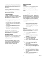
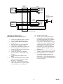
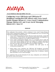
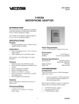
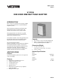
When using the V-1101A with an electronic key
system or PABX, the following equipment will be
required:
24VDC
(1) V-1101A One Zone One-way Page Adapter
(1) C. O. Line Card (electronic key system) or
(1) Loop Trunk Card
Valcom one-way amplified speaker assemblies
(quantity and style determined by specific
installation)
A –24 Vdc power supply (size and quantity
determined by number and style of speakers)
POWER SUPPLY
FIGURE 1 - TYPICAL PABX INSTALLATION
Power Requirements
Voltage:
-21.5 to -26 Vdc
"A" and "B" battery
Current:
"A" Battery, 50 mA*
"B" Battery, 100 mA
* ("A" Battery = filtered talk battery)
Environment
Temperature:
Humidity:
0 to 50 Degrees C
0 to 85% non-precipitating
Operation: Press the appropriate line key (electronic
key system) or dial the appropriate trunk access code
(PABX). You will immediately be connected to the
paging speakers. Make your announcement. The
V-1101A will automatically disconnect when you
hang up.
1A2 Key Button Access
When accessing the V-1101A from a 1A2 key system
line button, the following equipment will be required:
DESIGN
General
The Valcom V-1101A One-Zone One-way Page
Adapter is designed to provide access to paging from
a standard PABX loop trunk port, an electronic key
system or 1A2 key system C. O. line button, or a 1A2
key system intercom number. In some cases, access
is also possible from a PABX or electronic key
system page port.
REMEMBER: All Valcom paging systems are made
up of three basic components: a page control unit,
speakers, and a power supply.
When one-way amplified speaker assemblies are
specified in this manual, consult your Valcom catalog
for the styles available. Once the style and quantity
of speakers is determined, select the appropriate
power supply after referring to the Valcom One-way
Paging manual or the Valcom catalog.
In addition to the parts listed in each of the following
sections, you will need a 66B type punch down block
and a 25-pair cable with a female amphenol
connector. These may be purchased from Valcom as
a unit with the cable and block already connected and
installed on a mounting frame (part # VM-101).
Electronic Key or PABX Access
(1) V-1101A One Zone One-way Page Adapter
Valcom one-way amplified speaker assemblies
(quantity and style determined by specific
installation)
A –24 Vdc power supply if the existing key
system supply is not adequate (the power
requirements are determined by number and
style of speakers)
NOTE: A C.O. line card is NOT required in this
application.
Operation: Press the appropriate line button. You
will immediately be connected to the paging
speakers. Make announcement. The V-1101A will
automatically disconnect when you hang up.
1A2 Intercom Access
When accessing the V-1101A from a bell/ buzzer
intercom connected to a 1A2 key system, the
following equipment will be required:
(1) V-1101A One Zone One-way Page Adapter
(1) Unused intercom number
Valcom one-way amplified speaker assemblies
(quantity and style determined by specific
installation)
A –24 Vdc power supply if the existing key
system supply is not adequate (power
requirements are determined by number and
style of speakers)
NOTE: The intercom used MUST supply a holding
ground or page control lead to properly operate the
2
947101
V-1101A. A page control lead is a lead that supplies
Ground whenever the intercom is in use, and which is
Open when the intercom is idle. Contact the
manufacturer of your intercom if you have questions
about this lead.
Operation: Press the intercom button and dial the
number assigned to the V-1101A. You will then be
connected to the paging speakers. Make
announcement. The V-1101A will automatically
disconnect when you hang up.
Page Port Access
CAUTION: To use the V-1101A on a PABX or
electronic key system page port, the telephone system
MUST SUPPLY both an audio pair AND a dry
contact closure.
When accessing the V-1101A from a page port, the
following equipment will be required:
(1) V-1101A One Zone One-way Page Adapter
Telephone system page card (if page outputs are
not built in)
Valcom one-way amplified speaker assemblies
(quantity and style determined by specific
installation)
A –24 Vdc power supply (size and quantity
determined by number and style of speakers)
Operation: Follow the telephone system
manufacturer's instructions for accessing paging.
Make announcement. The V-1101A will
automatically disconnect when you hang up.
Background Music
Background music may be connected to the V-1101A
when using any of the above configurations. The
background music will automatically cut off when
the paging is accessed.
The background music source should have a output
impedance of approximately 8 Ohms. An output
level of 1 watt will be more than sufficient to drive
the amplified speakers. The background music
source must have it's own volume control.
The wiring of each arrangement is covered in the
next section.
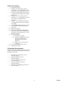
INSTALLATION
General
These instructions cover the installation procedures
for the Valcom V-1101A and any associated
equipment. Please consult practices for other
manufacturer's equipment if any other equipment is
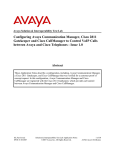
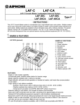
being used. Refer to Figure 2 for connection block
pinouts.
The following sections contain step-by-step
instructions for wiring the Valcom V-1101A one
zone one-way page adapter. Each instruction is
preceded by a line. Place a check on the appropriate
line as the instruction is completed. The instructions
also include tests along the way to verify connections
have been made correctly. If these steps are followed
exactly, installation of your Valcom system will go
smoothly and quickly. If the results of a test do not
correspond with what is shown, DO NOT PROCEED
UNTIL THE PROBLEM HAS BEEN
CORRECTED.
__
NOTE: To facilitate system testing and
balancing, be sure to set the individual
volume controls at approximately 1/2
volume when installing one-way amplified
speaker assemblies.
Mounting
NOTE: DO NOT install the V-1101A or its wiring
closer than 18" to a power supply or any equipment
that generates electrical noise.
__ 1.
__ (a)
__ (b)
__ (c)
__ (d)
__ 2.
__ (a)
__ (b)
__ (c)
__ (d)
3
If you are using the Valcom VM-101
mounting frame:
Using two #6 3/4" wood screws, mount the
frame on a vacant space on the backboard
with the telephone system common
equipment.
Using the bolts supplied, attach the
V-1101A to the mounting frame.
Plug the amphenol ended cable into the
V-1101A.
Attach the V-1101A terminal designation
strip to the punch down block on the frame.
If you are using a separate punch down
block and cable:
Using two #6 3/4" wood screws, mount the
unit in a vacant space on the backboard with
the telephone system common equipment.
Mount a 66 type punch down block near the
unit.
On one column of the block, completely
punch down a 25 pair cable. The other end
of the cable should have a female amphenol
connector.
Plug the amphenol connector into the
V-1101A.__ (e) Mark the punch down
block as shown in Figure 2.
947101
Power Connections
__ 1.
__ 2.
__ 3.
__ 4.
__ 5.
__ 6.
7.
__ (a)
__ (b)
__ (c)
__ (d)
__ 8.
Unplug power supply.
Connect –24 Vdc "B" battery (may be
referred to as "–" or "signal battery") from
power supply to BB (S/V) of the V-1101A.
Connect –24 Vdc Ground ("B" ground, "+",
or "signal" ground) from the power supply
to BG (V/S).
Connect –24 Vdc "A" battery (may be
referred to as "–" or "talk battery") from the
power supply to AB (BR/V) of the
V-1101A.
Connect –24 Vdc Ground ("A" ground, "+",
or "talk ground") from the power supply to
AG (V/BR).
Connect GROUND from the power supply
to a good Earth or Water Pipe ground.
Power Test:
Plug in power supply.
Using a screwdriver, momentarily short
between the BFT (W/S) and BFR (S/W)
leads of the V-1101A and listen for a relay
to operate in the unit.
If no relay is heard:
__ (1) Unplug power supply.
__ (2) Verify the V/BR and V/S pairs are
properly connected at the
punch-down block and in the
amphenol.
__ (3) Return to step 2, and verify all
connections.
If a relay is heard, proceed to step 8.
Unplug power supply.
Connecting Arrangements
NOTE: Place a check by the arrangement being used
and proceed to the Figure indicated for step-by-step
installation instructions.
__ 1.
__ 2.
__ 3.
__ 4.
__ 5.
Electronic key system line key access:
Proceed to Figure 3.
PABX loop trunk port access:
Proceed to Figure 3.
1A2 key system line button access:
Proceed to Figure 4.
1A2 key system intercom access:
Proceed to Figure 5.
Electronic key or PABX page port access:
Proceed to Figure 6.
4
947101
FIGURE 2
A
TIP
RING
HOLDING GROUND
ICM START
GROUND START
NORMALLY OPEN CONTACT
BATTERY FEED TIP
BATTERY FEED RING
NORMALLY OPEN CONTACT
NORMALLY OPEN CONTACT
MUSIC INPUT
PAGE OUT
T
R
H
SIG
DIR
CT2
CT2
BFT
BFR
A1
A1
A2
A2
MT
MR
PG
OUT
-24V START
-24V DIR
FILTERED -24VDC
AG
AB
BG
BB
UNFILTERED -24VDC
B
26
1
27
2
28
3
29
4
30
5
31
6
32
7
33
8
34
9
35
10
36
11
37
12
38
13
39
14
40
15
41
16
42
17
43
18
44
19
45
20
46
21
47
22
48
23
49
24
50
25
C
D
E
F
W/BL
BL/W
W/O
O/W
W/G
G/W
W/BR
BR/W
W/S
S/W
R/BL
BL/R
R/O
O/R
R/G
G/R
R/BR
BR/R
R/S
S/R
BK/BL
BL/BK
BK/O
O/BK
BK/G
G/BK
BK/BR
BR/BK
BK/S
S/BK
Y/BL
BL/Y
Y/O
O/Y
Y/G
G/Y
Y/BR
BR/Y
Y/S
S/Y
V/BL
BL/V
V/O
O/V
V/G
G/V
V/BR
BR/V
V/S
S/V
NOTE: AG AND BG ARE "+", AB AND BB ARE "-"
5
947101
PABX LOOP TRUNK PORT
OR ELECTRONIC KEY
SYSTEM LINE BUTTON
TIP
RING
-24VDC POWER SUPPLY
A GROUND
A BATTERY
B GROUND
B BATTERY
PUNCHDOWN
BLOCK
(W/BL)
(BL/W)
(W/O)
(W/G)
(W/S)
(S/W)
(R/BL)
(BL/R)
26
1
27
28
30
5
31
6
(R/G)
(G/R)
(R/BR)
(BR/R)
33
8
34
9
(V/BR)
(BR/V)
(V/S)
(S/V)
49
24
50
25
V-1101A
T (W/BL)
R (BL/W)
H (W/O)
DIR
(W/G)
BFT (W/S)
BFR (S/W)
A1 (R/BL)
A1 (BL/R)
MT (R/G)
MR (G/R)
ONE-WAY
AMPLIFIED SPEAKER
ASSEMBLIES
PG (R/BR)
OUT (BR/R)
AG
AB
BG
BB
(V/BR)
(BR/V)
(V/S)
(S/V)
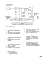
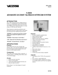
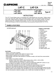
FIGURE 3
ELECTRONIC KEY SYSTEM LINE BUTTON ACCESS OR PABX LOOP TRUNK ACCESS
WIRING INSTRUCTIONS
Place a check by each step as it is completed.
__ 1. Add a strap on the V-1101A punchdown
block from Tip to BFT (W/BL to W/S).
__ 2. Add a strap from Ring to BFR (BL/W to
S/W).
__ 3. Add a strap from H to DIR (W/O to W/G).
__ 4. Add a strap from DIR to Red/Blue (W/G to
R/BL).
__ 5. Add a strap from Blue/Red to BG (BL/R to
V/S).
__ 6. Connect Tip of the one-way amplified
speaker assemblies to the V-1101A PG lead
(R/BR).
__ 7. Connect Ring of the speakers to the OUT
lead (BR/R).
__ 8. Connect the GND terminal of the speakers
(black lead of horns) to the power supply
Ground ("+" or "B Ground").
__ 9. Connect the –24 Vdc lead of the speakers
(white lead of horns) to the power supply
–24 Vdc ("-" or "B Battery").
__ 10. Plug in the power supply.
__ 11. Test the unit by connecting a lineman's test
set across the V-1101A Tip and Ring:
__
(a) Go "off hook" and speak. Your voice
should come out the speakers.
__
(b) If you hear the page: disconnect your
test set and go to step 12.
__
(c) If you do not hear the page:
(1) unplug the power supply;
(2) go back to step 1 and recheck all
your connections.
__ 12.
__ 13.
__ 14.
__
__
__ 15.
__ 16.
__
__
6
Connect the tip (W/BL) of the V-1101A to
Tip of your telephone system loop trunk port
(PABX) or C.O. line position (E-key).
Connect the Ring (BL/W) of the V-1101A
to Ring of the telephone system.
Test the system by dialing the proper trunk
access code (PABX) or pressing the
appropriate line key (E-key) and speaking
into the handset:
(a) If you hear the page, go to step 15.
(b) If you do not hear the page, verify proper
telephone system configuration and
programming. If you have programming
questions, contact the telephone system
manufacturer.
Adjust the volume controls on the individual
speakers to the desired levels.
If background music is to be provided:
(a) Connect the music source to the
V-1101A MT and MR (R/G and G/R).
(b) With the V-1101A idle adjust the music
source volume control to provide the desired
level at the speakers.
947101
1A2 TELEPHONES
PAGE BUTTON
TIP
RING
LAMP
LGND
PUNCHDOWN
BLOCK
(W/BL)
(BL/W)
V-1101A
26
1
T (W/BL)
R (BL/W)
H (W/O)
DIR
(W/G)
BFT (W/S)
BFR (S/W)
A1 (R/BL)
A1 (BL/R)
POWER SUPPLY
LAMP GROUND
LAMP BATTERY
A GROUND
A BATTERY
B GROUND
B BATTERY
(R/O)
(O/R)
32
7
PG (R/BR)
OUT (BR/R)
(V/BR)
(BR/V)
(V/S)
(S/V)
49
24
50
25
A2
A2
MT
MR
(R/O)
(O/R)
(R/G)
(G/R)
AG
AB
BG
BB
(V/BR)
(BR/V)
(V/S)
(S/V)
ONE-WAY
AMPLIFIED SPEAKER
ASSEMBLIES
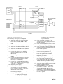
FIGURE 4
1A2 KEY SYSTEM LINE BUTTON ACCESS
WIRING INSTRUCTIONS
Place a check by each step as it is completed.
__ 1. Add a strap on the V-1101A punchdown
block from Tip to BFT (W/BL to W/S).
__ 2. Add a strap from Ring to BFR (BL/W to
S/W).
__ 3. Add a strap from H to DIR (W/O to W/G).
__ 4. Add a strap from DIR to Red/Blue (W/G to
R/BL).
__ 5. Add a strap from Blue/Red to BG (BL/R to
V/S).
__ 6. Connect Tip of the one-way amplified
speaker assemblies to the V-1101A PG
(R/BR) lead.
__ 7. Connect Ring of the speakers to OUT
(BR/R).
__ 8. Connect the GND terminal of the speakers
(black lead of horns) to the power supply
Ground ("+" or "B Ground").
__ 9. Connect the –24 Vdc lead of the speakers
(white lead of horns) to the power supply
–24 Vdc ("–" or "B Battery").
__ 10. Plug in the power supply.
__ 11. Test the unit by connecting a lineman's test
set across the V-1101A Tip and Ring:
__
(a) Go "off hook" and speak. Your voice
should come out the speakers.
__
(b) If you hear the page: disconnect your
test set and go to step 12.
__
(c) If you do not hear the page:
(1) unplug the power supply;
__ 12.
__ 13.
__ 14.
__ 15.
__ 16.
__
__
__
__ 17.
__ 18.
__
__
7
(2) go back to step 1 and recheck
all your connections.
Cross-connect the tip (W/BL) of the
V-1101A to Tip of the paging line button of
all your telephones.
Cross-connect Ring (BL/W) of the V-1101A
to Ring of all the telephone paging buttons.
Cross-connect the Red/Orange (R/O) of the
V-1101A to the lamp lead of the paging line
button on all telephones.
Connect from the V-1101A Orange/Red
(O/R) to the power supply 10 Vac.
Test the system by pressing the page line
button and speaking into the handset:
(a) If you hear the page and see a lamp on
the phones go to step 17.
(b) If you do not get a lamp verify steps 14
and 15 have been performed correctly.
(c) If you do not hear the page verify steps
12 and 13 have been performed correctly
and all connections are good.
Adjust the volume controls on the individual
speakers to the desired levels.
If background music is to be provided:
(a) Connect the music source to the
V-1101A MT and MR (R/G and G/R).
(b) With the V-1101A idle adjust the music
source volume control to provide the desired
level at the speakers.
947101
INTERCOM
TIP
RING
PC
SIG
RET
BLOCK
(W/BL)
(BL/W)
(W/O)
(O/W)
V-1101A
26
1
27
2
T
R
H
SIG
MT
MR
(W/BL)
(BL/W)
(W/O)
(O/W)
(R/G)
(G/R)
AUDIO SIG
AUDIO GND
ONE-WAY
AMPLIFIED SPEAKER
ASSEMBLIES
AUD GND
AUD SIG
A GND
A BATT
B GND
B BATT
PG (R/BR)
OUT(BR/R)
(V/BR)
(BR/V)
(V/S)
(S/V)
49
24
50
25
AG (V/BR)
AB (BR/V)
BG (V/S)
BB (S/V)
POWER SUPPLY
FIGURE 5
1A2 INTERCOM ACCESS
WIRING INSTRUCTIONS:
__ 6.
Place a check by each step as it is completed.
__ 1.
__ 2.
__ 3.
__ 4.
__ 5.
__
__
__
Connect from the V-1101A Tip (W/BL) to
Tip of your intercom.
Connect from the V-1101A Ring (BL/W) to
the intercom Ring.
Connect from the V-1101A H (W/O) to the
intercom page control lead (may be called
Holding Ground).
Connect from the V-1101A SIG (O/W) to
the intercom number being used for page
access. Important Note: The V-1101A
requires only one lead from the intercom
number. On Valcom intercoms this is the
"S" lead. On other intercoms it is usually
the "R" or "Ring" lead.
Connect from the V-1101A BG (V/S) to one
of the following:
(a) Power supply ring ground if using 105
Vac for intercom signaling.
(b) Power supply 18 Vac ground if using 18
Vac for intercom signaling.
(c) Power supply 10 Vac ground if using 10
Vac for intercom signaling.
__ 7.
__ 8.
__ 9.
__ 10.
__ 11.
__
__
__ 12.
__ 13.
__
__
8
Connect Tip of the one-way amplified
speaker assemblies to the V-1101A PG
(R/BR) lead.
Connect Ring of the speakers to OUT
(BR/R).
Connect the GND terminal of the speakers
(black lead of horns) to the power supply
Ground ("+" or "B Ground).
Connect the –24 Vdc lead of the speakers
(white lead of horns) to the power supply
–24 Vdc terminal ("-" or "B Battery").
Plug in the power supply.
Test the system by pressing down the
intercom button, dialing the code for page
access, and speaking into the handset.
(a) If you hear the page go to step 12.
(b) If you do not hear the page unplug the
power supply, go back to step 1, and verify
all your connections. Also repeat the power
test in power connection section, step 7.
While paging, adjust the volume controls on
the individual speakers to the desired levels.
If background music is to be provided:
(a) Connect the music source to the
V-1101A MT and MR (R/G and G/R).
(b) With the V-1101A idle, adjust the music
source volume control to provide the desired
level at the speakers.
947101
PUNCHDOWN
BLOCK
TIP
RING
CONTACT
(W/BL)
(BL/W)
(W/O)
(O/W)
V-1101A
26
1
27
2
T
R
H
DIR
MT
MR
(W/BL)
(BL/W)
(W/O)
(W/G)
(R/G)
(G/R)
ONE-WAY
AMPLIFIED SPEAKER
ASSEMBLIES
PG (R/BR)
OUT(BR/R)
A GROUND
A BATTERY
B GROUND
B BATT
(V/BR)
(BR/V)
(V/S)
(S/V)
49
24
50
25
AG (V/BR)
AB (BR/V)
BG (V/S)
BB (S/V)
FIGURE 6
PAGE PORT ACCESS
WIRING INSTRUCTIONS:
Place a check by each step as it is completed.
__ 1.
__ 2.
__ 3.
__ 4.
__ 5.
__ 6.
__ 7.
__ 8.
__ 9.
Connect the Tip (W/BL) of the V-1101A to
Tip of your telephone system page port.
Connect the Ring (BL/W) lead to Ring of
the page port.
Add a strap on the V-1101A punchdown
block from H to DIR (W/O to W/G).
Connect the V-1101A BG (V/S) lead to one
side of the page port dry contact closure.
Connect the other side of the contacts to the
V-1101A H (W/O) lead.
Connect Tip of the one-way amplified
speaker assemblies to PG (R/BR) of the
V-1101A.
Connect Ring of the speakers to OUT
(BR/R).
Connect the GND terminals of the speakers
(black lead of horns) to the power supply
Ground ("+" or "B Ground").
Connect the –24 Vdc lead of the speakers
(white lead of horns) to the power supply
–24 Vdc terminal ("-" or "B Battery").
__ 10.
__ 11.
__
__
__ 12.
__ 13.
__
__
9
Plug in the power supply.
Test the system by dialing the telephone
system page access code or pressing the
page button and speaking into the handset:
(a) If you hear the page go to step 12.
(b) If you do not hear the page verify steps
1-10 have been performed properly and all
connections are good. Also verify proper
telephone system configuration and
programming. If you have programming
questions contact the telephone system
manufacturer.
Adjust the volume controls on the individual
speakers to the desired levels while paging.
If background music is to be provided:
(a) Connect the music source to the
V-1101A MT and MR (R/G and G/R).
(b) With the V-1101A idle adjust the music
source volume control to provide the desired
level at the speakers.
947101
OPERATION
General
The V-1101A contains the required circuitry to allow
paging access from most types of telephone systems.
To operate correctly, the V-1101A must receive two
signals: a ground on the Holding Ground input and
either a momentary AC signal on the Signal Input
lead or a momentary or continuous ground on the
Ground Start lead.
The unit may be wired for loop start operation for use
on PABX's or electronic key systems (Figure 3). In
this application the unit will supply the –24 Vdc talk
battery required by the telephone system trunk card.
The holding ground and start leads required by the
page unit will be supplied internally in this case.
Connections for access by a 1A2 line button are
similar to those above, except that the unit is
cross-connected directly to the button of the
telephone instead of to a trunk card (Figure 4). A
spare set of relay contacts is used to switch lamp
voltage to the phones.
When connecting the V-1101A to an intercom
number (Figure 5) four leads are required from the
intercom: Tip and Ring to supply audio, a Page
Control Lead, and a Signal Lead. The Page Control
Lead must supply a Ground whenever the intercom is
in use, and must be open when the intercom is idle.
This lead is used to release the V-1101A at the end of
a page. The intercom may be wired to use 10 Vac,
18 Vac, or 105 Vac for signaling. The intercom
signal must be momentary, i.e., the signal must be
present for approximately 1 second and then drop off.
A continuous signal will prevent the V-1101A from
operating.
When connecting the V-1101A to a page port (Figure
6) a Ground must be connected through the dry
contact closure of the telephone system page card to
both the Holding Ground and the Ground Start
terminals of the V-1101A.
Once the V-1101A has been activated it will remove
the background music (if connected) from the
speakers and allow you to page. The unit will stay
active until you hang up, at which time the holding
ground will be removed and the unit will be allowed
to release.
TECHNICAL ASSISTANCE
When trouble is reported, verify the unit is properly
connected and there are no broken connections
leading to this unit.
Assistance in troubleshooting is available from the
factory. When calling, you should have a VOM and
a test set and be calling from the job site. Call (540)
563-2000 and press 1 for Technical Support, or visit
our website at http://www.valcom.com.
Valcom equipment is not field repairable. Valcom,
Inc. maintains service facilities in Roanoke, VA.
Should repairs be necessary, attach a tag to the unit
clearly stating company name, address, phone
number, contact person, and the nature of the
problem.
Send the unit to:
Valcom, Inc.
Repair & Return Dept.
5614 Hollins Road
Roanoke, VA 24019-5056
10
947101
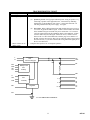
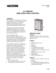
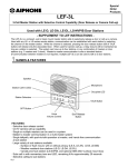
TROUBLESHOOTING CHART
Symptom
Solution
1. No output at speakers.
1.
Check for audio on the Red/Brown pair of the V-1101A while paging.
(a)
If audio is present: Verify proper audio and power wiring to speakers. Try
connecting a speaker in the equipment room: Connect the Tip and Ring
leads directly to the Red/Brown pair of the V-1101A and connect the –24
Vdc and ground leads to the power supply. Test again.
(b)
2. Music will not cut off
during a page.
Preamplifier
and
Voice Limiting Ckt
T
R
BFT
BFR
AB
AG
2.
If no audio: Refer to Wiring Instructions and complete the power test (step
7). Correct any problems and test again. If there is still no audio, then return
to the installation Figure used and verify ALL connections. Use a meter to
verify the connections from the punchdown block to the amphenol. If there
is still no audio and you used Figure 5 Intercom Access, connect a bell or
buzzer to the V-1101A H and SIG leads. Dial the page access number. If
the bell or buzzer does not ring, then you are either not getting a page control
from the intercom, or you have connected the wrong half of the signal pair to
the V-1101A SIG lead.
Complete all steps above for “no output at speakers”.
PG
OUT
MT
Battery Feed
and
A Relay
MR
H
SIG
DIR
BB
Control Circuit
and
A1
A1
A1
A2
A2
A2
CT2
CT
CT
CT Relay
Regulator
BG
V-1101A SIMPLIFIED SCHEMATIC
11
947101
VALCOM LIMITED WARRANTY
Valcom, Inc. warrants its products only to the original purchaser, for its own use, to be free from defects in materials and workmanship under conditions of
normal use and service for a period of one year from the date of shipment. This Limited Warranty obligation shall be limited to the replacement, repair or
refund of any such defective device within the warranty period, provided that:
1. inspection by Valcom, Inc. indicates the validity of the claim;
2. the defect is not the result of damage, misuse or negligence after the original shipment;
3. the product has not been altered in any way or repaired by others and that factory sealed units are unopened (a service charge plus parts
and labor will be applied to units defaced or physically damaged);
4. freight charges for the return of products to Valcom are prepaid;
5. all units 'out of warranty' are subject to a service charge. The service charge will cover minor repairs (major repairs will be subject to
additional charges for parts and labor).
This Limited Warranty is in lieu of and excludes all other warranties, expressed or implied and in no event shall Valcom, Inc. be liable for any
anticipated profits, consequential damages, loss of time or other losses incurred by the buyer in connection with the purchase, operation,
maintenance, installation, removal or use of the product. The maximum liability of Valcom under this warranty is limited to the purchase price of the
specific Product covered by the warranty.
Disclaimer. Except for the Limited Warranty provided herein, the product is provided “as-is” without any warranty of any kind whatsoever including, without
limitation, any WARRANTY OF MERCHANTABILITY, FITNESS FOR A PARTICULAR PURPOSE OR NON-INFRINGEMENT.
This warranty specifically excludes damage incurred in shipment. In the event a product is received in damaged condition, the carrier should be notified
immediately. Claims for such damage should be filed with the carrier involved in accordance with the F.O.B. point.
Headquarters:
Valcom, Inc.
5614 Hollins Road Roanoke, VA 24019-5056
Phone: (540) 563-2000 FAX: (540) 362-9800
12
947101