1
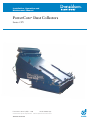
Installation, Operation and
Maintenance Manual
PowerCore Dust Collectors
®
Series CPV
Publication 3012C (GB) • 1108
Donaldson reserve the right to alter design without notice.
'MASTER' LANGUAGE
1A 6519 8000 (03)
Freedom from patent restrictions must not be assumed.
Installation, Operation and Maintenance Manual
PowerCore Dust Collectors – Series CPV
®
IMPORTANT
PLEASE READ THIS MANUAL CAREFULLY BEFORE INSTALLATION.
THIS MANUAL SHOULD BE READ IN CONJUNCTION
WITH THE CONTROLLER MANUAL, PUBLICATION 2699,
SUPPLIED WITH THE DUST COLLECTOR.
PRODUCT RELIABILITY, WARRANTY AND
SAFE OPERATION MAY BE COMPROMISED BY NOT FOLLOWING
THE GUIDANCE GIVEN IN THESE DOCUMENTS.
EXPLANATION OF SYMBOLS USED
Indicates information on the efficient operation of the collector.
Indicates important information directed towards preventing damage.
Indicates an important warning, designed to prevent injury or extensive damage.
2
Installation, Operation and Maintenance Manual
PowerCore Dust Collectors – Series CPV
®
IMPORTANT
Improper operation of a dust control system may contribute to conditions
in the work area or facility that could result in severe personal injury and
product or property damage. Check that all collection equipment is
properly selected, sized and operated for the intended use.
These details correspond to the serial nameplate
located on the right-hand side panel of the equipment
3
Installation, Operation and Maintenance Manual
PowerCore Dust Collectors – Series CPV
®
CONTENTS
General safety requirements .................................................................................. 5
Installation ............................................................................................................... 8
General guidance to lifting ............................................................................. 8
Mounting over aperture .................................................................................. 9
Compressed air requirements ........................................................................ 9
Controller ...................................................................................................... 10
Explosion protection ..................................................................................... 10
Installation check list ..................................................................................... 10
Commissioning ..................................................................................................... 11
Commissioning check list ............................................................................. 11
Start-up sequence ........................................................................................ 11
Shut-down sequence .................................................................................... 12
Operation ............................................................................................................... 13
Principle of operation .................................................................................... 13
Maintenance .......................................................................................................... 14
Routine inspection ........................................................................................ 14
Servicing schedule ....................................................................................... 15
Filter pack replacement ................................................................................ 17
Specification .......................................................................................................... 19
Spare Parts ............................................................................................................ 21
Declaration of Conformity .................................................................................... 23
Table 1
Fault location ....................................................................................... 18
Table 2
Compressed air manifold design details ............................................ 19
Table 3
Compressed air requirements ............................................................ 20
4
Installation, Operation and Maintenance Manual
PowerCore Dust Collectors – Series CPV
®
GENERAL SAFETY REQUIREMENTS
The dust collector should be used only when it is in a technically
acceptable condition. Regular maintenance, as set out in this manual,
is required to minimise technical failure. Third party supplied
components (for example motors) should be maintained according to
the manufacturer's instructions.
You should ensure any persons carrying out work on the supplied
equipment follow any relevant recognised standards/codes and are
competent to do so. Areas requiring a competent person include:
G Maintenance on any component identified as a potential ignition
source.
G Lifting and erection.
G Electrical installation, inspection and maintenance work.
G Pneumatic installation, inspection and maintenance work.
G Any access to internal classified potentially explosive atmospheres
where there may be a risk due to explosion.
During assembly/installation or dismantling of equipment, potential
ignition sources may occur that were not considered in the risk
assessment of the unit in operation (for example, grinding, welding
sparks, etc.)
You should use the dust collector in full accordance with the conditions
set out in the Order Acknowledgment and relevant Scope of Delivery.
Failure to do so may compromise product reliability, warranty and safety.
The Scope of Delivery is an integral part of the manual.
Other items of equipment, not supplied under the Scope of Delivery
from Donaldson, should be installed, operated and maintained
according to the documentation supplied with the respective equipment.
Any modification carried out on the 'as supplied' equipment may reduce
reliability and safety, and will nullify warranty; such actions fall outside
the responsibility of the original supplier.
Where necessary for safety, the dust collector is fitted with fixed guards.
Removal of these guards and any subsequent work should only be
carried out after adequate precaution is taken to ensure it is safe to do
so. All guards should be refitted before re-energising.
5
Installation, Operation and Maintenance Manual
PowerCore Dust Collectors – Series CPV
®
GENERAL SAFETY REQUIREMENTS
Compressed air is recommended for collectors that operate using
reverse jet cleaning. Alternative gases should be assessed before use
to ensure that explosive atmospheres are not introduced during media
cleaning.
Where the equipment supplied is suitable for working within a potentially
explosive atmosphere (as defined by Directive 94/9/EC) it will be
according to the categories and conditions marked on the collector
serial nameplate. You should ensure the equipment supplied by others
is also suitable. If no marking is given on the serial nameplate then the
supplied equipment is not suitable for use in potentially explosive
atmospheres.
Care should be taken to ensure that any potentially explosive
atmosphere is not present when performing operations that increase
the risk of ignition (opening of controller for adjustment or electrical
repair for example). Ensure the installation is always returned to its
original state.
Where the dust being processed can ignite due to exothermic reaction,
including self ignition, the installation MUST be fitted with a suitable
explosion protection method (venting for example). The risk of ignition
can be minimised by avoiding the accumulation of dust layers with
regular cleaning.
Precautions, as set out in the Scope of Delivery, are used to minimise
the risk of ignition of any dust clouds contained within the dust collector.
The possibility of other ignition sources being introduced into the
collector during periods where any dust cloud may be present should
be minimised. Particular care should be taken to avoid introducing
glowing particles via the inlet ducting.
Where applicable, equipment connected to the dust collector (for
example, a cyclone) should be protected, using suitable isolation
devices, against the transfer of flame and pressure if, in the event of an
explosion initiating inside the dust collector, the connected equipment
is not capable of safely withstanding these effects.
It may be necessary to provide a facility to shut down the equipment in
the event of an explosion.
6
Installation, Operation and Maintenance Manual
PowerCore Dust Collectors – Series CPV
®
Compressed air
distribution manifold
Compressed
air inlet
Hinged
access door
Diaphragm
valves
Filter packs
Lifting
eyebolts
Cleaned air outlet
Mounting flange
Figure 1 PowerCore dust collector
Model CPV-3 illustrated
7
Installation, Operation and Maintenance Manual
PowerCore Dust Collectors – Series CPV
®
INSTALLATION
Where equipment is installed in a Potentially Explosive Atmosphere,
care should be taken not to locate or use the collector where external
ignition sources can be introduced, for example stray electric currents,
lightening, electromagnetic waves, ionising radiation, ultrasonic waves.
General guidance to lifting
Refer also to Figure 2
The collector should be lifted using the lifting eyebolts provided.
During all lifting operations a crane or fork lift with an adequate SWL
(safe working load) must be used. (Refer to lifting label located adjacent
to lifting eyebolts for weight of equipment supplied by Donaldson).
Slings with an adequate SWL (safe working load) must be used. (Refer
to lifting label located adjacent to lifting eyebolts for weight of equipment
supplied by Donaldson).
Use clevis connectors, not hooks, on lifting slings.
Use spreader bar to prevent damage to collector casing.
Take centre of gravity into consideration when lifting collector.
30°°
Angle not to exceed
30° from vertical
Figure 2
Four-point lifting arrangement (CPV-4 illustrated)
8
Do not lift
with this orientation
Installation, Operation and Maintenance Manual
PowerCore Dust Collectors – Series CPV
®
INSTALLATION
Mounting over aperture
1 Check that the aperture and fixing holes are correct in size and position to
suit the mounting-flanges of the PowerCore dust collector (details of aperture
and mounting flange fixing positions are provided in Publication 3010).
2 Open the access door and remove the pack of
sealing strip from the clean air chamber.
Apply two continuous beads of sealing strip all round
aperture, on either side of the fixing holes, as shown.
3 Following the general guidance to lifting, lift and position the collector until
the mounting-flange is seated in position over the aperture. Match up fixingholes, install bolts, washers and nuts and tighten down all round to form an
airtight seal.
Fixing bolts etc. are not supplied by Donaldson.
Compressed air requirements
PowerCore dust collectors require an independent supply of clean, dry, oil-free
compressed air. Details of atmospheric pressure and quantity are given in
Table 3 (refer to ‘Specification’ section). A design label is also attached to each
manifold. Where an existing factory mains system is to be used it may be
necessary to install an additional moisture separator in the supply line to the
collector. If a compressor is being installed to supply the collector, then the
following conditions should be observed as far as possible:
Type of compressor
Use a compressor of ample capacity – an overloaded compressor tends to
produce excessively contaminated, moisture-laden air.
Location of air intake
Avoid locating the air intake in an excessively polluted area and install an adequate
air intake filter. The compressor air intake should be sited, if possible, on the
north side of the building – fresh air drawn from the north side is usually cooler
and denser, and therefore has a lower moisture content. (South of the equator
the reverse will apply).
Layout and installation of air lines
The pipework between compressor and dust collector should be long enough to
act as a cooling device for the compressed air. A typical requirement for the
smaller installation would be 10m (30ft) of 12mm (½" NB) piping. For further
details see Table 3. The piping should be installed to provide a fall in the direction
of air flow to assist in the drainage of accumulated moisture. A moisture separator
should be provided at the lowest point of the installation.
9
Installation, Operation and Maintenance Manual
PowerCore Dust Collectors – Series CPV
®
INSTALLATION
Pressure relief
The manifold has a maximum operating pressure of 6.2 bar (see Table 2 in
‘Specifications’ section). It is a requirement that adequate precaution is taken to
avoid exceeding this pressure. Where a relief valve is supplied by Donaldson
this device has a relief rating of 25 dm3/s at 7.1 bar. Extra system relief will be
required if the connected supply can exceed this.
Controller
It is a requirement of the Supply of Machinery (Safety) Regulations
1992 to provide adequate isolation and emergency stop facilities. Due
to the varied nature of site installations this cannot be provided by
Donaldson but instead is the responsibility of the customer.
Always isolate power before opening the controller.
Each CPV dust collector is supplied with an IPC (∆Ρ) Controller to operate the
compressed air cleaning system.
CPV-2: 2-way controller
CPV-3: 3-way controller
CPV-4: 4-way controller
CPV-6: 6-way controller
CPV-8: 8-way controller
CPV-12: 12-way controller
For IPC (∆Ρ) Controller connections and set-up, refer to Publication
2699.
Explosion protection
When PowerCore dust collectors are supplied for use where there is a
risk of explosion within the process, any protection fitted to the process
should not generate pressure exceeding the strength rating of the
collector. For CPV-2, CPV-3, CPV-6 and CPV-12 collectors the strength
rating is 0.23 bar; for CPV-4 and CPV-8 collectors the strength rating is
0.26 bar.
Installation check list Ensure the dust collector is securely bolted over the aperture.
Ensure compressed air supply is installed correctly and free from leaks.
Ensure electrical supply is installed correctly and complies to local legislation.
10
Installation, Operation and Maintenance Manual
PowerCore Dust Collectors – Series CPV
®
COMMISSIONING
It is a requirement of the Supply of Machinery (Safety) Regulations
1992 to provide adequate isolation and emergency stop facilities. Due
to the varied nature of site installations this cannot be provided by
Donaldson but instead is the responsibility of the customer.
Commissioning check list Ensure the dust collector is securely bolted over the aperture.
Open the access door(s) and ensure the seal is intact, then close and secure
the door(s).
Ensure controller is connected to the correct voltage and that the pulse
interval and duration settings are correct. For 24V DC ensure polarity is
correct. It is essential that the controller is earthed for both AC and DC
connections.
Ensure electric power is available.
Ensure the compressed air manifold has sufficient protection for overpressure.
Start the compressor and check that the air supply is maintained at the
recommended pressure.
Switch on the controller and check that all valves operate in sequence (look
and listen for exhaust pulses). As each valve operates, the air pressure
reading should drop to approximately 50% of the initial setting and then
return to the initial value.
If any of the above check boxes are not ticked, then the reasons why should be
investigated. (Refer to fault location table in ‘Maintenance’ section).
Start-up sequence
Having completed all the necessary checks, the equipment may be put into
operation. A typical installation should be started up as follows:
1 Start up compressed air supply.
2 Set the equipment being served, if applicable, in motion.
3 Switch on controller.
11
Installation, Operation and Maintenance Manual
PowerCore Dust Collectors – Series CPV
®
COMMISSIONING
Shut-down sequence
At the end of any period of operation it is most important that all residual
deposits are cleared from the PowerCore filter packs. To achieve this,
equipment should be shut down in the following order:
1 Stop the main fan, any blower or pneumatic conveying system, leaving the
controller and compressed air supply switched on to allow the collector to
be cleaned ‘off-line’.
To enable off-line cleaning, refer to controller manual.
2 After 10-15 minutes, switch off the controller and compressor but leave the
discharge equipment running to ensure that it is emptied.
3 After a further 5 minutes, switch off the discharge equipment if applicable.
Adherence to the above procedure will ensure that a PowerCore dust collector
installation is maintained at optimum efficiency.
12
Installation, Operation and Maintenance Manual
PowerCore Dust Collectors – Series CPV
®
OPERATION
Principle of operation
Filtering operation (Fig. 3a)
With the collector mounted on the silo or storage container, dust-laden air enters
the collector through the aperture at the bottom of the collector. Airflow is directed
upwards through the PowerCore filter packs, removing the fine particulate (heavier
particulate falls back into the process). The clean, filtered air passes through the
collector and is discharged through the cleaned air outlet.
Cleaning operation (Fig. 3b)
At regular intervals, governed by the controller, each PowerCore filter pack receives
a short burst of compressed air from an adjacent air diaphragm valve. This
causes a brief, powerful reversal of airflow through the PowerCore filter pack,
effectively dislodging the dust layer which then falls back into the process.
a
Filtering operation (continuous)
b Cleaning operation (intermittent)
Figure 3 Principle of operation
13
Installation, Operation and Maintenance Manual
PowerCore Dust Collectors – Series CPV
®
MAINTENANCE
A platform should be used when carrying out maintenance where the
position of the technician’s feet is greater or equal to 2 metres above
ground level.
Before any work is carried out, ensure the equipment is adequately
isolated and safe.
Ensure the pneumatic system is fully isolated and depressurised before
any work is carried out.
For ancillary equipment not manufactured by Donaldson, refer to
manufacturer's instructions.
If it is unavoidable to work on the equipment while an explosive
atmosphere is present, care should be taken to avoid introducing
ignition sources not present during expected operation. Non-sparking
tools should be used.
Access to the dirty air chamber of the equipment may create risks and
hazards that under normal circumstances are not present and as such
this work must be carried out by competent personnel. These risks
include inhalation of dust and potential explosion hazards.
In order to maintain the original collector specification and to ensure
the same level of safety, only genuine spare parts should be fitted.
Every care has been taken to avoid the risk of ignition of a flammable
atmosphere. The measures taken to avoid ignition should not be altered
since this may result in unsafe operation. Particular care should be
taken during maintenance and component replacement to ensure the
same level of safety is maintained. When replacing fan impellers, avoid
any rubbing of components (to prevent mechanical sparks).
Care should be taken during cleaning and maintenance to avoid
creating static discharges that have the potential to ignite a flammable
atmosphere.
Routine inspection
To maintain the optimum performance of any dust collector, a routine inspection
should be made to minimise down-time in the event of equipment malfunction,
particularly on continuous performance applications and to ensure the equipment
is maintained to its original supply condition.
Any abnormal change in pressure differential across the filter packs indicates a
change in operating conditions and a fault to be rectified. For example, a
prolonged stoppage of compressed air will cause an excessive build-up of dust
on the filter packs, resulting in a greatly increased pressure drop.
14
Installation, Operation and Maintenance Manual
PowerCore Dust Collectors – Series CPV
®
MAINTENANCE
After the fault has been rectified, resumption of compressed air cleaning will
usually return the filter packs to normal efficiency. However, it is advisable to
operate the controller in still-air conditions for a short period to dislodge any
accumulated dust before putting the collector into operation.
Filter pack resistance can be checked by connecting a U-tube manometer or
differential-type pressure gauge to tapping points on the collector body. This will
give a continuous indication of the state of the filter packs. Once running, the
operating resistance will be relatively stable, the actual value depending on the
air volume and the characteristics of the dust being handled.
It is recommended to periodically inspect the general casing integrity.
Do not operate above recommended compressed air pressure.
Excessive pressure will reduce the working life of components.
Servicing schedule
A record of all pressure checks should be kept in a log book to aid the speedy
diagnosis of faulty operation.
Weekly
1 Open the valve at the bottom of the moisture separator bowl and allow the
collected water to drain off, then close the valve.
2 Connect a manometer to tapping points (refer to Routine inspection) and
measure the pressure drop across the filter packs.
Monthly
Check operation of solenoid and diaphragm valves.
It may be necessary to check the operation of the valves while the
system is pressurised. Care should be taken to avoid injury.
If it is found necessary to replace a diaphragm, use the following procedure (see
Fig. 4):
Use service kit available from Donaldson.
1 Remove 6 mm diameter nylon tube (A) by pulling out from valve.
2 Remove the hexagon head set screws and shakeproof washers securing
the valve bonnet (B).
3 The diaphragm and spring (if fitted) can now be replaced, first ensuring the
‘bleed’ hole pin is not blocked.
4 Ensure that diaphragm fits over ‘bleed’ hole pin and that the nylon sealing
washer is inside throat of valve.
5 Position spring (if fitted) inside bonnet recess.
6 Refit bonnet ensuring spring (if fitted) locates over diaphragm disc shoulder
and bonnet locates over ‘bleed’ hole pin.
15
Installation, Operation and Maintenance Manual
PowerCore Dust Collectors – Series CPV
®
MAINTENANCE
7 Refit and tighten the hexagonal head set screws and shakeproof washers.
8 Push-fit 6 mm diameter nylon tube back into valve.
Annually
1 Moisture separator – Isolate the compressed air supply; remove and clean
the filter element.
2 Air manifold – Having isolated the compressed air supply, remove the drain
plug and air inlet connections and clean out any accumulated sludge and
inspect to any current local legislation.
It may be necessary to remove a diaphragm valve for internal
inspection purposes.
3 Doors – Check the dust seals on all access doors for damage or ageing
and ensure that they are properly seated to prevent entry of water. This is
particularly important where the collector is located outside or in a wet
atmosphere.
Faulty seals must be replaced.
4 Antistatic earthing (if fitted) – Check collector earthing continuity.
5 Explosion risks – Check measures taken to avoid ignition sources are still
in place.
A
Diaphragm valve
B
Manifold
Figure 4 Valve diaphragm replacement
16
Installation, Operation and Maintenance Manual
PowerCore Dust Collectors – Series CPV
®
MAINTENANCE
Filter pack replacement
Use safety and protective equipment when removing contaminants and
filter packs.
Dirty filter packs may be heavier than they appear.
Use care when removing filter packs to avoid personal injury.
Do not drop filter packs.
Refer also to Figure 5.
1 Turn off and isolate any air movement equipment associated with the process
(e.g. fan) and check clean air chamber is at atmospheric pressure.
2 Turn off controller and/or compressed air supply.
3 Open access door by releasing fasteners. Swing door fully open and engage
door locking mechanism.
4 Release filter pack retainer wing nuts and remove filter pack retainers.
5 Remove each filter pack by lifting straight up.
6 Insert new filter packs into place.
7 Install filter pack retainers and tighten wing nuts so that each filter pack
gasket is seated firmly.
8 Disengage access door locking mechanism, then close and fasten access
door.
Figure 5
Filter pack replacement (CPV-4 illustrated)
17
Installation, Operation and Maintenance Manual
PowerCore Dust Collectors – Series CPV
®
MAINTENANCE
TABLE 1 – FAULT LOCATION
Symptom
1
Possible cause
Excessive pressure
differential.
Action
1.1 Compressed air
malfunction.
a
If compressor stopped, rectify compressor fault;
check interlocks; check motor and supply;
check drive.
b
If compressor OK, check pulses at manifold
pressure gauge.
c
Clean filters, dismantle and clean moisture
separator.
d Check for excessive water or oil in compressed
air supply, and possible accumulation in
manifold.
1.2 No pulses of air to
valves.
a
Refer to 'Fault location' table in controller manual
supplied with dust collector.
1.3 Filter packs blocked.
a
Run filter packs clear*, then remove each filter
pack in turn and renew any that are damaged.
2
Insufficient airflow.
2.1 Filter packs blocked.
a
Run filter packs clear*, then remove each filter
pack in turn and renew any that are damaged.
3
Visible effluent in
clean air outlet.
3.1 Filter packs not properly
sealed.
a
Ensure filter pack retainers are fitted securely.
3.2 Damaged filter pack.
a
Damaged filter packs can be identified by the
dust present in clean air chamber. Withdraw
filter pack and renew.
*To run filter packs clear, allow the controller to perform several complete
cleaning cycles before switching off compressor etc.
18
Installation, Operation and Maintenance Manual
PowerCore Dust Collectors – Series CPV
®
SPECIFICATION
For other specifications on this product refer to Publication 3010.
For controller specifications refer to Publication 2699.
TABLE 2 – COMPRESSED AIR MANIFOLD DESIGN DETAILS
Design pressure:
Maximum operating
pressure, PS:
Test pressure:
Design temperature:
Maximum rating of
pressure relief device:
Manifold volume:
Product of pressure
and capacity:
Material used for
manifold construction:
Minimum metal
thickness before
manifold requires
special inspection:
6.9 bar (100 psig)
6.2 bar (90 psig)
10.35 bar (150 psig)
−30° to +150°C
25 dm³/s at 7.1 bar (factory set at 7.1 bar) (not supplied as standard)
7 litres (CPV-2)
12 litres (CPV-3 and CPV-6)
17 litres (CPV-4 and CPV-8)
27 litres (CPV-12)
43.4 bar litres (CPV-2)
74.4 bar litres (CPV-3 and CPV-6)
105.4 bar litres (CPV-4 and CPV-8)
167.4 bar litres (CPV-12)
Structural hollow section
To improve corrosion resistance the manifold is painted externally and
internally using cathodic electrocoat.
5.5 mm
1 bar = 105 Pa
19
Installation, Operation and Maintenance Manual
PowerCore Dust Collectors – Series CPV
®
SPECIFICATION
TABLE 3 – COMPRESSED AIR REQUIREMENTS
Collector type
CPV-2
CPV-3
CPV-4
CPV-6
CPV-8
CPV-12
6.2 bar
6.2 bar
6.2 bar
6.2 bar
6.2 bar
6.2 bar
a
c
Atmospheric air
volume – F.A.D. at
12 sec. intervals b
Working compressed
air pressure a
Normal operating pressure.
90 psig
90 psig
90 psig
90 psig
90 psig
90 psig
b
10 m³/h*
16 m³/h
20 m³/h*
16 m³/h
25 m³/h*
25 m³/h
5.9 cfm*
9.4 cfm
11.8 cfm*
9.4 cfm
14.7 cfm*
14.7 cfm
Pulse
duration
Minimum
pipe
diameter c
100 ms
100 ms
100 ms
100 ms
100 ms
100 ms
½" NB (12)
½" NB (12)
½" NB (12)
½" NB (12)
½" NB (12)
½" NB (12)
Recommended initial setting; this may be varied with experience.
Sizes suitable for runs of pipe up to 30 m (100ft) in length. For longer runs consult with Donaldson.
*Estimated data.
1 bar = 105 Pa
20
Installation, Operation and Maintenance Manual
PowerCore Dust Collectors – Series CPV
®
SPARE PARTS
2
1
4
5
3
6
7
CPV-4 illustrated
Figure 6
Spare parts identification
21
9
Installation, Operation and Maintenance Manual
PowerCore Dust Collectors – Series CPV
®
Item
Description
Part number
/
P032422
Filter pack assembly
1
Filter pack, Ultra-Web
2
Filter pack retainer
AD 382 6701
Access door assembly
3
Access door
CPV-2
CPV-3
CPV-4
CPV-6
CPV-8
CPV-12
AD 383 6206
AD 383 2103
AD 381 3903
AD 383 6801
AD 383 5204
AD 382 6805
4
Door seal
5
Door fastener
6
Eyebolt, door fastener
282 4500
7
Door hinge
759 6101
334 1209
AD 382 9701
Controller
8
For controller spares information refer to Publication 2699 – item not illustrated
Compressed air assembly
9
Diaphragm valve
1A 3189 9011
10
Diaphragm valve service kit – item not illustrated
1A 2565 3204
11
Gasket, diaphragm valve – item not illustrated
1A 3189 0049
/ Recommended spares for up to two years' operation
Damaged safety related parts and safety components should be replaced only with
genuine original spare parts otherwise CE mark will become invalid
22
Installation, Operation and Maintenance Manual
PowerCore Dust Collectors – Series CPV
®
DECLARATION OF CONFORMITY
GB
EC DECLARATION OF CONFORMITY
(Machinery directives 98/37/EEC)
Head Office: Donaldson Europe B.V.B.A.
Interleuvenlaan 1, B-3001 Leuven (Heverlee), Belgium
Manufacturing Centres: Donaldson Filtration (GB) Ltd.
Humberstone Lane, Thurmaston, Leicester LE4 8HP, England
Donaldson Industrial CR – koncern s.r.o.
Kralovsky vrch 1986, 432 01 Kadan, Czech Republic
Customer Service Centre: Donaldson Europe B.V.B.A.
Pathoekeweg 166, B-8000 Brugge, Belgium
Description of the machinery: Dust Collector
Brand: Donaldson Torit DCE
Description: See attached Scope of Delivery
The undersigned, authorized by Donaldson, certifies that the machine described above, provided
that it is installed, maintained and used in accordance with the instructions for use and the codes of
practice, meets the essential safety and health requirements of the following Directives:
G
G
G
G
G
Machinery directives 98/37/EEC
Low voltage directive 2006/95/EC
Pressure equipment directive 97/23/EC
Electromagnetic compatibility directive 89/336/EEC
Equipment and protective systems intended for use in
Potentially Explosive Atmospheres 94/9/EC
IMPORTANT! Read the Installation, Operation and Maintenance Manual before using this machine.
If you require additional copies contact your local Donaldson representative.
The machinery must not be put into service until the machinery into which it is to be incorporated
has been declared in conformity with the provisions of the above mentioned directives.
Signature:
Name:
Position:
Heiner Carstensen
Product Development Director
Date: March 2007
23
Installation, Operation and Maintenance Manual
PowerCore Dust Collectors – Series CPV
®
CONTACT DETAILS
BE
GB
FR
Research Park Zone 1
Interleuvenlaan 1
B-3001 Leuven (Heverlee)
Belgium
Tel +32 (0)16 383 970
Fax +32 (0)16 383 938
Email: [email protected]
IT
Via Cesare Pavese, 5/7
I-20090 Opera (Milano)
Italia
Tel +39 025 300 521
Fax +39 025 760 5862
Email: [email protected]
ES
Gran Vía Carlos III No 93-1o
08028 Barcelona
España
Tel +34 933 394 266
Fax +34 933 395 340
Email: [email protected]
DK
Ådalsvej 50
DK 2970 Hørsholm
Danmark
Tel +45 45 57 00 77
Fax +45 45 57 00 44
Email: [email protected]
SE
Ådalsvej 50
Box 32
DK 2970 Hörsholm
146 21 Tullinge
Danmark
Sverige
Tele +45 45 57 00 77
Tele +46 (0)8 778 83 60
Fax +45 45 57 00 44
Fax +46 (0)8 778 68 30
Email: [email protected]
Humberstone Lane
Thurmaston
Leicester LE4 8HP
England
Tel +44 (0)116 269 6161
Fax +44 (0)116 269 3028
Email: [email protected]
33 rue des Vanesses
ZAC PARIS NORD II
BP 50292 Villepinte
95958 Roissy Charles de Gaulle Cedex
France
Tel +33 (0)1 49 38 99 30
Telecopieur +33 (0)1 49 38 99 40
Email: [email protected]
DE
Industriestraße 11
D-48249 Dülmen
Deutschland
Tel +49 (0)25 94 78 141
Fax +49 (0)25 94 78 189
Email: [email protected]
NL
Transistorstraat 44-III
NL-1322 CG Almere
Postbus 60342
NL-1320 AJ Almere
Nederland
Tel +31 (0)36 548 0840
Fax +31 (0)36 548 0850
Email: [email protected]
www.donaldson.com
24