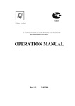
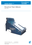
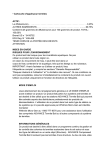
1
Ing. Z. Královský Ing. Petr Štol
Petr 457
675 22 STA
Development&production of control equipment
Visualization, measurement and regulation SW
[email protected]
Tel.:
Fax:
Okrajová 1356
674 01 T EBÍ
+420 568 870982 Tel.: +420 568 421453
+ 420 568 870982 Cell:
+420 777753753
e-mail: [email protected] e-mail: [email protected]
AP Manager
User Manual
September 2014
Version V 1.32
1
1.1
1.2
2
2.1
2.2
3
3.1
3.2
AP Manager Program Installation .....................................................................2
Installing Firebird Server ...................................................................................2
Installing AP Manager proper............................................................................6
Establishing Connection ...................................................................................9
Connecting the Unit ..........................................................................................9
Disconnecting the Unit ....................................................................................11
Units Database..................................................................................................12
Adding a New Unit to the Installation Database ..............................................13
Editing a Unit in Installation Database ............................................................13
4
Basic Panel of the Unit.....................................................................................15
5
Other Functions of the Unit and its Equipment .............................................16
5.1
5.2
5.3
5.4
5.5
5.6
5.7
5.8
5.9
5.10
5.11
5.12
5.13
5.14
5.15
5.16
5.17
Monitor ............................................................................................................17
Parameters .....................................................................................................19
Charts .............................................................................................................20
Tables .............................................................................................................22
Mapping and Function ....................................................................................23
Calibration .......................................................................................................24
Time and Timers .............................................................................................25
History.............................................................................................................26
Deleting history ...............................................................................................26
Service ............................................................................................................26
Counters .........................................................................................................26
Setting SMS (text messages)..........................................................................26
Virtual concentrator .........................................................................................26
User Screen Configuration..............................................................................27
Updating the firmware .....................................................................................28
Mains protection settings protocol...................................................................28
Configuration Backup......................................................................................28
1
AP Manager User Manual
1
AP Manager Program Installation
1.1 Installing Firebird Server
For its operation AP Manager Program requires a local Firebird database server. If it
is not installed on your computer, you must run the Firebird installation first.
http://www.unima-ks.cz/download/2/139/Firebird-2.1_32.exe (32-bit version)
http://www.unima-ks.cz/download/2/140/Firebird-2.1_64.exe (64-bit version)
When the program starts,
select the language to use
during Setup and click OK
to continue
Welcome to Setup. It is
recommended that you
close all other running
applications before
continuing.
Click Next to start the
Setup.
License agreement.
Click "I accept the
Agreement" to confirm the
terms of the license
agreement and click Next to
continue with Setup.
2
AP Manager User Manual
Location of Firebird server
in the Start menu. Click
Next to continue with Setup.
Location of Firebird server
folder. Click Next to
continue.
Information on the Firebird
database server. Click Next
to continue.
3
AP Manager User Manual
Selecting Firebird server
components. Click Next to
continue with Setup.
Additional features of
Firebird server. Click Next
to continue.
.
Setup is now ready to begin
installing Firebird server on
your computer. Click Install
to continue with the
installation.
4
AP Manager User Manual
The progress chart
indicates the progress of
the installation.
Additional information about
Firebird server. Click Next
to continue with the
installation
The installation is complete.
Click Finish to restart your
computer. Firebird server is
now ready.
5
AP Manager User Manual
1.2 Installing AP Manager proper
After installing Firebird server it is now possible to install AP Manager on your
computer.
It is recommended that you
close all running applications
before continuing. Click Next
to run the installation.
... Information about the
program. Click Next to
continue.
Selecting the destination
location where the program
will be installed. The default
folder is
C: \ Program Files \ UNIMAKS \ ManagerAP
Click Next to continue with the
installation.
6
AP Manager User Manual
Selecting program folder. Click
Next to continue with the
installation.
Summary of installation data.
Click Next to continue with the
installation.
After copying the files
complete the installation by
clicking Finish.
Is not necessary to restart the
computer.
Launch the installed program
from the destination folder
using ManagerAP.exe.
7
AP Manager User Manual
1.3 License SW
The program can be freely used only for monitoring and visualization. Other features
of the program (configuration, parameterization, PLC) subject to logging (after
logging occurs or activate other menu items).
Credentials are tied to a specific PC, it can be generated based on the six-digit code
in the header of the main window of ManagerAP.
8
AP Manager User Manual
2
Establishing Connection
2.1 Connecting the Unit
After launching AP Manager a drop-down tree will appear in the left part of the
window, from which you can select the connection method.
To connect to a device that is already defined in the database, select from
"Database Setup" in the tree region (group) of units and then the location of
installation. If there are multiple units in installation all of them can be connected at
the same time. After clicking on the tree it is also possible to select one unit only. The
Program communicates only with devices at defined addresses that are defined
under the appropriate unit (the Program does not search for devices). In the case of
COM the Program uses COM for the connected units defined in the menu "Settings /
Basic Settings ...".
It is possible to connect to an unknown or new unit (the unit is not defined in the
database, we do not know the type or device address) via the "Connect". After
clicking on "Connection" select the connection type (COM, TCP) and the number of
COM or IP address. After connecting the Program immediately displays all the
devices at all addresses available on the particular plug (this concerns all the devices
interconnected via RS-485. It doesn´t matter what devices your PC is connected to
via RS-232 or Ethernet).
Use left mouse button to mark the unit from the database (number of COM or IP
address of the connection) to which you want to connect.
After pressing the right mouse button on the selected unit a menu appears, from
which you select connection type (in the case of unit selection from the database):
Public IP address - remote connection to the unit via the Internet.
IP address of the local network - local connection to the unit via the internal
network.
COM - local connection to the unit via the RS-232 serial line.
9
AP Manager User Manual
10
AP Manager User Manual
2.2 Disconnecting the Unit
If you select the connected unit with the left mouse button, pressing the right
mouse button opens a menu to disconnect the unit. After disconnecting the unit, the
plug icon will turn grey.
If you select the whole region with the left mouse button, pressing the right
mouse button opens a menu to disconnect all the units in the given region.
11
AP Manager User Manual
3
Units Database
The units can be stored in the installation database. With the units defined in
the installation database the user can define (customize) the monitor window, and
create groups of variables in the chart, etc. for each unit separately. Information
about the unit (for example, the last known configuration displayed while off-line) is
saved in a special directory defined by the name of the unit. Directory name syntax is
as follows:
... \ UNIMA-KS \ ManagerAP \ Sites \ Region_Místo
Or
... \ UNIMA-KS \ ManagerAP \ Sites \ Region_Místo_1
... \ UNIMA-KS \ ManagerAP \ Sites \ Region_Místo_2
if there are multiple units in the given installation.
Region means a group of units (eg, country):
AAA ... Australia and Oceania
BLG … Belgium
CZE … Czech Republic
GEN ... Germany
HUN ...Hungary
LAT ... Latvia
POL ...Poland
SLV ... Slovakia
etc.
If needed, region may also mean a region of a country, customer or unit type.
By copying an entire directory of the given unit from one PC to another it is
possible to copy a unit from the database to another PC. The unit database tree is
created only when you start the program, so it is appropriate to copy the directories
when the program is not running.
12
AP Manager User Manual
3.1 Adding a New Unit to the Installation Database
If you connect to an "unknown" unit via the menu "Connect", you can save this
unit in the installation database .By clicking on the plug through which you are
connected, a list of addresses and devices will be displayed which the Program found
at these particular addresses.
If you select with the left mouse button the address of a unit you want to add to
the database (eg, [A0] is the unit at the address 0), by pressing the right button a
menu will appear to add units to the database:
The Program will add to the form the control system found and other additional
equipment. After adding other available data (unit name, IP address, etc.) and
pressing OK, the unit will be stored in the database. It is important to fill in the
"Region" and "Installation Location", these data cannot be edited later and they
specify the directory in which all subsequent unit data will be stored (see Directory
Syntax in the previous section).
On the right side you can insert an image of the installation and other text notes to
installation.
3.2 Editing a Unit in Installation Database
In the menu for connecting a unit from the installation database there is also
an option for setting the unit. The unit can be edited only if it is not connected (offline).After selecting the unit settings in the menu the same form will be displayed as
in the case of adding a new unit to the database. You can modify or supplement the
information about a unit at any time (with the exception of "Region" and "Installation
Location").
As mentioned above, newly attached additional devices are not detected in the
units that are defined in the database. For example, when an external module is
attached to the unit only after the unit has been added to the database (or the
Program failed to detect the module when the unit was added to the database), you
must define the module in the settings manually.
Additional equipment such as UIS ignition, USC speed controller, UVR voltage
regulator always have the "Slot" set to "0". The extension modules must always have
13
AP Manager User Manual
the "Slot" set to a different value (1 to 7 for analog inputs, 8 ÷ 15 for analog outputs,
and 1 ÷ 15 for binary modules). For these modules the "Slot" address must be set
using a PC and RS-232 before their interconnection via RS-485).
14
AP Manager User Manual
4
Basic Panel of the Unit
After a successful connection, the "plug" of the unit in the database will turn green
and the basic unit control panel will appear on the right side of the screen.
If the plug turns red, you cannot establish a connection (the plug is busy or
unavailable).At one time you can connect to any number of units. If there are multiple
units in a given installation you can connect to all the units on the installation with a
single click. By clicking on the installation tree you can select only one unit.
On the basic panel you will find information about the current and the desired
performance of the unit. A segment indicator indicates the desired performance. If a
lower red value also flashes on the segment indicator this means that the
performance of the unit is restricted for some reasons (high water temperature, high
mixture temperature mixtures, etc.).The red value on the segment indicator indicates
the limited level of performance on which the unit performs control.
The analog display ("clock") has three indicator pointers. The red pointer is the actual
performance of the unit, the green one is the required performance and the gray
pointer is the level of performance on which the unit controls. If the pointers overlap
(see figure) the unit functions at the required performance without any restriction.
The basic panel also contains the following controls:
Start of the unit in manual or semi-automatic mode
Shutdown of the unit
Acknowledgment of error
Setting the desired performance
Displaying the charts (of the control system)
Displaying details of the unit (of the control system)
Viewing and editing parameters (of the control system)
Viewing history
Unit mode (off, manual, semiautomatic, automatic)
Power mode (M=manual, E=external request)
15
AP Manager User Manual
5
Other Functions of the Unit and its Equipment
A unit means a machine (such as a cogeneration unit) as a whole. The unit may
consist of multiple devices (control system, ignition, speed controller, voltage
regulator, binary expansion modules, analog expansion modules, etc.).By clicking on
the unit tree you will display all devices the unit contains (regardless of the device
through which you are physically connected to the unit).If you click on the device with
the left mouse button, clicking on the right button will call up a menu with additional
functions for each selected device (some functions are only visible in certain devices
and after user login and password).
16
AP Manager User Manual
5.1 Monitor
Click on the "magnifying glass" in the basic unit panel (or selecting "Monitor" in
the menu of the device) to see more details of the unit.
This window can be customized in the installation (if the user is logged with the
right to configure the monitor, and if you are connected to the unit from the
installation database). By right-clicking on the free space of the window a menu will
pop up to add an object to the monitor:
Load bitmap background (loading an image bitmap into the background)
Add LED indicator (adding binary variable indicator)
Add Segment indicator (adding analog variable indicator)
Add Pump (adding a pump symbol controlled by a binary variable)
Add Three-way valve (adding a three-way valve symbol controlled by two
binary variables)
Save the screen settings (saving the screen configuration to the appropriate
installation folder
17
AP Manager User Manual
After adding a new object the setting automatically continues to the selection
of the variable that will represent the newly created object.
Right-clicking on an already created object you can define other object
properties (binary LED colors, number of segments or decimals in analog indicators).
The three-way valve variable "A" will light up the symbol of opening the valve and
variable "B" the symbol of closing the valve.
It is necessary to save all changes (including possible changes of the window
size) before closing the monitor window, otherwise all changes will be lost.
18
AP Manager User Manual
5.2 Parameters
By clicking on the "cogwheel" in the basic unit panel (or selecting "Settings" in
the menu of the device), you will display the window for setting the device
parameters. This feature is only available after user login and password.
Icon of the integrated circuit is used to send the parameters to the device.
Icons Floppy Disks are used to store (load) setting on the disk.
Icon with gears allows you to compare current settings with the settings saved
on the disk:
19
AP Manager User Manual
5.3 Charts
By clicking on "Chart" in the basic unit panel (or selecting "Chart" in the menu of
the device) you will display progress of selected charts. Left-click on the chart space
will open chart menu:
Automatic selection of factors (automatically selecting factors on Y axis)
Show factors (enables / disables showing factors on Y axis)
Show key (enables / disables showing of key to signals with current measured
value
Editing selection (selecting the signals in the chart; you can also open it by a
right-click in the chart space)
Save selection as ... (saving the file of new signals under new name)
Save selection (saving the file of new signals under default name)
Download selection (download signals from the file)
... Names of saved selections of a given installation of the device
By clicking in the area around the middle part of the scale you can select the
range (value per division) both on the Y axis and the time axis.
20
AP Manager User Manual
When switched off auto-scales selection, by clicking the mouse around the
middle of the selected Y-axis, in addition to the range menus (values per division)
also displays menu for automatic selection of scale only for selected variable. This
option can be used only once to automatically select the optimal scale of the value
units (other units remain without changes).
By clicking in the upper area of the Y-axis you can move the scale towards
higher values, by clicking in the lower area towards lower values.
By clicking in the left part of the time axis you move the chart towards older
time data, by clicking in the right part of the time axis you can shift the chart towards
newer time data. If the current time is displayed in the chart, the time axis will
automatically scroll after the span of time corresponding to one interval.
The UniGEN, MicroGEN and MiniGEN AP Version control systems contain
more than a 10-hour h history of all variables (sampled after 5 seconds).After
displaying the chart and selecting the required variables, not only the currently
measured waveforms are displayed, but the waveforms of all variables before the
moment of connection are gradually displayed too. It is therefore also possible to
display waveforms that occurred before connecting to the unit. When you move the
chart back to older time data the waveforms primarily shown are those contained in
the selected timeframe of the chart.
When you first open the graph window will automatically load the selection
"Default" (if the selection exists).
21
AP Manager User Manual
5.4 Tables
Definition of table dependencies (mixture control, table functions, etc).You can
define 1D or 2D table (output value depending on one or two input variables). The
number of rows (columns) of the table can be changed as needed (4 ÷ 15), you can
create user tables applicable in the functions.
Selecting a predefined table also selects, for example, the method of
regulation. For example, if you activate the table "Control of the filling mixture
according to pressure of the filling mixture (fuel A)," the richness of mixture will be
controlled by the pressure of the mixture. If you activate the table "Control of the
filling mixture according to the temperature of cylinders (fuel A)," the richness of the
mixture will be controlled by the cylinder temperature. By selecting fuel A / B it is then
possible to achieve not only different maps for regulation, but also different ways of
control (that can be switched from the menu or by binary signal)
The table definition for this control is just a matter of the service program. It is
possible to add any table with dependence of selected invariable on different inputs
without changing the firmware of the unit.
22
AP Manager User Manual
5.5 Mapping and Function
Mapping the physical inputs and outputs, creating user algorithms and
functions.
The mapping defines where the logic inputs and outputs of a physical device
are connected to. Logic inputs can be mapped not only on the physical inputs (next
to them the actual measured input values also displayed), but also on signals of the
expansion I / O modules, or to any signals from surrounding devices connected via
RS-485:
In functions, you can create any user algorithms:
For a detailed description of the mapping and function configuration see the "AP
Manager mapping and functions."
23
AP Manager User Manual
5.6 Calibration
Calibration of the physical analog inputs is used for the correction of precision
measuring of analog inputs. The analog inputs are factory calibrated but by using
calibration it is possible, for example, to compensate Pt100 line resistance.
24
AP Manager User Manual
5.7 Time and Timers
Setting the real time according to the PC and configuration of the weekly timer
schedule ("Timer 1" and "Timer 2" signals)
Using your mouth you can define the weekly schedules in half-hour intervals. If
the field is bright, the signal of the timer 1 (2) "Timer 1 (2)" is active in the given halfhour if the field is dark, the signal is inactive. The signal is activated with the left
mouse button and deactivated by the right mouse button.
It is then possible to use the signals "Timer 1" and "Timer 2" (you will find
them in the group of signals "Sys" (System)) for any purpose (startup / shutdown, the
definition of the required values of the input variables, etc.
Examples of use of timers in the UniGEN (MiniGEN) control system:
If we assign the signal "Remote start" to "Timer 1" in mapping logic inputs and
the device will be in the "AUT" mode, the control unit operation will be controlled by
setting of Timer 1.
If we assign the signal "Output set externally (copy)" to "User analog output 1"
in mapping logic inputs and define this signal in functions according to the following
figure, the timer "Timer 2" will control performance of the control unit. With active
timer signal the control unit will run at 500 kW, with inactive timer signal at 400 kW:
In a similar way, you can for example define when the control unit should deliver
maximum performance and when it should copy the consumption of the object.
25
AP Manager User Manual
5.8 History
Status history of all variables. The records are saved in History every time a
control system change occurs and after each completed working hour. When a fault
occurs the fault record will also record in the history the 4 minutes of operation (in 5second intervals) prior to fault. If less than 4 minutes have passed since the start of
the unit, only those records following start will be saved.
5.9 Deleting history
Deletes history records.
5.10 Service
Menu for service (manual control of valves, generator excitation, etc.)
5.11 Counters
Setting the working hours counters, energy or pulse counters to the default
state.
5.12 Setting SMS (text messages)
Setting telephone numbers for sending SMS on fault and activation of the
control system by means of SMS text message using GSM modem connected to the
RS-232 port.
5.13 Virtual concentrator
Monitoring the performance of the partition function for cascade connection of
multiple units. In the virtual concentrator mode units automatically start, shut down
and regulate power to the sum reached the desired power.
26
AP Manager User Manual
5.14 User Screen Configuration
User configuration of the control system screen (in this case, UniGEN) allows
you to define the contents of eight screens (analog and binary indicators) according
to user requirements and the currently measured values for the installation.
It is also possible to define two user items in the menu "Service" (User Mode A
and B) and define four different submenu options for either of them. In functions it is
possible to use in any way signals "User mode A0 (A1)", and "User mode B0 (B1)". In
each of the modes these two signals represent by their binary combinations one of
the four items selected in the menu:
User mode A
User mode A0 value
User mode A1 value
User mode A2 value
User mode A3 value
User Mode B
User mode B0 value
User mode B1 value
User mode B2 value
User mode B3 value
Signal
"User Mode A1"
0
0
1
1
Signal
"User mode A0"
0
1
0
1
Signal
"User Mode B1"
0
0
1
1
Signal
"User mode B0"
0
1
0
1
27
AP Manager User Manual
5.15 Updating the firmware
Allows you to update the firmware of the connected device (only if it is
connected to a PC directly via RS-232 and supports the upgrade function in the
application).
5.16 Mains protection settings protocol
Allows (for devices containing integrated network protection) print out their
setting to the protocol.
5.17 Configuration Backup
Used for backup of the general configuration of the device to a file and restoring
the configuration from a backup. Only some settings (by ticking the appropriate
option) can be restored from backup as needed. Calibrations are implicitly deselected
so that when transferring configurations from one device to another the calibration
will not change (calibration of analog measurements may vary in different items).
28
AP Manager User Manual