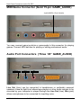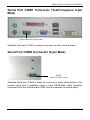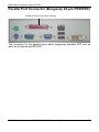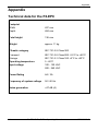
1
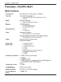
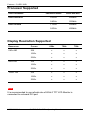
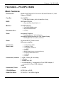
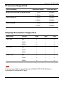
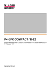
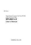
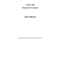
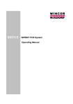
P4-EPC / B-E1, B-E2 With Socket-Based Intel Celeron, Intel Pentium IV, Mobile Intel Pentium IV Processor - M Operating Manual P4-EPC / B-E1, B-E2 Operating Manual Edition Feb 2006 NO PART OF THIS MANUAL, INCLUDING THE PRODUCTS AND SOFTWARE DESCRIBED IN IT, MAY BE REPRODUCED, TRANSMITTED, TRANSCRIBED, STORED IN A RETRIEVAL SYSTEM, OR TRANSLATED INTO ANY LANGUAGE IN ANY FORM OR BY ANY MEANS, EXCEPT DOCUMENTATION KEPT BY THE PURCHASER FOR BACKUP PURPOSES, WITHOUT THE EXPRESS WRITTEN PERMISSION OF MANUFACTURER. MANUFACTURER PROVIDES THIS MANUAL “AS IS” WITHOUT WARRANTY OF ANY KIND, EITHER EXPRESS OR IMPLIED, INCLUDING BUT NOT LIMITED TO THE IMPLIED WARRANTIES OR CONDITIONS OF MERCHANTABILITY OR FITNESS FOR A PARTICULAR PURPOSE. IN NO EVENT SHALL MANUFACTURER, ITS DIRECTORS, OFFICERS, EMPLOYEES OR AGENTS BE LIABLE FOR ANY INDIRECT. SPECIAL, INCIDENTAL, OR CONSEQUENTIAL DAMAGES (INCLUDING DAMAGES FOR LOSS OF PROFITS, LOSS OF BUSINESS, LOSS OF USE OR DATA, INTERUPTION OF BUSINESS AND THE LIKE), EVEN IF MANUFACTURER HAS BEEN ADVISED OF THE POSSIBILITY OF SUCH DAMAGES ARISING FROM ANY DEFECT OR ERROR IN THIS MANUAL OR PRODUCT. PRODUCTS AND CORPORATE NAMES APPEARING IN THIS MANUAL MAY OR MAY NOT BE REGISTERED TRADEMARKS OR COPYRIGHTS OF THEIR RESPECTIVE COMPANIES, AND ARE USED ONLY FOR IDENTIFICATION OR EXPLANATION AND TO THE OWNER’S BENEFIT, WITHOUT INTENT TO INFRINGE IBM, IBM PC, IBM PC/AT, PC-DOS, OS/2 AND OS/2 WARP ARE REGISTERED TRADEMARKS OF INTERNATIONAL BUSINESS MACHINES CORPORATION. MS-DOS, WINDOWS, WINDOWS NT, WINDOWS 98 AND WINDOWS 95 ARE REGISTERED TRADEMARKS OF MICROSOFT CORPORATION. AWARD BIOS IS A PRODUCT OF AWARD SOFTWARE INC. THIRD-PARTY BRANDS AND NAMES MENTIONED IN THIS USER’S GUIDE ARE THE PROPERTY OF THEIR RESPECTIVE OWNERS. SPECIFICATIONS AND INFORMATION CONTAINED IN THIS MANUAL ARE FURNISHED FOR INFORMATION USE ONLY, AND ARE SUBJECT TO CHANGE AT ANY TIME WITHOUT NOTICE, AND SHOULD NOT BE CONSTURED AS A COMMITMENT BY MANUFACTURER. MANUFACTURER ASSUMES NO RESPONSIBILITY OR LIABILITY FOR ANY ERRORS OR INACCURACIES THAT MAY APPEAR IN THIS MANUAL, INCLUDING THE PRODUCTS AND SOFTWARE DESCRIBED IN IT. BEETLE™ IS A REGISTERED TRADEMARK OF WINCOR NIXDORF GMBH & CO. KG CELERON™ IS A REGISTERED TRADEMARK OF THE INTEL CORPORATION PENTIUM™ IS A REGISTERED TRADEMARK OF THE INTEL CORPORATION COPYRIGHT © 2005 MANUFACTURER ALL RIGHTS RESERVED. DELIVERY SUBJECT TO AVAILABILITY; TECHNICAL MODIFICATIONS POSSIBLE. Contents Contents MANUFACTURER’S CERTIFICATION ..................................................1 T ESTED SAFETY ...........................................................................................1 FCC-CLASS A DECLARATION........................................................................1 NOTE ON THE LASER .....................................................................................1 IMPORTANT NOTES........................................................................................2 REPLACING THE LITHIUM BATTERY.................................................................3 POWER CORD SELECTION .............................................................................4 FEATURES – P4-EPC /B-E1...........................................................7 MAIN FEATURES ...........................................................................................7 PROCESSOR SUPPORTED ..............................................................................9 DISPLAY RESOLUTION SUPPORTED ................................................................9 FEATURES – P4-EPC /B-E2.........................................................10 MAIN FEATURES .........................................................................................10 PROCESSOR SUPPORTED ............................................................................12 DISPLAY RESOLUTION SUPPORTED ..............................................................12 FUNCTIONS & INDICATORS ON THE P4-EPC...................................13 1 – ON/OFF BUTTON .................................................................................13 2 – RESET SWITCH ...................................................................................13 3 – POWER-ON INDICATOR .......................................................................13 4 – HARD-DISK I NDICATOR .......................................................................13 5 – FLOPPY-DISK INDICATOR ...................................................................13 6 – CD-ROM INDICATOR ............................................................................13 7 – USB CONNECTOR (FRONT PANEL) .........................................................14 DRIVES ON THE P4-EPC...............................................................15 FLOPPY DRIVE ...........................................................................................15 HARD-DISK DRIVE ......................................................................................15 CD-ROM/DVD DRIVE ................................................................................15 BACK PANEL CONNECTORS ON THE P4-EPC.................................16 POWER-SUPPLY UNIT .................................................................................17 ON-BOARD DVI (TFT FLAT PANEL DISPLAY) ................................................18 VGA CONNECTOR (BLUE 15-PIN VGA) ........................................................18 PS/2 MOUSE CONNECTOR (GREEN 6-PIN MINI-DIN) ......................................19 PS/2 KEYBOARD CONNECTOR (PURPLE 6-PIN MINI-DIN) ..............................19 USB PORTS 1 & 2 (T WO 4-PIN UNIVERSAL SERIAL BUS) ...............................20 01750100230 C P4-EPC /BE1, B-E2 – Operating Manual Contents USB PORTS 3 & 4 (T WO 4-PIN UNIVERSAL SERIAL BUS) ...............................20 MIDI/GAME CONNECTOR (GOLD 15-PIN GAME_AUDIO)..............................21 AUDIO PORT CONNECTORS (T HREE 1/8” GAME_AUDIO)............................21 SERIAL PORT COM1 CONNECTOR (T EAL/T URQUOISE 9-PIN MALE).................22 SERIAL PORT COM2 CONNECTOR (9-PIN MALE) ...........................................22 PARALLEL PORT CONNECTOR (BURGUNDY 25-PIN PRINTER) .......................23 APPENDIX ....................................................................................24 T ECHNICAL DATA FOR THE P4-EPC .............................................................24 MODEL TYPE AND SERIES FOR P4-EPC .......................................................25 01750100230 C P4-EPC /BE1, B-E2 – Operating Manual Manufacturer’s Certification Manufacturer’s Certification The device complies with the requirements of the EEC directive 89/336/EEC with regard to “Electromagnetic compatibility” and 73/23/ECC “Low Voltage Directive”. Therefore, you will find the CE mark on the device or packaging. Tested Safety In addition, the P4-EPC has received the UL symbol and cUL symbol. FCC-Class A Declaration This equipment has been tested and found to comply with the limits for a Class A digital device, pursuant to part 15 of the FCC Rules. These limits are designed to provide reasonable protection against harmful interference when the equipment is operated in a commercial environment. This equipment generates, uses, and can radiate radio frequency energy and, if not installed and used in accordance with the instruction manual, may cause harmful interference to radio communications. Operation of this equipment in a residential area is likely to cause harmful interference in which case the user will be required to correct the interference at his own expense. Modifications not authorized by the manufacturer may void users authority to operate this device. This Class A digital apparatus complies with Canadian ICES-003. Cet appareil numérique de la classe A est conforme à la norme NBM-003 du Canada. Note on the laser If your device is equipped with a CD-ROM drive, the following condition applies: The CD ROM drive contains a light-emitting diode (LED), classified according to IEC 825-1:1993:LASER CLASS 1; it must not be opened. 01750100230 C P4-EPC /B-E1, B-E2 – Operating Manual 1 Important notes Important notes The P4-EPC system is a computer for manufacturer’s usage. It is conforming to the current safety standards for data processing equipment. If this device is taken from a cold environment into the operating room, moisture condensation may form. The device must be absolutely dry before being put into service; an acclimatization period of at least two hours must therefore be observed, This device is equipped with a safety-tested power cable and may be connected only to a prescribed grounded-contact power socket. When setting up the device, ensure that the power socket on the device and the grounded-contact power socket are easily accessible. To disconnect the device from the supply voltage completely, switch off the device and disconnect the power plug. Ensure that no foreign objects (e.g. office clips) find their way into the device, as this may lead to electric shocks or short-circuits. In order to ensure that the device is well ventilated and to prevent over heating, do not obstruct the ventilation slots on your device. Never plug in or unplug data communication lines during thunderstorms. Protect devices from vibrations, dust, moisture and heat. Always dispose of used parts in an environmentally safe manner. In emergencies (e.g. damaged housing or damaged power cable, penetration by liquids or foreign bodies), the device must be switched off immediately, the power plug disconnected and the Customer Service of Wincor Nixdorf (WN) or your dealer must be notified. Your P4-EPC system is the result of modern technical innovation. So please see for according structural and technical surroundings to guarantee a faultless and efficient work of your system. WARNINGS: The device may only be repaired by authorized qualified personnel. Unauthorized opening of the device and inexpertly carried-out repairs may not only seriously jeopardize the safety of the user, but also cancel all warranty and liability agreements. 2 P4-EPC /B-E1, B-E2 – Operating Manual 1750100230 C Replacing the Lithium battery Replacing the Lithium Battery CAUTION: Incorrect replacement of the Lithium Battery may lead to a risk of explosion The lithium battery must be replaced by the end user only by identical batteries or types recommended by Wincor Nixdorf. Do not throw Lithium Batteries into the trashcan. It must be disposed of in accordance with local regulations concerning special waste Make sure that you insert the Battery the right way round. The plus pole must be on the top! 2 u Plus-Pole 3 1 (1) Push the Latch. (2) Remove the Lithium Battery from its Socket. (3) Insert and press a new Lithium Battery of same type in the Socket. 01750100230 C P4-EPC /B-E1, B-E2 – Operating Manual 3 Power cord selection Power Cord Selection IMPORTANT: Power cord are not supplied with the equipment and consumers have to use certified power cord, for example, 1) CCC for China 2) UL, cUL and CSA for North America 3) Certified power cord approved by home governing body for Continental Europe, UK and Australia The power cord for this unit has to select according to the country of destination. It must be used to prevent electric shock. Use the following guidelines if it is necessary to replace the original cord set. The female receptacle of the cord set must meet CEE-22 requirements (see above Figure). For the United States and Canada Use a UL listed and CSA labeled cord set consisting of a three-conductor cord with a maximum length of 15 feet. For units, which stand on a desk or table, type SVT or SJT cord sets shall be used. For units, which stand on floor, only SJT type cord sets shall be used. The cord set must be selected according to the current rating for your unit. Please consult Table A for the selection criteria for power cords used in the United States and Canada. 4 P4-EPC /B-E1, B-E2 – Operating Manual 1750100230 C Power cord selection Table A: Cord Type Size of Conductors in Cord Maximum Current Rating of Unit SJT 18 AWG 16 AWG 10 Amps 12 Amps 14 AWG 12 Amps 18 AWG 10 Amps 17 AWG 12 Amps SVT For units set at 115 V: Use a parallel blade, grounding type attachment plug rated 15 A, 125 V. For units set at 230 V (domestic use): Use a tandem blade, grounding type attachment plug rated 15 A, 250 V. 01750100230 C P4-EPC /B-E1, B-E2 – Operating Manual 5 Power cord selection For units set at 230 V (outside of the United States and Canada): Use a cord set consisting of a minimum AWG according to Table A and a grounding type attachment plug rated 15 A, 250 V. The cord set should have the appropriate safety approvals for the country in which the equipment will be installed and should be marked HAR. For the United Kingdom Should the plug on the flexible cord not be of the type for your socket outlets, do not use an adapter but remove the plug from the cord and discard. Carefully prepare the end of the supply cord and fit a suitable plug. WARNING: THIS APPLIANCE MUST BE EARTHED. IMPORTANT: The wires in this main lead are colored in accordance with the following code: Green and Yellow: Blue: Earth Neutral Brown: Live As the colors of the wires in the mains lead of this appliance may not correspond with the colored markings identifying the terminals in your plug, proceed as follows: The wire which is colored Green and Yellow must be connected to the terminal in the plug which is marked with the letter E or by the earth symbol or colored Green or Green and Yellow. The wire which is colored Blue must be connected to the terminal which is marked with the letter N or colored Black. The wire which is colored Brown must be connected to the terminal which is marked with the letter L or colored Red. 6 P4-EPC /B-E1, B-E2 – Operating Manual 1750100230 C Features – P4-EPC /B-E1 FEATURES – P4-EPC /B-E1 Main Features PROCESSORS Intel Pentium IV, Intel Celeron, PGA478 CHIP SET Intel 845G, Brookdale-G FSB 400/533 MHz (100/133 MHz Bus Clock) 4X AGP BIOS 2M Flash EPROM Plug-and-Play Specification 1.1 M EMORY 128 MB (default) Two DDR DIMM socket Support DDR133/266 EXPANSION SLOT VIDEO 5 x PCI 1 x AGP (4X) Integrated Graphics Intel Brookdale-G, Video Memory Integrated Digital interface for Flat Panel display WN Digital Flat Panel (DVI) Interface AUDIO INTERFACES, BACK PANEL INTERFACES, INTERNAL On-board AC97 Codec sound 4W power amplifier 1 x Keyboard, PS/2 1 x Mouse, PS/2 1 x Parallel, EPP/ECP 1 x CRT 2 x USB Audio ports (Line-in, Line-out, Mic-in) 2 x RS232 Standard Serial 1 x DVI-D 1 x LAN INTERFACES, FRONT 2 x IDE, Primary & secondary 1 x Floppy 1 x Wake-on-LAN 2 x USB Header (1 connected to Front USB Adapter, 1 connected to Rear USB Adapter) CD-in 2 x USB CD-ROM DRIVE ATAPI 52x or DVD HARD DISK DRIVE PCI IDE, 3½" 40 GB or Higher FLOPPY DISKETTE DRIVE 1.44MB, 3½" 01750100230 C P4-EPC /B-E1, B-E2 – Operating Manual 7 Features – P4-EPC /B-E1 8 POWER INPUT Nominal voltage: 100-120V / 200-240V Frequency: 50 ~ 60 Hz Current: 6/3A DIMENSIONS 136 (H) x 427 (W) x 404 (D) in mm P4-EPC /B-E1, B-E2 – Operating Manual 1750100230 C Features – P4-EPC /B-E1 Processor Supported INTEL PROCESSOR PROCESSOR SPEED FRONT SIDE BUS INTEL PENTIUM IV 2.0GHZ 400MHZ 2.8GHZ 533MHZ 1.7GHZ 400MHZ 2.0GHZ 400MHZ INTEL CELERON Display Resolution Supported RESOLUTION COLORS 640 X 480 800 X 600 1024 X 768 60HZ 72HZ 75HZ 256 X X X 16-BIT X X X 32-BIT X X X 256 X X X 16-BIT X X X 32-BIT X X X 256 X X X 16-BIT X X X 32-BIT X X X NOTE: It is recommended to use refresh rate of 60Hz if TFT LCD Monitor is connected to on-board DVI port. 01750100230 C P4-EPC /B-E1, B-E2 – Operating Manual 9 Features – P4-EPC /B-E2 FEATURES – P4-EPC /B-E2 Main Features PROCESSORS Mobile Intel Pentium IV Processor-M, Intel Pentium IV, Intel Celeron, PGA478 CHIP SET Intel 845GV FSB 400/533 MHz (100/133 MHz Bus Clock) BIOS 2M Flash EPROM Plug-and-Play Specification 1.1 M EMORY 128 MB (default) Two DDR DIMM socket Support DDR200/266 5 x PCI EXPANSION SLOT VIDEO Integrated Graphics Intel Brookdale-G, Video Memory Integrated Digital interface for Flat Panel display WN Digital Flat Panel (DVI) Interface AUDIO On-board AC97 Codec sound 4W power amplifier INTERFACES, BACK PANEL 1 x Keyboard, PS/2 1 x Mouse, PS/2 1 x Parallel, EPP/ECP 1 x CRT 4 x USB Audio ports (Line-in, Line-out, Mic-in) 2 x RS232 Standard Serial 1 x DVI-D 1 x LAN INTERFACES, INTERNAL 2 x IDE, Primary & secondary 1 x Floppy 1 x Wake-on-LAN 2 x USB Header (1 connected to Front USB Adapter, 1 connected to Rear USB Adapter) CD-in INTERFACES, FRONT 2 x USB CD-ROM DRIVE ATAPI 52x or DVD HARD DISK DRIVE PCI IDE, 3½" 40 GB or Higher 10 P4-EPC /B-E1, B-E2 – Operating Manual 1750100230 C Features – P4-EPC /B-E2 FLOPPY DISKETTE DRIVE 1.44MB, 3½" POWER INPUT Nominal voltage: 100-120V / 200-240V Frequency: 50 ~ 60 Hz Current: 6/3A DIMENSIONS 136 (H) x 427 (W) x 404 (D) in mm 01750100230 C P4-EPC /B-E1, B-E2 – Operating Manual 11 Features – P4-EPC /B-E2 Processor Supported INTEL PROCESSOR M OBILE INTEL PENTIUM IV PROCESSOR-M INTEL PENTIUM IV INTEL CELERON PROCESSOR SPEED FRONT SIDE BUS 1.7GHZ 400MHZ 2.2GHZ 400MHZ 2.0GHZ 400MHZ 2.8GHZ 533MHZ 1.7GHZ 400MHZ 2.0GHZ 400MHZ Display Resolution Supported RESOLUTION COLORS 640 X 480 800 X 600 1024 X 768 60HZ 72HZ 75HZ 256 X X X 16-BIT X X X 32-BIT X X X 256 X X X 16-BIT X X X 32-BIT X X X 256 X X X 16-BIT X X X 32-BIT X X X NOTE: It is recommended to use refresh rate of 60Hz if TFT LCD Monitor is connected to on-board DVI port. 12 P4-EPC /B-E1, B-E2 – Operating Manual 1750100230 C Functions & Indicators on the P4-EPC FUNCTIONS & INDICATORS ON THE P4-EPC 6 5 2 4 3 1 7 1 – ON/OFF Button In an ATX based system, the new soft touch power button replaces the main power switch that turns your system on and off. From an OFF state, you can switch the system ON by simply pressing the power button. From an ON state, pressing and holding the power button for four (4) seconds can turn OFF the system. The functions of the power button can also be altered in the Power Management section of the CMOS setup. 2 – RESET Switch Insert a small, metal rod (an unwound paperclip for example) into this hole to perform System Reset 3 – POWER-ON Indicator The indicator lights up green when the system unit is switched on. 4 – HARD-DISK Indicator The indicator lights up when the Hard-Disk drive of the system unit is accessed. 5 – FLOPPY-DISK Indicator The indicator lights up when the Floppy-Disk drive of the system unit is accessed. 6 – CD-ROM Indicator The indicator lights up when the CD-ROM drive of the system unit is accessed. 01750100230 C P4-EPC /B-E1, B-E2 – Operating Manual 13 Functions & Indicators on the P4-EPC 7 – USB Connector (Front Panel) Two contact points are meant for connection of Universal Serial Bus (USB) Devices. 14 P4-EPC /B-E1, B-E2 – Operating Manual 1750100230 C Drives on the P4-EPC DRIVES ON THE P4-EPC 5¼" CD-ROM DRIVE 3½" HDD 3½" FDD The P4-EPC has two drive slots for externally accessible drives. Two further 3.5" drive slots are available for the installation of hard disks. The following drives may be used in the P4-EPC: 3½" drive slot for Floppy Drive 3½" Hard-Disk Drive 5¼" drive slot for CD-ROM or DVD-ROM Drive Floppy Drive The 3½" Floppy Drive supports capacities of up to 1.44 MB. This drive bay can also be optionally used for other 3½" drives such as streamer drives. Hard-Disk Drive P4-EPC systems can be equipped with one 3½" E-IDE hard disks. The storage capacity is changed in line with market demand, but is currently at least 40GB. CD-ROM/DVD Drive The P4-EPC offers an optional 5¼" CD-ROM or DVD-ROM drive. This drive supports the use of CD-ROM media as inexpensive, non-alterable data media for software distribution or as permanent data storage for graphics, videos or other application data. 01750100230 C P4-EPC /B-E1, B-E2 – Operating Manual 15 Back Panel Connectors on the P4-EPC PCI-SLOT #5 PCI-SLOT #4 PCI-SLOT #3 PCI-SLOT #2 PCI-SLOT #1 2x USB Slot +12V Supply at 2A (max) Game and Audio Port BACK PANEL CONNECTORS ON THE P4-EPC COM 6* POWER-SUPPLY UNIT COM 5* COM 2 Mouse Keyboard 16 Parallel Port COM1 LAN RJ45 CRT 2 x USB P4-EPC /B-E1, B-E2 – Operating Manual DVI Connector 1750100230 C Back Panel Connectors on the P4-EPC Power-Supply Unit Power Supply Specification AC Out AC INPUT LIVE-VOLTAGE WIPER-SWITCH TYPE NOMINAL VOLTAGE Standard SFX switching CURRENT 6/3A FREQUENCY AC IN SELECTION 50 / 60 Hz Wiper-Switch AC O UT Yes POWER ON-OFF SWITCH No APPROVAL EN61000 100-120V / 200-240V W ARNINGS: Before connecting the P4-EPC system unit to the line voltage, if the rated voltage does not agree with the local line voltage, you must move the wiper switch to the correct position. 115 = 100 V TO 120 V 230 = 200 V to 240 V 01750100230 C P4-EPC /B-E1, B-E2 – Operating Manual 17 Back Panel Connectors on the P4-EPC On-board DVI (TFT Flat Panel Display) DVI-D Connector The motherboard has an on-board DVI-D connector supporting standard DVI digital flat panel display. The on-board Silicon Image SiI164 transmitter encode the digital output from the Intel DVO interface of the 845GV to TMDS output for the DVI interface. It is capable of driving a digital display up to 1024x768 at 60Hz. VGA Connector (Blue 15-pin VGA) VGA Connector (15-pin) The motherboard shall have internal graphics accelerator (Intel Brookdale-G) to provide simultaneous video output to a VGA-compatible device via an onboard 15-pin DSUB and to a TFT Flat Panel LCD display. The internal graphics can support up to a maximum resolution of 1024x768 at 60Hz resolutions. 18 P4-EPC /B-E1, B-E2 – Operating Manual 1750100230 C Back Panel Connectors on the P4-EPC PS/2 Mouse Connector (Green 6-pin Mini-DIN) PS/2 Mouse (6-pin Female) This connector is for a standard Mouse using a PS/2 plug (mini DIN). PS/2 Keyboard Connector (Purple 6-pin Mini-DIN) PS/2 Keyboard (6-pin Female) This connector is for a standard Keyboard using a PS/2 plug (mini DIN). 01750100230 C P4-EPC /B-E1, B-E2 – Operating Manual 19 Back Panel Connectors on the P4-EPC USB Ports 1 & 2 (Two 4-pin Universal Serial Bus) USB1 Universal Serial Bus (USB) 2 Two USB ports are available for connecting USB devices. USB Ports 3 & 4 (Two 4-pin Universal Serial Bus) USB3 USB4 Two USB ports are available for connecting USB devices. 20 P4-EPC /B-E1, B-E2 – Operating Manual 1750100230 C Back Panel Connectors on the P4-EPC MIDI/Game Connector (Gold 15-pin GAME_AUDIO) Joystick/MIDI (15-pin female) You may connect game joysticks or game-pads to this connector for playing games. Connect MIDI devices for playing or editing professional audio. Audio Port Connectors (Three 1/8” GAME_AUDIO) Line Out Line In MIC Line Out (lime) can be connected to headphones or preferably powered speakers. Line In (light blue) allows tape players or other audio sources to be recorded by your computer or played through the Line Out (lime). Mic (pink) allows microphones to be connected for inputting voice. 01750100230 C P4-EPC /B-E1, B-E2 – Operating Manual 21 Back Panel Connectors on the P4-EPC Serial Port COM1 Connector (Teal/Turquoise 9-pin Male) COM1 Serial Port (9-pin male) Standard Serial port COM1 is ready for a mouse or other serial devices. Serial Port COM2 Connector (9-pin Male) COM 2 Serial Port (9-pin male) Standard Serial port COM2 is ready for a mouse or other serial devices. This second serial port is available using a 9-pin DSUB-Male cable assembly connected from the motherboard COM2 dual-row headers to a back panel. 22 P4-EPC /B-E1, B-E2 – Operating Manual 1750100230 C Back Panel Connectors on the P4-EPC Parallel Port Connector (Burgundy 25-pin PRINTER) Parallel (Printer) Port (25-pin female) The connector for the parallel ports which supporting standard SPP and as wells as bi-directional EPP/ECP. 01750100230 C P4-EPC /B-E1, B-E2 – Operating Manual 23 Appendix Appendix Technical data for the P4-EPC Footprint Width Depth 427 mm 404 mm Total height 136 mm Weight approx. 11 kg Climatic category IEC 721-3-3 Class 3K3 Transport Storage Operating temperature Input voltage IEC 721-3-2 Class 2K2 -2.5°C to +60°C IEC 721-3-1 Class 1K2 +5°C to +40°C 5 - 40°C 100 - 120 VAC 200 - 240 VAC Power Rating 6A / 3A Frequency of system voltage 50 / 60 Hz Noise generation <47 dB (A) 24 P4-EPC /B-E1, B-E2 – Operating Manual 1750100230 C Appendix Model Type and Series for P4-EPC Model Type / Series Description P4-EPC /B-E1 Used metal enclosure except top and bottom, with vent openings on left and rear side. With additional vent openings on front bezel. System using P195 motherboard. P4-EPC /B-E2 Used metal enclosure except top and bottom, with vent openings on left and rear side. With additional vent openings on front bezel. System using P195+ motherboard. 01750100230 C P4-EPC /B-E1, B-E2 – Operating Manual 25 Published by Wincor Nixdorf Pte Ltd 2, Kallang Sector Singapore 349277 Part No.: 01750100230 C Printed in Singapore