1
Reference Guide
Read this guide first.
Please read this guide before operating this equipment.
After you finish reading this guide, store it in a safe place for future reference.
ENG
0
Ot¯
CLC3220/iR C3220N
Reference Guide
Manuals for the Machine
The manuals for this machine are divided as follows. Please refer to them for detailed information.
The manuals supplied with optional equipment are included in the list below. Depending on the system
configuration and product purchased, some manuals may not be needed.
Guides with this symbol are printed manuals.
• Basic Information
• Basic Operations
• Troubleshooting
• Copying and Mail Box Instructions
• Sending and Fax Instructions
• Setting Up the Network Connection and Installing
the CD-ROM Software
• Remote User Interface Instructions
• Network Connectivity and Setup Instructions
• Color Network ScanGear Installation and
Instructions
• PS/PCL/UFR Printer Instructions
• PCL Printer Driver Installation and Instructions
• PS Printer Driver Installation and Instructions
• Mac OS X PS Printer Driver Installation and
Instructions
• UFR Printer Driver Installation and Instructions
Guides with this symbol are PDF manuals included on the
accompanying CD-ROM.
User's Guide
Reference Guide
(This Document)
CD-ROM
Copying and Mail Box
Guide
CD-ROM
Sending and Facsimile
Guide
CD-ROM
Network Quick Start
Guide
Remote UI Guide
CD-ROM
Network Guide
CD-ROM
Color Network ScanGear
User's Guide
CD-ROM
PS/PCL/UFR Printer
Guide
CD-ROM
PCL Driver Guide
CD-ROM
PS Driver Guide
CD-ROM
Mac PS Driver Guide
CD-ROM
UFR Driver Guide
CD-ROM
• Fax Driver Installation and Instructions
• Installing MEAP Applications and
Using the Login Service
Fax Driver Guide
CD-ROM
MEAP SMS Administrator
Guide
CD-ROM
To view the manual in PDF format, Adobe Reader/Adobe Acrobat Reader is required. If Adobe Reader/Adobe Acrobat Reader is not installed on your
system, please download it from the Adobe Systems Incorporated website.
How This Manual Is Organized
Chapter 1
Before You Start Using This Machine
Chapter 2
Basic Operations
Chapter 3
Optional Equipment
Chapter 4
Customizing Settings
Chapter 5
Checking Job and Device Status
Chapter 6
System Manager Settings
Chapter 7
Routine Maintenance
Chapter 8
Troubleshooting
Chapter 9
Appendix
Includes the specifications of the main unit and optional equipment, the Relationship between
Original Orientation and Preprinted Paper Output Chart, and index.
Considerable effort has been made to ensure that this manual is free of inaccuracies and omissions. However, as we are constantly improving our
products, if you need an exact specification, please contact Canon.
Contents
Preface . . . . . . . . . . . . . . . . . . . . . . . . . . . . . . . . . . . . . . . . . . . . . . . . . . . . . . . . . . . . . . . . . . xi
How To Use This Manual. . . . . . . . . . . . . . . . . . . . . . . . . . . . . . . . . . . . . . . . . . . . . . . . . . . . xi
Symbols Used in This Manual. . . . . . . . . . . . . . . . . . . . . . . . . . . . . . . . . . . . . . . . . . . . . . xi
Keys Used in This Manual. . . . . . . . . . . . . . . . . . . . . . . . . . . . . . . . . . . . . . . . . . . . . . . . . xii
Displays Used in This Manual . . . . . . . . . . . . . . . . . . . . . . . . . . . . . . . . . . . . . . . . . . . . . . xii
Illustrations Used in This Manual . . . . . . . . . . . . . . . . . . . . . . . . . . . . . . . . . . . . . . . . . . xiii
Operations and Terms Used in This Manual . . . . . . . . . . . . . . . . . . . . . . . . . . . . . . . . . . . xiv
Legal Notices . . . . . . . . . . . . . . . . . . . . . . . . . . . . . . . . . . . . . . . . . . . . . . . . . . . . . . . . . . . . xvi
Preventing Counterfeit Documents . . . . . . . . . . . . . . . . . . . . . . . . . . . . . . . . . . . . . . . . . xvi
R & TTE Directive . . . . . . . . . . . . . . . . . . . . . . . . . . . . . . . . . . . . . . . . . . . . . . . . . . . . . . xvi
Laser Safety . . . . . . . . . . . . . . . . . . . . . . . . . . . . . . . . . . . . . . . . . . . . . . . . . . . . . . . . . . xvi
Additional Information . . . . . . . . . . . . . . . . . . . . . . . . . . . . . . . . . . . . . . . . . . . . . . . . . . . xvii
Abbreviations Used in This Manual . . . . . . . . . . . . . . . . . . . . . . . . . . . . . . . . . . . . . . . . .xviii
Trademarks . . . . . . . . . . . . . . . . . . . . . . . . . . . . . . . . . . . . . . . . . . . . . . . . . . . . . . . . . . .xviii
Copyright . . . . . . . . . . . . . . . . . . . . . . . . . . . . . . . . . . . . . . . . . . . . . . . . . . . . . . . . . . . . . xix
Disclaimers . . . . . . . . . . . . . . . . . . . . . . . . . . . . . . . . . . . . . . . . . . . . . . . . . . . . . . . . . . . xix
Legal Limitations on the Usage of Your Product and the Use of Images . . . . . . . . . . . . . xx
Important Safety Instructions. . . . . . . . . . . . . . . . . . . . . . . . . . . . . . . . . . . . . . . . . . . . . . .xxii
Installation . . . . . . . . . . . . . . . . . . . . . . . . . . . . . . . . . . . . . . . . . . . . . . . . . . . . . . . . . . . . xxii
Power Supply . . . . . . . . . . . . . . . . . . . . . . . . . . . . . . . . . . . . . . . . . . . . . . . . . . . . . . . . xxiv
Handling . . . . . . . . . . . . . . . . . . . . . . . . . . . . . . . . . . . . . . . . . . . . . . . . . . . . . . . . . . . . . xxv
Maintenance and Inspections . . . . . . . . . . . . . . . . . . . . . . . . . . . . . . . . . . . . . . . . . . . . xxvii
Consumables . . . . . . . . . . . . . . . . . . . . . . . . . . . . . . . . . . . . . . . . . . . . . . . . . . . . . . . .xxviii
Other Warnings . . . . . . . . . . . . . . . . . . . . . . . . . . . . . . . . . . . . . . . . . . . . . . . . . . . . . . .xxviii
Periodic Inspection of the Breaker . . . . . . . . . . . . . . . . . . . . . . . . . . . . . . . . . . . . . . . . . xxix
Checking the Breaker . . . . . . . . . . . . . . . . . . . . . . . . . . . . . . . . . . . . . . . . . . . . . . . . . . xxix
Check Sheet for the Periodic Inspection of the Breaker . . . . . . . . . . . . . . . . . . . . . . . .xxxii
Chapter 1
Before You Start Using This Machine
Installation Location and Handling . . . . . . . . . . . . . . . . . . . . . . . . . . . . . . . . . . . . . . . . . . 1-2
Installation Precautions . . . . . . . . . . . . . . . . . . . . . . . . . . . . . . . . . . . . . . . . . . . . . . . . . . 1-2
Avoid Installing the Machine in the Following Locations . . . . . . . . . . . . . . . . . . . . . . 1-2
Select a Safe Power Supply . . . . . . . . . . . . . . . . . . . . . . . . . . . . . . . . . . . . . . . . . . . 1-5
Provide Adequate Installation Space . . . . . . . . . . . . . . . . . . . . . . . . . . . . . . . . . . . . 1-6
Moving the Machine . . . . . . . . . . . . . . . . . . . . . . . . . . . . . . . . . . . . . . . . . . . . . . . . . 1-7
Handling Precautions . . . . . . . . . . . . . . . . . . . . . . . . . . . . . . . . . . . . . . . . . . . . . . . . . . . 1-7
Parts and Their Functions . . . . . . . . . . . . . . . . . . . . . . . . . . . . . . . . . . . . . . . . . . . . . . . . 1-10
External View . . . . . . . . . . . . . . . . . . . . . . . . . . . . . . . . . . . . . . . . . . . . . . . . . . . . . . . . 1-10
Internal View . . . . . . . . . . . . . . . . . . . . . . . . . . . . . . . . . . . . . . . . . . . . . . . . . . . . . . . . . 1-12
Control Panel Parts and Functions . . . . . . . . . . . . . . . . . . . . . . . . . . . . . . . . . . . . . . . . 1-14
Main Power and Control Panel Power . . . . . . . . . . . . . . . . . . . . . . . . . . . . . . . . . . . . . . . 1-15
How to Turn ON the Main Power . . . . . . . . . . . . . . . . . . . . . . . . . . . . . . . . . . . . . . . . . . 1-15
Control Panel Power Switch . . . . . . . . . . . . . . . . . . . . . . . . . . . . . . . . . . . . . . . . . . . . . 1-23
System Settings. . . . . . . . . . . . . . . . . . . . . . . . . . . . . . . . . . . . . . . . . . . . . . . . . . . . . . . . . 1-24
Description Clause . . . . . . . . . . . . . . . . . . . . . . . . . . . . . . . . . . . . . . . . . . . . . . . . . . . . 1-24
v
Chapter 2
Basic Operations
What This Machine Can Do . . . . . . . . . . . . . . . . . . . . . . . . . . . . . . . . . . . . . . . . . . . . . . . . 2-2
Overview of the CLC3220/iR C3220N . . . . . . . . . . . . . . . . . . . . . . . . . . . . . . . . . . . . . . . . 2-6
The Touch Panel Display . . . . . . . . . . . . . . . . . . . . . . . . . . . . . . . . . . . . . . . . . . . . . . . . 2-6
Switching the Functions Indicated on the Touch Panel Display . . . . . . . . . . . . . . . . 2-7
Various Touch Panel Display Screens . . . . . . . . . . . . . . . . . . . . . . . . . . . . . . . . . . . 2-9
Adding New Functions . . . . . . . . . . . . . . . . . . . . . . . . . . . . . . . . . . . . . . . . . . . . . . . . . 2-10
Specifying Settings. . . . . . . . . . . . . . . . . . . . . . . . . . . . . . . . . . . . . . . . . . . . . . . . . . . . 2-12
Functions That Conserve Power . . . . . . . . . . . . . . . . . . . . . . . . . . . . . . . . . . . . . . . . . 2-13
Checking, Changing, and Cancelling Print Jobs . . . . . . . . . . . . . . . . . . . . . . . . . . . . . 2-15
Displaying a Help Screen . . . . . . . . . . . . . . . . . . . . . . . . . . . . . . . . . . . . . . . . . . . . . . . 2-17
Reading Messages from the System Manager . . . . . . . . . . . . . . . . . . . . . . . . . . . . . . 2-19
Types of Message Boards . . . . . . . . . . . . . . . . . . . . . . . . . . . . . . . . . . . . . . . . . . . 2-19
Other Useful Functions . . . . . . . . . . . . . . . . . . . . . . . . . . . . . . . . . . . . . . . . . . . . . . . . 2-21
Using the Touch Panel Display . . . . . . . . . . . . . . . . . . . . . . . . . . . . . . . . . . . . . . . . . . . .
Frequently Used Keys . . . . . . . . . . . . . . . . . . . . . . . . . . . . . . . . . . . . . . . . . . . . . . . . .
Touch Panel Key Display . . . . . . . . . . . . . . . . . . . . . . . . . . . . . . . . . . . . . . . . . . . . . . .
Adjusting the Brightness . . . . . . . . . . . . . . . . . . . . . . . . . . . . . . . . . . . . . . . . . . . . . . .
2-24
2-24
2-25
2-27
Entering Characters from the Touch Panel Display . . . . . . . . . . . . . . . . . . . . . . . . . . .
Alphanumeric Characters. . . . . . . . . . . . . . . . . . . . . . . . . . . . . . . . . . . . . . . . . . . . . . .
Symbols . . . . . . . . . . . . . . . . . . . . . . . . . . . . . . . . . . . . . . . . . . . . . . . . . . . . . . . . . . . .
Values in Inches . . . . . . . . . . . . . . . . . . . . . . . . . . . . . . . . . . . . . . . . . . . . . . . . . . . . . .
2-28
2-28
2-30
2-32
Entering the Department ID and Password . . . . . . . . . . . . . . . . . . . . . . . . . . . . . . . . . . 2-33
Using a Login Service . . . . . . . . . . . . . . . . . . . . . . . . . . . . . . . . . . . . . . . . . . . . . . . . . . . 2-36
Placing Originals . . . . . . . . . . . . . . . . . . . . . . . . . . . . . . . . . . . . . . . . . . . . . . . . . . . . . . .
Document Sizes . . . . . . . . . . . . . . . . . . . . . . . . . . . . . . . . . . . . . . . . . . . . . . . . . . . . . .
Orientation . . . . . . . . . . . . . . . . . . . . . . . . . . . . . . . . . . . . . . . . . . . . . . . . . . . . . . . . . .
Platen Glass. . . . . . . . . . . . . . . . . . . . . . . . . . . . . . . . . . . . . . . . . . . . . . . . . . . . . . . . .
Feeder (DADF-K1) . . . . . . . . . . . . . . . . . . . . . . . . . . . . . . . . . . . . . . . . . . . . . . . . . . . .
2-40
2-40
2-41
2-42
2-46
Making Prints Using the Stack Bypass . . . . . . . . . . . . . . . . . . . . . . . . . . . . . . . . . . . . . 2-49
Multifunctional Operations . . . . . . . . . . . . . . . . . . . . . . . . . . . . . . . . . . . . . . . . . . . . . . . 2-62
Available Paper Stock . . . . . . . . . . . . . . . . . . . . . . . . . . . . . . . . . . . . . . . . . . . . . . . . . . . 2-64
Chapter 3
Optional Equipment
System Configuration . . . . . . . . . . . . . . . . . . . . . . . . . . . . . . . . . . . . . . . . . . . . . . . . . . . . 3-2
Optional Equipment . . . . . . . . . . . . . . . . . . . . . . . . . . . . . . . . . . . . . . . . . . . . . . . . . . . . 3-2
Sample System Configurations . . . . . . . . . . . . . . . . . . . . . . . . . . . . . . . . . . . . . . . . . . . 3-4
Cassette Feeding Unit-X1 . . . . . . . . . . . . . . . . . . . . . . . . . . . . . . . . . . . . . . . . . . . . . . . . . 3-5
Parts and Their Functions . . . . . . . . . . . . . . . . . . . . . . . . . . . . . . . . . . . . . . . . . . . . . . . 3-5
Optional Accessories . . . . . . . . . . . . . . . . . . . . . . . . . . . . . . . . . . . . . . . . . . . . . . . . . . . 3-6
Paper Deck-P1. . . . . . . . . . . . . . . . . . . . . . . . . . . . . . . . . . . . . . . . . . . . . . . . . . . . . . . . . . . 3-7
Parts and Their Functions . . . . . . . . . . . . . . . . . . . . . . . . . . . . . . . . . . . . . . . . . . . . . . . 3-7
Plain Pedestal-C1 . . . . . . . . . . . . . . . . . . . . . . . . . . . . . . . . . . . . . . . . . . . . . . . . . . . . . . . . 3-8
Feeder (DADF-K1). . . . . . . . . . . . . . . . . . . . . . . . . . . . . . . . . . . . . . . . . . . . . . . . . . . . . . . . 3-9
Parts and Their Functions . . . . . . . . . . . . . . . . . . . . . . . . . . . . . . . . . . . . . . . . . . . . . . . 3-9
Color Image Reader-C1/Platen Cover Type G . . . . . . . . . . . . . . . . . . . . . . . . . . . . . . . . 3-11
Parts and Their Functions . . . . . . . . . . . . . . . . . . . . . . . . . . . . . . . . . . . . . . . . . . . . . . 3-11
Finisher-M1 . . . . . . . . . . . . . . . . . . . . . . . . . . . . . . . . . . . . . . . . . . . . . . . . . . . . . . . . . . . . 3-12
Parts and Their Functions . . . . . . . . . . . . . . . . . . . . . . . . . . . . . . . . . . . . . . . . . . . . . . 3-12
Finishing Modes . . . . . . . . . . . . . . . . . . . . . . . . . . . . . . . . . . . . . . . . . . . . . . . . . . . . . . 3-13
vi
Finisher-N1/Saddle Finisher-N2 . . . . . . . . . . . . . . . . . . . . . . . . . . . . . . . . . . . . . . . . . . . . 3-16
Parts and Their Functions . . . . . . . . . . . . . . . . . . . . . . . . . . . . . . . . . . . . . . . . . . . . . . . 3-16
Finishing Modes . . . . . . . . . . . . . . . . . . . . . . . . . . . . . . . . . . . . . . . . . . . . . . . . . . . . . . 3-17
Copy Tray Unit-H1 . . . . . . . . . . . . . . . . . . . . . . . . . . . . . . . . . . . . . . . . . . . . . . . . . . . . . . . 3-23
Parts and Their Functions . . . . . . . . . . . . . . . . . . . . . . . . . . . . . . . . . . . . . . . . . . . . . . . 3-23
Card Reader-D1 . . . . . . . . . . . . . . . . . . . . . . . . . . . . . . . . . . . . . . . . . . . . . . . . . . . . . . . . . 3-24
Procedure before Using the Machine . . . . . . . . . . . . . . . . . . . . . . . . . . . . . . . . . . . . . . 3-25
Procedure after Using the Machine. . . . . . . . . . . . . . . . . . . . . . . . . . . . . . . . . . . . . . . . 3-26
Department ID Management. . . . . . . . . . . . . . . . . . . . . . . . . . . . . . . . . . . . . . . . . . . . . 3-27
Flow of Additional Functions Operations . . . . . . . . . . . . . . . . . . . . . . . . . . . . . . . . 3-27
Changing the Password and Page Limit . . . . . . . . . . . . . . . . . . . . . . . . . . . . . . . . . 3-29
Checking the Page Counts on a Control Card . . . . . . . . . . . . . . . . . . . . . . . . . . . . 3-36
Checking and Printing Counter Information . . . . . . . . . . . . . . . . . . . . . . . . . . . . . . 3-37
Clearing Page Totals. . . . . . . . . . . . . . . . . . . . . . . . . . . . . . . . . . . . . . . . . . . . . . . . 3-40
Allowing Print and Scan Jobs with Unknown IDs . . . . . . . . . . . . . . . . . . . . . . . . . . 3-42
Allowing B&W Copy and Print Jobs without Inserting a Control
Card . . . . . . . . . . . . . . . . . . . . . . . . . . . . . . . . . . . . . . . . . . . . . . . . . . . . . . . . . . . . 3-43
Chapter 4
Customizing Settings
What Are Additional Functions? . . . . . . . . . . . . . . . . . . . . . . . . . . . . . . . . . . . . . . . . . . . . 4-2
Additional Functions Settings Table . . . . . . . . . . . . . . . . . . . . . . . . . . . . . . . . . . . . . . . . . 4-5
Specifying Common Settings. . . . . . . . . . . . . . . . . . . . . . . . . . . . . . . . . . . . . . . . . . . . . . 4-17
Initial Function at Power ON . . . . . . . . . . . . . . . . . . . . . . . . . . . . . . . . . . . . . . . . . . . . . 4-17
Default Display after Auto Clear . . . . . . . . . . . . . . . . . . . . . . . . . . . . . . . . . . . . . . . . . . 4-18
Function Order . . . . . . . . . . . . . . . . . . . . . . . . . . . . . . . . . . . . . . . . . . . . . . . . . . . . . . . 4-19
Tone Settings . . . . . . . . . . . . . . . . . . . . . . . . . . . . . . . . . . . . . . . . . . . . . . . . . . . . . . . . 4-21
Text/Photo Priority in a Black-and-White Original . . . . . . . . . . . . . . . . . . . . . . . . . . . . . 4-22
Inch Entry . . . . . . . . . . . . . . . . . . . . . . . . . . . . . . . . . . . . . . . . . . . . . . . . . . . . . . . . . . . 4-22
Auto Paper Selection/Auto Drawer Switching . . . . . . . . . . . . . . . . . . . . . . . . . . . . . . . . 4-23
Identifying the Type of Paper in a Paper Source . . . . . . . . . . . . . . . . . . . . . . . . . . . . . . 4-25
Energy Saver Mode. . . . . . . . . . . . . . . . . . . . . . . . . . . . . . . . . . . . . . . . . . . . . . . . . . . . 4-28
Energy Consumption in the Sleep Mode. . . . . . . . . . . . . . . . . . . . . . . . . . . . . . . . . . . . 4-29
Output Tray Designation . . . . . . . . . . . . . . . . . . . . . . . . . . . . . . . . . . . . . . . . . . . . . . . . 4-30
Setting the Printing Priority . . . . . . . . . . . . . . . . . . . . . . . . . . . . . . . . . . . . . . . . . . . . . . 4-34
Standard Paper for the Stack Bypass . . . . . . . . . . . . . . . . . . . . . . . . . . . . . . . . . . . . . . 4-36
Irregular Paper Size Settings for the Stack Bypass. . . . . . . . . . . . . . . . . . . . . . . . . . . . 4-41
Registering and Editing Irregular Paper Sizes . . . . . . . . . . . . . . . . . . . . . . . . . . . . 4-41
Naming a Size Key . . . . . . . . . . . . . . . . . . . . . . . . . . . . . . . . . . . . . . . . . . . . . . . . . 4-42
Erasing Irregular Paper Sizes . . . . . . . . . . . . . . . . . . . . . . . . . . . . . . . . . . . . . . . . . 4-44
Standard Local Print Settings . . . . . . . . . . . . . . . . . . . . . . . . . . . . . . . . . . . . . . . . . . . . 4-45
Changing the Language Shown on the Touch Panel Display . . . . . . . . . . . . . . . . . . . . 4-47
Reversing the Contrast of the Touch Panel Display . . . . . . . . . . . . . . . . . . . . . . . . . . . 4-48
Alternating the Print Output (Offset Jobs) . . . . . . . . . . . . . . . . . . . . . . . . . . . . . . . . . . . 4-48
Data Compression Ratio for Remote Scans . . . . . . . . . . . . . . . . . . . . . . . . . . . . . . . . . 4-49
Setting the Gamma Value for Remote Scans . . . . . . . . . . . . . . . . . . . . . . . . . . . . . . . . 4-50
Returning the Common Settings to Their Defaults . . . . . . . . . . . . . . . . . . . . . . . . . . . . 4-50
Timer Settings . . . . . . . . . . . . . . . . . . . . . . . . . . . . . . . . . . . . . . . . . . . . . . . . . . . . . . . . . . 4-51
Current Time Adjustment . . . . . . . . . . . . . . . . . . . . . . . . . . . . . . . . . . . . . . . . . . . . . . . 4-51
Auto Sleep Time . . . . . . . . . . . . . . . . . . . . . . . . . . . . . . . . . . . . . . . . . . . . . . . . . . . . . . 4-51
Auto Clear Time . . . . . . . . . . . . . . . . . . . . . . . . . . . . . . . . . . . . . . . . . . . . . . . . . . . . . . 4-52
Daily Timer Settings . . . . . . . . . . . . . . . . . . . . . . . . . . . . . . . . . . . . . . . . . . . . . . . . . . . 4-52
Low-Power Mode Time . . . . . . . . . . . . . . . . . . . . . . . . . . . . . . . . . . . . . . . . . . . . . . . . . 4-53
Adjusting the Machine . . . . . . . . . . . . . . . . . . . . . . . . . . . . . . . . . . . . . . . . . . . . . . . . . . . 4-54
Zoom Fine Adjustment . . . . . . . . . . . . . . . . . . . . . . . . . . . . . . . . . . . . . . . . . . . . . . . . . 4-54
Saddle Stitch Staple Repositioning . . . . . . . . . . . . . . . . . . . . . . . . . . . . . . . . . . . . . . . . 4-55
vii
Saddle Stitch Position Adjustment . . . . . . . . . . . . . . . . . . . . . . . . . . . . . . . . . . . . . . . .
Automatic Gradation Adjustment . . . . . . . . . . . . . . . . . . . . . . . . . . . . . . . . . . . . . . . . .
Quick Adjustment. . . . . . . . . . . . . . . . . . . . . . . . . . . . . . . . . . . . . . . . . . . . . . . . . .
Full Adjustment . . . . . . . . . . . . . . . . . . . . . . . . . . . . . . . . . . . . . . . . . . . . . . . . . . .
Exposure Recalibration . . . . . . . . . . . . . . . . . . . . . . . . . . . . . . . . . . . . . . . . . . . . . . . .
Cleaning the Inside of the Main Unit . . . . . . . . . . . . . . . . . . . . . . . . . . . . . . . . . . . . . .
Automatic Feeder Cleaning . . . . . . . . . . . . . . . . . . . . . . . . . . . . . . . . . . . . . . . . . . . . .
Chapter 5
4-56
4-57
4-57
4-58
4-61
4-61
4-62
Checking Job and Device Status
Checking the Counter . . . . . . . . . . . . . . . . . . . . . . . . . . . . . . . . . . . . . . . . . . . . . . . . . . . . 5-2
Checking Job Status . . . . . . . . . . . . . . . . . . . . . . . . . . . . . . . . . . . . . . . . . . . . . . . . . . . . . 5-6
Job Details . . . . . . . . . . . . . . . . . . . . . . . . . . . . . . . . . . . . . . . . . . . . . . . . . . . . . . . . . . . . 5-10
Checking Copy/Print Job Details . . . . . . . . . . . . . . . . . . . . . . . . . . . . . . . . . . . . . . . . . 5-10
Printing the Copy/Print Log . . . . . . . . . . . . . . . . . . . . . . . . . . . . . . . . . . . . . . . . . . . . . 5-11
Priority Printing . . . . . . . . . . . . . . . . . . . . . . . . . . . . . . . . . . . . . . . . . . . . . . . . . . . . . . . . 5-13
Handling Print Jobs Sent from Computers . . . . . . . . . . . . . . . . . . . . . . . . . . . . . . . . . . 5-15
Printing Secured Documents . . . . . . . . . . . . . . . . . . . . . . . . . . . . . . . . . . . . . . . . . . . . . 5-17
Chapter 6
System Manager Settings
Specifying the System Manager Settings . . . . . . . . . . . . . . . . . . . . . . . . . . . . . . . . . . . . 6-2
Department ID Management . . . . . . . . . . . . . . . . . . . . . . . . . . . . . . . . . . . . . . . . . . . . . . . 6-4
Registering the Department ID, Password, and Page Limit . . . . . . . . . . . . . . . . . . . . . . 6-5
Changing the Password and Page Limit . . . . . . . . . . . . . . . . . . . . . . . . . . . . . . . . . . . . 6-9
Erasing the Department ID and Password . . . . . . . . . . . . . . . . . . . . . . . . . . . . . . . . . . 6-13
Checking and Printing Counter Information . . . . . . . . . . . . . . . . . . . . . . . . . . . . . . . . . 6-15
Clearing Page Totals . . . . . . . . . . . . . . . . . . . . . . . . . . . . . . . . . . . . . . . . . . . . . . . . . . 6-18
Allowing Print and Scan Jobs with Unknown IDs . . . . . . . . . . . . . . . . . . . . . . . . . . . . . 6-20
Allowing B&W Copy and Print Jobs without Entering a Department ID . . . . . . . . . . . . 6-21
Remote UI . . . . . . . . . . . . . . . . . . . . . . . . . . . . . . . . . . . . . . . . . . . . . . . . . . . . . . . . . . . . . 6-24
Device Information Settings . . . . . . . . . . . . . . . . . . . . . . . . . . . . . . . . . . . . . . . . . . . . . . 6-25
Clearing the Message Board . . . . . . . . . . . . . . . . . . . . . . . . . . . . . . . . . . . . . . . . . . . . . . 6-26
Auto Online/Offline. . . . . . . . . . . . . . . . . . . . . . . . . . . . . . . . . . . . . . . . . . . . . . . . . . . . . . 6-27
Auto Online . . . . . . . . . . . . . . . . . . . . . . . . . . . . . . . . . . . . . . . . . . . . . . . . . . . . . . . . . 6-27
Auto Offline . . . . . . . . . . . . . . . . . . . . . . . . . . . . . . . . . . . . . . . . . . . . . . . . . . . . . . . . . 6-28
Current Data and Time . . . . . . . . . . . . . . . . . . . . . . . . . . . . . . . . . . . . . . . . . . . . . . . . . . . 6-29
Limiting Functions When the Optional Security Key Is Turned OFF. . . . . . . . . . . . . . 6-33
License Registration . . . . . . . . . . . . . . . . . . . . . . . . . . . . . . . . . . . . . . . . . . . . . . . . . . . . 6-34
MEAP Settings . . . . . . . . . . . . . . . . . . . . . . . . . . . . . . . . . . . . . . . . . . . . . . . . . . . . . . . . . 6-36
Use HTTP Server. . . . . . . . . . . . . . . . . . . . . . . . . . . . . . . . . . . . . . . . . . . . . . . . . . . . . 6-36
Printing Installed Application Information . . . . . . . . . . . . . . . . . . . . . . . . . . . . . . . . . . . 6-37
Chapter 7
Routine Maintenance
Paper Drawers. . . . . . . . . . . . . . . . . . . . . . . . . . . . . . . . . . . . . . . . . . . . . . . . . . . . . . . . . . . 7-2
Loading Paper . . . . . . . . . . . . . . . . . . . . . . . . . . . . . . . . . . . . . . . . . . . . . . . . . . . . . . . . 7-2
Adjusting a Paper Drawer to Hold a Different Paper Size . . . . . . . . . . . . . . . . . . . . . . . 7-7
Paper Deck-P1 (Optional). . . . . . . . . . . . . . . . . . . . . . . . . . . . . . . . . . . . . . . . . . . . . . . . . 7-11
Loading Paper . . . . . . . . . . . . . . . . . . . . . . . . . . . . . . . . . . . . . . . . . . . . . . . . . . . . . . . 7-11
Finisher-M1 (Optional) . . . . . . . . . . . . . . . . . . . . . . . . . . . . . . . . . . . . . . . . . . . . . . . . . . . 7-15
viii
Replacing the Staple Cartridge . . . . . . . . . . . . . . . . . . . . . . . . . . . . . . . . . . . . . . . . . . . 7-15
Finisher-N1/Saddle Finisher-N2 (Optional) . . . . . . . . . . . . . . . . . . . . . . . . . . . . . . . . . . . 7-20
Replacing the Staple Cartridge in the Stapler Unit . . . . . . . . . . . . . . . . . . . . . . . . . . . . 7-20
Replacing the Staple Cartridge in the Saddle Stitcher Unit . . . . . . . . . . . . . . . . . . . . . 7-24
Replacing the Toner Cartridge . . . . . . . . . . . . . . . . . . . . . . . . . . . . . . . . . . . . . . . . . . . . . 7-29
Replacing the Waste Toner Container . . . . . . . . . . . . . . . . . . . . . . . . . . . . . . . . . . . . . . . 7-34
Routine Cleaning . . . . . . . . . . . . . . . . . . . . . . . . . . . . . . . . . . . . . . . . . . . . . . . . . . . . . . . . 7-38
Platen Glass and Cover . . . . . . . . . . . . . . . . . . . . . . . . . . . . . . . . . . . . . . . . . . . . . . . . 7-38
Manual Feeder Cleaning . . . . . . . . . . . . . . . . . . . . . . . . . . . . . . . . . . . . . . . . . . . . . . . . 7-39
Cleaning the Inside of the Main Unit . . . . . . . . . . . . . . . . . . . . . . . . . . . . . . . . . . . . . . . 7-42
Automatic Feeder Cleaning . . . . . . . . . . . . . . . . . . . . . . . . . . . . . . . . . . . . . . . . . . . . . . 7-43
Consumables . . . . . . . . . . . . . . . . . . . . . . . . . . . . . . . . . . . . . . . . . . . . . . . . . . . . . . . . . . . 7-44
Chapter 8
Troubleshooting
Reducing the Frequency of Paper Jams . . . . . . . . . . . . . . . . . . . . . . . . . . . . . . . . . . . . . . 8-2
Clearing Paper Jams . . . . . . . . . . . . . . . . . . . . . . . . . . . . . . . . . . . . . . . . . . . . . . . . . . . . . . 8-3
Screens Indicating the Locations of Paper Jams . . . . . . . . . . . . . . . . . . . . . . . . . . . . . . 8-3
Upper Left Cover . . . . . . . . . . . . . . . . . . . . . . . . . . . . . . . . . . . . . . . . . . . . . . . . . . . . . . . 8-9
Exit Slot Cover. . . . . . . . . . . . . . . . . . . . . . . . . . . . . . . . . . . . . . . . . . . . . . . . . . . . . . . . 8-11
Fixing Unit (Inside the Main Unit) . . . . . . . . . . . . . . . . . . . . . . . . . . . . . . . . . . . . . . . . . 8-15
Duplexing Unit (Inside the Main Unit) . . . . . . . . . . . . . . . . . . . . . . . . . . . . . . . . . . . . . . 8-19
Stack Bypass. . . . . . . . . . . . . . . . . . . . . . . . . . . . . . . . . . . . . . . . . . . . . . . . . . . . . . . . . 8-22
Right Cover/Paper Drawers. . . . . . . . . . . . . . . . . . . . . . . . . . . . . . . . . . . . . . . . . . . . . . 8-26
Transport Unit (Inside the Main Unit). . . . . . . . . . . . . . . . . . . . . . . . . . . . . . . . . . . . . . . 8-30
Cassette Feeding Unit-X1 (Optional) . . . . . . . . . . . . . . . . . . . . . . . . . . . . . . . . . . . . . . 8-34
Paper Deck-P1 (Optional) . . . . . . . . . . . . . . . . . . . . . . . . . . . . . . . . . . . . . . . . . . . . . . . 8-38
Feeder (DADF-K1) (Optional) . . . . . . . . . . . . . . . . . . . . . . . . . . . . . . . . . . . . . . . . . . . . 8-41
Finisher-M1 (Optional) . . . . . . . . . . . . . . . . . . . . . . . . . . . . . . . . . . . . . . . . . . . . . . . . . 8-45
Finisher-N1/Saddle Finisher-N2 (Optional) . . . . . . . . . . . . . . . . . . . . . . . . . . . . . . . . . . 8-49
Saddle Stitcher Unit (Optional) . . . . . . . . . . . . . . . . . . . . . . . . . . . . . . . . . . . . . . . . . . . 8-53
Clearing Staple Jams . . . . . . . . . . . . . . . . . . . . . . . . . . . . . . . . . . . . . . . . . . . . . . . . . . . . 8-57
Finisher-M1 (Optional) . . . . . . . . . . . . . . . . . . . . . . . . . . . . . . . . . . . . . . . . . . . . . . . . . 8-57
Finisher-N1/Saddle Finisher-N2 (Optional) . . . . . . . . . . . . . . . . . . . . . . . . . . . . . . . . . . 8-60
Saddle Stitcher Unit (Optional) . . . . . . . . . . . . . . . . . . . . . . . . . . . . . . . . . . . . . . . . . . . 8-64
List of Error Messages . . . . . . . . . . . . . . . . . . . . . . . . . . . . . . . . . . . . . . . . . . . . . . . . . . . 8-69
Self-Diagnostic Display . . . . . . . . . . . . . . . . . . . . . . . . . . . . . . . . . . . . . . . . . . . . . . . . . 8-69
List of Error Codes without Messages . . . . . . . . . . . . . . . . . . . . . . . . . . . . . . . . . . . . . 8-73
If Memory Becomes Full during Scanning . . . . . . . . . . . . . . . . . . . . . . . . . . . . . . . . . . . 8-76
Service Call Message . . . . . . . . . . . . . . . . . . . . . . . . . . . . . . . . . . . . . . . . . . . . . . . . . . . . 8-79
Contacting Your Local Authorized Canon Dealer . . . . . . . . . . . . . . . . . . . . . . . . . . . . . 8-79
When the Power Does Not Turn ON . . . . . . . . . . . . . . . . . . . . . . . . . . . . . . . . . . . . . . . . . 8-82
Chapter 9
Appendix
Sample Reports . . . . . . . . . . . . . . . . . . . . . . . . . . . . . . . . . . . . . . . . . . . . . . . . . . . . . . . . . . 9-2
Copy Log List . . . . . . . . . . . . . . . . . . . . . . . . . . . . . . . . . . . . . . . . . . . . . . . . . . . . . . . . . 9-2
Print Log List . . . . . . . . . . . . . . . . . . . . . . . . . . . . . . . . . . . . . . . . . . . . . . . . . . . . . . . . . . 9-3
Specifications . . . . . . . . . . . . . . . . . . . . . . . . . . . . . . . . . . . . . . . . . . . . . . . . . . . . . . . . . . . 9-5
Main Unit . . . . . . . . . . . . . . . . . . . . . . . . . . . . . . . . . . . . . . . . . . . . . . . . . . . . . . . . . . . . . 9-5
Color Image Reader-C1 . . . . . . . . . . . . . . . . . . . . . . . . . . . . . . . . . . . . . . . . . . . . . . . . . 9-6
Feeder (DADF-K1) . . . . . . . . . . . . . . . . . . . . . . . . . . . . . . . . . . . . . . . . . . . . . . . . . . . . . 9-8
ix
Cassette Feeding Unit-X1 . . . . . . . . . . . . . . . . . . . . . . . . . . . . . . . . . . . . . . . . . . . . . . . 9-8
Plain Pedestal-C1. . . . . . . . . . . . . . . . . . . . . . . . . . . . . . . . . . . . . . . . . . . . . . . . . . . . . . 9-9
Paper Deck-P1 . . . . . . . . . . . . . . . . . . . . . . . . . . . . . . . . . . . . . . . . . . . . . . . . . . . . . . . . 9-9
Finisher-M1 . . . . . . . . . . . . . . . . . . . . . . . . . . . . . . . . . . . . . . . . . . . . . . . . . . . . . . . . . 9-10
Finisher-N1. . . . . . . . . . . . . . . . . . . . . . . . . . . . . . . . . . . . . . . . . . . . . . . . . . . . . . . . . . 9-11
Saddle Finisher-N2 . . . . . . . . . . . . . . . . . . . . . . . . . . . . . . . . . . . . . . . . . . . . . . . . . . . 9-12
Copy Tray Unit-H1 . . . . . . . . . . . . . . . . . . . . . . . . . . . . . . . . . . . . . . . . . . . . . . . . . . . . 9-13
Card Reader-D1. . . . . . . . . . . . . . . . . . . . . . . . . . . . . . . . . . . . . . . . . . . . . . . . . . . . . . 9-14
Number of Enterable Characters and Capacity of Various Functions . . . . . . . . . . . . 9-15
Number of Enterable Characters . . . . . . . . . . . . . . . . . . . . . . . . . . . . . . . . . . . . . . . . . 9-15
Capacity of Various Functions . . . . . . . . . . . . . . . . . . . . . . . . . . . . . . . . . . . . . . . . . . . 9-17
Relationship between Original Orientation and Preprinted Paper
Output Chart . . . . . . . . . . . . . . . . . . . . . . . . . . . . . . . . . . . . . . . . . . . . . . . . . . . . . . . . . . . 9-19
Index . . . . . . . . . . . . . . . . . . . . . . . . . . . . . . . . . . . . . . . . . . . . . . . . . . . . . . . . . . . . . . . . . 9-22
System Management of the CLC3220/iR C3220N . . . . . . . . . . . . . . . . . . . . . . . . . . . . .
Entering the System Management Mode. . . . . . . . . . . . . . . . . . . . . . . . . . . . . . . . . . .
If Department ID Management Is Enabled . . . . . . . . . . . . . . . . . . . . . . . . . . . . . .
If Department ID Management Is Not Enabled . . . . . . . . . . . . . . . . . . . . . . . . . . .
Cancelling the System Management Mode . . . . . . . . . . . . . . . . . . . . . . . . . . . . . . . . .
Managing Inboxes in the System Management Mode . . . . . . . . . . . . . . . . . . . . . . . . .
Changing the Mail box Settings in the System Management Mode. . . . . . . . . . . . . . .
x
9-28
9-28
9-28
9-29
9-31
9-31
9-33
Preface
Thank you for purchasing the Canon CLC3220/iR C3220N. Please read this manual thoroughly before
operating the machine in order to familiarize yourself with its capabilities, and to make the most of its
many functions. After reading this manual, store it in a safe place for future reference.
How To Use This Manual
Symbols Used in This Manual
The following symbols are used in this manual to explain procedures, restrictions, handling
precautions, and instructions that should be observed for safety.
.
WARNING
Indicates a warning concerning operations that may lead to death or injury to
persons if not performed correctly. In order to use the machine safely, always pay
attention to these warnings.
.
CAUTION
Indicates a caution concerning operations that may lead to injury to persons, or
damage to property if not performed correctly. In order to use the machine safely,
always pay attention to these cautions.
.
IMPORTANT
Indicates operational requirements and restrictions. Be sure to read these items
carefully in order to operate the machine correctly, and to avoid damage to the
machine.
.
NOTE
Indicates a clarification of an operation, or contains additional explanations for a
procedure. Reading these notes is highly recommended.
xi
Keys Used in This Manual
The following symbols and key names are a few examples of how keys to be pressed are
expressed in this manual:
Touch Panel Display Keys:
[Key Name]
Examples:
[Cancel]
[Done]
Control Panel Keys: <Key icon>
Examples:
Displays Used in This Manual
Screen shots of the touch panel display used in this manual are those taken when the iR
C3220N has the following optional equipment attached to it: the Color Image Reader-C1,
Feeder (DADF-K1), Color Universal Send Kit, Super G3 FAX Board, Resolution Switching
Board, Saddle Finisher-N2, and Cassette Feeding Unit-X1.
Note that functions that cannot be used depending on the model or options, are not displayed
on the touch panel display.
The keys which you should press are marked with a
, as shown below.
When multiple keys can be pressed on the touch panel display, all keys are marked. Select the
keys which suit your needs.
xii
Illustrations Used in This Manual
Illustrations used in this manual are those displayed when the CLC3220/iR C3220N has the
following optional equipment attached to it: the Color Image Reader-C1, Feeder (DADF-K1),
and Cassette Feeding Unit-X1.
xiii
Operations and Terms Used in This Manual
This machine makes effective use of memory in order to perform print operations efficiently. For
example, as soon as the machine has scanned the original that you want to copy, it can
immediately scan the next person's original. You can also print from this machine, using a
function other than the Copy function. In this machine, these operations take place in a complex
way, so that not only copies, but also various kinds of prints may sometimes have to wait their
turn before they can be printed out.
To avoid confusion when reading this manual, the terms "scanning," "printing," and "copying,"
used throughout this manual are defined below. When making a copy, the process of scanning
originals and printing copies may be described as separate functions.
xiv
xv
Legal Notices
Preventing Counterfeit Documents
This machine includes a function for aiding in the prevention of counterfeit documents. If you are
copying documents that resemble paper money closely, you may be unable to get an
appropriate image.
R & TTE Directive
This equipment (F142500/F142504) conforms with the
essential requirements of EC Directive 1999/5/EC and is
usable in EU and other countries adopting CE marking.
We declare that this product conforms with the EMC
requirements of EC Directive 1999/5/EC at nominal mains
input 230 V, 50 Hz although the rated input of the product is
220 V-240 V, 50 Hz.
Use of shielded cable is necessary to comply with the
technical requirements of EMC Directive.
If you move to another EU country and are experiencing
trouble please call the Canon Help Desk.
(For Europe Only)
Canon Inc./Canon Europa N. V.
Laser Safety
This Product is certified as a Class I laser product under IEC60825-1:1993 and
EN60825-1:1994. This means that the product does not produce hazardous laser radiation.
Since radiation emitted inside the product is completely confined within protective housings and
external covers, the laser beam cannot escape from the machine during any phase of user
operation. Do not remove protective housings or external covers, except as directed by the
equipment's Reference Guide.
xvi
Additional Information
When servicing or adjusting the optical system of the product, be careful not to place
screwdrivers or other shiny objects in the path of the laser beam. Also, accessories such as
watches and rings should be removed before working on the product. The reflected beam, even
though visible or invisible, can permanently damage your eyes.
The labels shown below are attached to the laser scanner unit inside the machine.
This Product has been classified under IEC60825-1:1993 and EN60825-1:1994, which conform
to the following classes;
CLASS I LASER PRODUCT
LASER KLASSE I
APPAREIL A RAYONNEMENT LASER DE CLASSE I
APPARECCHIO LASER DI CLASSE I
PRODUCTO LASER DE CLASE I
APARELHO A LASER DE CLASSE I
CAUTION
Use of controls, adjustments, or performance of procedures other than those specified in this
manual may result in hazardous radiation exposure.
xvii
Abbreviations Used in This Manual
In this manual, product names and model names are abbreviated as follows:
Novell NetWare®: NetWare
Trademarks
Canon, the Canon logo, CLC, iR, MEAP, MEAP logo, and NetSpot Accountant are trademarks
of Canon Inc.
Adobe, PostScript, and PostScript 3 are trademarks of Adobe Systems Incorporated.
Apple and AppleTalk are trademarks of Apple Computer, Inc.
Active Directory and Windows are registered trademarks of Microsoft Corporation in the United
States and other countries.
Netware® is a registered trademark of Novell, Inc.
Sun, Sun Microsystems, Java, Java 2 Platform Micro Edition (J2ME), Java 2 Platform, Standard
Edition (J2SETM) and JDK are trademarks of registered trademarks of Sun Microsystems, Inc.
in the U.S. and other regions. The Sun logo is a trademark of the U.S. firm Sun Microsystems,
Inc.
Ethernet is a trademark of Xerox Corporation.
The following fonts are licensed from Bitstream Technologies, Inc.
Dutch 801 Bold, Dutch 801 Roman, Fixed Pitch 810 Courier 10 Pitch/Text.
The following font is a trademark of Bitstream Inc.
Dutch 801
© Copyright 1987, Bitstream Inc., Cambridge Massachusetts USA.
All rights reserved.
Other product and company names herein may be the trademarks of their respective owners.
xviii
Copyright
Copyright 2004 by Canon Inc. All rights reserved.
No part of this publication may be reproduced or transmitted in any form or by any means,
electronic or mechanical, including photocopying and recording, or by any information storage
or retrieval system without the prior written permission of Canon Inc.
Disclaimers
The information in this document is subject to change without notice.
CANON INC. MAKES NO WARRANTY OF ANY KIND WITH REGARD TO THIS MATERIAL,
EITHER EXPRESS OR IMPLIED, EXCEPT AS PROVIDED HEREIN, INCLUDING WITHOUT
LIMITATION, THEREOF, WARRANTIES AS TO MARKETABILITY, MERCHANTABILITY,
FITNESS FOR A PARTICULAR PURPOSE OF USE OR AGAINST INFRINGEMENT OF ANY
PATENT. CANON INC. SHALL NOT BE LIABLE FOR ANY DIRECT, INCIDENTAL, OR
CONSEQUENTIAL DAMAGES OF ANY NATURE, OR LOSSES OR EXPENSES RESULTING
FROM THE USE OF THIS MATERIAL.
xix
Legal Limitations on the Usage of Your Product and the
Use of Images
Using your product to scan, print or otherwise reproduce certain documents, and the use of
such images as scanned, printed or otherwise reproduced by your product, may be prohibited
by law and may result in criminal and/or civil liability. A non-exhaustive list of these documents is
set forth below. This list is intended to be a guide only. If you are uncertain about the legality of
using your product to scan, print or otherwise reproduce any particular document, and/or of the
use of the images scanned, printed or otherwise reproduced, you should consult in advance
with your legal advisor for guidance.
• Paper Money
• Travelers Checks
• Money Orders
• Food Stamps
• Certificates of Deposit
• Passports
• Postage Stamps (cancelled or
• Immigration Papers
uncancelled)
• Identifying Badges or Insignias
• Internal Revenue Stamps (cancelled or
uncancelled)
• Selective Service or Draft Papers
• Bonds or Other Certificates of
• Checks or Drafts Issued by Governmental
• Stock Certificates
Indebtedness
Agencies
• Motor Vehicle Licenses and Certificates of
Title
xx
• Copyrighted Works/Works of Art without
Permission of Copyright Owner
■ In Order to Avoid Unauthorized Use of the Machine
Unauthorized copies can be prevented by using the optional Key Switch Unit to manage the operation of
the CLC3220/iR C3220N. The use of this key should be strictly supervised.
xxi
Important Safety Instructions
Please read these "Important Safety Instructions" thoroughly before operating the machine. As
these instructions are intended to prevent injury to the user or other persons or destruction of
property, always pay attention to these instructions. Also, since it may result in unexpected
accidents or injuries, do not perform any operation unless otherwise specified in the manual.
Improper operation or use of this machine could result in personal injury and/or damage
requiring extensive repair that may not be covered under your Limited Warranty.
Installation
WARNING
• Do not install the machine near alcohol, paint thinner, or other flammable substances. If
flammable substances come into contact with electrical parts inside the machine, it may result in
a fire or electrical shock.
• Do not place the following items on the machine. If these items come into contact with a
high-voltage area inside the machine, it may result in a fire or electrical shock. If these items are
dropped or spilled inside the machine, immediately turn OFF the main power switch, and
disconnect the power cord from the power outlet. Then, contact your local authorized Canon
dealer.
- Necklaces and other metal objects
- Cups, vases, flowerpots, and other containers filled with water or liquids
xxii
CAUTION
• Do not install the machine in unstable locations, such as unsteady platforms or inclined floors, or
in locations subject to excessive vibrations, as this may cause the machine to fall or tip over,
resulting in personal injury.
• Never block the ventilation slots and louvers on the machine. These openings are provided for
proper ventilation of working parts inside the machine. Blocking these openings can cause the
machine to overheat. Never place the machine on a soft surface, such as a sofa or rug.
• Do not install the machine in the following locations:
- A damp or dusty location
- A location near water faucets or water
- A location exposed to direct sunlight
- A location subject to high temperatures
- A location near open flames
• Do not remove the machine's leveling feet after the machine has been installed, as this may cause
the machine to fall or tip over, resulting in personal injury.
xxiii
Power Supply
WARNING
• Do not damage or modify the power cord. Also, do not place heavy objects on the power cord, or
pull on or excessively bend it, as this could cause electrical damage and result in a fire or
electrical shock.
• Keep the power cord away from a heat source; failure to do this may cause the power cord
coating to melt, resulting in a fire or electrical shock.
• Do not connect or disconnect the power cord with wet hands, as this may result in electrical
shock.
• Do not connect the power cord to a multiplug power strip, as this may cause a fire or electrical
shock.
• Do not bundle up or tie the power cord in a knot, as this may result in a fire or electrical shock.
• Insert the power plug completely into the power outlet, as failure to do so may result in a fire or
electrical shock.
• Do not use power cords other than the power cord provided, as this may result in a fire or
electrical shock.
• As a general rule, do not use extension cords. Using an extension cord may result in a fire or
electrical shock. If an extension cord must be used, however, use one rated for voltages of 220 240 V AC and over, untie the cord binding, and insert the power plug completely into the
extension cord outlet to ensure a firm connection between the power cord and the extension
cord.
CAUTION
• Do not use power supplies with voltages other than those specified herein, as this may result in a
fire or electrical shock.
• Always grasp the power plug when disconnecting the power cord. Pulling on the power cord may
expose or snap the core wire, or otherwise damage the power cord. If the power cord is damaged,
this could cause current to leak, resulting in a fire or electrical shock.
• Leave sufficient space around the power plug so that it can be unplugged easily. If objects are
placed around the power plug, you will be unable to unplug it in an emergency.
xxiv
Handling
WARNING
• Do not attempt to disassemble or modify the machine. There are high-temperature and
high-voltage components inside the machine which may result in a fire or electrical shock.
• If the machine makes strange noises, or gives off smoke, heat, or strange smells, immediately
turn OFF the main power switch, and disconnect the power cord from the power outlet. Then,
contact your local authorized Canon dealer. Continued use of the machine in this condition may
result in a fire or electrical shock.
• Do not use highly flammable sprays near the machine. If gas from these sprays comes into
contact with the electrical components inside the machine, it may result in a fire or electrical
shock.
• To avoid damage to the power cord and creating a fire hazard, always turn OFF the main power
switch, and unplug the interface cable when moving the machine. Otherwise, the power cord or
interface cable may be damaged, resulting in a fire or electrical shock.
• Do not drop paper clips, staples, or other metal objects inside the machine. Also, do not spill
water, liquids, or flammable substances (alcohol, benzene, paint thinner, etc.) inside the machine.
If these items come into contact with a high-voltage area inside the machine, it may result in a fire
or electrical shock. If these items are dropped or spilled inside the machine, immediately turn
OFF the main power switch, and disconnect the power cord from the power outlet. Then, contact
your local authorized Canon dealer.
CAUTION
• Do not place heavy objects on the machine, as they may tip over or fall resulting in personal
injury.
• Close the feeder/platen cover gently to avoid catching your hands, as this may result in personal
injury.
• Do not press down hard on the feeder/platen cover when using the platen glass to make copies of
thick books. Doing so may damage the platen glass and result in personal injury.
• Do not touch the finisher while the machine is printing, as this may result in personal injury.
xxv
• Turn OFF the control panel power switch for safety when the machine will not be used for a long
period of time, such as overnight. Also, turn OFF the main power switch, and disconnect the
power cord for safety when the machine will not be used for an extended period of time, such as
during consecutive holidays.
• Do not place your hand in the part of the tray where stapling is performed when a finisher is
attached, as this may result in personal injury.
• The laser beam can be harmful to human bodies. Since radiation emitted inside the product is
completely confined within protective housings and external covers, the laser beam cannot
escape from the machine during any phase of user operation. Read the following remarks and
instructions for safety.
• Never open covers other than those instructed in this manual.
• Do not remove the caution label attached to the cover of the laser scanner unit.
• If the laser beam escapes from the machine, exposure may cause serious damage to your eyes.
xxvi
Maintenance and Inspections
WARNING
• When cleaning the machine, first turn OFF the main power switch, then disconnect the power
cord. Failure to observe these steps may result in a fire or electrical shock.
• Disconnect the power cord from the power outlet regularly, and clean the area around the base of
the power plug's metal pins and the power outlet with a dry cloth to ensure that all dust and grime
is removed. If the power cord is connected for a long period of time in a damp, dusty, or smoky
location, dust can build up around the power plug and become damp. This may cause a short
circuit and result in a fire.
• Clean the machine using a slightly dampened cloth with a mild detergent mixed with water. Do not
use alcohol, benzene, paint thinner, or other flammable substances. Check detergent for
flammability prior to use. If flammable substances come into contact with a high-voltage area
inside the machine, it may result in a fire or electrical shock.
• There are some areas inside the machine which are subject to high-voltages. When removing
jammed paper or when inspecting the inside of the machine, do not allow necklaces, bracelets, or
other metal objects to touch the inside of the machine, as this may result in burns or electrical
shock.
• Do not burn or throw used toner cartridges into open flames, as this may cause the toner
remaining inside the cartridges to ignite, resulting in burns or a fire.
CAUTION
• The fixing unit and its surroundings inside the machine may become hot during use. When
removing jammed paper or when inspecting the inside of the machine, do not touch the fixing
unit and its surroundings, as doing so may result in burns or electrical shock.
• When removing jammed paper or replacing the toner cartridge, take care not to allow the toner to
come into contact with your hands or clothing, as this will dirty your hands or clothing. If they
become dirty, wash them immediately with cold water. Washing them with warm water will set the
toner, and make it impossible to remove the toner stains.
• When removing paper which has become jammed inside the machine, remove the jammed paper
gently to prevent the toner on the paper from scattering and getting into your eyes or mouth. If
the toner gets into your eyes or mouth, wash them immediately with cold water and immediately
consult a physician.
xxvii
• When loading paper or removing jammed originals or paper, take care not to cut your hands on
the edges of the originals or paper.
• When removing a used toner cartridge, remove the cartridge carefully to prevent the toner from
scattering and getting into your eyes or mouth. If the toner gets into your eyes or mouth, wash
them immediately with cold water and immediately consult a physician.
Consumables
WARNING
• Do not burn or throw used toner cartridges into open flames, as this may cause the toner
remaining inside the cartridges to ignite, resulting in burns or a fire.
• Do not store toner cartridges or copy paper in places exposed to open flames, as this may cause
the toner or paper to ignite, resulting in burns or a fire.
• When discarding used toner cartridges, put the cartridges in a bag to prevent the toner remaining
inside the cartridges from scattering, and dispose of them in a location away from open flames.
CAUTION
Keep toner and other consumables out of the reach of small children. If these items are ingested,
consult a physician immediately.
Other Warnings
WARNING
For cardiac pacemaker users:
This product generates a low level magnetic field. If you use a cardiac pacemaker and feel
abnormalities, please move away from the product and consult your doctor.
xxviii
Periodic Inspection of the Breaker
This machine has a breaker that detects excess current or leakage current. Be sure to test the
breaker once or twice a month using the following procedure.
IMPORTANT
• Make sure that the main power is turned ON, and the machine is neither printing nor scanning before
inspecting the breaker.
• If a malfunction occurs after an inspection, contact your local authorized Canon dealer.
Checking the Breaker
1
Push the test button with the tip of a ball-point pen, or similar object.
IMPORTANT
Briefly push the test button.
NOTE
The breaker is located on the back side of the machine.
xxix
2
The breaker lever automatically switches to the OFF (" " side)
position. Confirm that the power is cut OFF.
IMPORTANT
• Do not use the test button to turn the power ON and OFF.
• If the breaker lever does not switch to the OFF (" " side) position, repeat step 1.
• If the breaker lever does not switch to the OFF (" " side) position, despite carrying out the above
procedure two or three times, contact your local authorized Canon dealer.
3
xxx
Once you have confirmed that the power is OFF, press the main power
switch to OFF (" " side).
4
Move the breaker lever to ON ("I" side).
5
Press the main power switch to ON ("I" side).
6
Fill in the check sheet, located on the next page, to document your
periodic inspections of the breaker.
xxxi
Check Sheet for the Periodic Inspection of the
Breaker
Copy this page for future use, and store it in a safe place near the machine in order to document
your periodic inspections of the breaker.
■ How to Inspect the Breaker Periodically
Follow the procedure described in "Periodic Inspection of the Breaker," on p. xxix, once or twice a
month.
■ How to Fill in This Check Sheet
Fill in the date of inspection and the name of the inspector. When the inspection is completed
successfully, write a check mark under "OK." If not, contact your local authorized Canon dealer. (Also,
write a check mark under "NG" (No Good).)
xxxii
Before You Start Using This
Machine
1
CHAPTER
This chapter describes what you should know before using this machine, such as parts and their functions,
and how to turn ON the main power.
Installation Location and Handling . . . . . . . . . . . . . . . . . . . . . . . . . . . . . . . . . . . . . . . . . . . . . . . . . . . . . 1-2
Installation Precautions. . . . . . . . . . . . . . . . . . . . . . . . . . . . . . . . . . . . . . . . . . . . . . . . . . . . . . . . . . . . . . . . . . . . . . . 1-2
Handling Precautions . . . . . . . . . . . . . . . . . . . . . . . . . . . . . . . . . . . . . . . . . . . . . . . . . . . . . . . . . . . . . . . . . . . . . . . . 1-7
Parts and Their Functions. . . . . . . . . . . . . . . . . . . . . . . . . . . . . . . . . . . . . . . . . . . . . . . . . . . . . . . . . . . 1-10
External View . . . . . . . . . . . . . . . . . . . . . . . . . . . . . . . . . . . . . . . . . . . . . . . . . . . . . . . . . . . . . . . . . . . . . . . . . . . . . 1-10
Internal View . . . . . . . . . . . . . . . . . . . . . . . . . . . . . . . . . . . . . . . . . . . . . . . . . . . . . . . . . . . . . . . . . . . . . . . . . . . . . . 1-12
Control Panel Parts and Functions . . . . . . . . . . . . . . . . . . . . . . . . . . . . . . . . . . . . . . . . . . . . . . . . . . . . . . . . . . . . . 1-14
Main Power and Control Panel Power. . . . . . . . . . . . . . . . . . . . . . . . . . . . . . . . . . . . . . . . . . . . . . . . . . 1-15
How to Turn ON the Main Power . . . . . . . . . . . . . . . . . . . . . . . . . . . . . . . . . . . . . . . . . . . . . . . . . . . . . . . . . . . . . . 1-15
Control Panel Power Switch . . . . . . . . . . . . . . . . . . . . . . . . . . . . . . . . . . . . . . . . . . . . . . . . . . . . . . . . . . . . . . . . . . 1-23
System Settings . . . . . . . . . . . . . . . . . . . . . . . . . . . . . . . . . . . . . . . . . . . . . . . . . . . . . . . . . . . . . . . . . . 1-24
Description Clause . . . . . . . . . . . . . . . . . . . . . . . . . . . . . . . . . . . . . . . . . . . . . . . . . . . . . . . . . . . . . . . . . . . . . . . . . 1-24
1-1
Installation Location and Handling
Before You Start Using This Machine
1
This section describes precautions for installation location and handling. We recommend that
you read this section prior to using this machine.
Installation Precautions
Avoid Installing the Machine in the Following Locations
■ Avoid locations subject to extremes of temperature and humidity, whether
low or high.
For example, avoid installing the machine near water faucets, hot water heaters, humidifiers, air
conditioners, heaters, or stoves.
■ Avoid installing the machine in direct sunlight.
If this is unavoidable, use curtains to shade the machine. Be sure that the curtains do not block the
machine's ventilation slots or louvers, or interfere with the electrical cord or power supply.
1-2
Installation Location and Handling
■ Avoid poorly ventilated locations.
This machine generates a slight amount of ozone during normal use. Although sensitivity to ozone may
vary, this amount is not harmful. Ozone may be more noticeable during extended use or long production
runs, especially in poorly ventilated rooms. It is recommended that the room be appropriately ventilated,
sufficient to maintain a comfortable working environment, in areas of machine operation.
Before You Start Using This Machine
1
■ Avoid locations where a considerable amount of dust accumulates.
■ Avoid locations where ammonia gas is emitted.
■ Avoid locations near volatile or flammable materials, such as alcohol or paint
thinner.
Installation Location and Handling
1-3
■ Avoid locations that are subject to vibration.
For example, avoid installing the machine on unstable floors or stands.
Before You Start Using This Machine
1
■ Avoid exposing the machine to rapid changes in temperature.
If the room in which the machine is installed is cold but rapidly heated, water droplets (condensation)
may form inside the machine. This may result in a noticeable degradation in the quality of the copied
image, the inability to properly scan an original, or the copies having no printed image at all.
■ Avoid installing the machine near computers or other precision electronic
equipment.
Electrical interference and vibrations generated by the machine during printing can adversely affect the
operation of such equipment.
■ Avoid installing the machine near televisions, radios, or similar electronic
equipment.
The machine might interfere with sound and picture signal reception. Insert the power plug into a
dedicated power outlet, and maintain as much space as possible between the machine and other
electronic equipment.
1-4
Installation Location and Handling
■ Do not remove the machine's leveling feet.
Do not remove the machine's leveling feet after the machine has been installed. If you put weight on the
front of the machine while the drawers or units within the machine are pulled out, the machine may fall
forward. To prevent this from happening, make sure that the machine's leveling feet are in place.
Select a Safe Power Supply
■ Plug the machine into a 220 - 240 V AC outlet.
■ Make sure that the power supply for the machine is safe, and has a steady
voltage.
■ Do not connect other electrical equipment to the same power outlet to which
the machine is connected.
■ Do not connect the power cord to a multiplug power strip, as this may cause
a fire or electrical shock.
■ The power cord may become damaged if it is often stepped on or if heavy
objects are placed on it. Continued use of a damaged power cord can lead to
an accident, such as a fire or electrical shock.
Installation Location and Handling
1-5
Before You Start Using This Machine
1
Provide Adequate Installation Space
■ Provide enough space on each side of the machine for unrestricted
operation.
The optional Color Image Reader-C1 and Platen Cover Type G are attached.
Before You Start Using This Machine
1
The optional Color Image Reader-C1, Feeder (DADF-K1), Finisher-M1, and Paper Deck-P1
are attached.
1-6
Installation Location and Handling
Moving the Machine
■ If you intend to move the machine, contact your local authorized Canon
dealer beforehand.
Before You Start Using This Machine
1
Handling Precautions
■ Do not attempt to disassemble or modify the machine.
■ Some parts inside the machine are subject to high-voltages and
temperatures. Take adequate precautions when inspecting the inside of the
machine. Do not carry out any inspections not described in this manual.
Installation Location and Handling
1-7
■ Be careful not to spill liquid or drop any foreign objects, such as paper clips
or staples inside the machine. If a foreign object comes into contact with
electrical parts inside the machine, it might cause a short circuit and result in
a fire or electrical shock.
Before You Start Using This Machine
1
■ If there is smoke, or unusual noise, immediately turn the main power switch
OFF, disconnect the power cord from the outlet, and call your local
authorized Canon dealer. Using the machine in this state may cause a fire or
electrical shock. Also, avoid placing objects around the power plug so that
the machine can be disconnected whenever necessary.
■ Do not turn the main power switch OFF or open the front covers while the
machine is in operation. This might result in paper jams.
1-8
Installation Location and Handling
■ Do not use flammable sprays, such as spray glue, near the machine. There is
a danger of ignition.
■ This machine generates a slight amount of ozone during normal use.
Although sensitivity to ozone may vary, this amount is not harmful. Ozone
may be more noticeable during extended use or long production runs,
especially in poorly ventilated rooms. It is recommended that the room be
appropriately ventilated, sufficient to maintain a comfortable working
environment, in areas of machine operation.
■ For safety reasons, turn OFF the control panel power switch of the machine
when it will not be used for a long period of time, such as overnight. As an
added safety measure, turn OFF the main power switch, and disconnect the
power cord when the machine will not be used for an extended period of time,
such as during consecutive holidays.
CAUTION
Canon recommends that data stored on the product's hard disk drive be duplicated or backed
up to prevent its loss in the event of failure or other malfunction of the hard disk drive.
Neither Canon nor any service provider will be liable for damages for loss of data stored on
the product's hard disk drive. (See the terms of the product's Limited Warranty for more
details).
Installation Location and Handling
1-9
Before You Start Using This Machine
1
Parts and Their Functions
Before You Start Using This Machine
1
This section provides you with the names and functions of all the parts on the outside and
inside of the main unit, control panel, and the touch panel display. For more information on
optional equipment, parts and their functions, see Chapter 3, "Optional Equipment."
External View
Without Optional Equipment
a Centre Output Tray
Prints and copies are output to this tray.
b Control Panel
Includes the keys, touch panel display and indicators
required for operating the machine. (See "Control Panel
Parts and Functions," on p. 1-14.)
c Paper Drawer 1
Holds up to 550 sheets of paper (80 g/m2).
d Paper Drawer 2
Holds up to 550 sheets of paper (80 g/m2).
e Side Output Tray
Prints and copies are output to this tray.
1-10
Parts and Their Functions
f Exit Slot Cover
Open this cover when clearing a paper jam. (See "Screens
Indicating the Locations of Paper Jams," on p. 8-3.)
g Upper Left Cover
Open this cover when clearing a paper jam. (See "Screens
Indicating the Locations of Paper Jams," on p. 8-3.)
h Test Button
Press this button to periodically test the circuit breaker.
(See "Periodic Inspection of the Breaker," on p. xxix.)
i Breaker
Detects excess current or leakage current.(See "Periodic
Inspection of the Breaker," on p. xxix.)
NOTE
For more information on the optional equipment that can be attached to the machine, see Chapter 3,
"Optional Equipment."
The optional Feeder (DADF-K1), Color Image Reader-C1, Saddle Finisher-N2, Cassette
Feeding Unit-X1, and Paper Deck-P1 are attached.
Before You Start Using This Machine
1
Parts and Their Functions
1-11
Internal View
The optional Platen Cover Type G, Color Image Reader-C1, and Cassette Feeding Unit-X1 are
attached.
Before You Start Using This Machine
1
1-12
Parts and Their Functions
This holds originals in place on the platen glass.
b Platen Glass (optional Color Image Reader-C1)
Place originals here when scanning books, thick originals,
thin originals, transparencies, etc.
You can use the platen glass to copy or scan originals only
if the optional Color Image Reader-C1 and Platen Cover
Type G are attached, or if the optional Color Image
Reader-C1 and Feeder (DADF-K1) are attached.
c Stack Bypass
Use the stack bypass to feed paper manually and for
loading irregular paper stock, such as envelopes. (See
"Making Prints Using the Stack Bypass," on p. 2-49.)
d Security Key (optional)
For managing the use of the machine and preventing
unauthorized copies. (See "In Order to Avoid Unauthorized
Use of the Machine," on p. xxi.)
e Main Power Switch
Press to the "I" side to turn the power ON. (See "Main
Power and Control Panel Power," on p. 1-15.)
f Transport Unit
Pull the Transport Unit out to clear a paper jam that has
occurred on the right side of the machine. (See "Screens
Indicating the Locations of Paper Jams," on p. 8-3.)
g Right Cover
Open this cover when clearing a paper jam. (See "Screens
Indicating the Locations of Paper Jams," on p. 8-3.)
h Front Cover
Open this cover to replace the toner cartridges and waste
toner container.
i Waste Toner Container
Collects the waste toner.
j Toner Cartridges
When the toner runs out, pull out the toner cartridge, and
replace it with a new one. Replace all toner cartridges
through their respective ports.
The toner cartridge is separately sold (not
standard-equipped). (See "Consumables," on p. 7-44.)
k Fixing Unit
Pull the Fixing Unit out to clear a paper jam that has
occurred on the left side of the machine. (See "Screens
Indicating the Locations of Paper Jams," on p. 8-3.)
Parts and Their Functions
1-13
1
Before You Start Using This Machine
a Underside of Platen Cover (optional)
Control Panel Parts and Functions
Before You Start Using This Machine
1
a Display Contrast Dial
Use to adjust the brightness of the touch panel display.
b Counter Check key
Press to display the copy and print count totals on the touch
panel display.
c Clear key
Press to clear entered values or characters.
d Energy Saver key
Press to set or cancel the Energy Saver mode.
e Control Panel Power Switch (Sub Power Supply)
Press to turn the control panel ON or OFF. When turned
OFF, the machine is in the Sleep mode.
f Stop key
Press to stop a job in progress, such as a scan job, copy
job, or fax job (scanning only).
g Main Power Indicator
Lights when the main power is turned ON.
h Start key
Press to start an operation.
i ID key
Press when setting or enabling Department ID
Management.
j Error Indicator
Flashes or lights if there is an error in the machine. When
the Error indicator flashes, follow the instructions that
appear on the touch panel display. When the Error indicator
maintains a steady red light, contact your local authorized
Canon dealer.
1-14
Parts and Their Functions
k Processing/Data Indicator
Flashes or blinks green when the machine is performing
operations, and maintains a steady green light, when fax
data is stored in memory.
l Numeric keys
Press to enter numerical values.
m Additional Functions key
Press to specify additional functions.
n Help key
Press to display explanations of modes or functions on the
touch panel display.
o Reset key
Press to restore the standard settings of the machine.
p Touch Panel Display
The settings screen for each function is shown on this
display.
q Edit Pen
Use to designate areas on the original to copy or scan. If
you lose the edit pen, contact your local authorized Canon
dealer. Do not use an object with a sharp end, such as a
pencil or ballpoint pen, in place of the edit pen.
r Clip Tray
Place paper clips here.
Main Power and Control Panel Power
How to Turn ON the Main Power
This section explains how to turn ON the main power.
1
Make sure that the power plug is firmly inserted into the power outlet.
WARNING
Do not connect or disconnect the power cord with wet hands, as this may result in
electrical shock.
2
If the optional Security Key is inserted into the machine, make sure
that it is in the ON position (turn it to the right).
Main Power and Control Panel Power
1-15
1
Before You Start Using This Machine
The machine is provided with two power switches, a main power switch and a control panel
power switch, as well as a breaker that detects excess current or leakage current.
3
Press the main power switch to ON (" I " side). The main power switch
is located on the right side of the machine.
If you want to turn the main power OFF, make sure that you first turn the control panel power
switch OFF, and then press the main power switch to the " " side.
Before You Start Using This Machine
1
The main power indicator on the control panel lights when the main power switch is turned ON.
IMPORTANT
If the main power indicator on the control panel does not light even though the main power switch
is ON, be sure to check the breaker to see if it is OFF. (See "When the Power Does Not Turn
ON," on p. 8-82.)
1-16
Main Power and Control Panel Power
The screens below are displayed while the system software is loading.
● If login authentication by a login service (SDL (Simple Device Login) or SSO
(Single Sign-On)) is not set, and an application other than MEAP is selected as
the initial function in Common Settings (from the Additional Functions
screen):
❑ The Start Up screen is displayed until the machine is ready to scan.
1
Before You Start Using This Machine
4
If a message is displayed on the touch panel display, proceed to step 5.
Main Power and Control Panel Power
1-17
❑ The screen below is displayed when the machine is ready to scan.
Before You Start Using This Machine
1
The machine is ready to scan in approximately 45 seconds (at a room temperature of 20°C)
after the screen above appears.
NOTE
• Once the message <Reservation copies can be made.> appears on the touch panel display, you
can specify settings, and copying or printing begins automatically as soon as the machine
becomes available. (See Chapter 1, "Introduction to the Copying Functions," in the Copying and
Mail Box Guide.)
• In the case above, the standard settings are selected.
• The standard copy settings are:
- Copy Ratio: 1 : 1 (100%)
- Paper Selection: Auto Paper Selection
- Copy Exposure: Manual Exposure Control
- Copy Quantity: 1
- Copy Function: 1 1-sided copy
- Colour Mode: Auto-Color Selection
• The standard settings for each function of the machine (Copy, Mail Box, Send, and Fax) are
already set at the factory, but you can change them to suit your needs. (See Chapter 7,
"Customizing Settings," in the Copying and Mail Box Guide, and Chapter 9, "Customizing
Communications Settings," in the Sending and Facsimile Guide.)
• You can select which functions to display on the Basic Features screen when turning ON the
main power, according to the Additional Functions settings. (See "Additional Functions Settings
Table," on p. 4-5.)
• If you press [➞] on the Basic Features screen right after the machine is activated, the screen will
be blank. Wait for a moment, then press [➞] again.
1-18
Main Power and Control Panel Power
● If login authentication by the SDL or SSO login service is not set, and MEAP is
selected as the initial function in Common Settings from the Additional
Functions screen:
❑ The Start Up screen is displayed until the machine is ready to scan.
Before You Start Using This Machine
1
❑ After the Start Up screen disappears, the MEAP Start Up screen is displayed. (The
background colour of the screen is changed to brown.)
Press [➞] to switch to the Basic Features screen.
❑ The MEAP Basic Features screen is displayed.
Main Power and Control Panel Power
1-19
● If login authentication by the SDL or SSO login service is set:
❑ The Start Up screen is displayed until the machine is ready to scan.
Before You Start Using This Machine
1
❑ After the Start Up screen disappears, the MEAP Start Up screen is displayed regardless of
the Initial Function settings. (The background colour of the screen is changed to brown.)
IMPORTANT
• If you turn OFF the main power, wait at least 10 seconds before turning the main power back ON.
• Do not turn the main power OFF if the optional Color Universal Send Kit or Super G3 FAX Board,
and Resolution Switching Board are attached, and you want to be able to send or receive I-fax or
fax documents. Sending or receiving I-fax or fax documents cannot be done when the power is
turned OFF.
• If SSO or SDL is set as the login service, the machine will take longer to become ready to scan.
1-20
Main Power and Control Panel Power
Press the appropriate keys in accordance with the messages
displayed on the touch panel display.
● If the message <You must insert a control card.> appears:
❑ Insert a control card into the optional Card Reader-D1.
1
The Basic Features screen is displayed.
NOTE
• If the optional Card Reader-D1 is not attached, this message will not appear.
• For instructions on using the optional Card Reader-D1, see "Card Reader-D1," on p. 3-24.
● If the message <Enter the Dept. ID and Password using the numeric keys.>
appears:
❑ Press [Dept. ID] ➞ enter the Department ID using
❑ Press [Password] ➞ enter the password using ❑ Press .
-
(numeric keys).
(numeric keys).
The Basic Features screen is displayed.
Main Power and Control Panel Power
1-21
Before You Start Using This Machine
5
NOTE
For instructions on entering the Department ID and password, see "Entering the Department ID
and Password," on p. 2-33.
● If the message <Enter a user name and password and press the [Log In] key.>
appears:
❑ Press [User Name] ➞ enter the user name ➞ press [OK].
❑ Press [Password] ➞ enter the password ➞ press [OK].
❑ Press [Log In].
Before You Start Using This Machine
1
The SDL Screen
The Basic Features screen is displayed.
NOTE
For instructions on how to enter the user name and password on the MEAP authentication
screen, see "Using a Login Service," p. 2-36.
1-22
Main Power and Control Panel Power
Control Panel Power Switch
Press the control panel power switch to cancel the Sleep mode and resume normal machine
operations.
NOTE
• The machine can receive and print documents from a personal computer when it is in the Sleep mode.
I-fax and fax documents can also be received while the machine is in the Sleep mode.
• It takes about six minutes for the machine to recover, after the Sleep mode is deactivated.
• If Energy Consumption in Sleep Mode is set to 'Low', it may take more than 10 seconds for the touch
panel display to be displayed after pressing the control panel power switch.
Main Power and Control Panel Power
1-23
Before You Start Using This Machine
1
System Settings
Before You Start Using This Machine
1
Description Clause
It is necessary to set up the machine before using it on a network, as a printer, or with the Fax
function.
To set up the machine, refer to the following guides or sections for instructions:
■ Connecting the Machine to the Network
See the Network Quick Start Guide.
■ Setting Up the Network
See the Network Guide.
■ Installing the Printer Driver
See the PS Driver Guide, PCL Driver Guide, UFR Driver Guide, or Mac PS Driver Guide.
■ Using the Send Function
See the Sending and Facsimile Guide.
■ Using the Fax Function
See the Sending and Facsimile Guide.
■ Date and Time Settings
See "Current Data and Time," on p. 6-29.
■ System Manager Settings
See "Specifying the System Manager Settings," on p. 6-2.
1-24
System Settings
Basic Operations
2
CHAPTER
This chapter describes the main features and basic operations of the machine.
What This Machine Can Do . . . . . . . . . . . . . . . . . . . . . . . . . . . . . . . . . . . . . . . . . . . . . . . . . . . . . . . . . . 2-2
Overview of the CLC3220/iR C3220N . . . . . . . . . . . . . . . . . . . . . . . . . . . . . . . . . . . . . . . . . . . . . . . . . . 2-6
The Touch Panel Display . . . . . . . . . . . . . . . . . . . . . . . . . . . . . . . . . . . . . . . . . . . . . . . . . . . . . . . . . . . . . . . . . . . . . 2-6
Adding New Functions . . . . . . . . . . . . . . . . . . . . . . . . . . . . . . . . . . . . . . . . . . . . . . . . . . . . . . . . . . . . . . . . . . . . . . 2-10
Specifying Settings . . . . . . . . . . . . . . . . . . . . . . . . . . . . . . . . . . . . . . . . . . . . . . . . . . . . . . . . . . . . . . . . . . . . . . . . . 2-12
Functions That Conserve Power. . . . . . . . . . . . . . . . . . . . . . . . . . . . . . . . . . . . . . . . . . . . . . . . . . . . . . . . . . . . . . . 2-13
Checking, Changing, and Cancelling Print Jobs. . . . . . . . . . . . . . . . . . . . . . . . . . . . . . . . . . . . . . . . . . . . . . . . . . . 2-15
Displaying a Help Screen . . . . . . . . . . . . . . . . . . . . . . . . . . . . . . . . . . . . . . . . . . . . . . . . . . . . . . . . . . . . . . . . . . . . 2-17
Reading Messages from the System Manager. . . . . . . . . . . . . . . . . . . . . . . . . . . . . . . . . . . . . . . . . . . . . . . . . . . . 2-19
Other Useful Functions . . . . . . . . . . . . . . . . . . . . . . . . . . . . . . . . . . . . . . . . . . . . . . . . . . . . . . . . . . . . . . . . . . . . . . 2-21
Using the Touch Panel Display . . . . . . . . . . . . . . . . . . . . . . . . . . . . . . . . . . . . . . . . . . . . . . . . . . . . . . . 2-24
Frequently Used Keys. . . . . . . . . . . . . . . . . . . . . . . . . . . . . . . . . . . . . . . . . . . . . . . . . . . . . . . . . . . . . . . . . . . . . . . 2-24
Touch Panel Key Display . . . . . . . . . . . . . . . . . . . . . . . . . . . . . . . . . . . . . . . . . . . . . . . . . . . . . . . . . . . . . . . . . . . . 2-25
Adjusting the Brightness . . . . . . . . . . . . . . . . . . . . . . . . . . . . . . . . . . . . . . . . . . . . . . . . . . . . . . . . . . . . . . . . . . . . . 2-27
Entering Characters from the Touch Panel Display . . . . . . . . . . . . . . . . . . . . . . . . . . . . . . . . . . . . . . . 2-28
Alphanumeric Characters . . . . . . . . . . . . . . . . . . . . . . . . . . . . . . . . . . . . . . . . . . . . . . . . . . . . . . . . . . . . . . . . . . . . 2-28
Symbols . . . . . . . . . . . . . . . . . . . . . . . . . . . . . . . . . . . . . . . . . . . . . . . . . . . . . . . . . . . . . . . . . . . . . . . . . . . . . . . . . 2-30
Values in Inches . . . . . . . . . . . . . . . . . . . . . . . . . . . . . . . . . . . . . . . . . . . . . . . . . . . . . . . . . . . . . . . . . . . . . . . . . . . 2-32
Entering the Department ID and Password. . . . . . . . . . . . . . . . . . . . . . . . . . . . . . . . . . . . . . . . . . . . . . 2-33
Using a Login Service . . . . . . . . . . . . . . . . . . . . . . . . . . . . . . . . . . . . . . . . . . . . . . . . . . . . . . . . . . . . . . 2-36
Placing Originals . . . . . . . . . . . . . . . . . . . . . . . . . . . . . . . . . . . . . . . . . . . . . . . . . . . . . . . . . . . . . . . . . . 2-40
Document Sizes . . . . . . . . . . . . . . . . . . . . . . . . . . . . . . . . . . . . . . . . . . . . . . . . . . . . . . . . . . . . . . . . . . . . . . . . . . . 2-40
Orientation . . . . . . . . . . . . . . . . . . . . . . . . . . . . . . . . . . . . . . . . . . . . . . . . . . . . . . . . . . . . . . . . . . . . . . . . . . . . . . . 2-41
Platen Glass . . . . . . . . . . . . . . . . . . . . . . . . . . . . . . . . . . . . . . . . . . . . . . . . . . . . . . . . . . . . . . . . . . . . . . . . . . . . . . 2-42
Feeder (DADF-K1) . . . . . . . . . . . . . . . . . . . . . . . . . . . . . . . . . . . . . . . . . . . . . . . . . . . . . . . . . . . . . . . . . . . . . . . . . 2-46
Making Prints Using the Stack Bypass . . . . . . . . . . . . . . . . . . . . . . . . . . . . . . . . . . . . . . . . . . . . . . . . . 2-49
Multifunctional Operations . . . . . . . . . . . . . . . . . . . . . . . . . . . . . . . . . . . . . . . . . . . . . . . . . . . . . . . . . . 2-62
Available Paper Stock . . . . . . . . . . . . . . . . . . . . . . . . . . . . . . . . . . . . . . . . . . . . . . . . . . . . . . . . . . . . . . 2-64
2-1
What This Machine Can Do
All the elements you will ever need in a colour digital
multitasking machine.
2
Basic Operations
The CLC3220/iR C3220N incorporates a rich
array of input and output features that can
greatly enhance your efficiency. Equipped with
features that meet the needs of document work
in a digitized office, the CLC3220/iR C3220N
represents the ultimate in digital multitasking
machines.
Copying (optional)*
In addition to normal copying functions, convenient
new functions, such as "Sample Set" which helps to
avoid copy errors, "Booklet" for making copies into
booklets, and "Different Size Originals" for copying
originals of different sizes together in one copy
operation, are provided to increase your productivity.
The Copy function corresponds to both colour and
monochrome.
*The optional Color Image Reader-C1 is required.
2-2
What This Machine Can Do
See the Copying and Mail Box Guide
Mail Box Function
See the Copying and Mail Box Guide
The Mail Box function enables you to save image or
document data that has been scanned from the
scanner unit, or created on a PC and sent to the
machine's internal hard disk. The saved data can be
printed at a specified time, or merged with
separately saved data or data created on a PC for
simultaneous processing.
The Mail Box function corresponds to both colour
and monochrome.
See the Sending and Facsimile Guide
The Send function enables you to send scanned
image or document data to file servers, or send it by
e-mail or I-fax. A variety of file formats are supported
(PDF, TIFF, and JPEG), which offer you greater
flexibility in accommodating digital workplace
environments.
Transmission corresponds to both colour and
monochrome. I-fax however, regardless of whether
you are receiving or sending, is always in
black-and-white.
*The optional Color Universal Send Kit and Resolution
Switching Board are required. Also, the optional Color
Image Reader-C1 must be attached.
What This Machine Can Do
2-3
Basic Operations
Sending Function (optional)*
2
Faxing (optional)*
See the Sending and Facsimile Guide
In addition to normal facsimile functions, the
machine offers you Super G3 compatibility, which
enables you to transmit documents at high speeds,
greatly reducing transmission costs as compared to
conventional facsimile machines. In a mobile
environment, you can also receive faxes remotely
from the machine outside of the office. If the optional
Super G3 FAX Board, Resolution Switching Board,
and Fax Driver are installed, you can send facsimiles
from your computer. Fax sending and receiving are
only possible in monochrome.
Basic Operations
2
*The optional Super G3 FAX Board and Resolution
Switching Board are required. Also, the optional Color
Image Reader-C1 must be attached.
Printing (optional)*
iR C3220N comes with the colour printing feature
utilizing UFR (Ultra Fast Rendering) Technology,
which offers you PS/PCL compatible printing
capabilities at maximized speeds.
The colour printing feature becomes available in
CLC3220 if the optional Color Network Printer Unit
is installed. Color Network Printer Unit enables you
to use the machine not only as a PostScript printer
when loaded with Adobe PostScript 3 software,
however also as an emulation printer of PCL5.
Color Network Printer Unit can efficiently output
various data types including large and complex files
(such as combining colour graphics, photos, and
text), Adobe PostScript 3 files, detailed graphics,
etc.
* The optional Color Network Printer Unit can only be
installed in CLC3220.
2-4
What This Machine Can Do
See the PS/PCL/UFR Printer Guide
Using the Remote User Interface
See the Remote UI Guide
You can control functions, such as confirming the
status of the machine, job operations, and printing
instructions for data saved in inboxes, all from your
PC's web browser.
The CLC3220/iR C3220N come with a direct
Ethernet connection interface. Once the Ethernet
interface port is configured properly, the CLC3220/
iR C3220N can be controlled and set up through the
Remote UI and network. Also, you can use the
Remote UI to fax from your PC using the Ethernet
connection. For instructions on configuring the
Ethernet port, see the Network Guide.
See the Color Network ScanGear User's Guide
Scanning image data into computers is a function
that is available only if the CLC3220/iR C3220N is
upgraded with printer and network capabilities. You
can scan images of up to A3 in size at a resolution of
600 x 600 dpi.
*The optional Color Image Reader-C1 is required. In the
case of CLC3220, the optional Color Network Printer Unit
must be installed as well.
Network Interface
See the Network Guide
This machine can be connected to a network by using Ethernet (standard-equipped) or Token Ring
(optional). Connecting to a network enables you to use utility software including Remote UI, NetSpot*,
NetSpot Console*, etc. By using NetSpot, you can manage and make various settings for the printers and
copiers connected to a network. Also, using NetSpot Console enables you to perform the same operations
as NetSpot from a browser.
* NetSpot and NetSpot Console can be installed from the CD-ROM that comes with the machine, or can be downloaded
from our Web site (http://www.canon.com).
What This Machine Can Do
2-5
Basic Operations
Scanning (optional)*
2
Overview of the CLC3220/iR C3220N
Most operations on this machine are executed from the touch panel display. By pressing the
keys according to the instructions on the touch panel display, you can utilize almost all of the
functions of this machine.
2
Basic Operations
CAUTION
Press the touch panel display keys gently with your fingers or the edit pen. Do not press the
touch panel display with a pencil, ballpoint pen, or other sharp objects that can scratch the
surface of the touch panel display or break it.
IMPORTANT
• You can use the copying, sending, faxing, and network scan functions only if the optional Color Image
Reader-C1 is attached.
• You can scan an original using the Mail Box function only if the optional Color Image Reader-C1 is
attached.
NOTE
Before using the touch panel display, peel off the protective film from the display.
The Touch Panel Display
Keys for using the machine's main functions are located on the top of the touch panel display. To
use any of the desired function's features, you must first press the key for the desired function.
The area on the bottom of the touch panel display is used for messages that indicate the status
of the machine. The System Monitor key, which enables you to check the status of the various
devices, jobs, and consumables, is also displayed here.
2-6
Overview of the CLC3220/iR C3220N
Switching the Functions Indicated on the Touch Panel Display
After the power is turned ON, the following screen appears on the touch panel display. You can
press [Copy], [Send], [Mail Box], [Scan], or [System Monitor] to change functions. (See "Initial
Function at Power ON," on p. 4-17.)
To display other functions, such as MEAP (Multifunctional Embedded Application Platform)
applications if they are installed, press [➞].
NOTE
■ Keys Display on the Touch Panel Display
The Copy Basic Features screen is shown as an example below.
Overview of the CLC3220/iR C3220N
2-7
2
Basic Operations
• [Send] appears if the optional Color Image Reader-C1, Color Universal Send Kit, Super G3 FAX Board,
and Resolution Switching Board are installed, or only the optional Color Image Reader-C1, Color
Universal Send Kit, and Resolution Switching Board are installed. If only the optional Color Image
Reader-C1, Super G3 FAX Board, and Resolution Switching Board are installed, [Fax] appears.
• [Scan] appears only if the optional Color Image Reader-C1 and Color Network Multi-PDL Printer Kit
(standard-equipped in iR C3220N), or Color Image Reader-C1 and Color Network Printer Unit are
installed.
• [Printer] appears only if the optional Color Network Printer Unit is installed in CLC3220.
• You can set the initial screen (the first screen that appears when the machine is turned ON) from the
Additional Functions screen. The initial screen can be the Copy, Send or Fax, Mail Box, MEAP, or
System Monitor screen.
a Copy
d Scan
Press this key to access the machine's copying functions.
(See Chapter 1, "Introduction to the Copying Functions," in
the Copying and Mail Box Guide.)
b Send
Press this key to access the machine's sending and
facsimile functions if the optional Color Image Reader-C1,
Color Universal Send Kit, and Resolution Switching Board,
or Color Image Reader-C1, Super G3 FAX Board, and
Resolution Switching Board are installed. (See Chapter 1,
"Introduction to Sending and Fax Functions," in the Sending
and Facsimile Guide.)
c Mail Box
Press this key to access the machine's mailbox functions.
(See Chapter 2, "Introduction to the Mail Box Functions," in
the Copying and Mail Box Guide.)
Basic Operations
2
Press to use the network scan function. (See the Color
Network ScanGear User's Guide.)
e ➞
Press this key to gain access to hidden function keys. The
function keys are displayed on two screens. You can also
customize the order of the function keys in Settings for
Function Order in Common Settings (from the Additional
Functions screen). (See "Function Order," on p. 4-19.)
f System Monitor
Press this key to change, check, or cancel jobs, and to
check or print the job log. (See Chapter 5, "Checking Job
and Device Status.")
g Job/Print Status Display Area
The progress of jobs and copy operations, and the status of
devices and consumables are displayed here.
h Printer
Press this key to access the machine's printing functions.
2-8
Overview of the CLC3220/iR C3220N
Various Touch Panel Display Screens
The top of the touch panel display may differ according to the optional equipment attached to
the machine.
Attached Optional Equipment
Displayed Function Keys
Color Image Reader-C1 (Only CLC3220)
Color Image Reader-C1 and Color Network
Multi-PDL Printer Kit (initial status of iR C3220N)
2
Basic Operations
Color Image Reader-C1 and Color Network Printer
Unit
Color Image Reader-C1, Color Network Multi-PDL
Printer Kit, Color Universal Send Kit, and
Resolution Switching Board
Color Image Reader-C1, Color Network Printer
Unit, Color Universal Send Kit, and Resolution
Switching Board
Color Image Reader-C1, Color Network Multi-PDL
Printer Kit, Super G3 FAX Board, and Resolution
Switching Board
Color Image Reader-C1, Color Network Printer
Unit, Super G3 FAX Board, and Resolution
Switching Board
Color Image Reader-C1, Color Network Multi-PDL
Printer Kit, Color Universal Send Kit, Super G3 FAX
Board, and Resolution Switching Board
Color Image Reader-C1, Color Network Printer
Unit, Color Universal Send Kit, Super G3 FAX
Board, and Resolution Switching Board
Overview of the CLC3220/iR C3220N
2-9
NOTE
The touch panel display when no optional equipment is attached is shown below.
Basic Operations
2
Adding New Functions
This machine is compliant with MEAP (Multifunctional Embedded Application Platform). MEAP
is a system that enables you to install Java applications using an embedded Java platform.
MEAP enables you to do the following.
■ Installing/Uninstalling the Application
By installing MEAP compliant applications, you can utilize new functions. You can also uninstall the
applications.
NOTE
For instructions on how to install and uninstall MEAP compliant applications, see the MEAP SMS
Administrator Guide.
■ License Management
This function enables you to manage licenses which are necessary when installing MEAP applications.
For each application, you can set the terms of validity and impression limits for Scan, Print, or Copy jobs.
NOTE
For details on obtaining licenses, contact your local authorized Canon dealer.
2-10
Overview of the CLC3220/iR C3220N
■ User Management and Restriction Using Login Service
A login service manages data relating to users using the machine. The following three login services are
available:
Default Authentication
If Department ID Management in System Settings (from the Additional Functions screen) is set to 'On',
only the users who enter the correct Department ID and password (up to seven digits for each) can
gain access to the machine. (See "Department ID Management," on p. 6-4.)
SDL (Simple Device Login)
SSO (Single Sign-On)
A login service that is linked to the domain controller in a Windows Active Directory environment, and
performs authentication for connecting to the network domain while a user logs on to the machine.(See
the MEAP SMS Administrator Guide.)
IMPORTANT
To use SSO, it is necessary to install Security Agent on a DNS server which is managed by Windows
Active Directory. Security Agent is supplied on the accompanying CD-ROM. For information on how to
install Security Agent, see the Readme.pdf file on the CD-ROM.
NOTE
Default Authentication is set to a usable state as the default. For instructions on how to select and set a
login service, see the MEAP SMS Administrator Guide.
Overview of the CLC3220/iR C3220N
2-11
2
Basic Operations
A login service that is linked to the Department ID function of this machine. You can register user
information from a web browser, such as user names and login names corresponding to a specific
Department ID. (See the MEAP SMS Administrator Guide.)
Specifying Settings
The Additional Functions screen appears when you press . The Additional Functions screen
enables you to make common settings related to many functions of the machine, as well as
customize specific functions to suit your needs. For more information on the settings not
explained in this manual, see the following manuals:
Basic Operations
2
Copy Settings:
The Copying and Mail Box Guide
Communications Settings and
Address Book Settings:
The Sending and Facsimile Guide
Mail Box Settings:
The Copying and Mail Box Guide
Printer Settings:
The PS/PCL/UFR Printer Guide
Network Settings:
The Network Guide
The Additional Functions Screen
The System Settings Screen
2-12
Overview of the CLC3220/iR C3220N
IMPORTANT
Several items may not be displayed if the optional Color Image Reader-C1 is not attached.
NOTE
Functions That Conserve Power
You can conserve power efficiently using the following modes when the machine is not being
used.
NOTE
• The touch panel display turns OFF when the machine enters one of the energy saving modes.
• The machine can continue to receive I-fax or fax documents, and process or print data sent from
computers even if it is in one of the energy saving modes described below.
Overview of the CLC3220/iR C3220N
2-13
2
Basic Operations
• Settings made from the Additional Functions screen are not changed even if you press
.
• For instructions on customizing settings, see Chapter 4, "Customizing Settings."
• For instructions on specifying System Settings, see Chapter 6, "System Manager Settings."
• For instructions on specifying Printer Settings, see the PS/PCL/UFR Printer Guide.
• For instructions on specifying Network Settings, see the Network Guide.
• [Communications Settings] and [Address Book Settings] are displayed on the Additional Functions
screen only if the optional Color Image Reader-C1, Color Universal Send Kit, and Resolution Switching
Board, or Color Image Reader-C1, Super G3 FAX Board, and Resolution Switching Board are installed.
• [Communications Settings], [Forwarding Settings], [Restrict Access to Destinations], and [Register
LDAP Server] are displayed on the System Settings screen only if the optional Color Image Reader-C1,
Color Universal Send Kit, and Resolution Switching Board, or Color Image Reader-C1, Super G3 FAX
Board, and Resolution Switching Board are installed.
• [Auto Online/Offline] is displayed on the System Settings screen only if the optional network scan
function is installed.
■ Auto Sleep Mode
You can set the machine to enter the Sleep mode whenever you desire, by pressing the control panel
power switch, or specify to have the machine enter the Sleep mode at a preset time. To reactivate the
machine, press the control panel power switch again.
NOTE
• The machine may not enter the Sleep mode completely depending on the status and type of the
installed MEAP applications.
• Turn the control panel power switch OFF when not using the machine for a prolonged period of time, for
example, at night.
• The time it takes for the machine to automatically enter the Sleep mode can be set from 10 minutes to 4
hours. The default setting is '1 hour'. (See "Auto Sleep Time," on p. 4-51.)
• If Energy Consumption in Sleep Mode is set to 'Low', it may take more than 10 seconds for the touch
panel display to be displayed after pressing the control panel power switch.
Basic Operations
2
■ Energy Saver Mode
The Energy Saver mode conserves energy by lowering the temperature of the fixing unit when the
machine is not used for a prolonged period of time. You can set the machine to enter the Energy Saver
mode by pressing . To reactivate the machine, press
again.
NOTE
The Energy Saver mode's energy conservation level can be set to '-10%', '-25%', '-50%', or 'None'. The
default setting is '-10%'. (See "Energy Saver Mode," on p. 4-28.)
■ Low-Power Mode
The Low-Power mode conserves energy by turning OFF the control panel and the fixing unit when the
machine is idle for a certain period of time after the last print job or a key operation is performed.
maintains a steady green light while the machine is in the Low-Power mode. To reactivate the machine,
press .
NOTE
The time it takes for the machine to automatically enter the Low-Power mode can be set from 10
minutes to 4 hours. The default setting is '15 minutes'. (See "Low-Power Mode Time," on p. 4-53.)
■ Daily Timer
The machine automatically enters the Sleep mode at the specified time and day of the week set with the
daily timer. To reactivate the machine, press the control panel power switch.
NOTE
The Daily Timer settings can be set from Sunday to Saturday and 00:00 to 23:59. (See "Daily Timer
Settings," on p. 4-52.)
2-14
Overview of the CLC3220/iR C3220N
Checking, Changing, and Cancelling Print Jobs
The System Monitor screen enables you to check the status of the machine, cancel print jobs,
or specify the printing priority.
Basic Operations
2
The System Monitor Screen (Print)
The System Monitor Screen (Device)
Overview of the CLC3220/iR C3220N
2-15
NOTE
• For instructions on checking the status of Copy, Fax, and Send jobs, see Chapter 5, "Checking Job and
Device Status," in this manual, and Chapter 8, "Checking/Changing the Send/Receive Status," in the
Sending and Facsimile Guide.
• The meanings of the icons that appear in the Job/Print Status Display Area (on the bottom left of the
screen) are described below:
Icon (Type of Job)
Description
Copy Job
Send/Fax Job
2
Basic Operations
Mail Box Job
Printer Job
Report Job
Network Scan Job
Additional Functions Job
Icon (Machine Status)
Description
Error
Paper Jam
Staple Jam
Replace Toner Cartridge
Replace Waste Toner Container
2-16
Overview of the CLC3220/iR C3220N
Displaying a Help Screen
Pressing brings up a guidance screen with information about the various features that are
available with your machine.
■ Usage Help
Pressing
after selecting a mode brings up a guidance screen with an explanation of that mode. Use
this help function if you do not understand how to use the mode that you are setting.
after pressing [Special Features] ➞
2
Basic Operations
In this example, the Margin mode has been selected. If you press
[Margin], the Help Function screen appears as shown below.
The Help Function Screen
To display the Help Menu screen, press [Help Menu].
To return to the screen for setting the Margin mode, press [Done].
Overview of the CLC3220/iR C3220N
2-17
■ Help Menu
To find the right mode for your particular needs or to find a simple description of a mode, press
while
the Basic Features screen or Special Features screen is displayed. The Help Menu screen appears on
the touch panel display, as shown below.
For example, if you are copying photo originals:
Basic Operations
2
The Help Menu Screen
2-18
1
Press [Making Copies] ➞ [Various originals].
2
Press [Photo original] or [Text & Printed image contained] ➞ press [ ]
or [ ] to read the detailed information on the selected mode.
3
Press [Done] to return to the Various Originals screen.
4
Press [Done] to return to the Help Menu screen.
Overview of the CLC3220/iR C3220N
Reading Messages from the System Manager
The System Manager uses the Message Board feature of the machine to convey messages to
the users of this machine. The messages are sent through the Remote User Interface and
displayed on the touch panel display. (See Chapter 3, "Customizing Settings," in the Remote UI
Guide.)
NOTE
• The message board can be used only if the machine is connected to a network.
• For instructions on erasing the message board, see "Clearing the Message Board," on p. 6-26.
Basic Operations
2
Types of Message Boards
The following three types of message boards are available:
■ A Message Board without [Done]
Overview of the CLC3220/iR C3220N
2-19
■ A Message Board with [Done]
If you press [Done] and close the message board, you can perform normal operations. The message
appears again when the main power is turned OFF, and then turned back ON again, or after the Auto
Clear mode has activated.
Basic Operations
2
NOTE
The Auto Clear mode does not activate if Auto Clear Time is set to '0'. (See "Auto Clear Time," on p.
4-52.)
■ A Message Board Where the Message Appears in the Job/Print Status
Display Area
2-20
Overview of the CLC3220/iR C3220N
Other Useful Functions
Other useful functions are:
■ Auto Drawer Switching
If a paper drawer runs out of paper during printing, the machine automatically locates another paper
drawer loaded with the same size paper, and begins feeding paper from that paper drawer.
NOTE
■ Auto Clear
If the machine is not used for a period of about two minutes after the last print job or a key operation is
performed, the machine automatically restores the standard settings.
NOTE
You can set the Auto Clear Time from 0 to 9 minutes, in one minute increments. The default setting is '2'
minutes. (See "Auto Clear Time," on p. 4-52.)
■ Job Duration Display
If you set Job Duration Display to 'On' in Copy Settings (from the Additional Functions screen), the
display shows the time duration before a copy job completes.
NOTE
• Even if Job Duration Display is set to 'On', the job duration time is not displayed when:
- the wait time is less than one minute.
- the Different Size Originals mode is set with the 1 2-Sided or 2 2-Sided mode.
- heavy paper or transparency is selected as the paper type.
- paper is fed from the stack bypass.
• If the Staple mode is specified, the discrepancy between the displayed waiting time and the actual
waiting time may increase.
Overview of the CLC3220/iR C3220N
2-21
2
Basic Operations
You can set whether a paper drawer is subject to Auto Drawer Switching for each function. The default
setting is 'Off' for the stack bypass, and 'On' for the other paper drawers. (See "Auto Paper Selection/
Auto Drawer Switching," on p. 4-23.)
■ Paper Supply Indicator
The paper supply indicator shows the remaining amount of paper in each paper drawer on the Paper
Select screen and on the screen that appears when paper in a paper drawer has run out during printing.
(See Chapter 3, "Basic Copying and Mail Box Features," in the Copying and Mail Box Guide.)
Basic Operations
2
There are four different paper supply indicators, as shown below:
Display
Remaining Paper
Paper drawer is approximately 50% - 100% full.
Paper drawer is approximately 10% - 50% full.
Paper drawer is less than 10% full.
Paper drawer is empty.
2-22
Overview of the CLC3220/iR C3220N
■ Auto Orientation
Using information, such as the size of the original and zoom ratio, the machine automatically rotates the
image to the most suitable orientation for the selected paper size.
If the image does not fit onto the paper after it is rotated, the machine will not rotate the image, and will
print it as is, with part of the image cut off.
Even if Auto Orientation is set to 'On', the image is not rotated if the Different Size Originals, Cover/Sheet
Insertion, Staple (Double), Transparency Interleaving, Area Designation (Framing), XY Zoom, Shift, and
Image Repeat modes are set, or a nonstandard paper size is specified. (See Chapter 7, "Customizing
Settings," in the Copying and Mail Box Guide.)
Basic Operations
2
Overview of the CLC3220/iR C3220N
2-23
Using the Touch Panel Display
This section describes the keys that are frequently used on the touch panel display. Information
on how to adjust the brightness of the touch panel display is also provided.
Basic Operations
2
CAUTION
Press the touch panel display keys gently with your fingers or the edit pen. Do not press the
touch panel display with a pencil, ballpoint pen, or other sharp objects that can scratch the
surface of the touch panel display or break it.
NOTE
Before using the touch panel display, peel off the protective film from the display.
Frequently Used Keys
The following keys on the touch panel display are used frequently:
Press to cancel the mode that you are currently setting, or a mode that has already
been set.
Press to confirm the current settings and proceed to the next step in the procedure.
Press to go back to the previous step in the procedure, without saving the current
settings.
Press to close the current screen.
Press to confirm the current settings of a mode.
2-24
Using the Touch Panel Display
Touch Panel Key Display
When you press a key on the touch panel display, that key is highlighted, and the corresponding
mode is set. When you set certain modes, the characters on some keys may become greyed
out. You cannot press keys that are greyed out. This means that you cannot set these modes in
combination with the presently set mode.
■ Mode Setting Keys
Description
The Shift mode is not set, and can be selected.
The Shift mode is set, and can be selected.
(The key is highlighted)
The Shift mode cannot be set in combination with
the presently set mode.
(The characters on the key are grayed out.)
■ Keys That Indicate When a Mode Is Turned On or Off
Mode Is Turned Off
Mode Is Turned On
(Checked)
(Highlighted)
Keys that have a right triangle ( ) indicate that those keys have additional screens to set their functions.
If you press a key that does not have a right triangle ( ) it turns that mode on or off.
Keys That Display Additional Settings
Keys That Turn Modes On/Off
Keys that have a coloured triangle ( ) in the lower right corner and that appear on screens for storing
settings, are keys that already have settings stored in them.
Settings Are Stored
No Settings Are Stored
Using the Touch Panel Display
2-25
2
Basic Operations
State of Keys
■ Keys That Display a Drop-Down List
Pressing a key that has a down triangle ( ) to the right of the name of the selection, displays a
drop-down list containing other setting options.
Before Selection
2
Drop-Down List
After Selection
Basic Operations
■ Numeric Keys
Anytime the numeric keys icon is displayed on the screen, you can use the numeric keys on the control
panel to enter values.
You can enter values using the numeric keys on the touch
panel display or the control panel.
You can only enter values using the numeric keys on the
control panel.
2-26
Using the Touch Panel Display
Adjusting the Brightness
If the touch panel display is difficult to view, use the display contrast dial on the control panel to
adjust its brightness.
NOTE
To make the touch panel display brighter, turn the dial counterclockwise. To make it darker, turn the dial
clockwise.
Using the Touch Panel Display
2-27
Basic Operations
2
Entering Characters from the Touch Panel
Display
For screens that require alphanumeric entries, enter characters using the keys displayed on the
touch panel display, as shown below.
Basic Operations
2
NOTE
When entering characters on the SDL or SSO authentication screen or in MEAP application functions,
the screen you actually see may be different.
Alphanumeric Characters
Example: Enter <Canon>.
1
2-28
To enter alphanumeric characters, make sure that <Alphanum.> is
displayed on the entry mode drop-down list.
Entering Characters from the Touch Panel Display
2
Enter <Canon>.
To enter uppercase letters, press [Shift].
To enter a space, press [Space].
To move the cursor, press [ ] or [ ].
To enter symbols, press the entry mode drop-down list ➞ select [Symbol] ➞ enter the desired
symbols.
The characters you entered are displayed, as shown below.
Basic Operations
2
NOTE
• If you make a mistake when entering characters, press [ ] or [ ] to position the cursor ➞ press
[Backspace] to delete the characters ➞ enter the correct characters.
• To delete all of the characters you have entered, press .
• The available entry modes, and the maximum number of characters that you can enter vary,
depending on the type of entries you are making.
3
When you have entered all characters, press [OK].
Entering Characters from the Touch Panel Display
2-29
Symbols
Example: Enter <é>.
1
Press the entry mode drop-down list ➞ select [Symbol].
2
Press [ ] or [ ] to display the desired symbol that you want to enter.
Basic Operations
2
2-30
Entering Characters from the Touch Panel Display
3
Press [é].
To enter a space, press [Space].
To move the cursor, press [ ] or [ ].
To enter alphanumeric characters, press the entry mode drop-down list ➞ select [Alphanum.] ➞
enter the desired characters.
The characters you entered are displayed, as shown below.
Basic Operations
2
NOTE
• If you make a mistake when entering characters, press [ ] or [ ] to position the cursor ➞ press
[Backspace] to delete the characters ➞ enter the correct characters.
• To delete all of the characters you have entered, press .
• The available entry modes, and the maximum number of characters that you can enter vary,
depending on the type of entries you are making.
4
When you have entered all characters, press [OK].
Entering Characters from the Touch Panel Display
2-31
Values in Inches
If you want to enter values in inches in all modes which require a numeric entry, set Inch Entry
to 'On' in Common Settings (from the Additional Functions screen). (See "Inch Entry," on p.
4-22.) You can then enter values in inches when you press [Inch] on a screen requiring a
numeric entry or measurement.
The following example shows you how to enter 1 1/2" for Original Size in the Zoom Program
mode.
2
Basic Operations
1
Press [1] ➞ [_] ➞ [1] ➞ [/] ➞ [2] using the numeric keys on the touch
panel display.
The entered values are displayed, as shown above.
NOTE
• If you make a mistake when entering values, press [C] on the touch panel display ➞ enter the
correct values.
• You can enter only 2, 4, 8, or 16 as the denominator.
• The value entered in inches is converted to millimetres by the machine each time it is entered.
Thus, there may be a slight difference between the value calculated and the actual value
entered.
• To enter values in millimetres, press [mm].
2-32
Entering Characters from the Touch Panel Display
Entering the Department ID and Password
If Department ID Management has been set, the Department ID and password must be entered
before using this machine.
• For instructions on setting the Department ID and password, see "Department ID Management," on p.
6-4.
• If you are using a control card for Department ID management, the message <You must insert a control
card.> appears on the touch panel display. Insert the control card into the card slot. (See "Card
Reader-D1," on p. 3-24.)
• The use of some functions may be restricted, and a screen asking you to enter your Department ID and
password or insert your control card may appear while you are using the machine. Follow the
instructions on the touch panel display to continue using the selected function.
• If you are using a MEAP applications to manage user authentication, and SDL or SSO is set as the login
service, the following procedure is not necessary. (See "Using a Login Service," on p. 2-36.)
1
Use
(numeric keys) to enter your Department ID and password.
❑ Press [Dept. ID] ➞ enter your Department ID.
❑ Press [Password] ➞ enter the password.
If no password has been set, proceed to step 2.
The numbers that you enter for the password are displayed as asterisks (*******).
NOTE
If you make a mistake when entering the Department ID or password, press
correct values.
➞ enter the
Entering the Department ID and Password
2-33
Basic Operations
2
NOTE
2
Press
.
Basic Operations
2
The Basic Features screen of the selected function appears on the touch panel display.
NOTE
If the Department ID or password that you entered is incorrect, the message <This number has
not been stored. Enter the number again.> appears. Repeat this procedure from step 1.
2-34
Entering the Department ID and Password
When your operations are complete, press
on the control panel.
If you are using a control card, remove the control card, and take it with you. (See "Card
Reader-D1," on p. 3-24.)
2
The screen for entering the Department ID and password appears.
NOTE
• To perform operations again, you have to re-enter the Department ID and password.
• If you do not press after you are finished operating the machine, any subsequent copies made
are added to the total of the Department ID you previously entered.
• Even if you forget to press
after you are finished operating the machine, the screen for
entering the Department ID and password automatically appears after the set Auto Clear Time
elapses. (See "Auto Clear Time," on p. 4-52.)
• After pressing , all settings are cancelled, and the machine returns to the Standard mode.
Entering the Department ID and Password
2-35
Basic Operations
3
Using a Login Service
If you are managing the machine with a login service, such as SDL (Simple Device Login) or
SSO (Single Sign-On), enter the user name and password before using this machine.
2
NOTE
Basic Operations
• SDL and SSO are used as examples to explain the procedure. However, if you are using a different login
service, the login procedure may vary.
• For instructions on how to select and set a login service, see the MEAP SMS Administrator Guide.
• For instructions on how to register a user of SDL, see the MEAP SMS Administrator Guide.
• For instructions on how to register a user of SSO, contact your network administrator.
1
2-36
Press [User Name].
Using a Login Service
If SDL or SSO is set as the login service, a drop-down list that contains a list of users who have
previously logged on the system can be displayed.
Basic Operations
2
If SSO is set as a login service, the DNS domain name is also displayed.
IMPORTANT
• To use SSO, SA (Security Agent) is required.
• DNS domain names are fixed (displayed only), therefore you cannot enter them.
• If you are using Windows 2000 SP4 or earlier, and there is more than a 30 minute time difference
between the current time set in the computer's registry using Windows Active Directory and the
time set on the machine, an error occurs when you log on using SSO. To be able to log on using
SSO, the current time on both the computer and the machine must match. For instructions on
setting the current date and time of the machine, see "Current Data and Time," on p. 6-29.
• You must enter a user's login name that has been preregistered in Windows Active Directory to
enter a user name for SSO authentication.
• You must use only alphanumeric characters, . (period), - (hyphen), and _(underscore) to enter a
user name for SSO authentication.
Using a Login Service
2-37
2
Enter the user name, and press [OK].
Basic Operations
2
You can also enter values using
-
3
Press [Password].
4
Enter the password, and press [OK].
You can also enter the password using
2-38
(numeric keys).
Using a Login Service
-
(numeric keys).
5
Press [Log In].
You can also log on by pressing
.
The Basic Features screen of the selected function appears on the touch panel display.
If the user name or password that you entered is incorrect, a message appears prompting you
to verify your user name and password. Repeat this procedure from step 1.
6
When your operations are complete, press
on the control panel.
The screen for entering the user name and password appears.
NOTE
• To perform operations again, you have to re-enter the user name and password.
• If you do not press after you are finished operating the machine, any subsequent copies made
are added to the total of the user who previously logged on to the machine.
• Even if you forget to press
after you are finished operating the machine, the screen for
entering the user name and password automatically appears after the set Auto Clear Time
elapses. (See "Auto Clear Time," on p. 4-52.)
• After pressing , all settings are cancelled, and the machine returns to the Standard mode.
Using a Login Service
2-39
Basic Operations
2
Placing Originals
You can scan originals using this machine only if the optional Color Image Reader-C1 is
attached.
Place your originals on the platen glass or in the feeder, depending on the size and type of the
original, and the modes that you want to use.
Basic Operations
2
NOTE
If the original has too many pages to be placed in the feeder all at once, use the Job Build mode on the
Special Features screen. (See Chapter 4, "Special Copying and Mail Box Features," in the Copying and
Mail Box Guide, and Chapter 4, "Special Scanning Features," in the Sending and Facsimile Guide.)
■ Platen Glass
Place the originals on the platen glass when scanning bound originals (such as books and magazines),
originals of heavy or lightweight paper, and transparencies.
■ Feeder
Place the originals in the feeder when you want to scan several originals at the same time, and press .
The machine automatically feeds the originals onto the platen glass and scans them. Two-sided originals
can also be automatically turned over and scanned as two-sided documents.
Document Sizes
The size of the original is automatically detected, and the document is scanned. However, when
sending a fax, if the output paper in the machine at the receiving end is not equal to the
scanned size, the original image is either reduced in size to match the size of the output paper
at the receiving end, or is divided into parts before being sent.
The machine cannot always detect the size of the original if it is a nonstandard paper size, such
as a book.
In this case, specify the size at which you want to scan the original. (See Chapter 3, "Basic
Scanning Feature," in the Sending and Facsimile Guide.)
2-40
Placing Originals
Orientation
You can place an original either vertically or horizontally. Always align the top edge of your
original with the back edge of the platen glass (by the arrow in the top left corner), or the back
edge of the feeder.
Basic Operations
2
NOTE
• If the top edge of the original is not aligned with the back edge of the platen glass (by the arrow in the
top left corner), your original may not be scanned correctly, depending on the mode that you have set.
• Originals of the following sizes can be placed either vertically or horizontally. However, the scanning
speed for horizontally placed originals is somewhat slower than for vertically placed originals. Place
originals horizontally when copying with a Preset Zoom, such as when enlarging A4➞A3.
- Platen glass: A4, A5
- Feeder: A4
• Horizontally placed A4 and A5 originals are referred to as A4R and A5R.
• A3 originals must be placed horizontally.
Placing Originals
2-41
Platen Glass
You should use the platen glass when scanning bound originals (such as books and
magazines), originals of heavy or lightweight paper, and transparencies. You should also place
originals onto the platen glass when you want to scan an A3 original with an image that extends
all the way to the edges without the periphery of the original being cut off. (See Chapter 1,
"Introduction to the Copying Function," Chapter 3, "Basic Copying and Mail Box Feature," in the
Copying and Mail Box Guide, and Chapter 3, "Basic Scanning Feature," in the Sending and
Facsimile Guide.)
2
NOTE
Basic Operations
The machine automatically detects the size of the following originals: A3, A4, A4R, and A5.
1
Lift the feeder/platen cover.
IMPORTANT
This machine is equipped with an open/close sensor on the feeder/platen cover (see circled area
in the above illustration). When placing originals on the platen glass, lift the feeder/platen cover
about 300 mm so that the sensor detaches from the feeder/platen cover. If the sensor does not
detach from the feeder/platen cover, the size of the originals may not be detected correctly.
2-42
Placing Originals
Place your originals face down.
2
The surface of the original that you want to scan must be placed face down. Align the top edge
of your original with the back edge of the platen glass (by the arrow in the top left corner).
Place books and other bound originals on the platen glass in the same way.
NOTE
When you are enlarging an A4 or A5 original onto A3 paper, place the original horizontally on the
platen glass, and align it with the A4R or A5R marks.
Placing Originals
2-43
Basic Operations
2
3
Gently close the feeder/platen cover.
Basic Operations
2
CAUTION
• Close the feeder/platen cover gently to avoid catching your hands, as this may result in
personal injury.
• Do not press down hard on the feeder/platen cover when using the platen glass to scan
thick books. Doing so may damage the platen glass and result in personal injury.
IMPORTANT
• When using the platen glass to scan a bound original, such as a thick book, in the Auto-Color
Select mode, press the book flat against the platen glass, leaving no space. Otherwise, a
black-and-white original may be detected as a colour original.
• If you are placing the original on the platen glass, the size of the original is detected after the
feeder/platen cover is closed. Be sure to close the feeder/platen cover before scanning.
• If the original contains fine text or print, such as a map, the machine may need to read or scan
the document several times. Do not remove the original from the platen glass until you are sure
that the machine has finished scanning it.
2-44
Placing Originals
NOTE
• Remove the original from the platen glass when scanning is complete.
• The size of A5R and A6R originals cannot be detected. After pressing , follow the instructions
on the screen to specify the original size. You can also manually select the paper size.
Placing Originals
2-45
Basic Operations
2
Feeder (DADF-K1)
You should use the feeder when you want to scan/copy several originals at the same time.
Place the originals in the feeder and press . The machine automatically feeds the originals
onto the platen glass and scans them. Two-sided originals can also be automatically turned
over and scanned as two-sided documents.
You can place the following originals in the feeder's original supply tray:
Basic Operations
2
Weight:
52 to 105 g/m2
Size:
A3, A4, A4R, or A5
Tray Capacity:
- A3:
15 sheets (80 g/m2)
- A4 or A5:
30 sheets (80 g/m2)
IMPORTANT
• Thin originals may become creased, if used in a high-temperature or high-humidity environment.
• Do not place the following types of originals in the feeder:
- Originals with tears or large binding holes
- Severely curled originals or originals with sharp folds
- Clipped or stapled originals
- Carbon backed paper or other originals which might not feed smoothly
- Transparencies and other highly transparent originals
• If the same original is fed through the feeder repeatedly, the original may fold or become creased, and
make feeding impossible. Limit repeated feeding to a maximum of 30 times (this number varies,
depending on the type and quality of the original).
• If the feeder rollers are dirty from scanning originals written in pencil, perform the feeder cleaning
procedure. (See "Automatic Feeder Cleaning," on p. 7-43.)
• Always smooth out any folds in your originals before placing them in the feeder.
2-46
Placing Originals
1
Adjust the slide guides to fit the size of your originals.
2
Neatly place your originals with the side to be scanned face up in the
original supply tray.
Place your originals as far into the feeder as they will go, until the Original Set indicator is lit.
Placing Originals
2-47
Basic Operations
2
IMPORTANT
• Do not add or remove originals while they are being scanned.
• When scanning is complete, remove the originals from the original output area to avoid paper
jams.
Basic Operations
2
NOTE
• When you are enlarging an A4 original onto A3 paper, place the original horizontally.
• The scanned originals are output to the original output area in the order they are fed into the
feeder.
• You can place different size originals together in the feeder if you set the Different Size Originals
mode. (See Chapter 4, "Special Copying and Mail Box Features," in the Copying and Mail Box
Guide, and Chapter 4, "Special Scanning Features," in the Sending and Facsimile Guide.)
2-48
Placing Originals
Making Prints Using the Stack Bypass
If you are making prints on tracing paper, labels, transparencies, nonstandard paper size stock,
or envelopes, load the paper stock into the stack bypass.
• Note the following points when using the stack bypass:
- Paper Quantity: one to approximately 100 sheets (80 g/m2, stack about 10 mm high)
- Paper Size: 100 mm x 148 mm to 320 mm x 457 mm
- Paper Weight: 64 to 253 g/m2
- Paper which has been rolled or curled must be straightened out prior to use, to allow the paper to feed
smoothly through the stack bypass (allowable curl amount: less than 10 mm for normal paper, less
than 5 mm for heavy paper). There are some types of paper stock which may meet the above
specifications, but cannot be fed into the stack bypass.
• Do not load different size/type paper at the same time.
• Feed glossy paper one sheet at a time. Loading several sheets together may cause paper jams.
• Feed tracing paper one sheet at a time, and remove each sheet as it is delivered into the output tray.
Loading several sheets of tracing paper together may cause paper jams.
• Depending on the type of heavy paper you want to load, if you load multiple sheets of heavy paper into
the stack bypass, a paper jam may occur. In this case, load only one sheet of heavy paper at a time.
• If you are making two-sided prints, select the Two-sided mode. The printed paper may crease
depending on the moisture absorption condition of the paper, and if you copy the two pages as two
one-sided documents.
• To print on the back side of preprinted paper, load the paper into the stack bypass and press [2nd Side
of 2-Sided Page] on the paper selection screen that appears.
• When printing on special types of paper, such as heavy paper or transparencies, be sure to correctly set
the paper type, especially if you are using heavy paper. If the type of paper is not set correctly, it could
adversely affect the quality of the image. Moreover, the fixing unit may become dirty, or the paper could
jam, and a service repair may be needed.
• If you are printing on envelopes, do not allow more than 30 envelopes to accumulate in the output tray.
Always empty the output tray once 30 envelopes have accumulated.
Making Prints Using the Stack Bypass
2-49
Basic Operations
2
IMPORTANT
• If you select [Irreg. Size] for copying, you cannot use the Multi-Page Enlargement, Rotate Collate,
Rotate Group, Offset Collate, Offset Group, Staple, Book 2-Sided, Two-page Separation, Image
Combination, Booklet, Transparency Interleaving, or Tab Paper modes. If you want to specify the 1
2-Sided or 2 2-Sided mode when copying, make sure to set the paper size manually after specifying
the Two-sided mode. The setting range is from 105 mm x 182 mm to 305 mm x 457 mm.
• If you select [Envelope] for copying or printing, you cannot use the Multi-Page Enlargement, Finisher, 1
2-Sided, 2 2-Sided, Book 2-Sided, Two-page Separation, Cover/Sheet Insertion, Image
Combination, Booklet, Transparency Interleaving, or Tab Paper modes. (See Chapter 1, "Introduction to
the Copying Functions," in the Copying and Mail Box Guide.)
• If you select [Irreg. Size] for printing documents stored in an inbox, you cannot use the Rotate Collate,
Rotate Group, Offset Collate, Offset Group, Staple, Two-sided, or Booklet modes. (See Chapter 2,
"Introduction to the Mail Box Functions," in the Copying and Mail Box Guide.)
• If you select [Envelope] when printing documents stored in an inbox, you cannot use the Finisher,
Two-sided, Cover/Sheet Insertion, or Booklet modes. (See Chapter 2, "Introduction to the Mail Box
Functions," in the Copying and Mail Box Guide.)
Basic Operations
2
NOTE
• When scanning the following originals, you cannot use the Automatic Paper Selection mode. Use the
Manual Paper Selection mode when scanning these types of originals:
- Highly transparent originals, such as transparencies
- Originals with an extremely dark background
• Envelopes may be creased in the printing process.
• For high-quality printouts, use paper recommended by Canon.
■ Standard Size
You can select standard A or B series paper, or inch paper.
■ Irreg. Size
You can load nonstandard paper size (100 mm x 148 mm to 320 mm x 457 mm) paper.
■ Envelope
The following envelopes can be loaded into the stack bypass:
COM10 (104.7 mm x 241.3 mm), ISO-B5 (176 mm x 250 mm), Monarch (98.4 mm x 190.5 mm), ISO-C5
(162 mm x 229 mm), Kakugata 2 (240 mm x 332 mm), and Nagagata 3 (120 mm x 235 mm).
2-50
Making Prints Using the Stack Bypass
Open the stack bypass.
2
NOTE
If the paper size you are going to load in the stack bypass is different from the paper size stored
in Stack Bypass Standard Settings, set Stack Bypass Standard Settings to 'Off' in Common
Settings (from the Additional Functions screen). (See "Standard Paper for the Stack Bypass," on
p. 4-36.)
● If the paper you want to specify is already loaded in the stack bypass:
❑ Press [Paper Select] ➞ [Stack Bypass] ➞ select the paper size and type loaded in the stack
bypass.
❑ Proceed to step 6.
● If the paper loaded in the stack bypass is not the paper that you want to
specify:
❑ Check to see if any job is reserved. (See "Checking Job Status," on p. 5-6.)
If there is a current or reserved job, you can reserve a change of paper for the stack bypass.
(See Chapter 1, "Introduction to the Copying Functions," in the Copying and Mail Box
Guide.)
If there is no reserved job, remove any paper remaining in the stack bypass ➞ continue the
procedure from step 2.
Making Prints Using the Stack Bypass
2-51
Basic Operations
1
2
Adjust the slide guides to match the size of the paper.
Basic Operations
2
If you are feeding large size paper, pull out the auxiliary tray.
3
Load the paper into the stack bypass.
Make sure that the height of the paper stack does not exceed the limit mark (
2-52
Making Prints Using the Stack Bypass
).
NOTE
• If there are instructions on the paper package about which side of the paper to load, follow those
instructions.
• When the paper is loaded into the stack bypass, the side facing up is the one printed on.
• If problems, such as poor print quality or paper jams occur, try turning the paper stack over and
reload it.
• For more information on the print direction of preprinted paper (paper which has logos or
patterns already printed on it), see "Relationship between Original Orientation and Preprinted
Paper Output Chart," on p. 9-19.
● If you are loading tab paper into the stack bypass:
2
Basic Operations
❑ Load the tab paper into the stack bypass, as shown below.
IMPORTANT
• Make sure that the side to be printed on is placed face up.
• Make sure that the first sheet of tab paper to be printed on is placed on the top.
● If you are loading envelopes into the stack bypass:
❑ Take five envelopes, loosen them as shown, and stack them together. Repeat this step five
times for each set of five envelopes.
Making Prints Using the Stack Bypass
2-53
❑ Place the envelopes on a clean, level surface, and press all the way around the envelopes
by hand, in the direction of the arrows, to remove any curls. Repeat this step five times for
each set of five envelopes.
Basic Operations
2
IMPORTANT
Take particular care to spread the envelopes out in the direction that they will be fed.
❑ Hold down the four corners of the envelopes firmly, so that they and the sealed or glued
portion stay flat.
2-54
Making Prints Using the Stack Bypass
IMPORTANT
• Do not print on the back side of the envelopes (the side with the flap).
• If the envelopes become filled with air, flatten them by hand before loading them into the stack
bypass.
Basic Operations
2
❑ Load the envelopes, as shown below.
IMPORTANT
• If you are making copies, set Image Orientation Priority in Copy Settings (from the Additional
Functions screen) to 'On'. (See Chapter 7, "Customizing Settings," in the Copying and Mail Box
Guide.)
• The stack bypass can load up to 20 envelopes at a time.
• Envelopes may be creased in the printing process.
Making Prints Using the Stack Bypass
2-55
4
Select the desired paper size.
● If you want to select a standard paper size:
❑ Select the desired paper size ➞ press [Next].
Basic Operations
2
NOTE
To select an inch paper size, press [Inch-size].
● If you want to select a nonstandard paper size:
❑ Press [Irreg. Size].
2-56
Making Prints Using the Stack Bypass
Enter the size of the paper using the numeric keys on the touch panel display.
Press [X] ➞ enter a value.
Press [Y] ➞ enter a value.
Press [OK].
2
You can also use
-
(numeric keys), and
to clear your entries.
If you enter a value outside the setting range, a message prompting you to enter an
appropriate value appears on the screen.
You can also select a size key ([S1] to [S5]) containing the paper size setting, instead of
entering values.
The display returns to the paper size selection screen.
Making Prints Using the Stack Bypass
2-57
Basic Operations
❑
❑
❑
❑
NOTE
• To enter values in inches, press [Inch]. You must first specify to set Inch Entry in Common
Settings (from the Additional Functions screen) to 'On'. (See "Inch Entry," on p. 4-22.)
• For instructions on entering values in inches, see "Values in Inches," on p. 2-32.
• If you make a mistake when entering values, press [C] on the touch panel display ➞ enter the
correct values.
• To select a paper size stored in a size key ( [S1] to [S5] ), you need to store the irregular paper
size in the size key beforehand. For instructions on storing irregular paper sizes, see "Irregular
Paper Size Settings for the Stack Bypass," on p. 4-41.
• The Register button is a shortcut key to the Registering Irregular Size for Stack Bypass mode in
Common Settings (from the Additional Functions screen).
2
Basic Operations
❑ Press [Next].
● If you want to select an envelope size:
❑ Press [Envelope].
❑ Select the envelope type ➞ press [OK].
The display returns to the paper size selection screen.
2-58
Making Prints Using the Stack Bypass
IMPORTANT
If the envelope type is not selected correctly, a paper jam will occur.
❑ Press [OK] ➞ proceed to step 6.
If the following screen is displayed, adjust the width of the slide guides ➞ specify the
envelope size ➞ press [OK].
If the following screen is displayed, adjust the width of the slide guides to match the paper or
envelope size stored in Stack Bypass Standard Settings, or set Stack Bypass Standard
Settings to 'Off' in Common Settings (from the Additional Functions screen). (See "Standard
Paper for the Stack Bypass," on p. 4-36.)
IMPORTANT
Set the paper or envelope size to the same size as the paper or envelopes loaded in the stack
bypass.
Making Prints Using the Stack Bypass
2-59
Basic Operations
2
5
Select the desired paper type ➞ press [OK].
Basic Operations
2
If you are printing onto the back side of a previously printed sheet, press [2nd Side of 2-Sided
Page].
IMPORTANT
When printing on special types of paper, such as heavy paper or transparencies, be sure to
correctly set the paper type, especially if you are using heavy paper. If the type of paper is not set
correctly, it could adversely affect the quality of the image. Moreover, the fixing unit may become
dirty, or the paper could jam, and a service repair may be needed.
NOTE
• [Transparency] can be selected only if [A4] is selected as the paper size.
• For more information on paper types, see "Available Paper Stock," on p. 2-64.
6
Press [Done].
If you press [Stack Bypass Settings], follow the procedures and screens in steps 4 and 5 to
reset the paper size and type settings.
2-60
Making Prints Using the Stack Bypass
7
If the Copy function is selected, place your originals ➞ select the
desired copy settings.
If you are printing documents that are stored in an inbox, this step is not necessary.
Press
.
If you are printing documents that are stored in an inbox, press [Start Print].
Copying or scanning starts.
2
NOTE
• If you are printing on heavyweight paper or envelopes using the stack bypass, and find that the
paper or envelopes are not being fed smoothly or evenly through the stack bypass, remove the
paper or envelopes, and curl the feeding edge of the paper or envelopes upward approximately 3
mm, then reload the paper or envelopes. Curling the feeding edges enable the rollers to grip the
paper or envelopes as they are fed into the stack bypass.
• To cancel all settings and return the machine to the Standard mode, press
.
Making Prints Using the Stack Bypass
2-61
Basic Operations
8
Multifunctional Operations
The CLC3220/iR C3220N offers the user many functions, such as printing, scanning, copying,
and sending, which can be used together. The following table provides you with the details of
multifunctional operations.
2
Basic Operations
: Available
: Unavailable
: Available, but with conditions
Receive
via
Network
Receive
via
Fax
Send
Print
Data
via
Network
Scan
via
Fax
Copy/
Mail
Box
Print
Send
Copy
RX
Document
Print
Data
Copy:
Scan
and
Print
via
Network
via
Fax
Print
Data
Send
*3
*3
*1*3
*1*3
*1*3
*1
*1
*1
*1*3
*1*3
*1*3
*2
*2
*2*3
*1
Copy/
Mail
Box
*3
Copy
RX
Document
*4
Print
Data
Copy:
Scan and Print
2-62
*3
*3
Send
Print
*3
via
Network
via
Fax
Scan
*3
Multifunctional Operations
*3
*3
*4
*1*3
*1
*1*3
*2
*2*3
*1*3
*1
*1*3
*2
*2*3
*1
*2
*1
*2
*2
*2
*1 The machine's performance may be affected if image processing, such as compression, enlargement/reduction, and rotation, are carried out.
*2 The output order of competing jobs varies, depending on whether an optional finisher is attached.
When an optional finisher is attached: one set is output alternately for each job
When an optional finisher is not attached: one page is output alternately for each job
*3 The machine's processing speed may be lowered.
*4 While a PDF (Compct) file or I-fax is being sent, memory conflicts may arise if a received print job or image data processing job is executed.
The performance of all operations affected by this memory conflict may decrease, depending on the amount of available memory.
NOTE
• The machine's performance may be affected if several network send and receive jobs are being carried
out at the same time.
• The operation of printing data from an inbox is included in "Print Data" under "Print" in the table.
Basic Operations
2
Multifunctional Operations
2-63
Available Paper Stock
The paper types that can be used with this machine are shown in the following table. Icons
indicating the type of paper loaded in each paper drawer can be displayed on the paper
selection screen if you store that information in the machine beforehand. (See "Identifying the
Type of Paper in a Paper Source," on p. 4-25.)
2
Basic Operations
: Available
: Unavailable
Paper Type
Paper Source
Paper Drawer (64 to
209 g/m2)
Plain*1
Bond
Letterhead
Recycled*2
Colour*1
Pre-punched
Heavy 1*3
Heavy 2*4
Tracing Paper*5
Glossy Paper*6
Transparency*7
Labels
Envelopes
Tab Paper
Washi (JPN paper)
2-64
Available Paper Stock
Stack Bypass (64 to
253 g/m2)
Paper Deck (64 to
209 g/m2)
*1 Plain, and Colour paper are from 64 to 105 g/m2.
*2 Recycled paper is from 64 to 80 g/m2.
*3 Heavy 1 paper is from 106 to 209 g/m2.
*4 Heavy 2 paper is from 210 to 253 g/m2.
*5 Some types of tracing paper cannot be used.
*6 Glossy Paper is from 157 to 209 g/m2.
*7 Use only A4 transparencies made especially for this machine.
: Available
: Unavailable
Paper Source
Width x Length
Paper
Drawer
1, 2, 3, 4
Stack
Bypass
2
Paper
Deck
Basic Operations
Paper Size
305 mm x 457 mm
SRA3
320 mm x 450 mm
A3
297 mm x 420 mm
A4
297 mm x 210 mm
A4R
210 mm x 297 mm
A5R
148 mm x 210 mm
ISO-B5
176 mm x 250 mm
ISO-C5
162 mm x 229 mm
COM 10
104.7 mm x 241.3 mm
Monarch
98.4 mm x 190.5 mm
Kakugata 2
240 mm x 332 mm
Nagagata 3
120 mm x 235 mm
Envelope
Irregular Size
100 mm x 148 mm to
320 mm x 457 mm
NOTE
• For instructions on loading paper, see the following sections:
- Paper Drawers: "Loading Paper," on p. 7-2
- Paper Deck: "Loading Paper," on p. 7-11
- Stack Bypass: "Making Prints Using the Stack Bypass," on p. 2-49
• Paper Drawers 3, 4 and the Paper Deck-P1 are optional.
Available Paper Stock
2-65
Basic Operations
2
2-66
Available Paper Stock
Optional Equipment
3
CHAPTER
This chapter describes the uses of optional equipment, and their special functions.
System Configuration . . . . . . . . . . . . . . . . . . . . . . . . . . . . . . . . . . . . . . . . . . . . . . . . . . . . . . . . . . . . . . . 3-2
Optional Equipment . . . . . . . . . . . . . . . . . . . . . . . . . . . . . . . . . . . . . . . . . . . . . . . . . . . . . . . . . . . . . . . . . . . . . . . . . 3-2
Sample System Configurations . . . . . . . . . . . . . . . . . . . . . . . . . . . . . . . . . . . . . . . . . . . . . . . . . . . . . . . . . . . . . . . . 3-4
Cassette Feeding Unit-X1 . . . . . . . . . . . . . . . . . . . . . . . . . . . . . . . . . . . . . . . . . . . . . . . . . . . . . . . . . . . . 3-5
Parts and Their Functions. . . . . . . . . . . . . . . . . . . . . . . . . . . . . . . . . . . . . . . . . . . . . . . . . . . . . . . . . . . . . . . . . . . . . 3-5
Optional Accessories . . . . . . . . . . . . . . . . . . . . . . . . . . . . . . . . . . . . . . . . . . . . . . . . . . . . . . . . . . . . . . . . . . . . . . . . 3-6
Paper Deck-P1 . . . . . . . . . . . . . . . . . . . . . . . . . . . . . . . . . . . . . . . . . . . . . . . . . . . . . . . . . . . . . . . . . . . . 3-7
Parts and Their Functions. . . . . . . . . . . . . . . . . . . . . . . . . . . . . . . . . . . . . . . . . . . . . . . . . . . . . . . . . . . . . . . . . . . . . 3-7
Plain Pedestal-C1 . . . . . . . . . . . . . . . . . . . . . . . . . . . . . . . . . . . . . . . . . . . . . . . . . . . . . . . . . . . . . . . . . . 3-8
Feeder (DADF-K1) . . . . . . . . . . . . . . . . . . . . . . . . . . . . . . . . . . . . . . . . . . . . . . . . . . . . . . . . . . . . . . . . . 3-9
Parts and Their Functions. . . . . . . . . . . . . . . . . . . . . . . . . . . . . . . . . . . . . . . . . . . . . . . . . . . . . . . . . . . . . . . . . . . . . 3-9
Color Image Reader-C1/Platen Cover Type G . . . . . . . . . . . . . . . . . . . . . . . . . . . . . . . . . . . . . . . . . . . 3-11
Parts and Their Functions. . . . . . . . . . . . . . . . . . . . . . . . . . . . . . . . . . . . . . . . . . . . . . . . . . . . . . . . . . . . . . . . . . . . 3-11
Finisher-M1 . . . . . . . . . . . . . . . . . . . . . . . . . . . . . . . . . . . . . . . . . . . . . . . . . . . . . . . . . . . . . . . . . . . . . . 3-12
Parts and Their Functions. . . . . . . . . . . . . . . . . . . . . . . . . . . . . . . . . . . . . . . . . . . . . . . . . . . . . . . . . . . . . . . . . . . . 3-12
Finishing Modes . . . . . . . . . . . . . . . . . . . . . . . . . . . . . . . . . . . . . . . . . . . . . . . . . . . . . . . . . . . . . . . . . . . . . . . . . . . 3-13
Finisher-N1/Saddle Finisher-N2 . . . . . . . . . . . . . . . . . . . . . . . . . . . . . . . . . . . . . . . . . . . . . . . . . . . . . . 3-16
Parts and Their Functions. . . . . . . . . . . . . . . . . . . . . . . . . . . . . . . . . . . . . . . . . . . . . . . . . . . . . . . . . . . . . . . . . . . . 3-16
Finishing Modes . . . . . . . . . . . . . . . . . . . . . . . . . . . . . . . . . . . . . . . . . . . . . . . . . . . . . . . . . . . . . . . . . . . . . . . . . . . 3-17
Copy Tray Unit-H1 . . . . . . . . . . . . . . . . . . . . . . . . . . . . . . . . . . . . . . . . . . . . . . . . . . . . . . . . . . . . . . . . . 3-23
Parts and Their Functions. . . . . . . . . . . . . . . . . . . . . . . . . . . . . . . . . . . . . . . . . . . . . . . . . . . . . . . . . . . . . . . . . . . . 3-23
Card Reader-D1 . . . . . . . . . . . . . . . . . . . . . . . . . . . . . . . . . . . . . . . . . . . . . . . . . . . . . . . . . . . . . . . . . . 3-24
Procedure before Using the Machine . . . . . . . . . . . . . . . . . . . . . . . . . . . . . . . . . . . . . . . . . . . . . . . . . . . . . . . . . . . 3-25
Procedure after Using the Machine . . . . . . . . . . . . . . . . . . . . . . . . . . . . . . . . . . . . . . . . . . . . . . . . . . . . . . . . . . . . 3-26
Department ID Management . . . . . . . . . . . . . . . . . . . . . . . . . . . . . . . . . . . . . . . . . . . . . . . . . . . . . . . . . . . . . . . . . 3-27
3-1
System Configuration
This section provides you with illustrations of all the optional equipment that can be attached to
the machine, and shows you examples of different system configurations.
Optional Equipment
Optional Equipment
3
3-2
System Configuration
The Copy Tray Unit-H1 is equipped with the following
features: Collate, Group, and Rotate.
b Finisher-M1
The Finisher-M1 is equipped with the following features:
Collate, Group, and Staple (Corner).
c Saddle Finisher-N2
The Saddle Finisher-N2 is equipped with the following
features: Collate, Group, and Staple (Corner, Double, and
Saddle Stitch).
d Finisher-N1
The Finisher-N1 is equipped with the following features:
Collate, Group, and Staple (Corner and Double).
e Feeder (DADF-K1)
Originals placed in the feeder are automatically fed sheet
by sheet onto the platen glass for copying. The feeder also
automatically turns over the originals to make copies of
two-sided originals.
f Platen Cover Type G
The Platen Cover Type G secures the originals placed on
the platen glass.
g Color Image Reader-C1
The Color Image Reader-C1 enables the machine to scan
and read images for copying.
h Card Reader-D1
The Card Reader-D1 enables Department ID Management
to be performed automatically.
i Cassette Feeding Unit-X1
The Cassette Feeding Unit-X1 provides two additional
sources of paper for printing jobs.
Each paper drawer holds up to 550 sheets of paper (80 g/
m2).
j Plain Pedestal-C1
Use the Plain Pedestal-C1 only when the Paper Deck-P1 or
one of the finishers are attached, and when the Cassette
Feeding Unit-X1 is not attached. This pedestal serves as an
electrical outlet for the finishers and the paper deck. You
can also use the pedestal as a means to adjust the height
of the machine.
k Paper Deck-P1
The Paper Deck-P1 provides an additional source of paper
for printing jobs.
The Paper Deck-P1 holds up to 2,700 sheets of paper (80
g/m2).
System Configuration
3-3
3
Optional Equipment
a Copy Tray Unit-H1
Sample System Configurations
Different optional equipment can be attached to the machine to form various system
configurations. The illustrations below are only examples of some of the possible system
configurations. For information on the complete range of optional equipment configurations,
contact your local authorized Canon dealer.
The optional Platen Cover Type G and Color
Image Reader-C1 are attached.
The optional Color Image Reader-C1, Feeder
(DADF-K1), Finisher-M1, and Plain Pedestal-C1
are attached.
Optional Equipment
3
The optional Color Image Reader-C1, Feeder (DADF-K1), Saddle Finisher-N2, Cassette Feeding
Unit-X1, and Paper Deck-P1 are attached.
3-4
System Configuration
Cassette Feeding Unit-X1
If you attach the Cassette Feeding Unit-X1 to the machine, you have two additional paper
sources for print jobs.
Up to 550 sheets of paper (80 g/m2) can be loaded into each drawer of the cassette feeding
unit.
3
Optional Equipment
Parts and Their Functions
a Paper Drawers
Each paper drawer holds up to 550 sheets of paper (80 g/
m2).
b Lower Right Cover
Open this cover to remove jammed paper.
Cassette Feeding Unit-X1
3-5
Optional Accessories
■ FL Cassette-X1
This cassette can be adjusted to hold various paper sizes. (See "Adjusting a Paper Drawer to Hold a
Different Paper Size," on p. 7-7.)
• Available Locations: Paper drawers 1, 2, 3, or 4
• Available Paper Sizes: 305 mm x 457 mm, A3, A4, A4R, or A5R
Optional Equipment
3
3-6
Cassette Feeding Unit-X1
Paper Deck-P1
If you attach the Paper Deck-P1 to the machine, you have one additional source of paper for
print jobs.
Up to 2,700 sheets of paper (80 g/m2) can be loaded into the paper deck.
IMPORTANT
NOTE
The paper size of the paper deck is fixed to A4.
Parts and Their Functions
a Release Button
Press to move the paper deck away from the main unit
when you want to detach it from the machine.
c Paper Supply Indicator
Enables you to check the amount of paper remaining in the
paper deck.
b Open Button
Press to open the paper deck when you need to load paper
or to check for a paper jam.
Paper Deck-P1
3-7
3
Optional Equipment
If the machine is in the Sleep mode (the touch panel is not displayed, and only the main power indicator
is lit), you may not be able to open the paper deck. In this case, press the control panel power switch to
reactivate the machine, then press the open button on the paper deck.
Plain Pedestal-C1
The Plain Pedestal-C1 serves as an electrical outlet for any one of the finishers and the paper
deck when the cassette feeding unit is not attached. This pedestal can also be used for
adjusting the height of the machine.
Optional Equipment
3
3-8
Plain Pedestal-C1
Feeder (DADF-K1)
Originals placed in the feeder are automatically fed to the platen glass for copying. Two-sided
originals can also be turned over to make two-sided or one-sided copies.
CAUTION
IMPORTANT
• When using the platen glass to copy or scan thick originals, such as books or magazines, do not press
down hard on the feeder.
• If the original output area is blocked, originals may get damaged, and printing may not be performed
correctly. Therefore, do not place any objects in the original output area.
NOTE
The Feeder (DADF-K1) can be attached only if the optional Color Image Reader-C1 is attached.
Parts and Their Functions
Feeder (DADF-K1)
3-9
3
Optional Equipment
Do not insert your fingers into the gaps around the original supply tray, as your fingers may
get caught. Also, be careful not to drop objects, such as paper clips into the gaps.
a Left Feeder Cover
Open this cover to remove jammed originals.
b Original Supply Tray
Originals placed here are automatically fed sheet by sheet
to the platen glass. Place originals into this tray with the
surface that you want to scan face up.
c Auxiliary Tray
Pull this tray out to support horizontally placed A3 and A4R
originals.
Optional Equipment
3
3-10
Feeder (DADF-K1)
d Right Feeder Cover
Open this cover to remove jammed originals.
e Slide Guides
Adjust the slide guides to match the width of the original.
f Original Output Area
Originals that have been scanned from the original supply
tray are output into the Original Output Area in the order
they are fed in the feeder.
Color Image Reader-C1/Platen Cover Type G
The Color Image Reader-C1 enables you to use the Copy and Scan functions of the machine,
and the Platen Cover Type G secures originals that are placed on the platen glass.
Parts and Their Functions
Optional Equipment
3
a Platen Cover
Close the platen cover to secure originals placed on the
platen glass.
b Platen Glass
Place originals, such as books, thick originals, thin
originals, and transparencies on the platen glass for
copying or scanning.
Color Image Reader-C1/Platen Cover Type G
3-11
Finisher-M1
The Finisher-M1 is equipped with the following modes: Collate, Group, Offset, and Staple. (See
"Finishing Modes," on p. 3-13.)
Parts and Their Functions
Optional Equipment
3
a Processing Tray
Paper is collated, grouped, and stapled in the processing
tray.
3-12
Finisher-M1
b Output Tray
Paper that is collated, grouped, or stapled in the processing
tray is output to the output tray.
Finishing Modes
The Finisher-M1 is equipped with the following finishing modes.
IMPORTANT
• The following types of paper are output to the centre output tray of the main unit and not to the output
tray of the finisher: 320 mm x 450 mm paper, envelopes, tracing paper, transparencies, labels, tab
paper, and Japanese paper.
• Finishing modes cannot be set if you are using 305 mm x 457 mm paper.
NOTE
■ Collate Mode
The prints are automatically collated into sets arranged in page order. The collated print sets can be
shifted by pressing [Offset].
■ Group Mode
All prints of the same original page are grouped together. The grouped print sets can be shifted by
pressing [Offset].
■ Offset Mode
The print output is shifted alternately to the front and back of the tray, in a vertical (portrait) orientation, or
a horizontal (landscape) orientation depending on the orientation of your originals.
NOTE
If you press [Offset] when either the Collate or Group mode is set, each set of prints is shifted about 20
mm before it is delivered to the output tray.
Finisher-M1
3-13
3
Optional Equipment
If the Collate or Group mode is set, the output tray moves downward as the stack of paper that is output
increases in quantity and thickness. Once the output tray has reached its stacking limit, printing stops
temporarily. Remove all of the prints from the output tray, and printing resumes.
■ Staple Mode
The prints are automatically collated into sets arranged in page order and stapled. Prints are stapled in
the following places:
• If an original is placed on the platen glass:
Optional Equipment
3
• If originals are placed in the optional feeder:
CAUTION
Do not place your hand in the part of the tray where stapling is performed if a finisher is
attached, as this may result in personal injury.
3-14
Finisher-M1
IMPORTANT
• If the Staple mode is set, the output tray moves downward as the stack of paper that is output increases
in quantity and thickness. Once the output tray has reached its stacking limit, or after 30 sets of prints
have been output, printing and stapling stop temporarily. Remove all of the stapled prints from the
output tray, and printing and stapling resume.
• Only the following paper sizes can be stapled: A3, A4, or A4R.
• You cannot staple envelopes, glossy paper, transparencies, tracing paper, labels, tab paper, or
Japanese paper.
NOTE
Finisher-M1
3-15
3
Optional Equipment
• The maximum number of sheets, including cover sheets, that can be stapled together is as following:
- A4, A4R:
30 sheets (64 to 80 g/m2)
20 sheets (81 to 105 g/m2)
5 sheets (106 to 253 g/m2)
- A3:
15 sheets (64 to 80 g/m2)
10 sheets (81 to 105 g/m2)
5 sheets (106 to 253 g/m2)
• If the machine stops while stapling and the message <Load staples.> appears, almost all of the staples
have been used, and the staple cartridge must be replaced. To proceed, replace the staple cartridge.
(See "Replacing the Staple Cartridge," on p. 7-15.)
Finisher-N1/Saddle Finisher-N2
The Finisher-N1/Saddle Finisher-N2 is equipped with the following finishing modes: Collate,
Group, Offset, and Staple.
The Saddle Finisher-N2 is also equipped with the Saddle Stitch mode.
Parts and Their Functions
Optional Equipment
3
3-16
Finisher-N1/Saddle Finisher-N2
Open this cover to remove jammed paper. (See
"Finisher-N1/Saddle Finisher-N2 (Optional)," on p. 8-49.)
b Release Button
Press to move the finisher away from the main unit.
c Upper Front Cover
Open this cover to replace the staple cartridge in the
stapler unit, or to clear a staple jam. (See "Replacing the
Staple Cartridge in the Stapler Unit," on p. 7-20, and
"Finisher-N1/Saddle Finisher-N2 (Optional)," on p. 8-60.)
d Lower Front Cover (Saddle Finisher-N2 Only)
Open this cover to replace the staple cartridge in the saddle
stitcher unit, or clear a staple or paper jam in the saddle
stitcher unit. (See "Replacing the Staple Cartridge in the
Stapler Unit," on p. 7-20, "Saddle Stitcher Unit (Optional),"
on p. 8-53, and "Saddle Stitcher Unit (Optional)," on p.
8-64.)
e Booklet Tray (Saddle Finisher-N2 Only)
Prints that are saddle stitched are output to this tray.
f Booklet Tray Guide (Saddle Finisher-N2 Only)
Set this guide to match the size of the output paper. (See
"Finishing Modes," on p. 3-17.)
g Output Tray B
Prints are output to this tray. You can set the Tray
Designation mode to designate this tray for outputting prints
when using certain functions. (See "Output Tray
Designation," on p. 4-30.)
h Output Tray A
Prints are output to this tray. You can set the Tray
Designation mode to designate this tray for outputting prints
when using certain functions. (See "Output Tray
Designation," on p. 4-30.)
3
Finishing Modes
The Finisher-N1 and Saddle Finisher-N2 are equipped with the following finishing modes.
CAUTION
• Do not place anything other than output paper on the trays of the finisher, as doing so may
damage the trays.
• Do not place anything under the trays of the finisher, as doing so may damage the trays.
Finisher-N1/Saddle Finisher-N2
3-17
Optional Equipment
a Top Cover
IMPORTANT
• The following types of paper are output to the centre output tray of the main unit and not to the output
tray of the finisher: 320 mm x 450 mm paper, envelopes, tracing paper, transparencies, labels, tab
paper, and Japanese paper.
• Finishing modes cannot be set if you are using 305 mm x 457 mm paper.
NOTE
If the Collate or Group mode is set, the output trays move downward as each set of prints are output.
Once an output tray has reached its stacking limit, subsequent prints are automatically delivered to the
next available tray. If all of the available trays have reached their stacking limits, printing stops
temporarily. Remove all output paper from the trays. The trays move upward, and printing resumes.
■ Collate Mode
3
Optional Equipment
The prints are automatically collated into sets arranged in page order. The collated print sets can be
shifted by pressing [Offset].
■ Group Mode
All prints of the same original page are grouped together. The grouped print sets can be shifted by
pressing [Offset].
■ Offset Mode
The print output is shifted alternately to the front and back of the tray, in a vertical (portrait) orientation, or
a horizontal (landscape) orientation depending on the orientation of your originals.
NOTE
If you press [Offset] when either the Collate or Group mode is set, each set of prints is shifted about 30
mm before it is delivered to the output tray.
3-18
Finisher-N1/Saddle Finisher-N2
■ Staple Mode
The prints are automatically collated into sets arranged in page order and stapled. Prints are stapled in
the following places:
• If an original is placed on the platen glass:
Optional Equipment
3
• If originals are placed in the optional feeder
Finisher-N1/Saddle Finisher-N2
3-19
CAUTION
Do not place your hand in the part of the tray where stapling is performed if a finisher is
attached, as this may result in personal injury.
Optional Equipment
3
IMPORTANT
• If the Staple mode is set, the output trays move downward as the stack of paper that is output increases
in quantity and thickness. Once an output tray has reached its stacking limit, or after 30 sets of prints
have been output, printing and stapling stop temporarily. Remove all of the stapled prints from the
output tray, and printing and stapling resume.
• You cannot corner staples or double staple A5 or A5R paper.
• You cannot double staple A4R paper.
• You cannot staple envelopes, glossy paper, transparencies, tracing paper, labels, tab paper, or
Japanese paper.
• Do not pull copies or prints out of the output area while they are being stapled. Remove the copies or
prints after they are output to one of the output trays.
3-20
Finisher-N1/Saddle Finisher-N2
NOTE
■ Saddle Stitch Mode
The Saddle Stitch mode enables you to make booklets, consisting of pages folded and stapled in the
centre.
Finisher-N1/Saddle Finisher-N2
3-21
3
Optional Equipment
• The maximum number of sheets, including cover sheets, that can be stapled together is as following:
- A4:
50 sheets (64 to 80 g/m2)
30 sheets (81 to 105 g/m2)
10 sheets (106 to 209 g/m2)
5 sheets (210 to 253 g/m2)
- A3, A4R:
30 sheets (64 to 80 g/m2)
20 sheets (81 to 105 g/m2)
10 sheets (106 to 209 g/m2)
5 sheets (210 to 253 g/m2)
• If the machine stops while stapling and the message <Load staples.> appears, almost all of the staples
have been used, and the staple cartridge must be replaced. To proceed, replace the staple cartridge.
(See "Replacing the Staple Cartridge in the Stapler Unit," on p. 7-20.)
IMPORTANT
• The Saddle Stitch mode is available only if the Saddle Finisher-N2 is attached.
• The maximum number of sheets that can be saddle stitched is as following:
- 15 sheets (64 to 80 g/m2)
- 10 sheets (81 to 105 g/m2)
• The paper sizes that can be saddle stitched are: A3 or A4R.
• The accuracy of folds created in the Saddle Stitch mode may vary depending on the paper type and the
number of sheets.
• Make sure to adjust the Booklet Tray Guide to match the size of the output paper before outputting
saddle stitched prints, as shown below.
Optional Equipment
3
• A paper jam may occur if the Booklet Tray Guide is not adjusted to match the size of the output paper.
3-22
Finisher-N1/Saddle Finisher-N2
Copy Tray Unit-H1
If the Copy Tray Unit-H1 is attached to the machine, the following modes are available:
■ Collate Mode
The prints are automatically collated into sets arranged in page order before they are delivered to the
copy tray.
All prints of the same original page are grouped together into sets, before they are delivered.
■ Rotate Mode
If originals of the same size are printed, the prints are automatically collated into sets arranged in page
order, and are output in alternating directions.
IMPORTANT
The Copy Tray Unit-H1 cannot be attached if the Finisher-M1, Finisher-N1, or Saddle Finisher-N2 is
attached.
Parts and Their Functions
a Output Tray
Prints are output to this tray.
b Auxiliary Tray
Pull out the auxiliary tray if you are printing on large size
paper (A3 or A4R).
Copy Tray Unit-H1
3-23
Optional Equipment
3
■ Group Mode
Card Reader-D1
If the Card Reader-D1 is attached to the machine, you must insert a control card to operate it.
The Card Reader-D1 performs Department ID Management automatically.
IMPORTANT
• If you are using a login service other than the default authentication, the Limit Functions mode will not
be available.
• If SSO is set as the login service, you cannot use the optional Card Reader-D1.
• If SDL is set as the login service, enter your card number in the card ID field. For more information, see
the MEAP SMS Administrator Guide.
Optional Equipment
3
NOTE
• If the Basic Features screen does not appear on the touch panel display when the control card is
inserted, make sure that:
- The control card is inserted in the correct direction.
- The control card is inserted as far as it can go.
- An unusable control card is not inserted. (For example, cards which are damaged or cards prohibited
from use.)
• Insert a usable control card correctly.
• For instructions on turning the power ON, see "Main Power and Control Panel Power," on p. 1-15.
• If the Card Reader-D1 is attached, the types of cards shown below can be used. An optical type card
can manage up to 200 departments, and a magnetic type card can manage up to 1,000 departments.
3-24
Card Reader-D1
Procedure before Using the Machine
Insert the control card into the card slot, making sure that it is facing in
the correct direction.
3
Optional Equipment
1
The Basic Features screen of the selected function appears on the touch panel display.
Card Reader-D1
3-25
Procedure after Using the Machine
1
After you finish using the machine, remove the control card.
Optional Equipment
3
The touch panel display returns to the screen for inserting the control card.
If SDL is set as the login service, the following screen is displayed.
3-26
Card Reader-D1
IMPORTANT
• Once you have removed the control card, you cannot operate the machine until the control card
is inserted again.
• The control card must remain inserted to make copies with the Auto Start function, until copying
is complete.
Department ID Management
This section describes how to change the password and page limit, and how to check the print
totals when the control card is being used.
NOTE
Flow of Additional Functions Operations
This section describes the flow of Additional Functions operations when the optional Card
Reader-D1 is attached.
NOTE
Settings specified from the Additional Functions screen are never changed when you press
1
Press
.
➞ [System Settings].
If the System Manager ID and System Password have been set, enter the System Manager ID
and System Password using
(numeric keys) ➞ press .
Card Reader-D1
3-27
3
Optional Equipment
• The maximum number of digits that you can register for the password is seven. If you enter fewer than
seven digits, the machine registers the password with leading zeros.
- Example: If <321> is entered, then <0000321> is registered.
• You can set the page limit from 0 to 999,999 pages.
2
3
Press [Dept. ID Management].
Optional Equipment
NOTE
If the desired setting is not displayed, press [
3
3-28
Select the desired mode.
Card Reader-D1
] or [
] to scroll to the desired setting.
4
Specify the desired mode ➞ press [OK].
5
Optional Equipment
3
Press [Done] repeatedly until the Basic Features screen appears.
Changing the Password and Page Limit
1
Press
2
Press [Register Dept. ID/Password].
➞ [System Settings] ➞ [Dept. ID Management].
Card Reader-D1
3-29
3
Press [ ] or [ ] to display the department whose password you want
to change ➞ select the department ➞ press [Edit].
Optional Equipment
3
NOTE
Press and hold down [ ] or [ ] to quickly and continuously scroll through the available
Department ID pages. Continuous scrolling is useful when a large number of Department IDs are
registered.
4
Enter the new password (up to seven digits) using
keys).
-
(numeric
You cannot store a password with only zeros as the number, such as <0000000>. If you enter a
number that begins with zeros, the leading zeros are ignored.
Example: If <02> or <002> is entered, <0000002> is stored.
NOTE
• If you make a mistake when entering the password, press
• You cannot change the Department ID.
3-30
Card Reader-D1
to clear the password.
5
If you want to change or set a page limit restriction, press [Turn Limits
On/Off and Set Page Limits].
6
Optional Equipment
3
Set the page limits.
❑ Press [On] under the desired function(s).
To cancel setting a page limit restriction for a function, press [Off] under the desired
function's name.
NOTE
• <Total Print Limit> is the sum of <Total Color Print Limit> and <Total Black Print Limit>.
• <Total Color Print Limit> is the sum of <Color Copy Limit> and <Color Print Limit>.
• <Total Black Print Limit> is the sum of <Black Copy Limit> and <Black Print Limit>.
❑ Press [
] (Page Limit) next to [On]/[Off] of the desired function(s) ➞ enter the page limit
restriction using
(numeric keys).
IMPORTANT
• If any one of the colour or black-and-white page limits is reached when [Auto-Color Select] is
selected as the colour mode, you cannot perform any operations.
• The machine stops printing if any one of the colour or black-and-white page limits is reached
while printing a document that contains both colour and black-and-white areas.
• The machine stops copying if any one of the total print limits or copy limits is reached while
copying a document that contains both colour and black-and-white areas.
• The machine stops sending a fax if the Black Scan Limit is reached while faxing a document
either from memory or directly to the recipient.
• The machine stops scanning if a scan limit is reached while the machine is scanning originals
that are being fed from the optional feeder. (Those originals that were scanned before the limit is
reached are not added to the scan count.)
Card Reader-D1
3-31
NOTE
• If you make a mistake when entering a number, press
to clear the number.
• You can set the page limit from 0 to 999,999 pages. Once the page limit is reached, copying,
scanning, or printing is not possible.
• The page limit refers to the number of printed surfaces. Therefore, a two-sided print is counted as
two pages.
❑ Press [OK] ➞ [OK].
Optional Equipment
3
7
3-32
If you would like to limit users to certain functions of the machine,
press [Limit Functions].
Card Reader-D1
8
Press [On] or [Off] next to the functions you want to limit using
Department ID Management ➞ press [OK].
If you select [On] for all of the functions on the screen, Department ID Management is set for all
of the machine's functions.
If you select [Off] for all of the functions on the screen, Department ID Management is set only
for copying or printing operations from computers.
<Send> appears if the optional Color Image Reader-C1, Color Universal Send Kit, Super G3
FAX Board, and Resolution Switching Board are installed, or if the optional Color Image
Reader-C1, Color Universal Send Kit, and Resolution Switching Board are installed. <Fax>
appears if the optional Color Image Reader-C1, Super G3 FAX Board, and Resolution
Switching Board are installed.
IMPORTANT
3
9
Press [Done].
10
Press [OK].
Optional Equipment
If the Color Image Reader-C1 is not attached, only [Mail Box] can be selected.
Card Reader-D1
3-33
3
Copy Basic Features Screen
Optional Equipment
If the page limit setting is set to 'On', the remaining number of pages that can be printed (page
limit minus the current page count) is displayed on the screen, as shown below.
The icons that are displayed on the screen are explained below:
: Total number of sheets remaining that can be copied or printed
: Remaining number of sheets that can be copied or printed in colour
: Remaining number of sheets that can be copied or printed in black
: Remaining number of sheets that can be copied in colour
: Remaining number of sheets that can be copied in black
Scan Screen
3-34
Card Reader-D1
The icons that are displayed on the screen are explained below:
: Remaining number of sheets that can be scanned in colour
: Remaining number of sheets that can be scanned in black
3
Optional Equipment
Print Screen
The icons that are displayed on the screen are explained below:
: Total number of sheets remaining that can be copied or printed
: Remaining number of sheets that can be copied or printed in colour
: Remaining number of sheets that can be copied or printed in black
: Remaining number of sheets that can be printed in colour
: Remaining number of sheets that can be printed in black
Send Screen
The icons that are displayed on the screen are explained below:
: Remaining number of sheets that can be scanned in colour
: Remaining number of sheets that can be scanned in black
Card Reader-D1
3-35
NOTE
• Only the page limits for functions that are set to 'On' are displayed.
• The page limits for the two functions with the least remaining pages are displayed on the Copy
Basic Features screen and Print Settings screen. However, only the lowest remaining total out of
the copy and print limits is displayed.
• The Send screen appears only if the optional Color Image Reader-C1, Color Universal Send Kit,
Super G3 FAX Board, and Resolution Switching Board are installed, or if the optional or Image
Reader-C1, Color Universal Send Kit, and Resolution Switching Board are installed.
Checking the Page Counts on a Control Card
You can check the page counts on the control card you are currently using.
Optional Equipment
3
3-36
1
Press [System Monitor].
2
Press [Pg Ct Check].
Card Reader-D1
3
Check the page counts ➞ press [Done] ➞ [Done].
3
Optional Equipment
The display returns to the Basic Features screen.
Checking and Printing Counter Information
You can display and print a list of how much paper was used by each department.
1
Press
2
Press [Page Totals].
➞ [System Settings] ➞ [Dept. ID Management].
Card Reader-D1
3-37
3
Check or print the page total count.
The print page totals that belong to print jobs without a Department ID (left blank) are the
number of prints from computers that do not correspond with a registered Department ID.
These prints are referred to as prints with unknown IDs.
The scan page totals that belong to scan jobs without a Department ID (left blank) are the
number of pages that have been scanned from computers that do not correspond with a
registered Department ID. The scanned pages from computers are referred to as network
scans with unknown IDs.
● If you only want to check the counter information:
❑ Press [ ] or [ ] to display the desired Department ID ➞ press [ ] or [ ] to display and view
the desired page totals.
Optional Equipment
3
NOTE
Press and hold down [ ] or [ ] to quickly and continuously scroll through the available
Department ID pages. Continuous scrolling is useful when a large number of Department IDs are
registered.
3-38
Card Reader-D1
● If you want to print the displayed list:
❑ Press [Print List].
❑ Select the type of page count list that you want to print ➞ press [Start Print].
Printing starts.
NOTE
• To cancel printing, press [Cancel].
• To close the screen that is displayed while the machine is printing the Page Count List, press
[Done].
• The counter information can be printed only if A3, A4, or A4R (plain, recycled, or colour paper) is
loaded in a paper source that is set to 'On' when you press [Other] to select a paper source in
Drawer Eligibility For APS/ADS in Common Settings (from the Additional Functions screen).
(See "Auto Paper Selection/Auto Drawer Switching," on p. 4-23.)
4
Press [Done].
5
Press [OK].
Optional Equipment
3
Card Reader-D1
3-39
Clearing Page Totals
You can clear the page totals made for all departments or for specific departments.
1
Press
2
Press [Page Totals].
3
Press [Clear All Totals].
➞ [System Settings] ➞ [Dept. ID Management].
Optional Equipment
3
To clear one page total at a time by department, press [ ] or [ ] to display the desired
department ➞ select the department ➞ press [Clear].
3-40
Card Reader-D1
4
Press [Yes].
If you do not want to clear the page totals, press [No].
The message <Cleared.> appears for approximately two seconds on the touch panel display.
The page totals are cleared.
5
Press [Done].
6
Optional Equipment
3
Press [OK].
Card Reader-D1
3-41
Allowing Print and Scan Jobs with Unknown IDs
You can specify whether to accept or reject print and network scan jobs from computers that do
not correspond with a registered Department ID.
NOTE
• <Allow Printer Jobs with Unknown IDs> and <Allow Remote Scan Jobs with Unknown IDs> are
available only if the machine is equipped with the Print and Network Scan functions.
• The default settings are 'On' for both <Allow Printer Jobs with Unknown IDs> and <Allow Remote Scan
Jobs with Unknown IDs>.
Optional Equipment
3
1
Press
2
Select [On] or [Off] ➞ press [OK].
➞ [System Settings] ➞ [Dept. ID Management].
Allow Printer Jobs with Unknown IDs
[On]:
The machine accepts print jobs from computers that do not correspond with a
registered Department ID.
[Off]:
The machine does not accept print jobs from computers that do not correspond with a
registered Department ID.
Allow Remote Scan Jobs with Unknown IDs
3-42
[On]:
The machine accepts network scan jobs from computers that do not correspond with a
registered Department ID.
[Off]:
The machine does not accept network scan jobs from computers that do not
correspond with a registered Department ID.
Card Reader-D1
Allowing B&W Copy and Print Jobs without Inserting a Control
Card
You can set the machine to accept only black-and-white copy and print jobs when a control card
is not inserted.
NOTE
The default setting is 'Off'.
1
Press
2
Select [On] or [Off] ➞ press [OK].
➞ [System Settings] ➞ [Dept. ID Management].
Optional Equipment
3
Allow Black Copy/Inbox Print Jobs
[On]:
[Black Copy/Black Inbox Print] appears on the screen for inserting the control card.
[Off]:
[Black Copy/Black Inbox Print] does not appear on the screen for inserting the control
card.
Allow Black Printer Jobs
[On]:
The machine accepts black-and-white print jobs from computers that do not correspond
with a registered Department ID.
[Off]:
The machine does not accept black-and-white print jobs from computers that do not
correspond with a registered Department ID.
Card Reader-D1
3-43
3
To copy or print in black-and-white, press [Black Copy/Black Inbox Print].
Optional Equipment
If you set [Allow Black Copy/Inbox Print Jobs] to 'On', [Black Copy/Black Inbox Print] appears on
the screen for inserting the control card.
IMPORTANT
You cannot print documents that are sent from a computer and stored in an inbox by pressing
[Black Copy/Black Inbox Print]. To print the documents, insert a control card.
NOTE
• If you set [Allow Printer Jobs with Unknown IDs] to 'On', all printing jobs are accepted. Therefore,
the [Allow Black Printer Jobs] setting is ignored.
• To copy or print in the Auto-Color Select or Single Color mode, to store an original in an inbox, to
send a document, or use other functions except for black-and-white copying and printing, you
must insert the control card.
3-44
Card Reader-D1
Customizing Settings
4
CHAPTER
This chapter explains how to change the machine's default settings and customize them to suit your
needs.
What Are Additional Functions? . . . . . . . . . . . . . . . . . . . . . . . . . . . . . . . . . . . . . . . . . . . . . . . . . . . . . . . 4-2
Additional Functions Settings Table . . . . . . . . . . . . . . . . . . . . . . . . . . . . . . . . . . . . . . . . . . . . . . . . . . . . 4-5
Specifying Common Settings . . . . . . . . . . . . . . . . . . . . . . . . . . . . . . . . . . . . . . . . . . . . . . . . . . . . . . . . 4-17
Initial Function at Power ON . . . . . . . . . . . . . . . . . . . . . . . . . . . . . . . . . . . . . . . . . . . . . . . . . . . . . . . . . . . . . . . . . . 4-17
Default Display after Auto Clear . . . . . . . . . . . . . . . . . . . . . . . . . . . . . . . . . . . . . . . . . . . . . . . . . . . . . . . . . . . . . . . 4-18
Function Order . . . . . . . . . . . . . . . . . . . . . . . . . . . . . . . . . . . . . . . . . . . . . . . . . . . . . . . . . . . . . . . . . . . . . . . . . . . . 4-19
Tone Settings . . . . . . . . . . . . . . . . . . . . . . . . . . . . . . . . . . . . . . . . . . . . . . . . . . . . . . . . . . . . . . . . . . . . . . . . . . . . . 4-21
Text/Photo Priority in a Black-and-White Original . . . . . . . . . . . . . . . . . . . . . . . . . . . . . . . . . . . . . . . . . . . . . . . . . . 4-22
Inch Entry . . . . . . . . . . . . . . . . . . . . . . . . . . . . . . . . . . . . . . . . . . . . . . . . . . . . . . . . . . . . . . . . . . . . . . . . . . . . . . . . 4-22
Auto Paper Selection/Auto Drawer Switching . . . . . . . . . . . . . . . . . . . . . . . . . . . . . . . . . . . . . . . . . . . . . . . . . . . . . 4-23
Identifying the Type of Paper in a Paper Source. . . . . . . . . . . . . . . . . . . . . . . . . . . . . . . . . . . . . . . . . . . . . . . . . . . 4-25
Energy Saver Mode . . . . . . . . . . . . . . . . . . . . . . . . . . . . . . . . . . . . . . . . . . . . . . . . . . . . . . . . . . . . . . . . . . . . . . . . 4-28
Energy Consumption in the Sleep Mode . . . . . . . . . . . . . . . . . . . . . . . . . . . . . . . . . . . . . . . . . . . . . . . . . . . . . . . . 4-29
Output Tray Designation . . . . . . . . . . . . . . . . . . . . . . . . . . . . . . . . . . . . . . . . . . . . . . . . . . . . . . . . . . . . . . . . . . . . . 4-30
Setting the Printing Priority . . . . . . . . . . . . . . . . . . . . . . . . . . . . . . . . . . . . . . . . . . . . . . . . . . . . . . . . . . . . . . . . . . . 4-34
Standard Paper for the Stack Bypass . . . . . . . . . . . . . . . . . . . . . . . . . . . . . . . . . . . . . . . . . . . . . . . . . . . . . . . . . . . 4-36
Irregular Paper Size Settings for the Stack Bypass . . . . . . . . . . . . . . . . . . . . . . . . . . . . . . . . . . . . . . . . . . . . . . . . 4-41
Standard Local Print Settings . . . . . . . . . . . . . . . . . . . . . . . . . . . . . . . . . . . . . . . . . . . . . . . . . . . . . . . . . . . . . . . . . 4-45
Changing the Language Shown on the Touch Panel Display . . . . . . . . . . . . . . . . . . . . . . . . . . . . . . . . . . . . . . . . . 4-47
Reversing the Contrast of the Touch Panel Display . . . . . . . . . . . . . . . . . . . . . . . . . . . . . . . . . . . . . . . . . . . . . . . . 4-48
Alternating the Print Output (Offset Jobs). . . . . . . . . . . . . . . . . . . . . . . . . . . . . . . . . . . . . . . . . . . . . . . . . . . . . . . . 4-48
Data Compression Ratio for Remote Scans . . . . . . . . . . . . . . . . . . . . . . . . . . . . . . . . . . . . . . . . . . . . . . . . . . . . . . 4-49
Setting the Gamma Value for Remote Scans . . . . . . . . . . . . . . . . . . . . . . . . . . . . . . . . . . . . . . . . . . . . . . . . . . . . . 4-50
Returning the Common Settings to Their Defaults . . . . . . . . . . . . . . . . . . . . . . . . . . . . . . . . . . . . . . . . . . . . . . . . . 4-50
Timer Settings. . . . . . . . . . . . . . . . . . . . . . . . . . . . . . . . . . . . . . . . . . . . . . . . . . . . . . . . . . . . . . . . . . . . 4-51
Current Time Adjustment . . . . . . . . . . . . . . . . . . . . . . . . . . . . . . . . . . . . . . . . . . . . . . . . . . . . . . . . . . . . . . . . . . . . 4-51
Auto Sleep Time . . . . . . . . . . . . . . . . . . . . . . . . . . . . . . . . . . . . . . . . . . . . . . . . . . . . . . . . . . . . . . . . . . . . . . . . . . . 4-51
Auto Clear Time . . . . . . . . . . . . . . . . . . . . . . . . . . . . . . . . . . . . . . . . . . . . . . . . . . . . . . . . . . . . . . . . . . . . . . . . . . . 4-52
Daily Timer Settings . . . . . . . . . . . . . . . . . . . . . . . . . . . . . . . . . . . . . . . . . . . . . . . . . . . . . . . . . . . . . . . . . . . . . . . . 4-52
Low-Power Mode Time . . . . . . . . . . . . . . . . . . . . . . . . . . . . . . . . . . . . . . . . . . . . . . . . . . . . . . . . . . . . . . . . . . . . . . 4-53
Adjusting the Machine. . . . . . . . . . . . . . . . . . . . . . . . . . . . . . . . . . . . . . . . . . . . . . . . . . . . . . . . . . . . . . 4-54
Zoom Fine Adjustment . . . . . . . . . . . . . . . . . . . . . . . . . . . . . . . . . . . . . . . . . . . . . . . . . . . . . . . . . . . . . . . . . . . . . . 4-54
Saddle Stitch Staple Repositioning. . . . . . . . . . . . . . . . . . . . . . . . . . . . . . . . . . . . . . . . . . . . . . . . . . . . . . . . . . . . . 4-55
Saddle Stitch Position Adjustment . . . . . . . . . . . . . . . . . . . . . . . . . . . . . . . . . . . . . . . . . . . . . . . . . . . . . . . . . . . . . 4-56
Automatic Gradation Adjustment . . . . . . . . . . . . . . . . . . . . . . . . . . . . . . . . . . . . . . . . . . . . . . . . . . . . . . . . . . . . . . 4-57
Exposure Recalibration. . . . . . . . . . . . . . . . . . . . . . . . . . . . . . . . . . . . . . . . . . . . . . . . . . . . . . . . . . . . . . . . . . . . . . 4-61
Cleaning the Inside of the Main Unit. . . . . . . . . . . . . . . . . . . . . . . . . . . . . . . . . . . . . . . . . . . . . . . . . . . . . . . . . . . . 4-61
Automatic Feeder Cleaning . . . . . . . . . . . . . . . . . . . . . . . . . . . . . . . . . . . . . . . . . . . . . . . . . . . . . . . . . . . . . . . . . . 4-62
4-1
What Are Additional Functions?
Additional Functions enable you to customize the machine's various settings.
NOTE
Settings specified from the Additional Functions screen are never changed when you press
1
4
Press
.
.
Customizing Settings
The Additional Functions screen is displayed.
2
Select an Additional Functions setting.
If you select System Settings and the System Manager ID and System Password have been
set, enter the System Manager ID and System Password using
(numeric keys) ➞ press
.
4-2
What Are Additional Functions?
Press a mode key to specify its settings.
For an overview of all the settings you can change from the Additional Functions screen, see
"Additional Functions Settings Table," on p. 4-5.
4
NOTE
The Common Settings, Adjustment/Cleaning, System Settings, Copy Settings, and
Communications Settings screens consist of a list of individual settings. Press [ ] or [
scroll to the desired setting.
What Are Additional Functions?
Customizing Settings
3
] to
4-3
4
Specify the desired mode ➞ press [OK].
The selected mode is set.
4
Press [Done] repeatedly until the Basic Features screen appears.
Customizing Settings
5
4-4
What Are Additional Functions?
Additional Functions Settings Table
The following settings can be selected or stored from the Additional Functions screen. For more
information, consult the following guides.
• Copy Settings:
• Report Settings, Communications Settings,
and Address Book Settings:
• Mail Box Settings:
• Printer Settings and Report Settings:
• Network Settings and Report Settings:
The Copying and Mail Box Guide
The Sending and Facsimile Guide
The Copying and Mail Box Guide
The PS/PCL/UFR Printer Guide
The Network Guide
Customizing Settings
4
The Additional Functions Screen
The System Settings Screen
Additional Functions Settings Table
4-5
■ Common Settings
Item
Initial Function
Settings
Select Initial Function: Copy*, Send, Mail Box, MEAP
Applicable
Page
p. 4-17
Set [System Monitor] as the Initial Function:
On, Off*
Set [Device] as the default screen for [System Monitor]:
On*, Off
Auto Clear Setting
Initial Function*, Selected Function
p. 4-18
Settings for Function
Order
Settings for Function Order
Settings for Function Group Order: Group A, MEAP,
Group B
p. 4-19
Audible Tones
Entry Tone: On*, Off
Invalid Entry Tone: On, Off*
Restock Supplies Tone: On, Off*
Error Tone: On*, Off
Job Done Tone: On*, Off
Forgot Original Tone: On, Off*
p. 4-21
Text/photo priority when
ACS is set to Black**
Text Priority, Photo Priority*
p. 4-22
Inch Entry
On, Off*
p. 4-22
Drawer Eligibility For
APS/ADS
Copy, Printer, Mail Box, Receive/Fax, Other: (Stack
Bypass: On, Off*, All Other Paper Sources: On*, Off)
p. 4-23
Customizing Settings
4
Copy: Consider Paper Type: On, Off*
4-6
Register Paper Type
Plain*, Recycled, Color, Heavy 1, Transparency
p. 4-25
Energy Saver Mode
-10%*, -25%, -50%, None
p. 4-28
Energy Consumption in
Sleep Mode
Low*, High
p. 4-29
Additional Functions Settings Table
Item
Tray Designation**
Settings
If No Finisher Is Attached
Tray A:
Tray B:
Tray C:
Applicable
Page
p. 4-30
Copy*, Mail Box*, Printer*, Receive/Fax*,
Other*
Copy, Mail Box, Printer, Receive/Fax,
Other
Copy, Mail Box, Printer, Receive/Fax,
Other
If the Finisher-M1 (Optional) Is Attached
Tray A:
Tray B:
Copy*, Mail Box*, Printer*, Receive/Fax,
Other
Copy, Mail Box, Printer, Receive/Fax*,
Other*
If the Finisher-N1 or Saddle Finisher-N2 (Optional) Are
Attached
Tray B:
Tray C:
4
Copy*, Mail Box*, Printer, Receive/Fax,
Other
Copy, Mail Box, Printer*, Receive/Fax,
Other
Copy, Mail Box, Printer, Receive/Fax*,
Other*
Printing Priority
Copy: 1*, 2, 3
Printer: 1, 2*, 3
Mail Box, Receive/Fax, Other: 1, 2, 3*
p. 4-34
Stack Bypass Standard
Settings
On, Off*
p. 4-36
Registering Irregular
Size for Stack Bypass
Register/Edit, Erase, Register Name
p. 4-41
Additional Functions Settings Table
Customizing Settings
Tray A:
4-7
Item
Standard Local Print
Settings
Settings
Paper Select: All Paper Sources, Auto*
Applicable
Page
p. 4-45
Copies: 1* to 2,000 sets
Finisher:
If No Finisher Is Attached
Do Not Collate, Collate*, Rotate Collate, Group, Rotate
Group
If the Finisher-M1 Is Attached
Do Not Collate, Collate, Offset Collate*, Group, Offset
Group, Staple (Corner)
If the Finisher-N1 (Optional) or Saddle Finisher-N2
(Optional) Is Attached
4
Customizing Settings
Do Not Collate, Collate, Offset Collate*, Group, Offset
Group, Staple (Corner: Top Left, Bottom Left, Top
Right, Bottom Right), (Double: Left, Right)
Two-sided Print:
On (Book Type, Calendar Type), Off*
Erase Document After Printing: On, Off*
Merge Documents: On, Off*
Language Switch
On, Off*
p. 4-47
Reversed Display (Color) On, Off*
p. 4-48
Offset Jobs
On*, Off
p. 4-48
Date Compression Ratio
for Remote Scans**
High Ratio, Normal*, Low Ratio
p. 4-49
Gamma Value for
Remote Scans**
Gamma 1.0, Gamma 1.4, Gamma 1.8*, Gamma 2.2
p. 4-50
Initialize Common
Settings
Initialize
p. 4-50
An asterisk (*) indicates the default settings.
Two asterisks (**) indicate items that appear only when the appropriate optional equipment is attached.
4-8
Additional Functions Settings Table
■ Timer Settings
Item
Settings
Applicable
Page
Time Fine Adjustment
00:00 to 23:59, in one minute increments
p. 4-51
Auto Sleep Time
10, 15, 20, 30, 40, 50 min., 1 hour*, 90 min., 2, 3, 4
hours
p. 4-51
Auto Clear Time
0 (Off) to 9 minutes, in one minute increments; 2
min*.
p. 4-52
Daily Timer Settings
Sunday to Saturday, 00:00 to 23:59, in one minute
increments
p. 4-52
Low-power Mode Time
10, 15*, 20, 30, 40, 50 min., 1 hour, 90 min., 2, 3, 4
hours
p. 4-53
An asterisk (*) indicates the default settings.
Item
Settings
Applicable
Page
Zoom Fine Adjustment
X, Y: -1.0% to +1.0%, in 0.1% increments; 0.0%*
p. 4-54
Saddle Stitcher Staple
Repositioning**
Press [Start]
p. 4-55
Saddle Stitch Position
Adjustment**
All paper sizes: -2.0 mm to +2.0 mm, in 0.25 mm
increments; 0.00 mm*
p. 4-56
Auto Gradation Adjustment
Quick Adjust:
Full Adjust:
p. 4-57
Exposure Recalibration
Copy/Inbox, Send (B & W), Send (Color): Light,
Dark: 1 to 9 levels; 5*
p. 4-61
Cleaning inside Main Unit
Press [Start]
p. 4-61
Feeder Cleaning**
Press [Start]
p. 4-62
Press [Start]
Automatic after the machine
prints and scans three sets
of test prints
An asterisk (*) indicates the default settings.
Two asterisks (**) indicate items that appear only when the appropriate optional equipment is attached.
Additional Functions Settings Table
4-9
Customizing Settings
4
■ Adjustment/Cleaning
■ Report Settings
Item
Settings
Settings: Send**
TX Report
For Error Only*, On, Off
Error Copy Print (Black Only): On*, Off
Activity Report
Auto Print
On*, Off
Daily Activity Report Time
On, Off*
Timer Setting: 00:00 to 23:59
Send/Receive Separate
On, Off*
Settings: Fax**
4
Customizing Settings
Fax TX Report
For Error Only*, On, Off
Error Copy Print: On*, Off
Fax Activity Report**
Auto Print
On*, Off
Daily Activity Report Time
On, Off*
Timer Setting: 00:00 to 23:59
Send/Receive Separate
On, Off*
Fax RX Report
For Error Only, On, Off*
Confidential Fax Inbox RX Report
On*, Off
Print List: Send**
Address Book List
Address Book 1 to 10; Address Book 1*,
One-touch Buttons, Print List
User's Data List
Print List
Print List: Fax**
User's Data List
Print List
An asterisk (*) indicates the default settings.
Two asterisks (**) indicate items that appear only when the appropriate optional equipment is attached.
4-10
Additional Functions Settings Table
Applicable
Page
Sending and
Facsimile
Guide
■ System Settings
Item
Settings
System Manager Settings
Applicable
Page
p. 6-2
System Manager ID
Seven digit number maximum
System Password
Seven digit number maximum
System Manager
32 characters maximum
E-mail Address
64 characters maximum
Contact Information
32 characters maximum
Comment
32 characters maximum
p. 6-4
Dept. ID Management
On, Off*
Register Dept. ID/Password
Register, Edit, Erase, Limit Functions
Page Totals
Clear, Print List, Clear All Totals
Allow Printer Jobs with Unknown
IDs
On*, Off
Allow Remote Scan Jobs with
Unknown IDs
On*, Off
Allow Black Copy/Inbox Print Jobs
On, Off*
Allow Black Printer Jobs
On, Off*
Additional Functions Settings Table
4
Customizing Settings
Dept. ID Management
4-11
Item
Settings
Communications Settings**
Applicable
Page
Sending and
Facsimile
Guide
E-mail/I-Fax Settings
Maximum Data Size For Sending
0 (Off), 1 to 99 MB; 3 MB*
Default Subject
40 characters maximum; Attached Image*
Full Mode TX Timeout
1 to 99 hours; 24 hours*
Print MDN/DSN on Receipt
On, Off*
Always send notice for RX errors
On*, Off
Use Send Via Server
On, Off*
4
Send Start Speed
33600 bps*, 14400 bps, 9600 bps, 7200 bps,
4800 bps, 2400 bps
Customizing Settings
Fax Settings
Receive Start Speed
33600 bps*, 14400 bps, 9600 bps, 7200 bps,
4800 bps, 2400 bps
Receive Password
20 digits maximum
R-Key Setting
PSTN*, PBX
Memory RX Inbox Settings
Memory RX Inbox Password
Seven digit number
Use Fax Memory Lock
On, Off*
Use I-Fax Memory Lock
On, Off*
Memory Lock Start Time
Everyday, Select Days, Off*
Memory Lock End Time
Everyday, Select Days, Off*
Remote UI
On*, Off
Restrict Access to Destinations**
Address Book Password
Seven digit number
Access Number Management
On, Off*
Restrict New Addresses
On, Off*
Device Information Settings
32 characters maximum
Location
32 characters maximum
Forwarding Settings**
Receive Type, Validate/Invalidate, Register,
Forward w/o Conditions, E-mail Priority**, Edit,
Erase, Print List
Clear Message Board**
Clear
Auto Online/Offline**
4-12
Additional Functions Settings Table
Sending and
Facsimile
Guide
p. 6-25
Device Name
Auto Online
p. 6-24
Sending and
Facsimile
Guide
p. 6-26
p. 6-27
On, Off*
p. 6-27
Item
Settings
Applicable
Page
Auto Offline
On, Off*
p. 6-28
Date & Time Settings
Default Setting (12 digit number)
p. 6-29
Time Zone:
GMT -12:00 to GMT +12:00; GMT 00:00*
Daylight Saving Time: On*, Off
Limit Functions with the Security
Key Off
Partial Functions*, All Functions
p. 6-33
License Registration
24 characters maximum
p. 6-34
Register LDAP Server**
Register, Edit, Erase, Print List
Sending and
Facsimile
Guide
Use HTTP
On*, Off
p. 6-36
Print System Information
Print List
p. 6-37
An asterisk (*) indicates the default settings.
Two asterisks (**) indicate items that appear only when the appropriate optional equipment is attached.
■ Copy Settings
Item
Settings
Standard Key 1 Settings
Various modes: No Settings*
Standard Key 2 Settings
Various modes: No Settings*
Auto Collate**
On*, Off
Image Orientation Priority
On, Off*
Job Duration Display
On, Off*
Auto Orientation
On*, Off
Standard Settings
Store, Initialize
Initialize Copy Settings
Initialize
Applicable
Page
Copying and
Mail Box
Guide
An asterisk (*) indicates the default settings.
Two asterisks (**) indicate items that appear only when the appropriate optional equipment is attached.
Additional Functions Settings Table
4-13
Customizing Settings
4
MEAP Settings
■ Communications Settings
Item
Settings
Common Settings: TX
Settings**
Sender's Names (TTI)
01 to 99, Register/Edit, Erase
Unit Name
24 characters maximum
Erased Failed TX
On*, Off
Data Compression Ratio
High Ratio, Normal*, Low Ratio
Handle Documents with
Forwarding Errors
Always Print, Store/Print, Off*
Retry Times
0 to 5 times; 3 times*
Edit Standard Send Settings Scanning Mode, File Format, Divide into Pages
Customizing Settings
4
Register Favorites Button
Register/Edit, Erase (M1 to M9)
Confirmation Display for the
File Format
On*, Off
Image Level for PDF
(Compct)
Image Level in Text/Photo Mode or Photo Mode:
Data Size Priority, Normal*, Image Priority
Image Level in Text Mode: Data Size Priority, Normal*,
Image Priority
Default Screen for Send
Favorites Buttons, One-touch Buttons, New Address*
TX Terminal ID
On*, Off
Gamma Value for Color
Send Jobs
Gamma 1.0, Gamma 1.4, Gamma 1.8*, Gamma 2.2
Initialize TX Settings
Initialize
Common Settings: RX
Settings**
4-14
Two-sided Print
On, Off*
Select Cassette
Switch A: On*, Off
Switch B: On*, Off
Switch C: On*, Off
Switch D: On*, Off
Receive Reduction
On*, Off
Received Page Footer
On, Off*
2 On 1 Log
On, Off*
Additional Functions Settings Table
Applicable
Page
Sending and
Facsimile
Guide
Item
Settings
Fax Settings: User
Settings**
Applicable
Page
Sending and
Facsimile
Guide
Unit Telephone #
20 digits maximum
Tel Line Type
Pulse, Tone*
Volume Control
Alarm Volume: 0 to 8 levels; 4*
Monitor Volume: 0 to 8 levels; 4*
Fax Settings: TX
Settings**
ECM TX
On*, Off
Pause Time
1 to 15 seconds; 4 seconds*
Auto Redial
On*, Off
Check Dial Tone Before
Sending
On, Off*
Customizing Settings
4
Fax Settings: RX
Settings**
ECM RX
On*, Off
An asterisk (*) indicates the default settings.
Two asterisks (**) indicate items that appear only when the appropriate optional equipment is attached.
■ Mail Box Settings
Item
Settings
Applicable
Page
User Inboxes Settings
Inbox No.: 00 to 99
Register Inbox Name: 24 characters maximum
Password: Seven digits maximum
Time until Doc. Auto Erase: 0 (Off), 1, 2, 3, 6, 12 hours,
1, 2, 3*, 7, 30 days
Initialize
Copying and
Mail Box
Guide
Standard Scan Settings
Store, Initialize
Confidential Fax Inboxes
Settings**
Inbox No.: 00 to 49
Register Inbox Name: 24 characters maximum
Password: Seven digits maximum
Initialize
An asterisk (*) indicates the default settings.
Two asterisks (**) indicate items that appear only when the appropriate optional equipment is attached.
Additional Functions Settings Table
4-15
■ Address Book Settings**
Item
Settings
Register Address
Register New Address, Edit, Erase
Register Address Book Name
Register Name
One-touch Buttons
Register/Edit, Erase
Two asterisks (**) indicate items that appear only when the appropriate optional equipment is attached.
Customizing Settings
4
4-16
Additional Functions Settings Table
Applicable
Page
Sending and
Facsimile
Guide
Specifying Common Settings
You can specify the settings that are common to the Copy, Mail Box, Send, and Fax functions.
Initial Function at Power ON
You can specify the screen that is displayed when you turn ON the main power, or when Auto
Clear initiates. The System Monitor screen can also be specified as the initial screen.
NOTE
4
1
Press
2
Select [Copy], [Send], [Mail Box], or [MEAP] ➞ press [OK].
Customizing Settings
The default settings are as follow:
- <Select Initial Function>:
If the optional Color Image Reader-C1 is attached: 'Copy'
If the optional Color Image Reader-C1 is not attached: 'Mail Box'
- <Set [System Monitor] as the Initial Function>: 'Off'
- <Set [Device] as the default screen for [System Monitor]>: 'On'
➞ [Common Settings] ➞ [Initial Function].
Specifying Common Settings
4-17
If the optional Color Image Reader-C1 is not attached, [Mail Box] is selected as the initial
function.
[Copy] appears only if the optional Color Image Reader-C1 is attached.
[Send] appears only if the optional Color Image Reader-C1, Color Universal Send Kit, Super
G3 FAX Board, and Resolution Switching Board are installed, or only if the optional Color
Image Reader-C1, Color Universal Send Kit, and Resolution Switching Board are installed.
[Fax] appears only if the optional Color Image Reader-C1, Super G3 FAX Board, and
Resolution Switching Board are installed.
When the main power is turned ON or after the Auto Clear mode initiates:
If you select [Copy]: The Copy Basic Features screen appears.
If you select [Send]: The Send Basic Features screen appears.
If you select [Fax]: The Fax Basic Features screen appears.
If you select [Mail Box]: The Inbox Selection screen appears.
If you select [MEAP]: The MEAP application screen appears. (If no MEAP application is
installed, a message telling you that there is no MEAP application installed appears.)
● If you want to set the System Monitor screen as the initial function screen:
4
Customizing Settings
❑ Select [On] for <Set [System Monitor] as the Initial Function> ➞ press [OK].
The System Monitor screen is displayed when the main power is turned ON, or after the
Auto Clear mode initiates.
NOTE
• If you do not want to set the Device status screen as the default screen when you press [System
Monitor], press [Off] under <Set [Device] as the default screen for [System Monitor]>. If you
select [Off], the following screen is displayed by default when you press [System Monitor].
- If the optional Color Image Reader-C1 is attached: 'Copy'
- If the optional Color Image Reader-C1 is not attached: 'Print'
• If you select [MEAP], it takes longer to start the machine.
The selected mode is set.
Default Display after Auto Clear
You can set whether the screen specified as the Initial Function is displayed after Auto Clear
initiates.
NOTE
• The time necessary for Auto Clear to initiate can be set. (See "Auto Clear Time," on p. 4-52.)
• The default setting is 'Initial Function'.
4-18
Specifying Common Settings
1
Press
2
Select [Initial Function] or [Selected Function] ➞ press [OK].
➞ [Common Settings] ➞ [Auto Clear Setting].
Details of each item are shown below.
The screen specified as the initial function is displayed after the Auto
Clear mode initiates. For example, if you set the System Monitor
screen as the initial screen, and the Auto Clear mode initiates while
a settings screen for the Mail Box function is shown, the display
returns to the System Monitor screen.
[Selected Function]:
The display returns to the main screen of the function that was
displayed before the Auto Clear mode activated. For example, if you
set the System Monitor screen as the initial screen, and the Auto
Clear mode initiates while a settings screen for the Mail Box function
is shown, the display returns to the Inbox Selection screen of the
Mail Box Function.
The selected mode is set.
Function Order
You can set the order of the function keys displayed on the top of the touch panel display. You
can also set the order of the groups of the function keys to be displayed when you press [➞].
1
Press
➞ [Common Settings] ➞ [Settings for Function Order].
Specifying Common Settings
4-19
4
Customizing Settings
[Initial Function]:
2
4
Set the order of the function keys.
❑ Select a function key.
❑ Press [Up] or [Down].
❑ Press [Next].
Customizing Settings
If the desired function is not displayed, press [ ] or [ ].
The function keys are divided into the following groups:
Group A: The selected function keys are displayed on the 1/2 screen.
Group B: The selected function keys are displayed on the 2/2 screen.
3
Set the order of the function groups.
❑ Select a function group.
❑ Press [Up] or [Down].
❑ Press [OK].
The selected mode is set.
4-20
Specifying Common Settings
Tone Settings
You can set whether to sound audible tones. The following tones sound at the following times:
When pressing keys on the control panel or keys on the touch panel
display
Invalid Entry Tone:
When an invalid key on the control panel or touch panel display is
pressed, or when the maximum number of characters allowed is
exceeded
Restock Supplies Tone:
When the toner cartridge needs to be replaced
Error Tone:
When a malfunction occurs (e.g., paper jam or operational error)
Job Done Tone:
After a job completes (e.g., outputting, stapling, or faxing is complete)
Forgot Original Tone:
When originals are placed in the optional feeder without removing a
previously placed original that still remains on the platen glass, or vice
versa
IMPORTANT
The Forgot Original Tone is available only if the optional Feeder (DADF-K1) is attached.
NOTE
The default setting is 'On' for [Entry Tone], [Error Tone], and [Job Done Tone], and 'Off' for [Invalid Entry
Tone], [Restock Supplies Tone], and [Forgot Original Tone].
1
Press
2
Select [On] or [Off] for the desired tones ➞ press [OK].
➞ [Common Settings] ➞ [Audible Tones].
The selected mode is set.
Specifying Common Settings
4-21
4
Customizing Settings
Entry Tone:
Text/Photo Priority in a Black-and-White Original
You can set whether priority is given to text or photographic images when the Automatic Colour
Selection mode detects that the original is in black-and-white.
Give priority to text when printing or making copies of originals with fine and faint characters.
When printing or making copies of originals with photos that you prefer to reproduce with a
sharper contrast, set the photo priority higher.
NOTE
• [Text/phot priority when ACS is set to Black] is displayed only if the optional Color Image Reader-C1 is
attached.
• The default setting is 'Photo Priority'.
Customizing Settings
4
1
Press
➞ [Common Settings] ➞ [Text/photo priority when ACS is set
to Black].
2
Select [Text Priority] or [Photo Priority] ➞ press [OK].
Details of each item are shown below.
[Text Priority]:
The job is processed by giving priority to the text elements on the original.
[Photo Priority]:
The job is processed by giving priority to the photographic elements on the
original.
The selected mode is set.
NOTE
If you select [Text Priority] and the Automatic Colour Selection mode detects that the original is in
black-and-white, the original is processed as if [Text] is selected as the original type setting even
if you select [Text/Photo/Map] as the original type setting.
Inch Entry
Specifying this setting ensures that the key for entering values in inches is displayed on the
various numeric entry screens.
NOTE
• Even if Inch Entry is set to 'On', you still have the option to enter measurements in millimetres by
pressing [mm] on the various numeric entry screens.
• The default setting is 'Off'.
4-22
Specifying Common Settings
1
Press
2
Select [On] or [Off] ➞ press [OK].
➞ [Common Settings] ➞ [Inch Entry].
The selected mode is set.
Auto Paper Selection/Auto Drawer Switching
You can set which paper sources can be used for Automatic Paper Selection and Auto Drawer
Switching. This setting can be made independently for all the different functions of the machine,
and is especially useful when you want to use different paper sources for different purposes.
• Paper sources set to 'On' are used for the following functions:
- APS (Auto Paper Selection): The machine automatically selects the appropriate paper size (paper
source).
- ADS (Auto Drawer Switching): If a paper source runs out of paper during a continuous print job, the
machine automatically selects another paper source with the same paper size, and begins feeding
paper from that paper source.
• The default settings are 'Off' for the stack bypass, and 'On' for the other paper sources.
1
Press
2
Select [Copy], [Printer], [Mail Box], [Receive/Fax], or [Other].
➞ [Common Settings] ➞ [Drawer Eligibility For APS/ADS].
[Copy] appears only if the optional Color Image Reader-C1 is attached.
[Printer] appears only if the optional Printer function is installed.
[Receive/Fax] appears only if the optional Color Image Reader-C1, Color Universal Send Kit,
Super G3 FAX Board, and Resolution Switching Board are installed. If only the optional Color
Image Reader-C1, Color Universal Send Kit, and Resolution Switching Board are installed,
[Receive] is displayed. If only the optional Color Image Reader-C1, Super G3 FAX Board, and
Resolution Switching Board are installed, [Fax] is displayed.
NOTE
[Other] is used for specifying the paper source for printing reports.
Specifying Common Settings
4-23
4
Customizing Settings
NOTE
3
Select [On] or [Off] for the stack bypass and the other paper sources ➞
press [OK].
Details of each item are shown below.
[On]:
Makes the paper source eligible for APS/ADS.
[Off]:
Makes the paper source ineligible for APS/ADS.
The numbers on the screen represent the following paper sources:
Customizing Settings
4
The optional Cassette Feeding Unit-X1 and Paper Deck-P1 are attached.
The optional Plain Pedestal-C1 and Paper Deck-P1 are attached.
The selected mode is set.
4-24
Specifying Common Settings
NOTE
• Regardless of the stack bypass setting, you cannot select 'Off' for all of the paper sources at the
same time. At least one of the paper sources, besides the stack bypass must be set to 'On'.
• The settings under [Copy] include an option called [Consider Paper Type], which determines
whether the machine considers the paper type loaded in a paper source.
- If [Consider Paper Type] is set to 'On', paper is not fed from another paper source when the
original paper source runs out of paper, unless another paper source is loaded with the same
paper size and type. For more information on stored paper types, see "Identifying the Type of
Paper in a Paper Source," on p. 4-25.
- If [Consider Paper Type] is set to 'Off', paper is fed from another paper source when paper in
the current paper source runs out, as long as the same paper size is loaded in that paper
source.
• If you selected [Printer] in step 3, the Stack Bypass icon ( ) will not be displayed on the paper
selection screen in step 3.
Identifying the Type of Paper in a Paper Source
IMPORTANT
When printing on special types of paper, such as heavy paper or transparencies, be sure to correctly set
the paper type, especially if you are using heavy paper. If the type of paper is not set correctly, it could
adversely affect the quality of the image. Moreover, the fixing unit may become dirty, or the paper could
jam, and a service repair may be needed.
1
Press
➞ [Common Settings] ➞ [Register Paper Type].
Specifying Common Settings
4-25
Customizing Settings
4
This setting enables you to specify the paper type loaded in each paper source.
2
Select the paper source in which you want to register the paper type.
The numbers on the screen represent the following paper sources:
Paper Drawer 1
Paper Drawer 2
Paper Drawer 3 (optional)
Paper Drawer 4 (optional)
Paper Deck-P1 (optional)
4
Customizing Settings
The optional Cassette Feeding Unit-X1 and Paper Deck-P1 are attached.
Paper Drawer 1
Paper Drawer 2
Paper Deck-P1 (optional)
Plain Pedestal-C1 (optional)
The optional Plain Pedestal-C1 and Paper Deck-P1 are attached.
4-26
Specifying Common Settings
Select the desired paper type loaded in the paper source ➞ press [OK].
Make sure that the registered paper type setting is the same paper type that is loaded in the
paper source.
If you selected the optional Paper Deck-P1 as the paper source in step 2, [Transparency] is not
displayed on the Register Paper Type screen.
The selected mode is set.
IMPORTANT
• When printing on special types of paper, such as heavy paper or transparencies, be sure to
correctly set the paper type, especially if you are using heavy paper. If the type of paper is not set
correctly, it could adversely affect the quality of the image. Moreover, the fixing unit may become
dirty, or the paper could jam, and a service repair may be needed.
• If you select [Transparency] as the paper type loaded in the paper source but load plain paper
instead, a paper jam may occur. Make sure to load transparencies into the paper source.
NOTE
4
• For more information on paper types, see "Available Paper Stock," on p. 2-64.
• The registered paper type information is displayed through the use of icons on the paper
selection screen, as shown below.
Specifying Common Settings
Customizing Settings
3
4-27
Energy Saver Mode
If you press on the control panel, the machine goes into the Energy Saver mode. While in the
Energy Saver mode, the temperature of the fixing unit is lowered, which enables you to
conserve electricity.
You can set the energy saving level to -10%, -25%, -50%, or None.
Follow the procedure below to set the Energy Saver Mode.
NOTE
• If you set the Energy Saver Mode setting to [-10%], [-25%], or [-50%], you will have to wait for a while
before copying or printing is possible once the Energy Saver mode is deactivated.
• After deactivating the Energy Saver mode, the machine's recovery time may vary, depending on the
energy saving level setting and the surrounding environment (i.e., temperature, humidity, etc.).
• The default setting is '-10%'.
Customizing Settings
4
1
Press
2
Select the desired energy saving level ➞ press [OK].
➞ [Common Settings] ➞ [Energy Saver Mode].
Select [None] (0%) if you want to be able to copy or print immediately.
The selected mode is set.
4-28
Specifying Common Settings
Energy Consumption in the Sleep Mode
You can set the amount of energy that the machine consumes when it is in the Sleep mode.
NOTE
• In some cases, the energy consumption level in the Sleep mode is 'High' even when the energy
consumption level is set to 'Low' when:
- A job is being processed (including a forwarding job, report job, receive job, and sending a forwarding
done notice).
- The optional USB board is installed.
- The optional Token Ring board is installed.
- The optional Color Network Printer Unit is installed.
- Any of the following settings are set from the Additional Function screen:
Report Settings
Send
The Daily Activity Report Time setting for
the Activity Report is set to 'On'.
Fax
The Daily Activity Report Time setting for
the FAX Activity Report is set to 'On'.
Communications Settings
Memory RX Inbox
Settings
Time limit for receiving fax documents in
memory is set.
Network Settings
TCP/IP Settings
DHCP is set to 'On'.
NetWare Settings
NetWare is set to 'On'.
AppleTalk Settings
AppleTalk is set to 'On'.
SMB Settings
SMB is set to 'On'.
E-Mail/I-Fax
The POP Interval setting is set to more
than '1' minute.
System Settings
For details on the above settings, see the Sending and Facsimile Guide, Network Guide, or PS/PCL/
UFR Printer Guide.
• The default setting is 'Low'.
Specifying Common Settings
4-29
4
Customizing Settings
Settings
1
2
Press
Mode].
➞ [Common Settings] ➞ [Energy Consumption in Sleep
Select [Low] or [High] ➞ press [OK].
Details of each item are shown below:
[Low]:
Energy consumption in the Sleep mode is low, but it takes longer to recover from the
Sleep mode.
[High]:
Energy consumption in the Sleep mode is high, but it takes shorter to recover from
the Sleep mode.
The selected mode is set.
Customizing Settings
4
NOTE
If Energy Consumption in Sleep Mode is set to 'Low', it may take more than 10 seconds for the
touch panel display to be displayed after pressing the control panel power switch.
Output Tray Designation
You can designate the machine's output trays to be used for specific functions.
NOTE
• The same output tray can be designated for multiple functions.
• The default settings are:
- If no finisher is attached:
Tray A: Copy, Mail Box, Printer, Receive/Fax, Other
Tray B and C: (No setting)
- If the optional Finisher-M1 is attached:
Tray A: Copy, Mail Box, Printer
Tray B: Receive/Fax, Other
- If the optional Finisher-N1 or Saddle Finisher-N2 is attached:
Tray A: Copy, Mail Box
Tray B: Printer
Tray C: Receive/Fax, Other
1
4-30
Press
➞ [Common Settings] ➞ [Tray Designation].
Specifying Common Settings
Select the functions for which to designate output Trays A, B, and C ➞
press [OK].
No finisher is attached.
4
Customizing Settings
2
The optional Finisher-M1 is attached.
The optional Finisher-N1 is attached.
Specifying Common Settings
4-31
The optional Saddle Finisher-N2 is attached.
[Copy] appears only if the optional Color Image Reader-C1 is attached.
[Printer] appears only if the optional Printer function is installed.
[Receive/Fax] appears only if the optional Color Image Reader-C1, Color Universal Send Kit,
Super G3 FAX Board, and Resolution Switching Board are installed. If only the optional Color
Image Reader-C1, Color Universal Send Kit, and Resolution Switching Board are installed,
[Receive] is displayed. If only the optional Color Image Reader-C1, Super G3 FAX Board, and
Resolution Switching Board are installed, [Fax] is displayed.
Customizing Settings
4
[Option] appears only if the optional Super G3 FAX Board and Resolution Switching Board are
installed.
[Other] is used for specifying report printing settings.
If you want to use an output tray for only one function, select only that function.
IMPORTANT
If no optional finisher is attached, and the output tray is set to Tray B (side output tray), the sheets
are output face up. Therefore, the order of the output pages is reversed from the order of the
originals.
4-32
Specifying Common Settings
● If you press [Option]:
❑ Select the available fax functions for which to designate the various output trays ➞ press
[OK].
No finisher is attached.
Customizing Settings
4
The optional Finisher-M1 is attached.
The optional Finisher-N1 is attached.
Specifying Common Settings
4-33
The optional Saddle Finisher-N2 is attached.
The selected mode is set.
IMPORTANT
Customizing Settings
4
• If a certain tray reaches its stacking limit, the machine automatically uses another tray that is
designated for the same function. However, it is recommended that you only designate one tray
for fax/I-fax documents to prevent them from getting lost.
• If no finisher is attached to the machine, you cannot select both Tray A and Tray B, or both Tray B
and Tray C for the selected functions.
• If no finisher is attached to the machine, you must attach the optional Copy Tray Unit-H1 to be
able to use Tray C as an output tray.
Setting the Printing Priority
You can set the machine's printing priority. A job that belongs to a function with a higher set
priority is printed after the job currently being processed is complete.
NOTE
• Priority printing does not take place until the current job is complete. However, if the current job is
paused, the printing of a job that belongs to a function with a higher set priority may start, depending on
the settings.
• The default settings are shown below. However, if the optional Color Image Reader-C1 is not attached,
the default settings and the keys that appear on the screen will be different.
- Copy: 1 (Highest priority on models with the optional Color Image Reader-C1)
- Printer: 2
- Mail Box: 3
- Receive/Fax: 3
- Other: 3
4-34
Specifying Common Settings
1
Press
2
Select the printing priority for the various functions ➞ press [OK].
➞ [Common Settings] ➞ [Printing Priority].
If you select [1] for a function, that function is given the highest printing priority.
<Copy> appears only if the optional Color Image Reader-C1 is attached.
<Printer> appears only if the optional Printer function is installed.
<Receive/Fax> appears only if the optional Color Image Reader-C1, Color Universal Send Kit,
Super G3 FAX Board, and Resolution Switching Board are installed. If only the optional Color
Image Reader-C1, Color Universal Send Kit, and Resolution Switching Board are installed,
<Receive> is displayed. If only the optional Color Image Reader-C1, Super G3 FAX Board, and
Resolution Switching Board are installed, <Fax> is displayed.
<Other> is used for specifying report printing settings.
The PDL prints from MEAP applications are included in <Printer>. The local print jobs from
MEAP applications are included in <Mail Box>.
The selected mode is set.
NOTE
If the same printing priority has been specified for multiple functions, printing starts with the first
processed print job.
Specifying Common Settings
4-35
Customizing Settings
4
Standard Paper for the Stack Bypass
You can set the paper size and type that the stack bypass uses beforehand. This setting is
useful if you always load the same paper size and type into the stack bypass.
If the Stack Bypass Standard Settings are stored when using the optional Fax function, you can
also use the stack bypass to receive faxes.
IMPORTANT
When printing on special types of paper, such as heavy paper or transparencies, be sure to correctly set
the paper type, especially if you are using heavy paper. If the type of paper is not set correctly, it could
adversely affect the quality of the image. Moreover, the fixing unit may become dirty, or the paper could
jam, and a service repair may be needed.
NOTE
• If you are using the stack bypass as a paper source for the Copy, Mail Box, and Fax (Receive) functions,
you must select the stack bypass when specifying the Drawer Eligibility for APS/ADS setting. (See "Auto
Paper Selection/Auto Drawer Switching," on p. 4-23.)
• The default setting is 'Off'.
Customizing Settings
4
1
Press
2
Select [On] ➞ press [Register].
➞ [Common Settings] ➞ [Stack Bypass Standard Settings].
If you select [Off], proceed to step 5.
4-36
Specifying Common Settings
Select the desired paper size.
● If you want to select a standard paper size:
❑ Select the desired paper size ➞ press [Next].
4
NOTE
Customizing Settings
3
To select an inch paper size, press [Inch-size].
● If you want to select an irregular paper size:
❑ Press [Irreg. Size].
Specifying Common Settings
4-37
❑
❑
❑
❑
4
Enter the size of the paper using the numeric keys on the touch panel display.
Press [X] ➞ enter a value.
Press [Y] ➞ enter a value.
Press [OK].
You can also use
-
(numeric keys), and
to clear your entries.
Customizing Settings
If you enter a value outside the setting range, a message prompting you to enter an
appropriate value appears on the screen.
You can also select a size key ( [S1] to [S5] ) containing the paper size setting, instead of
entering values.
The display returns to the paper size selection screen.
4-38
Specifying Common Settings
NOTE
• To enter values in inches, press [Inch]. You must first specify to set Inch Entry in Common
Settings (from the Additional Functions screen) to 'On'. (See "Auto Paper Selection/Auto Drawer
Switching," on p. 4-23.)
• For instructions on entering values in inches, see "Values in Inches," on p. 2-32.
• If you make a mistake when entering values, press [C] on the touch panel display ➞ enter the
correct values.
• To select a paper size stored in a size key ( [S1] to [S5] ), you need to store the irregular paper
size in the key beforehand. For instructions on storing irregular paper sizes, see "Irregular Paper
Size Settings for the Stack Bypass," on p. 4-41.
❑ Press [Next].
● If you want to select an envelope size:
❑ Press [Envelope].
Customizing Settings
4
❑ Select the envelope type ➞ press [OK].
The display returns to the paper size selection screen.
IMPORTANT
If the envelope type is not selected correctly, a paper jam will occur.
❑ Press [OK] ➞ proceed to step 5.
Specifying Common Settings
4-39
4
Select the desired paper type ➞ press [OK].
IMPORTANT
When printing on special types of paper, such as heavy paper or transparencies, be sure to
correctly set the paper type, especially if you are using heavy paper. If the type of paper is not set
correctly, it could adversely affect the quality of the image. Moreover, the fixing unit may become
dirty, or the paper could jam, and a service repair may be needed.
NOTE
• [Transparency] can be selected only if [A4] is selected as the paper size.
• For more information on paper types, see "Available Paper Stock," on p. 2-64.
5
Press [OK].
Customizing Settings
4
The selected mode is set.
4-40
Specifying Common Settings
Irregular Paper Size Settings for the Stack Bypass
You can store an irregular paper size in a Size key ([S1] to [S5]), that can be selected when you
press [Irreg. Size] on a paper selection screen. There are five Size keys and they can be
assigned names for increased convenience. This mode is useful for storing and editing
frequently used irregular paper sizes.
NOTE
The irregular paper size settings stored in memory are not erased, even if you turn OFF the machine's
power.
Registering and Editing Irregular Paper Sizes
2
Press
➞ [Common Settings] ➞ [Registering Irregular Size for Stack
Bypass].
Select a size key ( [S1] to [S5] ) for registering or editing an irregular
paper size ➞ press [Register/Edit].
NOTE
• Size keys that already have settings stored in them are displayed with a coloured triangle ( ) in
the lower right corner of the key.
• If you select a size key that already has settings stored in it, the settings are displayed.
Specifying Common Settings
4-41
4
Customizing Settings
1
3
Enter the size of the paper using the numeric keys on the touch panel
display.
❑ Press [X] ➞ enter a value.
❑ Press [Y] ➞ enter a value.
❑ Press [OK].
Customizing Settings
4
You can also use
-
(numeric keys), and
to clear your entries.
If you enter a value outside the setting range, a message prompting you to enter an
appropriate value appears on the screen.
The contents you have stored appear on the display.
NOTE
• To enter values in inches, press [Inch]. You must first specify to set Inch Entry in Common
Settings (from the Additional Functions screen) to 'On'. (See "Inch Entry," on p. 4-22.)
• For instructions on how to enter values in inches, see "Values in Inches," on p. 2-32.
• If you make a mistake when entering values, press [C] on the touch panel display ➞enter the
correct values.
Naming a Size Key
1
4-42
Press
➞ [Common Settings] ➞ [Registering Irregular Size for Stack
Bypass].
Specifying Common Settings
2
Select a size key ([S1] to [S5]) to name ➞ press [Register Name].
NOTE
3
Enter a name ➞ press [OK].
The maximum number of characters that you can enter for a key name is 10.
The assigned name appears on the size key.
NOTE
• For instructions on entering characters, see "Entering Characters from the Touch Panel Display,"
on p. 2-28.
• If you press [OK] without entering any characters, the size key name reverts to its current name
(default S1 to S5).
Specifying Common Settings
4-43
4
Customizing Settings
• Size keys that already have settings stored in them are displayed with a coloured triangle ( ) in
the lower right corner of the key.
• If you select a size key that already has settings stored in it, the settings are displayed.
• You can also name keys with no settings stored in them.
Erasing Irregular Paper Sizes
1
2
Press
➞ [Common Settings] ➞ [Registering Irregular Size for Stack
Bypass].
Select the size key containing the Irregular paper size settings that you
want to erase ➞ press [Erase].
Customizing Settings
4
A screen appears, asking for your confirmation to erase the settings.
IMPORTANT
Make sure to check the settings first before erasing them.
NOTE
• Size keys that already have settings stored in them are displayed with a coloured triangle ( ) in
the lower right corner of the key.
• If you select a size key that already has settings stored in it, the settings are displayed.
3
Press [Yes].
To cancel erasing the settings, press [No].
The selected paper size is erased.
NOTE
Size key names are not erased. For instructions on changing a key name, see "Naming a Size
Key," on p. 4-42.
4-44
Specifying Common Settings
Standard Local Print Settings
You can set the standard print settings for the machine. The Standard Local Print Settings are
used in the following cases:
• If you print documents stored in inboxes without changing the print settings
• If you merge and print multiple documents stored in an inbox
• If you reset the settings before printing a document that has been sent from a computer and
stored in an inbox
The Standard Local Print Settings are (An asterisk (*) indicates the default setting.):
• Paper Select (Paper source): Auto*
• Copies: 1*
• Finisher:
- No finisher is attached:
Do Not Collate, Collate*, Rotate Collate, Group, Rotate Group
- The optional Finisher-M1 is attached:
Do Not Collate, Collate, Offset Collate*, Group, Offset Group, Staple (Corner)
- The optional Finisher-N1 or optional Saddle Finisher-N2 is attached:
Do Not Collate, Collate, Offset Collate*, Group, Offset Group, Staple (Corner: Top Left,
Bottom Left, Top Right, Bottom Right), (Double: Left, Right)
• Two-sided Print: On, Off*
• Erase Document After Printing: On, Off*
• Merge Documents: On, Off*
1
Press
Customizing Settings
4
➞ [Common Settings] ➞ [Standard Local Print Settings].
Specifying Common Settings
4-45
2
Select the desired standard local print settings for each mode ➞ press
[Done].
4
[Paper Select]:
Select the paper source.
Customizing Settings
Details of each item are shown below.
[Copies]:
Set the number of copies from 1 to 2,000 sets.
[Finisher]:
Set the type of collating.
[Two-sided Print]:
Set whether to perform two-sided printing.
[Erase Document After
Printing]:
Set whether to erase a document from memory after it prints.
[Merge Documents]:
Set whether to merge documents, if you select multiple documents
that are stored in an inbox for printing.
The selected mode is set.
4-46
Specifying Common Settings
Changing the Language Shown on the Touch Panel
Display
You can select the language displayed on the touch panel display.
NOTE
• If Language Switch is set to 'On', some characters are restricted and cannot be entered. To be able to
enter all characters, set Language Switch to 'Off'.
• Even if Language Switch is set to 'On', there are some languages that cannot be displayed.
• If Language Switch is set to 'On', you can also change the language shown on the Remote UI. (See
Chapter 3, "Customizing Settings," in the Remote UI Guide.)
• The default setting is 'Off'.
1
Press
2
Press [On] ➞ select the desired language ➞ press [OK].
➞ [Common Settings] ➞ [Language Switch].
Customizing Settings
4
If you do not want to change the display language, press [Off].
The selected mode is set.
IMPORTANT
• Some messages may not be displayed properly in the language that you just selected. If this
happens, restart the machine (turn the machine OFF, then back ON again).
• If SSO is set as the login service, and there is a difference between the language set on the
machine and the one set on the Active Directory, the sender's Full name is not displayed on the
e-mail recipient's machine.
Specifying Common Settings
4-47
Reversing the Contrast of the Touch Panel Display
You can reverse the contrast on the touch panel display for better viewing. The Reversed
Display mode reverses the light and dark areas on the touch panel display. If you find it hard to
read what is being shown on the touch panel display, try using this mode.
NOTE
The default setting is 'Off'.
1
Press
2
Select [On] or [Off] ➞ press [OK].
4
Details of each item are shown below.
Customizing Settings
➞ [Common Settings] ➞ [Reversed Display (Color)].
[On]:
The colours of the touch panel display screen are reversed (i.e., the areas that are
normally light become dark, and the dark areas become light).
[Off]:
The touch panel display screen returns to its default colours.
The touch panel display's contrast changes.
Alternating the Print Output (Offset Jobs)
The Offset Jobs mode automatically sorts the print output by job when multiple print jobs are
specified. This feature makes sure that output pages are always sorted even if you forget to
specify a finishing mode.
NOTE
• [Offset Jobs] is displayed only if an optional finisher is attached.
• The default setting is 'On'.
1
Press
2
Select [On] or [Off] ➞ press [OK].
➞ [Common Settings] ➞ [Offset Jobs].
The selected mode is set.
4-48
Specifying Common Settings
Data Compression Ratio for Remote Scans
You can specify the compression ratio for remote scanning. Setting a high compression ratio
reduces the amount of memory used for scanning document, but also decreases the image
quality.
Meanwhile, a lower compression ratio increases the amount of memory required but maintains
a high image quality.
NOTE
• [Data Compression Ratio for Remote Scans] is available only if the optional Color Image Reader-C1
and the remote scanning function is installed.
• For more information on the remote scanning function, see the Color Network ScanGear User's Guide.
• The default setting is 'Normal'.
Press
➞ [Common Settings] ➞ [Data Compression Ratio for Remote
Scans].
2
Select [High Ratio], [Normal], or [Low Ratio] ➞ press [OK].
Details of each item are shown below.
[High Ratio]:
A small amount of memory is used for scanning the document, but the images
have a lower image quality.
[Normal]:
The amount of memory used for scanning the document and the quality of the
images are moderate, between the High Ratio and Low Ratio setting.
[Low Ratio]:
A large amount of memory is used for scanning the document, but the images
have a higher image quality.
The selected mode is set.
Specifying Common Settings
4-49
4
Customizing Settings
1
Setting the Gamma Value for Remote Scans
You can set the gamma value that is used for scanning colour documents into your computer
through the Network Scan function. Select a gamma value that is most suited to your computer
settings so that you can print the document from your computer with the most optimal density.
NOTE
• [Gamma Value for Remote Scans] appears only if the optional Color Image Reader-C1 and the optional
network scan function is installed.
• For more information on the Network Scan function, see the Color Network ScanGear User's Guide.
• The default setting is 'Gamma 1.8'.
1
Customizing Settings
4
2
Press
➞ [Common Settings] ➞ [Gamma Value for Remote Scans].
Select the desired gamma value ([Gamma 1.0], [Gamma 1.4], [Gamma
1.8], or [Gamma 2.2]) ➞ press [OK].
The selected mode is set.
Returning the Common Settings to Their Defaults
You can restore all of the Common Settings to their defaults (initial settings).
NOTE
If you set Language Switch to 'On', and then return the Common Settings to their default settings,
Language Switch is turned 'Off', but the language shown on the touch panel display remains
unchanged. (See "Changing the Language Shown on the Touch Panel Display," on p. 4-47.)
1
Press
2
Press [Yes].
➞ [Common Settings] ➞ [Initialize Common Settings].
To cancel initializing the Common Settings, press [No].
The message <Initialized.> appears for approximately two seconds on the touch panel display.
The Common Settings are returned to their defaults.
4-50
Specifying Common Settings
Timer Settings
You can make various timer related settings for the machine, such as adjusting the current time,
and specifying the time it takes for the machine to enter into the Sleep mode or Low-Power
mode.
Current Time Adjustment
You can make adjustments to the current time. For instructions on setting the current date and
time, see "Current Data and Time," on p. 6-29.
1
Press
2
Press [-] or [+] to adjust the current time ➞ press [OK].
Customizing Settings
4
➞ [Timer Settings] ➞ [Time Fine Adjustment].
The current time can be adjusted in one minute increments.
Auto Sleep Time
If the machine is idle for a certain period of time after the last print job or a key operation is
performed, the control panel power switch automatically switches OFF to save power. The
machine has entered the Sleep mode.
NOTE
The default setting is '1' hour.
1
Press
2
Press [ ] or [ ] to enter the desired Auto Sleep Time ➞ press [OK].
➞ [Timer Settings] ➞ [Auto Sleep Time].
The Auto Sleep Time can be set from 10, 15, 20, 30, 40, 50 minutes, 1 hour, 90 minutes, 2, 3,
and 4 hours.
The selected mode is set.
Timer Settings
4-51
Auto Clear Time
If the machine is idle for a certain period of time after the last print job or a key operation is
performed, the display returns to the Basic Features screen (standard settings) of the selected
function. This period of time is called "Auto Clear Time."
NOTE
• If '0' is selected, the Auto Clear Time mode is not set.
• The default setting is '2' minutes.
Customizing Settings
4
1
Press
2
Press [-] or [+] to enter the desired Auto Clear Time ➞ press [OK].
➞ [Timer Settings] ➞ [Auto Clear Time].
The Auto Clear Time can be set from 0 to 9 minutes (in one minute increments).
You can also enter values using
-
(numeric keys).
The selected mode is set.
Daily Timer Settings
You can set the time that the machine automatically enters the Sleep mode each day of the
week.
NOTE
• Setting Range: Daily, from Sunday to Saturday, 00:00 to 23:59 in one minute increments.
• If the Auto Sleep Time and Daily Timer modes are both set, the Auto Sleep Time setting has priority.
• By default, the Daily Timer Settings are not set.
1
4-52
Press
Timer Settings
➞ [Timer Settings] ➞ [Daily Timer Settings].
2
Select the day of the week ➞ enter the time using
➞ press [OK].
-
(numeric keys)
Enter the time in 24-hour notation as four digits (including zeros) without a space.
7:05 a.m.
11:18 p.m.
➞ 0705
➞ 2318
4
If you make a mistake when entering the time, select the day of the week again ➞ enter another
four digit number.
You can also press
to clear the incorrect values.
The selected mode is set.
Low-Power Mode Time
The Low-Power mode conserves energy by turning the fixing unit OFF when the machine is idle
for a certain period of time (after the last print job or a key operation is performed). This period
of time is called the "Low-Power Mode Time." The touch panel display is turned OFF, and
maintains a steady green light when the machine is in the Low-Power mode.
NOTE
The default setting is '15' minutes.
1
2
Press
➞ [Timer Settings] ➞ [Low-power Mode Time].
Press [ ] or [ ] to enter the desired Low-Power Mode Time ➞ press
[OK].
The Low-power Mode Time can be set from 10, 15, 20, 30, 40, 50 minutes, 1 hour, 90 minutes,
2, 3, and 4 hours.
The selected mode is set.
Timer Settings
4-53
Customizing Settings
Examples:
Adjusting the Machine
This section describes how you can make fine adjustments to the settings of the machine, such
as making a fine adjustment to the printed image and the saddle stitch position.
It is recommended that you perform an Automatic Gradation Adjustment and clean the machine
regularly.
Zoom Fine Adjustment
When you print a copy or a document from an inbox, a slight difference in size may occur
between the size of the original image, and the size of the copied/printed image. If this happens,
you can perform a fine adjustment to compensate for this difference.
Customizing Settings
4
Follow the procedure below to adjust the machine.
1
Press
2
Press [-] or [+] to adjust the percentage (%) ➞ press [OK].
➞ [Adjustment/Cleaning] ➞ [Zoom Fine Adjustment].
The adjustment can be made within the range shown below:
X (horizontal direction):
-1.0% to +1.0%, in 0.1% increments
Y (vertical direction):
-1.0% to +1.0%, in 0.1% increments
If you are making an adjustment to either the X (horizontal) or Y (vertical) direction, press [-] or
[+] to enter a value for that direction only.
The selected mode is set.
4-54
Adjusting the Machine
NOTE
The Zoom Fine Adjustment feature of this machine is different from that of other Canon products.
For example, if the amount of fine adjustment for X (horizontal direction) and Y (vertical direction)
are both set at '+1.0%', the actual adjustments are as follows:
- Other Canon products:
Actual adjustment = zoom setting (%) + fine adjustment (%)
50% ➞ 51%
100% ➞ 101%
400% ➞ 401%
- The CLC3220/iR C3220N:
Actual adjustment = (100 + fine adjustment (%)) x (zoom setting (%))/100
50% ➞ 50.5%
100% ➞ 101%
400% ➞ 404%
Saddle Stitch Staple Repositioning
CAUTION
If transparencies are loaded in a paper drawer, make sure to pull that drawer out slightly so
that transparencies are not fed for the saddle stitch staple repositioning procedure. Damage
to the machine may occur if transparencies are fed during this procedure.
IMPORTANT
• Saddle stitch staple repositioning can only be performed if the optional Saddle Finisher-N2 is attached.
• Only use A3 or A4R paper for the saddle stitch staple repositioning procedure.
• Make sure to remove all output booklets from the optional Booklet Tray before performing the saddle
stitch staple repositioning procedure.
NOTE
Paper that is required for the saddle stitch staple repositioning procedure is automatically fed to the
saddle stitcher unit by the machine.
Adjusting the Machine
4-55
Customizing Settings
4
You can reposition the stapler of the saddle stitcher unit after clearing a staple jam, or after
replacing the staple cartridge. Saddle stitch staple repositioning works by feeding several
sheets of paper into the saddle stitcher unit and stapling them together.
1
2
Press
➞ [Adjustment/Cleaning] ➞ [Saddle Stitcher Staple
Repositioning].
Press [Start].
To cancel the saddle stitch staple repositioning procedure, press [Cancel].
A screen informing you that the staples are being repositioned appears.
When the machine is finished repositioning the staples, the message <Finished repositioning
staples.> appears for approximately two seconds on the touch panel display.
Saddle Stitch Position Adjustment
If you are using the Saddle Stitch mode of the optional Saddle Finisher-N2, and you notice that
the folds of the paper are not exactly in the middle of the booklet, you can make adjustments to
the saddle stitch position to compensate for this error.
Customizing Settings
4
IMPORTANT
The saddle stitch position can only be adjusted if the optional Saddle Finisher-N2 is attached.
1
2
Press
➞ [Adjustment/Cleaning] ➞ [Saddle Stitch Position
Adjustment].
Select the paper size for which you want to adjust the saddle stitch
position.
NOTE
Some of the paper sizes displayed may not be available in certain countries.
3
Press [ ] or [ ] to adjust the saddle stitch position ➞ press [OK].
The adjustment range is from -2.0 mm to +2.0 mm, in 0.25 mm increments.
The selected mode is set.
4-56
Adjusting the Machine
Automatic Gradation Adjustment
You can recalibrate the machine when you notice irregularities in the colour of the copy, such as
when the copies turn out to be different from the original in gradation, density, or colour.
The following two types of gradation adjustments can be made:
■ Quick Adjustment
This is a quick and simple adjustment that is made to the gradation, density, and colour settings of the
machine. Recalibrations are made internally without outputting any test prints.
■ Full Adjustment
This is a precise recalibration that is made to the gradation, density, and colour settings of the machine.
The procedure involves making test prints and placing them on the platen glass for scanning. Once this
is complete, the machine automatically corrects the irregularities.
It is recommended that you select [Full Adjust] when performing an automatic gradation adjustment.
Select [Quick Adjust] for a quick, but less complete adjustment between regular full adjustment
recalibrations.
Quick Adjustment
1
Press
➞ [Adjustment/Cleaning] ➞ [Auto Gradation Adjustment].
Adjusting the Machine
4-57
4
Customizing Settings
IMPORTANT
2
Select the paper type for the gradation adjustment ➞press [Quick
Adjust].
IMPORTANT
4
Customizing Settings
The machine automatically adjusts the amount of toner and the speed of printing, depending on
the paper type selected. Select the proper paper type in order to perform the adjustment
effectively.
3
Press [Start].
A screen informing you that the gradation is being adjusted appears.
When the machine is finished adjusting the gradation settings, the message <Quick adjustment
complete.> appears for approximately two seconds on the touch panel display.
Full Adjustment
IMPORTANT
• Make sure that you place the test prints properly. Accurate recalibrations of the gradation, density, and
colour settings of the machine cannot be made if the test prints are not scanned correctly.
• Three test prints are output by the machine during this adjustment. Make sure that a sufficient supply of
A3, A4, 11" x 17", or LTR paper of the selected paper type is loaded into the machine before starting this
procedure.
NOTE
Test prints are not counted as part of the copy or print total page counts.
4-58
Adjusting the Machine
1
2
Press
➞ [Adjustment/Cleaning] ➞ [Auto Gradation Adjustment].
Select the paper type for the gradation adjustment ➞press [Full
Adjust].
IMPORTANT
The machine automatically adjusts the amount of toner and the speed of printing, depending on
the paper type selected. Select the proper paper type in order to perform the adjustment
effectively.
3
Press [Test Print 1].
The message <Printing...> appears.
Test Print 1 is printed.
NOTE
The message <Load paper. A3, A4, 11 x 17, and LTR paper sizes can be selected for plain paper
or heavy paper.> appears if the appropriate paper type is not loaded in a paper source.
4
Place the first test print on the platen glass.
Place the test print face down on the platen glass, with the black bands along the top left back
edge of the platen glass by the arrow.
Adjusting the Machine
4-59
Customizing Settings
4
5
Press [Start Scan].
The message <Scanning...> appears.
6
Remove the first test print from the platen glass ➞ press [Test Print 2].
The message <Printing...> appears.
Test Print 2 is printed.
7
Place the second test print on the platen glass.
Place the test print face down on the platen glass, with the black bands along the top left back
edge of the platen glass by the arrow.
8
4
Press [Start Scan].
Customizing Settings
The message <Scanning...> appears.
9
Remove the second test print from the platen glass ➞ press [Test Print
3].
The message <Printing...> appears.
Test Print 3 is printed.
10
Place the third test print on the platen glass.
Place the test print face down on the platen glass, with the black bands along the top left back
edge of the platen glass by the arrow.
11
Press [Start Scan].
When scanning is complete, the gradation adjustment begins. The message <Adjusting...>
appears.
When the machine is finished adjusting the gradation settings, the message <Full Adjustment
Complete.> appears for approximately two seconds on the touch panel display.
The display returns to the Adjustment/Cleaning screen.
12
4-60
Remove the third test print from the platen glass.
Adjusting the Machine
Exposure Recalibration
You can recalibrate the exposure adjustment scale if differences between the image in the
original and the print occur.
NOTE
The default setting is in the middle (5), on a scale of 1 to 9.
2
Press
➞ [Adjustment/Cleaning] ➞ [Exposure Recalibration].
Press [Light] or [Dark] for each function to adjust the exposure ➞
press [OK].
4
<Copy/Inbox> appears only if the optional Color Image Reader-C1 is attached.
<Send (B & W)> and <Send (Color)> appear only if the optional Color Image Reader-C1, Color
Universal Send Kit, Super G3 FAX Board, and Resolution Switching Board are installed, or if
only the optional Color Image Reader-C1, Color Universal Send Kit, and Resolution Switching
Board are installed.
<Send> appears only if the optional Color Image Reader-C1, Super G3 FAX Board, and
Resolution Switching Board are installed.
The selected mode is set.
Cleaning the Inside of the Main Unit
If streaks appear on printed output or random parts of the printed image are missing, the inside
of the main unit may be dirty. If this happens, clean the inside of the main unit, as described
below.
NOTE
It takes about 90 seconds to clean the inside of the main unit.
1
Press
➞ [Adjustment/Cleaning] ➞ [Cleaning inside Main Unit].
Adjusting the Machine
4-61
Customizing Settings
1
2
Press [Start].
To cancel cleaning, press [Cancel].
While the inside of the main unit is being cleaned, the screen below appears.
When cleaning is complete, the message <Cleaning inside the main unit is complete.> appears
for approximately two seconds on the touch panel display.
The display returns to the Adjustment/Cleaning screen.
The inside of the main unit is clean. Try printing again.
Automatic Feeder Cleaning
If your originals have black streaks or appear dirty after scanning them through the optional
feeder, clean the rollers of the feeder by repeatedly feeding blank sheets of paper through it.
4
IMPORTANT
Customizing Settings
This procedure is necessary only if the optional Color Image Reader-C1 and Feeder (DADF-K1) are
attached.
NOTE
It takes about 20 seconds to clean the feeder.
1
Press
2
Place 10 sheets of blank paper into the feeder ➞ press [Start].
➞ [Adjustment/Cleaning] ➞ [Feeder Cleaning].
Make sure that you fan the sheets of paper well.
Use A4 paper (60 to 80 g/m2).
To cancel Feeder Cleaning, press [Cancel].
While the feeder is being cleaned, the screen below appears.
When cleaning is complete, the message <Finished cleaning the feeder.> appears for
approximately two seconds on the touch panel display.
The display returns to the Adjustment/Cleaning screen.
The feeder is clean. Try scanning again.
NOTE
To cancel Feeder Cleaning when it is in progress, press [Cancel].
4-62
Adjusting the Machine
Checking Job and Device
Status
5
CHAPTER
This chapter explains how to check the counter, and how to use the System Monitor screen to change or
check the status of print and copy jobs.
Checking the Counter . . . . . . . . . . . . . . . . . . . . . . . . . . . . . . . . . . . . . . . . . . . . . . . . . . . . . . . . . . . . . . . 5-2
Checking Job Status . . . . . . . . . . . . . . . . . . . . . . . . . . . . . . . . . . . . . . . . . . . . . . . . . . . . . . . . . . . . . . . . 5-6
Job Details . . . . . . . . . . . . . . . . . . . . . . . . . . . . . . . . . . . . . . . . . . . . . . . . . . . . . . . . . . . . . . . . . . . . . . 5-10
Checking Copy/Print Job Details . . . . . . . . . . . . . . . . . . . . . . . . . . . . . . . . . . . . . . . . . . . . . . . . . . . . . . . . . . . . . . 5-10
Printing the Copy/Print Log. . . . . . . . . . . . . . . . . . . . . . . . . . . . . . . . . . . . . . . . . . . . . . . . . . . . . . . . . . . . . . . . . . . 5-11
Priority Printing . . . . . . . . . . . . . . . . . . . . . . . . . . . . . . . . . . . . . . . . . . . . . . . . . . . . . . . . . . . . . . . . . . . 5-13
Handling Print Jobs Sent from Computers . . . . . . . . . . . . . . . . . . . . . . . . . . . . . . . . . . . . . . . . . . . . . . 5-15
Printing Secured Documents . . . . . . . . . . . . . . . . . . . . . . . . . . . . . . . . . . . . . . . . . . . . . . . . . . . . . . . . 5-17
5-1
Checking the Counter
You can check the machine's copy and print page counts.
You can also check print and scan page counts that are performed by users who log on to
MEAP applications, using a login service.
1
Press
on the control panel.
Checking Job and Device Status
5
The various counts are shown on the touch panel display.
5-2
Checking the Counter
Check the Send or MEAP counter.
● To check the Send counter:
❑ Press [Send Counter Check].
The counter totals are shown on the touch panel display.
5
Checking Job and Device Status
2
❑ Press [Done].
NOTE
[Send Counter Check] is displayed only if the Color Image Reader-C1is attached.
Checking the Counter
5-3
● To check the MEAP counter:
❑ Press [MEAP Counter].
❑ Press the Application Name drop-down list ➞ select the desired application.
Checking Job and Device Status
5
If the counter for the desired application is not displayed, press [ ] or [ ] to scroll to the
desired application.
5-4
Checking the Counter
The counter totals, Application ID, and license expiration date are shown on the touch panel
display.
To check information such as the version information of an application, version information
of the MEAP system, and MEAP specifications, press [Version Information].
❑ Press [Done].
Press [Done].
5
The display returns to the Basic Features screen.
Checking Job and Device Status
3
Checking the Counter
5-5
Checking Job Status
If you press [System Monitor], the System Monitor screen appears, enabling you to check and
change the status of Copy, Send, Fax, Print, and Receive jobs. For example, you can change
the order of jobs in the print queue, cancel a job, check the details of a job, or print a password
protected job (Secured Print).
By displaying the status for each job type, it is possible to check the current job or a job waiting
to be processed. By displaying the Log, you can view all of the completed jobs or confirm that a
job has been processed. It is also possible to print a fax transmissions/receptions report from
the System Monitor screen.
From the System Monitor screen, it is possible to quickly acquire information about the
machine, check the amount of paper remaining in all of the standard and optional paper
sources, check the available system memory, and the status of consumables. You can also view
a list of error messages.
Checking Job and Device Status
5
NOTE
• If the optional iR Security Kit is attached and Job Log Display in System Settings (from Additional
Functions screen) is set to 'Off', the following items are not displayed on the System Monitor screen.
- [Receive]
- Copy/Send/Fax/Print logs
• Many of the check/change operations can also be performed from the Remote User Interface. (See
Chapter 2, "Checking and Managing Functions," in the Remote UI Guide.)
• The status bars on the keys located on the bottom of the System Monitor screen, flash in red or green to
indicate the status of jobs. The status bars flash green when there are current jobs that are being
processed, and maintain a steady green light when there are jobs in the print queue. Flashing red status
bars indicate errors. For instructions on resolving errors, see Chapter 8, "Troubleshooting."
• You can use the copy function only if the optional Color Image Reader-C1 is attached.
• The Send function is available only if the optional Color Universal Send Kit and Resolution Switching
Board are installed, and the optional Color Image Reader-C1 is attached.
• The Fax function is available only if the optional Super G3 FAX Board and Resolution Switching Board
are installed, and the optional Color Image Reader-C1 is attached.
5-6
Checking Job Status
2
Press [System Monitor].
From the keys located at the bottom of the System Monitor screen,
select the job type that you want to check or change, or press [Device]
to display the current status of the machine.
● If a job type ([Copy], [Send], [Fax], [Print] or [Receive]) is selected:
❑ Press [Status] to check the jobs currently being processed or waiting to be processed.
The example above shows the screen that is displayed when [Print] is selected.
If [Fax] is selected, press [Send Job Status] or [Received Job Status] instead.
If [Receive] is selected, press [Forwarding Status].
NOTE
For instructions on checking the status of Send, Fax, or Receive jobs, see Chapter 8, "Checking/
Changing the Send/Receive Status," in the Sending and Facsimile Guide.
Checking Job Status
5
Checking Job and Device Status
1
5-7
❑ Press [Log] to check the jobs that have already been processed.
The log is organized according to the type of job. Press the Select Type drop-down list ➞
select the type of job whose log you want to check.
If you select [RX Print] from the Select Type drop-down list, the log for all received jobs is
displayed in chronological order.
NOTE
• The status of Receive jobs can only be confirmed by the log.
• The table below describes the icons that are displayed on the status and log screens.
Checking Job and Device Status
5
Icon (Job Status)
Description
Executing
Waiting
Error
Cancelling
Paused
Secured Print
Sent
Icon (Job Type)
Description
Copy Job
Send/Fax Job
Mail Box Job
Print Job
Report Print Job
• The most recent 100 copy, fax, or print jobs and a total of the 100 most recent send and receive
jobs are displayed in the log.
5-8
Checking Job Status
● If [Device] is selected:
❑ Check the current machine status.
❑ Press [Consumables] to display the remaining amount of toner and staples.
❑ When you are finished checking the status of the consumables, press [Done].
Checking Job and Device Status
5
NOTE
All displays are approximations of the actual amount of consumables remaining.
3
Press [Done].
The display returns to the Basic Features screen.
Checking Job Status
5-9
Job Details
You can check the details of copy and print jobs, such as the date and time the machine
received and processed the jobs, and the number of pages.
NOTE
If the optional iR Security Kit is attached and Job Log Display in System Settings (from Additional
Functions screen) is set to 'Off', the following items are not displayed on the System Monitor screen.
- [Receive]
- Copy/Send/Fax/Print logs
Checking Copy/Print Job Details
5
Checking Job and Device Status
1
Press [System Monitor] ➞ select the job type ([Copy] or [Print]).
IMPORTANT
To check the details of jobs specified through a MEAP application, select [Print] for both Copy
and Print jobs.
5-10
Job Details
2
Press [Status] or [Log] ➞ select the job whose details you want to
check ➞ press [Details].
3
Check the detailed information ➞ press [Done] repeatedly until the
Basic Features screen appears.
1
Press [System Monitor] ➞ select the job type ([Copy] or [Print]).
If necessary, see the screen shot in step 1 of "Checking Copy/Print Job Details," on p. 5-10.
2
Press [Log] ➞ [Print List].
If you selected [Print] in step 1, press the Select Type drop-down list ➞ select the type of job
whose log you want to print ➞ press [Print List].
Job Details
5-11
Checking Job and Device Status
5
Printing the Copy/Print Log
NOTE
The log can be printed only if A3, A4, or A4R (plain, recycled, or colour paper only) is loaded in
one of the paper sources that are set to 'On' when you press [Other] to select a paper source in
Drawer Eligibility For APS/ADS in Common Settings (from the Additional Functions screen).
(See "Auto Paper Selection/Auto Drawer Switching," on p. 4-23.)
3
Press [Yes].
To cancel printing the log, press [No].
If you selected [Copy], the Copy Log List is printed. If you selected [Print], the Print Log List is
printed.
4
Press [Done].
The display returns to the Basic Features screen.
NOTE
For samples of the Copy and Print Logs, see "Sample Reports," on p. 9-2.
Checking Job and Device Status
5
5-12
Job Details
Priority Printing
You can change the printing priority of a job, so that it is printed right after the current job is
complete.
1
Press [System Monitor] ➞ [Print].
2
Checking Job and Device Status
5
Press [Status].
Priority Printing
5-13
3
Select the priority job for printing ➞ press [Print Next].
4
Press [Done].
The display returns to the Basic Features screen.
Checking Job and Device Status
5
5-14
Priority Printing
Handling Print Jobs Sent from Computers
You can temporarily stop a print job sent from a computer, or skip a print error if it occurs.
1
Press [System Monitor] ➞ [Print].
If necessary, see the screen shot in step 1 of "Priority Printing," on p. 5-13.
2
Press [Status].
3
Checking Job and Device Status
5
Select the desired job ➞ press [Details].
Handling Print Jobs Sent from Computers
5-15
4
Select how to handle this print job.
If you press [Pause], printing stops temporarily, and the key changes to [Resume].
If you press [Resume], printing resumes, and the key changes to [Pause].
You can continue the print job even if a print error occurs, by pressing [Auto Continue].
However, the print output may not be as expected, depending on the type of print error.
If printing is cancelled from a computer, or if the data is less than one page, the print job may
not be processed correctly. Press [Form Feed] to force the print data remaining in memory to be
printed out.
Checking Job and Device Status
5
5
5-16
When you are finished handling the print job, press [Done] repeatedly
until the Basic Features screen appears.
Handling Print Jobs Sent from Computers
Printing Secured Documents
You can print documents that have been assigned a password and sent to this machine from a
computer. Documents with a password are called "secured documents."
Secured documents waiting to be printed are displayed with the locked icon ( ) to the left of the
job number. To print these documents, you need to enter the correct password. This prevents
unauthorized people who do not know the password from printing or accessing the document.
IMPORTANT
1
Press [System Monitor] ➞ [Print].
If necessary, see the screen shot in step 1 of "Priority Printing," on p. 5-13.
2
Press [Status].
Printing Secured Documents
5-17
5
Checking Job and Device Status
• If the main power is turned OFF, any secured documents are erased.
• Secured documents are erased after they are printed.
• You cannot change the print settings of secured documents.
• A large secured print job with many pages may be cancelled by the machine. A cancelled secured print
job does not appear on the Print job status screen. The machine can process up to 3,800 pages per
secured print job; however, if the machine is being used for other jobs or operations, such as the storing
of documents in inboxes, the actual number of pages per secured print job that the machine can
process is less than 3,800. The maximum number of secured documents that can be printed at one time
is 50.
3
Select the desired secured document ➞ press [Secured Print].
4
Enter the correct password using
-
(numeric keys) ➞ press [OK].
Checking Job and Device Status
5
Enter the same password that you originally assigned to the document at the computer. Once
the correct password is entered, the machine is ready to print the document.
To cancel printing the secured document, press [Cancel] on the Secured Print screen.
Printing starts.
NOTE
If there is a current or reserved job, the machine starts printing the secured document after the
current or reserved job is complete.
5
Press [Done].
The display returns to the Basic Features screen.
5-18
Printing Secured Documents
System Manager Settings
6
CHAPTER
This chapter describes the settings that can be made by the person in charge of the machine's operation,
such as the System Manager.
Specifying the System Manager Settings . . . . . . . . . . . . . . . . . . . . . . . . . . . . . . . . . . . . . . . . . . . . . . . . 6-2
Department ID Management . . . . . . . . . . . . . . . . . . . . . . . . . . . . . . . . . . . . . . . . . . . . . . . . . . . . . . . . . 6-4
Registering the Department ID, Password, and Page Limit . . . . . . . . . . . . . . . . . . . . . . . . . . . . . . . . . . . . . . . . . . . 6-5
Changing the Password and Page Limit . . . . . . . . . . . . . . . . . . . . . . . . . . . . . . . . . . . . . . . . . . . . . . . . . . . . . . . . . . 6-9
Erasing the Department ID and Password . . . . . . . . . . . . . . . . . . . . . . . . . . . . . . . . . . . . . . . . . . . . . . . . . . . . . . . 6-13
Checking and Printing Counter Information . . . . . . . . . . . . . . . . . . . . . . . . . . . . . . . . . . . . . . . . . . . . . . . . . . . . . . 6-15
Clearing Page Totals. . . . . . . . . . . . . . . . . . . . . . . . . . . . . . . . . . . . . . . . . . . . . . . . . . . . . . . . . . . . . . . . . . . . . . . . 6-18
Allowing Print and Scan Jobs with Unknown IDs . . . . . . . . . . . . . . . . . . . . . . . . . . . . . . . . . . . . . . . . . . . . . . . . . . 6-20
Allowing B&W Copy and Print Jobs without Entering a Department ID . . . . . . . . . . . . . . . . . . . . . . . . . . . . . . . . . 6-21
Remote UI. . . . . . . . . . . . . . . . . . . . . . . . . . . . . . . . . . . . . . . . . . . . . . . . . . . . . . . . . . . . . . . . . . . . . . . 6-24
Device Information Settings . . . . . . . . . . . . . . . . . . . . . . . . . . . . . . . . . . . . . . . . . . . . . . . . . . . . . . . . . 6-25
Clearing the Message Board . . . . . . . . . . . . . . . . . . . . . . . . . . . . . . . . . . . . . . . . . . . . . . . . . . . . . . . . 6-26
Auto Online/Offline . . . . . . . . . . . . . . . . . . . . . . . . . . . . . . . . . . . . . . . . . . . . . . . . . . . . . . . . . . . . . . . . 6-27
Auto Online . . . . . . . . . . . . . . . . . . . . . . . . . . . . . . . . . . . . . . . . . . . . . . . . . . . . . . . . . . . . . . . . . . . . . . . . . . . . . . . 6-27
Auto Offline . . . . . . . . . . . . . . . . . . . . . . . . . . . . . . . . . . . . . . . . . . . . . . . . . . . . . . . . . . . . . . . . . . . . . . . . . . . . . . . 6-28
Current Data and Time . . . . . . . . . . . . . . . . . . . . . . . . . . . . . . . . . . . . . . . . . . . . . . . . . . . . . . . . . . . . . 6-29
Limiting Functions When the Optional Security Key Is Turned OFF . . . . . . . . . . . . . . . . . . . . . . . . . . . 6-33
License Registration . . . . . . . . . . . . . . . . . . . . . . . . . . . . . . . . . . . . . . . . . . . . . . . . . . . . . . . . . . . . . . . 6-34
MEAP Settings . . . . . . . . . . . . . . . . . . . . . . . . . . . . . . . . . . . . . . . . . . . . . . . . . . . . . . . . . . . . . . . . . . . 6-36
Use HTTP Server . . . . . . . . . . . . . . . . . . . . . . . . . . . . . . . . . . . . . . . . . . . . . . . . . . . . . . . . . . . . . . . . . . . . . . . . . . 6-36
Printing Installed Application Information . . . . . . . . . . . . . . . . . . . . . . . . . . . . . . . . . . . . . . . . . . . . . . . . . . . . . . . . 6-37
6-1
Specifying the System Manager Settings
You can set an ID and a password for the System Manager. Once the System Manager ID/
password is set, restrictions can be placed on storing or changing the System Settings.
System Manager Settings is a mode in Additional Functions. For information on the flow of
Additional Functions operations, see "What Are Additional Functions?," on p. 4-2.
IMPORTANT
• Attaching the optional Card Reader-D1 erases the System Manager ID and System Password that have
been stored.
• Depending on the login service you set, if Department ID Management is set to 'Off' and System
Manager ID or Password is not specified, all of the users may be considered as the Administrator even
without authentication.
NOTE
• If the optional Card Reader-D1 is attached, the numbers 1 to 300 cannot be used for the System
Manager ID. Numbers 1 to 300 are reserved for control cards by default.
• For instructions on entering characters, see "Entering Characters from the Touch Panel Display," on p.
2-28.
• You can enter a maximum of 32 characters for a name, contact, or comment, and 64 characters for an
e-mail address.
• The maximum number of digits that you can store for the System Manager ID and System Password is
seven. If you enter fewer than seven digits for either setting, the machine stores them with leading zeros.
- Example: If <321> is entered, then <0000321> is stored.
System Manager Settings
6
1
6-2
Press
➞ [System Settings] ➞ [System Manager Settings].
Specifying the System Manager Settings
Specify the desired setting ➞ press [OK].
[System Manager ID]:
Press [System Manager ID] ➞ enter a number (up to seven digits) using
-
(numeric keys).
You must set a System Manager ID in order to manage the operations of the machine.
You cannot store a System Manager ID with only zeros as the number, such as <0000000>. If
you enter a number that begins with zeros, the leading zeros are ignored.
Example: If <02> or <002> is entered, <0000002> is stored.
[System Password]:
Press [System Password] ➞ enter a number (up to seven digits) using
-
(numeric keys).
You cannot store a System Password with only zeros as the number, such as <0000000>. If you
enter a number that begins with zeros, the leading zeros are ignored.
Example: If <02> or <002> is entered, <0000002> is stored.
[System Manager]:
Press [System Manager] ➞ enter the System Manager's name ➞ press [OK].
[E-mail Address]:
Press [E-mail Address] ➞ enter the System Manager's e-mail address ➞ press [OK].
[Contact Information]:
Press [Contact Information] ➞ enter the contact information for the System Manager ➞ press
[OK].
[Comment]:
Press [Comment] ➞ enter any comment for the System Manager ➞ press [OK].
To cancel storing the System Manager Settings, press [Cancel].
NOTE
If you make a mistake when entering a number, press
to clear the entire number.
Specifying the System Manager Settings
6-3
6
System Manager Settings
2
Department ID Management
By registering a Department ID and password for each department, you can manage the
machine by limiting its use to only those who enter the correct Department ID and password.
This is called Department ID Management. Department IDs and passwords for up to 1,000
departments can be registered. Use Department ID Management to keep track of the copy,
scan, and print totals for each department.
With Department ID Management, the following settings can be specified:
• Turn Department ID Management On or Off.
• Register the Department ID and password.
• Set page limits for colour/black-and-white scans, colour/black-and-white prints, and colour/
black-and-white copies.
• Set whether to use Department ID Management for the Mail Box, Send, Fax, and Network
Scan functions. If the Copy function is specified, it is automatically restricted when Department
ID Management is set.
• Set up copy, scan, and print restrictions.
Department ID Management is a mode in Additional Functions. For information on the flow of
Additional Functions operations, see "What Are Additional Functions?," on p. 4-2.
System Manager Settings
6
IMPORTANT
• The optional NetSpot Accountant is necessary to use SSO and Department ID Management
simultaneously. If NetSpot Accountant is not installed, and SSO is set as the login service, make sure
that Department ID Management is set to 'Off'; other wise, you will not be able to log on.
• If you are using SSO and set the Department ID Management to 'On', you may not be able to log on. In
this case, change the login service to Default Authentication and then set Department ID Management
to 'Off', or set a login service other than SSO. For instructions on how to set the login service, see
Chapter 4,"MEAP System Management," in the MEAP SMS Administrator Guide.
• If the Card Reader-D1 (optional) is attached, and SDL or Default Authentication is set as the login
service, Department ID Management is automatically activated. (See "Card Reader-D1," on p. 3-24.)
• If SDL or SSO is set as a login service, Department ID Management is performed on the Department
ID, which shares the same user name and password with the MEAP User Authentication.
• If SDL is set as a login service, the registered information in SDL and the registered user data and
password in Department ID Management of the machine must be matched. For instructions on how to
set user information of SDL, see the MEAP SMS Administrator Guide.
• If SDL or SSO is set as a login service, the Limit Functions mode is not available.
6-4
Department ID Management
NOTE
• The maximum number of digits that you can store for the Department ID and password is seven. If you
enter fewer than seven digits for either setting, the machine stores them with leading zeros.
- Example: If <321> is entered, then <0000321> is stored.
• You can set the page limit from 0 to 999,999 pages.
• Other than using Department ID Management, this machine also enables you to manage user
information using SDL or SSO.
• The default setting is 'Off'.
Registering the Department ID, Password, and Page Limit
1
Press
2
Press [On] ➞ [Register Dept. ID/Password] .
➞ [System Settings] ➞ [Dept. ID Management].
System Manager Settings
6
If you do not want to store a Department ID, password, or page limit restrictions, proceed to
step 10.
3
Press [Register].
Department ID Management
6-5
4
Use
(numeric keys) to enter the Department ID and password.
❑ Press [Dept. ID] ➞ enter the Department ID.
❑ Press [Password] ➞ enter the password.
You cannot register a Department ID or password with only zeros as the number, such as
<0000000>. If you enter a number that begins with zeros, the leading zeros are ignored.
Example: If <02> or <002> is entered, <0000002> is stored.
NOTE
• If you make a mistake when entering a number, press
to clear the entire number.
• If you do not want to set a password, you can use the machine by entering only the Department
ID.
System Manager Settings
6
5
6-6
If you want to set a page limit restriction, press [Turn Limits On/Off and
Set Page Limits].
Department ID Management
Set the page limits.
❑ Press [On] under the desired function(s).
To cancel setting a page limit restriction for a function, press [Off] under the desired
function's name.
NOTE
• <Total Print Limit> is the sum of <Total Color Print Limit> and <Total Black Print Limit>.
• <Total Color Print Limit> is the sum of <Color Copy Limit> and <Color Print Limit>.
• <Total Black Print Limit> is the sum of <Black Copy Limit> and <Black Print Limit>.
❑ Press [
] (Page Limit) next to [On]/[Off] of the desired function(s) ➞ enter the page limit
restriction using
(numeric keys).
IMPORTANT
• If any one of the colour or black-and-white page limits is reached when [Auto-Color Select] is
selected as the colour mode, you cannot perform any operations.
• The machine stops printing if any one of the colour or black-and-white page limits is reached
while printing a document that contains both colour and black-and-white areas.
• The machine stops copying if any one of the total colour or black-and-white print or copy limits is
reached while copying a document that contains both colour and black-and-white areas.
• The machine stops sending a fax if the Black Scan Limit is reached while faxing a document
either from memory or directly to the recipient.
• The machine stops scanning if a scan limit is reached while the machine is scanning originals
that are being fed from the optional feeder. (Those originals that were scanned before the limit is
reached are not added to the scan count.)
NOTE
• If you make a mistake when entering a number, press
to clear the number.
• You can set the page limit from 0 to 999,999 pages. Once a page limit is reached, copying,
scanning, or printing is not possible.
• The page limit refers to the number of printed surfaces. Therefore, a two-sided print is counted as
two pages.
Department ID Management
6-7
6
System Manager Settings
6
❑ Press [OK] ➞ [OK].
7
If you would like to limit users to certain functions of the machine,
press [Limit Functions].
System Manager Settings
6
8
Press [On] or [Off] next to the functions you want to limit using
Department ID Management ➞ press [OK].
If you select [On] for all of the functions on the screen, Department ID Management is set for all
of the machine's functions.
If you select [Off] for all of the functions on the screen, Department ID Management is set only
for copying or printing operations from computers.
<Send> appears if the optional Color Image Reader-C1, Color Universal Send Kit, Super G3
FAX Board, and Resolution Switching Board are installed, or if the optional Color Image
Reader-C1, Color Universal Send Kit, and Resolution Switching Board are installed. <Fax>
appears if the optional Color Image Reader-C1, Super G3 FAX Board, and Resolution
Switching Board are installed.
IMPORTANT
If the Color Image Reader-C1 is not attached, only [Mail Box] can be selected.
6-8
Department ID Management
9
Press [Done].
10
Press [OK].
System Manager Settings
6
NOTE
If you selected [On] in step 2, pressing [OK] activates Department ID Management.
Changing the Password and Page Limit
You can change the password and page limit settings that you have registered.
1
Press
➞ [System Settings] ➞ [Dept. ID Management].
Department ID Management
6-9
2
3
Press [On] ➞ [Register Dept. ID/Password].
Press [ ] or [ ] to display the department whose password you want
to change ➞ select the department ➞ press [Edit].
System Manager Settings
6
NOTE
Press and hold down [ ] or [ ] to quickly and continuously scroll through the available
Department ID pages. Continuous scrolling is useful when a large number of Department IDs are
registered.
6-10
Department ID Management
4
Enter the new password (up to seven digits) using
keys).
-
(numeric
You cannot store a password with only zeros as the number, such as <0000000>. If you enter a
number that begins with zeros, the leading zeros are ignored.
Example: If <02> or <002> is entered, <0000002> is stored.
NOTE
• If you make a mistake when entering the password, press
• You cannot change the Department ID.
If you want to change or set a page limit restriction, press [Turn Limits
On/Off and Set Page Limits].
6
System Manager Settings
5
to clear the password.
Department ID Management
6-11
6
Change the page limit restriction.
❑ Press [On] under the desired function(s).
❑ Press [ ] (Page Limit) next to [On]/[Off] of the desired function(s) ➞ enter the page limit
restriction using
-
(numeric keys).
❑ Press [OK] ➞ [OK].
The page limits for each function can be individually set to 'On' or 'Off'.
NOTE
• If you make a mistake when entering a number, press
to clear the number.
• You can set the page limit from 0 to 999,999 pages. Once a page limit is reached, copying,
scanning, or printing is not possible.
• The page limit refers to the number of printed surfaces. Therefore, a two-sided print is counted as
two pages.
System Manager Settings
6
7
6-12
Press [Done].
Department ID Management
8
Press [OK].
NOTE
If you selected [On] in step 2, pressing [OK] activates Department ID Management.
Erasing the Department ID and Password
You can erase the Department ID and password that you have registered.
If Department ID Management is activated through the optional Card Reader-D1, you cannot delete the
Department ID.
1
Press
2
Press [On] ➞ [Register Dept. ID/Password].
➞ [System Settings] ➞ [Dept. ID Management].
Department ID Management
6-13
6
System Manager Settings
NOTE
3
Press [ ] or [ ] to display the Department ID that you want to erase ➞
select the Department ID ➞ press [Erase].
NOTE
Press and hold down [ ] or [ ] to quickly and continuously scroll through the available
Department ID pages. Continuous scrolling is useful when a large number of Department IDs are
registered.
4
6
Press [Yes].
If you do not want to erase the selected Department ID, press [No].
System Manager Settings
The selected Department ID and all of its settings are erased.
5
6-14
Press [Done].
Department ID Management
6
Press [OK].
NOTE
If you selected [On] in step 2, pressing [OK] activates Department ID Management.
Checking and Printing Counter Information
You can display and print a list of how much paper was used by each department.
• If SDL is set as the login service, you can check the number of print totals for the Department IDs that
correspond to registered users.
• For instructions on how to register user information in SDL, see the MEAP SMS Administrator Guide.
1
Press
2
Press [On] ➞ [Page Totals].
➞ [System Settings] ➞ [Dept. ID Management].
Department ID Management
6-15
6
System Manager Settings
NOTE
3
Check or print the page total count.
The print page totals that belong to print jobs without a Department ID (left blank) are the
number of prints from computers that do not correspond with a registered Department ID.
These prints are referred to as prints with unknown IDs.
The scan page totals that belong to scan jobs without a Department ID (left blank) are the
number of pages that have been scanned from computers that do not correspond with a
registered Department ID. The scanned pages from computers are referred to as network
scans with unknown IDs.
● If you only want to check the counter information:
❑ Press [ ] or [ ] to display the desired Department ID ➞ press [ ] or [ ] to display and view
the desired page totals.
System Manager Settings
6
NOTE
Press and hold down [ ] or [ ] to quickly and continuously scroll through the available
Department ID pages. Continuous scrolling is useful when a large number of Department IDs are
registered.
6-16
Department ID Management
● If you want to print the displayed list:
❑ Press [Print List].
❑ Select the type of page count list that you want to print ➞ press [Start Print].
Printing starts.
NOTE
• To cancel printing, press [Cancel].
• To close the screen that is displayed while the machine is printing the Page Count List, press
[Done].
• The counter information can be printed only if A3, A4, or A4R (plain, recycled, or colour paper) is
loaded in a paper source that is set to 'On' when you press [Other] to select a paper source in
Drawer Eligibility For APS/ADS in Common Settings (from the Additional Functions screen).
(See "Auto Paper Selection/Auto Drawer Switching," on p. 4-23.)
4
Press [Done].
5
System Manager Settings
6
Press [OK].
NOTE
If you selected [On] in step 2, pressing [OK] activates Department ID Management.
Department ID Management
6-17
Clearing Page Totals
You can clear the page totals made for all departments or for specific departments.
1
Press
2
Press [On] ➞ [Page Totals].
3
Press [Clear All Totals].
➞ [System Settings] ➞ [Dept. ID Management].
System Manager Settings
6
To clear one page total at a time by department, press [ ] or [ ] to display the desired
department ➞ select the department ➞ press [Clear].
6-18
Department ID Management
4
Press [Yes].
If you do not want to clear the page totals, press [No].
The message <Cleared.> appears for approximately two seconds on the touch panel display.
The page totals are cleared.
Press [Done].
6
Press [OK].
6
System Manager Settings
5
NOTE
If you selected [On] in step 2, pressing [OK] activates Department ID Management.
Department ID Management
6-19
Allowing Print and Scan Jobs with Unknown IDs
You can specify whether to accept or reject print and network scan jobs from computers that do
not correspond to any registered Department ID.
NOTE
• <Allow Printer Jobs with Unknown IDs> and <Allow Remote Scan Jobs with Unknown IDs> are
available only if the machine is equipped with the Print and Network Scan functions.
• The default settings are 'On' for both <Allow Printer Jobs with Unknown IDs> and <Allow Remote Scan
Jobs with Unknown IDs>.
1
Press
2
Press [On].
➞ [System Settings] ➞ [Dept. ID Management].
System Manager Settings
6
6-20
Department ID Management
3
Select [On] or [Off] ➞ press [OK].
Allow Printer Jobs with Unknown IDs
[On]:
The machine accepts print jobs from computers that do not correspond with a
registered Department ID.
[Off]:
The machine does not accept print jobs from computers that do not correspond with a
registered Department ID.
[On]:
The machine accepts remote scan jobs from computers that do not correspond with a
registered Department ID.
6
[Off]:
The machine does not accept remote scan jobs from computers that do not correspond
with a registered Department ID.
System Manager Settings
Allow Remote Scan Jobs with Unknown IDs
NOTE
If you selected [On] in step 2, pressing [OK] activates Department ID Management.
Allowing B&W Copy and Print Jobs without Entering a
Department ID
You can specify whether to accept only black-and-white copy and print jobs when a Department
ID is not entered.
NOTE
The default setting is 'Off'.
1
Press
➞ [System Settings] ➞ [Dept. ID Management].
Department ID Management
6-21
2
Press [On].
If necessary, see the screen shot in step 2 of "Allowing Print and Scan Jobs with Unknown IDs,"
on p. 6-20.
NOTE
If you select [On], Department ID Management is set.
3
Select [On] or [Off] ➞ press [OK].
Allow Black Copy/Inbox Print Jobs
System Manager Settings
6
[On]:
[Black Copy/Black Inbox Print] appears on the screen for entering the Department ID
and password.
[Off]:
[Black Copy/Black Inbox Print] does not appear on the screen for entering the
Department ID and password.
Allow Black Printer Jobs
6-22
[On]:
The machine accepts black-and-white print jobs from computers that do not correspond
with a registered Department ID.
[Off]:
The machine does not accept black-and-white print jobs from computers that do not
correspond with a registered Department ID.
Department ID Management
If you set [Allow Black Copy/Inbox Print Jobs] to 'On', [Black Copy/Black Inbox Print] appears on
the screen for entering the Department ID and password.
To copy or print in black-and-white, press [Allow Black Copy/Inbox Print].
IMPORTANT
You cannot print documents that are sent from a computer and stored in an inbox by pressing
[Black Copy/Black Inbox Print]. To print the documents, enter a Department ID and password.
NOTE
Department ID Management
6-23
6
System Manager Settings
• If you set [Allow Printer Jobs with Unknown IDs] to 'On', all printing jobs are accepted. Therefore,
the [Allow Black Printer Jobs] setting is ignored.
• To copy or print in the Auto-Color Select or Single Color mode, to store an original in an inbox, to
send a document, or use other functions except for black-and-white copying and printing, you
must enter a Department ID and password.
Remote UI
You can set whether the machine's settings can be specified through the Remote UI (User
Interface).
Remote UI is a mode in Additional Functions. For information on the flow of Additional
Functions operations, see "What Are Additional Functions?," on p. 4-2.
NOTE
• For more information on the Remote UI, see the Remote UI Guide.
• The default setting is 'On'.
6
1
Press
2
Select [On] or [Off] ➞ press [OK].
➞ [System Settings] ➞ [Remote UI].
System Manager Settings
Details of each item are shown below.
[On]:
Settings can be specified through the Remote UI.
[Off]:
Settings cannot be specified through the Remote UI.
The selected mode is set.
NOTE
The Remote UI is enabled only after you restart the machine.
6-24
Remote UI
Device Information Settings
Device Information Settings enables you to set a name for the machine, and enter information
regarding its location.
Device Information Settings is a mode in Additional Functions. For information on the flow of
Additional Functions operations, see "What Are Additional Functions?," on p. 4-2.
2
Press
➞ [System Settings] ➞ [Device Information Settings].
Enter the name and location of the machine.
❑ Press [Device Name] ➞ enter the name of the machine ➞ press [OK].
❑ Press [Location] ➞ enter the place where the machine is located ➞ press [OK].
❑ Press [OK].
6
System Manager Settings
1
The maximum number of characters that can be entered is 32.
If you do not want to store the name and location of the machine, press [Cancel].
The device name and the location of the machine are set.
NOTE
For instructions on entering characters on the touch panel display, see "Entering Characters from
the Touch Panel Display," on p. 2-28.
Device Information Settings
6-25
Clearing the Message Board
The Message Board is a function used by the System Manager to display messages for users
on the touch panel display. Message board settings are made from the Remote UI, but can be
cleared from the main unit.
Clearing the Message Board is a mode in Additional Functions. For information on the flow of
Additional Functions operations, see "What Are Additional Functions?," on p. 4-2.
NOTE
For instructions on creating messages using the Remote UI, see Chapter 3, "Customizing Settings," in
the Remote UI Guide.
System Manager Settings
6
1
Press
2
Press [Yes].
➞ [System Settings] ➞ [Clear Message Board].
If you do not want to clear the Message Board, press [No].
The Message Board is cleared.
6-26
Clearing the Message Board
Auto Online/Offline
To use the optional Network Scan function, the machine must be connected to a network and
must be separately switched online to the network. This section explains how to switch the
network online and offline in order to use the Network Scan function.
Auto Online/Offline is a mode in Additional Functions. For information on the flow of Additional
Functions operations, see "What Are Additional Functions?," on p. 4-2.
NOTE
• [Auto Online] and [Auto Offline] are displayed only if the optional network scan function is installed.
• For more information on the Network Scan function, see the Color Network ScanGear User's Guide.
Auto Online
NOTE
The default setting is 'Off'.
1
Press
2
Select [On] or [Off] ➞ press [OK].
➞ [System Settings] ➞ [Auto Online/Offline] ➞ [Auto Online].
The selected mode is set.
Auto Online/Offline
6-27
6
System Manager Settings
If Auto Online is set to 'On', the machine automatically goes online when you press [Scan] on
the Basic Features screen.
Auto Offline
If the machine is connected to a network that is online, scanning is not possible with the Copy or
Mail Box function. By setting Auto Offline to 'On', the machine automatically goes offline when
the Auto Clear function activates.
NOTE
The default setting is 'Off'.
1
Press
2
Select [On] or [Off] ➞ press [OK].
➞ [System Settings] ➞ [Auto Online/Offline] ➞ [Auto Offline].
The selected mode is set.
NOTE
If Auto Offline is set to 'On', the machine automatically goes offline once the Auto Clear Time
mode activates. If the Auto Clear Time mode is not set (the Auto Clear Time mode is set to '0'),
the machine automatically goes offline after approximately two minutes. (See "Auto Clear Time,"
on p. 4-52.)
System Manager Settings
6
6-28
Auto Online/Offline
Current Data and Time
Setting the current date and time is very important. The current date and time settings are used
as standard timer settings for functions that require them.
GMT:
The time at the Greenwich Observatory in England is called GMT
(Greenwich Mean Time).
Time Zone:
The standard time zones of the world are expressed globally in terms of
the difference in hours ( up to 12 hours) from GMT ( 0 hours). A time
zone is a region throughout which this time difference is the same.
Daylight Saving Time:
In some countries, time is advanced throughout the summer season. The
period in which this is applied is called "Daylight Saving Time."
Date & Time Settings is a mode in Additional Functions. For information on the flow of
Additional Functions operations, see "What Are Additional Functions?," on p. 4-2.
6
2
Press
➞ [System Settings] ➞ [Data & Time Settings].
Enter the current date (day, month, year) and time using
(numeric keys).
System Manager Settings
1
-
Current Data and Time
6-29
Enter the month and the day using four digits (including zeros).
Enter all four digits of the year, and the time in 24-hour notation as four digits (including zeros)
without a space.
Examples:
6 May
7:05 a.m.
11:18 p.m.
➞ 0605
➞ 0705
➞ 2318
NOTE
If you make a mistake when entering values, press
day.
➞ enter the values again, starting with the
● If you are setting the Time Zone:
❑ Press the Time Zone drop-down list ➞ select the time zone in which the machine is located.
System Manager Settings
6
NOTE
• The default setting is 'GMT 00:00'.
• If the desired time zone is not displayed, press [
6-30
Current Data and Time
] or [
] to scroll through the list.
● If you are setting Daylight Saving Time:
❑ Press [On] ➞ [Start Date].
❑ Select the month and day from the Month and Day drop-down lists, respectively.
❑ Press [-] or [+] to enter the time of day you want Daylight Saving Time to take effect ➞ press
[OK].
❑ Press [End Date] ➞ select the month, day, and time at which Daylight Saving Time ends ➞
press [OK].
Current Data and Time
6-31
System Manager Settings
6
NOTE
• If you set Daylight Saving Time, the machine automatically sets the standard time of the machine
one hour forward at the specified date and time.
• The default setting is 'On'. Between 2:00 a.m. on the last Sunday of March and 3:00 a.m. on the
last Sunday of October.
• You can also use
(numeric keys) to enter the time, and
to clear your entry.
• You can change the value entered under <Time> by pressing [-] and [+], even if you entered the
value using
(numeric keys).
• The time can be set in one hour increments, from 0 to 23 hours.
3
Press [OK].
System Manager Settings
6
The selected mode is set.
6-32
Current Data and Time
Limiting Functions When the Optional Security
Key Is Turned OFF
You can set the level of restriction that is placed on the use of the machine when the optional
Security Key is turned to the OFF position.
Limit Functions with the Security Key Off is a mode in Additional Functions. For information on
the flow of Additional Functions operations, see "What Are Additional Functions?," on p. 4-2.
NOTE
• [Limit Functions with the Security Key Off] is displayed only if the optional Key Switch Unit is installed on
the machine.
• The default setting is 'Partial Functions'.
1
Press
Off].
➞ [System Settings] ➞ [Limit Functions with the Security Key
2
Select [Partial Functions] or [All Functions] ➞ press [OK].
Details of each item are shown below.
[Partial Functions]:
The Copy, Mail Box, Send, Remote UI, report printing (user specified),
and Network Scan functions are prohibited from use.
[All Functions]:
All of the machine's functions are prohibited from use.
Limiting Functions When the Optional Security Key Is Turned OFF
6-33
System Manager Settings
6
License Registration
You need to register a license to enable optional modes.
License Registration is a mode in Additional Functions. For information on the flow of Additional
Functions operations, see "What Are Additional Functions?," on p. 4-2.
1
Press
2
Enter the license key using
➞ [System Settings] ➞ [License Registration].
-
(numeric keys) ➞ press [Start].
System Manager Settings
6
Details of each item are shown below.
6-34
[ ] [ ]:
Press to move the cursor to the desired position.
[Backspace]:
Press to delet the last number entered.
License Registration
If the following screen is displayed, press [OK], and then enter the correct license.
If the following screen is displayed, the license cannot be registered. Press [OK], cancel the
registration.
System Manager Settings
6
The message <Registration completed.> appears.
3
Press [OK].
NOTE
License registration is enabled only after you restart the machine (the main power switch is
turned OFF, then back ON again).
License Registration
6-35
MEAP Settings
You can print information about installed MEAP applications. You can also specify HTTP (Hyper
Text Transfer Protocol) settings for MEAP if required by the MEAP applications you are using.
MEAP Settings is a mode in Additional Functions. For information on the flow of Additional
Functions operations, see "What Are Additional Functions?," on p. 4-2.
Use HTTP Server
Set Use HTTP to 'On' to access this machine from a Web Browser and utilize the installed
MEAP applications.
IMPORTANT
Setting Use HTTP to 'On' enables you to register and edit SDL user information. It also enables you to
use the Remote UI.
6
NOTE
System Manager Settings
• Set Use HTTP to 'On' if the HTTP server is required for MEAP functions and MEAP applications. To use
HTTP for functions other than MEAP functions, set Use HTTP in Network Settings to 'On'. (See Chapter
3, "Using a TCP/IP Network," in the Network Guide.)
• If you set Use HTTP in System Settings from the Additional Functions screen to 'On', the port number
for the MEAP functions and MEAP applications is automatically set to '8000'.
• The default setting is 'On'.
1
Press
2
Select [On] or [Off], and press [OK].
➞ [System Settings] ➞ [MEAP Settings] ➞ [Use HTTP].
If you do not want to use HTTP, press [Off].
The specified mode is set.
NOTE
This setting is enabled only after you restart the machine (the main power switch is turned OFF,
then back ON again).
6-36
MEAP Settings
Printing Installed Application Information
You can print the MEAP application information, as well as certain system application
information.
NOTE
• The information is printed as a print job from the printer driver. You can check the details of this job from
the System Monitor screen. (See "Job Details," on p. 5-10.)
• The following job attributes are set when printing:
- Job Name: 'MEAP SYSTEM INFORMATION' is always set.
- Job Client: The login name of the user who operates the modes from the Additional Functions screen
is set. However, this is activated only if the user logs on via MEAP authentication.
2
Press
➞ [System Settings] ➞ [MEAP Settings] ➞ [Print System
Information].
Press [Yes].
To cancel printing, press [No].
6
The information of the installed applications is printed.
System Manager Settings
1
MEAP Settings
6-37
Items printed for each application are as follows:
Application Name: Prints the name of the application.
Application ID/System Application Name: Prints the system application's file name or the
application ID of a standard application.
Application Version: Prints the application's version number.
Status: Prints the status of the application.
Installed: The application has been installed successfully.
Active: The application is running.
Stopped: The application is idle.
Installed on: Prints the date and time the application was installed.
Vendor: Prints the name of the application vendor.
License Status: Prints the license status.
Installed: An effective license has been installed.
Invalid: License is invalid.
Overlimit: Installed license has exceeded its limit.
License Expires After: Prints the expiration date of the application. If License Status is
<Unnecessary>, it is not printed.
6
System Manager Settings
License Upper Limit: Prints the upper limit for each counter. If License Status is
<Unnecessary>, it is not printed.
Counter Value: Prints the current value for each counter. If License Status is <Unnecessary>,
it is not printed.
Maximum Memory Usage: Prints the maximum memory usage of the applications. The unit of
the printed number is kilobyte.
Registered Service: Prints the service registered on the MEAP system from the application.
Registered Service is printed only if there is data that corresponds to the application.
NOTE
The printed items are subject to change, as we are constantly improving our products.
6-38
MEAP Settings
Routine Maintenance
7
CHAPTER
This chapter describes how to load paper, perform routine cleaning operations, and replace consumables,
such as toner and staple cartridges.
Paper Drawers . . . . . . . . . . . . . . . . . . . . . . . . . . . . . . . . . . . . . . . . . . . . . . . . . . . . . . . . . . . . . . . . . . . . 7-2
Loading Paper . . . . . . . . . . . . . . . . . . . . . . . . . . . . . . . . . . . . . . . . . . . . . . . . . . . . . . . . . . . . . . . . . . . . . . . . . . . . . 7-2
Adjusting a Paper Drawer to Hold a Different Paper Size. . . . . . . . . . . . . . . . . . . . . . . . . . . . . . . . . . . . . . . . . . . . . 7-7
Paper Deck-P1 (Optional) . . . . . . . . . . . . . . . . . . . . . . . . . . . . . . . . . . . . . . . . . . . . . . . . . . . . . . . . . . . 7-11
Loading Paper . . . . . . . . . . . . . . . . . . . . . . . . . . . . . . . . . . . . . . . . . . . . . . . . . . . . . . . . . . . . . . . . . . . . . . . . . . . . 7-11
Finisher-M1 (Optional) . . . . . . . . . . . . . . . . . . . . . . . . . . . . . . . . . . . . . . . . . . . . . . . . . . . . . . . . . . . . . 7-15
Replacing the Staple Cartridge. . . . . . . . . . . . . . . . . . . . . . . . . . . . . . . . . . . . . . . . . . . . . . . . . . . . . . . . . . . . . . . . 7-15
Finisher-N1/Saddle Finisher-N2 (Optional). . . . . . . . . . . . . . . . . . . . . . . . . . . . . . . . . . . . . . . . . . . . . . 7-20
Replacing the Staple Cartridge in the Stapler Unit . . . . . . . . . . . . . . . . . . . . . . . . . . . . . . . . . . . . . . . . . . . . . . . . . 7-20
Replacing the Staple Cartridge in the Saddle Stitcher Unit . . . . . . . . . . . . . . . . . . . . . . . . . . . . . . . . . . . . . . . . . . 7-24
Replacing the Toner Cartridge . . . . . . . . . . . . . . . . . . . . . . . . . . . . . . . . . . . . . . . . . . . . . . . . . . . . . . . 7-29
Replacing the Waste Toner Container . . . . . . . . . . . . . . . . . . . . . . . . . . . . . . . . . . . . . . . . . . . . . . . . . 7-34
Routine Cleaning . . . . . . . . . . . . . . . . . . . . . . . . . . . . . . . . . . . . . . . . . . . . . . . . . . . . . . . . . . . . . . . . . 7-38
Platen Glass and Cover . . . . . . . . . . . . . . . . . . . . . . . . . . . . . . . . . . . . . . . . . . . . . . . . . . . . . . . . . . . . . . . . . . . . . 7-38
Manual Feeder Cleaning . . . . . . . . . . . . . . . . . . . . . . . . . . . . . . . . . . . . . . . . . . . . . . . . . . . . . . . . . . . . . . . . . . . . 7-39
Cleaning the Inside of the Main Unit. . . . . . . . . . . . . . . . . . . . . . . . . . . . . . . . . . . . . . . . . . . . . . . . . . . . . . . . . . . . 7-42
Automatic Feeder Cleaning . . . . . . . . . . . . . . . . . . . . . . . . . . . . . . . . . . . . . . . . . . . . . . . . . . . . . . . . . . . . . . . . . . 7-43
Consumables . . . . . . . . . . . . . . . . . . . . . . . . . . . . . . . . . . . . . . . . . . . . . . . . . . . . . . . . . . . . . . . . . . . . 7-44
7-1
Paper Drawers
This section describes how to load paper into the paper drawers.
NOTE
• The following paper sizes can be loaded into paper drawers 1, 2, 3, and 4.
- 305 mm x 457 mm, A3, A4, A4R, and A5R
- Paper drawers 3 and 4 can be used only if the optional Cassette Feeding Unit-X1 is attached.
• For more information on available paper stock that can be loaded into the paper drawers, see "Available
Paper Stock," on p. 2-64.
Loading Paper
If the selected paper runs out, or the selected paper drawer runs out of paper during printing, a
screen prompting you to load paper appears on the touch panel display.
Follow the procedure below to load paper into the paper drawers.
Routine Maintenance
7
CAUTION
When loading paper, take care not to cut your hands on the edges of the paper.
7-2
Paper Drawers
IMPORTANT
• A screen prompting you to load paper also appears if the selected paper drawer is not fully inserted into
the machine. Make sure that the paper drawer is properly in place.
• Do not load envelopes and paper of an irregular size into the paper drawers.
• Do not load the following types of paper into the paper drawers. Doing so may cause a paper jam.
- Severely curled or wrinkled paper
- Thin straw paper
- Heavyweight paper (210 to 253 g/m2)
- Paper which has been printed on using a thermal transfer printer (Do not print on the reverse side of
this paper either.)
• Fan the stack of paper well before loading it.
• Never place paper or any other items in the empty part of the drawer next to the paper stack. Doing so
may cause paper jams.
NOTE
• If a message prompting you to load paper appears during printing, the remaining prints are
automatically made after you load the correct paper. If you select another paper drawer, the remaining
prints are made after you press [OK].
• To cancel printing, press [Cancel].
• To use another available function, press [Another Function] ➞ select [Copy], [Send], [Mail Box], or
[Scan] ➞ press [Done].
Routine Maintenance
7
Paper Drawers
7-3
1
Press and release the button on the paper drawer in which you want to
load paper.
2
Grip the handle, and pull out the paper drawer until it stops.
3
Open a package of paper, and remove the paper stack.
Routine Maintenance
7
7-4
Paper Drawers
CAUTION
When loading paper, take care not to cut your hands on the edges of the paper.
IMPORTANT
Rewrap any remaining paper in its original package, and store it in a dry place, away from direct
sunlight.
NOTE
• For high-quality printouts, use paper recommended by Canon.
• Before loading paper, always fan the sheets several times, and align the edges to facilitate
feeding. Also, you should always fan paper that has just been removed from a newly opened
paper package.
7
Load the paper stack into the paper drawer.
Even out the edges of the paper stack. Load the paper stack against the right wall of the paper
drawer.
When loading paper into the paper drawer for the first time, set the paper size slide to match the
paper size being loaded. (See "Adjusting a Paper Drawer to Hold a Different Paper Size," on p.
7-7.)
When loading paper into the paper drawer, make sure that the paper size setting is the same
size of the paper that is being loaded.
Paper Drawers
7-5
Routine Maintenance
4
IMPORTANT
• Paper which has been rolled or curled must be straightened out prior to use.
• Make sure that the height of the paper stack does not exceed the loading limit mark (
back of the paper drawer.
) at the
NOTE
• Each paper drawer holds approximately 550 sheets of paper (80 g/m2).
• If there are instructions on the package of paper about which side of the paper to load, follow
those instructions.
• When the paper is loaded into the paper drawer, the side facing down is the one printed on.
• If problems occur, such as poor print quality or paper jams, try turning the paper stack over, and
reload it.
• For more information on the print direction of preprinted paper (paper which has logos or
patterns already printed on it), see "Relationship between Original Orientation and Preprinted
Paper Output Chart," on p. 9-19.
5
Gently push the paper drawer back into the machine until it clicks into
place in the closed position.
Routine Maintenance
7
CAUTION
When returning the paper drawer to its original position, be careful not to get your
fingers caught, as this may result in personal injury.
IMPORTANT
You will not be able to make copies or print if you load paper that exceeds the loading limit, or if
the paper drawer is not completely pushed into the machine. Always check that the paper
drawers are in place. If a paper drawer is overloaded, decrease the amount of paper so that it
does not exceed the loading limit.
7-6
Paper Drawers
NOTE
If paper runs out during copying or printing, load a new paper stack, and follow the instructions
on the touch panel display. The machine automatically restarts, and produces the remaining
copies or prints.
Adjusting a Paper Drawer to Hold a Different Paper Size
If you want to load a different paper size into a paper drawer, follow the procedure described
below to adjust the paper drawer guides.
IMPORTANT
Only the A4 size can be used for transparencies. Make sure that the paper side slide is set to 'A4' when
loading transparencies in the paper drawer. If transparencies of a size other than A4 is loaded in the
paper drawer, the paper size and remaining amount of paper cannot be detected correctly.
Press and release the button on the paper drawer that you want to
adjust. Grip the handle, and pull out the paper drawer until it stops.
Remove all of the remaining paper.
7
Routine Maintenance
1
Paper Drawers
7-7
2
Lift out the left guide, and insert it into the holes marked for the
desired paper size.
IMPORTANT
When loading 305 mm x 457 mm paper in the paper drawer, remove the left guide and insert it
into the holes in the front left side of the paper drawer.
Routine Maintenance
7
7-8
Paper Drawers
3
Squeeze the lever on the front guide, as shown below. Without
releasing the lever, slide the front guide to align it with the mark for the
desired paper size.
IMPORTANT
Adjust the guides correctly to avoid causing paper jam, dirty prints, or make the inside of the
machine dirty.
4
Load the appropriate size paper into the paper drawer.
CAUTION
5
Move the paper size slide on the left side of the paper drawer, to match
the paper size being loaded.
Paper Drawers
7-9
Routine Maintenance
7
When loading paper, take care not to cut your hands on the edges of the paper.
IMPORTANT
If the paper size slide is not positioned correctly to the paper size loaded in the paper drawer, the
wrong paper size will be shown on the touch panel display. This also may cause paper jams, dirty
prints, or make the inside of the machine dirty.
6
7
Change the paper drawer's size plate to match the new paper size that
you have loaded.
Change the paper drawer's size plate to match the new paper size that
you have loaded.
CAUTION
7
Routine Maintenance
When returning the paper drawer to its original position, be careful not to get your
fingers caught, as this may result in personal injury.
7-10
Paper Drawers
Paper Deck-P1 (Optional)
If you attach the optional Paper Deck-P1 to the machine, you have one additional source of
paper for printing jobs. The Paper Deck-P1 holds up to 2,700 sheets of paper (80 g/m2).
IMPORTANT
If the machine is in the Sleep mode (the touch panel is not displayed, and only the main power indicator
is lit), you may not be able to open the paper deck. In this case, press the control panel power switch to
reactivate the machine, then press the open button on the paper deck.
NOTE
The paper size of the optional Paper Deck-P1 is fixed to A4.
Loading Paper
If you select the paper deck when it has no paper, or if the paper deck runs out of paper during
a print job, a screen prompting you to load paper appears on the touch panel display.
Follow the procedure below to load paper into the paper deck.
Routine Maintenance
7
CAUTION
When loading paper, take care not to cut your hands on the edges of the paper.
Paper Deck-P1 (Optional)
7-11
IMPORTANT
The paper deck can only accommodate paper from 64 to 209 g/m2 in weight. Use the stack bypass to
load paper that is heavier.
NOTE
If a message prompting you to load paper appears during printing, the remaining prints are
automatically made after you load the correct paper. If you select another paper source, the remaining
prints are made after you press [OK].
1
Press the open button to open the paper deck.
The inside lifter automatically descends to the paper loading position.
7
Routine Maintenance
2
Open a package of paper, and remove the paper stack.
CAUTION
When loading paper, take care not to cut your hands on the edges of the paper.
7-12
Paper Deck-P1 (Optional)
IMPORTANT
• Rewrap any remaining paper in its original package, and store it in a dry place, away from direct
sunlight.
• Do not load the following types of paper into the paper deck. Doing so may cause a paper jam.
- Severely curled or wrinkled paper
- Thin straw paper
- Transparencies
- Paper which has been printed on using a thermal transfer printer (Do not print on the reverse
side of this paper either.)
NOTE
• For high-quality printouts, use paper recommended by Canon.
• Before loading paper, always fan the sheets several times, and align the edges to facilitate
feeding. Also, you should always fan paper that has just been removed from a newly opened
paper package.
3
Load the paper stack into the paper deck.
Make sure that the inside lifter has lowered before loading paper, and even out the edges of the
paper stack.
Paper Deck-P1 (Optional)
7-13
Routine Maintenance
7
IMPORTANT
• Paper which has been rolled or curled must be straightened out before loading it into the paper
deck.
• Make sure that the height of the paper stack does not exceed the loading limit mark (
) on the
inside of the paper deck.
NOTE
• The paper deck holds approximately 2,700 sheets of paper (80 g/m2).
• Load the paper stack in stages, adding approximately 500 sheets of paper (80 g/m2) at a time. If
the paper deck can accommodate more paper, the lifter will descend.
• Only load A4 paper into the paper deck. Paper cannot be loaded horizontally.
• If there are instructions on the package of paper about which side of the paper to load, follow
those instructions.
• When the paper is loaded into the paper deck, the side facing up is the one printed on.
• If problems occur, such as poor print quality or paper jams, try turning the paper stack over, and
reload it.
• For more information on the print direction of preprinted paper (paper which has logos or
patterns already printed on it), see "Relationship between Original Orientation and Preprinted
Paper Output Chart," on p. 9-19.
4
Close the paper deck.
Routine Maintenance
7
The inside lifter automatically rises, and prepares the paper deck for feeding.
CAUTION
When closing the paper deck, be careful not to get your fingers caught, as this may
result in personal injury.
7-14
Paper Deck-P1 (Optional)
Finisher-M1 (Optional)
This section describes the procedure for replacing the staple cartridge in the optional
Finisher-M1.
Replacing the Staple Cartridge
When the optional Finisher-M1 is almost out of staples and the staple cartridge must be
replaced, a screen similar to the one shown below appears on the touch panel display. Follow
the procedure described below to replace the staple cartridge.
Use only staple cartridges intended for use with this machine.
NOTE
We recommend that you order staple cartridges from your local authorized Canon dealer before your
stock runs out.
Finisher-M1 (Optional)
7-15
Routine Maintenance
7
1
2
Grip the handle on the finisher, and pull it away from the main unit.
Pull out the staple case, holding it by its left and right sides (green
parts).
Routine Maintenance
7
7-16
Finisher-M1 (Optional)
3
Pull out the empty staple cartridge, holding it by its left and right sides.
Place the staple case, as shown below, and pull out the staple cartridge.
Insert the new staple cartridge.
7
IMPORTANT
• Use only staple cartridges intended for use with this machine.
• Do not remove the seal that holds the staples together before you place the staple cartridge into
the staple case.
NOTE
Only one staple cartridge can be inserted at a time.
Finisher-M1 (Optional)
7-17
Routine Maintenance
4
5
Remove the seal holding the staples together, by pulling it straight out.
IMPORTANT
Make sure you pull the seal straight out. If you pull it out at an angle, it may tear.
6
Gently push the staple case into the finisher until it is securely in
place.
Routine Maintenance
7
7-18
Finisher-M1 (Optional)
Reconnect the finisher to the main unit, as shown below.
CAUTION
When reconnecting the finisher to the main unit, be careful not to get your fingers
caught, as this may result in personal injury.
NOTE
If there are no staples ready for stapling after the finisher is reconnected to the main unit, the
stapler unit automatically performs a "dry" stapling operation to reposition the staples.
7
Routine Maintenance
7
Finisher-M1 (Optional)
7-19
Finisher-N1/Saddle Finisher-N2 (Optional)
This section describes the procedure for replacing the staple cartridge and the staple case in
the optional Finisher-N1 or optional Saddle Finisher-N2.
Replacing the Staple Cartridge in the Stapler Unit
When the optional Finisher-N1 or Saddle Finisher-N2 is almost out of staples, and the staple
cartridge in the stapler unit must be replaced, a screen similar to the one shown below appears
on the touch panel display. Follow the procedure described below to replace the staple
cartridge.
Use only staple cartridges intended for use with this machine.
Routine Maintenance
7
NOTE
We recommend that you order staple cartridges from your local authorized Canon dealer before your
stock runs out.
7-20
Finisher-N1/Saddle Finisher-N2 (Optional)
1
Open the upper front cover of the finisher.
2
Push the green lever down to unlock the staple case.
3
Pull out the staple case from the stapler unit, holding it by its left and
right sides.
Finisher-N1/Saddle Finisher-N2 (Optional)
7-21
Routine Maintenance
7
4
Pull out the empty staple cartridge, holding it by its left and right sides.
Place the staple case, as shown below, then pull out the staple cartridge.
5
Insert the new staple cartridge.
Routine Maintenance
7
IMPORTANT
• Use only staple cartridges intended for use with this machine.
• Do not remove the seal that holds the staples together before you place the staple cartridge into
the staple case.
NOTE
Only one staple cartridge can be inserted at a time.
7-22
Finisher-N1/Saddle Finisher-N2 (Optional)
6
Remove the seal holding the staples together, by pulling it straight out.
IMPORTANT
Make sure you pull the seal straight out. If you pull it out at an angle, it may tear.
Gently push the staple case firmly back into the stapler unit until the
green lever is returned to its original position.
7
Routine Maintenance
7
Finisher-N1/Saddle Finisher-N2 (Optional)
7-23
8
Make sure that the staple case is firmly secured, and close the upper
front cover.
CAUTION
When closing the cover, be careful not to get your fingers caught, as this may result in
personal injury.
NOTE
If there are no staples ready for stapling after the cover is closed, the stapler unit automatically
performs a "dry" stapling operation to reposition the staples.
Replacing the Staple Cartridge in the Saddle Stitcher Unit
7
Routine Maintenance
When the saddle stitcher unit of the optional Saddle Finisher-N2 is almost out of staples, and
the staple cartridge must be replaced, a screen similar to the one shown below appears on the
touch panel display. Follow the procedure described below to replace the staple cartridge.
Use only staple cartridges intended for use with this machine.
7-24
Finisher-N1/Saddle Finisher-N2 (Optional)
IMPORTANT
• This procedure is necessary only if the optional Saddle Finisher-N2 is attached.
• If necessary, remove all of the output paper in the Booklet Tray before replacing the staple cartridge in
the saddle stitcher unit.
NOTE
We recommend that you order staple cartridges from your local authorized Canon dealer before your
stock runs out.
2
Open the lower front cover of the finisher.
Grip the saddle stitcher unit by its handle, and pull it out of the finisher
until it stops.
Finisher-N1/Saddle Finisher-N2 (Optional)
7-25
7
Routine Maintenance
1
3
Pull the stapler unit of the saddle stitcher unit towards you, then push
it up.
4
Pull out the empty staple cartridge, holding it by its left and right sides.
5
Insert the new staple cartridge.
Routine Maintenance
7
7-26
Finisher-N1/Saddle Finisher-N2 (Optional)
IMPORTANT
When replacing the staple cartridges, replace both the front and back staple cartridges.
NOTE
Only one staple cartridge can be inserted at a time.
7
Pull the stapler unit of the saddle stitcher unit towards you, then push
it down into its original position.
Gently push the saddle stitcher unit back into its original position.
7
Routine Maintenance
6
Finisher-N1/Saddle Finisher-N2 (Optional)
7-27
8
Close the lower front cover of the finisher.
CAUTION
When closing the cover, be careful not to get your fingers caught, as this may result in
personal injury.
IMPORTANT
When you have replaced the staple cartridge, be sure to manually reposition the staples in the
saddle stitcher unit. (See "Saddle Stitch Staple Repositioning," on p. 4-55.)
Routine Maintenance
7
7-28
Finisher-N1/Saddle Finisher-N2 (Optional)
Replacing the Toner Cartridge
When there is only a small amount of toner remaining inside the machine, the following
message appears on the touch panel display, as shown below. You can continue printing, but at
this time you should purchase a new toner cartridge of the indicated colour so that you have it
available when needed.
7
Routine Maintenance
When toner runs out completely and prints can no longer be made, a screen with instructions
on how to replace the toner cartridge, like the one shown below, appears on the touch panel
display. Follow the instructions on the touch panel display, and the procedure described below
to help you replace the toner cartridge.
With [Recover Later], you can continue certain operations, such as mode settings and scanning
of originals, even if you do not replace the toner cartridge immediately.
Replacing the Toner Cartridge
7-29
WARNING
Do not burn or throw used toner cartridges into open flames, as this may cause the toner
remaining inside the cartridges to ignite, resulting in burns or a fire.
CAUTION
• Keep toner out of the reach of small children. If toner is ingested, consult a physician
immediately.
• If toner gets onto your hands or clothing, wash it off immediately with cold water. Do not use
warm water as this may set the toner permanently, and you may not be able to remove the
toner stains.
IMPORTANT
• Use only the toner cartridges intended for use with this machine.
• Do not replace toner cartridges until the message prompting you to do so appears.
• If you continue copying or printing in black-and-white after cyan, magenta, or yellow toner runs out, do
not remove the depleted toner cartridges from the machine.
NOTE
• When the message <Remaining toner is low.> appears, approximately 10% of the toner is left. It is
recommended that you get a new toner cartridge ready for replacement before the toner runs out.
• Complete instructions on how to replace the toner cartridge can be accessed by pressing [Previous] or
[Next] on the touch panel display.
• If toner runs out during a print job, the remaining prints are made after you replace the toner cartridge.
• If black toner is left, you can continue copying and printing in black-and-white. However, if a job is
interrupted because cyan, magenta, or yellow toner runs out, copying and printing in black-and-white is
only possible for functions other than the function being used for the interrupted job.
• After replacing toner cartridges, if printed colours are different from the colours printed before you
replaced the toner cartridges, perform Automatic Gradation Adjustment in Common Settings (from the
Additional Functions screen). (See "Automatic Gradation Adjustment," on p. 4-57.)
Routine Maintenance
7
1
7-30
Open the front cover of the main unit.
Replacing the Toner Cartridge
3
Turn the blue lever that corresponds with the toner colour you want to
replace to the up position.
Grip the handle on the toner cartridge, and pull the toner cartridge
(only halfway) out of the toner supply port.
Pull the toner cartridge out halfway, then remove it completely while supporting it with your
other hand from underneath.
7
WARNING
Do not burn or throw used toner cartridges into open flames, as this may cause the
toner remaining inside the cartridges to ignite resulting in burns or a fire.
Replacing the Toner Cartridge
7-31
Routine Maintenance
2
4
5
Hold the new toner cartridge in your hands, as shown below, and
rotate it gently to the left and right several times.
Push the new toner cartridge in as far as possible.
Support the new toner cartridge with your hand from underneath while pushing it into the
machine with your other hand.
Routine Maintenance
7
IMPORTANT
When replacing toner cartridges, make sure that the colour of the toner cartridge matches the
colour of the toner supply port. If the colour is different, the toner cartridge will not fit into the port.
7-32
Replacing the Toner Cartridge
6
Return the blue lever on the toner supply port to its original position.
7
Close the front cover of the main unit.
CAUTION
When closing the front cover, be careful not to get your fingers caught, as this may
result in personal injury.
Replacing the Toner Cartridge
7-33
Routine Maintenance
7
Replacing the Waste Toner Container
When the waste toner container is full, procedure for replacing the container appears on the
touch panel display, as shown below. Follow the instructions on the touch panel display, and the
procedure described below to help you replace the waste toner container.
If you press [Recover Later], you can continue operations, such as setting modes and scanning
originals, even if you do not replace the waste toner container immediately.
7
WARNING
Routine Maintenance
• Do not burn or throw used waste toner containers into open flames. Also, do not store waste
toner containers in places exposed to open flames, as this may cause the toner to ignite and
result in burns or a fire.
• Your local authorized Canon dealer will dispose of the used waste toner container. Use the
provided cover to cover up the opening of the used waste toner container.
CAUTION
Used toner cannot be reused. Do not mix new and used toner together.
IMPORTANT
• Use only waste toner containers intended for use with this machine.
• Do not replace the waste toner container before the message prompting you to replace it is displayed.
NOTE
• Complete instructions on how to replace the waste toner container can be accessed by pressing
[Previous] or [Next] on the touch panel display.
• If the waste toner container must be replaced during a print job, the remaining prints are made after the
new waste toner container is installed.
7-34
Replacing the Waste Toner Container
1
Open the front cover of the main unit.
2
Push the transfer lever down.
3
Routine Maintenance
7
Pull out the waste toner container.
CAUTION
Be careful not to tilt the waste toner container when removing it as toner may spill.
Replacing the Waste Toner Container
7-35
4
Use the provided cover to cover up the opening of the used waste
toner container.
5
Insert the new waste toner container.
6
Return the transfer lever to its original position.
Routine Maintenance
7
7-36
Replacing the Waste Toner Container
Close the front cover of the main unit.
CAUTION
When closing the front cover, be careful not to get your fingers caught, as this may
result in personal injury.
7
Routine Maintenance
7
Replacing the Waste Toner Container
7-37
Routine Cleaning
If the original is not copied clearly, clean the following parts of the machine. For high-quality
printouts, we recommend cleaning these parts once or twice a month.
• Platen glass
• Underside of the feeder/platen cover
• Feeder's roller
WARNING
• When cleaning the machine, first turn OFF the main power switch, and disconnect the power
cord. Failure to observe these steps may result in a fire or electrical shock.
• Do not use alcohol, benzene, paint thinner, or other solvents for cleaning. Doing so may
result in damage to the plastic parts.
• Disconnect the power cord from the power outlet regularly, and clean the area around the
base of the power plug's metal pins and the power outlet with a dry cloth to ensure that all
dust and grime is removed. If the power cord is connected for a long period of time in a damp,
dusty, or smoky location, dust can build up around the power plug and become damp. This
may cause a short circuit and result in a fire.
Platen Glass and Cover
Routine Maintenance
7
Clean the platen glass and the underside of the optional platen cover by following the procedure
below.
IMPORTANT
• If the platen glass or the underside of the optional platen cover is dirty, the original may not be scanned
clearly, or the size of the original may be detected incorrectly.
• This procedure is necessary only when the optional Color Image Reader-C1 and Platen Cover Type G
are attached.
7-38
Routine Cleaning
1
Clean the platen glass and the underside of the optional platen cover
with a cloth dampened with water, and wipe them with a soft, dry cloth.
CAUTION
Do not dampen the cloth too much, as this may damage the original or break the
machine.
Manual Feeder Cleaning
If originals that have been fed through the feeder appear dirty, clean the feeder's rollers.
Do not dampen the cloth too much, as this may damage the original or break the machine.
IMPORTANT
• Spin the rollers while cleaning them.
• This procedure is necessary only if the optional Color Image Reader-C1 and Feeder (DADF-K1) are
attached.
Routine Cleaning
7-39
Routine Maintenance
7
CAUTION
1
2
Open the left feeder cover.
Clean the rollers (a total of five places) inside the left feeder cover with
a cloth dampened with water. Then, wipe the area with a soft, dry cloth.
Routine Maintenance
7
3
7-40
Close the left feeder cover.
Routine Cleaning
CAUTION
When closing the cover, be careful not to get your fingers caught, as this may result in
personal injury.
5
Open the right feeder cover.
Clean the rollers (a total of five places) under the right feeder cover
with a cloth dampened with water. Then, wipe the area with a soft, dry
cloth.
7
Routine Maintenance
4
Routine Cleaning
7-41
6
Close the right feeder cover.
CAUTION
When closing the feeder cover, be careful not to get your fingers caught, as this may
result in personal injury.
Cleaning the Inside of the Main Unit
If streaks appear on printed output or random parts of the printed image are missing, the inside
of the main unit may be dirty. If this happens, clean the inside of the main unit, as described
below.
Cleaning inside Main Unit is a mode in Additional Functions. For information on the flow of
Additional Functions operations, see "What Are Additional Functions?," on p. 4-2.
Routine Maintenance
7
NOTE
It takes about 90 seconds to clean the inside of the main unit.
1
Press
2
Press [Start].
➞ [Adjustment/Cleaning] ➞ [Cleaning inside Main Unit].
To cancel cleaning, press [Cancel].
While the inside of the main unit is being cleaned, the screen below appears.
When cleaning is complete, the message <Cleaning inside the main unit is complete.> appears
for approximately two seconds on the touch panel display.
The display returns to the Adjustment/Cleaning screen.
The inside of the main unit is now clean. Try printing again.
7-42
Routine Cleaning
Automatic Feeder Cleaning
If your originals have black streaks or appear dirty after scanning them through the optional
feeder, clean the rollers of the feeder by repeatedly feeding blank sheets of paper through it.
Feeder Cleaning is a mode in Additional Functions. For information on the flow of Additional
Functions operations, see "What Are Additional Functions?," on p. 4-2.
IMPORTANT
This procedure is necessary only if the optional Color Image Reader-C1 and Feeder (DADF-K1) are
attached.
NOTE
It takes about 20 seconds to clean the feeder.
1
Press
2
Place 10 sheets of blank paper into the feeder ➞ press [Start].
➞ [Adjustment/Cleaning] ➞ [Feeder Cleaning].
Make sure that you fan the sheets of paper well.
Use A4 paper (60 to 80 g/m2).
To cancel Feeder Cleaning, press [Cancel].
7
Routine Maintenance
While the feeder is being cleaned, the screen below appears.
When cleaning is complete, the message <Finished cleaning the feeder.> appears for
approximately two seconds on the touch panel display.
The display returns to the Adjustment/Cleaning screen.
The feeder is clean. Try scanning again.
NOTE
To cancel Feeder Cleaning when it is in progress, press [Cancel].
Routine Cleaning
7-43
Consumables
The following consumables are available from Canon. For more information, contact your local
authorized Canon dealer.
We recommend that you order paper stock and toner from your local authorized Canon dealer
before your stock runs out.
■ Paper Stock
In addition to plain paper (A3, A4, and A5), recycled paper, colour paper, transparencies (recommended
for this machine), tracing paper, labels, and other types of paper stock are available. For more
information, contact your local authorized Canon dealer.
Routine Maintenance
7
CAUTION
Do not store paper in places exposed to open flames, as this may cause the paper to ignite
resulting in burns or a fire.
IMPORTANT
To prevent moisture build-up, tightly wrap any remaining paper in its original package for storage.
NOTE
• For high-quality printouts, use paper recommended by Canon.
• Some commercially available paper types are not suited for this machine. Contact your local authorized
Canon dealer when you need to purchase paper.
7-44
Consumables
■ Toner
If a message prompting you to replace the toner cartridge appears on the touch panel display, replace
the used toner cartridge with a new one of the colour displayed.
Toner comes in four colours: cyan, magenta, yellow, and black.
Check the toner colour that you need to replace before ordering toner from your local authorized Canon
dealer. Also, when replacing the toner cartridge, make sure that you replace toner of the correct colour.
Use only toner cartridges intended for use with this machine.
WARNING
• Do not burn or throw used toner cartridges into open flames, as this may cause the toner
remaining inside the cartridges to ignite, resulting in burns or a fire.
• Do not store toner cartridges in places exposed to open flames, as this may cause the toner
to ignite, resulting in burns or a fire.
7
Routine Maintenance
CAUTION
Keep toner and other consumables out of the reach of small children. If these items are
ingested, consult a physician immediately.
IMPORTANT
Store toner cartridges in a cool location, away from direct sunlight. (The recommended storage
conditions are: temperatures below 30°C, and humidity below 80%.)
Consumables
7-45
Routine Maintenance
7
7-46
Consumables
Troubleshooting
8
CHAPTER
This chapter explains what to do in response to a paper jam in the main unit, or optional units, and an error
message display.
Reducing the Frequency of Paper Jams . . . . . . . . . . . . . . . . . . . . . . . . . . . . . . . . . . . . . . . . . . . . . . . . . 8-2
Clearing Paper Jams. . . . . . . . . . . . . . . . . . . . . . . . . . . . . . . . . . . . . . . . . . . . . . . . . . . . . . . . . . . . . . . . 8-3
Screens Indicating the Locations of Paper Jams . . . . . . . . . . . . . . . . . . . . . . . . . . . . . . . . . . . . . . . . . . . . . . . . . . . 8-3
Upper Left Cover . . . . . . . . . . . . . . . . . . . . . . . . . . . . . . . . . . . . . . . . . . . . . . . . . . . . . . . . . . . . . . . . . . . . . . . . . . . 8-9
Exit Slot Cover . . . . . . . . . . . . . . . . . . . . . . . . . . . . . . . . . . . . . . . . . . . . . . . . . . . . . . . . . . . . . . . . . . . . . . . . . . . . 8-11
Fixing Unit (Inside the Main Unit) . . . . . . . . . . . . . . . . . . . . . . . . . . . . . . . . . . . . . . . . . . . . . . . . . . . . . . . . . . . . . . 8-15
Duplexing Unit (Inside the Main Unit) . . . . . . . . . . . . . . . . . . . . . . . . . . . . . . . . . . . . . . . . . . . . . . . . . . . . . . . . . . . 8-19
Stack Bypass . . . . . . . . . . . . . . . . . . . . . . . . . . . . . . . . . . . . . . . . . . . . . . . . . . . . . . . . . . . . . . . . . . . . . . . . . . . . . 8-22
Right Cover/Paper Drawers . . . . . . . . . . . . . . . . . . . . . . . . . . . . . . . . . . . . . . . . . . . . . . . . . . . . . . . . . . . . . . . . . . 8-26
Transport Unit (Inside the Main Unit) . . . . . . . . . . . . . . . . . . . . . . . . . . . . . . . . . . . . . . . . . . . . . . . . . . . . . . . . . . . 8-30
Cassette Feeding Unit-X1 (Optional) . . . . . . . . . . . . . . . . . . . . . . . . . . . . . . . . . . . . . . . . . . . . . . . . . . . . . . . . . . . 8-34
Paper Deck-P1 (Optional). . . . . . . . . . . . . . . . . . . . . . . . . . . . . . . . . . . . . . . . . . . . . . . . . . . . . . . . . . . . . . . . . . . . 8-38
Feeder (DADF-K1) (Optional) . . . . . . . . . . . . . . . . . . . . . . . . . . . . . . . . . . . . . . . . . . . . . . . . . . . . . . . . . . . . . . . . . 8-41
Finisher-M1 (Optional) . . . . . . . . . . . . . . . . . . . . . . . . . . . . . . . . . . . . . . . . . . . . . . . . . . . . . . . . . . . . . . . . . . . . . . 8-45
Finisher-N1/Saddle Finisher-N2 (Optional). . . . . . . . . . . . . . . . . . . . . . . . . . . . . . . . . . . . . . . . . . . . . . . . . . . . . . . 8-49
Saddle Stitcher Unit (Optional) . . . . . . . . . . . . . . . . . . . . . . . . . . . . . . . . . . . . . . . . . . . . . . . . . . . . . . . . . . . . . . . . 8-53
Clearing Staple Jams . . . . . . . . . . . . . . . . . . . . . . . . . . . . . . . . . . . . . . . . . . . . . . . . . . . . . . . . . . . . . . 8-57
Finisher-M1 (Optional) . . . . . . . . . . . . . . . . . . . . . . . . . . . . . . . . . . . . . . . . . . . . . . . . . . . . . . . . . . . . . . . . . . . . . . 8-57
Finisher-N1/Saddle Finisher-N2 (Optional). . . . . . . . . . . . . . . . . . . . . . . . . . . . . . . . . . . . . . . . . . . . . . . . . . . . . . . 8-60
Saddle Stitcher Unit (Optional) . . . . . . . . . . . . . . . . . . . . . . . . . . . . . . . . . . . . . . . . . . . . . . . . . . . . . . . . . . . . . . . . 8-64
List of Error Messages . . . . . . . . . . . . . . . . . . . . . . . . . . . . . . . . . . . . . . . . . . . . . . . . . . . . . . . . . . . . . 8-69
Self-Diagnostic Display. . . . . . . . . . . . . . . . . . . . . . . . . . . . . . . . . . . . . . . . . . . . . . . . . . . . . . . . . . . . . . . . . . . . . . 8-69
List of Error Codes without Messages . . . . . . . . . . . . . . . . . . . . . . . . . . . . . . . . . . . . . . . . . . . . . . . . . . . . . . . . . . 8-73
If Memory Becomes Full during Scanning . . . . . . . . . . . . . . . . . . . . . . . . . . . . . . . . . . . . . . . . . . . . . . 8-76
Service Call Message . . . . . . . . . . . . . . . . . . . . . . . . . . . . . . . . . . . . . . . . . . . . . . . . . . . . . . . . . . . . . . 8-79
Contacting Your Local Authorized Canon Dealer . . . . . . . . . . . . . . . . . . . . . . . . . . . . . . . . . . . . . . . . . . . . . . . . . . 8-79
When the Power Does Not Turn ON . . . . . . . . . . . . . . . . . . . . . . . . . . . . . . . . . . . . . . . . . . . . . . . . . . . 8-82
8-1
Reducing the Frequency of Paper Jams
If paper jams occur frequently, even though there is no apparent problem with the machine,
either one of the following two reasons may be the cause. Follow the instructions described
below to reduce the frequency of paper jams.
■ There are torn pieces of paper left inside the machine.
Pulling jammed paper out of the machine by force may leave parts of the paper torn inside, leading to
frequent paper jams. If paper tears while you are trying to remove jammed paper from the machine,
make sure that you remove all torn pieces.
■ The paper size slide is set incorrectly.
Troubleshooting
Make sure that the paper size slide located on the left side of a paper drawer matches the size of the
paper loaded in the paper drawer. If the paper size slide is set incorrectly, paper jams may occur more
frequently.
8
8-2
Reducing the Frequency of Paper Jams
Clearing Paper Jams
If a paper jam occurs, the following screens appear on the touch panel display.
Screens Indicating the Locations of Paper Jams
The screen indicating the location of the paper jam appears on the touch panel display, followed
by instructions on how to clear the paper jam. This screen repeatedly appears on the touch
panel display until the paper jam is entirely cleared.
■ Example of a Screen Indicating the Location of the Paper Jam
Use this screen to determine the location of the paper jam.
Troubleshooting
If you press [Recover Later], you can continue operating the machine, such as you can set mode
settings and scan originals, even if the jammed paper is not removed immediately.
8
IMPORTANT
• If a paper jam occurs in the optional Feeder (DADF-K1), you cannot continue operating the machine.
Follow the directions on the touch panel display to clear the paper jam. (See "Feeder (DADF-K1)
(Optional)," on p. 8-41.)
• If the MEAP screen is displayed, a message appears in the Job/Print monitor area. Press [System
Monitor], and follow the procedures that appear on the touch panel display to help you remove the
jammed paper.
Clearing Paper Jams
8-3
■ Example of a Screen Indicating How to Clear the Paper Jam
WARNING
There are some areas inside the machine which are subject to high-voltages. When removing
jammed paper or when inspecting the inside of the machine, do not allow necklaces,
bracelets, or other metal objects to touch the inside of the machine, as this may result in
burns or electrical shock.
Troubleshooting
CAUTION
• When removing jammed originals or paper, take care not to cut your hands on the edges of
the originals or paper.
• When removing paper which has become jammed inside the machine, take care not to allow
the toner on the jammed paper to come into contact with your hands or clothing, as this will
dirty your hands or clothing. If they become dirty, wash them immediately with cold water.
Washing them with warm water will set the toner, and make it impossible to remove the toner
stains.
• When removing paper which has become jammed inside the machine, remove the jammed
paper gently to prevent the toner on the paper from scattering and getting into your eyes or
mouth. If the toner gets into your eyes or mouth, wash them immediately with cold water and
immediately consult a physician.
• The fixing unit and its surroundings inside the machine may become hot during use. When
removing jammed paper or when inspecting the inside of the machine, do not touch the fixing
unit and its surroundings, as doing so may result in burns or electrical shock.
8
NOTE
If paper is jammed in several locations, remove the jammed paper in the order indicated on the touch
panel display.
8-4
Clearing Paper Jams
Inspect all paper jam locations indicated on the touch panel display,
and remove any jammed paper.
See the appropriate pages below for instructions on finding and removing jammed paper. Or,
you can follow the instructions on the touch panel display.
If jammed paper tears while it is being removed, be sure to remove any remaining pieces from
inside the machine.
IMPORTANT
If the machine's power is turned OFF when there is a paper jam, detection of paper jams in the
paper drawers is not possible after the power is turned back ON. Clear paper jams without
turning the power OFF.
NOTE
• Some areas that are shown to have paper jams may not actually have paper jams. However,
always check all locations indicated on the touch panel display in the order that is given.
• The following display indicates the possible locations where paper jams may occur, and the page
number describing how to remove the jammed paper.
Troubleshooting
1
8
a Upper Left Cover (See "Upper Left Cover," on p. 8-9.)
b Transport Unit (See "Transport Unit (Inside the Main Unit)," on p. 8-30.)
c Stack Bypass (See "Stack Bypass," on p. 8-22.)
d Right Cover/Paper Drawers (See "Right Cover/Paper Drawers," on p. 8-26.)
e Duplexing Unit (See "Duplexing Unit (Inside the Main Unit)," on p. 8-19.)
f Fixing Unit (See "Fixing Unit (Inside the Main Unit)," on p. 8-15.)
g Exit Slot Cover (See "Exit Slot Cover," on p. 8-11.)
Clearing Paper Jams
8-5
2
If a paper jam occurs inside an optional unit, see the instructions on
the following pages.
● Cassette Feeding Unit-X1
❑ See "Cassette Feeding Unit-X1 (Optional)," on p. 8-34.
● Paper Deck-P1
Troubleshooting
❑ See "Paper Deck-P1 (Optional)," on p. 8-38.
8
8-6
Clearing Paper Jams
● Feeder (DADF-K1)
❑ See "Feeder (DADF-K1) (Optional)," on p. 8-41.
● Finisher-M1
Troubleshooting
❑ See "Finisher-M1 (Optional)," on p. 8-45.
8
● Finisher-N1
❑ See "Finisher-N1/Saddle Finisher-N2 (Optional)," on p. 8-49.
Clearing Paper Jams
8-7
● Saddle Finisher-N2
❑ See "Finisher-N1/Saddle Finisher-N2 (Optional)," on p. 8-49.
❑ See "Saddle Stitcher Unit (Optional)," on p. 8-53.
Troubleshooting
3
4
After you have removed all of the jammed paper at the locations
indicated on the touch panel display, restore all levers and covers to
their original positions.
Continue to follow the procedure and instructions on the touch panel
display.
Once you have removed all of the jammed paper in locations other than the feeder, printing or
copying resumes.
If there is paper that still needs to be removed, a screen indicating how to clear that paper jam
appears on the touch panel display. Repeat the procedure from step 1.
8
NOTE
You do not have to re-enter the number of copies or prints, even if you are printing multiple sets.
The machine automatically recalculates the number of copies or prints to make based on the
number of sheets that have jammed.
8-8
Clearing Paper Jams
Upper Left Cover
1
Open the upper left cover of the main unit.
If the optional Finisher-M1, Finisher-N1, or Saddle Finisher-N2 is attached to the main unit,
move the finisher away from the main unit before proceeding with this procedure. For more
information, see "Finisher-M1," on p. 3-12, or "Finisher-N1/Saddle Finisher-N2," on p. 3-16.
If the optional Copy Tray Unit-H1 is attached to the main unit, remove all output paper from the
tray, and lift the tray before proceeding with this procedure. For more information, see "Copy
Tray Unit-H1," on p. 3-23.
Troubleshooting
If a paper jam occurs inside the upper left cover, a screen similar to the one shown below
appears on the touch panel display. Check the location of the paper jam, and follow the
procedure described below, and the procedure that appears on the touch panel display, to
remove the jammed paper.
8
Clearing Paper Jams
8-9
2
Remove any jammed paper.
3
Close the upper left cover of the main unit.
If the optional Finisher-M1, Finisher-N1, or Saddle Finisher-N2 was moved away from the main
unit, reconnect it to the main unit. For more information, see "Finisher-M1," on p. 3-12, or
"Finisher-N1/Saddle Finisher-N2," on p. 3-16.
Troubleshooting
If the optional Copy Tray Unit-H1 is attached to the main unit, restore it to its original position.
For more information, see "Copy Tray Unit-H1," on p. 3-23.
8
CAUTION
When closing the upper left cover, be careful not to get your fingers caught, as this
may result in personal injury.
4
Follow the instructions on the touch panel display.
NOTE
The screen indicating the location of the paper jam repeatedly appears on the touch panel
display until the paper jam is entirely cleared. For more information, see "Screens Indicating the
Locations of Paper Jams," on p. 8-3.
8-10
Clearing Paper Jams
Exit Slot Cover
If a paper jam occurs inside the exit slot cover, a screen similar to the one shown below appears
on the touch panel display. Check the location of the paper jam, and follow the procedure
described below, and the procedure that appears on the touch panel display, to remove the
jammed paper.
The fixing unit and its surroundings inside the machine may become hot during use. When
removing jammed paper or when inspecting the inside of the machine, do not touch the fixing
unit and its surroundings, as doing so may result in burns or electrical shock.
1
Grip the handle on the main unit's exit slot cover, and pull out the
fixing unit until the fixing unit's pressure release lever is visible.
If the optional Finisher-M1, Finisher-N1, or Saddle Finisher-N2 is attached to the main unit,
move the finisher away from the main unit before proceeding with this procedure. For more
information, see "Finisher-M1," on p. 3-12, or "Finisher-N1/Saddle Finisher-N2," on p. 3-16.
Clearing Paper Jams
8-11
Troubleshooting
CAUTION
8
2
3
Push the fixing unit's pressure release lever down.
Push the button on the fixing unit's right side to open the exit slot
cover.
Troubleshooting
If the optional Finisher-M1, Finisher-N1, or Saddle Finisher-N2 is attached to the machine, you
may have to push the fixing unit back into the machine a little before you can open the exit slot
cover.
8
8-12
Clearing Paper Jams
4
While holding down the lever on the inside left corner of the fixing unit,
open the inner cover, and remove any jammed paper.
CAUTION
5
Troubleshooting
The parts located around the lever inside the fixing unit are subject to high
temperatures. When removing jammed paper, take care not to touch anything in this
area, except the lever.
Close the exit slot cover.
8
CAUTION
When closing the exit slot cover, be careful not to get your fingers caught, as this may
result in personal injury.
Clearing Paper Jams
8-13
6
7
Return the fixing unit's pressure release lever to its original position.
Place your hands where the hand symbol ( ) is located on the main
unit's exit slot cover, and gently push the fixing unit back into the
machine.
Troubleshooting
If the optional Finisher-M1, Finisher-N1, or Saddle Finisher-N2 was moved away from the main
unit, reconnect it to the main unit. For more information, see "Finisher-M1," on p. 3-12, or
"Finisher-N1/Saddle Finisher-N2," on p. 3-16.
8
CAUTION
• Make sure that the fixing unit is returned to its original position properly, as failure to
do so may result in damage to the machine.
• When pushing the fixing unit back into the machine, be careful not to get your fingers
caught, as this may result in personal injury.
8-14
Clearing Paper Jams
8
Follow the instructions on the touch panel display.
NOTE
The screen indicating the location of the paper jam repeatedly appears on the touch panel
display until the paper jam is entirely cleared. For more information, see "Screens Indicating the
Locations of Paper Jams," on p. 8-3.
Fixing Unit (Inside the Main Unit)
Troubleshooting
If a paper jam occurs in the fixing unit area, a screen similar to the one shown below appears on
the touch panel display. Check the location of the paper jam, and follow the procedure
described below, and the procedure that appears on the touch panel display, to remove the
jammed paper.
CAUTION
The fixing unit and its surroundings inside the machine may become hot during use. When
removing jammed paper or when inspecting the inside of the machine, do not touch the fixing
unit and its surroundings, as doing so may result in burns or electrical shock.
Clearing Paper Jams
8-15
8
1
Grip the handle on the main unit's exit slot cover, and pull out the
fixing unit as far as possible.
If the optional Finisher-M1, Finisher-N1, or Saddle Finisher-N2 is attached to the main unit,
move the finisher away from the main unit before proceeding with this procedure. For more
information, see "Finisher-M1," on p. 3-12, or "Finisher-N1/Saddle Finisher-N2," on p. 3-16.
Troubleshooting
2
Push the fixing unit's pressure release lever down.
8
8-16
Clearing Paper Jams
3
Remove any jammed paper.
CAUTION
4
Return the fixing unit's pressure release lever to its original position.
Troubleshooting
The parts inside the fixing unit are subject to high-temperatures. When removing
jammed paper, take care not to touch anything in this area, except the pressure release
lever.
8
Clearing Paper Jams
8-17
5
Place your hands where the hand symbol ( ) is located on the main
unit's exit slot cover, and gently push the fixing unit back into the
machine.
If the optional Finisher-M1, Finisher-N1, or Saddle Finisher-N2 was moved away from the main
unit, reconnect it to the main unit. For more information, see "Finisher-M1," on p. 3-12, or
"Finisher-N1/Saddle Finisher-N2," on p. 3-16.
CAUTION
Troubleshooting
• Make sure that the fixing unit is returned to its original position properly, as failure to
do so may result in damage to the machine.
• When pushing the fixing unit back into the machine, be careful not to get your fingers
caught, as this may result in personal injury.
6
Follow the instructions on the touch panel display.
NOTE
8
The screen indicating the location of the paper jam repeatedly appears on the touch panel
display until the paper jam is entirely cleared. For more information, see "Screens Indicating the
Locations of Paper Jams," on p. 8-3.
8-18
Clearing Paper Jams
Duplexing Unit (Inside the Main Unit)
If a paper jam occurs inside the duplexing unit, a screen similar to the one shown below
appears on the touch panel display. Check the location of the paper jam, and follow the
procedure described below, and the procedure that appears on the touch panel display, to
remove the jammed paper.
The fixing unit and its surroundings inside the machine may become hot during use. When
removing jammed paper or when inspecting the inside of the machine, do not touch the fixing
unit and its surroundings, as doing so may result in burns or electrical shock.
1
Grip the handle on the main unit's exit slot cover, and pull out the
fixing unit as far as possible.
If the optional Finisher-M1, Finisher-N1, or Saddle Finisher-N2 is attached to the main unit,
move the finisher away from the main unit before proceeding with this procedure. For more
information, see "Finisher-M1," on p. 3-12, or "Finisher-N1/Saddle Finisher-N2," on p. 3-16.
Clearing Paper Jams
8-19
Troubleshooting
CAUTION
8
2
Close the cover of the duplexing unit.
Troubleshooting
3
Lift the cover of the duplexing unit with one hand, and pull out the
jammed paper with the other hand.
8
CAUTION
When closing the cover of the duplexing unit, be careful not to get your fingers caught,
as this may result in personal injury.
8-20
Clearing Paper Jams
4
Place your hands where the hand symbol ( ) is located on the main
unit's exit slot cover, and gently push the fixing unit back into the
machine.
If the optional Finisher-M1, Finisher-N1, or Saddle Finisher-N2 was moved away from the main
unit, reconnect it to the main unit. For more information, see "Finisher-M1," on p. 3-12, or
"Finisher-N1/Saddle Finisher-N2," on p. 3-16.
5
Follow the instructions on the touch panel display.
NOTE
The screen indicating the location of the paper jam repeatedly appears on the touch panel
display until the paper jam is entirely cleared. For more information, see "Screens Indicating the
Locations of Paper Jams," on p. 8-3.
Clearing Paper Jams
8-21
Troubleshooting
CAUTION
• Make sure that the fixing unit is returned to its original position properly, as failure to
do so may result in damage to the machine.
• When pushing the fixing unit back into the machine, be careful not to get your fingers
caught, as this may result in personal injury.
8
Stack Bypass
If a paper jam occurs inside the stack bypass, a screen similar to the one shown below appears
on the touch panel display. Check the location of the paper jam, and follow the procedure
described below, and the procedure that appears on the touch panel display, to remove the
jammed paper.
Troubleshooting
CAUTION
The fixing unit and its surroundings inside the machine may become hot during use. When
removing jammed paper or when inspecting the inside of the machine, do not touch the fixing
unit and its surroundings, as doing so may result in burns or electrical shock.
1
Remove all of the paper that is not jammed from the stack bypass.
8
8-22
Clearing Paper Jams
Remove any jammed paper.
3
Close the stack bypass.
Troubleshooting
2
4
Press and release the button on the transport unit located on the right
side of the main unit, and pull out the transport unit.
Clearing Paper Jams
8-23
8
5
Close the inside cover of the transport unit.
Troubleshooting
6
Lift the inside cover on the transport unit, and remove any jammed
paper.
8
CAUTION
When closing the inside cover of the transport unit, be careful not to get your fingers
caught, as this may result in personal injury.
8-24
Clearing Paper Jams
7
Place your hands where the hand symbol ( ) is located on the
transport unit, and gently push the transport unit back into the
machine.
8
Follow the instructions on the touch panel display.
NOTE
The screen indicating the location of the paper jam repeatedly appears on the touch panel
display until the paper jam is entirely cleared. For more information, see "Screens Indicating the
Locations of Paper Jams," on p. 8-3.
Clearing Paper Jams
8-25
Troubleshooting
CAUTION
• Make sure that the transport unit is returned to its original position properly, as failure
to do so may result in damage to the machine.
• When pushing the transport unit back into the machine, be careful not to get your
fingers caught, as this may result in personal injury.
8
Right Cover/Paper Drawers
If a paper jam occurs inside the right cover or paper drawers, a screen similar to the one shown
below appears on the touch panel display. Check the location of the paper jam, and follow the
procedure described below, and the procedure that appears on the touch panel display, to
remove the jammed paper.
IMPORTANT
Troubleshooting
If paper is jammed inside the right cover, as well as a paper drawer, make sure to remove the jammed
paper from inside the right cover first. Removing jammed paper from the paper drawer first may tear the
jammed paper, and leave pieces of the paper jammed inside the machine.
1
Open the right cover of the main unit.
If the optional Paper Deck-P1 is attached to the main unit, move the paper deck away from the
main unit before proceeding with this procedure. For more information, see "Paper Deck-P1,"
on p. 3-7.
8
8-26
Clearing Paper Jams
2
Press and release the button on the paper drawer indicated on the
touch panel display.
Troubleshooting
3
Remove any jammed paper.
4
8
Grip the handle, and pull out the paper drawer until it stops.
Clearing Paper Jams
8-27
5
Gently push the paper drawer back into the machine until it clicks into
place in the closed position.
Troubleshooting
6
Remove any jammed paper.
8
CAUTION
When returning the paper drawer to its original position, be careful not to get your
fingers caught, as this may result in personal injury.
8-28
Clearing Paper Jams
7
Close the right cover of the main unit.
If the optional Paper Deck-P1 was moved away from the main unit, reconnect it to the main unit.
For more information, see "Paper Deck-P1," on p. 3-7.
CAUTION
8
Follow the instructions on the touch panel display.
NOTE
The screen indicating the location of the paper jam repeatedly appears on the touch panel
display until the paper jam is entirely cleared. For more information, see "Screens Indicating the
Locations of Paper Jams," on p. 8-3.
Troubleshooting
When closing the right cover, be careful not to get your fingers caught, as this may
result in personal injury.
8
Clearing Paper Jams
8-29
Transport Unit (Inside the Main Unit)
If a paper jam occurs inside the transport unit, a screen similar to the one shown below appears
on the touch panel display. Check the location of the paper jam, and follow the procedure
described below, and the procedure that appears on the touch panel display, to remove the
jammed paper.
IMPORTANT
Troubleshooting
If paper is jammed inside the transport unit, make sure to remove any jammed paper from inside the
right cover first. Removing jammed paper from the transport unit first may tear the jammed paper, and
leave pieces of the paper jammed inside the machine.
1
Open the right cover of the main unit.
If the optional Paper Deck-P1 is attached to the main unit, move the paper deck away from the
main unit before proceeding with this procedure. For more information, see "Paper Deck-P1,"
on p. 3-7.
8
8-30
Clearing Paper Jams
2
Press and release the button on the transport unit located on the right
side of the main unit, and pull out the transport unit.
Troubleshooting
3
Remove any jammed paper.
4
8
Lift the inside cover of the transport unit, and remove any jammed
paper.
Clearing Paper Jams
8-31
5
Close the inside cover of the transport unit.
CAUTION
When closing the inside cover of the transport unit, be careful not to get your fingers
caught, as this may result in personal injury.
Troubleshooting
6
Lift the back cover of the transport unit, and remove any jammed
paper. Then, close the back cover.
8
CAUTION
When closing the back cover of the transport unit, be careful not to get your fingers
caught, as this may result in personal injury.
8-32
Clearing Paper Jams
7
Place your hands where the hand symbol ( ) is located on the
transport unit, and gently push the transport unit back into the
machine.
8
Close the right cover of the main unit.
If the optional Paper Deck-P1 was moved away from the main unit, reconnect it to the main unit.
For more information, see "Paper Deck-P1," on p. 3-7.
Troubleshooting
CAUTION
• Make sure that the transport unit is returned to its original position properly, as failure
to do so may result in damage to the machine.
• When pushing the transport unit back into the machine, be careful not to get your
fingers caught, as this may result in personal injury.
8
CAUTION
When closing the right cover, be careful not to get your fingers caught, as this may
result in personal injury.
Clearing Paper Jams
8-33
9
Follow the instructions on the touch panel display.
NOTE
The screen indicating the location of the paper jam repeatedly appears on the touch panel
display until the paper jam is entirely cleared. For more information, see "Screens Indicating the
Locations of Paper Jams," on p. 8-3.
Cassette Feeding Unit-X1 (Optional)
Troubleshooting
If a paper jam occurs inside the optional Cassette Feeding Unit-X1, a screen similar to the one
shown below appears on the touch panel display. Check the location of the paper jam, and
follow the procedure described below, and the procedure that appears on the touch panel
display, to remove the jammed paper.
WARNING
8
There are some areas inside the machine which are subject to high-voltages. When removing
jammed paper or when inspecting the inside of the machine, do not allow necklaces,
bracelets, or other metal objects to touch the inside of the machine, as this may result in
burns or electrical shock.
CAUTION
When removing jammed paper, take care not to cut your hands on the edges of the paper.
IMPORTANT
If paper is jammed inside the cassette feeding unit, make sure to remove any jammed paper from inside
the lower right cover first. Removing jammed paper from the cassette feeding unit first may tear the
jammed paper, and leave pieces of paper jammed inside the machine.
8-34
Clearing Paper Jams
1
Open the lower right cover of the cassette feeding unit.
If the optional Paper Deck-P1 is attached to the main unit, move the paper deck away from the
main unit before proceeding with this procedure. For more information, see "Paper Deck-P1,"
on p. 3-7.
Remove any jammed paper.
Troubleshooting
2
8
3
Press and release the button on the paper drawer indicated on the
touch panel display.
Clearing Paper Jams
8-35
Grip the handle, and pull out the paper drawer until it stops.
5
Remove any jammed paper.
Troubleshooting
4
6
8
Gently push the paper drawer back into the machine until it clicks into
place in the closed position.
CAUTION
When returning the paper drawer to its original position, be careful not to get your
fingers caught, as this may result in personal injury.
8-36
Clearing Paper Jams
7
Close the lower right cover of the cassette feeding unit.
If the optional Paper Deck-P1 was moved away from the main unit, reconnect it to the main unit.
For more information, see "Paper Deck-P1," on p. 3-7.
CAUTION
8
Follow the instructions on the touch panel display.
NOTE
The screen indicating the location of the paper jam repeatedly appears on the touch panel
display until the paper jam is entirely cleared. For more information, see "Screens Indicating the
Locations of Paper Jams," on p. 8-3.
Troubleshooting
When closing the lower right cover of the cassette feeding unit, be careful not to get
your fingers caught, as this may result in personal injury.
8
Clearing Paper Jams
8-37
Paper Deck-P1 (Optional)
If a paper jam occurs in the optional Paper Deck-P1, a screen similar to the one shown below
appears on the touch panel display. Check the location of the paper jam, and follow the
procedure described below, and the procedure that appears on the touch panel display, to
remove the jammed paper.
Troubleshooting
WARNING
There are some areas inside the machine which are subject to high-voltages. When removing
jammed paper or when inspecting the inside of the machine, do not allow necklaces,
bracelets, or other metal objects to touch the inside of the machine, as this may result in
burns or electrical shock.
CAUTION
When removing jammed paper, take care not to cut your hands on the edges of the paper.
8
1
8-38
Press the release button, and move the paper deck away from the main
unit.
Clearing Paper Jams
2
Remove any jammed paper from the feeding area.
3
Troubleshooting
Paper can also be jammed in the feeding slot on the side of the main unit. Remove any jammed
paper from the feeding slot.
Press the open button to open the paper deck.
8
The inside lifter descends automatically.
IMPORTANT
If the machine is in the Sleep mode (the touch panel is not displayed, and only the main power
indicator is lit), you may not be able to open the paper deck. In this case, press the control panel
power switch to reactivate the machine, then press the open button on the paper deck.
Clearing Paper Jams
8-39
4
Remove any jammed paper.
Look carefully, as jammed paper may be difficult to see.
Close the paper deck, and reconnect it to the main unit.
Troubleshooting
5
8
CAUTION
When closing the paper deck and reconnecting it to the main unit, be careful not to get
your fingers caught, as this may result in personal injury.
6
Follow the instructions on the touch panel display.
NOTE
The screen indicating the location of the paper jam repeatedly appears on the touch panel
display until the paper jam is entirely cleared. For more information, see "Screens Indicating the
Locations of Paper Jams," on p. 8-3.
8-40
Clearing Paper Jams
Feeder (DADF-K1) (Optional)
If a paper jam occurs in the optional Feeder (DADF-K1), a screen similar to the one shown
below appears on the touch panel display. Check the location of the paper jam, and follow the
procedure described below, and the procedure that appears on the touch panel display, to
remove the jammed paper.
There are some areas inside the machine which are subject to high-voltages. When removing
jammed paper or when inspecting the inside of the machine, do not allow necklaces,
bracelets, or other metal objects to touch the inside of the machine, as this may result in
burns or electrical shock.
CAUTION
When removing jammed originals, take care not to cut your hands on the edges of the
originals.
Troubleshooting
WARNING
8
1
Open the left feeder cover, and remove any jammed originals inside
the left feeder cover.
Clearing Paper Jams
8-41
2
Remove any originals that did not completely feed through the left
feeder cover.
Remove all of the remaining originals from the original supply tray.
4
Open the right feeder cover, and remove any jammed originals.
Troubleshooting
3
8
8-42
Clearing Paper Jams
5
Close the left and right feeder cover.
CAUTION
When closing the covers, be careful not to get your fingers caught, as this may result in
personal injury.
Lift the feeder.
Troubleshooting
6
8
7
Remove any jammed originals from the left side of the feeder.
Clearing Paper Jams
8-43
Remove any jammed originals from the right side of the feeder.
9
Remove any originals on the platen glass.
10
Close the feeder.
Troubleshooting
8
8
CAUTION
When closing the feeder, be careful not to get your fingers caught, as this may result in
personal injury.
8-44
Clearing Paper Jams
11
Follow the instructions on the touch panel display.
NOTE
The screen indicating the location of the paper jam repeatedly appears on the touch panel
display until the paper jam is entirely cleared. For more information, see "Screens Indicating the
Locations of Paper Jams," on p. 8-3.
Finisher-M1 (Optional)
Troubleshooting
If a paper jam occurs in the optional Finisher-M1, a screen similar to the one shown below
appears on the touch panel display. Check the location of the paper jam, and follow the
procedure described below, and the procedure that appears on the touch panel display, to
remove the jammed paper.
WARNING
There are some areas inside the machine which are subject to high-voltages. When removing
jammed paper or when inspecting the inside of the machine, do not allow necklaces,
bracelets, or other metal objects to touch the inside of the machine, as this may result in
burns or electrical shock.
CAUTION
• When removing jammed paper, take care not to cut your hands on the edges of the paper.
• When removing paper which has become jammed inside the machine, take care not to allow
the toner on the jammed paper to come into contact with your hands or clothing, as this will
dirty your hands or clothing. If they become dirty, wash them immediately with cold water.
Washing them with warm water will set the toner, and make it impossible to remove the toner
stains.
• When removing paper which has become jammed inside the machine, remove the jammed
paper gently to prevent the toner on the paper from scattering and getting into your eyes or
mouth. If the toner gets into your eyes or mouth, wash them immediately with cold water and
immediately consult a physician.
Clearing Paper Jams
8-45
8
1
Remove any jammed paper that is visible from the feeding slot area on
the outside of the finisher.
IMPORTANT
Troubleshooting
If a paper jam occurs when you are printing in the Staple mode, do not remove those output
sheets that have not yet been stapled. (Printing and stapling resume after you have cleared the
paper jam.)
2
Grip the handle on the finisher, and pull it away from the main unit.
8
8-46
Clearing Paper Jams
3
Open the right cover inside the finisher, and remove any jammed
paper.
Troubleshooting
4
Remove any jammed paper from the feeding area on the outside of the
main unit.
8
5
Close the right cover of the finisher.
CAUTION
When closing the right cover of the finisher, be careful not to get your fingers caught,
as this may result in personal injury.
Clearing Paper Jams
8-47
6
Reconnect the finisher to the main unit.
CAUTION
When reconnecting the finisher to the main unit, be careful not to get your fingers
caught, as this may result in personal injury.
Troubleshooting
7
Follow the instructions on the touch panel display.
NOTE
The screen indicating the location of the paper jam repeatedly appears on the touch panel
display until the paper jam is entirely cleared. For more information, see "Screens Indicating the
Locations of Paper Jams," on p. 8-3.
8
8-48
Clearing Paper Jams
Finisher-N1/Saddle Finisher-N2 (Optional)
If a paper jam occurs in the optional Finisher-N1 or optional Saddle Finisher-N2, a screen
similar to the one shown below appears on the touch panel display. Check the location of the
paper jam, and follow the procedure described below, and the procedure that appears on the
touch panel display, to remove the jammed paper.
There are some areas inside the machine which are subject to high-voltages. When removing
jammed paper or when inspecting the inside of the machine, do not allow necklaces,
bracelets, or other metal objects to touch the inside of the machine, as this may result in
burns or electrical shock.
CAUTION
• When removing jammed paper, take care not to cut your hands on the edges of the paper.
• When removing paper which has become jammed inside the machine, take care not to allow
the toner on the jammed paper to come into contact with your hands or clothing, as this will
dirty your hands or clothing. If they become dirty, wash them immediately with cold water.
Washing them with warm water will set the toner, and make it impossible to remove the toner
stains.
• When removing paper which has become jammed inside the machine, remove the jammed
paper gently to prevent the toner on the paper from scattering and getting into your eyes or
mouth. If the toner gets into your eyes or mouth, wash them immediately with cold water and
immediately consult a physician.
Clearing Paper Jams
8-49
Troubleshooting
WARNING
8
1
Open the output slot on the outside of the finisher, and remove any
jammed paper that is visible.
IMPORTANT
Troubleshooting
If a paper jam occurs when you are printing in the Staple mode, do not remove the output sheets
that are waiting to be stapled. (Printing and stapling resume after you have cleared the paper
jam.)
2
Open the top cover of the finisher.
8
8-50
Clearing Paper Jams
3
Open the inner cover, remove any jammed paper, and close the inner
cover.
CAUTION
4
Lift the entire unit below the inner cover to remove any jammed paper,
and then close it.
The inner cover is also raised when you lift the entire unit below the inner cover.
Troubleshooting
When closing the inner cover, be careful not to get your fingers caught, as this may
result in personal injury.
8
CAUTION
When closing the entire unit below the inner cover, be careful not to get your fingers
caught, as this may result in personal injury.
Clearing Paper Jams
8-51
5
Close the top cover of the finisher.
CAUTION
When closing the top cover of the finisher, be careful not to get your fingers caught, as
this may result in personal injury.
Troubleshooting
6
Follow the instructions on the touch panel display.
NOTE
The screen indicating the location of the paper jam repeatedly appears on the touch panel
display until the paper jam is entirely cleared. For more information, see "Screens Indicating the
Locations of Paper Jams," on p. 8-3.
8
8-52
Clearing Paper Jams
Saddle Stitcher Unit (Optional)
If a paper jam occurs inside the saddle stitcher unit of the optional Saddle Finisher-N2, a screen
similar to the one shown below appears on the touch panel display. Check the location of the
paper jam, and follow the procedure described below, and the procedure that appears on the
touch panel display, to remove the jammed paper.
There are some areas inside the machine which are subject to high-voltages. When removing
jammed paper or when inspecting the inside of the machine, do not allow necklaces,
bracelets, or other metal objects to touch the inside of the machine, as this may result in
burns or electrical shock.
CAUTION
• When removing jammed paper, take care not to cut your hands on the edges of the paper.
• When removing paper which has become jammed inside the machine, take care not to allow
the toner on the jammed paper to come into contact with your hands or clothing, as this will
dirty your hands or clothing. If they become dirty, wash them immediately with cold water.
Washing them with warm water will set the toner, and make it impossible to remove the toner
stains.
• When removing paper which has become jammed inside the machine, remove the jammed
paper gently to prevent the toner on the paper from scattering and getting into your eyes or
mouth. If the toner gets into your eyes or mouth, wash them immediately with cold water and
immediately consult a physician.
Clearing Paper Jams
8-53
Troubleshooting
WARNING
8
1
Turn the knob on the right in the direction of the arrow
(counterclockwise).
Troubleshooting
2
Open the lower front cover of the finisher.
8
3
8-54
While pushing in the knob on the left, turn it in the direction of the
arrow (clockwise).
Clearing Paper Jams
Remove any jammed paper protruding from the saddle stitcher unit.
5
Close the lower front cover of the finisher.
Troubleshooting
4
CAUTION
When closing the lower front cover of the finisher, be careful not to get your fingers
caught, as this may result in personal injury.
6
Press the release button, and move the finisher away from the main
unit.
Clearing Paper Jams
8-55
8
7
Reconnect the finisher to the main unit.
Troubleshooting
8
While pulling on the tab of the stacking area, remove any jammed
paper.
8
CAUTION
When reconnecting the finisher to the main unit, be careful not to get your fingers
caught, as this may result in personal injury.
9
Follow the instructions on the touch panel display.
NOTE
The screen indicating the location of the paper jam repeatedly appears on the touch panel
display until the paper jam is entirely cleared. For more information, see "Screens Indicating the
Locations of Paper Jams," on p. 8-3.
8-56
Clearing Paper Jams
Clearing Staple Jams
If a staple jam occurs, follow the procedure described below to remove the jammed staples.
Finisher-M1 (Optional)
Troubleshooting
If a staple jam occurs in the optional Finisher-M1, a screen similar to the one shown below
appears on the touch panel display. Check the location of the staple jam, and follow the
procedure described below, and the procedure that appears on the touch panel display, to
remove any jammed staples.
8
1
Remove all of the paper in the finisher's processing tray that is still
waiting to be stapled.
Clearing Staple Jams
8-57
Grip the handle on the finisher, and pull it away from the main unit.
3
Pull out the staple case, holding it by its left and right sides.
4
Push down the tab on the staple case.
Troubleshooting
2
8
8-58
Clearing Staple Jams
Remove all of the staples that slide from the staple case.
6
Return the tab on the staple case to its original position.
7
Gently push the staple case firmly back into the finisher.
Troubleshooting
5
Clearing Staple Jams
8
8-59
8
Reconnect the finisher to the main unit.
CAUTION
When reconnecting the finisher to the main unit, be careful not to get your fingers
caught, as this may result in personal injury.
Troubleshooting
NOTE
If there are no staples ready for stapling after the finisher is reconnected to the main unit, the
stapler unit automatically performs a "dry" stapling operation to reposition the staples.
Finisher-N1/Saddle Finisher-N2 (Optional)
If a staple jam occurs in the stapler unit of the optional Finisher-N1 or optional Saddle
Finisher-N2, a screen similar to the one shown below appears on the touch panel display.
Check the location of the staple jam, and follow the procedure described below, and the
procedure that appears on the touch panel display, to remove any jammed staples.
8
8-60
Clearing Staple Jams
Open the upper front cover of the finisher.
2
Push the green lever down to unlock the staple case.
Troubleshooting
1
8
3
Pull out the protruding staple case from the stapler unit, holding it by
its left and right sides.
Clearing Staple Jams
8-61
Push down the tab on the staple case.
5
Remove all of the staples that slide from the staple case.
6
Return the tab on the staple case to its original position.
Troubleshooting
4
8
8-62
Clearing Staple Jams
8
Gently push the staple case firmly back into the stapler unit until the
green lever is returned to its original position.
Make sure that the staple case is firmly secured, and close the upper
front cover of the finisher.
Troubleshooting
7
8
CAUTION
When closing the upper front cover of the finisher, be careful not to get your fingers
caught, as this may result in personal injury.
NOTE
If there are no staples ready for stapling after the cover is closed, the stapler unit automatically
performs a "dry" stapling operation to reposition the staples.
Clearing Staple Jams
8-63
Saddle Stitcher Unit (Optional)
If a staple jam occurs inside the saddle stitcher unit of the optional Saddle Finisher-N2, a screen
similar to the one shown below appears on the touch panel display. Check the location of the
staple jam, and follow the procedure described below, and the procedure that appears on the
touch panel display, to remove any jammed staples.
IMPORTANT
Troubleshooting
• If necessary, make sure to remove all of the paper in the Booklet tray before clearing a staple jam inside
the saddle stitcher unit.
• This procedure is only necessary if the optional Saddle Finisher-N2 is attached.
1
Open the lower front cover of the finisher.
8
8-64
Clearing Staple Jams
2
Pull the stapler unit of the saddle stitcher unit towards you, then push
it up.
Troubleshooting
3
Grip the saddle stitcher unit by its handle, and pull it out of the finisher
until it stops.
8
4
Pull out the staple cartridge, holding it by its left and right sides.
Clearing Staple Jams
8-65
5
Push down Part A, and push up Part B.
B
A
Remove any jammed staples, and return Part B to its original position.
Troubleshooting
6
B
7
8
8-66
Return the staple cartridge to its original position.
Clearing Staple Jams
8
Gently push the saddle stitcher unit back into its original position.
Troubleshooting
9
Pull the stapler unit of the saddle stitcher unit towards you, then push
it down into its original position.
10
8
Close the lower front cover of the finisher.
Clearing Staple Jams
8-67
CAUTION
When closing the lower front cover of the finisher, be careful not to get your fingers
caught, as this may result in personal injury.
IMPORTANT
Troubleshooting
When you have cleared the staple jam, be sure to manually reposition the staples in the saddle
stitcher unit. (See "Saddle Stitch Staple Repositioning," on p. 4-55.)
8
8-68
Clearing Staple Jams
List of Error Messages
This section explains the various messages that appear on the touch panel display, along with
possible causes and remedies.
For explanations of messages that are not listed here, see the Sending and Facsimile Guide,
and Network Guide.
Self-Diagnostic Display
If the machine displays a self-diagnostic error message, follow the instructions on the touch
panel display.
Self-diagnostic error messages appear on the touch panel display at the following times:
• When you need to make a decision or take some action during scanning, copying, or printing.
• When you need to make a decision or take some action while browsing the network.
The following is a list of self-diagnostic error messages, along with their possible causes and
remedies.
Load paper.
Cause 1
The machine has run out of paper. No more prints can be made.
Remedy
Load paper. (See "Paper Drawers," on p. 7-2.)
Cause 2
The paper drawer is not correctly inserted.
Remedy
Insert the paper drawer as far as it will go. (See "Paper Drawers," on p. 7-2.)
List of Error Messages
Troubleshooting
• When scanning or printing cannot be performed because of an operational error.
8
8-69
Load A4 size paper.
Cause
The optimum paper size selected by the Automatic Paper Selection mode is not available in
the machine.
Remedy 1
Load the indicated paper size into the machine. If you press
while this message is
displayed, prints are made with the currently selected paper size.
Remedy 2
If the message continues to be displayed even if the indicated paper size is loaded, set
Drawer Eligibility For APS/ADS in Common Settings (from the Additional Functions screen)
for that paper drawer to 'On'. (See "Auto Paper Selection/Auto Drawer Switching," on p.
4-23.)
Return page 1 to the top, and then press the Start key.
Cause
Scanning was stopped due to a problem with the optional feeder.
Remedy
Arrange the originals in page order with the first page on top. Place the originals back in the
feeder's original supply tray, and press .
Troubleshooting
Remove the paper from the output tray.
Cause
Cause
Prints from the previous job remain in the Booklet tray of the optional Saddle Finisher-N2.
8
Remedy
Remove the prints remaining in the Booklet tray. Printing automatically resumes.
Prints from the previous job remain in the output tray.
Remedy
Remove the prints remaining in the output tray. Printing automatically resumes.
Remove the paper from the booklet tray.
Attach the Finisher to the main unit.
Cause
The finisher is not properly connected to the main unit.
Remedy
Connect the finisher to the main unit properly. (See "Finisher-N1/Saddle Finisher-N2
(Optional)," on p. 8-49.)
Paper is jammed in the indicated location. Remove the jammed paper.
8-70
Cause
An original or paper has jammed in the machine, preventing prints from being made.
Remedy
Remove the jammed original or paper from the machine by following the instructions on the
touch panel display. (See "Clearing Paper Jams," on p. 8-3.)
List of Error Messages
Remaining toner is low. (Magenta)
Cause
Toner of the displayed colour is running low.
Remedy
Prepare the displayed colour's toner cartridge for replacement.
Replace toner cartridge. (Black)
Cause
Printing is not possible because toner of the displayed colour is running low.
Remedy
Replace the displayed colour's toner cartridge. (See "Replacing the Toner Cartridge," on p.
7-29.)
Replace toner cartridge. (Black copying is possible.)
Cause
Colour copying is not possible because toner of the displayed colour is running low.
Remedy
Replace the displayed colour's toner cartridge. (See "Replacing the Toner Cartridge," on p.
7-29.)
Cause
Colour printing is not possible because toner of the displayed colour is running low.
Remedy
Replace the displayed colour's toner cartridge. (See "Replacing the Toner Cartridge," on p.
7-29.)
Insert toner cartridge. (Cyan)
Cause
The toner cartridge of the displayed colour is not inserted properly.
Remedy
Make sure that the toner cartridge is inserted properly. (See "Replacing the Toner Cartridge,"
on p. 7-29.)
8
Prepare a new waste toner container and open the front cover.
Cause
Printing is not possible because the waste toner container is full.
Remedy
Replace the waste toner container. (See "Replacing the Waste Toner Container," on p.
7-34.)
List of Error Messages
Troubleshooting
Replace toner cartridge. (Black printing is possible.)
8-71
Place the original on the platen glass.
Cause
The specified mode requires that the original be placed on the platen glass, but there is no
original on the platen glass.
Remedy
Place the original on the platen glass.
Remove the original from the platen glass.
Cause
An original remains on the platen glass.
Remedy
Remove the original from the platen glass, and place the new original.
Remove the original from the feeder.
Cause
The machine cannot scan your original using the feeder. An original is placed in both the
feeder and the platen glass.
Remedy
Remove the original from the feeder.
Troubleshooting
Adjusting gradation. Please wait a moment.
Cause
The machine is performing an automatic gradation adjustment.
Remedy
Wait for the machine to finish the automatic gradation adjustment. When the adjustment is
complete, printing automatically resumes.
8
8-72
List of Error Messages
List of Error Codes without Messages
If a job or operation does not complete successfully, check the error code, and perform the
necessary operations according to the error code displayed. You can check the error code on
the Details screen under [Log] from the System Monitor screen. (See "Job Details," on p. 5-10.)
If a send, receive, or fax job does not complete successfully, the error code is printed in the
Results column on the Activity Report and Send Report. (See Chapter 12, "Printing
Communication Reports," in the Sending and Facsimile Guide.)
Perform the necessary procedures according to the error code.
NOTE
If a send job is cancelled, <STOP> is printed in the Results column on the Send report.
# 001
Paper or originals are jammed.
Remedy
Remove any jammed paper or originals. (See "Clearing Paper Jams," on p. 8-3, or "Feeder
(DADF-K1) (Optional)," on p. 8-41.)
Troubleshooting
Cause
# 009
Cause 1
There is no paper.
Remedy
Load paper. (See "Paper Drawers," on p. 7-2.)
Cause 2
The paper drawer is not inserted correctly into the machine.
Remedy
Insert the paper drawer properly. (See "Paper Drawers," on p. 7-2.)
8
# 037
Cause
Documents could not be received because there was insufficient memory available.
Remedy
Erase unwanted documents and documents with errors from memory in order to increase the
amount of available memory.
# 701
Cause
The specified Department ID does not exist, or the password has changed.
Remedy
Enter the correct Department ID or password using
panel, and try again.
-
(numeric keys) on the control
List of Error Messages
8-73
# 703
Cause
The hard disk is full, and no more images can be scanned.
Remedy 1
Wait a few moments, and try scanning again after other send jobs are complete.
Remedy 2
Erase documents stored in inboxes. If the machine still does not operate normally, turn the
main power OFF, and then back ON again.
#711
Cause
The inbox memory is full.
Remedy
Erase the unnecessary documents stored in the inbox.
# 712
Cause
The maximum number of documents are already stored in the inbox.
Remedy
Erase the unnecessary documents stored in the inbox.
Troubleshooting
# 749
Cause
You could not execute the job because a service call message is being displayed.
Remedy
Turn the main power OFF, wait for 10 or more seconds, and turn the main power back ON. If
the machine still does not work normally, turn the main power OFF, disconnect the machine,
and contact your local authorized Canon dealer.
# 816
8
Cause
You cannot print because the set page limit total has been reached.
Remedy
Contact your System Manager.
# 851
8-74
Cause 1
There is insufficient memory remaining in the system.
Remedy
Check the system's available memory, and delete any unnecessary documents stored in the
inboxes.
Cause 2
The scanned document cannot be stored because there are more than 100 documents in the
specified inbox.
Remedy
If there are a large number of documents, delete them from the specified inbox.
List of Error Messages
# 852
Cause
An error occurred because the main power switch was turned OFF while a job was being
processed.
Remedy
Check to see if the main power switch is turned ON. Try processing the job again, if
necessary.
# 853
When trying to print a large number of pages, the job is not performed due to insufficient
memory resources.
Remedy
Reduce the number of pages to print, or perform the print job again when no other jobs are
reserved.
Cause 2
Originals have jammed in the optional feeder.
Remedy
Clear the paper jam, and try feeding a smaller amount of originals through the feeder again.
Troubleshooting
Cause 1
8
List of Error Messages
8-75
If Memory Becomes Full during Scanning
If memory becomes full during the scanning of originals, the following screens appear on the
touch panel display.
NOTE
Troubleshooting
The machine's memory can store about 4,000 pages of scanned images. About 3,700 pages of that
total is shared by the various functions, including the Copy, Print, and Mail Box functions. In addition,
each function is guaranteed to be able to store the following number of pages:
Copy: 100 pages
Print: 50 pages (excluding Secured Print jobs)
Others: 50 pages
For example, the Copy function can store up to 3,800 pages of scanned images.
100 + 3,700 = 3,800 pages (approximate figures)
However, the number of pages that the machine's memory can store may differ depending on the
amount of memory required for documents stored in inboxes and jobs that are in the print queue.
1
Follow this procedure:
● If the message asking whether to print the original pages scanned into
memory appears:
❑ Select [Yes], [No], or [Another Function].
8
8-76
If Memory Becomes Full during Scanning
Details of each item are shown below.
[Yes]:
The pages scanned into memory are printed. When printing is
complete, scan the remaining originals.
[No]:
The pages scanned into memory are not printed.
[Another Function]:
Select to use another function that is not being used ➞ press
[Done].
Troubleshooting
● If the screen shown below appears:
❑ Select [Cancel] or [Another Function].
8
If Memory Becomes Full during Scanning
8-77
Details of each item are shown below.
The current job is cancelled, and the display returns to the Basic
Features screen. Scan the job again when the current job is
complete.
[Another Function]:
Select to use another function that is not being used ➞ press
[Done].
Troubleshooting
[Cancel]:
8
8-78
If Memory Becomes Full during Scanning
Service Call Message
If a malfunction occurs and the machine cannot operate normally, a screen like the one shown
below is displayed. Follow the instructions that appear on the touch panel display.
Contacting Your Local Authorized Canon Dealer
Troubleshooting
If a message like the one shown below appears, follow the procedure described below.
WARNING
Do not connect or disconnect the power cord with wet hands, as this may result in electrical
shock.
CAUTION
Always grasp the power plug when disconnecting the power cord. Pulling on the power cord
may expose or snap the core wire, or otherwise damage the power cord. If the power cord is
damaged, this could cause current to leak, resulting in a fire or electrical shock.
IMPORTANT
If you turn the main power switch OFF when there is a job waiting to print, that job is erased.
Service Call Message
8-79
8
1
If the machine still does not operate normally, follow the procedure
below, then contact your local authorized Canon dealer.
❑ Turn OFF the main power.
Troubleshooting
2
Turn OFF the main power switch. Wait at least 10 seconds before
turning the main power switch back ON.
8
❑ Disconnect the power plug.
8-80
Service Call Message
NOTE
Troubleshooting
When you contact your local authorized Canon dealer, have the following information available:
- Product name
- Details of the malfunction
- The error code displayed on the touch panel display
8
Service Call Message
8-81
When the Power Does Not Turn ON
If you cannot operate the machine, even though the main power switch and the control panel
power switch are both turned ON, always check that the breaker is not in the OFF position.
Troubleshooting
If the breaker is in the OFF position, contact your local authorized Canon dealer without turning
the breaker back ON.
WARNING
If the breaker is in the OFF position, do not switch the current leakage breaker back ON.
Doing so may lead to a fire, electrical shock, smoke, or the tripping of other breakers in the
facility.
8
8-82
When the Power Does Not Turn ON
Appendix
9
CHAPTER
This chapter provides the specifications of the main unit and the optional equipment, and other useful
information.
Sample Reports . . . . . . . . . . . . . . . . . . . . . . . . . . . . . . . . . . . . . . . . . . . . . . . . . . . . . . . . . . . . . . . . . . . 9-2
Copy Log List . . . . . . . . . . . . . . . . . . . . . . . . . . . . . . . . . . . . . . . . . . . . . . . . . . . . . . . . . . . . . . . . . . . . . . . . . . . . . . 9-2
Print Log List. . . . . . . . . . . . . . . . . . . . . . . . . . . . . . . . . . . . . . . . . . . . . . . . . . . . . . . . . . . . . . . . . . . . . . . . . . . . . . . 9-3
Specifications . . . . . . . . . . . . . . . . . . . . . . . . . . . . . . . . . . . . . . . . . . . . . . . . . . . . . . . . . . . . . . . . . . . . . 9-5
Main Unit. . . . . . . . . . . . . . . . . . . . . . . . . . . . . . . . . . . . . . . . . . . . . . . . . . . . . . . . . . . . . . . . . . . . . . . . . . . . . . . . . . 9-5
Color Image Reader-C1 . . . . . . . . . . . . . . . . . . . . . . . . . . . . . . . . . . . . . . . . . . . . . . . . . . . . . . . . . . . . . . . . . . . . . . 9-6
Feeder (DADF-K1) . . . . . . . . . . . . . . . . . . . . . . . . . . . . . . . . . . . . . . . . . . . . . . . . . . . . . . . . . . . . . . . . . . . . . . . . . . 9-8
Cassette Feeding Unit-X1. . . . . . . . . . . . . . . . . . . . . . . . . . . . . . . . . . . . . . . . . . . . . . . . . . . . . . . . . . . . . . . . . . . . . 9-8
Plain Pedestal-C1 . . . . . . . . . . . . . . . . . . . . . . . . . . . . . . . . . . . . . . . . . . . . . . . . . . . . . . . . . . . . . . . . . . . . . . . . . . . 9-9
Paper Deck-P1 . . . . . . . . . . . . . . . . . . . . . . . . . . . . . . . . . . . . . . . . . . . . . . . . . . . . . . . . . . . . . . . . . . . . . . . . . . . . . 9-9
Finisher-M1. . . . . . . . . . . . . . . . . . . . . . . . . . . . . . . . . . . . . . . . . . . . . . . . . . . . . . . . . . . . . . . . . . . . . . . . . . . . . . . 9-10
Finisher-N1 . . . . . . . . . . . . . . . . . . . . . . . . . . . . . . . . . . . . . . . . . . . . . . . . . . . . . . . . . . . . . . . . . . . . . . . . . . . . . . . 9-11
Saddle Finisher-N2 . . . . . . . . . . . . . . . . . . . . . . . . . . . . . . . . . . . . . . . . . . . . . . . . . . . . . . . . . . . . . . . . . . . . . . . . . 9-12
Copy Tray Unit-H1. . . . . . . . . . . . . . . . . . . . . . . . . . . . . . . . . . . . . . . . . . . . . . . . . . . . . . . . . . . . . . . . . . . . . . . . . . 9-13
Card Reader-D1 . . . . . . . . . . . . . . . . . . . . . . . . . . . . . . . . . . . . . . . . . . . . . . . . . . . . . . . . . . . . . . . . . . . . . . . . . . . 9-14
Number of Enterable Characters and Capacity of Various Functions. . . . . . . . . . . . . . . . . . . . . . . . . . 9-15
Number of Enterable Characters . . . . . . . . . . . . . . . . . . . . . . . . . . . . . . . . . . . . . . . . . . . . . . . . . . . . . . . . . . . . . . 9-15
Capacity of Various Functions . . . . . . . . . . . . . . . . . . . . . . . . . . . . . . . . . . . . . . . . . . . . . . . . . . . . . . . . . . . . . . . . 9-17
Relationship between Original Orientation and Preprinted Paper Output Chart. . . . . . . . . . . . . . . . . . 9-19
Index . . . . . . . . . . . . . . . . . . . . . . . . . . . . . . . . . . . . . . . . . . . . . . . . . . . . . . . . . . . . . . . . . . . . . . . . . . . 9-22
System Management of the CLC3220/iR C3220N . . . . . . . . . . . . . . . . . . . . . . . . . . . . . . . . . . . . . . . . 9-28
Entering the System Management Mode . . . . . . . . . . . . . . . . . . . . . . . . . . . . . . . . . . . . . . . . . . . . . . . . . . . . . . . . 9-28
Cancelling the System Management Mode . . . . . . . . . . . . . . . . . . . . . . . . . . . . . . . . . . . . . . . . . . . . . . . . . . . . . . 9-31
Managing Inboxes in the System Management Mode . . . . . . . . . . . . . . . . . . . . . . . . . . . . . . . . . . . . . . . . . . . . . . 9-31
Changing the Mail box Settings in the System Management Mode . . . . . . . . . . . . . . . . . . . . . . . . . . . . . . . . . . . . 9-33
9-1
Sample Reports
Copy Log List
Appendix
The copy log list contains information about past copy jobs. You can print a copy log list from the
System Monitor screen. (See "Printing the Copy/Print Log," on p. 5-11.)
■ DEPT. ID
9
If a Department ID is set, it is listed at the top of the log. Copy logs are printed for each Department ID.
■ JOB NO.
Prints the four digit number which is automatically assigned to a copy job that is accepted.
■ TIME
Prints the date and time (in 24-hour notation) when a copy job was completed.
■ SHEET x COPIES
Prints the number of pages in each copy set and the number of sets made.
9-2
Sample Reports
■ RESULT
Prints <OK> or <NG>.
<OK> is printed when the copy job completes successfully.
<NG> (No Good) is printed if an error occurs during the copy job. The error code or <STOP> is also
printed next to <NG>.
Print Log List
■ DEPT. ID
If a Department ID is set, it is listed at the top of the log. Print logs are printed for each Department ID.
Appendix
The print log list contains information about past print jobs. You can print the print log list from
the System Monitor screen. (See "Printing the Copy/Print Log," on p. 5-11.)
9
■ JOB NO.
Prints the four digit number which is automatically assigned to a print job that is accepted.
■ TIME
Prints the date and time (in 24-hour notation) when a print job was completed.
■ JOB NAME
Prints the name of the printed document, or the type of print job.
Sample Reports
9-3
■ USER
Prints the name of the user who sent the print job to the machine.
■ PGS.
Prints the total number of pages that were printed.
■ RESULT
Prints <OK> or <NG>.
<OK> is printed when the print job completes successfully.
Appendix
<NG> (No Good) is printed if an error occurs during the print job. The error code or <STOP> is also
printed next to <NG>.
9
9-4
Sample Reports
Specifications
Specifications are subject to change without notice for product improvement or future release.
Main Unit
Specifications
Name
Canon CLC3220/iR C3220N
Type
Desktop
Photoconductive
Material
OPC (Organic Photo Conductor)
Fixing System
Heat Roller System
Paper Stock
Capacity per Tray
Paper Sizes
Paper Drawer:
64 to 209 g/m2
Plain, Recycled, Colour, Heavy, Transparency
Stack Bypass:
64 to 253 g/m2 Plain, Recycled, Colour, Letterhead,
Bond, Pre-punched, Heavy 1, Heavy 2, Transparency,
Tracing Paper, Labels, Tab Paper, Glossy, Washi (JPN
paper), Envelopes (COM10, ISO-B5, Monarch,
ISO-C5, DL, Kakugata 2, and Nagagata 3)
250 sheets
Paper Drawer:
305 mm x 457 mm, A3, A4, A4R, and A5R
Stack Bypass:
A3, A4, A4R, A5R, Irregular size (100 mm x 148 mm to
320 mm x 457 mm), and Envelopes
Six minutes maximum after powering ON
Approximately six minutes from the Sleep mode
Warm-Up Time
30 seconds maximum from the Low Power mode
Activation time may vary depending on the conditions under which the machine is
being used. (In all cases, at a room temperature of 20°C.)
First Print Time
Full Colour:
Black-and-White:
13.1 seconds
9.8 seconds
Continuous Print
Speed
A4:
A3, A4R, A5R:
32 sheets/minute
16 sheets/minute
Paper Feeding
System
Paper drawers:
550 sheets x 2 cassettes (80 g/m2)
Stack bypass:
100 sheets (80 g/m2)
Output Orientation
Face Up (only one original, copy, or print), or Face Down (more than one original,
copy, or print)
Power Source
220-240 V AC, 50 Hz
Specifications
9-5
Appendix
Item
9
Item
Specifications
Maximum Power
Consumption
1.3 kW maximum
Dimensions (W x D
x H)
620 mm x 786 mm x 710 mm
Installation Space
(W x D)
1,241 mm x 786 mm
(when the stack bypass is extended)
Weight
Approximately 113.5 kg
Color Image Reader-C1
Appendix
Item
Platen Type
Stationary
Copying System
Laser Electrostatic Transfer System
Developing System
Dry Dual Component Developing System
Resolution
Reading:
Writing:
Number of Tones
256
Acceptable
Originals
Sheet, book, three dimensional objects (up to 2 kg)
Maximum Original
Size
A3
Margin Areas
9
Specifications
Top margin:
Left and right margin:
Bottom margin:
600 dpi x 600 dpi
Up to 2400 equivalent x 600 dpi with Colour
Automatic Image Refinement (AIR)
2.5 mm
2.0 mm
2.5 mm
1:1
A3
A4
A4R
A5R
Copy Speed (Full
Colour and
Black-and-White)
16 sheets/minute
32 sheets/minute
16 sheets/minute
16 sheets/minute
Reduction
A3 ➞ A5R (50%)
A3 ➞ A4R (70.7%)
16 sheets/minute
16 sheets/minute
Enlargement
A4R ➞ A3 (141.4%)
A5R ➞ A3 (200%)
16 sheets/minute
16 sheets/minute
*Except when paper is fed from the stack bypass.
9-6
Specifications
Specifications
1:1
1:1 (±0.7%)
Reduction
1:0.707 (A3 ➞ A4R)
1:0.500 (A3 ➞ A5R)
1:0.250
Enlargement
1:1.414 (A4R ➞ A3)
1:2.000 (A5R ➞ A3)
1:4.000
Magnification
Exposure Control
Automatic or manual (9 levels)
Multiple Copies
1 to 999 sheets
Power Source
From the main unit
Maximum Power
Consumption
160 W maximum
Dimensions (W x D
x H)
585 mm x 543 mm x 87 mm
Weight
Approximately 12.5 kg
Appendix
Item
9
Specifications
9-7
Feeder (DADF-K1)
Item
Specifications
Type
Automatic Document Feeder
Originals
A3, A4, A4R, or A5
Original Paper Weight
52 to 105 g/m2
Original Tray Capacity
A3: 15 sheets (80 g/m2)
A4, A4R, A5: 30 sheets (80 g/m2)
Black-and-White: 36 sheets/minute (A4)
Original Replacement
Speed
Full Colour/Grayscale:
36 sheets/minute (A4, the resolution is less than 300 dpi)
23 sheets/minute (A4, the resolution is 301 dpi or above)
Power Source
From the main unit
Power Consumption
Approximately 39 W
Dimensions (W x D x H)
580 mm x 506 mm x 165 mm
Weight
Approximately 13 kg
Appendix
Cassette Feeding Unit-X1
Paper Feeding System
550 sheets x 2 cassettes (80 g/m2)
Power Source
220-240V AC, 50 Hz
9
Maximum Power
Consumption
1.5 kW (including main unit and connecting accessories)
Dimensions (W x D x H)
620 mm x 705 mm x 312 mm
Weight
Approximately 30 kg
Paper Sizes
305 mm x 457 mm, A3, A4, A4R, or A5R
Item
9-8
Specifications
Specifications
Plain Pedestal-C1
Item
Specifications
Power Source
220-240V AC, 50 Hz
Maximum Power
Consumption
1.5 kW (including main unit and connecting accessories)
Dimensions (W x D x H)
620 mm x 705 mm x 312 mm
Weight
Approximately 24 kg
Paper Deck-P1
Item
Specifications
2,700 sheets (80 g/m2)
Power Source
From the optional Cassette Feeding Unit-X1 or optional Plain Pedestal-C1
Power Consumption
Approximately 27 W
Dimensions (W x D x H)
324 mm x 591 mm x 432 mm
Weight
Approximately 30 kg
Paper Size
A4
Installation Space (W x D)
1,176.5 mm x 786 mm
Appendix
Paper Deck Capacity
9
Specifications
9-9
Finisher-M1
Item
Paper Weight
Specifications
64 to 253 g/m2
No Collating, Collate, Group mode
A4, A4R, A5R: 1,000 sheets (or 170 mm in height)
Capacity Per Tray
A3: 500 sheets (or 85 mm in height)
Staple mode
A3, A4, A4R: 30 sets (or 170 mm in height)
A4, A4R:
30 sheets (64 to 80 g/m2)
20 sheets (81 to 105 g/m2)
5 sheets (106 to 253 g/m2)
Max. Stapling Capacity
A3:
Appendix
15 sheets (64 to 80 g/m2)
10 sheets (81 to 105 g/m2)
5 sheets (106 to 253 g/m2)
9
9-10
Available Staple Size
A3, A4, A4R
Available Offset Size
A3, A4, A4R
Power Source
From the optional Cassette Feeding Unit-X1 or optional Plain
Pedestal-C1
Power Consumption
Approximately 40 W
Dimensions (W x D x H)
553 mm x 574 mm x 362 mm
Installation Space (W x D)
1,471 mm x 786 mm (when the stack bypass is extended)
Weight
Approximately 18 kg
Specifications
Finisher-N1
Item
Paper Weight
Specifications
64 to 253 g/m2
No Collating, Collate, Group mode
A4, A5R: 1,000 sheets (or 147 mm in height)
A3, A4R: 500 sheets (or 74 mm in height)
Staple mode
Capacity Per Tray
A4: 750 sheets/30 sets (or 110 mm in height)
A3, A4R: 500 sheets/30 sets (or 74 mm in height)
No Collating, Collate, Group mode with different paper sizes: 300 sheets
(or 44 mm in height)
Staple mode with different paper sizes: 150 sheets/30 sets (or 22 mm in
height)
A4:
50 sheets (64 to 80 g/m2)
30 sheets (81 to 105 g/m2)
10 sheets (106 to 209 g/m2)
5 sheets (210 to 253 g/m2)
Max. Stapling Capacity
Appendix
A3, A4R:
30 sheets (64 to 80 g/m2)
20 sheets (81 to 105 g/m2)
10 sheets (106 to 209 g/m2)
5 sheets (210 to 253 g/m2)
9
Available Staple Size
Corner Stapling: A3, A4, A4R
Double Stapling: A3, A4
Available Offset Size
A3, A4, A4R
Power Source
From the optional Cassette Feeding Unit-X1 or optional Plain
Pedestal-C1
Power Consumption
Approximately 70 W
Dimensions (W x D x H)
682 mm x 615 mm x 1,066 mm
Installation Space (W x D)
1,584 mm x 786 mm (when the stack bypass is extended)
Weight
Approximately 37 kg
Specifications
9-11
Saddle Finisher-N2
Item
Paper Weight
Specifications
Finisher Unit:
Saddle Stitcher Unit:
(Cover Sheets Only:
64 to 253 g/m2
64 to 105 g/m2
64 to 253 g/m2)
No Collating, Collate, Group mode
A4, A5R:
1,000 sheets (or 147 mm in height)
A3, A4R:
500 sheets (or 74 mm in height)
Staple mode
Capacity Per Tray
A4:
750 sheets/30 sets (or 110 mm in height)
A3, A4R:
500 sheets/30 sets (or 74 mm in height)
No Collating, Collate, Group mode with different paper sizes:
300 sheets (or 44 mm in height)
Staple mode with different paper sizes:
150 sheets/30 sets (or 22 mm in height)
Saddle Stitch mode: 1 to 5 sheets/25 sets, 6 to 10 sheets/15 sets,
11 to 15 sheets/10 sets
Appendix
*The maximum number is 10 sets if [Add Cover] in Booklet mode is
selected.
Corner, Double
A4:
50 sheets (64 to 80 g/m2)
30 sheets (81 to 105 g/m2)
10 sheets (106 to 209 g/m2)
5 sheets (210 to 253 g/m2)
9
Max. Stapling Capacity
A3, A4R:
30 sheets (64 to 80 g/m2)
20 sheets (81 to 105 g/m2)
10 sheets (106 to 209 g/m2)
5 sheets (210 to 253 g/m2)
Saddle Stitch
15 sheets (64 to 80 g/m2)
10 sheets (81 to 105 g/m2)
9-12
Available Staple Size
Corner staple: A3, A4, A4R
Double staple: A3, A4
Available Saddle Stitch Size
A3, A4R
Available Offset Size
A3, A4, A4R
Saddle Stitch Folding Method
Roller Pressure Folding
Saddle Stitch Folding Mode
V-fold
Specifications
Item
Specifications
Power Source
From the optional Cassette Feeding Unit-X1 or optional Plain
Pedestal-C1
Power Consumption
Approximately 70 W
Dimensions (W x D x H)
682 mm x 615 mm x 1,066 mm
Dimensions When Attached to
the Main Unit (W x D)
1,584 mm x 786 mm (when the stack bypass is extended)
Weight
Approximately 57 kg
Copy Tray Unit-H1
Specifications
Capacity
100 sheets
Dimensions (W x D x H)
254 mm x 371 mm x 134 mm
Installation Space (W x D)
874 mm x 786 mm
Weight
Approximately 1.0 kg
Appendix
Item
9
Specifications
9-13
Card Reader-D1
Item
Magnetic, Optical
Card Readout Method
Magnetic/Optical readout
Magnetic Card Reading
Direction
Face up
Store/Replay
Replay
Power Source
From the main unit
Dimensions (W x D x H)
77 mm x 85 mm x 22 mm
Weight
Approximately 70 g
Appendix
Available Cards
9
9-14
Specifications
Specifications
Number of Enterable Characters and Capacity
of Various Functions
Number of Enterable Characters
Additional Functions
Common Settings
Registering
Irregular Size for
Stack Bypass
Register Name
10 characters maximum
System Settings
System Manager
Settings
System Manager
32 characters maximum
E-mail Address
64 characters maximum
Contact Information
32 characters maximum
Comment
32 characters maximum
Device Information Device Name
Settings
Location
32 characters maximum
User Inboxes
Settings
Register Inbox Name
24 characters maximum
Confidential Fax
Inboxes Settings
Register Inbox Name
24 characters maximum
Communications
Settings
TX Settings
(Common
Settings)
Sender's Names (TTI)
24 characters maximum
Unit Name
24 characters maximum
System Settings
Communications
Settings
E-mail/I-Fax
Settings
Forwarding
Settings
Condition Name
50 characters maximum
Send Doc. Name
24 characters maximum
Register LDAP
Server
Server Name
24 characters maximum
Server Address
48 characters maximum
Location to Start Search
128 characters maximum
Address Book
Settings
E-mail
Default
Subject
Appendix
Mail Box Settings
32 characters maximum
9
40 characters maximum
Name
24 characters maximum
One-touch Button Name*
12 characters maximum
E-mail Address
128 characters maximum
Number of Enterable Characters and Capacity of Various Functions
9-15
Additional Functions
Address Book
Settings
I-Fax
Fax
Appendix
File
Group
Name
24 characters maximum
One-touch Button Name*
12 characters maximum
I-Fax Address
128 characters maximum
Standard Field 1
40 characters maximum
Standard Field 2
16 characters maximum
Name
24 characters maximum
One-touch Button Name*
12 characters maximum
Fax Number
120 digits maximum
Subaddress
20 digits maximum
Password
20 digits maximum
Name
24 characters maximum
One-touch Button Name*
12 characters maximum
Host Name
128 characters maximum
File Path
128 characters maximum
User
FTP,IPX:24 characters maximum
SMB:128 characters maximum
Password
FTP,IPX:24 characters maximum
SMB:14 characters maximum
Name
24 characters maximum
One-touch Button Name*
12 characters maximum
*One-touch Button Name can be entered only when you are setting the One-touch Buttons.
9
Copy Functions
Colour Balance
Register Name
10 characters maximum
Mode Memory
Register Name
10 characters maximum
Mail Box Functions
Document Name
9-16
24 characters maximum
Mode Memory
Register Name
10 characters maximum
Colour Balance
Register Name
10 characters maximum
Number of Enterable Characters and Capacity of Various Functions
Sending/Facsimile Functions
Scanning Mode
Register Name
(8 characters maximum)x2
Send Settings
Send Doc. Name
24 characters maximum
Subject
40 characters maximum
Message
140 characters maximum
Capacity of Various Functions
Additional Functions
Year, Month, day, hour
System Manager Settings
Dept. ID Management
User Inbox
System Manager ID
7 digits maximum
System Password
7 digits maximum
Dept. ID
7 digits maximum
Password
7 digits maximum
Page Limits
0-999999
Number of Inboxes
100
Password
7 digits
Memory RX Inbox
Memory RX Inbox Password
7 digits
Confidential Fax Inbox
Number of Inboxes
50
Unit Telephone #
20 digits maximum
Address Book Password
7 digits maximum
Address Book Capacity
1600 destinations
One-touch Button Capacity
200 destinations
Appendix
Date & Time Settings
9
Copy Functions
Colour Balance
Number of Keys
4
Mode Memory
Number of Keys
9
Reserving Copy Jobs
Number of Jobs
5 jobs
Mail Box Functions
Colour Balance
Number of Keys
4
Mode Memory
Number of Keys
9
Reserving Print Jobs
Number of Jobs
32 jobs
Sending Documents
Number of Documents
32 documents maximum
Number of Pages
999 pages maximum
Number of Enterable Characters and Capacity of Various Functions
9-17
Sending/Facsimile Functions
Scanning Mode
Number of keys
8
Reserving Send Jobs
E-mail
I-Fax
File
Inbox
120 jobs
Fax
64 jobs
Number of pages
500 pages maximum
Appendix
Send Jobs
9
9-18
Number of Enterable Characters and Capacity of Various Functions
Relationship between Original Orientation and
Preprinted Paper Output Chart
Please use this chart when printing on preprinted paper (i.e., paper with logos or letterheads).
IMPORTANT
If the optional Finisher-M1 is attached, only the 'Corner: Top Left' stapling setting is available.
NOTE
If you want to copy onto the back side of preprinted paper, place the side you want to copy on:
- face down when using a paper drawer
- face up when using the stack bypass or the optional Paper Deck-P1
Appendix
■ If You Want to Set Right Side Stapling:
9
Relationship between Original Orientation and Preprinted Paper Output Chart
9-19
Appendix
■ If You Want to Set Left Side Stapling:
9
9-20
Relationship between Original Orientation and Preprinted Paper Output Chart
Appendix
■ If You Do Not Want to Set the Staple Mode:
9
Relationship between Original Orientation and Preprinted Paper Output Chart
9-21
Index
Appendix
A
9
Additional Functions, 4-2
Additional Functions key, 1-14
Additional Functions screen, 2-12, 4-2, 4-5
Address Book Settings, 4-16
Adjustment/Cleaning, 4-9, 4-54
Allow Black Copy/Inbox Print jobs, 3-43, 4-11, 6-21
Allow Black Printer Jobs, 3-43, 4-11, 6-21
Allow Printer Jobs with Unknown IDs, 3-42, 4-11, 6-20
Allow Remote Jobs Unknown IDs, 3-42, 4-11, 6-20
Audible Tones, 4-6, 4-21
Auto Clear, 2-21
Auto Clear Setting, 4-6, 4-18
Auto Clear Time, 4-9, 4-52
Auto Drawer Switching, 2-21
Auto Gradation Adjustment, 4-9, 4-57
Auto Offline, 4-13, 6-28
Auto Online, 4-12, 6-27
Auto Online/Offline, 4-12, 6-27
Auto Orientation, 2-23
Auto Sleep mode, 2-14
Auto Sleep time, 4-9, 4-51
Auxiliary Tray
Copy Tray Unit-H1, 3-23
Feeder (DADF-K1), 3-10
B
Booklet tray, 3-17
Booklet tray guide, 3-17
Breaker
About breaker, 1-10
Periodic inspection, xxix
Periodic inspection check sheet, xxxii
C
Card Reader-D1
About Card Reader-D1, 3-3, 3-24
Magnetic type card, 3-24
Optical type card, 3-24
Specifications, 9-14
Cassette Feeding Unit-X1
9-22
Index
About Cassette Feeding Unit-X1, 3-3, 3-5
Clearing paper jams, 8-6, 8-34
FL cassette-X1, 3-6
Lower right cover, 3-5
Paper drawers, 3-5
Parts and functions, 3-5
Specifications, 9-8
Centre output tray, 1-10
Cleaning
Feeder, 7-39
Platen glass and cover, 7-38
Cleaning inside Main Unit, 4-9, 4-61, 7-42
Clear key, 1-14
Clear Message Board, 4-12, 6-26
Clip tray, 1-14
Collate
Copy Tray Unit-H1, 3-23
Finisher-M1, 3-13
Finisher-N1, 3-18
Saddle Finisher-N2, 3-18
Color Image Reader-C1
About Color Image Reader-C1, 3-3, 3-11
Parts and their functions, 3-11
Platen glass, 3-11
Specifications, 9-6
Colour paper, 2-64
Common Settings, 4-6, 4-17
Communications Settings, 4-14
Consumables
Paper stock, 7-44
Safety instructions, xxviii
Toner, 7-45
Contact Information, 4-11, 6-2
Control panel, 1-10
Control panel power switch, 1-14
Copy function, 2-2
Copy key, 2-8
Copy log list, 9-2
Copy Settings, 4-13
Copy Tray Unit-H1
About Copy Tray Unit-H1, 3-3, 3-23
Auxiliary tray, 3-23
Collate mode, 3-23
Group mode, 3-23
Parts and functions, 3-23
Rotate mode, 3-23
Output tray, 3-23
Specifications, 9-13
Copying, definition, xiv
Copyright, xix
D
Daily timer, 2-14
Daily Timer Settings, 4-9, 4-52
Date & Timer Settings, 4-13, 6-29
Date Compression Ratio for Remote Scans, 4-8, 4-49
Default Authentication, 2-11
Dept. ID Management, 3-27, 4-11, 6-4
Device Information Settings, 4-12, 6-25
Device Name, 4-12, 6-25
Display contrast dial, 1-14
Displays used in this manual, xii
Drawer Eligibility For APS/ADS, 4-6, 4-23
Duplexing Unit, 8-5, 8-19
E
Edit pen, 1-14
E-mail Address, 4-11, 6-2
Energy Consumption in Sleep Mode, 4-6, 4-29
Energy Saver key, 1-14
Energy Saver Mode, 2-14, 4-6, 4-28
Envelopes, 2-64
Error indicator, 1-14
Error messages
Error codes without messages, 8-73
Self-diagnostic display, 8-69
Exit slot cover
About exit slot cover, 1-10
Cleaning paper jams, 8-5, 8-11
Exposure Recalibration, 4-9, 4-61
External view, 1-10
F
Fax function, 2-4
Feeder (DADF-K1)
About Feeder (DADF-K1), 3-3, 3-9
Cleaning, 7-39
Clearing paper jams, 8-7, 8-41
Feeder cover, 3-10
Original output area, 3-10
Original set indicator, 2-47
Original supply tray, 3-10, 8-42
Parts and their functions, 3-9
Placing originals, 2-40
Slide guide, 3-10
Specifications, 9-8
Feeder cleaning, 4-9, 4-62, 7-43
Finisher-M1
About Finisher-M1, 3-3, 3-12, 7-15
Clearing paper jams, 8-7, 8-45
Clearing staple jams, 8-57
Finishing modes, 3-13
Output tray, 3-12
Parts and their functions, 3-12
Processing tray, 3-12
Replacing staple cartridge, 7-15
Seal, 7-17
Specifications, 9-10
Finisher-N1
About Finisher-N1, 3-3, 3-16
Clearing paper jams, 8-7, 8-49
Clearing staple jams, 8-60
Finishing modes, 3-17
Green lever, 7-21, 8-61
Output tray A, 3-17
Output tray B, 3-17
Part and their functions, 3-16
Release button, 3-17
Replacing staple cartridge in stapler unit, 7-20
Specifications, 9-11
Seal, 7-22
Staple Case, 7-21, 8-61
Top cover, 3-17
Upper front cover, 3-17
Finishing modes (Finisher-M1)
Collate, 3-13
Group, 3-13
Offset, 3-13
Staple, 3-14
Finishing modes (Finisher-N1/Saddle Finisher-N2)
Collate, 3-18
Group, 3-18
Offset, 3-18
Saddle stitch, 3-21
Staple, 3-19
Fixing unit
About Fixing unit, 1-13
Cleaning paper jams, 8-5, 8-15
Handle, 8-11, 8-16, 8-19
Lever, 8-13
Pressure Release Lever, 8-11, 8-16
FL cassette-X1, 3-6
Front cover, 1-13
Front guide, 7-9
Appendix
Counter check, 5-2
Counter check key, 1-14
Counterfeit documents, preventing, xvi
9
G
Gamma Value for Remote Scans, 4-8, 4-50
Green lever
Finisher-N1, 7-21, 8-61
Saddle Finisher-N2, 7-21, 8-61
Group
Copy Tray Unit-H1, 3-23
Finisher-M1, 3-13
Finisher-N1, 3-18
Index
9-23
Saddle Finisher-N2, 3-18
H
Handle, 8-11, 8-16, 8-19
Heavy paper, 2-64
Help Function screen, 2-17
Help key, 1-14
Help Menu, 2-18
I
Appendix
ID key, 1-14
Illustrations used in this manual, xiii
Inch Entry, 4-6, 4-22
Initial Function, 4-6, 4-17
Initialize Common Settings, 4-8, 4-50
Inner cover
Finisher-N1, 8-51
Saddle Finisher-N2, 8-51
Internal view, 1-12
9
J
Job Duration Display, 2-21
Job/Print status display area, 2-8
K
Keys used in this manual, xii
L
Labels, 2-64
Language Switch, 4-8, 4-47
Laser safety, xvi
Left feeder cover, 3-10, 7-40, 8-41
Left Guide, 7-8
Legal notices
Abbreviations used in this manual, xviii
Additional Information, xvii
Copyright, xix
Disclaimers, xix
Laser safety, xvi
Legal limitations on usage of your product and use of
images, xx
Preventing counterfeit documents, xvi
R&TTE Directive, xvi
Trademarks, xviii
9-24
Index
Letterhead, 2-64
Lever, 8-13
License Registration, 4-13, 6-34
Limit Functions with the Security Key off, 4-13, 6-33
Loading paper
Paper Deck-P1, 7-11
Paper drawers, 7-2
Stack bypass, 2-49
Location, 4-12, 6-25
Lower right cover, 3-5
Lower front cover, 3-17
Low-power Mode Time, 4-9, 4-53
Low-Power mode, 2-14
M
Magnetic type card, 3-24
Mail Box function, 2-3
Mail Box key, 2-8
Mail Box Settings, 4-15
Main power indicator, 1-14
Main power switch, 1-13
Main unit
Breaker, 1-10
Centre output tray, 1-10
Control panel, 1-10
Exit slot cover, 1-10
Paper drawer 1, 1-10
Paper drawer 2, 1-10
Side output tray, 1-10
Specifications, 9-5
Test button, 1-10
Upper left cover, 1-10
Meap Counter, 5-4
MEAP Settings, 4-13, 6-36
Message boards
Message in job/print status display area, 2-20
With Done key, 2-20
Without Done key, 2-19
N
Numeric keys, 1-14
O
Offset
Finisher-M1, 3-13
Finisher-N1, 3-18
Saddle Finisher-N2, 3-18
Offset Jobs, 4-8, 4-48
Open button, 3-7
P
Page Totals, 3-37, 4-11, 6-15
Paper Deck-P1
About Paper Deck-P1, 3-3, 3-7, 7-11
Clearing paper jams, 8-6, 8-38
Loading paper, 7-11
Open button, 3-7
Paper supply indicator, 3-7
Parts and functions, 3-7
Release button, 3-7
Specifications, 9-9
Paper drawer 1, 1-10
Paper drawer 2, 1-10
Paper drawers
About paper drawers, 7-2
Adjusting to hold different paper size, 7-7
Cassette Feeding Unit-X1, 3-5
Clearing paper jams, 8-26
Front guide, 7-9
Left Guide, 7-8
Loading paper, 7-2
Paper size marks, 7-9
Paper size slide, 7-9
Size plate, 7-10
Paper jams
Cassette Feeding Unit-X1, 8-34
Clearing, 8-3
Duplexing unit, 8-19
Exit slot cover, 8-11
Feeder (DADF-K1), 8-41
Finisher-M1, 8-45
Finisher-N1/Saddle Finisher-N2, 8-49
Fixing unit, 8-15
Paper Deck-P1, 8-38
Right cover/Paper drawers, 8-26
Saddle stitcher unit, 8-53
Stack bypass, 8-22
Transport Unit, 8-30
Upper left cover, 8-9
Paper size marks, 7-9
Paper size slide, 7-9
Paper supply indicator
Touch panel display, 2-22
Paper Deck-P1, 3-7
Pg Ct Check, 3-36
Plain paper, 2-64
Plain Pedestal-C1
About Plain Pedestal-C1, 3-3, 3-8
Specifications, 9-9
Platen cover, 3-11
Platen Cover Type G
About Platen Cover Type G, 3-3, 3-11
Cleaning, 7-38
Parts and their functions, 3-11
Platen cover, 3-11
Platen glass
About Platen glass, 1-13
Cleaning, 7-38
Color Image Reader-C1, 3-11
Placing originals, 2-40
Sensor, 2-42
Power supply, xxiv, 1-5
Pre-punched paper, 2-64
Pressure Release Lever, 8-11, 8-16
Print function, 2-4
Print log list, 9-3
Print Next, 5-13
Print System Information, 4-13, 6-37
Printer key, 2-8
Printing Priority, 4-7, 4-34
Printing, definition, xiv
Processing tray, 3-12
Processing/Data indicator, 1-14
R
Recycled paper, 2-64
Register Dept. ID/Password, 3-29, 4-11, 6-5
Register Paper Type, 4-6, 4-25
Registering Irregular Size for Stack Bypass, 4-7, 4-41
Release button
Finisher-N1, 3-17
Paper Deck-P1, 3-7
Saddle Finisher-N2, 3-17
Remote UI, 4-12, 6-24
Remote User Interface (Remote UI), 2-5, 6-24
Report Settings, 4-10
Reset key, 1-14
Reversed Display (Color), 4-8, 4-48
Right cover
About Right cover, 1-13
Clearing paper jams, 8-26
Right feeder cover, 3-10, 7-41, 8-42
Rotate mode, 3-23
S
Saddle Finisher-N2
About Saddle Finisher-N2, 3-3, 3-16
Index
9-25
Appendix
Optical type card, 3-24
Output tray
Finisher-M1, 3-12
Copy Tray Unit-H1, 3-23
Output tray A
Finisher-N1, 3-17
Saddle Finisher-N2, 3-17
Output tray B
Finisher-N1, 3-17
Saddle Finisher-N2, 3-17
9
Appendix
9
Booklet tray, 3-17
Booklet tray guide, 3-17
Clearing paper jams, 8-8, 8-49, 8-53
Clearing staple jams, 8-60, 8-64
Finishing modes, 3-17
Green lever, 7-21, 8-61
Lower front cover, 3-17
Output tray A, 3-17
Output tray B, 3-17
Parts and functions, 3-16
Release button, 3-17
Replacing staple cartridge in saddle stitcher unit,
7-24
Replacing staple cartridge in stapler unit, 7-20
Saddle Stitcher Unit, 7-25, 8-65
Seal, 7-22
Specifications, 9-12
Staple Case, 7-21, 8-61
Stapler Unit of the Saddle Stitcher Unit, 7-26, 8-65
Top cover, 3-17
Upper front cover, 3-17
Saddle stitch, 3-21
Saddle Stitcher Position Adjustment, 4-9, 4-56
Saddle Stitcher Staple Repositioning, 4-9, 4-55
Saddle Stitcher Unit, 7-25, 8-65
Safety Instructions
Consumables, xxviii
Handling, xxv
Important safety instructions, xxii
Installation, xxii
Maintenance and inspections, xxvii
Other warnings, xxviii
Power supply, xxiv
Sample reports
Copy log list, 9-2
Print log list, 9-3
Scan function, 2-5
Scan key, 2-8
Scanning, definition, xiv
SDL(Simple Device Login), 2-11
Seal
Finisher-M1, 7-17
Finisher-N1, 7-22
Saddle Finisher-N2, 7-22
Secured Print, 5-17
Security key, 1-13, 1-15
Send Counter Check, 5-3
Send function, 2-3
Send key, 2-8
Sensor, 2-42
Service call message, 8-79
Settings for Function Order , 4-6, 4-19
Side output tray, 1-10
Size plate, 7-9
Specifications
Card Reader-D1, 9-14
Cassette Feeding Unit-X1, 9-8
Color Image Reader-C1, 9-6
Copy Tray Unit-H1, 9-13
9-26
Index
Feeder (DADF-K1), 9-8
Finisher-M1, 9-10
Finisher-N1, 9-11
Main unit, 9-5
Paper Deck-P1, 9-9
Plain Pedestal-C1, 9-9
Saddle Finisher-N2, 9-12
SSO(Single Sign-On), 2-11
Stack bypass
About stack bypass, 1-13
Auxiliary tray, 2-52
Clearing paper jams, 8-5, 8-22
Slide guide, 2-52
Stack Bypass Standard Settings, 4-7, 4-36
Standard Local Print Settings, 4-8, 4-45
Staple
Finisher-M1, 3-14
Finisher-N1, 3-19
Saddle Finisher-N2, 3-19
Staple Case
Finisher-N1, 7-21, 8-61
Saddle Finisher-N2, 7-21, 8-61
Staple jams
Finisher-M1, 8-57
Finisher-N1/Saddle Finisher-N2, 8-60
Saddle stitcher unit, 8-64
Stapler Unit of the Saddle Stitcher Unit, 7-26, 8-65
Start key, 1-14
Stop key, 1-14
Symbols used in this manual, xi
System Manager, 4-11, 6-2
System Manager ID, 4-11, 6-2
System Manager Settings, 4-11, 6-2
System Monitor, 5-6
System Monitor key, 2-8
System Password, 4-11, 6-2
System Settings, 4-11, 6-2
System Settings screen, 2-12
T
Test button, 1-10
Text/photo priority when ACS is set to Black, 4-6, 4-22
Time Fine Adjustment, 4-9, 4-51
Timer Settings, 4-9, 4-51
Toner cartridge
About toner cartridge, 1-13
Replacing, 7-29
Toner Supply Port, 7-31
Toner Supply Port, 7-31
Top cover
Finisher-N1, 3-17
Saddle Finisher-N2, 3-17
Touch panel display, 1-14
Touch panel keys
Drop-down list, 2-26
Mode ON/OFF keys, 2-25
Mode Setting keys, 2-25
Numeric keys, 2-26
Tracing paper, 2-64
Trademarks, xviii
Transfer Lever, 7-36
Transparency, 2-64
Transport unit
About Transport unit, 1-13
Cleaning paper jams, 8-5, 8-30
Stack bypass, 8-23
Tray Designation, 4-7, 4-30
U
Appendix
Underside of platen cover, 1-13
Upper front cover
Finisher-N1, 3-17
Saddle Finisher-N2, 3-17
Upper left cover
About Upper left cover, 1-10
Cleaning paper jams, 8-5, 8-9
Usage Help, 2-17
Use HTTP, 4-13, 6-36
W
Waste toner container
About Wasted toner container, 1-13
Changing, 7-34
Transfer Lever, 7-35
9
Z
Zoom Fine Adjustment, 4-9, 4-54
Index
9-27
System Management of the CLC3220/iR
C3220N
The following pages describe the use and operations of the System Management mode. They
should be cut out of this manual, and stored by the Supervisor or System Manager of this
machine.
The System Management mode enables you to set restrictions to System Settings (from the
Additional Functions screen), and manage the settings stored by other users.
The operations which can be performed in the System Management mode are:
• Managing documents in an inbox.
• Managing Mailbox Settings.
Entering the System Management Mode
If Department ID Management Is Enabled
Appendix
1
Enter the System Manager ID and System Password using
(numeric keys).
❑ Press [Dept. ID] ➞ enter the System Manager ID.
❑ Press [Password] ➞ enter the System Password.
❑ Press .
9
The System Management mode is enabled.
9-28
System Management of the CLC3220/iR C3220N
-
If Department ID Management Is Not Enabled
1
Press
2
Press [System Settings].
Appendix
.
9
System Management of the CLC3220/iR C3220N
9-29
3
Enter the System Manager ID and System Password using
(numeric keys).
❑ Press [System Manager ID] ➞ enter the System Manager ID.
❑ Press [System Password] ➞ enter the System Password.
❑ Press .
-
The System Management mode is enabled.
NOTE
Appendix
Make sure to enter the System Manager ID and System Password that were stored in System
Manager Settings, in System Settings (from the Additional Functions screen). (See "Specifying
the System Manager Settings," on p. 6-2.)
9
9-30
System Management of the CLC3220/iR C3220N
Cancelling the System Management Mode
1
Press
.
The System Management mode is cancelled. The System Management mode is also cancelled
when the Auto Clear Time mode activates, and returns the machine to the screen that you
specified to display after the Auto Clear Time mode has activated.
Managing Inboxes in the System Management Mode
1
Appendix
The System Manager can access documents in a User Inbox that have been stored by other
users. For example, you can access an inbox whose user has forgotten his/her password, and
erase any unnecessary documents.
Enter the System Management mode.
NOTE
9
For instructions on entering the System Management mode, see "Entering the System
Management Mode," on p. 9-28.
System Management of the CLC3220/iR C3220N
9-31
2
Press [Mail Box].
3
Operate the Mail Box function.
NOTE
Appendix
For instructions on using the Mail Box function, see the Copying and Mail Box Guide.
9
9-32
System Management of the CLC3220/iR C3220N
Changing the Mail box Settings in the System
Management Mode
The System Manager can change mailbox settings that have been restricted with a password.
For example, you can initialize an inbox that is not being used, or change the name of an inbox.
You can reset the password of an inbox, in case the user has forgotten it.
1
Enter the System Management mode.
NOTE
For instructions on entering the System Management mode, see "Entering the System
Management Mode," on p. 9-28.
Press
➞ [Mail Box Settings] ➞ change the settings.
For instructions on specifying Mail Box Settings, see Chapter 7, "Customizing Settings," in the
Copying and Mail Box Guide.
3
Press [Done].
System Management of the CLC3220/iR C3220N
9-33
Appendix
2
9
Appendix
9
9-34
System Management of the CLC3220/iR C3220N
CANON INC.
30-2, Shimomaruko 3-chome, Ohta-ku, Tokyo 146-8501, Japan
CANON U.S.A., INC.
One Canon Plaza, Lake Success, NY 11042, U.S.A.
CANON CANADA INC.
6390 Dixie Road Mississauga, Ontario L5T 1P7, Canada
CANON EUROPA N.V.
Bovenkerkerweg 59-61 P.O. Box 2262, 1180 EG Amstelveen, The Netherlands
CANON FRANCE S.A.
17, quai du Président Paul Doumer 92414 Courbevoie Cedex, France
CANON (U.K.) LTD.
Woodhatch, Reigate, Surrey, RH2 8BF, United Kingdom
CANON DEUTSCHLAND GmbH
Europark Fichtenhain A10, 47807 Krefeld, Germany
CANON ITALIA S.p.A.
Via Milano, 8 - 20097 San Donato Milanese (MI) Italy
CANON LATIN AMERICA, INC.
703 Waterford Way Suite 400 Miami, Florida 33126 U.S.A.
CANON AUSTRALIA PTY. LTD
1 Thomas Holt Drive, North Ryde, Sydney, N.S.W. 2113, Australia
CANON SINGAPORE PTE. LTD.
1 HarbourFront Avenue #04-01 Keppel Bay Tower, Singapore 098632
CANON HONGKONG CO., LTD
9/F, The Hong Kong Club Building, 3A Chater Road, Central, Hong Kong
FA7-5483 (000)
© CANON INC. 2004


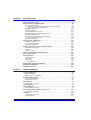


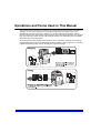

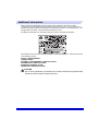


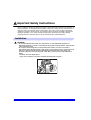

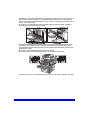
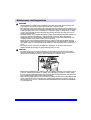
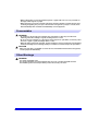

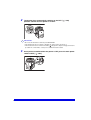
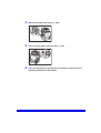

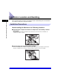

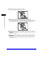
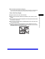
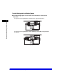
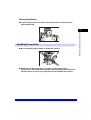

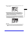
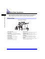
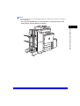
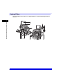
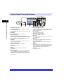
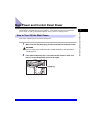
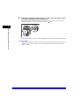

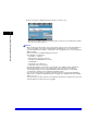

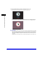
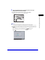
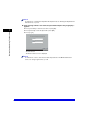
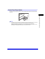

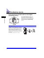


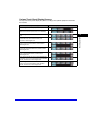
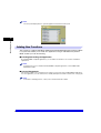


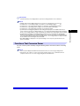
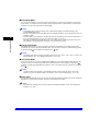

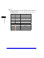

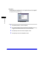


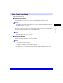
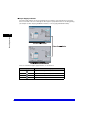

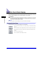
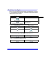
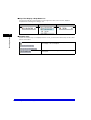
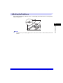
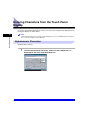

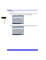
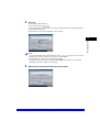
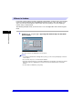
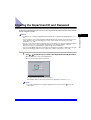
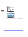
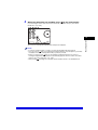

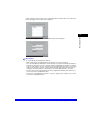
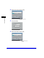


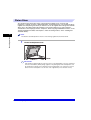
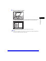


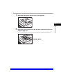
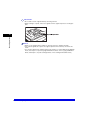

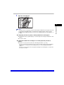
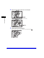
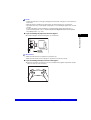
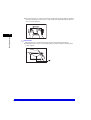
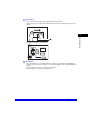

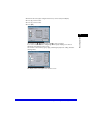
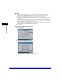

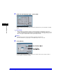

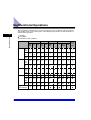


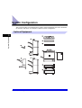
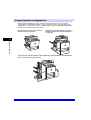
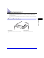
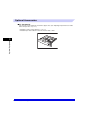
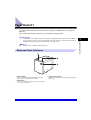
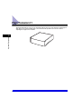
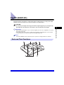

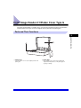
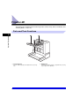
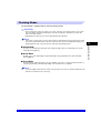
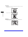

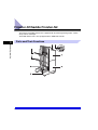
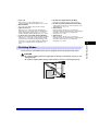
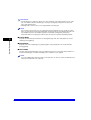
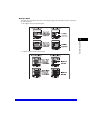
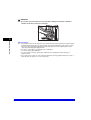
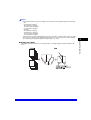
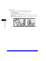

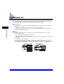
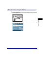
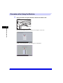


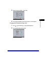


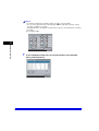
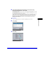
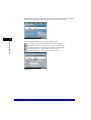
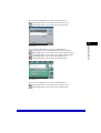

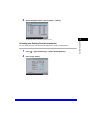
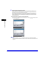

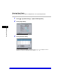

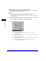
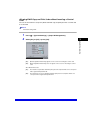
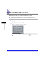
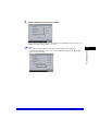
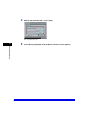

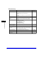
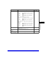
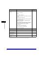
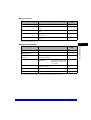
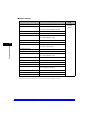
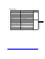
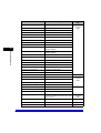
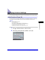

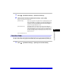
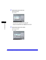
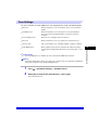
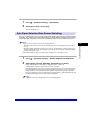
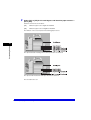
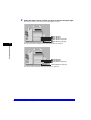
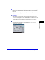

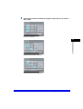


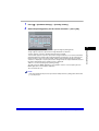

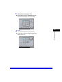
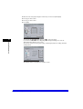
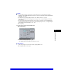

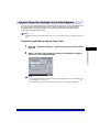

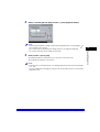
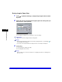
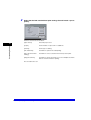
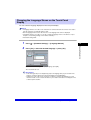
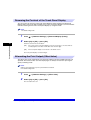

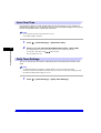
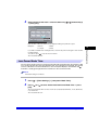
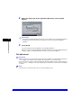
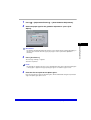


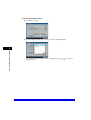
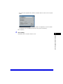
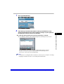
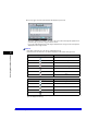
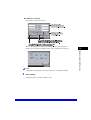
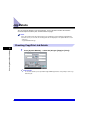

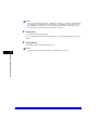
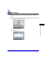


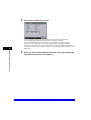
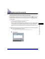
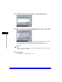

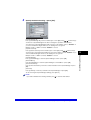
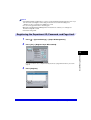
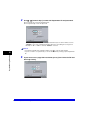
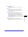

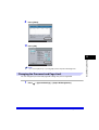


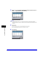
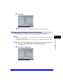
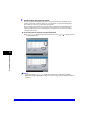
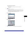
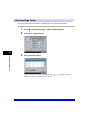
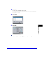

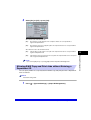
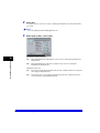

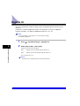
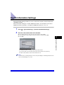

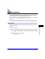
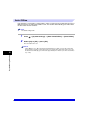
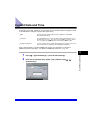
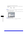


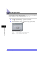
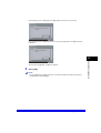
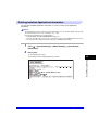
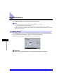
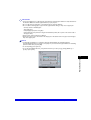
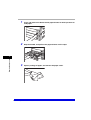


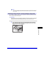
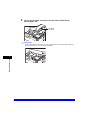

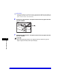
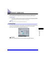
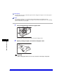
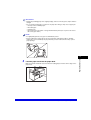
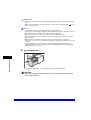
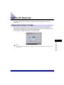
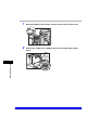
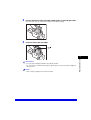
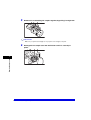
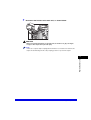
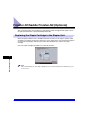
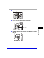
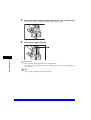
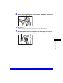
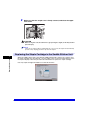
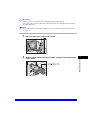

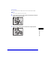
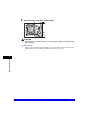
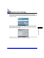

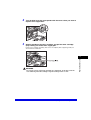
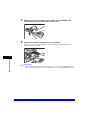
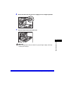

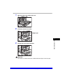
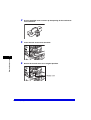
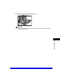
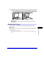
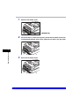

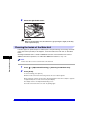


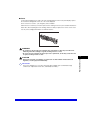


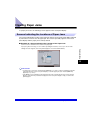
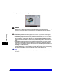

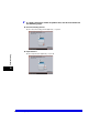

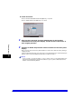
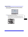
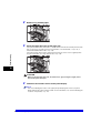
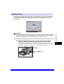
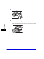
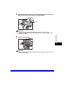
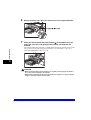
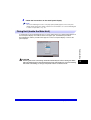
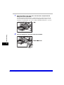
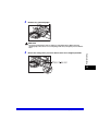
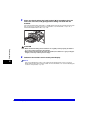
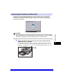
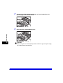

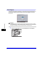
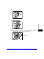


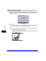

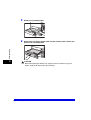
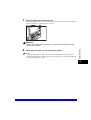

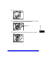


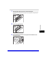
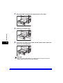
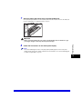
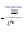
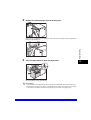
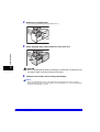

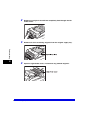
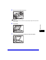
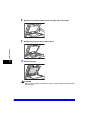
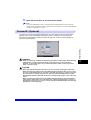
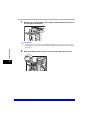

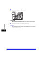
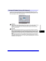
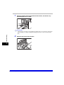
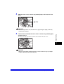
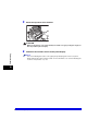
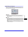
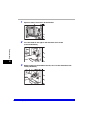
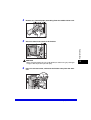


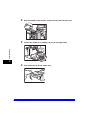
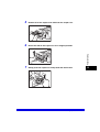
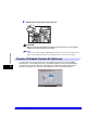
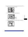
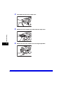
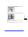

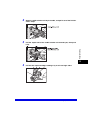
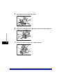
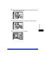


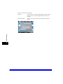
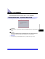
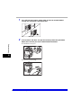

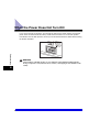

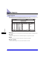
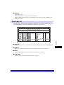

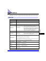

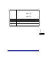


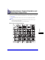
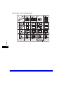
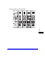

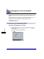
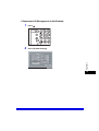
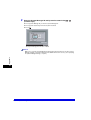

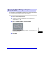


![[Impostazioni rete].](http://vs1.manualzilla.com/store/data/006126015_1-a8b230434cd1a1b69e1ac6b45a87b86d-150x150.png)