1
Network Intelligent Analog Fire Alarm and Audio System
Installation and Operation Manual
LT-894 Rev. 3
March 2013
FleX-NetTM Installation and Operation Manual
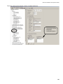
Table of Contents
Introduction .............................................................................................................................. 1
Additional Features.................................................................................................................. 3
Document Conventions........................................................................................................... 3
System Components ............................................................................................................... 6
Mechanical Installation and Dimensions ............................................................................... 14
Module Mounting Locations ................................................................................................... 22
Display and Adder Modules Mounting Locations................................................................. 24
Module Settings ....................................................................................................................... 27
Field Wiring............................................................................................................................... 45
Main Fire Alarm Module Terminal Connections.................................................................... 45
Analog Loop Wiring............................................................................................................... 48
FNC-2000 Fire Network Controller Module........................................................................... 54
FOM-2000-SP Fiber Optic Network Adder Module............................................................... 56
Detection Module (DM-1008A) Terminal Connections ......................................................... 57
Signal Module (SGM-1004A) Terminal Connections ............................................................ 58
Relay Module (RM-1008(A)) Terminal Connections ............................................................. 59
Polarity Reversal and City Tie Module (PR-300) Wiring ....................................................... 60
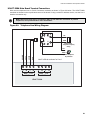
UDACT-300A Main Board Terminal Connections................................................................. 61
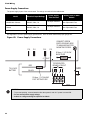
Power Supply Connections................................................................................................... 62
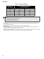
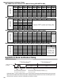
Wiring Tables and Information .............................................................................................. 63
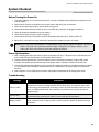
System Checkout ..................................................................................................................... 65
Indicators, Controls, and Operation....................................................................................... 66
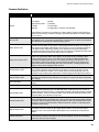
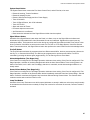
Common Indicators............................................................................................................... 67
Common Controls ................................................................................................................. 68
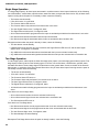
Single Stage Operation......................................................................................................... 70
Two Stage Operation ............................................................................................................ 70
Pre-Signal Operation ............................................................................................................ 71
Circuit Types ......................................................................................................................... 72
Configuration............................................................................................................................ 75
Configuration Backup, Query and Fast-Forward .................................................................. 75
OPEN Graphic Navigator Software Package........................................................................ 75
Ethernet Port......................................................................................................................... 75
Boolean Logic Engine ........................................................................................................... 75
uBoot Based BootLoader...................................................................................................... 75
Typical FleX-NetTM System Layouts with Audio .................................................................. 75
System Components for the Integrated Fire/Audio Cabinet ................................................ 77
Network Fire Alarm ............................................................................................................... 77
Network Controller Modules.................................................................................................. 77
Fiber Optics Module.............................................................................................................. 78
Adder Modules...................................................................................................................... 78
Auxiliary Modules.................................................................................................................. 78
Programmable Modules........................................................................................................ 78
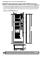
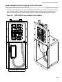
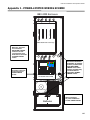
FleXNetTM Mass Notification System (BBX-FXMNS) Enclosure......................................... 79
Integrated Fire/Audio Cabinet Mechanical Installation ........................................................ 83
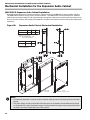
Mechanical Installation for the Expansion Audio Cabinet ................................................... 85
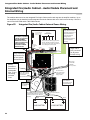
Integrated Fire/Audio Cabinet - Audio Module Placement and Internal Wiring ................. 87
Integrated Fire Alarm Connection .......................................................................................... 88
Battery Power ....................................................................................................................... 88
Transformer Power ............................................................................................................... 88
QBB-5001 Expansion Audio Cabinet Module Placement..................................................... 89
QPS-5000N Power Supply Connection ................................................................................ 90
Installing and Removing Amplifiers ....................................................................................... 90
Multiple QBB-5001 Cabinet Connections .............................................................................. 91
i
Table of Contents
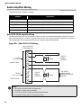
Audio Network Card and Telephone Network Card .............................................................
Audio Amplifier Wiring ...........................................................................................................
QAA-5230-70/25 Amplifier Wiring ........................................................................................
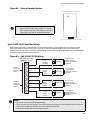
QAA-5230S-70/25 Amplifier Wiring......................................................................................
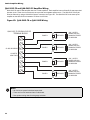
QAA-5415-70 and QAA-5415-25 Amplifier Wiring ...............................................................
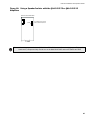
QAA-5160-70/25 ..................................................................................................................
Backup Amplifier ..................................................................................................................
Displays & Controls ................................................................................................................
Setup ........................................................................................................................................
QBB-5001 Amplifier Installation ...........................................................................................
Before Turning the Power "ON"... ........................................................................................
Audio Configuration................................................................................................................
Lobby Enclosures ...................................................................................................................
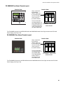
ANC-5000 Audio Network Controller Module .......................................................................
ANC-5000 Wiring .....................................................................................................................
QMP-5101NV Vertical Paging Module ...................................................................................
Paging Modules.......................................................................................................................
QMP-5101N Network Master Paging Control Module .........................................................
QMP-5101N Network Paging Wiring ......................................................................................
Paging Operation ....................................................................................................................
TNC-5000 Telephone Network Controller Module................................................................
TNC-5000 Telephone Wiring...................................................................................................
QMT-5302NV Vertical Master Telephone...............................................................................
QMT-5302N Master Firefighters’ Telephone .........................................................................
QMT-5302N Connections........................................................................................................
QAZT-5302/DS Network Firefighters’ Telephone Selector Panel........................................
Telephone Operation ..............................................................................................................
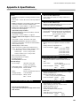
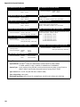
Appendix A: Specifications....................................................................................................
Compliance ..........................................................................................................................
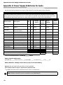
ULI/ULC Integrated Fire Alarm and Audio Panel Specifications ..........................................
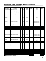
Appendix B: Power Supply and Battery Calculations .........................................................
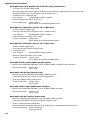
RAXN-LCD/RAXN-LCDG:....................................................................................................
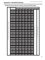
Appendix C: DIP Switch Settings ..........................................................................................
ANC-5000 Board with Ethernet Port, Address Setting (DIP SWITCH SW1) .......................
ANC-5000 Board without Ethernet Port, Address Setting (DIP SWITCH SW1) ..................
ACN-792M Loop Adder Module (CPU) Address Setting (DIP SWITCH SW1) ....................
RAXN-LCD/RAXN-LCDG Remote Annunciator Address Setting (DIP SWITCH SW1) .......
Appendix D: Alarm Verification Timing.................................................................................
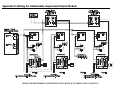
Appendix E: Wiring for Addressable Supervised Output Module ......................................
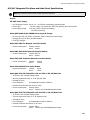
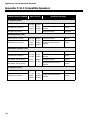
Appendix F: ULC Compatible Speakers................................................................................
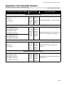
Appendix G: ULI Compatible Speakers.................................................................................
Appendix H: Power Supply & Batteries for Audio ...............................................................
Appendix I - POWER-LIMITED WIRING SCHEME.................................................................
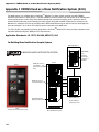
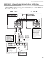
Appendix J FXMNS Used as a Mass Notification System (ACU).......................................
Warranty & Warning Information ...........................................................................................
ii
92
93
93
94
95
99
101
102
103
103
103
103
104
105
106
108
109
109
111
112
114
118
120
121
122
123
125
126
127
129
130
131
132
133
133
133
133
133
134
135
136
137
138
139
144
FleX-NetTM Installation and Operation Manual
Introduction
About the FleX-NetTM Network Fire and Emergency Communication System
Mircom’s FleX-NetTM Intelligent Fire Alarm and Audio Network offers modular components for network systems
providing a wide variety of applications. Designed for peer to peer network communications, using industrial
standard ARCnet protocol. FleX-NetTM allows for a maximum of 63 nodes (where a node can be a control center or
a floor panel) while providing reliability and flexibility.
FleX-NetTM is based on the proven and reliable FX-2000 Fire Alarm Control Panel platform. Each base panel
consists of one intelligent analog loop controller capable of supporting 99 analog sensors and 99 addressable
modules. In addition, the base panel also consists of 4 Class A/B (Style Z/Y) Indicating Circuits (NACs) rated at 1.7
amperes each and a large 4 x 20 back-lit alphanumeric LCD display.
The FleX-NetTM configuration allows the FleX-NetTM Fire Alarm Control Panels to be connected to a Mircom
network which provides additional input circuits, visual zones, programmable notification appliance circuits and
relays. In addition, a FleX-NetTM Integrated Fire and Audio panel can be used to provide a fully distributed audio
and/or integrated telephone system.
Mircom's FleX-NetTM Network system also provides zoned emergency multi-channel audio providing emergency
paging and fire evacuation, and an optional firefighters’ telephone communication to and from CACF (Central Alarm
and Control Facilities) location to all remote telephone handsets. The system consists of Integrated Fire and Audio
Network Panel or FX-MNS nodes. Each Integrated Fire and Audio Network Panel or FX-MNS contains an audio
portion which consists of a QMB-5000N motherboard and card cage which holds an ANC-5000 Audio Network
Card, a TNC-5000 Telephone Network Card and up to 4 amplifiers, a fire alarm portion FX-2000ND Main Chassis, a
PS-2040 power supply and batteries. The QBB-5001/R expansion audio cabinet (connected to a Integrated Fire
and Audio Network Panel or FX-MNS node) contains a card cage motherboard which holds up to 7 amplifiers, has
an audio power supply, battery charger and batteries all housed in an audio backbox enclosure.
For communication and annunciation there is a microphone for paging, a paging selector panel, firefighters’
telephone and associated selector panels all housed in a central enclosure (CACF). The master paging and
telephone modules are intended for installation in a CACF.
Note that the paging microphone and firefighters’ telephone may be used together or independently, connected to a
FleX-NetTM Network Central Alarm and Control Facility (CACF).
Overall Features
•
•
•
•
•
•
•
•
•
•
•
Large System Capacity and Modular Design.
Provides peer-to-peer network communications
Supports up to 63 nodes (including lobby panel).
Supports copper and/or fiber optic network cable.
Each Analog Loop is capable of supporting 99 Digital or Analog Sensors and 99 Addressable Modules which
can be wired as Class A (Style 6 or 7) or Class B (Style 4).
12 Ampere Power Supply.
Four Class A/B (Style Z/Y) NACs rated at 1.7 Amperes each, which can be configured as Audible or Visual
(silenceable or non-silenceable circuits). Audibles may be steady, Temporal Code, California Code, or March
Time.
Indicating circuits (NACs) may be configured to provide additional auxiliary power or resettable auxiliary power.
NAC expansion using the INX-10A, INX-10ADS or INX-10AC.
Fault isolators are present on all in-panel addressable loops.
Configurable Signal Silence Inhibit, Auto Signal Silence, Two-Stage Operation, One-Man Walk Test.
Outputs for 4 Wire resettable Smoke Power Supply, Auxiliary Power Supply, and an interface to the Mircom
RTI-1 Remote Trouble Indicator.
1
Introduction
• RS-485 Interface for Remote Annunciators. Remote Annunciators do not occupy a node on the network. Up to
seven annunciators can be connected per node.
• Three Level Password Protection with field settable definition which enables the installer to determine what
functions are accessible for each level of password
• Four Queues for Alarm, Supervisory, Trouble, and Monitor, with LED indicators and selector keys.
• Auxiliary Form-C Relay Contacts for Common Alarm, Common Supervisory, and Common Trouble.
• RS-232 Port for remote system printer or “CRT terminal”.
• Two Event History Logs; one for Alarm related events and one for all events.
• Large 4 line by 20 character alphanumeric, back-lit LCD Display with user-friendly menu system.
• Common Controls and Indicators for System Reset, Lamp Test, Fire Drill, Signal Silence, General Alarm,
Acknowledge, AC On, Pre-Alarm, and Ground Fault.
• Two Spare configurable switches and LED Indicators.
• 16 Zone configurable LED (bi-coloured) Annunciator with slide-in labels for Zone Description.
• Provides drift compensation for ionization and photoelectric smoke detectors
• Provides Signal Coding of signal circuits for easy alarm identification (code consists of 1 to 4 digits, each digit
consisting of 1-15 pulses on the signal)
• Selection for Canadian (ULC) or USA (ULI) requirements for Smoke Sensor sensitivity.
• Extensive transient protection.
• Surface Mountable Enclosures with removable doors for easy installation and service. Flush Trims Available.
• Removable Terminal Blocks for easy wiring and service.
• Quad Loop Adder module ALCN-792M for expanding addressable loops by 2; with daughter board ALCN-792D
expanding addressable loops by a total of 4.
Overall Audio Features:
• Supervises signal circuits while in use.
• Control of fire management operations (e.g. all-call paging and total evacuation signalling).
• Indication of all required fault conditions.
• Microprocessor-based operations with hardware and software watchdog timer to ensure reliable system
operation.
• Supervised tone generators.
• Up to 100 audio zones per node, 1575 audio amplifiers per Network system.
• Up to 5 (analog) firefighters’ telephone zones per node and 315 (analog) telephone zones per Network system.
• 99 addressable telephone zones per loop, maximum of 29 addressable telephone loops per node, maximum of
144 addressable telephone zones per system.
• Easy configuration process.
• Operates from 24 VDC backup batteries in the event of a power failure.
• Removable terminal blocks for ease of installation and maintenance.
• Speaker circuits integrated with amplifier circuits.
• Maximum of 180 Watts per Integrated Fire and Audio Cabinet (BBX-2000) and FX-MNS.
• Maximum of 360 Watts per QBB-5001/R expansion cabinet and 1260 Watts of total power per Integrated Fire
and Audio Panel (BBX-2000) or FX-MNS node with maximum expansion [180W +360W(3)=1260W].
• Optional redundant backup amplifier per node.
2
FleX-NetTM Installation and Operation Manual
Additional Features
Blackfin based Quad Loop Adder module ALCN-792M. The ALCN-792M is a 2 loop addressable adder module
with provision to connect a daughter board ALCN-792D which contains an additional 2 addressable loops for a total
of four addressable loops.
There are two additional main fire alarm panel displays:
DSPL-420 8 line LCD display narrow board
DSPL-2440 9 event, 24 line graphical display narrow board
The BBX-FXMNS enclosure is for the Integrated Fire and Audio consisting of a backbox, door and middle chassis.
Part of this enclosure is the vertical mount telephone QMT-5302NV and the vertical mount paging microphone
QMP-5101NV.
The ANC-5000 Audio Network Controller module includes ARCnet and an ethernet port. ARCnet reduces the wiring
for audio and telephone to the ARCnet only or fiber optics (if used).
The QBC-5000N charger provides a dual voltage transformer for audio.
The RAXN-LCDG is a graphical display remote annunciator.
The FleXNetTM is compatible with Coptir, Pinnacle, Acclimate and 4-20mA devices.
Configuration options are provided for grouping inputs.
Panel supports previous, current and next configuration. Configuration automatically reverts back to previous or
moves to future configuration through front-panel menu.
OPEN Graphic Navigator Software Package allows 3D graphic display of premises and devices. Use the
ethernet port on the main board to connect to OPEN graphics software.
Boolean logic functions are now available within the configuration software.
uBoot Based BootLoader program (inherent in the configuration) provides leading technology that allows a choice
of multiple configuration files or firmware revisions to support site-specific requirements.
The FleXBootTM shell offers UNIX style commands for directory listing, log download, diagnostic probing and
system tuning and optimization.
Document Conventions
Circuits and Zones
The term circuits refers to an actual electrical interface, initiating (detection), indicating (signal), or relay.
The term zone is a logical concept for a fire alarm protected area, and will consist of at least one circuit.
Often the terms zone and circuit are used interchangeably, but in this manual the term circuit is used.
On the FleX-NetTM, circuits can be hardwired inputs and outputs or addressable inputs and outputs. Both hardwired
inputs and outputs, and addressable inputs and outputs may be grouped together to form logical zones.
Wiring Styles
Initiating circuits are configured by default as Class B (Style B). They may be configured as Class A (Style D) as
described in System Configuration. This operation uses odd and even pairs of two-wire Class B (Style B) circuits to
make one four-wire Class A (Style D) circuit, thus cutting in half the number of available initiating circuits.
Indicating circuits (NACs) may be individually wired as Class A (Style Z) or Class B (Style Y) without affecting the
number of circuits available.
Addressable Loops may be configured system wide as Class B (Style 4) or Class A (Style 6). With the addition of
isolators, a Class A (Style 6) will become a Class A (Style 7).
3
4
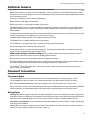
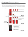
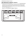
Node 5
Node 4
FX-2009-12N in a BB-5008R
CACF
Node 1
Twisted Pair Wiring
Class A wiring
FX-2017-12N in a BBX-1072RA
RAXN-LCD in a BB-1001R
RS-485
FX-2003-12N in a BBX-1024R
RAXN-LCD in a BB-1001R
RS-485
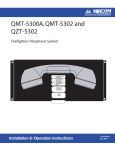
Typical FleX-Net TM Wiring Without Audio
Node 2
RAXN-LCD in a BB-1001R
RS-485
FX-2017-12N in a BBX-1072RA
Node 3
FX-2003-12N in a BBX-1024R
Document Conventions
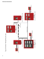
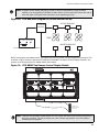
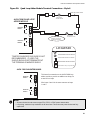
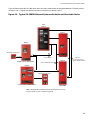
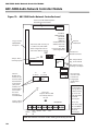
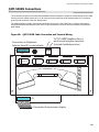
ARCnet
Internal RS-485
Telephone Audio
Paging Audio
and/or
Signal
AGD-048
Graphic Driver
IPS-2424
Zone Bypass
-2000
Relays
RM-1008A
RAXN-LCD
Annunciator
FX-2000N
Main Board
AGD-048
IPS-2424
RAX-1048TZ
Display Adder
RAX-1048TZ
Fan Damper Controller
FDX-008
Conventional Devices
PTR-2000-1
FDX-008
Fan Damper Controller
Inputs
1004A DM-1008A
FOM-2000-SP Fibre Optic
Network Module
Addressable Devices
Addressable Devices
Loop 2
FNC-2000 Network
Controller Module
ALCN-792D Analog Loop
Network Module
UDACT-300A Digital
Communicator Module
Phone Line 1
Phone Line 2
ANC-5000 & TNC-5000 in Audio Card Cage
Alert 1
Paging Audio
Handsets
Speakers
Five Telephone
Circuits per TNC-5000
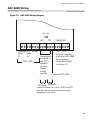
Node1
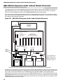
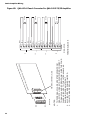
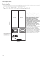
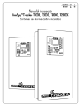
Typical FleX-Net TM Wiring With Audio
Node 3 - Floor Panel
RAXN-LCD in
BB-1001R
Node 2 - Floor Panel
Five Telephone
RAXN-LCD in
BB-1001R
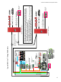
NOTES:
(1) The main board has two conventional loops, one SLC loop and 4 Class B (Style Y) NAC circuits.
(2) The main FX-2000N supports a maximum of 12 frames (a frame is a measure of display capacity).
(3) Each FX-2000N supports a maximum of seven ALCN-792M Quad Addressable Loop Adder Module
plus ALCN-792D for a total of 29 loops per FX-2000N.
(4) The system supports a maximum of 7 annunciators per node.
(5) Annunciators RAXN-LCD and RAXN-LCDG can support a maximum of 41 frames each, which include
IPS-2424, FDX-008, AGD-048, RAX-1048TZ and QAZT-5302.
(6) If high speed digitized audio is used only the ARCnet or Fiber Optic wiring is required between nodes.
1 twisted pair or 2 fibre optic cables for
ARCnet Network , Fire Control, Paging
Audio and Telephone
Five Telephone
FleX-NetTM Installation and Operation Manual
5
Mircom
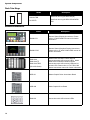
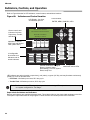
System Components
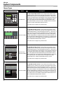
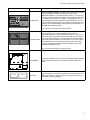
Chassis Types
Model
Mircom FX-2000
Fire Alarm Control Panel
Normal Condition
December 31, 1999
MENU
ENTER
CANCEL
SIGNAL
SILENCE
FIRE
DRILL
GENERAL
ALARM
SYSTEM
RESET
INFO
A.C. ON
MONITOR
QUEUE
TROUBLE
QUEUE
SUPV.
QUEUE
ALARM
QUEUE
PRE-ALARM
GND FAULT
2nd STAGE
AUTO CANCEL
FX-2003-12N
LAMP
TEST
Description
12 Amp Compact Main Chassis. This compact main chassis comes
complete with one Analog Loop Controller (99 Analog Sensors and 99
Addressable Modules), 4 Class A/B (Style Z/Y) NACs (1.7 Amp each), a
4 line by 20 character back-lit LCD display, 16 zone LED annunciator and
a 12 ampere power supply which charges 17-65 AH batteries. The FX2003-12N supports the FNC-2000 Network Controller Module and 2
other adder modules. This unit mounts in the BBX-1024 black backbox/
white door or BBX-1024R black backbox/red door.
A.C. LINE
CIRCUIT
BREAKER
This model does not support any network audio.
FX-2017-12NDS
12 Amp Mid-Size Main Chassis. This mid-size main chassis comes
complete with one Analog Loop Controller (99 Analog Sensors and 99
Addressable Modules), 4 Class A/B (Style Z/Y) NACs (1.7 Amp each), a
DSPL-420 4 line by 20 character LCD display and a 12 ampere power
supply which charges 17-65 AH batteries. The FX-2017-12N supports
the FNC-2000 Network Controller Module and two adder modules over
the main board plus additional space in the chassis for 14 adder boards.
This chassis mounts in the BBX-1072A/DS black backbox/white door or
BBX-1072RA/ARDS black backbox/ red door.
This model does not support any network audio.
ZONE
BYPASS
#1
ZONE
BYPASS
#5
ZONE
BYPASS
#9
ZONE
BYPASS
#13
ZONE
BYPASS
#17
ZONE
BYPASS
#21
ZONE
BYPASS
#1
ZONE
BYPASS
#5
ZONE
BYPASS
#9
ZONE
BYPASS
#13
ZONE
BYPASS
#17
ZONE
BYPASS
#21
ZONE
BYPASS
#2
ZONE
BYPASS
#6
ZONE
BYPASS
#10
ZONE
BYPASS
#14
ZONE
BYPASS
#18
ZONE
BYPASS
#22
ZONE
BYPASS
#2
ZONE
BYPASS
#6
ZONE
BYPASS
#10
ZONE
BYPASS
#14
ZONE
BYPASS
#18
ZONE
BYPASS
#22
ZONE
BYPASS
#3
ZONE
BYPASS
#7
ZONE
BYPASS
#11
ZONE
BYPASS
#15
ZONE
BYPASS
#19
ZONE
BYPASS
#23
ZONE
BYPASS
#3
ZONE
BYPASS
#7
ZONE
BYPASS
#11
ZONE
BYPASS
#15
ZONE
BYPASS
#19
ZONE
BYPASS
#23
ZONE
BYPASS
#4
ZONE
BYPASS
#8
ZONE
BYPASS
#12
ZONE
BYPASS
#16
ZONE
BYPASS
#20
ZONE
BYPASS
#24
ZONE
BYPASS
#4
ZONE
BYPASS
#8
ZONE
BYPASS
#12
ZONE
BYPASS
#16
ZONE
BYPASS
#20
ZONE
BYPASS
#24
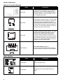
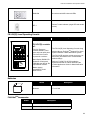
Mircom FX-2000
Fire Alarm Control Panel
Normal Condition
December 31, 1999
FX-2017-12N
FX-2017-12NDS
MENU
ENTER
CANCEL
INFO
ALARM
QUEUE
A.C. ON
SUPV.
QUEUE
TROUBLE
QUEUE
PRE-ALARM
MONITOR
QUEUE
SIGNAL
SILENCE
FIRE
DRILL
GENERAL
ALARM
SYSTEM
RESET
2nd STAGE
AUTO CANCEL
LAMP
TEST
GND FAULT
12 Amp Mid-Size Main Chassis. This mid-size main chassis comes
complete with one Analog Loop Controller (99 Analog Sensors and 99
Addressable Modules), 4 Class A/B (Style Z/Y) NACs (1.7 Amp each), a
4 line by 20 character back-lit LCD display, 16 zone LED annunciator and
a 12 ampere power supply which charges 17-65 AH batteries. The FX2017-12N supports the FNC-2000 Network Controller Module and two
adder modules over the main board plus additional space in the chassis
for 14 adder boards. This chassis mounts in the BBX-1072A black
backbox/white door or BBX-1072RA black backbox/ red door.
A.C. LINE
CIRCUIT
BREAKER
This model does not support any network audio.
ZONE
BYPASS
#1
ZONE
BYPASS
#5
ZONE
BYPASS
#9
ZONE
BYPASS
#13
ZONE
BYPASS
#17
ZONE
BYPASS
#21
ZONE
BYPASS
#1
ZONE
BYPASS
#5
ZONE
BYPASS
#9
ZONE
BYPASS
#13
ZONE
BYPASS
#17
ZONE
BYPASS
#21
ZONE
BYPASS
#2
ZONE
BYPASS
#6
ZONE
BYPASS
#10
ZONE
BYPASS
#14
ZONE
BYPASS
#18
ZONE
BYPASS
#22
ZONE
BYPASS
#2
ZONE
BYPASS
#6
ZONE
BYPASS
#10
ZONE
BYPASS
#14
ZONE
BYPASS
#18
ZONE
BYPASS
#22
ZONE
BYPASS
#3
ZONE
BYPASS
#7
ZONE
BYPASS
#11
ZONE
BYPASS
#15
ZONE
BYPASS
#19
ZONE
BYPASS
#23
ZONE
BYPASS
#3
ZONE
BYPASS
#7
ZONE
BYPASS
#11
ZONE
BYPASS
#15
ZONE
BYPASS
#19
ZONE
BYPASS
#23
ZONE
BYPASS
#4
ZONE
BYPASS
#8
ZONE
BYPASS
#12
ZONE
BYPASS
#16
ZONE
BYPASS
#20
ZONE
BYPASS
#24
ZONE
BYPASS
#4
ZONE
BYPASS
#8
ZONE
BYPASS
#12
ZONE
BYPASS
#16
ZONE
BYPASS
#20
ZONE
BYPASS
#24
FX-2017-12NDS
Mircom FX-2000
Fire Alarm Control Panel
Normal Condition
December 31, 1999
MENU
ENTER
CANCEL
INFO
ALARM
QUEUE
A.C. ON
SUPV.
QUEUE
PRE-ALARM
TROUBLE
QUEUE
MONITOR
QUEUE
SIGNAL
SILENCE
FIRE
DRILL
GENERAL
ALARM
SYSTEM
RESET
2nd STAGE
AUTO CANCEL
LAMP
TEST
GND FAULT
12 Amp Mid-Size Main Chassis. This mid-size main chassis comes
complete with one Analog Loop Controller (99 Analog Sensors and 99
Addressable Modules), 4 Class A/B (Style Z/Y) NACs (1.7 Amp each), a
DSPL-420 4 line by 20 character LCD display, and a 12 ampere power
supply which charges 17-65 AH batteries. The FX-2017-12NDS supports
the FNC-2000 Network Controller Module and two adder modules over
the main board plus additional space in the chassis for 14 adder boards.
This chassis mounts in the BBX-1072A/DS black backbox/white door or
BBX-1072RA/ARDS black backbox/ red door.
A.C. LINE
CIRCUIT
BREAKER
This model does not support any network audio.
6
FleX-NetTM Installation and Operation Manual
Mircom FX-2000
Fire Alarm Control Panel
Normal Condition
December 31, 1999
MENU
ENTER
CANCEL
INFO
ALARM
QUEUE
A.C. ON
SUPV.
QUEUE
TROUBLE
QUEUE
PRE-ALARM
MONITOR
QUEUE
SIGNAL
SILENCE
FIRE
DRILL
GENERAL
ALARM
SYSTEM
RESET
2nd STAGE
AUTO CANCEL
LAMP
TEST
GND FAULT
ZONE
BYPASS
#1
ZONE
BYPASS
#5
ZONE
BYPASS
#9
ZONE
BYPASS
#13
ZONE
BYPASS
#17
ZONE
BYPASS
#21
ZONE
BYPASS
#2
ZONE
BYPASS
#6
ZONE
BYPASS
#10
ZONE
BYPASS
#14
ZONE
BYPASS
#18
ZONE
BYPASS
#22
ZONE
BYPASS
#3
ZONE
BYPASS
#7
ZONE
BYPASS
#11
ZONE
BYPASS
#15
ZONE
BYPASS
#19
ZONE
BYPASS
#23
ZONE
BYPASS
#4
ZONE
BYPASS
#8
ZONE
BYPASS
#12
ZONE
BYPASS
#16
ZONE
BYPASS
#20
ZONE
BYPASS
#24
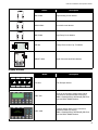
FX-2009-12N
12 Amp Large Main Chassis. This large main chassis comes complete
with one Analog Loop Controller (99 Analog Sensors and 99
Addressable Modules), 4 Class A/B (Style Z/Y) NACs (1.7 Amp each), a
4 line by 20 character back-lit LCD display, 16 zone LED annunciator and
a 12 ampere power supply which charges 17-65 AH batteries. The FX2009-12N supports the FNC-2000 Network Controller Module over the
main board plus additional space in the chassis for 8 adder boards. This
chassis mounts in the BB-5008 or BB-5014 black backbox/black door or
BB-5008R black backbox/red door.
This is model does not support any network audio.
FX-2009-12NDS
12 Amp Large Main Chassis. This large main chassis comes complete
with one Analog Loop Controller (99 Analog Sensors and 99
Addressable Modules), 4 Class A/B (Style Z/Y) NACs (1.7 Amp each), a
DSPL-420 4 line by 20 character back-lit LCD display, and a 12 ampere
power supply which charges 17-65 AH batteries. The FX-2009-12NDS
supports the FNC-2000 Network Controller Module over the main board
plus additional space in the chassis for 8 adder boards. This chassis
mounts in the BB-5008 or BB-5014 black backbox/black door or BB5008R black backbox/red door.
This is model does not support any network audio.
Cutout to mount
display module
Cutout to mount
display module
FX-2000MNS
Consists of a backplate which is mounted into the BBX-FXMNS backbox
and a FX-2000N Fire Alarm Control board and a battery disconnect
board.
ECX-0012
Expander Chassis to use with the FX-2009-12N. It provides space for 12
adder modules and two display modules. This chassis mounts into the
BB-5008(R) or BB-5014 backbox.
7
System Components
Network Controller Modules
Model
Description
FNC-2000
Provides network capability for the FX-2000N Fire
Alarm panel. One module is required per one
network node panel. The FNC-2000 Fire Network
Controller module is mounted in position 2 over
the FX-2000N main board.
ANC-5000
Audio Network Controller module. The ANC-5000
Audio Network Controller module is mounted over
a metal plate (which is packaged with the FX2009-12N) and then the plate is mounted in a BB5008 or BB-5014 backbox in positions marked 4 to
9 inclusive. The recommended plate mounting is
sideways with LEDs across the top.
TNC-5000
Telephone Network Controller module. The TNC5000 Telephone Network Controller module is
mounted over the ANC-5000 Audio Network
Controller module and both are mounted on a
metal plate and then the plate is mounted in a BB5008 or BB-5014 backbox in positions marked 4 to
9 inclusive. The recommended plate mounting is
sideways with LEDs across the top.
FOM-2000-SP
Fiber Optics Module (Optional)
Connects to the FNC-2000 Fire Alarm Network
Controller Module and allows fiber optics cabling.
0
*0
0!-03)NTERFACE
*0
*7
*0
*7
0
*7
*7
0.ETWORK23
023$EBUG
0(?3PEED!UDIO
023
*7
*7
*7
*7 *7
- - + +- - ++
- - + +- + S - + S + -
RX2
RX1
TX2
TX1
P1
Adder Modules
Model
+
-
+
B
A
LOOP (3)
P1
8
-
S S
COM (-)
To Main Board
Connector P6
+
-
+
Description
ALCN-792M
Quad Loop Adder board.
ALCN-792D
Daughter board for ALCN-792M Quad Loop
Adder
-
B
A
LOOP (4)
FleX-NetTM Installation and Operation Manual
Model
+ | -
POLARITY POLARITY
REVERSAL REVERSAL
SUPV
ALARM
P2
DM-1008A
Eight Initiating Circuit Module
SGM-1004A
Four NAC circuit Module
RM-1008A
Eight Relay Circuit Module
PR-300
Polarity Reversal and City Tie Module
UDACT-300A
Digital Communicator/Dialer Module
CITY
TIE
+ | -
P1
Description
+ | -
JW4
Display Modules
Model
OFF AUTO ON
TROUBLE
OFF AUTO ON
TROUBLE
OFF
OFF AUTO
AUTO ON
ON TROUBLE
TROUBLE
OFF AUTO ON
TROUBLE
OFF AUTO ON
TROUBLE
OFF AUTO ON
TROUBLE
OFF AUTO ON
TROUBLE
OFF AUTO ON
TROUBLE
Flexnet
System Normal
Description
FDX-008
Fan Damper Module
DSPL-420
4 line by 20 charactor display which can be
mounted into backboxes BBX-1072A(RA),
BBX-1072ADS(ARDS), BB-5008(R), BB-5014
and the BBX-FXMNS Backbox.
DSPL-2440
Graphic display which can be mounted in
backboxes BBX-1072A(RA),
BBX-1072ADS(ARDS), BB-5008(R), BB-5014
and the BBX-FXMNS Backbox
9
System Components
Model
ZONE
BYPASS
#1
ZONE
BYPASS
#5
ZONE
BYPASS
#9
ZONE
BYPASS
#13
ZONE
BYPASS
#17
ZONE
BYPASS
#21
ZONE
BYPASS
#2
ZONE
BYPASS
#6
ZONE
BYPASS
#10
ZONE
BYPASS
#14
ZONE
BYPASS
#18
ZONE
BYPASS
#22
ZONE
BYPASS
#3
ZONE
BYPASS
#7
ZONE
BYPASS
#11
ZONE
BYPASS
#15
ZONE
BYPASS
#19
ZONE
BYPASS
#23
ZONE
BYPASS
#8
ZONE
BYPASS
#12
ZONE
BYPASS
#16
ZONE
BYPASS
#20
ZONE
BYPASS
#24
ZONE
BYPASS
#4
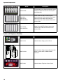
IPS-2424/DS
RAM-1032
RAM-1032TZ
RAM-1032TZDS
RAX-1048TZ
RAX-1048TZDS
Description
Programmable Input Switches Module (mounts
with the FX-2009-12N and can also be part of
the RAXN-LCD)
Model RAM-1032 Main Chassis Remote
Annunciator with 32 Bi-coloured LEDs. Model
RAM-1032TZ/DS Main Chassis Remote
Annunciator with 16 Bi-coloured LEDs and 32
trouble LEDs.
Model RAX-1048TZ/DS Adder Annunciator
Chassis with 48 Bi-coloured LEDs and 48
trouble LEDs.
Audio and Telephone Modules
WARDEN
PAGE
PAGE TO
EVAC
ALL CALL
PAGE TO
ALERT
COMMON
TROUBLE
PRE-TONE
ACTIVE
AMPLIFIER
TROUBLE
MIC
TROUBLE
PAGE
CANCEL
A.C. ON
PAGE
READY
LAMP
TEST
PAGE TO
EVAC
ALL CALL
PAGE TO
ALERT
PRE-TONE
ACTIVE
AMPLIFIER
TROUBLE
MICROPHONE
Description
ALL CALL
MINUS
WARDEN
PAGE
MIC
ACTIVE
Model
QMP-5101N
Network Master Paging Control Panel
QMP-5101NV
Network Master Paging Control Panel (Vertical
Mount) mounts within the BBX-FXMNS
enclosure.
QMT-5302N
Network Master Telephone Control Panel
A.C. ON
PAGE
READY
ALL-CALL
MINUS
TROUBLE
PAGE
CANCEL
10
LAMP
TEST
FleX-NetTM Installation and Operation Manual
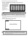
CALL CONTROL
ACTIVE
DESELECT ALL
TROUBLE
Model
INCOMING CALL
Description
CALL CONTROL
Telephone
#1
Telephone
#5
Telephone
#9
Telephone
#13
Telephone
#17
Telephone
#2
Telephone
#6
Telephone
#10
Telephone
#14
Telephone
#18
Telephone
#22
Telephone
#3
Telephone
#7
Telephone
#11
Telephone
#15
Telephone
#19
Telephone
#23
Telephone
#4
Telephone
#8
Telephone
#12
Telephone
#16
Telephone
#20
Telephone
#24
QMT-5302NV
Network Master Telephone Control Panel
(Vertical Mount) mounts within the BBX-FXMNS
enclosure.
QAZT-5302/DS
Zoned Paging and Telephone Selector Panel
Telephone
#21
Booster Power Supply
Model
Addressable Booster Power Supply mounts to
backboxes BB-5014 and BBX-FXMNS. Same
unit as the INX-10A and INX-10ADS, except
this model comes with a chassis for mounting.
Refer to LT-899 manual for more detailed
instructions.
INX-10A Board
Transformer
Battery
Battery
Description
INX-10AC
Enclosures
Model
B
Description
BBX-1024 white door black backbox
(add suffix “R” for red door/black backbox)
Enclosure 26”H x 14.5”W x 4.5”D
BBX-1024DS white door black backox
(add suffix “R” for red door/black backbox)
Enclosure 27.5”H x 16.5”W x 5.5”D
BBX-1072A white door black backbox
(or BBX-1072RA for door/black backbox)
Enclosure 32.5”H x 25”W x 6.5”D
BBX-1072ADS white door black backbox
(or BBX-1072RADS for door/black backbox)
Enclosure 34”H x 26.5”W x 7.7”D
BB-5008 black door and backbox
(add suffix “R” for red door/black backbox)
Backbox 36”H x 30”W x 7”D
BB-5014 black door and backbox
Backbox 60”H x 30”W x 7”D
BBX-FXMNS Enclosure with Door Assembly
(add suffix “R” for red door/black backbox)
Backbox 61.5”H x 22”W x 9”D
11
System Components
Flush Trim Rings
Model
FA-UNIV-TRB
FA-1072TR
Description
Black flush trim ring for BBX-1024(R)
Black flush trim ring for BBX-1072A/RA/DS/
RDS.
Remote Annunciators
Model
Mircom FX-2000N
Fire Control System
- System Normal Jan 01, 2011 12:21 AM
ENTER
CANCEL
INFO
RAXN-LCD
Remote Shared Display Annunciator. Please
refer to LT-895 RAXN-LCD manual for further
information.
RAXN-LCDG
Remote Shared Graphical Display Annunciator.
Please refer to LT-6033 RAXN-LCDG manual for
further information.
A.C.
ON
ALARM
QUEUE
SUPV.
QUEUE
TROUBLE
QUEUE
MONITOR
QUEUE
PREALARM
GROUND
FAULT
SIGNAL
SILENCE
GENERAL
ALARM
ACKNOWLEDGE
Flexnet
System Normal
FIRE
DRILL
SYSTEM
RESET
LAMP
TEST
RAM-1016
RAM-1016TZ
RAM-1016TZDS
(RA-1000 Series)
12
Description
MENU
Model RAM-1016 Main Chassis Remote
Annunciator with 16 Bi-coloured LEDs. Model
RAM-1016TZ/DS Main Chassis Remote
Annunciator with 16 Bi-coloured LEDs and 16
trouble LEDs. Please refer to LT-617 RA-1000
Series Annunciator manual for further information.
MGD-32
Master Graphic Driver Annunciator Board
AGD-048
Adder Graphic Driver Board
RAM-216
Annunciator with 16 Bi-coloured LEDs.
FleX-NetTM Installation and Operation Manual
RAM-208
Annunciator with 8 Bi-coloured LEDs.
RTI-1
Remote Trouble Indicator (single LED and trouble
buzzer).
FX-LOC(R) Local Operating Console
Model
Description
FX-LOC(R) consists
of:
FX-LOC Enclosure
includes backbox, inner
door and outer white door.
The FX-LOC(R) Local Operating Console along
with the Mircom FleX-NetTM Network Fire Alarm
system facilitates a Mass Notification System.
FX-LOCR, the R suffix
represents a red door.
The FX-LOC(R) provides critical emergency (as
well as fire) information to be communicated
within buildings.
Main Display RAXN-LCD.
Selection control panel
FDS-008 plus IM-10A Ten
Input Monitor module.
Master paging
microphone, model
QMP-5101N.
Refer to LT-6039 FX-LOC(R) Installation
Instruction Manual for further details and the
LT-6042 Application Guide for Mass Notification
information.
Batteries
D
3
Model
Batteries
Description
17 to 65 AH
FleX-NetTM Accessories
Model
MP-300/R/S
BC-160
Description
End-of-line Resistor Plate, R for red, S for stainless steel finish
External Battery Cabinet (ULC and ULI listed)
13
Mircom
Mechanical Installation and Dimensions
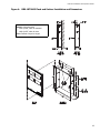
Install the enclosure as shown for the BBX-1024 in Figure 1 below. The BBX-1024DS install information is in Figure
2. For the BBX-1072A and BBX-1072ADS see Figure 3 and 4, on the following pages. Figure 5 demonstrate the
BB-5508 backbox installaltion.
Figure 1: BBX-1024 Flush or Surface Enclosure Installation and Dimensions
14.55"
1.2"
1.2"
0.2"
3.7"
28.5"
1.55"
18"
Adhere trim ring to
wall surface around
backbox.
0.2"
17.0"
1.55"
FA-UNIV-TRB
FA-UNIV-TRB
Material: 18GA (0.048”) thick cold rolled steel
Finish: Painted except for hinges
Note: Leave bottom of box conduit free for batteries.
14
FleX-NetTM Installation and Operation Manual
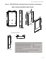
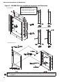
Figure 2: BBX-1024DS Flush and Surface Enclosure Installation and Dimensions
BBX-1024DS BACKBOX AND DOOR
5 3/4”
12”
14 1/2”
23 1/2”
17”
26 ”
28 ”
BACKBOX
4 1/4”
BACKBOX FRONT VIEW
1 1/2”
LEFT SIDE VIEW
DOOR
KNOCKOUT LOCATIONS
1 3/4”
2” 1 3/4”
1 3/4” 2”
2”
6”
1 3/4”
TOP VIEW
9 1/2”
Dimensions of backbox (minus built-in trim ring) 26”H x 14 1/2”W x 4 1/4” D
Horizontal distance between mounting screws
12”
Vertical distance between mounting screws
23 1/2”
Complete dimensions of enclosure with door
28”H x 17”W x 5 3/4”D
Size of Knockouts: 1”
RIGHT SIDE VIEW
Material of backbox and door: 16 GA (0.059”) thick cold rolled steel
Finish of backbox and door: Painted
15
Mechanical Installation and Dimensions
Figure 3: BBX-1072A Flush or Surface Enclosure Installation and Dimensions
Material: Cold rolled steel
16GA (0.059”) thick for backbox
14GA (0.075”) thick for door
Finish: Painted except for hinges
Note: Leave bottom of box conduit free for batteries.
16
FleX-NetTM Installation and Operation Manual
Figure 4: BBX-1072ADS Flush and Surface Installation and Dimensions
Material: Cold rolled steel
16GA (0.059”) thick for backbox
14GA (0.075”) thick for door
Finish: Painted except for hinges
17
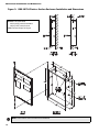
Mechanical Installation and Dimensions
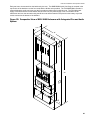
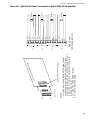
Figure 5: BB-5008 Enclosure Installation Instructions and Dimensions
BB-5008 Backbox
Material: Cold rolled steel
16GA (0.059”) thick for backbox
Backbox
14GA (0.075”) thick for door
Finish: Painted except for hinges
Backbox with DOX-5008M Door
DOX-5008M Metal Door
Note: Leave bottom of box conduit free for batteries. Mount the power supply in the same manner as shown
in Figure 4.
18
FleX-NetTM Installation and Operation Manual
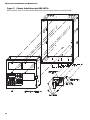
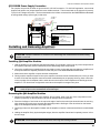
Chassis Installation
1. Group the incoming wires through the top of the enclosure to prepare it for wiring the modules. Do not run the
wires in-between the modules since it could cause a short circuit.
2. Use a wire tie to group wires for easy identification and neatness.
3. Be sure to connect a solid earth ground (from building system ground / to a cold water pipe) to the chassis
earth ground mounting lug, and to connect the earth ground wire lugs from the main chassis to the ground
screw on the backbox.
4. Mount chassis FX-2003-12N into backbox BBX-1024 using the supplied hexnuts as shown in Figure 6 below.
Figure 6: Chassis Installation into BBX-1024
14 1/2”
BACKBOX
26”
CHASSIS
GROUND
4 1/2”
Mircom FX-2000N
Fire Alarm Control Panel
Normal Condition
December 31, 2009
MENU
ENTER
CANCEL
INFO
ALARM
QUEUE
A.C. ON
SUPV.
QUEUE
PRE-ALARM
TROUBLE
QUEUE
MONITOR
QUEUE
SIGNAL
SILENCE
FIRE
DRILL
GENERAL
ALARM
SYSTEM
RESET
GND FAULT
ACKNOWLEDGE
LAMP
TEST
MAIN CHASSIS
FX-2003-12N
#8-32 HEXNUTS (4)
EARTH GROUND LUG
#8 X 1/4” TYPE ‘B’ SCREW
Note: Leave bottom of box conduit free for batteries.
19
Mechanical Installation and Dimensions
Figure 7: Chassis Installation into BBX-1072A
Mount chassis FX-2017-12N into backbox BBX-1072A using the supplied hexnuts as shown below.
2012
6
20
FleX-NetTM Installation and Operation Manual
Figure 8: Installation Instructions and Dimensions for BB-5014
BB-5014 Backbox
Backbox
Material:
Cold rolled steel
16GA (0.059”) thick
for backbox
14GA (0.075”) thick
for door
Finish: Painted except for
hinges
Backbox with DOX-5014M Door
DOX-5014M Metal Door
Note: Mount the power supply in the same manner as shown in Figure 5.
21
Mircom
Module Mounting Locations
The FX-2003-12N or FX-2017-12N Main Chassis come pre-assembled with a main panel, display components and
boards. Install the adder modules of different types as shown in the diagrams on the following pages.
Notes: For many adder modules to enable communication from the main module to all of the adder modules, it is
necessary to add a continuity jumper on the last adder module in a chain (see the appropriate module settings
section to verify the location of the continuity jumper on a particular circuit adder module). Only the last circuit
adder module should have a jumper plug on its continuity jumper; all others must be left without a jumper plug.
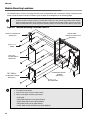
Figure 9: Module Mounting Locations View #1
PR-300 CITY TIE MODULE
(SEE NOTE 2)
MAIN CHASSIS
MODEL: FX-20XX-12N/DS
(SEE NOTE 1)
#6-32 x 1 1/4"
SCREW
UDACT-300A
DIALERMODULE
(SEE NOTE 2)
OTHERCIRCUIT ADDER
MODULE
(SEE NOTE 3)
FNC-2000 or
OTHERCIRCUIT ADDER
(SEE NOTE 3)
#6-32 x 1 1/2"
M/F HEX SPACER
Notes:
1. Front plate is not shown.
2. Position reserved for PR-300 or UDACT-300A.
3. Other circuit adder modules may include:
•
•
•
•
•
22
FNC-2000
DM-1008A Detection Circuit Adder Module
SGM-1004A Signal Circuit Adder Module
RM-1008A Relay Circuit Adder Module
ALCN-792M and ALCN-792D Loop Adder Modules
FleX-NetTM Installation and Operation Manual
Figure 10: Module Mounting Locations View #2
Main Chassis
FX-20XX-12N/DS
Provision for PR-300 or
UDACT-300A
FNC-2000 in position 2
and other Adder Module
in position 1
2
1
MD-575 Long Ribbon Cable
MD-579 Short Power Cable
MD-580 Long Power Cable
MD-579
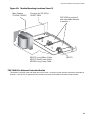
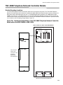
FNC-2000 Fire Network Controller Module
This module is required in the main lobby and one per node. It mounts over the main fire alarm board, preferably in
position 2. Use the four 2” spacers and four screws to secure the FNC-2000 to the main fire alarm board.
23
Mircom
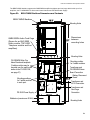
Display and Adder Modules Mounting Locations
FX-2003-12N Compact Main Chassis
Mounts in the BBX-1024 Enclosure and supports three adder modules.
Exterior View
Mircom FX-2000N
Fire Alarm Control Panel
Normal Condition
December 31, 2009
Interior View
MENU
ENTER
CANCEL
INFO
ALARM
QUEUE
SUPV.
QUEUE
A.C. ON
MONITOR
QUEUE
TROUBLE
QUEUE
CPU FAULT
SIGNAL
SILENCE
FIRE
DRILL
GENERAL
ALARM
SYSTEM
RESET
GND FAULT
LED 0
LED 4
LED 8
LED 12
LED 1
LED 5
LED 9
LED 13
LED 2
LED 6
LED 10
LED 14
LED 3
LED 7
LED 11
LED 15
ACKNOWLEDGE
CONFIGURABLE
SWITCH/LED 3
LAMP
TEST
CONFIGURABLE
SWITCH/LED 7
Slot 3 is reserved
for PR-300 or
UDACT-300A. If
not required, this
slot can be used to
mount any of the
adder modules.
3
2
1
FX-2000N
MainBoard
Board
FX-2000 Main
The recommended
mounting position is 2
for the FNC-2000. The
FOM-2000-SP board, if
used, is mounted over
the FNC-2000 board.
AC LINE
CIRCUIT
BREAKER
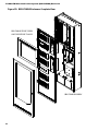
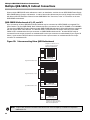
FX-2017-12N Mid-size Main Chassis
Mounts in the BBX-1072A Enclosure, and supports three display modules and 17 adder modules.
Exterior View
Cutout to mount
display module
Mircom
FX-2000N
Interior View
12
11
10
9
8
Cutout to mount
display module
17
16
15
14
13
5
4
Cutout to mount
display module
3
7
6
MENU
Fire Alarm Control Panel
Normal Condition
ENTER
CANCEL
December 31, 2009
INFO
ALARM
QUEUE
SUPV.
QUEUE
A.C. ON
1
MONITOR
QUEUE
TROUBLE
QUEUE
CPU FAULT
2
SIGNAL
SILENCE
FIRE
DRILL
GENERAL
ALARM
SYSTEM
RESET
GND FAULT
LED 0
LED 4
LED 8
LED 12
LED 1
LED 5
LED 9
LED 13
LED 2
LED 6
LED 10
LED 14
LED 3
LED 7
LED 11
LED 15
ACKNOWLEDGE
CONFIGURABLE
SWITCH/LED 3
AC LINE
CIRCUIT
BREAKER
LAMP
TEST
FX-2000N
Main
Board
FX-2000 Main
Board
CONFIGURABLE
SWITCH/LED 7
Slot 3 is reserved for PR-300 or UDACT300A. If not required, this slot can be used
to mount any of the adder modules.
The recommended mounting position is 2 for
the FNC-2000. The FOM-2000-SP board, if
used, is mounted over the FNC-2000 board.
24
FleX-NetTM Installation and Operation Manual
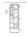
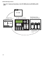
FX-2009-12N Large Main Chassis
Mounts and occupies four display positions in BB-5008 or BB-5014 Enclosures, and supports two display modules and
nine adder modules. This large chassis size can hold the integrated audio and/or telephone modules.
Exterior View
Mircom
FX-2000N
Interior View
3
MENU
2
Normal Condition
ENTER
CANCEL
INFO
SUPV.
QUEUE
A.C. ON
MONITOR
QUEUE
TROUBLE
QUEUE
CPU FAULT
SIGNAL
SILENCE
FIRE
DRILL
GENERAL
ALARM
SYSTEM
RESET
5
4
9
8
7
Cutout to mount
display module
December 31, 2009
ALARM
QUEUE
6
1
Fire Alarm Control Panel
GND FAULT
LED 0
LED 4
LED 8
LED 12
LED 1
LED 5
LED 9
LED 13
LED 2
LED 6
LED 10
LED 14
LED 3
LED 7
LED 11
LED 15
ACKNOWLEDGE
CONFIGURABLE
SWITCH/LED 3
FX-2000 MainMain
BoardBoard
FX-2000N
LAMP
TEST
CONFIGURABLE
SWITCH/LED 7
Slot 3 is reserved for PR-300 or UDACT-300A. If
not required, this slot can be used to mount any of
the adder modules.
Cutout to mount
display module
The recommended mounting position is 2 for the
FNC-2000. The FOM-2000-SP board, if used, is
mounted over the FNC-2000 board. Positions 4 to
9 are replaced with the audio and telephone
boards if used.
ECX-0012 Expander Chassis for FX-2009-12N
Mounts and occupies two display positions in BB-5008 or BB-5014 Enclosures, and supports two display and 12 adder
modules.
Exterior View
Interior View
Cutout to mount
display module
Cutout to mount
display module
6
5
4
3
2
1
12
11
10
9
8
7
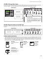
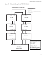
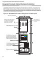
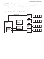
NETWORK CONTROLLER MODULES
The FNC-2000 Fire Network Controller module is mounted in position 2 over the FX-2000N main board. The TNC5000 Telephone Network Controller module is mounted over the ANC-5000 Audio Network Controller module and
both are mounted on a metal plate and that plate is mounted in a BB-5008 or BB-5014 backbox in positions marked
4 to 9 inclusive, refer to previous drawing of large chassis.
FNC-2000
0
*0
Fire Network Controller
Module
ANC-5000
TNC-5000
Audio Network
Controller
Module
Telephone
Network
Controller
Module
0!-03)NTERFACE
*0
*7
*0
*7
0
*7
*7
0.ETWORK23
023$EBUG
0(?3PEED!UDIO
023
0
*7
*7
*7
*7 *7
FOM-2000-SP
Fiber Optics Module
RX2
P1
RX1
TX2
TX1
Mounts over the
FNC-2000 Fire Network
Controller Module
25
Display and Adder Modules Mounting Locations
Adder Modules
Each adder module occupies one module slot and mounts inside the following chassis:
-
B
+
S S
-
+
-
B
COM (-)
A
P4
+
-
ALCN-792M
Quad Intelligent
Analog Loop
Adder Module.
ALARM OUT
A
Loop 1
Active LED
Loop 2
Active LED
P3
P5
P6
Daughter Board
Connector
1
8
SW1
P1
P2
+
-
B
+
A
LOOP (3)
P1
-
S S
COM (-)
To Main Board
Connector P6
+
-
B
+
-
A
LOOP (4)
ALCN-792D
Daughter Board
Analog 2 Loop
Adder Module.
Mounts over
ALCN-792M
UDACT-300A
DIgital Alarm
Communicator
Module
RM-1008A
Eight Relay
Circuit Module
SGM-1004A
Four NAC circuit
Module
DM-1008A
Eight Initiating
Circuit Module
CITY
TIE
+ | -
PR-300
Polarity Reversal/
City Tie Module
POLARITY POLARITY
REVERSAL REVERSAL
SUPV
ALARM
+ | -
+ | -
P2
+
FX-2003-12N Compact Main Chassis
FX-2017-12N Mid-size Main Chassis
FX-2009-12N Large Main Chassis
ECX-0012 Expander Chassis for FX-2009-12N
JW4
P1
•
•
•
•
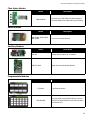
Display Modules
Each display module occupies one display position and mounts to the display cutouts on the following chassis:
•
•
•
•
FX-2003-12N Compact Main Chassis
FX-2017-12N Mid-size Main Chassis
FX-2009-12N Large Main Chassis
ECX-0012 Expander Chassis for FX-2009-12N
These modules can also be mounted in the standard BB-5000 Series enclosures which have cutouts (with brackets),
and the BBX-1000 Series enclosures (requires RAXN-LCD as a driver). “Frame” is a measure of display capacity, used
in the programming of the system.
DSPL-420
Narrow Display Control(3 Frames)
RAM-1032/TZ/TZDS
Programmable Zone LED
Annunciator Module (3 Frames)
IPS-2424/DS
Programmable Input
Switches Module (2 Frames)
DSPL-2440
Graphic Display Control(3 Frames)
RAX-1048TZ/DS
Programmable Zone/Trouble LED
Annunciator Module (3 Frames)
FDX-008/KI
Fan Damper Module (1 Frame)
Flexnet
System Normal
26
OFF
AUTO
ON
TROUBLE
OFF
AUTO
ON
TROUBLE
OFF
AUTO
ON
TROUBLE
OFF
AUTO
ON
TROUBLE
OFF
AUTO
ON
TROUBLE
OFF
AUTO
ON
TROUBLE
OFF
AUTO
ON
TROUBLE
OFF
AUTO
ON
TROUBLE
FleX-NetTM Installation and Operation Manual
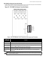
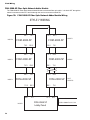
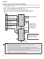
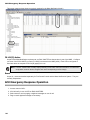
Module Settings
Main Fire Alarm Module (MD-871A “N” Version Main Chassis)
This main board has one addressable loop and network capability.
JW1
Jumper is removed if a PR-300 or UDACT-300A is installed.
JW2,JW4
Jumpers are Factory Set and should not be changed.
JW5
Normally un-installed, add jumper to silence on-board buzzer.
JW6
Normally installed, remove jumper to enable external power supply supervision.
P1,2
Factory connection to Bridge Rectifier.
P3
Black RS-485 Connector connects to the Adder Loop ALCN-792M if used (Address Loops 3 and 4)
P4
Connector for PR-300 Module or UDACT-300A.
P5
Connector for next 8 Conventional Hardwire Circuit Adder Modules (Loop 1).
P6
Connector for first 8 Conventional Hardwire Circuit Adder Modules (Loop 0).
P7
Ethernet jack.
P8
Power Connector for Adder Modules.
P9
RS-232C for Printer or “CRT” Monitor.
P10,11
Connection to 24 VDC Battery. Observe Polarity.
P14
Connector for Display Module.
P15, P18, J1 Connectors for Factory Use.
P16
High speed RS-485 audio link to ANC-5000 Audio Network Controller Module.
When connected provides ARCnet or Fibre Optic audio and telephone communication
P19
SW2
NAC PWR
Connector for FNC-2000 Fire Network Controller Module.
DIP Switch for node address.
24V FWR input terminals for additional power for signal adder modules.
F1
20 Amp slow blow non-replaceable fuse.
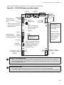
Note: To enable communication from the Main Module to all of the Adder Modules, it is necessary to add a Continuity
Jumper on the last Adder Module in a chain (see the appropriate Module Settings section to verify the location of
the Continuity Jumper on a particular Circuit Adder Module). Only the last circuit adder module should have a
jumper plug on its continuity jumper; all others must be left without a jumper plug.
TO CONFIGURE THE FIRE ALARM PANEL USE THE RS-485 CONNECTOR P4 OF THE LAST ADDER LOOP
CONTROLLER MODULE INSTALLED OR IF NOT PRESENT, P3 ON THE FleX-NetTM MAIN FIRE ALARM MODULE.
Figure 11:
Main Fire Alarm Module (MD-871A “N” Version Main Chassis)
P4
P3
FIELD WIRING TERMINALS
JW1
JW5
P16
P5
JW6
MAIN FIRE ALARM BOARD
JW4
P9
P6
P19
P14
P8
SW2
P18
P2 P1 P10 P11
+ BR - +BAT -
8
1
P7
ON
JW2
J1
P15
NAC PWR
F1
27
Module Settings
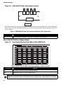
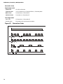
SW2 DIP Switch Node Address Setting on Main Fire Alarm Module
Refer to table in Appendix for Node Address Setting. Available addresses are 1 to 63. DIP Switch SW2-1 is the
least significant digit.
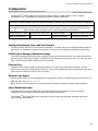
DSPL-420 Main Display Module
The DSPL-420 mounts into backboxes BB-5008(R), BB-5014(R) and BBX-FXMNS. This display is part of the
following main fire alarm chassis: FX-2003-12NDS, FX-2003-12XTDS, FX-2009-12NDS, FX-2017-NDS, and FX2000NDS.
Figure 12: DSPL-420 Main Display Module (Part of Main Chassis c/w Main Fire
Alarm Module)
P1: Cable connects to P14 of the FX-2000N main fire alarm board (Figure 11).
P2: Connection to P1 of any adder display module if used.
Note: The main display module comes with slide-in paper labels including both English and French slideins, and laser printer-compatible blanks for zone labelling.
28
FleX-NetTM Installation and Operation Manual
DSPL-2440 Graphical Main Display Module
The DSPL-2440 is a separate item. It can be mounted into backboxes BB-5008(R), BB-5014(R) and BBX-FXMNS.
It can replace the DSPL-420 found with the following models: FX-2003-12NDS, FX-2003-12XTDS, FX-200912NDS, FX-2017-NDS, and FX-2000NDS.
Figure 13: DSPL-2440 Graphical Main Display Module
MGC Network
Fire Control System
System Normal
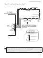
P1: Cable connects to P14 of the FX-2000N main fire alarm board (Figure 11).
P2: Connection to P1 of any adder display module if used.
Note: The main display module comes with slide-in paper labels including both English and French slideins, and laser printer-compatible blanks for zone labelling.
29
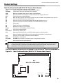
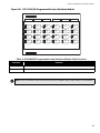
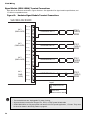
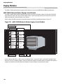
Module Settings
Main Display Module
The display module shown in Figure 14 is part of the following chassis: FX-2003-12N, FX-2009-12N, FX-2017-12N
and FX-2000ND.
Figure 14: Main Display Module (Part of Main Chassis)
P2
MGC Network
MENU
Fire Control System
System Normal
ENTER
CANCEL
March 7, 2013
INFO
ALARM
QUEUE
SUPV.
QUEUE
A.C. ON
P1
TROUBLE
QUEUE
CPU FAULT
MONITOR
QUEUE
SIGNAL
SILENCE
SWITCH/LED 0
FIRE
DRILL
SWITCH/LED 4
GENERAL
ALARM
SWITCH/LED 1
SYSTEM
RESET
SWITCH/LED 5
ACKNOWLEDGE
SWITCH/LED 2
LAMP
TEST
SWITCH/LED 6
GND FAULT
LED 8
LED 12
LED 16
LED 20
LED 9
LED 13
LED 17
LED 21
LED 10
LED 14
LED 18
LED 22
LED 11
LED 15
LED 19
LED 23
CONFIGURABLE
SWITCH/LED 3
CONFIGURABLE
SWITCH/LED 7
P1: Cable connects to P14 of the FX-2000N main fire alarm board (Figure 11).
P2: Connection to P1 of any adder display module if used.
Note: The main display module comes with slide-in paper labels including both English and French slideins, and laser printer-compatible blanks for zone labelling.
30
FleX-NetTM Installation and Operation Manual
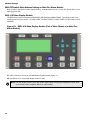
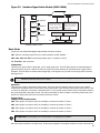
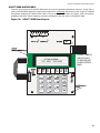
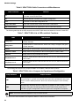
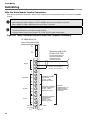
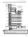
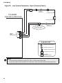
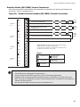
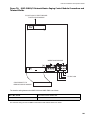
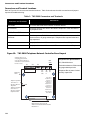
FNC-2000 Fire Network Controller Module
An FNC-2000 Fire Network Controller module is required in each fire alarm node in the system. The FNC-2000 also
provides a connection for an optional FOM-2000-SP Fiber Optics Module.
Figure 15: FNC-2000 Fire Network Controller Module
This cable
connects to
P19 on the
FX-200X-XN
Main Fire
Alarm Board
Table 1: FNC-2000 Module List of Connectors and Jumpers and Functions
CONNECTOR
OR JUMPERS
Function
P6
P6 is for Factory Use Only.
P10
P10 connects to P1 of the FOM-2000-SP Fiber Optic Network Adder Module if used.
JW1, JW2, JW4,
JW7, JW8, JW11
Jumpers for JW1, JW4, JW7, and JW10 equal Line Termination (always short).
JW5 and JW11
Leave both un-installed. Do not connect JW5 or JW11 (open)
JW3, JW6, JW9,
JW12
Jumpers for JW3, JW6, JW9, JW12 shall be present between pins 1 and 2 (far right) and
remain as is.
Jumpers for JW2 and JW8 equal Ground Fault (always short).
Note: Network connection is through twisted cable from Line A, B, C and D. Refer to Figure 35 for specific
wiring and cable information.
31
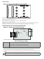
Module Settings
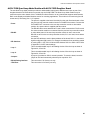
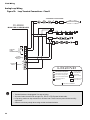
Figure 16: FOM-2000-SP Fiber Optic Network Module
RX2
RX1
TX2
TX1
P1
One of these modules is required at each panel where fiber optics will be used between them. The FOM-2000-SP
will be mounted over the FNC-2000 Network board (over the field wiring terminals) with two #6 Phillips screws and
two Hex spacers.
Table 2: FOM-2000-SP Fiber Optic Network Module Cable Connection
Connector
P1
Function
P1 cable attaches to P10 of the FNC-2000 Fire Network Controller Module.
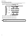
RAX-1048/TZ/TZDS Zone Display Module
Figure 17: Zone Display Module (RAX-1048 or RAX-1048TZ/DS)
P2
P1
Table 3: RAX-1048/TZ/TZDS Zone Display Module Cable Function
Connector
Function
P1
P1 Cable connects to P2 of previous display module.
P2
P2 Cable connects to P1 of next display module
Note: The zone display module comes with laser printer-compatible slide-in paper labels for zone labelling.
32
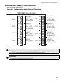
FleX-NetTM Installation and Operation Manual
Figure 18: IPS-2424/DS Programmable Input Switches Module
P2
ZONE
BYPASS
#1
ZONE
BYPASS
#5
ZONE
BYPASS
#9
ZONE
BYPASS
#13
ZONE
BYPASS
#17
ZONE
BYPASS
#21
ZONE
BYPASS
#2
ZONE
BYPASS
#6
ZONE
BYPASS
#10
ZONE
BYPASS
#14
ZONE
BYPASS
#18
ZONE
BYPASS
#22
ZONE
BYPASS
#3
ZONE
BYPASS
#7
ZONE
BYPASS
#11
ZONE
BYPASS
#15
ZONE
BYPASS
#19
ZONE
BYPASS
#23
ZONE
BYPASS
#4
ZONE
BYPASS
#8
ZONE
BYPASS
#12
ZONE
BYPASS
#16
ZONE
BYPASS
#20
ZONE
BYPASS
#24
P1
Table 4: IPS-2424/DS Programmable Input Switches Module Cable Function
Connector
Function
P1
P1 Cable connects to P2 of previous display module.
P2
P2 Cable connects to P1 of next display module
Note: The IPS-2424/DS module comes with laser printer-compatible slide-in paper labels for zone labelling.
33
Module Settings
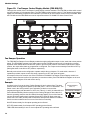
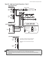
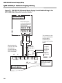
Figure 19: Fan Damper Control Display Module (FDX-008/KI)
There are two models of the Fan Damper Control Display modules available. The FDX-008 provides switch control
and LED indication of 8 fan damper zones. The FDX-008KI provides switch control of 7 fan damper zones with the
eighth zone activated by keyswitch. LED indication is provided for all 8 fan damper zones on the FDX-008KI. Both
the FDX-008 and the FDX-008KI are used in conjunction with an FX-2000N Fire Alarm Control Panel.
P2
OFF AUTO ON
TROUBLE
OFF
AUTOON ON
TROUBLE
OFF AUTO
TROUBLE
OFF AUTO ON
TROUBLE
OFF AUTO ON
TROUBLE
OFF AUTO ON
TROUBLE
OFF AUTO ON
OFF AUTO ON
TROUBLE
OFF AUTO ON
TROUBLE
TROUBLE
P1
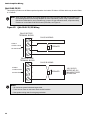
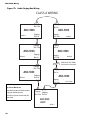
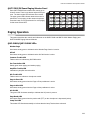
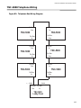
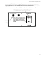
Fan Damper Operation
The FDX-008 Fan Damper Control Display module has eight configurable output circuits, each with a three position
switch. The FDX-008KI operates in the same manner as the FDX-008 except zone 8 is controlled by a remote
keyswitch. Each switch has an ON and OFF position, plus an AUTO position. If the switch is placed in the AUTO
position, the output will activate as programmed or configured. The output can be manually turned ON or OFF by
placing the switch in the ON or OFF position, respectively.
Basically each switch can be configured to operate multiple fans or dampers. For each switch, there are 3
operations provided; outputs to turn ON, same outputs to turn OFF and inputs to bypass.
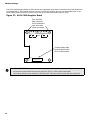
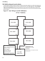
An example of the most common use of the FDX-008 or FDX-008KI Fan Damper Control Display module is to
operate exhaust fans and confirm fan operation (via monitor modules). See FDX-008 Block Diagram on the next
page for a block diagram of fan and monitor set up.
Example
As shown in the figure to the right, Parking Garage #1 has 3 exhaust fans. The three
position switch is configured to operate (to turn ON) fans 1, 2 and 3 in stairwell #1. The
switch is set in the AUTO position. Upon activation (via alarm or some other
programmed trigger) with the switch in AUTO, the 3 fans (1,2, and 3) in stairwell #1 are
turned ON automatically. Monitor modules in the Parking Garage #1 detect that all 3
fans are operating, therefore the ON LED will illuminate steadily. If one of the fans did
not turn ON (due to malfunction), both the ON and OFF LEDs will flash at the slow
trouble rate. The TRBL (trouble) LED will illuminate steady amber based on feedback
from the monitor module that one or more of the fans is not working.
ON LED shows steady for all outputs operating and confirmed.
OFF LED shows steady for all outputs NOT operating and confirmed.
TRBL LED shows steady for one or more outputs NOT operating and confirmed.
34
PARKING GARAGE #1,
FANS 1, 2 , 3
OFF AUTO ON
TROUBLE
FleX-NetTM Installation and Operation Manual
Note: A bypass function always has priority, so that if a circuit is bypassed by moving the switch
manually or by loop bypass (FX-2000N Fire Alarm Panel), no other action will operate this switch
other than again moving the switch manually or by un-bypassing the loop.
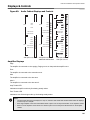
Figure 20: FDX-008 Block Diagram of Fan and Monitor Set-up
OUTPUT MODULES
FX-2000N FIRE
ALARM PANEL
FANS
OFF AUTO ON TROUBLE
MONITOR MODULES
FDX-008/KI FAN/DAMPER CONTROL MODULE
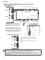
Before mounting the FDX-008KI module, if a keyswitch is to be connected, wire the keyswitch to terminals at TS1
as shown in Figure 19 below. Mount the FDX-008 and FDX-008KI Fan Damper Control Display modules in any
position on the front part of the FX-2000N chassis and backbox.
Figure 21: FDX-008KI Fan Damper Control Display Module
TS1
P2
OFF AUTO ON
TROUBLE
OFF AUTO ON
TROUBLE
OFF
ON TROUBLE
OFF AUTO ON
TROUBLE
OFF AUTO ON
TROUBLE
KEYSWITCH
CONTROLLED
OFF AUTO ON
TROUBLE
OFF AUTO ON
TROUBLE
OFF AUTO ON
TROUBLE
OFF AUTO ON
TROUBLE
P1
CONNECTS TO
PREVIOUS DISPLAY
MODULE P2
Note: There are also terminals located behind TS1 on the other side of the board for the convenience of
wiring the keyswitch. The last fan damper zone in the bottom right position of the FDX-008KI is
controlled by the keyswitch.
35
Module Settings
UUKL with FDX-008 and FDX-008KI
The models FDX-008 and FDX-00KI can be effectively use to provide an automatic and manual control system for
smoke. Refer to document number LT-966 for extensive instructions regarding UUKL applications.
Figure 22: Hardwire Detection Adder Module (DM-1008A)
FIELD WIRING TERMINALS
JW4
JW3
P4
P2
Data cable to P6 or P5 of
main fire alarm module or to
P13 or P12 of hardwire
loop controller module, or
previous adder module
JW2
JW1
Data connector for
next adder module
Power connector to P8 of
main fire alarm module,
or to P2 of hardwire loop
controller module, or to
previous adder module
Power connector for
next adder module
P1
JW5
P3
JW1: Install jumper for Class A (Style D) operation of initiating circuits 1 and 2.
JW2: Install jumper for Class A (Style D) operation of initiating circuits 3 and 4.
JW3: Install jumper for Class A (Style D) operation of initiating circuits 5 and 6.
JW4: Install jumper for Class A (Style D) operation of initiating circuits 7 and 8.
JW5: Remove continuity jumper if there are any more adder modules installed.
Note: For Class A (Style D) operation the FX-2000N must be configured as Class A via the configuration
program.
36
FleX-NetTM Installation and Operation Manual
Figure 23: Hardwire Signal Adder Module (SGM-1004A)
FIELD WIRING TERMINALS
2
P2
J11
1
P4
ZONE 4
JW5
1 2 3
ZONE 3
JW4
Data cable to P6 or P5 of
main fire alarm module
or to P13 or P12 of loop
controller module, previous adder module
Power connector to P8 of
main fire alarm module, or
to P2 of loop controller
module, or to previous
adder module
ZONE 2
JW3
Data connector for
next adder module
ZONE 1
Power connector for
next adder module
JW1
JW2
P1
P3
GREEN SIGNAL LEDs
Basic Mode
Jumpers on the SGM-1004A Signal Adder Module and their functions:
JW1: Remove continuity jumper if this is not the last adder module installed.
JW2, JW3, JW4, and JW5: Leave these jumpers open, on positions 2 and 3.
J11 Terminals: Not connected.
Components
There are four green LEDs on the board, one for each signal zone. The LED will illuminate or flash following the
signal rate sent to its zone. It will be off when the system is normal and they will illuminate when a signal zone is
activated. The LED does not reflect what is happening on the signal zone, just that it is receiving data to activate
that signal zone.
Note: Jumpers JW2, JW3, JW4 and JW5 are positioned on pins 2 and 3 (right two pins with board
orientation as shown above) from factory.
Operation
There are two modes of operation for this module. The basic mode of operation does not involve any isolators
connected to the signal zones. For this case, leave jumpers JW2, JW3, JW4 and JW5 as they come on pins 2 and
3, and do not make any connection to terminal block J11. The second mode provides mode is used when isolators
are to be connected to the signal circuits. For further information on bell cut relays or isolators, please refer to the
specific fire alarm panel manual or the isolator instruction manual.
Isolator Mode
Jumpers for the Isolator Mode
JW2: Place jumper over pins 2 and 3 for the ability to connect an isolator on Zone 1.
JW3: Place jumper over pins 2 and 3 for the ability to connect an isolator on Zone 2.
JW4: Place jumper over pins 2 and 3 for the ability to connect an isolator on Zone 3.
JW5: Place jumper over pins 2 and 3 for the ability to connect an isolator on Zone 4.
ATTENTION: Discard jumpers on zones that are not configured for isolators.
J11: Wire these terminals to an alarm relay. These may be tapped if more signal modules are used in this manner.
37
Module Settings
Figure 24: Hardwire Relay Adder Module (RM-1008A)
P4
P2
I4
I8
3 2 1
3 2 1
JP8
FIELD WIRING TERMINALS
FIELD WIRING TERMINALS
JP4
I7
I3
3 2 1
3 2 1
JP3
JP7
I6
I2
3 2 1
3 2 1
JP2
JP6
I5
I1
3 2 1
3 2 1
JP5
JP1
JW1
P3
P1
P2: Data cable to P6 or P5 of main fire alarm module, or to previous adder module.
P1: Data connector for next adder module.
P4: Power connector to P8 of main fire alarm module, or to previous adder module.
P3: Power connector for next adder module.
JW1: Remove continuity jumper if there are any more adder modules installed. If this is the last module installed, leave JW1 on.
JP1-JP8: Move jumpers from pins 1 and 2 to 2 and 3 to connect relay commons between two or more relays.
Polarity Reversal and City Tie Module (Model PR-300)
Figure 25: Polarity reversal and city tie module
POLARITY POLARITY
REVERSAL REVERSAL
SUPV
ALARM
+ | -
P2
CITY
TIE
P1
+ | -
Mounting hole for
#6-32 screws
+ | -
Mounting hole for
#6-32 screws
JW4
The following hardware configuration must be performed before installing the PR-300.
Table 5: PR-300 jumper settings
P1
Cable connects to P4 on the FX-2000N Main Fire Alarm Board
P2
Not used. If a UDACT-300A is used in conjunction with a PR-300, then the UDACT-300A
ribbon cable P1 is connected to header P2 of the PR-300.
JW4
Jumper JW4 is always left intact.
The Alarm Transmit signal to the PR-300 can be programmed to turn OFF when signal silence is active (Not allowed by UL 864
refer to Configuration section). This allows the City Tie Box to be manually reset. On subsequent alarms the silenceable signals
will resound and the City Tie Box will be retriggered. Please refer to the Configurator for more information.
The Trouble Transmit signal to the PR-300 can be programmed to delay AC power fail. Please refer to the Configurator for more
information.
Note: Jumper JW4 on the FX-2000N main fire alarm board must be removed if a city tie module is installed.
38
FleX-NetTM Installation and Operation Manual
UDACT-300A MAIN BOARD:
There are two jumpers on the UDACT-300A which are used for operation/configuration purposes. Jumper JW1 is
used to reset the default passcode. Jumper JW2 is required for configuring (which can be done using the FX-2000N
Configurator Software) the UDACT-300A. Refer to Figure 26 below for location of jumpers, cable connections,
pushbutton and LEDs. Table 6 following, provides a description of the user items on the UDACT-300A.
Figure 26: UDACT-300A Board Layout
SYSTEM NORMAL
13:21 MON 2013-02-04
CONNECT RIBBON
CABLE FROM P1
TO MIRCOM FIRE
ALARM CONTROL
PANEL
39
Module Settings
Table 6: UDACT-300A Cable Connectors and Miscellaneous
Cable Connector
Function
P1
Ribbon Cable for connecting to P4 of FX-2000N main fire alarm module or to
P2 header on the PR-300 if used.
P2
RS-232C/RS-485 Connection for computer configuration.
U18
Connector for CFG-300 Configuration Tool
Lamp Test button
Press and hold this button to test all the UDACT-300A LEDs
UR1 Potentiometer
This potentiometer is for adjustment of the CFG-300 LCD contrast.
The following table lists all the LEDs located on the UDACT-300A board and states the function of each LED.
Table 7: UDACT-300A List of LEDs and their Functions.
LEDs
LED Function
Relay Line 1
Located below Line 1 terminal block. When Line 1 relay is energized, this green
LED will illuminate
Relay Line 2
Located below Line 2 terminal block. When Line 2 relay is energized, this green
LED will illuminate.
RS-485
Status LED for communication, will flash when RS-485 communication is active.
Common Trouble
Steady amber for any troubles on the Fire Alarm panel or UDACT-300A.
CPU Fail
Steady amber for any on board CPU trouble.
Telephone Line 1
Telephone status indicator LED; Red when the line is in use, Amber when there is
a line trouble.
Telephone Line 2
Telephone status indicator LED; Red when the line is in use, Amber when there is
a line trouble.
Power ON
Green LED is ON steady when power is supplied to the board.
The following table lists the user jumpers available on the UDACT-300A and their functions.
Table 8: UDACT-300A List of Jumpers for Operation and Configuration
Jumper Number
Jumper Function
JW1
Normally open. Place jumper here and power down the UDACT-300A by
disconnecting P1 or power down the fire alarm panel (AC and Batteries), then power
back to revert to default passcode. After reset, remove the jumper. Leave normally
open.
JW2
Normally open to BLOCK remote configuration via modem, PC with a UIMA converter
module or using the LCD and keypad at the UDACT-300A. Place jumper here to
ALLOW any type of configuration. Remove jumper once configuration is complete.
Note: This module cannot be installed if a city tie module is used.
See the UDACT-300A Installation and Operation Manual LT-888 for more information.
40
FleX-NetTM Installation and Operation Manual
ALCN-792M Quad Loop Adder Module with ALCN-792D Daughter Board
The new Quad Loop Adder module provides two addressable loops plus an additional two loops as part of the
daughter board ALCN-792D which is mounted over the ALCN-792M. The Quad Loop Adder module may be
mounted over the main chassis of the FX-2000N Fire Alarm Panel or on any chassis that supports adder boards.
Refer to the Display and Adder Modules section for mounting applications. This module is mounted using four #6
screws and (if necessary) four 1 1/2" spacers.
Power
The power is supplied to the board via cable from the main fire alarm board or from
the previous loop controller module into the P1 POWER IN connector. Connect the
P2 POWER OUT connector to the next loop controller module or other adder
module. One power cable is supplied with this module.
RS-485:
The RS-485 cable comes attached at P3 and is either connected to P3 of the main
fire alarm controller module or connected from the previous loop controller module
or other adder board. If the next loop controller module is used, connect the
RS-485 out at P4 to the next loop controller module; if it is not used, leave without
connection.
DIP Switches:
Use the DIP switches to set the binary address of the board. SW1-1 is the lowest
significant digit and ON is active. For example, an address of two would be created
by turning SW1-1 OFF, SW1-2 ON and DIP switches SW1-3 to SW1-8 OFF. Refer
to Appendix C for DIP switch settings.
Loop 1:
This is the addressable loop for all initiating devices. Wire the loop as shown in
Figures 34, 35 and 36.
Loop 2:
This is the addressable loop for all initiating devices. Wire the loop as shown in
Figures 34, 35 and 36.
Jumpers:
A jumper is provided at JW2 for normal operation. To reset the board, leave the
jumper at JW2 and momentarily short the pins at position JW1.
RS-232 Debug Interface:
This connection if for factory use only.
JTAG Port:
This connection is for factory use only.
41
Module Settings
The ALCN-792D Daughter Board provides another two addressable loops when connected to the ALCN-792M Quad
Loop Adder Board. This daughter board is mounted over the ALCN-792M. Wire the two addressable loops on the
ALCN-792D Daughter Board in the same manner the ALCN-792M addressable loops are wired.
Figure 27: ALCN-792D Daughter Board
Four mounting
holes (mount to
ALCN-792M board
with screws and
spacers provided)
+
-
B
+
A
LOOP (3)
-
S S
COM (-)
+
-
+
-
B
A
LOOP (4)
Connect ribbon cable
from this board to the
ALCN-792M board P6
P1
To Main Board
Connector P6
Notes for ALCN-792D:
• All circuits are power limited and must use type FPL, FPLR, or FPLP power limited cable.
• Loop wiring: maximum loop resistance is 40 ohms total. These lines power-limited and fully supervised.
42
FleX-NetTM Installation and Operation Manual
Wire the ALCN-792M Quad Loop Adder module as shown in Figure 28 below.
Figure 28: ALCN-792M Quad Loop Adder Module
LOOP 1
+
-
B
RS-485
OUT
Green flashing
RS-485 heartbeat
LED
A
P4
+
LOOP 2
S S
-
COM (-)
+
-
B
+
Green flashing
heartbeat LED for
on board processor
RS-232
Debug
Interface
RS-485
CABLE IN
ALARM OUT
A
Loop 1
Active LED
JW2- normally shorted, a
jumper is here to enable
watchdog timer.
-
Loop 2
Active LED
P3
JW1- normally open,
pins are momentarily
shorted to reset
hardware.
P5
Four shaded
mounting holes are
for Daughter board
ALCN-792D
Top 2 holes and
bottom 2 holes are
used for the ALCN792 Quad Loop
Adder module
mounting
P6
Daughter Board
Connector
JTAG PORT
DIP SWITCHES ARE FOR THIS
BOARD’S ADDRESS. SW1-1
1
ADDRESS
IS THE LEAST SIGNIFICANT
DIP SWITCH 8
DIGIT (BINARY). ACTIVE
SW1 POSITION IS ON.
POWER CABLE
(OUT)
P2
P1
POWER CABLE
(IN)
Wiring The Addressable Loops
There are two addressable loops present on this board that are wired in the same manner as shown in
the wiring diagrams beginning with Figure 34. Although these drawings show only Loop 1;Loop 2 is wired
in the same way as Loop 1 is.
Notes for ALCN-792M:
• All circuits are power limited and must use type FPL, FPLR, or FPLP power limited cable.
• Loop wiring: maximum loop resistance is 40 ohms total. These lines power-limited and fully supervised.
43
Field Wiring
Field Wiring
Main Fire Alarm Module Terminal Connections
Wire devices to terminals as shown in below. Refer to Appendix A for specifications and to LT-1023 for compatible
devices.
ATTENTION: Do not exceed power supply ratings:
Main Chassis FX-2003-12N/DS or FX-2017-12N/DS: total current for NACs is 10A max.
Main Chassis FX-2009-12N/DS total current for NACs is 10A max.
Notes:
The terminal blocks are removable for ease of wiring.
All power limited circuits must use type FPL, FPLR, or FPLP power limited cable.
Figure 29: Main Fire Alarm Controller Board Field Terminal Connections
FX-2000N Main Fire
Alarm Controller board
P3
Shield one end of the
RS-485 LOOP ONLY
P4
RS-485 INTERFACE TO
ANNUNCIATORS AND
OTHER DEVICES
(POWER LIMITED)
+
RS485
USE TWISTED SHIELDED PAIR
22 AWG UP TO 2000 FT.
20 AWG UP TO 4000 FT.
S
S
COM
TROUBLE
NO
NC
COMMON TROUBLE
CONTACTS
24 VDC, 1 AMP
RESISTIVE LOAD
COM
ALARM
NO
AUXILIARY COMMON
ALARM CONTACTS
24 VDC, 1 AMP
RESISTIVE LOAD
NC
COM
SUPV.
NO
NC
SIG GND
or COM(-)
44
AUXILIARY COMMON
SUPERVISORY
CONTACTS
24 VDC, 1 AMP
RESISTIVE LOAD
NOT USED
MUST BE
CONNECTED TO A
LISTED POWER
LIMITED SOURCE
OF SUPPLY
FleX-NetTM Installation and Operation Manual
Figure 30: Main Fire Alarm Control board Field Terminal Connections (continued)
ANALOG
LOOP 2
CONNECTIONS
(LOOP 0 AND
LOOP1 ARE
B
INTERNAL
ADDRESSES
FOR FIRST 8
A
CARDS AND
SECOND 8
CARDS
RESPECTIVELY
LOOP 2
+
+
-
ANALOG LOOP FIELD WIRING
(CLASS A OR B)
SEE ANALOG LOOP WIRING SECTION
POWER-LIMITED, 22V DC, 400 mA MAX
Maximum Loop Resistance 40 ohms
POWER-LIMITED, REGULATED
22V DC, 400 mA MAX
5 mV Ripple
+
4-WIRE
POWER
SUPPLY
-
RTI
INTERFACE
AUXILIARY POWER
FOR REMOTE ANNUNCIATORS
24 VDC SPECIAL APPLICATION
1.7 AMPS MAXIMUM
-
4-WIRE
DETECTION
DEVICE
BLK
TRB
POWER-LIMITED
+
RTI
TRL
BLU
TO
INITIATING CIRCUIT
+
-
+
DETECTION
+
NAC 0
INDICATION
CIRCUIT 1
(POWER-LIMITED)
END OF LINE RELAY
LISTED S3403
MODEL A77-716B
MANUFACTURED BY
SYSTEM SENSOR
RED & WHT
+
AUX. POWER
(POWER-LIMITED)
CONNECTION TO MIRCOM RTI
REMOTE TROUBLE INDICATOR
(SEE RTI INSTALLATION
INSTRUCTION) BLK TO TRB+ BLU
TO TRL-RED & WHT TO AUX.
POWER COM+
-
+
+
-
3
-
2
4
1
6
5
+
POWER
-
SUPERVISED NAC # 0
STYLE Y
(CLASS B)
WIRING
SUPERVISED NAC # 1
STYLE Z
(CLASS A)
WIRING
NAC 1
INDICATION
CIRCUIT 2
(POWER-LIMITED)
+
+
+
NAC 2
INDICATION
CIRCUIT 1
(POWER-LIMITED)
+
-
SUPERVISED NAC # 2
STYLE Y
(CLASS B)
WIRING
SUPERVISED NAC # 3
STYLE Z
(CLASS A)
WIRING
NAC 3
INDICATION
CIRCUIT 2
(POWER-LIMITED)
+
+
TS2
E+
NAC External Power I+
Connection
_
TS2 Terminal Block is
located on the bottom
right corner of the main
fire alarm board
+ NOT
Legend:
BELL, HORN, OR
STROBE
3.9K 1/2W ELR LISTED S5434
MODEL MP-300 MANUFACTURED
BY MIRCOM
_ USED
Notes:
• All circuits are power limited (unless marked otherwise) and must use type FPL, FPLR, or FPLP power
limited cable.
• NACs are fully supervised and rated for 24 VDC special application, 1.7A max. They must be wired as
shown in the Wiring Tables and Information section.
45
Field Wiring
Analog Loop Wiring
Figure 31: Loop Terminal Connections - Class B
TWISTED PAIRWIRE
S
S
S
F
Conventional Heat Sensors
and Manual Pull Stations
M
FX-2000N
MAIN FIRE ALARM BOARD
SO
2 Pair
Cs
M
Cs
Cs
Cs
TWO WIRES
F
LOOP 2
ANALOG
LOOP
CONNECTIONS
H
H
H
S
F
+
B
A
+
-
+
-
4-WIRE
RESETTABLE
SUPPLY
INDICATING
CIRCUIT
NAC 0
+
+
-
LEGEND
S
Addressable Smoke Detector
with Standard Analog Base
H
Addressable Thermal Sensor
with Standard Analog Base
Cs
Conventional Smoke Sensor
M
Addressable
Monitor Module
F
Addressable Manual
Pull Station
SO
Addressable Supvr.
Output Module
Combination
Horn/Strobe
End-Of-Line-Resistor
Notes:
• Terminal blocks are “depluggable” for ease of wiring.
• All power limited circuits must use type FPL, FPLR, or FPLP power limited cable.
• Loop wiring: maximum loop resistance is 40 ohms total. These lines are power limited and fully
supervised.
• Observe in and out polarity when using module and base isolators.
46
FleX-NetTM Installation and Operation Manual
Figure 32: Loop Terminal Connections - Style 7
TWISTED PAIRWIRE
I
F
I
S
I
I
F
ADDRESSABLE
SMOKE DETECTOR
WITH ISOLATOR BASE
FX-2000N
I
MAIN FIRE ALARM BOARD
TWISTED PAIRWIRE
TWISTED PAIRWIRE
I
M
I
I
Conventional Heat Sensors
and Manual Pull Stations
H
ADDRESSABLE
THERMAL
SENSOR
WITH
ISOLATOR
BASE
Cs
LOOP 2
ANALOG
LOOP
CONNECTIONS
+
B
A
+
-
+
-
4-WIRE
RESETTABLE
SUPPLY
STYLE 7: For Style 7 operation use isolator
bases for the detectors and use isolator modules
(front and back as shown in this diagram) for the
addressable pull stations, monitor modules, and
control modules
LEGEND
S
Addressable Smoke Detector
with Isolator Base
H
Addressable Thermal Sensor
with Isolator Base
Cs
Conventional Smoke Sensor
F
I
M
Addressable Manual Pull Station
Fault Isolator Module
Addressable Monitor Module
Notes:
• All power limited circuits must use type FPL, FPLR, or FPLP power limited cable.
• Isolators need to be close nipple connected to the device being protected.
• Loop wiring: maximum loop resistance is 40 ohms total. These lines are power- limited and fully supervised.
47
Field Wiring
Figure 33: Loop Terminal Connections - Style 6 (Formerly Class A)
M
F
H
F
ADDRESSABLE
THERMAL SENSOR
TWISTED PAIRWIRE
FX-2000N
MAIN FIRE ALARM BOARD
RO
TWISTED PAIRWIRE
M
S
ADDRESSABLE
SMOKE DETECTORS
Conventional 4-Wire Smoke
Detectors, Heat Sensors
and Manual Pull Stations
LOOP 2
ANALOG
LOOP
CONNECTIONS
S
+
B
A
+
-
LEGEND
S
Addressable Smoke Detector
H
Addressable Thermal Sensor
F
Addressable Manual Pull Station
M
Addressable Monitor Module
RO
Addressable
Relay Output Module
Notes:
• All power limited circuits must use type FPL, FPLR, or FPLP power limited cable.
• Loop wiring: maximum loop resistance is 40 ohms total. These lines power-limited and fully supervised.
48
FleX-NetTM Installation and Operation Manual
Figure 34: Quad Loop Terminal Connections - Class B
ALCN-792M QUAD LOOP
ADDER MODULE
TWISTED PAIRWIRE
+
ANALOG
B LOOP 1 A
S
+
-
S
F
Conventional Heat Sensors
and Manual Pull Stations
M
TWISTED PAIR WIRE
S
S
SO
2 Pair
+
B
ANALOG A
LOOP 2
+
-
Cs
M
H
FX-2000N
MAIN FIRE ALARM BOARD
INDICATING
CIRCUIT
NAC 0
Cs
TWO WIRES
F
4-WIRE
RESETTABLE
SUPPLY
Cs
Cs
H
S
H
F
LEGEND
+
+
+
-
S
Addressable Smoke Sensor
with Standard Analog Base
H
Addressable Thermal Sensor
with Standard Analog Base
Cs
Conventional Smoke
Sensor
F
Addressable Manual
Pull Station
Combination
Horn/Strobe
M
Addressable
Monitor Module
SO
Addressable Supvr.
Output Module
End-Of-Line-Resistor
ALCN-792D DAUGHTER BOARD
+
ANALOG
B LOOP 3 A
+
-
S
This board is mounted over the ALCN-792M loop
adder module to provide four adder loops total.
Wire loops 3 and 4 in the same manner as loops
1 and 2.
S
ANALOG A
LOOP 4
B
+
+
-
Notes:
• All power limited circuits must use type FPL, FPLR, or FPLP power limited cable.
• Loop wiring: maximum loop resistance is 40 ohms total. These lines are power-limited and fully
supervised.
49
Field Wiring
Figure 35: Quad Loop Adder Module Terminal Connections - Style 7
ALCN-792M QUAD LOOP
ADDER MODULE
TWISTED PAIR WIRE
TWISTED PAIR WIRE
+
ANALOG
B LOOP 1 A
I
F
S
I
+
-
I
I
F
ADDRESSABLE
SMOKE DETECTOR
WITH ISOLATOR
BASE
S
I
S
ANALOG A
LOOP 2
B
+
+
-
TWISTED PAIR WIRE
TWISTED PAIR WIRE
M
I
I
I
ADDRESSABLE
THERMAL SENSOR
WITH ISOLATOR
BASE
Conventional Heat Sensors
and Manual Pull Stations
STYLE 7: For Style 7 operation use isolator
bases for the detectors and use isolator modules
(front and back as shown in this diagram) for the
addressable pull stations, monitor modules, and
control modules
Cs
LEGEND
S
TWISTED SHIELDED PAIR WIRE IS
NOT RECOMMENDED. IF USED THE
SHIELD SHOULD BE TERMINATED AT
THE TERMINALS MARKED SHIELD
H
Cs
F
Addressable Smoke
Sensor with Isolator Base
Addressable Thermal
Sensor with Isolator Base
Conventional Smoke Sensor
Addressable Manual Pull Station
M
ALCN-792D DAUGHTER BOARD
+
ANALOG
B LOOP 3 A
+
-
S
S
ANALOG A
LOOP 4
B
H
I
Addressable Monitor Module
Fault Isolator Module
This board is mounted over the ALCN-792M to
provide and additional two loops, for a total of four
loops.
Wire loops 3 and 4 in the same manner as loops
1 and 2.
+
+
-
Notes:
• All power limited circuits must use type FPL, FPLR, or FPLP power limited cable.
• Isolators need to be close nipple connected to the device being protected.
• Loop wiring: maximum loop resistance is 40 ohms total. These lines are power-limited and fully
supervised.
50
FleX-NetTM Installation and Operation Manual
Figure 36: Quad Loop Adder Module Terminal Connections - Style 6
TWISTED PAIR WIRE
M
F
F
H
ADDRESSABLE
THERMAL SENSOR
ALCN-792M QUAD LOOP
ADDER MODULE
RO
+
ANALOG
B LOOP 1 A
+
-
M
S
S
S
ANALOG A
LOOP 2
B
Conventional 4-Wire Smoke
Detectors, Heat Sensors
and Manual Pull Stations
+
+
-
S
ADDRESSABLE
SMOKE DETECTORS
LEGEND
TWISTED SHIELDED PAIR WIRE IS NOT
RECOMMENDED. IF USED THE
SHIELD SHOULD BE TERMINATED AT
THE TERMINALS MARKED SHIELD
S
Addressable Smoke Sensor
H
Addressable Thermal Sensor
F
Addressable Manual Pull Station
M
Addressable Monitor Module
RO
Addressable Relay Output Module
ALCN-792D DAUGHTER BOARD
+
ANALOG
B LOOP 3 A
+
-
S
S
ANALOG A
LOOP 4
B
This board is mounted over the ALCN-792M loop
adder module to provide an addition two loops, for
a total of four loops.
Wire loops 3 and 4 in the same manner as loops
1 and 2.
+
+
-
Notes:
• All power limited circuits must use type FPL, FPLR, or FPLP power limited cable.
• Loop wiring: maximum loop resistance is 40 ohms total. These lines are power-limited and fully
supervised.
51
Field Wiring
FNC-2000 Fire Network Controller Module
The FNC-2000 Fire Network Controller modules are wired from terminals marked Line A, positive and negative (see
specific cable recommended in Figure 37) to the Line B terminals of the next FNC-2000 module. Use of shielded
cable is not recommended. Wire from Line B terminals to Line A of the next FNC-2000 module. Start from the
lobby panel and wire to all the FNC-2000, wiring the last FNC-2000 back to Line B of the first FNC-2000 at the lobby
panel for Class A.
Figure 37: Style 7 Wiring for the FNC-2000 Module
STYLE 7 WIRING
Line A
Line B
FNC-2000
FNC-2000
Line A
Line B
Line B
Line A
FNC-2000
FNC-2000
Line A
Line B
Line B
Line A
FNC-2000
FNC-2000
Line B
Line A
Network Wiring Specifications
Power-Limited and Supervised
Voltage: 9V Max
Current: 800mA
Line B
Line A
Frequency: 625K Hz
Line Loss: 25 ohms
4000 feet MAX wiring distance
with twisted pair 18 gauge wire.
52
FNC-2000
Lobby Panel
RECOMMENDED CABLE:
BELDEN 5320 UJ or 5320UM
Tyco Pyro CIC
Draka Lifeline
All above cables are 2x18AWG unshielded,
low capacitance
FleX-NetTM Installation and Operation Manual
Figure 38: Redundant Wiring for the FNC-2000 Module
REDUNDANT WIRING
Line A
Line C
RECOMMENDED CABLE:
BELDEN 5320 UJ or 5320UM
Tyco Pyro CIC
Draka Lifeline
All above cables are 2x18AWG unshielded,
low capacitance
Line D Line B
FNC-2000
FNC-2000
Line B Line D
Line C Line A
Line A Line C
Line D Line B
FNC-2000
FNC-2000
Line B Line D
Line C Line A
Line A Line C
Line D Line B
FNC-2000
FNC-2000
Line C Line A
Line B Line D
Network Wiring Specifications
Power-Limited and Supervised
Voltage: 9V Max
Current: 800mA
Line A Line C
Line D
FNC-2000
Lobby Panel
Line B
Frequency: 625K Hz
Line Loss: 25 ohms
4000 feet MAX wiring distance
with twisted pair 18 gauge wiring
53
Field Wiring
FOM-2000-SP Fiber Optic Network Adder Module
The FOM-2000-SP Fiber Optic Network Adder Module is wired with fiber optic cable. It is wired OUT through the
transmit connectors marked TX and IN through the receive connectors marked RX.
Figure 39: FOM-2000-SP Fiber Optic Network Adder Module Wiring
STYLE 7 WIRING
RX 1
NODE 4
NODE 3
NODE 2
TX 2
TX 2
RX 2
RX 1
TX1
RX 1
TX 1
TX 2
RX 2
FOM-2000-SP
FOM-2000-SP
TX 2
RX 2
RX 1
TX1
RX 1
TX 1
TX 2
RX 2
FOM-2000-SP
RX 1
NODE 1
RX 2
FOM-2000-SP
FOM-2000-SP
TX 2
54
TX 1
FOM-2000-SP
RX 1
RX 2
TX 1
TX 2
FOM-2000-SP
Lobby Panel
NODE 5
NODE 6
LAST
NODE 63
TX 1
RX 2
Maximum Attenuation:
6.5dB or 2000m for 62.5/125
FleX-NetTM Installation and Operation Manual
Detection Module (DM-1008A) Terminal Connections
Wire devices to terminals as shown below. See wiring tables, and Appendix A for electrical specifications and
document LT-1023 for compatible devices.
Figure 40: Hardwire Detection Module (DM-1008A) Terminal Connections
INI 1+
INI 1STYLE B/D
INI 1
INI 2+
INI 2-
SUPERVISED INITIATING CIRCUIT #1
(ALARM ZONE) (POWER LIMITED)
STYLE B
(CLASS B)
WIRING
SUPERVISED INITIATING CIRCUIT #2
(SUPERVISORY ORWATERFLOW ZONE)
(POWER LIMITED)
STYLE B
(CLASS B)
WIRING
INI 3+
INI 3STYLE B/D
INI 2
INI 4+
SUPERVISED INITIATING CIRCUIT #3
(ALARM ZONE) SEE STYLE D NOTE (POWER LIMITED)
STYLE D
(CLASS A)
WIRING
INI 4INI 5+
INI 5STYLE B/D
INI 3
INI 6+
Style D Note: Initiating circuits of the DM-1008A
must be either all Style B (Class B)
or all Style D (Class A). If Style D is selected, the
number of circuits is cut in half.
INI 6-
Legend:
INI 7+
SMOKE DETECTOR
STYLE B/D
INI 4
INI 7INI 8+
INI 8-
HEAT DETECTOR
SUPERVISORY OR
WATERFLOW
SWITCH (NO)
3.9K 1/2W ELR LISTED S5434
MODEL MP-300
MANUFACTURED BY MIRCOM
PULL STATION
Note:
• Terminal blocks are “depluggable” for ease of wiring.
• All power limited circuits must use type FPL, FPLR, or FPLP power limited cable.
• Initiating circuits are fully supervised and rated for 22 VDC, 3 mA standby, 5 mV ripple, 50 mA max
alarm. They may be configured as required. The alarm threshold is 21 mA. Maximum loop resistance is
100 ohms, 50 ohms per side.
• All conventional hardwire initiating circuits are Compatibility ID "A".
55
Field Wiring
Signal Module (SGM-1004A) Terminal Connections
Wire devices to terminals as shown in Figure 39 below. See Appendix A for signal module specifications, and
LT-1023 for compatible devices.
Figure 41: Hardwire Signal Module Terminal Connections
SGM-1004A NAC BOARD
IND 1+ (Y/Z)
NAC 1
(POWER LIMITED)
IND 1+ (Z)
SUPERVISED NAC #1
STYLE Y
(CLASS B)
WIRING
SUPERVISED NAC #2
STYLE Z
(CLASS A)
WIRING
SUPERVISED NAC #3
STYLE Y
(CLASS B)
WIRING
SUPERVISED NAC #4
STYLE Z
(CLASS A)
WIRING
IND 1- (Z)
IND 1- (Y/Z)
IND 2+ (Y/Z)
NAC 2
(POWER LIMITED)
IND 2+ (Z)
IND 2- (Z)
IND 2- (Y/Z)
IND 3+ (Y/Z)
NAC 3
(POWER LIMITED)
IND 3+ (Z)
IND 3- (Z)
IND 3- (Y/Z)
IND 4+ (Y/Z)
NAC 4
(POWER
LIMITED)
IND 4+ (Z)
IND 4- (Z)
IND 4- (Y/Z)
Legend:
SMOKE DETECTOR
3.9K 1/2W ELR LISTED S5434
MODEL MP-300
MANUFACTURED BY MIRCOM
Notes:
• The terminal blocks are “depluggable” for ease of wiring.
• All power limited circuits must use type FPL, FPLR, or FPLP power limited cable.
• SGM-1004A NACs are fully supervised and rated for 24 VDC special application, 1.7A max. They must
be wired as shown in the Wiring Tables on page 62.
56
FleX-NetTM Installation and Operation Manual
Relay Module (RM-1008(A)) Terminal Connections
Relays are available as shown below.
Figure 42: Hardwire Relay Module Terminal Connections
RM-1008A Relay Module
COM
RLY 5
NC
NO
COM
RLY 6
NC
NO
COM
RLY 7
NC
NO
COM
RLY 8
NC
NO
AUX RELAY 5
CONTACTS
28 VDC, 1 AMP
RESISTIVE LOAD
AUX RELAY 6
CONTACTS
28 VDC, 1 AMP
RESISTIVE LOAD
AUX RELAY 7
CONTACTS
28 VDC, 1 AMP
RESISTIVE LOAD
AUX RELAY 8
CONTACTS
28 VDC, 1 AMP
RESISTIVE LOAD
COM
RLY 1
NC
NO
COM
RLY 2
NC
NO
COM
RLY 3
NC
NO
COM
RLY 4
NC
NO
AUX RELAY 1
CONTACTS
28 VDC, 1 AMP
RESISTIVE LOAD
AUX RELAY 2
CONTACTS
28 VDC, 1 AMP
RESISTIVE LOAD
AUX RELAY 3
CONTACTS
28 VDC, 1 AMP
RESISTIVE LOAD
AUX RELAY 4
CONTACTS
28 VDC, 1 AMP
RESISTIVE LOAD
Notes:
• All relay circuits are power limited and must use type FPL, FPLR, or FPLP power limited cable.
• All relay circuits must be connected to a listed power limited source of supply.
ATTENTION:
• Do not connect 120 VAC directly to these relays.
57
Field Wiring
Polarity Reversal and City Tie Module (PR-300) Wiring
Wire PR-300 Polarity Reversal and City Tie Module (if used) as shown in Figure 43 below. Power Limited cable type
FPL, FPLR or FPLP must be used.
For USA installation, the installer must use Atlantic Scientific (Tel: 407-725-8000), Model #24544 Protective
Device, or similar UL-Listed QVRG secondary protector, as shown.
For use in Canada, the Protective Device is not required but still recommended.
Figure 43: Polarity reversal and city tie module terminal connection
PR-300
+
2
S
POLARITY REVERSAL ALARM
24VDC OPEN
12VDC AT 3.5mA
8mA MAX. SHORT
+
POWER LIMITED
1
PROTECTED
+
PROTECTOR
1
UNPROTECTED
CITY TIE LOCAL ENERGY
RATED - 24VDC FILTERED
TRIP COIL - 14 Ohms, 250mA
5mV RIPPLE
1
+
2
-
S
1
+
2
2
-
S
S
POLARITY REVERSAL SUPV.
24VDC OPEN
12VDC AT 3.5mA
8mA MAX. SHORT
-
POWER LIMITED
DIN RAIL CONNECTION
TO EARTH GROUND
PROTECTOR
PROTECTOR
1
1
2
S
PROTECTED
S
UNPROTECTED
2
USE A SHORTING WIRE WHEN
THE CITY TIE IS NOT USED
1
+
2
-
CONFORMS TO NEMA
STANDARD 2011 INTENDED
FOR CONNECTION TO
POLARITY REVERSAL CIRCUIT
OF A REMOTE STATION
RECEIVING UNIT HAVING
COMPATIBLE RATINGS
S
1
2
POWER LIMITED CABLE TYPE FPL,
FPLR or FPLP MUST BE USED
FROM PR-300 TO PROTECTORS.
S
DIN RAIL CONNECTION
TO EARTH GROUND
Notes:
• Either the PR-300's city tie or polarity reversal interface may be used, but not both.
• The city tie interface is not power limited.
• Plug PR-300 ribbon cable (P1) into connector (P4) of the FX-2000N main fire alarm module.
• Cut jumper (JW1) on the PR-300 module in order to transmit a trouble condition to the monitoring station.
• Remove jumper plug from jumper JW4 on the main fire alarm module.
• The polarity reversal interface is power limited and must use type FPL, FPLR, or FPLP power limited
cable.
• For polarity reversal operation, short the city tie connection.
58
FleX-NetTM Installation and Operation Manual
UDACT-300A Main Board Terminal Connections
Wire the two telephone lines to RJ31X Connector terminals as shown in Figure 44 below. The UDACT-300A
terminals are located on the top left hand corner of the board. If using a cellular or wireless service, use the Line 2
interface connection only.
Note: Most Authorities Having Jurisdiction (AHJ) do not allow the connection of premise
telephones, see specifications for more information.
Figure 44: Telephone Line Wiring Diagram
7,3
5,1*
5-;
3XEOLFVZLWFK
7HOHSKRQHFRPSDQ\
ZLULQJ
7,3
7
5
5(6
7
SUHPLVHWHOHSKRQH
,)SHUPLWWHG
5('
*5((1
*5(<
%52:1
5,1*
5
&2
/,1(
/LQHLV:LUHGDVVKRZQIRU/LQH
7
5
5(6
7
5
&2
/,1(
8'$&7$
59
Field Wiring
Power Supply Connections
The power supply is part of the main chassis. The ratings are outlined in the table below.
Model
Electrical Input Ratings
Power Supply
Total Current
Battery Fuse on Main
Module
FX-2003-12N/DS & FX-201712N/DS Main Chassis
120 VAC, 60 Hz, 2A /
240VAC, 50hz, 1A
12 amps maximum
20 Amp, 1-1/4" Slow Blow
Non-replaceable Fuse
FX-2009-12N/DS Main
Chassis
120 VAC, 60 Hz, 2A /
240VAC, 50hz, 1A
12 amps maximum
20 Amp, 1-1/4" Slow Blow
Non-replaceable Fuse
All Chassis’
IN-LINE 20 Amp, 1 1/4” Fast Acting Fuse, positive side of Battery Connection
See Appendix A for more power supply specifications. Wire as shown below with proper gauge wire.
Figure 45: Power Supply Connections
CONNECT GREEN
EARTH GROUND WIRE
TO MAIN MODULE PCB
MOUNTING SCREW.
P10
P11
P13
P12
20 Amp, 1 1/4” SLOW
BLOW FUSE
+
TO DEDICATED
BRANCH CIRCUIT
RED
TO 24 VDC
BATTERY
FUSE
BAT
GND
BLACK
L
L
N
G
20 Amp, 1 1/4” IN-LINE
FAST ACTING FUSE
GREEN
CAUTION:
• To prevent sparking, connect batteries after the system’s main A.C. power is turned ON.
• Do not exceed power supply ratings.
• Adhere to voltage markings as specified on labels.
60
FleX-NetTM Installation and Operation Manual
Wiring Tables and Information
Table 9: Wiring Table for Initiating Circuits.
Wire Gauge
Maximum Wiring Run to Last Device (ELR)
(AWG)
ft.
m
22
2990
910
20
4760
1450
18
7560
2300
16
12000
3600
14
19000
5800
12
30400
9200
Note: Maximum loop resistance should not exceed 100 Ohms.
Table 10: Wiring Table for NACs
Main board NACs are rated for 1.7 amps each. The SGM-1004A NACs are rated for 1.7 amps each.
Total Signal
Load
Maximum Wiring Run to Last Device (ELR)
18AWG
16AWG
14AWG
12AWG
Max Loop
Resistance
0hms
Amperes
ft.
m
ft.
m
ft.
m
ft.
m
Ohms
0.06
2350
716
3750
1143
6000
1829
8500
2591
30
0.12
1180
360
1850
567
3000
915
4250
1296
15
0.30
470
143
750
229
1200
366
1900
579
6
0.60
235
71
375
114
600
183
850
259
3
0.90
156
47
250
76
400
122
570
174
2
1.20
118
36
185
56
300
91
425
129
1.5
1.50
94
29
150
46
240
73
343
105
1.2
1.7
78
24
125
38
200
61
285
87
1.0
Note: Maximum voltage drop should not exceed 1.8 volts.
61
Field Wiring
Table 11: Analog Loop Wiring
Wire Gauge (use
twisted pair)
Loop Total (Out and In) Maximum
Twisted Pair Wire Run
(AWG)
ft.
m
12
10,000
3049
14
7971
2429
16
4980
1518
18
3132
955
Note:
• Line capacitance shall not exceed 0.5 mF.
• Inductance shall not exceed 1 mH.
• Resistance shall not exceed 40 ohms.
Power Wiring: Use Table 10: Wiring Table for NACs on the previous page to see the wiring information for the
remote annunciator being used.
RS-485 Wiring: See the wiring information for the remote annunciator being used.
4-Wire Smoke Wiring: The maximum allowable current is 0.2 amperes. The maximum allowed voltage drop is 1
volt. Refer to Table 10: WIring for NACs on the previous page.
Shield for Analog Loop Wiring: Only twisted pair is recommended, but if shielded twisted pair is used, wire shield
at the start and the end of the loop to the terminals marked Shield at the loop adder board.
62
FleX-NetTM Installation and Operation Manual
System Checkout
Before Turning the Power On
1. To prevent sparking, do not connect the batteries. Connect the batteries after powering the system from the
main AC supply.
2. Check that all modules are installed in the proper location with the proper connections.
3. Check all field (external) wiring for opens, shorts, and ground.
4. Check that all interconnection cables are secure, and that all connectors are plugged in properly.
5. Check all jumpers and switches for proper setting.
6. Check the AC power wiring for proper connection.
7. Check that the chassis is connected to EARTH GROUND (cold water pipe). Refer to NFPA 70.
8. Make sure to close the front cover plate before powering the system from main AC supply.
Note: When using Class A and isolators on an addressable loop, configure system as Class B, wire loop as
Class A, except do not connect the last device back to the panel. Do a system checkout. Then
connect the return of the Class A circuit and configure as Class A.
Power-Up Procedure
1. After completing the above procedures, power up the panel (AC only). The green AC On LED and the Common Trouble LED should illuminate, and the buzzer should sound.
2. Press the System Reset button. Since the batteries are not connected, the Battery Trouble LED should
illuminate, the trouble buzzer should sound intermittently, and the Common Trouble LED should flash.
3. Connect the batteries while observing correct polarity: the red wire is positive (+) and the black wire is negative
(-). All indicators should extinguish except for the AC On LED and the LCD should show a normal status
condition.
4. Auto-Configure or PC Configure the fire alarm control panel as described in the Configurator Guide.
Troubleshooting
Message
Description
Circuit Trouble
Normally when a circuit trouble occurs, its designated trouble indicator will be illuminated,
as well as the Common Trouble indicator and Trouble buzzer. To correct the fault, check
for open wiring on that particular circuit loop or see if the circuit disconnect switch is in the
ON or CLOSED position. Note: disconnecting a circuit will cause a system trouble (offnormal position).
Ground Fault
The FX-2000N panel has a Common Ground Fault Detector. To correct the fault, check for
any external wiring touching the chassis or other earth ground connection.
Battery Trouble
Check for the presence of batteries and their condition. Low voltage (below 20.4V) will
cause a battery trouble. If battery trouble condition persists, replace the batteries as soon
as possible.
63
Mircom
Indicators, Controls, and Operation
Refer to Figure 46 below for LED indicators, control buttons, and switches locations.
Figure 46: Indicators and Control Location
LCD Display - four lines,
20 characters per line
Cursor buttons,
ENTER, MENU, CANCEL, INFO
Mircom FX-2000N
Queue controls and
indicators for Alarm,
Supervisory, Trouble,
and Monitor
MENU
Fire Alarm Control Panel
Normal Condition
ENTER
CANCEL
January 6, 2013
INFO
Indicators for AC On,
CPU Fault, and Ground
Fault (GND FAULT)
ALARM
QUEUE
A.C. ON
16 configurable
bi-coloured zone
indicators and 16
trouble indicators
LED 8
SUPV.
QUEUE
TROUBLE MONITOR
QUEUE
QUEUE
FIRE
DRILL
SWITCH/LED 4
GND FAULT
CPU FAULT
LED 12
SIGNAL
SILENCE
SWITCH/LED 0
LED 16
LED 20
LED 9
LED 13
LED 17
LED 21
LED 10
LED 14
LED 18
LED 22
LED 11
LED 15
LED 19
LED 23
GENERAL
ALARM
SYSTEM
RESET
SWITCH/LED 1
SWITCH/LED 5
ACKNOWLEDGE
LAMP
TEST
SWITCH/LED 2
SWITCH/LED 6
CONFIGURABLE
CONFIGURABLE
SWITCH/LED 7
SWITCH/LED 3
Controls & Indicators for Signal
Silence, General, Alarm,
Acknowledge, Fire Drill, System
Reset, Lamp Test
Two configurable
switches & amber LEDs
LED indicators are amber (trouble or supervisory), red (alarm), or green (AC On), and may illuminate continuously
(steady) or at one of two flash rates:
• Fast Flash: 120 flashes per minute, 50% duty cycle
• Trouble Flash: 20 flashes per minute, 50% duty cycle
Note: The General Alarm LED and pushbutton, and the Acknowledge LED and pushbutton, are active only
on a system configured for “Two Stage.”
Paper Labels for Buttons and Indicators
Buttons and indicators are supplied with paper labels. These labels slide into the plastic label templates on the face
of the panel. Paper labels allow for easy English / French selection and custom-printed zone information.
64
FleX-NetTM Installation and Operation Manual
Common Indicators
Indicators
Description
The Buzzer is activated by any of the following
Buzzer
Fire Alarm
Supervisory Alarm
Trouble
Monitor
-
Steady
Fast Rate
Trouble Rate
Configurable to sound at Trouble Rate
If the Buzzer is turned on in response to a Non-Latching Trouble or Supervisory, it
will be turned off if the condition causing it goes away and there is no other reason
for it to be on.
AC On LED
The AC On Indicator is activated steady green while the main AC power is within
acceptable levels. It is turned off when the level falls below the power-fail threshold
and the panel is switched to standby (battery) power.
Alarm Queue LED
The Common Alarm LED flashes red whenever the Panel is in Alarm. An alarm
results from any alarm on any point or input programmed as Alarm or activation of
the manual red General Alarm Button (if the Panel is set for Two Stage Operation).
The Alarm Queue LED will go steady, once all alarms in the queue have been
reviewed using the Alarm Queue button. Since all Alarms are latched until the Panel
is reset, the Common Alarm LED will remain on until then.
Supervisory Queue LED
The Common Supv. (Supervisory) LED flashes amber at the Fast Flash Rate when
there is a Supervisory Alarm in the Panel, as the result of any Latching or NonLatching Supervisory Circuit. The LED turns off if all Non-Latching Supervisory
Circuits are restored and there are no Latching Supervisory Circuits active. The
Supv. Queue LED will go steady, once all supervisory alarms in the supervisory
queue have been reviewed using the Supv. Queue button. Latching Supervisory
Alarms remain active until the Panel is reset.
Trouble Queue LED
The Common Trouble LED flashes amber at the Trouble Flash Rate when there is
any Trouble condition being detected on the panel. It is turned off when all NonLatching Troubles are cleared. The Trouble Queue LED will go steady, once all
troubles in the trouble queue have been reviewed using the Trouble Queue button.
Monitor Queue LED
The Monitor Trouble Indicator flashes amber at the Trouble Flash Rate when there is
any Monitor condition being detected on the panel. It is turned off when all Monitors
are cleared.
CPU Fault LED
The CPU Fault Indicator is flashed yellow at the Trouble Flash Rate if the CPU is
faulty.
Fire Drill LED
The Fire Drill Indicator turns on steady amber while Fire Drill is active.
Acknowledge LED
If the Panel is configured as Two Stage, the Acknowledge Indicator flashes amber at
the Fast Flash Rate while the Auto General Alarm Timer is timing out. It turns on
steady amber when that Timer is cancelled by activating the Acknowledge or Signal
Silence buttons. If the Auto General Alarm Timer times-out and puts the Panel into
General Alarm, the Indicator is turned off.
General Alarm LED
In Two Stage Operation only, the General Alarm Indicator is activated steady red
when General Alarm is activated due to the red General Alarm button being pushed,
a General Alarm Initiating Circuit being activated, or the Auto General Alarm Timer
timing out. Once the General Alarm Indicator has been turned on it will stay active
until the Panel is reset.
Signal Silence LED
The Signal Silence indicator is flashed amber, at the trouble rate when Indication
Circuits are Silenced either by the Signal Silence button, or by the Auto Signal
Silence Timer. It is turned off when the Signals are re-sounded by a subsequent
Alarm.
Ground Fault LED
The Ground Fault Indicator flashes amber at the Trouble Rate when the Ground
Fault Detector detects a Ground Fault on any field wiring. It turns off immediately
when the Ground Fault is cleared.
65
Indicators, Controls, and Operation
Common Controls
LCD Display:
The display is a large 4 line by 20 character back-lit alphanumeric LCD. It displays information on the panel and its
devices. There are cursor buttons for menu selection and control. Information provided by the LCD display is an
alarm log, an event log, current levels, device information, verification and maintenance reports.
Queue Buttons
Use the queue buttons to select a particular queue to review.
• Use the Alarm Queue button to view all alarms. Pressing this button will show the latest alarm on the LCD
display. Use
and
to view all previous alarms.
• Use the Supervisory Queue button to view all supervisory conditions. Pressing this button will show the latest
supervisory information on the LCD display. Use
and
to view all previous supervisory conditions on
the LCD display.
• Use the Trouble Queue button to view all trouble conditions. Pressing this button will show the latest trouble
condition on the LCD display. Use
and
to view any previous troubles.
• Use the Monitor Queue Button to show all monitor conditions. Pressing this button will show the latest monitor
information on the LCD display. Use
and
to view all queued monitor conditions.
Queues are displayed on the screen according to a priority sequence. Queue priority ranking from highest to lowest
is as follows: alarm, supervisory, trouble, and monitor. If, for example, you are viewing a monitor queue and an alarm
occurs, the display will immediately display the alarm condition. Also, if there is no activity on the system for 10
seconds after you have pressed a queue button, the display will switch to the highest priority condition.
Cursor Buttons
These four buttons around the Enter Button are used for up (previous), down
(latest), left, and right selection of items on the LCD Display.
Enter Button
This button is used to select a displayed item on the LCD Display.
MENU
ENTER
CANCEL
INFO
Cancel Button
This button is used to cancel an operation.
Menu Button
This button is used to initiate the FX-2000N Menu System.
Info Button
This button is used to get more details about a displayed item.
66
SIGNAL
SILENCE
FIRE
DRILL
GENERAL
ALARM
SYSTEM
RESET
ACKNOWLEDGE
LAMP
TEST
CONFIGURABLE
CONFIGURABLE
SWITCH/LED 3
SWITCH/LED 7
FleX-NetTM Installation and Operation Manual
System Reset Button
The System Reset button causes the Fire Alarm Control Panel, and all Circuits, to be reset
• Resets all Latching, Trouble Conditions
• Resets all Initiating Circuits
• Resets 4-Wire Smoke Supply and Aux. Power Supply
• Turns off all NACs
• Turns off Signal Silence, Ack & GA Indicators
• Turns off Fire Drill
• Stops and resets all Timers
• Processes inputs as new events
• Aux Disconnect is not affected
• Reset cannot be activated until the Signal Silence Inhibit timer has expired.
Signal Silence Button
Activation of the Signal Silence button when the Panel is in Alarm, turns on the Signal Silence Indicator and
deactivates any Silenceable NACs. Non-Silenceable Circuits are unaffected. Signals will re-sound upon any
subsequent Alarm. This button does not function during any configured Signal Silence Inhibit Timer period. It also
does not function if the NACs are active as the result of a Fire Drill. In a Two Stage System, if the Auto General
Alarm Timer has timed out, this Signal Silence button also performs the same function as the Acknowledge button.
Fire Drill Button
The Fire Drill button activates all programmed and non-Disconnected NACs, but does not transmit any Alarms via
the City Tie, or Common Alarm Relay. Fire Drill may be programmed to operate specific NACs. Fire Drill is
cancelled by pressing the button again (toggle switch), or if the Panel goes into a real Alarm.
Acknowledge Button (Two Stage Only)
If the Panel is not configured for Two Stage Operation, this button does nothing. If the Panel is configured for Two
Stage Operation, activation of the Acknowledge button while the Auto General Alarm Timer is timing (there is an
Alarm in the Panel, but it is still in the First Stage), that timer is cancelled, and the Acknowledge Indicator is on
steady amber.
General Alarm Button (Two Stage Only)
If the Panel is not configured for Two Stage Operation, this button does nothing. If the Panel is configured for Two
Stage Operation, activation of the General Alarm button immediately sends the Panel into Second Stage - General
Alarm. It will also re-activate the Signals if they have been Silenced during General Alarm. The General Alarm
condition remains active until the Panel is reset.
Lamp Test Button
Activation of the Lamp Test button turns all front panel Indicators on steady in whichever colour they would normally
be activated and turns the buzzer on steady. If Lamp Test is active for more than 10 seconds, Common Trouble is
activated.
67
Indicators, Controls, and Operation
Single Stage Operation
In a single stage system, all alarm inputs are treated in a similar manner. Alarm inputs include any of the following:
non-verified alarm, verified alarm, sprinkler alarm, water-flow alarm, and general alarm circuits. Any of these alarm
inputs occurring when the panel is not already in alarm cause the following:
• The buzzer sounds steadily
• If fire drill is active, it is cancelled
• The Common Alarm LED turns on
• The Common Alarm relay activates if Aux disconnect is not active
• The Auto Signal Silence timer, if configured, starts
• The Signal Silence Inhibit timer, if configured, starts
• All non-disconnected NACs programmed to the input are activated provided that Aux disconnect is not active
• Non-disconnected strobes associated with the input are activated
• Non-disconnected signals associated with the input are activated at the evacuation rate
Subsequent alarms when the panel is already in alarm, cause the following:
• The alert buzzer sounds steadily
• If Signals have been silenced, they are resounded, the Signal Silence LED turns off, and the Auto Signal
Silence timer, if configured, is restarted
• Any additional non-disconnected strobes associated with the input are activated continuously
• Any additional non-disconnected signals associated with the new input are activated at the evacuation rate
Two Stage Operation
In a two stage system, alarm inputs are either first stage (alert) inputs or second stage (general alarm) inputs. First
stage inputs include inputs from the following types of circuits: non-verified alarm, verified alarm, sprinkler alarm,
and water-flow alarm. Second stage inputs include alarms on the general alarm circuits, activation of the General
Alarm button, or expiration of the Auto General Alarm timer. Any of these alarm inputs occurring when the panel is
not already in alarm cause the following:
•
The buzzer sounds steadily
•
If fire drill is active, it is cancelled
•
The Common Alarm LED turns on
•
The Common Alarm relay activates if Aux disconnect is not active
•
The Auto Signal Silence timer, if configured, starts
•
The Signal Silence Inhibit timer, if configured, starts
•
All Non-disconnected indicating programmed to the input are activated provided that Aux disconnect is not
active
If the alarm is a second stage alarm,
• All non-disconnected strobe circuits are activated continuously
• All non-disconnected signal circuits are activated at the evacuation rate
• The General Alarm LED turns on.
If the alarm is a First Stage alarm,
• Non-disconnected strobe circuits programmed to that circuit are activated continuously
• Non-disconnected signal circuits programmed to that circuit are activated with the alert code
• The Auto General Alarm timer, if configured, starts
• The Acknowledge LED starts flashing.
Subsequent First Stage alarms when the panel is already in alarm, cause the following:
68
FleX-NetTM Installation and Operation Manual
• The buzzer sounds steadily
• If signals have been silenced as a result of the silence button or the Auto signal silence timer, signals are
resounded as they were before signal silence, the Signal Silence LED turns off, and the Auto Signal Silence
timer, if configured, is restarted
• If the panel is not already in General Alarm, additional non-disconnected signals programmed to the new input
are activated with the Alert Code (see Indicating (Signal) Circuit Types section).
• If the panel is not already in General Alarm and if the Acknowledge LED is on steady indicating that the Auto
General Alarm timer has been Acknowledged the timer is restarted and the Acknowledge LED is extinguished.
A second stage alarm (general alarm) when the panel is already in alarm causes the following:
• The buzzer sounds steadily
• All non-disconnected signals are activated at the evacuation rate
• If the Signal Silence LED is on, it turns off and the Auto Signal Silence timer, if configured, is restarted
• The Acknowledge LED if on, turns off
Alarm inputs are latching: they remain active until system reset.
Note: If the system is configured for correlations, any second stage / general alarm condition activates all
NACs whether they are correlated or not.
Pre-Signal Operation
To configure the panel for pre-signal, all alarm inputs must be correlated to one NAC circuit that is wired to a
Notification Appliance in the Control Room that is constantly monitored by an Operator. Using the FX-2000N
Configurator, “Subsequent Alarm” in “Common System Status” must be correlated to turn on the Remaining NAC
circuits in the system. To confirm the alarm (i.e. subsequent alarm) the operator can press the “General Alarm”
button on the panel or activate a Manual Station in the Control Room.
Note: Pre-Signal is not permitted to be used in Canada, unless approved by the AHJ.
69
Indicators, Controls, and Operation
Circuit Types
The term circuits refers to an actual electrical interface, either initiating (detection) or indicating (signal). The term zone is a
logical concept for a fire alarm protected area, and will consist of at least one circuit. Often the terms zone and circuit are used
interchangeably, but in this manual the term circuit is used.
Initiating (Detection) Circuit Type
Initiating (Detection) Circuit
Type
Description
Non-Verified Alarm
This is a "normal" type of alarm which may have pull stations, smoke detectors, or heat
detectors attached. Any activation of these devices will immediately result in an alarm
condition in the fire alarm control panel. An alarm condition causes the associated
circuit Status LED and the Common Alarm LED to illuminate red.
Verified Alarm
These alarms are verified by a reset and timing procedure, and may have Manual
Stations, smoke detectors attached. Any activation of Manual Stations will result in an
alarm condition in the fire alarm control panel within four seconds. Smoke detectors will
be verified for a real alarm within 60 seconds depending upon the start-up time of the
smoke detectors being used. If four seconds is too long a response time for pull
stations, then they should be wired separately on a non-verified alarm circuit. An alarm
condition causes the associated circuit Status LED and the Common Alarm LED to
illuminate red. Verified Alarm is not permitted for heat detectors, 4-wire smoke detectors
and smoke detectors with built-in alarm verification. Refer to Appendix D Alarm
Verification for details.
Water-Flow Alarm
An alarm for water-flow sensors. These alarms are identical to normal non-verified
alarms except that any NACs programmed to these circuits (all are by default) are nonsilenceable. Also, if water-flow retard operation is enabled, then these circuits are
sampled every one second; if ten samples are active within any 15 second interval, the
water-flow alarm is confirmed and processed. An alarm condition causes the associated
circuit Status LED and the Common Alarm LED to illuminate red.
Note: Do not use the retard operation with any external retarding device;
maximum retard may not exceed 120 seconds.
Sprinkler Alarm
An alarm for sprinkler flow sensors. These alarms are identical to normal non-verified
alarms unless the water-flow retard operation is enabled. If water-flow retard operation
is enabled, then these circuits are sampled every one second; if ten samples are active
within any 15 second interval, the sprinkler alarm is confirmed and processed. An alarm
condition causes the associated circuit Status LED and the Common Alarm LED to
illuminate red.
Note: Do not use the retard operation with any external retarding device;
maximum retard may not exceed 120 seconds.
General Alarm
These alarms provide remote general alarm such as for remote key switches. In a two
stage system, these inputs perform exactly the same function as the front panel or
remote annunciator general alarm button. In a single stage system, these inputs act the
same as non-verified alarms, but if correlations are enabled, general alarm initiating
circuits are correlated to all NACs.
Non-Latching Supervisory
These alarms are for supervisory devices. An activation on these circuits will cause the
Circuit Status LED and the Common Supervisory LED to illuminate amber. The buzzer
will sound continuously. If the circuit activation is removed, the supervisory condition will
clear (so long as there are no other supervisory conditions in the system) and the circuit
Status LED will extinguish.
Latching Supervisory
These alarms are for supervisory devices. An activation on these circuits will cause the
Circuit Status LED and the Common Supervisory LED to illuminate amber. The buzzer
will sound continuously. If the circuit activation is removed, the Supervisory condition will
not clear.
70
FleX-NetTM Installation and Operation Manual
Initiating (Detection) Circuit
Type
Description
Monitor
This is a supervised general purpose non-latching input used mainly for correlating to a
relay circuit. No other system condition occurs as a result of its activation (short-circuit),
although it is supervised for trouble (open-circuit).
Trouble-Only
This circuit is used for monitoring a trouble condition from an external device such as a
Mircom Series 500 Audio System. Both open and short circuits generate a non-latching
trouble condition.
Indicating (Signal) Circuits Types
Indicating (Signal) Circuit Type
Description
Silenceable Signal
For audible devices such as bells and piezo mini-horns that may be silenced either
manually or automatically. While sounding, these follow the pattern appropriate for the
condition: the configured evacuation code (default is temporal code) during single-stage
alarm, or two stage general alarm, or the alert code during a two stage system's alert
(first) stage.
Non-Silenceable Signal
For audible devices such as bells and piezo mini-horns that may not be silenced either
manually or automatically. While sounding, these follow the pattern appropriate for the
condition: the configured evacuation code (default is temporal code) during single-stage
alarm, or two-stage general alarm, or the alert code during a two stage system's alert
(first) stage.
Coded Signal
For audible devices such as bells and piezo mini-horns that may be activated in code.
The code consists of 4 digits with each digit consisting of 1-15 pulses on the signals.
Each coded circuit can sound the complete code 1 to 15 times after which signals go
silent or revert to programmed General Alarm rate.
Note: The NFPA-72 and ULC-S527 specify temporal tone. However, for retrofits of
systems that were previously approved, coded signalling is allowed.
Strobe
For visual devices such as strobes that use no code patterns (they are continuous).
71
Indicators, Controls, and Operation
Evacuation Codes
Single stage codes
Continuous
On 100% of the time
Temporal Code
3 of 0.5 second on, 0.5 second off then, 1.5 second pause
March Code
0.5 second on, 0.5 second off
California Code
5 seconds on, 10 seconds off
Two-stage codes:
Alert Code
0.5 second on, 2.5 seconds off
General Alarm
Evacuation code as selected from above.
Figure 47:
Evacuation Codes
CONTINOUS
0.5s
1.5s
TEMPORAL CODE
0.5s
MARCH CODE
0.5s
0.5s
5s
10s
0.5s
2.5s
72
CALIFORNIA CODE
ALERT CODE
FleX-NetTM Installation and Operation Manual
Configuration
The FleX-NetTM network system which includes FX-2003-12N/DS, FX-2009-12N/DS, FX-2017-12N/DS,
FX-2000ND/S and FX-2000MNS is configured using Mircom software MSW-025.
NOTICE TO USERS, INSTALLERS, AUTHORITIES HAVING JURISDICTION, AND OTHER INVOLVED PARTIES
This product incorporates field-programmable software. In order for the product to comply with the requirements in
the Standard for Control Units and Accessories for Fire Alarm Systems, UL 864, certain programming features or
options must be limited to specific values or not used at all as indicated below.
Program feature or option
Permitted in UL 864? (Y/N)
Possible settings
Settings permitted in UL 864
Alarm Transmit Silence
No
Enabled or Disabled
Disabled or unchecked
Configuration Backup, Query and Fast-Forward
The panel supports previous, current and next configuration. The panel can be load configured without taking the
panel off-line. Configuration reverts back to previous or moves to future configuration through front-panel menu.
OPEN Graphic Navigator Software Package
This software package (OPEN GN) allows 3D graphic display of premises and devices. It provides unlimited floor
plans and events, node and job support. It supports input file formats for floors such as .svg, .dxf, .pdf, .png, .wmf,
.jpeg. Device icons and state animations can be customized.
Ethernet Port
Integrated TCP/IP Stack, Hardware based MAC address. Provides a fully configurable IP address. Use this
ethernet port to connect to OPEN graphics software. This port also provides web server for diagnostic and system
report via LAN or WAN connection on-site or remotely.
Boolean Logic Engine
Boolean logic functions are now available within the configuration software. Sophisticated logic functions such as:
AND, OR, NOT, ANY n of m, >, <, >=, <>
Built-in timers or user configurable timers and intervals and schedules available to support UUKL operations.
uBoot Based BootLoader
This program (inherent in the configuration) provides leading technology that allows a choice of multiple
configuration files or firmware revisions to support site-specific requirements.
The FleXBootTM shell offers UNIX style commands for directory listing, log download, diagnostic probing and
system tuning and optimization.
73
Typical FleX-NetTM System Layouts with Audio
Typical FleX-NetTM System Layouts with Audio
The following figures show two typical applications for the FleX-NetTM system with audio.
Figure 48 below shows a typical FleX-NetTM system layout with the main lobby control panel as Node 1 and the
combination Fire Alarm and Audio Network systems as Node 2 and 3. The diagram also shows addressable fire
alarm loops, paging and telephone connections and audio cabinets.
Figure 48: Typical FleX-NetTM System with Audio Nodes
Five Telephone Audio Channels
Audio Channels for paging,
pre-recorded messages and tones
Addressable Loop
Five Telephone Audio Channels
Audio Channels for paging,
pre-recorded messages and tones
Addressable Loop
1 twisted pair for
ARCnet Network,
Audio and Telephone
CACF
Central Alarm and Control Facility
-addressable fire alarm control
-master telephone handset
- telephone zone selector modules
-master paging microphone
-paging zone selector modules
-bypass switch modules
-fan damper control modules
-LED annunciator modules
Node 1
74
FleX-NetTM Installation and Operation Manual
Figure 49 below shows the FleX-NetTM fire alarm and audio shown within the Integrated Network Fire/Audio cabinet
as Node 2 and 3. Paging and telephone devices are hooked up to Nodes 2 and 3.
Figure 49: Typical FX-2000N Network System with Audio and Non-Audio Nodes
CACF
Node 1
Node 2
Node 5
RAXN-LCD in a BB-1001R
RS-485
Class A Wiring
BBX-2000R
Node 3
FX-2003-12N in a BBX-1024R
Optional
1 pair for Paging Audio
1 pair for Telephone Audio
1 pair for ARCnet Network
Node 4
RAXN-LCD in a BB-1003R
RS-485
FX-2017-12N in a BBX-1072AR
BBX-2000R
NOTE: Wiring for ARCnet Network, Audio and Telephone can be as
shown (3 pairs) or 1 pair as shown in Figure 46
75
System Components for the Integrated Fire/Audio Cabinet
System Components for the Integrated Fire/Audio Cabinet
Network Fire Alarm
Model
Description
FX-2000ND
12 Amp Large Main Chassis. This large main
chassis comes complete with one Analog Loop
Controller (99 Analog Sensors and 99 Addressable
Modules), 4 Class A/B (Style Z/Y) Indicating Circuits
(1.7 Amp each), a 4 line by 20 character back-lit
LCD display, 16 zone LED annunciator and a 12
ampere power supply which charges 17-65 AH
batteries. The Integrated Fire and Audio system
supports the FNC-2000 Network Controller Module,
the ANC-5000 Audio Network Controller Module
and the TNC-5000 Telephone Network Controller
Module. This chassis mounts in the BBX-2000
backbox.
FX-2000NDS
Same as above. Different front panel appearance.
Model
Description
Network Controller Modules
76
FNC-2000
Provides network capability for the FX-2000N
Fire Alarm panel. One module is required per
one network node panel. The FNC-2000 Fire
Network Controller module is mounted in
position 2 over the FX-2000ND main board.
ANC-5000
Audio Network Controller module. The ANC5000 Audio Network Controller module is
mounted on a metal plate (which is packaged
with the FX-2000ND) and then the plate is
mounted into BBX-2000 backbox in position 1
of the QMB-5000N Card Cage.
TNC-5000
Telephone Network Controller module. The
TNC-5000 Telephone Network Controller
module is mounted below the ANC-5000 Audio
Network Controller module and both are
mounted on a metal plate and then the plate is
mounted into the BBX-2000 backbox in
position 1 of the QMB-5000N Card Cage.
FleX-NetTM Installation and Operation Manual
Fiber Optics Module
Model
Description
FOM-2000-SP
Connects to the FNC-2000 Fire Alarm Network
Controller Module and allows fiber optics cabling.
Model
Description
Adder Modules
DM-1008A, SGM-1004A,
RM-1008A
Loop and Circuit Adder Modules
Auxiliary Modules
Model
Description
PR-300
Polarity Reversal and City Tie Module
UDACT-300A
Digital Communicator/Dialer Module
Programmable Modules
Model
FDX-008
IPS-2424/DS
Description
Fan Damper Module
Programmable Input Switches Module (mounts
with the FX-2009-12N/DS and can also be part of
the RAXN-LCD)
77
FleXNetTM Mass Notification System (BBX-FXMNS) Enclosure
FleXNetTM Mass Notification System (BBX-FXMNS) Enclosure
This enclosure can accommodate all existing modules, except the QMP-5101N Network Master Paging Control
module and the QMT-5302N Master Firefighters’ Telephone. New models, QMP-5101NV vertical mounting master
paging microphone and QMT-5302NV Master Telephone panels are used instead to mount within the BBX-FXMNS
Enclosure. The BBX-FXMNS enclosure includes a backbox and a two part door and display deadfront chassis.
Figure 50: BBX-FXMNS Enclosure
22”
INCOMING
CALL
CLEAR ALL
MASTER TEL.
TROUBLE
COMMON TEL
TROUBLE
CONNECT
61.3”
61.5”
FAN DAMPER
9”
20”
Notes: When using the BBX-FMNS as a Mass Notification System (ACU) refer to Appendix J.
78
FleX-NetTM Installation and Operation Manual
The BBX-FXMNS backbox supports the QMB-5000N amplifier backplane and card cage which holds up to four
amplifiers, the FX-2000MNS Fire Alarm main board chassis and PS-2040 Power Supply.
Figure 51:
BBX-FXMNS Backbox Dimensions and Contents
BBX-FXMNS Backbox
16.5”
Mounting Holes
QMB-5000N Audio Card Cage
(Space for an ANC-5000
Audio module, TNC-5000
Telephone module and four
amplifiers)
Dimensions
between
mounting holes
25”
Mounting Holes
FX-2000MNS Main Fire
Alarm Board and backplate
(3 adder modules may be
mounted over the main board,
similar to the FX-2003-12N,
see page 21)
Mounting positions
for 2 adder modules
in each spot.
PS-2040 Power Supply
Mounting position
for 2 adder modules.
Transformer and
FX-2000MNS Alarm
Board Connection
33.5”
Battery Disconnect
Board
Transformer and
AC IN Connection
Transformer and
Card Cage
Connection
Batteries (maximum 40 AH)
Mounting Holes
79
FleXNetTM Mass Notification System (BBX-FXMNS) Enclosure
Figure 52: BBX-FXMNS Enclosure Complete View
BBX-FXMNS FRONT DOORS
AND DEADFRONT CHASSIS
BBX-FXMNS BACKBOX
80
FleX-NetTM Installation and Operation Manual
Figure 53: Mounting Vertical Microphone and Telephone Modules in the BBX-FXMNS
Back side of BBX-FXMNS inner door
Door Hinge
Modules are
mounted from the
backside of the
middle door using
the screws
provided
Door Hinges
Door Hinge
81
Integrated Fire/Audio Cabinet Mechanical Installation
Integrated Fire/Audio Cabinet Mechanical Installation
The Integrated Fire/Audio Cabinet is the network fire alarm and audio floor or node panel. It is mounted into the
BBX-2000 backbox and door. Mount the backbox onto the wall using six #8 screws to secure the backbox to the
wall. The backbox is surface mounted only; the dimensions for the mounting holes are shown in Figure 54 below.
The Integrated Fire/Audio Cabinet consists of the Audio Card Cage, FX-2000ND Deep Chassis with FX-2000N Main
Control board/2 Amp Battery Charger, and PS-2040 10 Amp Fire Alarm/30 Amp Audio Power Supply. Batteries are
mounted in the tray located at the bottom of the enclosure.
Figure 54: BBX-2000 Enclosure with the Integrated Fire and Audio System
BBX-2000 Enclosure
16.5”
QAA Amplifiers fit
into slot positions 2,
3, 4 and 5.
Metal plate with ANC-5000 and
TNC-5000 modules aboard fit
into position 1 of the QMB5000N Audio Card Cage
QMB-5000N Audio Card Cage
25”
FX-2000ND Main Chassis with
provision to mount FNC-2000
Network Controller Module and
2 adder modules/loop controllers
PS-2040 Power Supply and space
to mount 6 adder modules/
loop controllers
Batteries (maximum 40 AH)
82
33.5”
FleX-NetTM Installation and Operation Manual
Each part has to be mounted into the backbox by the user. The QMB-5000N Audio Card Cage is mounted in the
top left side of the backbox over the four studs with the #8 Hex nuts provided. The FX-2000ND Main Chassis is
mounted below the audio card cage over the four studs provided using four #8 Hex nuts. The PS-2040 power
supply is mounted under the main chassis with #10 Hex nuts, the power supply cover is mounted over the
transformer and over the two studs using the #6 hex nuts and the batteries are placed on the battery tray which
comes mounted at the bottom of the backbox.
Figure 55: Perspective View of BBX-2000 Enclosure with Integrated Fire and Audio
System
7.75”
20”
60”
83
Mechanical Installation for the Expansion Audio Cabinet
Mechanical Installation for the Expansion Audio Cabinet
QBB-5001/R Expansion Audio Cabinet Installation
Expansion audio cabinets are mounted as shown in Figure 56 below. The QBB-5001/R is the backbox and door.
The QBB-5001/R backbox may be flush or surface mounted. The QBB-5001TR is the metal flush trim. Install all
cabinets and enclosures empty. Pull all required wiring in through the conduit holes provided (must be punched out).
Do not mount the modules until mechanical installation is complete and all wires have been fed into the cabinets and
enclosures.
Figure 56:
Expansion Audio Cabinet Mechanical Installation
ENCLOSURE
WIDTH HEIGHT DEPTH
QBB-5001(R)
24 1/4" 41"
8"
MATERIAL: 16 GA (0.069") CRS
FINISH: DOOR PAINTED WHITE OR RED
BACLBOX PAINTED BLACK
FLUSH TRIM
WIDTH
HEIGHT
QBB-5001TR
26 13/16"
43 9/16"
MATERIAL: 16 GA (0.069") CRS
FINISH: PAINTED BLACK
BACKBOX
QBB-5001TR
FLUSH TRIM
DOOR
MATERIAL: 14 GA (0.075") CRS
Notes:
• It is extremely important to connect the audio cabinets earth-ground point (chassis ground) to the earth
ground.
• The power supply mounts on the bottom left-hand corner of the backbox and the batteries are placed
on the bottom to the right of the power supply. Conduits should be brought in only through the conduits
provided at the bottom right hand corner of the cabinet.
84
FleX-NetTM Installation and Operation Manual
FX-2000ND Fire Alarm Chassis Layout
Exterior View
Mircom
FX-2000
Fir
e
Alarm
Control
Panel
Normal
Conditio
n
April
25,
2003
Interior View
MENU
ENTER
CANCEL
INFO
ALARM
QUEUE
SUPV.
QUEUE
A.C. ON
MONITOR
QUEUE
TROUBLE
QUEUE
CPU FAULT
SIGNAL
SILENCE
FIRE
DRILL
GENERAL
ALARM
SYSTEM
RESET
ACKNOWLEDGE
LAMP
TEST
GND FAULT
LED 0
LED 4
LED 8
LED 12
LED 1
LED 5
LED 9
LED 13
LED 2
LED 6
LED 10
LED 14
LED 3
LED 7
LED 11
LED 15
CONFIGURABLE
SWITCH/LED 3
Slot 3 is reserved
for PR-300 or
UDACT-300A only.
If not required, this
slot can be used to
mount (3) any of
the adder modules.
3
2
1
6
5
4
9
8
7
CONFIGURABLE
SWITCH/LED 7
AC LINE
CIRCUIT
BREAKER
The recommended
mounting position is 2
for the FNC-2000. The
FOM-2000-SP board if
used, is mounted over
the FNC-2000 board.
FX-2000ND FIRE ALARM
MAIN BOARD
The FX-2000ND mounts into the BBX-2000 below the QMB-5000N Audio Card Cage and above the PS-2040
Power Supply (view Figure 54).
FX-2000NDS Fire Alarm Chassis Layout
Exterior View
Interior View
Slot 3 is reserved
for PR-300 or
UDACT-300A only.
If not required, this
slot can be used to
mount (3) any of
the adder modules.
The recommended
mounting position is 2
for the FNC-2000.
The FOM-2000-SP
board if used, is
mounted over the
FNC-2000 board.
3
2
1
6
5
4
9
8
7
FX-2000NDS FIRE ALARM
MAIN BOARD
The FX-2000NDS mounts into the BBX-2000 below the QMB-5000N Audio Card Cage and above the PS-2040
Power Supply (view Figure 54).
85
Integrated Fire/Audio Cabinet - Audio Module Placement and Internal Wiring
Integrated Fire/Audio Cabinet - Audio Module Placement and
Internal Wiring
The modules that mount into the Integrated Fire/Audio Cabinet audio card cage are the amplifier modules. Up to
four amplifiers may be installed in each Integrated Fire/Audio Cabinet with one of the four as a backup. Slot #1 is
used for the ANC-5000 and/or TNC-5000 modules.
Figure 57:
Integrated Fire/Audio Cabinet Internal Power Wiring.
CONNECTORS FOR MULTIPLE
QMB- 5000N EXPANSION CARD CAGES
SLOTS #2 - #5
CONNECTORS FOR
QAA- STYLE AMPLIFIERS
SLOT #1 CONNECTOR
FOR TNC-5000 AND
ANC-5000 BOARDS
Use wire ties secured to
the backbox, in positions
as shown, to assure that
these NON POWERLIMITED wires remain
at least 1/4 inches away
from wires that are
connected to POWERLIMITED circuits.
IN
OUT
Red (positive) and Black (negative) wires
from the Amplifier backplane (soldered
on board) are connected to lug terminals
on the Battery Disconnect board
CONNECTOR
AND TERMINALS
NOT USED
BATTERY
Red
Drawing is shown for
clarity of connections.
Required separation of
non-power limited
and power limited
wiring must be
provided with barriers
or nonconductive
sleeving.
TRANSFORMER
Right side of
box is reserved
for all power
limited wiring.
-
+
Orange-White-Orange
(MUST BE IN CORRECT ORDER)
Gray Area marks
the location for
all non-power
limited wiring.
Battery
Disconnect
Board has a
replaceable
fuse: F1 is a
fast acting
32V 40A
Fuse.
Battery
Disconnect
Board
+
+
AC Power IN
G N 120VAC
or 240VAC
Wire as per label.
- +-
-
Orange-White-Orange
Wires connected from
the transformer
to this terminal block
+
Two brown wires
connected from the
transformer to the
bridge rectifier.
Drawing not to
scale. Boards
enlarged to show
required wiring.
Battery Fuse F1
32V, 40A MAX
Fast-acting
Green (GND), black (N), red (120V AC)
and yellow (240V AC) wires connected
from the transformer to the AC Input
Terminals.
-
Connected to Batteries
+
Red
Black
12 VDC BATTERY
86
12 VDC BATTERY
FleX-NetTM Installation and Operation Manual
Integrated Fire Alarm Connection
The FX-2000ND/S Chassis consists of the Network Fire Alarm main board and chassis.
Battery Power
The power cable is used to provide power from the batteries to the FX-2000ND/S Fire Alarm main board and the
audio card cage motherboard. Power from the batteries is first directed to the Battery Disconnect Board, from this
board the power is connected to the main fire alarm board and the audio card cage. The red and black wires are
soldered on the audio card cage and the spade ends are connected to the red (+) and black (-) connectors on the
Battery Disconnect Board. The extra positive and negative wires (from the Y power cable) are connected to the
spades on the main fire alarm board and the spade connectors from the bottom of the Battery Disconnect Board are
hooked up to the batteries, red (+) and black (-). Refer to Figure 57.
Transformer Power
The orange, white, orange wires are soldered on the audio card cage motherboard. They are connected to the
terminal block located on the power supply cover (which covers the transformer) in the order left to right, orangewhite- orange. The orange-white-orange wires from the transformer are connected to the top terminals located on
the power supply cover in the same order (orange-white-orange). The yellow wire is connected to the 240V
terminal, the red wire from the transformer (120V) is connected to the 120V terminal on the fire alarm chassis, the
black wire (from the transformer) connects to the N terminal and the green wire (from the transformer) to the G
(Ground) terminal all located on the fire alarm chassis. If using 240V supply connect the yellow wire to the 240V
terminal, but do not connect the 120V red wire. The brown wires are connected to the bridge located on the fire
alarm chassis. Refer to Figure 57.
87
QBB-5001/R Expansion Audio Cabinet Module Placement
QBB-5001/R Expansion Audio Cabinet Module Placement
The modules that mount into the QBB-5001/R expansion audio cabinet include the QPS-5000N Power Supply, the
QMB-5000B Motherboard, and the QBC-5000N Battery Charger. Module interconnects are shown in Figure 58.
There is no module installed into Slot #1 of the QMB-5000B Motherboard, as shown below.
Up to seven Amplifier Modules (Models QAA-5230-70/25, QAA-5230S-70/25, QAA-5415-70, QAA-5415-25 and/or
QAA-5160-70/25) may be installed into Slots #2 to #8 on the QMB-5000B motherboard. The total maximum wattage
per expansion audio cabinet is 360 Watts.
Figure 58: QBB-5001/R Expansion Audio Cabinet Module Placement
Red
QBC-5000N
BATTERY
CHARGER
Black
QMB-5000B
Motherboard
CONNECTORS FOR MULTIPLE
QMB-5000B MOTHERBOARDS
SLOT #1
CONNECTOR IS
NOT USED
IN
SLOTS #2 - #8
CONNECTORS FOR
QAA- STYLE AMPLIFIERS
OUT
CONNECTOR FOR QBC-5000N
BATTERY CHARGER
Battery
Disconnect
Relay
XFORMER
JW1
TS1
- BATTERY +
Red
Orange-Yellow-Orange
(MUST BE IN CORRECT ORDER)
INLINE FUSE 50A
LN
Black
120 or
240 VAC
Input
QPS-5000N
POWER
SUPPLY
12 VDC BATTERY
This represents the
Battery Disconnect
Relay located on the
left side of the box.
12 VDC BATTERY
SECURE QPS-5000N POWER SUPPLY TO BACKBOX WITH LUGS AND NUTS PROVIDED
Components on the amplifiers should be facing left when inserted into motherboard. Make sure connections for the
power supply and battery charger are as shown above. Place all amplifier modules from left to right in slot positions
two to eight. Connect cable MD-525 from the QMB-5000N (inside the BBX-FXMNS or Integrated Fire/Audio
Cabinet) to the IN connector at the top left corner of the QMB-5000B Motherboard. Connect cable MD-525 from the
QMB-5000B Motherboard (connection marked OUT in the top left corner) to the next expansion audio cabinet QMB5000B Motherboard (connection marked IN) if another audio cabinet is used. Daisy chain all other expansion audio
motherboards used, up to a total of three.
88
FleX-NetTM Installation and Operation Manual
QPS-5000N Power Supply Connection
Two jumpers are provide as shown in figure below for 120 VAC connection. For 240 VAC application, remove both
jumpers and replace one jumper between the two middle terminals. The two terminals on the right are N (neutral),
L (live) for AC voltage connection. The three terminals on the left are connected from the QMB-5000N motherboard
as orange-white-orange (left to right) in that order.
Orange- White-Orange
Wires connected to
QMB-5000B Motherboard
120 VAC or
240 VAC
Live (Black)
Ground
Neutral (White)
L N
Connect AC ground to Earth Ground
stud located in the QBB-5001/R Backbox.
Earth Ground stud in QBB-5001 Backbox
120/240 VAC SELECTION
QPS-5000N
L N
L N
120 VAC Select
Default Jumper Positions
OR
240 VAC Select
Discard unused Jumper
Installing and Removing Amplifiers
ATTENTION: Improper installation or excessive force will damage the motherboard and modules being
installed or removed.
Installing QAA Amplifier Modules
1. Hold the amplifier to be installed by the backplate edges. Do not handle, push or pull any of the components on
the amplifier (especially not the transformer) as this will damage those components.
2. Line up the amplifier being installed with the two plastic runners on the card cage and slide the amplifier back
to the point where the amplifier just about touches the pins on the QMB-5000N/B motherboards.
3. Make sure that the amplifier is square with the motherboard.
4. Gently push the amplifier forward to line up the amplifier connector with the motherboard pins. Once you have
a sense of feel that the amplifier connector and the motherboard pins are properly lined up, place one thumb
on the top edge of the backplate and the other thumb on the bottom of the backplate and carefully push the
amplifier in. You should hear a slight thud sound when the amplifier is snapped into place.
Note: If the amplifier connector is not properly lined up with the motherboard pins, or if excessive force is
used, the pins on the motherboard can be damaged.
Removing the QAA Amplifier Modules
1. Disconnect all cables connected to the amplifier. Do not handle, push or pull any of the components on the
amplifier (especially not the transformer) as this will damage those components.
2. Place the forefinger of one hand on the top inside edge of the front heat sink (the heat sinks are the two long
silver channel-like metal covers opposite the backplate) and the forefinger of the other hand on the bottom
edge of the backplate behind the card cage frame.
3. Carefully pull and rock the amplifier forward until the amplifier connector is disconnected from the motherboard
pins.
4. Holding the amplifier firmly by the backplate edges, slide the amplifier forward and completely remove it from
the card cage.
ATTENTION: Power should be disconnected before removing and inserting modules.
89
Multiple QBB-5001/R Cabinet Connections
Multiple QBB-5001/R Cabinet Connections
When multiple QBB-5001/R audio cabinets are used in an installation, each has its own QPS-5000N Power Supply,
QBC-5000N Battery Charger, and batteries. A total of three audio cabinets may be used by simply interconnecting
with Mircom MD-525 Extension Cables from the QMB-5000N "Out" Connector, to the "In" Connector on the next
QMB-5000B motherboard.
QMB-5000B Motherboards #1, #2, and #3
Up to a maximum of three QBB-5001/R Audio Cabinets may be connected to a BBX-FXMNS or Integrated Fire/
Audio Cabinet. The first QMB-5000N “Node” Motherboard has a connection from the FX-2000ND or FX-2000MNS.
The next three QBB-5001/R Audio Cabinets contain QMB-5000B Motherboards #1, #2 and #3 which are connected
with the regular ribbon cable MD-525. The MD-525 cable is connected from the output connector on the QMB5000N “node” motherboard to the input connector on QMB-5000B motherboard #1. Another MD-525 cable is
connected from the output connector on motherboard #1 to the input connector on motherboard #2 (see Figure 59
below). Again another MD-525 cable is connected from the output connector on motherboard #2 to the input
connector on motherboard #3.
Figure 59: Interconnecting Extra QMB Motherboard
I
O
ANC-5000 and/or TNC-5000
Amplifiers are defined as in slot
positions 2 to 5 for the Node
Motherboard QMB-5000N
JW1
A
M
P
1
A
M
P
2
A
M
P
4
A
M
P
3
QMB-5000N
NODE MOTHERBOARD
Regular MD-525 Ribbon Cable
O
NOT USED
I
A
M
P
1
A
M
P
2
A
M
P
3
A
M
P
4
A
M
P
6
A
M
P
5
A
M
P
7
QMB-5000B
EXPANSION MOTHERBOARD #1
JW1
Regular MD-525 Ribbon Cable
O
NOT USED
I
A
M
P
1
A
M
P
2
A
M
P
3
A
M
P
4
A
M
P
6
A
M
P
5
A
M
P
7
QMB-5000B
EXPANSION MOTHERBOARD #2
JW1
Special MD-525 Ribbon Cable
O
NOT USED
I
JW1
A
M
P
1
A
M
P
2
A
M
P
3
A
M
P
4
A
M
P
5
A
M
P
6
A
M
P
7
QMB-5000B
EXPANSION MOTHERBOARD #3
Amplifiers are defined as in slot
positions 2 to 7 for the Expansion
Motherboards QMB-5000B
Note: Jumper JW1 (located in the bottom left-hand corner of the backplane) is installed for expansion
cabinets #1 to 3.
90
ANC-5000
TNC-5000 board
mounts over ANC-5000
board
Network
MONITOR
QUEUE
LED 9
LED 6
LED 7
LED 2
LED 3
LED 11
LED 10
LED 8
LED 4
GND FAULT
LED 5
TROUBLE
QUEUE
LED 1
CPU FAULT
SUPV.
QUEUE
LED 0
A.C. ON
ALARM
QUEUE
April 20, 2012
Normal Condition
Fire Alarm Control Panel
MGC
LED 12
LED 15
LED 14
LED 13
CONFIGURABLE
SWITCH/LED 3
ACKNOWLEDGE
GENERAL
ALARM
SIGNAL
SILENCE
ENTER
FX-2009-12N Front Door
TNC-5000
CONFIGURABLE
SWITCH/LED 7
LAMP
TEST
SYSTEM
RESET
FIRE
DRILL
INFO
CANCEL
MENU
8
5
Metal plate mounts
over positions 4 to 9
inclusive
9
6
7
4
Partial Interior View
(to right of main board)
FleX-NetTM Installation and Operation Manual
Audio Network Card and Telephone Network Card
Each Integrated Fire/Audio Cabinet requires an ANC-5000 Audio Network Controller Card. The TNC-5000
Telephone Controller Network card is necessary only if Telephone circuits are required. Below is a diagram for
mounting both audio and telephone cards into the large network fire alarm chassis, FX-2009-12N/DS.
91
Audio Amplifier Wiring
Audio Amplifier Wiring
There are five types of amplifiers available:
Amplifier
Description
QAA-5230-70/25
Two 30 watt individually supervised speaker outputs, 70V or 25V
QAA-5230S-70/25
Two 30 watt split into four 15 watt supervised speaker outputs, 70V or 25V
QAA-5415-70
Four 15 watt individually supervised speaker circuits, 70V
QAA-5415-25
Four 15 watt individually supervised speaker circuits, 25V
QAA-5160-70/25
One 60 watt supervised speaker circuit, 70V or 25V
QAA-5230-70/25 Amplifier Wiring
The QAA-5230-70/25 dual 30 watt amplifier is made up of two 30 watt supervised speaker outputs. Each circuit
may be wired as Class A or Class B. Amplifier is set to 70V, if 25V is required, remove orange molex connector
cable labelled MD-787 and replace with blue molex connector cable labelled MD-788.
Figure 60: QAA-5230-70/25 Wiring
QAA-5230-70/25
TERMINAL BLOCK
ZONE B
Class A or B
30 WATTS MAX.
ZONE A
Class A or B
30 WATTS MAX
8
-
7
-
6
+
5
+
4
-
3
-
2
+
1
+
SPEAKER
CLASS B
WIRING
EXAMPLE
SPEAKER
Notes:
• All circuits are power limited and supervised.
• Cut jumper J1 when using an isolator.
• There are two fuses on this board. Both are 4A fast blow.
• See speaker wiring chart for wire gauge selection.
92
CLASS A
WIRING
EXAMPLE
10K, 2W ELR
MODEL MP-301
MANUFACTURED BY
MIRCOM
FleX-NetTM Installation and Operation Manual
Figure 61: Using a Speaker Isolator
CUT JUMPER JP1 WHEN USING A SPEAKER ISOLATOR
JP1
Note: When using a speaker isolator (SIS-204 or SISA204 for use in Canada only), jumper JP1 (top lefthand corner, component side) must be cut on the
QAA-5230-70/25 and on the QAA-5160-70/25.
1
8
QAA-5230-70/25 AND QAA-5160-70/25 AMPLIFIERS
QAA-5230S-70/25 Amplifier Wiring
QAA-5230S-70/25 dual 30 watt amplifier has two 30 watt amplifiers. Each amplifier has two Class B 15 watt
supervised speaker circuits. Each circuit is wired to provide two separate speaker zones on the same floor.
Amplifier is set to 70V, if 25V is required, remove orange molex connector cable labelled MD-787 and replace with
blue molex connector cable labelled MD-788.
Figure 62: QAA-5230S-70/25 Wiring
QAA-5230S-525-70/25
TERMINAL BLOCK
CLASS B
30 WATTS
MAX EACH
ZONE
CLASS B
30 WATTS
MAX EACH
ZONE
8
-
7
-
6
+
5
+
4
-
3
-
2
+
1
+
1/2 OF
ZONE B
25 Watts
1/2 OF
ZONE B
5 Watts
1/2 OF
ZONE A
5 Watts
1/2 OF
ZONE A
25 Watts
SPEAKER
22 K, 1W ELR
MODEL MP-302
MANUFACTURED BY
MIRCOM
SPEAKER
22 K, 1W ELR
MODEL MP-302
MANUFACTURED BY
MIRCOM
SPEAKER
22 K, 1W ELR
MODEL MP-302
MANUFACTURED BY
MIRCOM
SPEAKER
22 K, 1W ELR
MODEL MP-302
MANUFACTURED BY
MIRCOM
Notes:
• All circuits are power limited and supervised.
• There are six fuses on this board. Two are 8A fast blow and four are 1/2A fast blow for the 70V version
and two are 8A fast blow and four are 1.25 A fast blow for the 25V
• See speaker wiring chart for wire gauge selection.
93
Audio Amplifier Wiring
QAA-5415-70 and QAA-5415-25 Amplifier Wiring
QAA-5415-70 quad 15 watt amplifier has four 15 watt amplifiers. Each amplifier has one Class B 15 watt supervised
speaker circuit. Each circuit is wired such as to provide one separate speaker zone. The QAA-5415-70 may be
wired as Class A by using a QAA-4CLA Class A converter, see Figure 65. The QAA-5415-25 is the same quad
amplifier as the QAA-5415 but instead of 70 Volts it is 25 Volts.
Figure 63: QAA-5415-70 or QAA-5415 Wiring
4$$254$$
7(50,1$/%/2&.
=21('
63($.(5
8
.:(/5
02'(/03
0$18)$&785('
%<0,5&20
7
6
&/$66%:,5,1*
=21(&
63($.(5
5
:$776
0$;($&+
4
3
=21(%
63($.(5
2
1
=21($
Notes:
• All circuits are power limited and supervised.
• There are four 3A fast blow fuses on this board.
• See speaker wiring chart for wire gauge selection.
94
.:(/5
02'(/03
0$18)$&785('
%<0,5&20
63($.(5
.:(/5
02'(/03
0$18)$&785('
%<0,5&20
.:(/5
02'(/03
0$18)$&785('
%<0,5&20
FleX-NetTM Installation and Operation Manual
Figure 64: Using a Speaker Isolator with the QAA-5415-70 or QAA-5415-25
Amplifiers
QAA-5415-70/25 AMPLIFIER
U3
JUMPER
1
CUT JUMPER OVER U3 WHEN
USING A SPEAKER ISOLATOR
8
Note: When using a speaker isolator (SISA-204 or SISA-204 for use in Canada only), jumper JP1 (top lefthand corner, component side) must be cut on the QAA-5230-70/25 and on the QAA-5160-70/25.
95
96
REMOVABLE TERMINAL BLOCK
1. TO WIRE QAA-4CLA, REMOVE TERMINAL FROM
QAA-5415-70 or QAA-5415-25 AMPLIFIER, CONNECT
TO QAA-4CLA AND SCREW DOWN. WIRE THE FOUR
CLASS A CIRCUITS TO THE 16 TERMINALS AS
SHOWN IN DIAGRAM AT RIGHT.
2. ALL CIRCUITS ARE POWER LIMITED.
3. 15 WATTS MAX. PER ZONE.
NOTES:
QAA-4CLA
O1 -
O4 +
QA
and
0
7
5-541
QAA
R
LIFIE
P
M
5A
15-2
4
5
A
QAA-4CLA
O1 -
R1 -
R1 +
O2 O1 +
R2 -
R2 +
O3 O2 +
R3 -
R3 +
O3 +
O4 -
R4 -
TERMINAL BLOCK
J4
J3
J2
J1
R4 +
O4 +
SPEAKER
SPEAKER
SPEAKER
SPEAKER
Audio Amplifier Wiring
Figure 65: QAA-4CLA Class A Converter For QAA-5415-70/25 Amplifier
REMOVABLE TERMINAL BLOCK
AM
1. TO WIRE QAA-4CLAS, REMOVE TERMINAL FROM
QAA-5230S-70/25 AMPLIFIER, CONNECT TO QAA4CLAS AND SCREW DOWN. WIRE THE FOUR CLASS
A CIRCUITS TO THE 16 TERMINALS AS SHOWN IN
DIAGRAM AT RIGHT.
2. ALL CIRCUITS ARE POWER LIMITED.
3. 15 WATTS MAX. PER ZONE.
NOTES:
QAA-4CLAS
O1 -
O4 +
0S
523
QAA
25
-70/
R
FIE
PLI
O1 -
R1 -
R1 +
O2 O1 +
R2 -
R2 +
O2 +
O3 -
R3 -
R3 +
O3 +
O4 -
R4 -
QAA-4CLAS
TERMINAL BLOCK
J4
J3
J2
J1
R4 +
O4 +
SPEAKER
SPEAKER
SPEAKER
SPEAKER
FleX-NetTM Installation and Operation Manual
Figure 66: QAA-4CLAS Class A Converter For QAA-5230S-70/25 Amplifier
97
Audio Amplifier Wiring
QAA-5160-70/25
This amplifier provides one 60 Watt supervised speaker circuit either 70 Volts or 25 Volts which may be wired Class
A or Class B.
Note: When using this amplifier as a backup amplifier, the molex connector MD-789 must be added (see
the following section on the backup amplifier for more information). When using a speaker isolator
(SIS-204 or SISA-204 for use in Canada only), jumper JP1 (top left-hand corner, component side)
must be cut on the QAA-5160-70/25 board (for details, see Figure 61.
Figure 67: QAA-5160-70/25 Wiring
4$$
7(50,1$/%/2&.
4
=21($
&/$66$25%
:$7760$;
&/$66$:,5,1*
3
63($.(5
2
1
4$$
7(50,1$/%/2&.
4
=21(%
&/$66$25%
:$7760$;
&/$66%:,5,1*
3
2
1
Notes:
• All circuits are power limited and supervised.
• There are two fuses on this board. Both are 8A fast blow.
• See speaker wiring chart for wire gauge selection.
98
63($.(5
.:(/5
02'(/03
0$18)$&785('
%<0,5&20
FleX-NetTM Installation and Operation Manual
Table 12: Wiring Chart for 70V Speakers
Maximum Wiring Run To Last Device (ELR)
Total
Power
18AWG
16AWG
14AWG
12AWG
Watts
ft
m
ft
m
ft
m
ft
m
15
2500
762
4000
1219
6000
1828
8000
2438
30
1500
457
2500
762
4000
1219
6000
1828
60
750
228
1200
365
2000
609
3500
1066
Notes for Wiring Charts:
1. For each speaker zone, select the total zone power.
2. Distance shown is calculated to the last speaker, based on the worst case with all speakers lumped
at the end.
3. Calculation is based on a 1db power loss (20%) and a source of 70V or 25V.
Table 13: Wiring Chart for 25V Speakers
Maximum Wiring Run To Last Device (ELR)
Total
Power
18AWG
16AWG
14AWG
12AWG
Watts
ft
m
ft
m
ft
m
ft
m
15
625
190
1000
305
1500
457
2000
609
30
375
114
625
191
1000
305
1500
457
60
187
57
300
91
500
152
875
267
99
Audio Amplifier Wiring
Backup Amplifier
Any amplifier may be designated as a backup amplifier when backup is required. It should be installed in any audio
cabinet and in the right-most slot position of a QMB-5000B backplane.
Figure 68: QAA-5160-70/25 Amplifier (Backup Application)
HEAT SINK
MOTHERBOARD
CONNECTOR
HEAT SINK
Once the Backup Amplifier is installed, it
must be properly configured. Refer to the
Audio Configuration for details.
XMFR
MOLEX CONNECTOR
MD-789 MUST BE CONNECTED
ON BOARD HERE TO USE
AMPLIFIER AS A BACKUP
XMFR
RELAYS
CAPACITORS
SPEAKER
TERMINALS
100
Any amplifier may be designated as the
backup amplifier and this backup amplifier
must have the MD-789 molex connector
placed in the bottom left-hand corner of the
board as shown in the adjacent figure. The
QAA-5160-70/25 as backup amplifier is
inserted into the motherboard. No
connections are made to the backup
amplifier's terminals except for end-of-line
resistors which are to be placed directly on
the terminals in the audio cabinet.
The number of backup amplifiers is limited
to one per node. Only the first failed
amplifier gets the backup. The distance
from the farthest audio cabinet to the audio
cabinet (which has the backup amplifier)
cannot be greater than four cable lengths
(approximately 208 inches or 17 feet).
FleX-NetTM Installation and Operation Manual
Displays & Controls
Figure 69:
Audio Cabinet Displays and Controls
PAGE
EVAC
ALERT
AMPAMP-D
ALERT 2
AMP TROUBLE
PAGE
PAGE
AMP-B
EVAC
AMP-B
ZONE TROUBLE
PAGE
EVAC
EVAC
ALERT
ALERT
AMP-C
AMP-
ALERT
ALERT 2
AMP TROUBLE
AMP TROUBLE
AMP TROUBLE
ZONE TROUBLE
ZONE TROUBLE
ZONE TROUBLE
PAGE
PAGE
EVAC
PAGE
EVAC
EVAC
ALERT
ALERT
ALERT 2
ALERT 2
AMP-A
AMP TROUBLE
AMPAMP-B
AMP-A
AMP TROUBLE
ZONE TROUBLE
AMP TROUBLE
PAGE
ZONE TROUBLE
ZONE TROUBLE
ALERT
ALERT 2
EVAC
ALERT
AMP-A
AMP-
ALERT 2
AMP TROUBLE
ZONE TROUBLE
AMP QAA-5160-70/25
AMP QAA-5230-70/25
AMP QAA-5230S-525-70
QAA-5203S-70/25
AMP
AMP QAA-5415-70
AMP QAA-5415-25
Amplifier Displays
Page
The amplifier is connected to voice paging. Paging occurs on that particular amplifier zone.
Evac
The amplifier is connected to the evacuation tone.
Alert
The amplifier is connected to the alert tone.
Alert 2
The amplifier is connected to the alert tone 2.
Amp Trouble LED
Indicates an amplifier trouble by illuminating steady amber.
Zone Trouble LED
Indicates a zone field wiring trouble, by illuminating steady amber.
Notes:
• The QAA-5160-70/25 only has displays for "Amp-A", while the QAA-5230-70/25 & QAA-5230S-70/25 has displays
for both "Amp-A" & "Amp-B".
• Each single amplifier comes with a blank black sticker to place over the Amp B information on the amplifier chassis.
• Each four circuit amplifier comes with its own sticker to place over the Amp A and B information on the amplifier
chassis.
101
Setup
Setup
QBB-5001/R Amplifier Installation
The following instructions are based on the assumption that the fire alarm is already installed.
1. Install the QBB-5001/R Audio Backbox and door in the desired location.
2. Install the QMB-5000B Motherboard / Card-Cage into the backbox.
3. Install the QBC-5000N Battery Charger into the backbox. Connect its cable to J1 on the motherboard.
4. Install the QPS-5000N Power Supply into the QBB-5001/R backbox. Be careful: the QPS-5000N is very heavy.
5. Connect the heavy orange - yellow - orange wires from the motherboard to the power supply being careful to
match the wire colour to the labelling on the power supply.
6. Connect the un-powered 120 VAC line power and chassis ground to the power supply following the labelling.
Ground the power supply to the box. Do not apply AC power at this time.
7. Install the two 12 VDC batteries into the backbox.
8. Connect the battery cables from the motherboard to the batteries as shown in Figure 58, but do not connect the
cable between the batteries at this time.
When plugging in these amplifiers, the components are facing left. Slide the amplifier in place and to avoid damage,
making sure that the edge connector is properly mating with the header on the motherboard. Keep the amplifier as
straight and level as possible and use even pressure on the top and bottom. The amplifier is connected properly
after it snaps into place.
ATTENTION: Powering the system with incorrectly installed amplifiers will cause permanent damage.
9. Connect and check (for opens, shorts, and ground) all the amplifiers' field wiring.
Before Turning the Power "ON"...
The entire system installation should be completed first.
To prevent sparking, do not connect the batteries. Connect the batteries after powering the system from the main
A.C. supply.
1. Check and secure all interconnection wiring cables.
2. Check and secure all interconnection wiring cables to the Fire Alarm Control Panel.
3. Check the A.C. power wiring for proper connection.
4. Check that the chassis is connected to earth ground.
Audio Configuration
The configuration of the FleX-NetTM is accomplished via the MSW-025 Personal Computer based Configurator
Software.
NOTICE TO USERS, INSTALLERS, AUTHORITIES HAVING JURISDICTION, AND OTHER INVOLVED PARTIES
This product incorporates field-programmable software. In order for the product to comply with the requirements in
the Standard for Control Units and Accessories for Fire Alarm Systems, UL 864, certain programming features or
options must be limited to specific values or not used at all as indicated below.
Program feature or option
Permitted in UL 864? (Y/N)
Possible settings
Settings permitted in UL 864
Master Telephone Buzzer
Disable
No
Enabled or Disabled
Not permitted
102
FleX-NetTM Installation and Operation Manual
Lobby Enclosures
The QMP-5101N paging and QMT-5302N telephone control modules fit into the BB-5008 and BB-5014 lobby
backboxes. All selector panels mount into the BB-5008 and BB-5014 backboxes also. Below find the dimensions
for both the backboxes.
Figure 70: BB-5008 and BB-5014 Backboxes
BB-5014 Lobby Backbox
BB-5008 Lobby Backbox
Notes:
•
•
•
•
Material: 16GA (0.059”) cold rolled steel.
Finish: painted.
Allow 4” gap between flanges of the backboxes when installing side by side.
Door is not shown.
• For white door order DOX-50014M and DOX-5008M
• For red door order DOX-5014MR, and DOX-5008MR
103
ANC-5000 Audio Network Controller Module
ANC-5000 Audio Network Controller Module
Figure 71: ANC-5000 Audio Network Controller board
Connects to TNC-5000 Telephone
Network Controller Module
P11
P7 AMPS Interface
Plugs into the
QMB-5000N
Backplane
Heartbeat
RESET/CPU Fail
System OK
COMM RX
COMM TX
Audio/CLASS D TX
Audio/CLASS D RX
Audio RX
Status Page Bus OUT
Status Page Bus IN
DIP Switch SW1 is factory set
at address one, SW1-8 ON.
Refer to Appendix C for all
DIP switch address settings.
P13 Ethernet
Port for Future Use
SW1
ON
JW9
1
Jumper JW9 is
normally open
P13
8
ETHERNET
PORT
P3 Network RS-485
JW5
JW4
P4 RS-232 Debug
Connect
RS-485 cable
from P3 on the
main fire alarm
board to P6 IN
on this board
(daisy chain
fashion) and
from P10 OUT
to next main
fire alarm
board or to
next ANC-5000
IN
P6 RS-485
P8 H_Speed Audio
OUT
P10 RS-485
Gain Level
Jumpers JW7 and JW8
are normally shorted
JW7 JW8
PAGING BUS
+ - + - + - S + - S + - L + - S + - S
Alternate G.A. RS-485
Power
Input
IN
IN
MIC
PTT
JW5 Jumper Watchdog , Leave Shorted
JW4 Jumper Factory
Use Only, Leave Open
P8 Connect to
main fire alarm
board P16 if
using Digital
Audio and/or
Phone
NOTE:
DIP switch SW1 is
set using SW1-8 as
the lowest binary
digit and active
ON for ANC-5000
board with
ethernet port.
JW6
Jumper JW6 is
normally open
LEDs for
Information
IN
OUT
SW1-1 is the
lowest binary digit
and active ON for
ANC-5000 board
without an
ethernet port.
NOTE: All connectors not shown on this drawing are for factory use only.
104
FleX-NetTM Installation and Operation Manual
ANC-5000 Wiring
Figure 72: ANC-5000 Wiring Diagram
JW7 JW8
MIC
PTT
PAGING BUS
+ - + - + - S + - S + - L + - S + - S
Alternate G.A. RS-485
Power
Input
IN
IN
NOT USED
IN
OUT
Wire the Paging Bus
Microphone
to all other ANC-5000
and push to
Audio Network
talk (PTT)
Controller Modules,
button is
see Figure 73.
wired to
Master
Paging
module
L terminal NOT USED
3K9 ohms 3K9 ohms
Connect resistors to + and - of MIC and PTT
terminals when master microphone and
telephone is not used.
105
ANC-5000 Wiring
Figure 73: Audio Paging Bus Wiring
CLASS A WIRING
Paging
Bus Out
Paging
Bus In
ANC-5000
Node 4
ANC-5000
Paging
Bus In
Paging
Bus Out
Paging
Bus Out
Paging
Bus In
ANC-5000
ANC-5000
Node 3
Node 5
Paging
Bus In
Paging
Bus Out
Node 6
Additional ANC-5000s
connected in between
Paging
Bus Out
Paging
Bus In
ANC-5000
Node 2
ANC-5000
Paging
Bus In
Paging
Bus Out
Audio Bus Specifications:
10V, 50 mA Maximum
Total cable resistance is: 90 ohms Max
18 gauge twisted pair wire
Audio Bus is power-limited and fully
supervised.
106
S - +
S - +
Paging Paging
Bus Out Bus In
ANC-5000
CACF
Node 1
Last Node
FleX-NetTM Installation and Operation Manual
QMP-5101NV Vertical Paging Control Module
The QMP-5101NV Paging Module fits into the new BBX-FXMNS Enclosure. It mounts on the inside dead chassis
(part of the BBX-FXMNS). CONNECTIONS AND TERMINAL WIRING ARE THE SAME AS THE QMP-5101N,
WIRE AS SHOWN IN THE FOLLOWING INSTRUCTIONS FOR QMP-5101N PAGING CONTROL MODULE.
Figure 74:
QMP-5101NV Vertical Paging Control Module
107
Paging Modules
Paging Modules
The QMP-5101N Network Master Paging Control Module mounts into the BB-5008 and BB-5014 backboxes.
QMP-5101N Network Master Paging Control Module
The QMP-5101N Network Master Paging Control Module connects via a ribbon cable to the first QAZT-5302/DS
Zoned Selector Panel and to the previous display module. It also has wiring terminals for connection to the ANC5000 Audio Network Controller Module in the cabinet
Slide-in labels NP-6659 are placed so that push buttons and LEDs are labelled as shown in Figure 75.
Figure 75: QMP-5101N Network Master Paging Control Module
OUT
NP-6659
NP-6659
WARDEN
PAGE
PAGE TO
EVAC
ALL CALL
PAGE TO
ALERT
MIC.
ACTIVE
PRE-TONE
ACTIVE
A.C. ON
PAGE
READY
AMPLIFIER
TROUBLE
ALL CALL
MINUS
MIC
TROUBLE
LAMP
TEST
PAGE
CANCEL
IN
Connect ribbon cable from P1 (IN) to previous display module. Connect P2 (OUT) to the QAZT-5302/DS Zoned
Selector Panel or next display module. Wire the positive and negative terminals and the microphone MIC positive,
negative and shield to the ANC-5000 Audio Network Controller Module corresponding terminals.
108
FleX-NetTM Installation and Operation Manual
Figure 76: QMP-5101N/V Network Master Paging Control Module Connections and
Terminal Blocks
TO QAZT-5302/DS SELECTOR PANEL
or NEXT DISPLAY MODULE
WIRED TO MICROPHONE
TO ANC-5000
CABLE CONNECTS TO
PREVIOUS DISPLAY MODULE
The interface wiring between the QMP-5101N and ANC-5000 is as follows:
MIC+, MIC-, SHLD:
18-22 AWG Twisted Shielded Pair
PTT+, PTT-:
18-22 AWG Twisted Pair
The maximum wiring run from the QMP-5101N and the ANC-5000 is 20 feet or 6 metres.
109
QMP-5101N/V Network Paging Wiring
QMP-5101N/V Network Paging Wiring
Figure 77: QMP-5101N/V Network Master Paging Control Module Wiring to the
ANC-5000 Audio Network Controller Module
QMP-5101N/V Network
Master Paging Module
Master microphone
and push to talk button
are wired by Factory to
these terminals
+
+
-
S
-
MIC
PTT
This connection to Aux
Power is required when
the ANC-5000 is
mounted over an
FX-2009-12N Fire Alarm
board.
Wire the Paging Bus
to all other ANC-5000
Audio Network
Controller Modules
OUT to IN, see Figure
73 for more details.
OUT
TWISTED
SHIELDED
PAIR CABLE
NOT USED
G.A.
Input
RS-485 IN
IN
FX-2000N
Fire Alarm
- Aux. Power
Supply
+ (24V DC
Regulated
1.7 A max)
S - + S - + L - + S - + S - + - + - +
PAGING BUS
PTT
MIC
JW8 JW7
ANC-5000 Audio Network
Controller Module
110
Remote
Power
Input
Jumpers JW7 and JW8
are normally installed
(shorted).
FleX-NetTM Installation and Operation Manual
QAZT-5302/DS Zoned Paging Selector Panel
Each QAZT-5302/DS annunciates and controls up to
24 audio zones. There is one button and two LEDs per
zone. The lower amber LED indicates Zone trouble.
The upper green LED indicates whether that zone is
selected for voice paging via the master microphone.
Press the button to turn the selection for voice paging
for that zone ON and OFF.
PAGE
#1
PAGE
#5
PAGE
#9
PAGE
#13
PAGE
#17
PAGE
#21
PAGE
#2
PAGE
#6
PAGE
#10
PAGE
#14
PAGE
#18
PAGE
#22
PAGE
#3
PAGE
#7
PAGE
#11
PAGE
#15
PAGE
#19
PAGE
#23
PAGE
#4
PAGE
#8
PAGE
#12
PAGE
#16
PAGE
#20
PAGE
#24
Paging Operation
This section describes the controls and indicators on the QMP-5101N and QMP-5101NV Master Paging and
QAZT-5302/DS Paging Selector Modules.
QMP-5101N/QMP-5101NV LEDs
Warden Page
Illuminates steady green to indicate that the Warden Page function is active.
All Call
Illuminates steady green to indicate that the All-Call function is active.
Common Trouble LED
Flashes amber to indicate any QX-5000 trouble.
Pre-Tone Active LED
Steady green when paging and warden paging
Amplifier Trouble LED
Indicates any amplifier internal trouble.
Mic Trouble LED
Flashes amber to indicate a microphone trouble.
Page to Evac LED
Illuminates steady green when the Page to Evac pushbutton is active.
Page to Alert LED
Illuminates steady green when the Page to Alert pushbutton is active.
AC ON LED
This green LED illuminates steadily to Indicate that AC power is present.
Page Ready LED
Illuminates steady green when the push-to-talk (PTT) on the microphone is depressed (active).
Lamp Test LED
This amber LED illuminates steadily to indicate that the Lamp Test has been activated.
111
Paging Operation
QMP-5101N/QMP-5101NV Pushbutton Controls
Warden Page Button
When depressed, the Warden Page button enables voice paging from the firefighters' telephone (if connected) to all
zones selected for paging, unless page inhibit is active. Note that pressing PTT will not result in any paging activity
unless there are zones selected for paging. Also note that there must be an active firefighters' telephone connection
for warden paging to occur.
All-Call Button
Selects all zones for voice paging.
All-Call Minus Button
Inverts the selection of zones for voice paging.
Page to Evac
Pressing this button selects all the audio zones currently in evacuation mode, for paging.
Page to Alert
Pressing this button selects all the audio zones currently in alert mode, for paging.
Page Cancel
Pressing this button de-selects all zones (including those manually selected) from paging.
Lamp Test Button
Momentarily activates all LED indicators.
Microphone PTT Button
The microphone's PTT (push-to-talk) button is located on the microphone itself. When depressed, allows voice
paging (from the microphone) to be enabled to all zones selected for paging, unless page cancel is active. Note that
pressing PTT will not result in any paging activity unless there are zones selected for paging.
QAZT-5302/DS Paging Selector Panel LEDs
Page LED
Illuminates green if the zone is selected for voice paging.
Trouble LED
Flashes amber to indicate that the zone is in trouble.
QAZT-5302/DS Pushbuttons
Page Button (if enabled)
Selects / deselects that zone for voice paging.
112
FleX-NetTM Installation and Operation Manual
TNC-5000 Telephone Network Controller Module
Module Mounting Locations
The TNC-5000 Telephone Network Controller board can be mounted in two places. The TNC-5000 Telephone
Network Controller Board is mounted above (beside) the ANC-5000 Audio Network board, both are mounted on a
black plate and the ANC-5000 plugs into slot 1 on the QMB-5000N audio backplane of the BBX-2000 or BBXFXMNS, see Figure 78. The other position is over the ANC-5000 Audio Network Controller module and both are
mounted onto a metal plate and then the plate is mounted into a BB-5008 or BB-5014 backbox in positions marked
4 to 9 inclusive, refer to drawing of large chassis, Figure 79.
Figure 78: Mechanical Installation of the TNC-5000 Telephone Network Controller
Board within the BBX-FXMNS or BBX-2000
BBX-FXMNS or BBX-2000 Backboxes
CONNECTORS FOR MULTIPLE
QMB- 5000N EXPANSION CARD CAGES
SLOT #1 CONNECTOR
FOR TNC-5000 AND
ANC-5000 BOARDS
IN
SLOTS #2 - #5
CONNECTORS FOR
QAA- STYLE AMPLIFIERS
OUT
CONNECTOR
AND TERMINALS
NOT USED
BATTERY
TNC-5000
Red
+
TRANSFORMER
-
QMB-5000N Audio Backplane
This connector
mounts into
connector in slot
#1 on the
QMB-5000N
Audio Backplane
ANC-5000
12 VDC BATTERY
12 VDC BATTERY
NOT TO SCALE, REPRESENTATION ONLY
113
Module Mounting Locations
Figure 79: Mechanical Installation of the TNC-5000 within the BB-5008 and BB5014
TNC-5000
TNC-5000 board
mounts over ANC-5000
board
Partial Interior View
(to right of main board)
FX-2009-12N Front Door
MGC
Network
MENU
Fire Alarm Control Panel
Normal Condition
ENTER
CANCEL
April 20, 2012
INFO
ANC-5000
ALARM
QUEUE
SUPV.
QUEUE
A.C. ON
CPU FAULT
MONITOR
QUEUE
TROUBLE
QUEUE
SIGNAL
SILENCE
FIRE
DRILL
GENERAL
ALARM
SYSTEM
RESET
GND FAULT
LED 0
LED 4
LED 8
LED 12
LED 1
LED 5
LED 9
LED 13
LED 2
LED 6
LED 10
LED 14
LED 3
LED 7
LED 11
LED 15
ACKNOWLEDGE
CONFIGURABLE
SWITCH/LED 3
6
5
4
9
8
7
LAMP
TEST
CONFIGURABLE
SWITCH/LED 7
Metal plate mounts
over positions 4 to 9
inclusive
114
FleX-NetTM Installation and Operation Manual
Typical Addressable Telephone Set-up
The typical addressable telephone set-up is with an addressable fire alarm system using the TNC-5000 and from
the TNC-5000 to the Master Telephone (QMT-5302N/V). The selector panels (QAZT-5302/DS) are connected to
the Master Telephone by cable only. The MIX-M500FP(A) Control Modules are connected to the addressable loop
from the FX-2000N and to each other and the Master Telephone. Remote telephones are connected to the control
modules.
Figure 80: Typical Addressable Telephone Set-up
Addressable Loop
MIX-M500FP(A)
CONTROL
MODULE
T
T
T
T
Remote Telephones
FX-2000N
FIRE ALARM PANEL
TNC-5000
TELEPHONE
NETWORK
CONTROLLER
MODULE
QAZT-5302/DS
ADDRESSABLE
TELEPHONE
SELECTOR
QMT-5302N/V
ADDRESSABLE
MASTER
TELEPHONE
MIX-M500FP(A)
CONTROL
MODULE
T
T
T
T
Remote Telephones
MIX-M500FP(A)
CONTROL
MODULE
T
T
T
T
Remote Telephones
MIX-M500FP(A)
CONTROL
MODULE
T
T
T
T
Remote Telephones
115
Connectors and Terminal Locations
Connectors and Terminal Locations
Refer to Figure 81 for connector and terminal locations. Table 3 below shows the cable connections and jumpers
required and additional wiring.
Table 3: TNC-5000 Connectors and Terminals
TNC-5000
Connector and Terminals
Connects to
P10 Cable
P11 on the ANC-5000 Audio Network Controller Module.
Z1 Terminals
These two terminals are wired to the Master Telephone if used, otherwise to
any telephone zone.
Z2, Z3, Z4 and Z5 Terminals
These terminals are wired to telephone zones.
Telephone Bus In and Out
Terminals
Wire from previous TNC-5000 to next TNC-5000. Total cable resistance is 50
ohms maximum, 18 gauge twisted pair. Telephone Bus is power limited and
fully supervised
JW1
Jumper positions 1 and 2 if zone 1 is connected to a Master Telephone.
JW1
Jumper positions 2 and 3 if zone 1 is NOT connected to a Master Telephone.
Figure 81: TNC-5000 Telephone Network Controller Board Layout
Telephone Zones 1 to 4
are depluggable terminals.
A set of 8 terminals for Zone 3
and 4 above a set of 8 terminals
for Zone 1 and 2.
Z1
NOT
USED
Z2
Z5
Mounting
Holes
Z3
Jumper in position
1 & 2 Zone 1 is
wired to a Master
JW1
Telephone
321
Jumper in position
2 & 3 Zone 1 is
wired as a regular
telephone zone
Z4
Tel.
Bus
Out
Tel.
Bus
In
Ext.
Tel.
Select Line 1
Trouble Line 1
Select Line 2
Trouble Line 2
Select Line 3
Trouble Line 3
Select Line 4
Trouble Line 4
Select Line 5
Trouble Line 5
Status Bus Out
Status Bus In
P10
Ribbon Cable connects to the
ANC-5000 Audio Network Controller
Module P11
116
15V, 50mA Maximum
Total cable resistance: 50 ohms max
- - + ++ - S + - S + - - + +- - ++
Telephone Bus Specifications:
18 gauge twisted pair wire
Telephone Bus is power- limited
and fully supervised
FleX-NetTM Installation and Operation Manual
TNC-5000 Telephone Wiring
Figure 82: Telephone Bus Wiring Diagram
Tel. Bus
In
Tel. Bus
Out
TNC-5000
TNC-5000
Tel. Bus
Out
Tel. Bus
In
Tel. Bus
Out
Tel. Bus
In
TNC-5000
TNC-5000
Tel. Bus
Out
Tel. Bus
In
Tel. Bus
Out
Tel. Bus
In
TNC-5000
TNC-5000
Tel. Bus
Out
Tel. Bus
In
+, - , Shield
+, - , Shield
Tel. Bus Tel. Bus
Out
In
TNC-5000
Lobby Panel
117
TNC-5000 Telephone Wiring
Zones 1 to 5 are wired to telephones via MIX-M500FP(A) addressable control modules. Only Zone 1 is wired to the
Master Telephone (if used) at the main fire alarm centre, otherwise Zone 1 is wired as another telephone zone when
a master telephone is not required.
Figure 83: TNC-5000 Telephone Zone Wiring
FROM PREVIOUS FIREPHONE MODULE.
TWISTED SHIELDED PAIR IS RECOMMENDED
E.O.L
10K ohms
USE TWISTED SHIELDED PAIR
WIRE SHIELD TO S TERMINAL
NEAR THE RS-485 ON MAIN
FIRE ALARM BOARD
(TERMINATE ONE END OF THE
SHIELD ONLY) AND DO NOT
PLACE IN THE SAME CONDUIT
WITH WIRES FROM THE
FIRE ALARM ADDRESSABLE
LOOP.
DAISY CHAIN TERMINALS 10
AND 11 and 1 and 2 FROM
FIRST FIREPHONE MODULE
TO LAST.
11 -
+
1
2
Use shielded wire to connect between phones
6
10 +
+
LAST
Firephone
7
Module
-
MIX-M500FP(A)
Shield here is
connected
this shield
+
ZONE 5
- - +
T
T
E.O.L
3K9 ohms
-
CLASS B WIRING
FROM THE FX-2000N FIRE ALARM ADDRESSABLE
LOOP AND CONNECTED TO THE NEXT FIREPHONE
MODULE TERMINALS 1 AND 2. TWISTED PAIR IS
RECOMMENDED.
11 -
+
1 2
10 +
FIRST
Firephone
Module
Use shielded wire to connect between phones
6
+
+
+
T
-
7
MIX-M500FP(A)
Firephone Module
TELEPHONE CIRCUITS
Zones 1 to 5
+
-
-
E.O.L
3K9 ohms
T
Shield
-
FROM THE FX-2000N FIRE ALARM ADDRESSABLE LOOP AND CONNECTED TO THE NEXT
FIREPHONE MODULE TERMINALS 1 AND 2.
TWISTED PAIR IS RECOMMENDED
E.O.L
3K9 ohms
Use shielded wire to connect between phones
-
+
2 8 9
1
ZONE 1
- - + +
11 -
USE TWISTED SHIELDED PAIR
WIRE SHIELD TO S TERMINAL
NEAR THE RS-485 ON MAIN
FIRE ALARM BOARD
(TERMINATE ONE END OF THE
SHIELD ONLY) AND DO NOT
PLACE IN THE SAME CONDUIT
WITH WIRES FROM THE
FIRE ALARM ADDRESSABLE
LOOP.
DAISY CHAIN TERMINALS 10
AND 11 and 1 and 2 FROM
FIRST FIREPHONE MODULE
TO LAST.
6 +
FIRST
Firephone
10 +
Module 7
MIX-M500FP(A)
-
+
+
T
T
-
-
Shield here is
connected
this shield
FROM PREVIOUS FIREPHONE MODULE.
TWISTED SHIELDED PAIR IS RECOMMENDED
E.O.L
3K9 ohms
CLASS A WIRING
Use shielded wire to connect between phones
1
+
2 8 9
11 -
6 +
LAST
10 + Firephone
Module 7
MIX-M500FP(A)
118
+
Shield
+
+
T
T
-
-
FleX-NetTM Installation and Operation Manual
QMT-5302NV Vertical Master Telephone
The QMT-5302NV Vertical Master Telephone Module fits into the new BBX-FXMNS Enclosure. The master
telephone is mounted to the inside chassis and field wiring is on the BBX-FXMNS backbox. CONNECTIONS AND
TERMINAL WIRING ARE THE SAME AS THE QMT-5302N, WIRE AS SHOWN IN THE FOLLOWING
INSTRUCTIONS FOR QMT-5302N MASTER FIREFIGHTERS’ TELEPHONE.
Figure 84: QMT-5302NV Master Firefighters’ Telephone
CALL CONTROL
ACTIVE
DESELECT ALL
TROUBLE
INCOMING CALL
CALL CONTROL
119
QMT-5302N Master Firefighters’ Telephone
QMT-5302N Master Firefighters’ Telephone
The QMT-5302N mounts into the BB-5008 and BB-5014. QMT-5302N Network Master Firefighters' Telephone
Control Module is used in conjunction with the FleX-NetTM Fire Alarm system at the CACF Node. Slide-in labels
(NP-6657) are supplied with the Master Telephone. Place labels as shown in Figure 85. The QAZT-5302/DS
Telephone Selector panels are used for selecting telephone zones (up to 24 zones per selector panel) and include
blank labels for labelling the telephone zones.
Figure 85: QMT-5302N Master Firefighters’ Telephone
DESELECT ALL
120
CALL CONTROL
CALL CONTROL
ACTIVE
TROUBLE
INCOMING CALL
FleX-NetTM Installation and Operation Manual
QMT-5302N Connections
The connections required on the QMT-5302N Network Master Firefighters’ Telephone Control Module are the cable
from the previous display module to P1 or IN connector on the bottom left of the board and the OUT connection
goes to the IN connector of the next display board.
The master telephone positive and negative terminals connect to the TNC-5000 Zone 1 positive and negative
terminals with twisted shielded pair wires. Refer to Figure 86 below for connector and terminal block locations of the
QMT-5302N.
Figure 86: QMT-5302N Cable Connection and Terminal Wiring
To TNC-5000 Telephone Zone 1
positive and negative terminals
(twisted shielded pair wire)
Connection to Telephone
Selector Panel P1 or next display
P2
-
OUT
CALL CONTROL
DESELECT ALL
P1
+
CALL CONTROL
ACTIVE
TROUBLE
INCOMING CALL
IN
Connection from previous display
121
QAZT-5302/DS Network Firefighters’ Telephone Selector Panel
Figure 87:
QAZT-5302/DS Network Firefighters' Telephone Selector Panel
Each QAZT-5302/DS annunciates
and controls up to 24 telephone
zones. There is one button and
two LEDs per zone. The lower
amber LED indicates zone
trouble. The upper green LED
indicates whether that zone is
selected for telephone
communication.
Press the button to turn the
selection for telephone
communication for that zone ON
and OFF.
Telephone
#1
Telephone
#5
Telephone
#9
Telephone
#13
Telephone
#17
Telephone
#21
Telephone
#2
Telephone
#6
Telephone
#10
Telephone
#14
Telephone
#18
Telephone
#22
Telephone
#3
Telephone
#7
Telephone
#11
Telephone
#15
Telephone
#19
Telephone
#23
Telephone
#4
Telephone
#8
Telephone
#12
Telephone
#16
Telephone
#20
Telephone
#24
Note: Use configurator to set up the QAZT-5302/DS Telephone Zone Selector Panels.
QAZT-5302/DS Network Firefighters’ Telephone Selector Panel
Connect the first QAZT-5302 Network Firefighters’ Telephone Selector panel to the master telephone by connecting
P1 cable into P2 on the QMT-5302N Master Telephone. P2 of the QAZT-5302 is connected to P1 of the next display
panel (up to six total).
Figure 88:
QAZT-5302 Telephone Selector Board
CONNECTION TO NEXT DISPLAY PANEL
P2
QAZT-5302 ADDRESSABLE
TELEPHONE SELECTOR PANEL
P1
P1 CONNECTS TO P2 OF THE QMT-5302N NETWORK MASTER TELEPHONE CONTROL MODULE
Note: All modules such as QMP-5101N/NV Network Master Paging Control Module, the QMT-5302N/NV Network
Master Firefighters’ Telephone Control Module, the IPS-2424/DS display module and the paging or
telephone selector panel QAZT-5302/DS are daisy chained together starting from the FX-2000N LCD
display module, DSPL-420, DSPL-2440, RAXN-LCD or RAXN-LCDG. Total number of boards allowed in the
daisy chain connection is 6 (12 frames).
122
FleX-NetTM Installation and Operation Manual
Connect the first QAZT-5302DS Network Firefighters’ Telephone Selector panel to the master telephone by
connecting the Ribbon In cable into P2 on the QMT-5302N/NV Master Telephone. Ribbon Out cable to the Ribbon
In of the next QAZT-5302 or P1 of the next display panel (up to six total). See diagram below.
QAZT-5302DS can be used as a telephone or paging selector panel by installing a jumper, see diagram below.
Ribbon Cable connects here on QAZT-5302DS and goes to
the next QAZT-5302DS or display module,Ribbon IN.
Install Jumper for QZP
Install jumper here
to use QAZT-5302DS
as a paging zone
selector panel.
Ribbon Cable is permanently attached
here and connects to Ribbon OUT connector of Master Telephone, Master
Paging Microphone or previous QAZT5302DS.
123
Telephone Operation
Telephone Operation
1. When any telephone zone rings (the local buzzer sounds intermittently, and the green zone LED and Incoming
Call LED flash) press that zone's button (on the selector panel QAZT-5302/DS) once to answer. Once any one
zone has been answered, calls from any other zone will cause that zone's green LED and the Incoming Call
LED at the master telephone to flash and the buzzer will sound.
2. Press the answered zone's button once again to hang up. (Note that the telephone zone will hang up
automatically if all handsets on the zone are placed back on the hook.)
3. Press DESELECT ALL to disconnect all connected telephones zones.
QMT-5302N and QMT-5302NV Master Telephone LEDs
Trouble LED
This LED will flash amber if there is any zone or other trouble in the firefighters' telephone system.
Incoming Call LED
This LED will flash green if any telephone zone has a handset off-hook and unanswered. It will illuminate steady
green if all telephone zones with off-hook handsets have been answered.
Call Control Active LED
This LED will illuminate when there is a connection between the designated Master Telephone (at the CACF) and
the present QMT-5302N or QMT-5302NV telephone.
QMT-5302N and QMT-5302NV Master Telephone Pushbutton Controls
Call Control
Pressing this pushbutton will connect this telephone with the designated Master Telephone (possibly at the Central
Alarm and Control Facility (CACF).
Deselect All
Pressing this pushbutton will disconnect all selected telephone zones.
QAZT-5302/DS Network Firefighters’ Telephone Selector Panel LEDs
Telephone Zone Green LED
This LED will flash green if there is any handset off-hook on that zone, and the zone has not been answered by
pressing the zone's button. Once answered, the LED will be steady green.
Telephone Zone Amber LED
This LED will flash amber to indicate trouble on open-circuit zone faults (e.g. missing end-of-line resistor or wire
breaks) or short-circuit zone faults.
QAZT-5302/DS Network Firefighters’ Telephone Selector Panel Pushbutton Controls
Telephone Selection Pushbutton
Pressing the telephone selector pushbutton will select the associated telephone to be connected to the Master
Telephone. Pressing this button a second time will hang up.
124
FleX-NetTM Installation and Operation Manual
Appendix A: Specifications
Main Fire Alarm Chassis (FX-2003-12N/DS and FX-2000ND)
General
Main Fire Alarm Chassis (FX-2017-12N/DS)
Same as FX-2009-12N/DS except:
One Analog Loop capable of monitoring 99 Sensors and 99
Modules.
Power limited:
40ohms
22 VDC, 861 mA max, max loop resistance
4 Style Y or Z (Class B or A) Indicating Circuits; configurable
as strobes or audibles. Terminals are labelled "IND".
Power limited: 24 VDC unfiltered, 1.7 A @ 49°C per circuit
Displays (incl LCD) and Controls for all Common
Functions, and 16 Zone Displays.
Optional PR-300 City Tie Module.
Aux. Power Supply (for Remote Annunciators). Terminals
are labelled "AUX PWR".
Power limited: 24 VDC unfiltered, 1.7 A @ 49°C
Resettable 4-Wire Smoke Supplies. Terminals are labelled
"4-WIRE".
Power limited: 22 VDC, 425 mA max., 5mV ripple
One RS-485 Connection for Remote Annunciators or
interface to Audio Systems. Terminals are labelled "RS485".
Power Limited to 300 mA.
Auxiliary relays: (resistive loads)
Must be connected to a Listed Power Limited Source of
Supply. Terminals are labelled "ALARM, TROUBLE, SUPV".
Common Alarm:
Form C, 1 Amp, 24 VDC
Common Supv:
Form C, 1 Amp, 24 VDC
Common Trouble: Form C, 1 Amp, 24 VDC
Micro-controller based design.
Fully Configurable with PC software.
Full walk test function.
Ground Impedance 3k3 ohms
Electrical Ratings
AC Line Voltage:
120V 60Hz / 240V, 50Hz
4 Amps / 2 Amp (primary)
Power Supply ratings:
12 Amps. max. (secondary)
For Indicating Circuits:
24VDC unfiltered
10 Amps. max.
Battery:
24VDC, Gel-Cell/Sealed Lead-Acid
Charging capability:
17-65 AH batteries
Current Consumption:
standby: 310 mA
alarm:
733 mA
Main Fire Alarm Chassis (FX-2009-12N/DS)
Same as FX-2003-12N/DS execpt:
Larger Chassis has capacity for 2 display modules and 9
adder modules.
Larger Chassis has capacity for 3 display modules and 17
adder modules.
Main Fire Alarm Chassis (FX-2000MNS)
Same as FX-2003-12N/DS except:
Displays (incl LCD) and Controls for all Common Functions,
and 16 Zone Displays are not included.
Quad Intelligent Analog Loop Module (ALCN-792M/D)
Quad Analog Loops with additional ALCN-792D daughter
board capable of monitoring 396 Sensors and 396 Modules.
Power limited:
22 VDC, 400 mA max, 10kHz frequency
max loop resistance 40 ohms
Current Consumption: standby:
130 mA
alarm:
145 mA
Detection Adder Module (DM-1008A)
Eight supervised Class B (Style B) or four Class A (Style D)
initiating circuits; fully configurable. Terminals are labelled
"INI".
Initiating circuits are Compatibility ID "A".
Current Consumption: standby:
80 mA
alarm:
1 zone active: 125 mA
2 zone active: 170 mA
4 zone active: 275 mA
6 zone active: 370 mA
8 zone active: 465 mA
Signal Adder Module (SGM-1004A)
Four Class B or A (Style Y or Z) indicating circuits;
configurable as strobes or audibles. Terminals are labelled
"IND".
Power Limited:
24 VDC unfiltered
max. 1.7 amps @ 49C per circuit
Current Consumption: standby:
60 mA
alarm:
258 mA
Relay Adder Module (RM-1008A) (resistive loads)
Must be connected to a listed power limited source of supply.
Terminals are labelled "RLY".
Eight fully configurable Form C indicating.
Form C, 1 amp., 28 VDC (resistive loads)
Current Consumption: standby:
25 mA
alarm:
150 mA
Polarity Reversal and City Tie Module (PR-300)
Supervised city tie--not power limited
24VDC unfiltered, 210 mA max., Trip coil: 14 ohms.
Terminals are labelled "City Tie".
Polarity reversal power limited
Terminals are labelled "Polarity Reversal".
24VDC open
12VDC @ 3.5 mA, 8 mA max. (shorted)
Current Consumption: standby:
35 mA
alarm:
300 mA
125
Appendix A: Specifications
FOM-2000-SP Fiber Optic Module
Current Consumption:
FNC-2000 Network Controller Module
standby: 15 mA
alarm:
15 mA
ANC-5000 Audio Controller Module
Current Consumption:
265 mA
TNC-5000 Telephone Controller Module
Current Consumption:
standby: 195 mA
alarm:
215 mA
Fan Damper Display Module (FDX-008/KI)
24V DC nominal, range of 20 to 39V DC.
Current Consumption: standby: 15mA Max.
alarm (all LEDs ON): 35mA Max.
Selection Control Panel (FDS-008)
24V DC nominal.
Current Consumption:
standby: 190 mA
alarm:
190 mA
RAXN-LCDG Annunciator
standby: 255 mA
alarm:
Current Consumption:
24V DC nominal.
Standby: 117 mA Max., All LED's "On": 150 mA Max
RAXN-LCD Annunciator
24V DC nominal, range of 20 to 39V DC.
Standby: 100 mA Max., All LED's "On": 150 mA Max
Adder Annunciator Module RAX-1048/TZ/TZDS
48 Display Points (TZ version has 48 extra trouble display points).
Current Consumption: standby: 139 mA
alarm: 1 zone LED active: 26 mA
2 zone LEDs active: 30 mA
3 zone LEDs active: 35 mA
standby: 24mA Max.
alarm (all LEDs ON): 112mA Max.
Digital Communicator Module (UDACT-300A)
Transmit alarm, supervisory, and trouble to a central
monitoring station.
Current Consumption: standby:
45 mA
alarm:
120 mA
4 zone LEDs active: 39 mA
48 zone LEDs active: 262 mA
Programmable Input Switches Module (IPS-2424/DS)
Current Consumption:
standby: 10/5 mA
alarm (one zone active): 15/22 mA
DSPL-420 AND DSPL-2440 Displays
Current Consumption:
standby:
alarm:
25mA and 35mA
25mA and 30mA
Compliance
System Model: FleX-NetTM Series Fire Alarm/Alarm Control Panels FX-2003-12N/DS,
FX-2009-12N/DS, FX-2017-12N/DS, FX-2000ND and FX-2000MNS.
System Type: Local, auxiliary (using PR-300), remote protected premise station (using PR-300 or
UDACT-300A), central station protected premises (using UDACT-300A).
Type of Service: A, M, WF, SS (with PR-300 or UDACT-300A)
Type of Signalling: Non-coded
Applicable Standards: NFPA 70 and 72, UL-864 Rev.9, UL 2572, ULC S-524, ULC S-527-99
126
FleX-NetTM Installation and Operation Manual
ULI/ULC Integrated Fire Alarm and Audio Panel Specifications
Note: All circuits are power limited, unless specified otherwise.
Overall
PS-2040 Power Supply
• 0 to 49 degrees Celsius, 0 to 93 + or - 2% RH (non-condensing) operating range
• Power input:
120 VAC, 60Hz, 12A or 240 VAC, 50Hz, 6A (primary), Not Power-limited
• Power supply ratings:
8.5A (x2), 18.85-0-18.85V (secondary)
13A, 29V (secondary)
Model QPS-5000N & QBC-5000N Power Supply & Charger
• Primary input 120 VAC, 60Hz, or 240 VAC, 50HZ, 12Amp, Not Power-limited
• Charging for up to 65 AH of 24 VDC batteries
• Float Type Charger
Model FNC-2000 Fire Network Controller Module
• Current consumption:
standby: 190mA
alarm: 190mA
Model ANC-5000 Audio Network Controller Module
• Current consumption:
standby: 255mA
alarm: 265mA
Model TNC-5000 Telephone Network Controller Module
• Current consumption:
standby:
alarm:
195mA
215mA
Model FOM-2000-SP Fiber Optics Module
• Current consumption:
standby:
alarm:
15mA
15mA
Model QAA-5160-70/25 Amplifier with one 70V or 25V, 60 Watt Zone
• 70.7Vrms or 25V constant voltage output
• One fully supervised Class "A" or "B" speaker Zone
• 60 watts per zone
• Freq. Response:
ULI bandwidth from 800 to 2800 Hz
• Harmonic distortion less than 2.5% at 1 KHz
• Current consumption:
standby: 55mA
alarm: 350mA, plus 65mA/Watt Speaker Power
Model QAA-5230-70/25 Amplifier with two 70V or 25V, 30 Watt Zones
• 70.7Vrms or 25V constant voltage output
• Two fully supervised Class "A" or "B" speaker zones
• 30 watts per zone
• Freq. Response:
ULI bandwidth from 800 to 2800 Hz
• Harmonic Distortion less than 2.5% at 1 KHz
• Current Consumption:
standby: 55mA
alarm: 350mA, plus 65mA/Watt Speaker Power
127
Appendix A: Specifications
Model QAA-5230S-70/25 Amplifier with 2 split 70V or 25V, 30 Watt Zones
• 70.7Vrms or 25V constant voltage output
• Each 30W output divided into 2 Class “B” 15W lines for split speaker line applications (two lines per zone with
staggered speakers); four fully supervised Class "B" speaker zones
• 30 watts per zone, 15 Watts per split
• Freq. response:
ULI bandwidth from 800 to 2800 Hz
• Harmonic Distortion less than 2.5% at 1 KHz
• Current Consumption:
standby: 55mA
alarm: 350mA, plus 65mA/Watt Speaker Power
Model QAA-5415-70 Amplifier with four 70V, 15 Watt Zones
•
70.7Vrms constant voltage output
•
Four fully supervised Class "B" speaker zones, 15 watts per zone
•
Freq. response:
•
Harmonic distortion less than 2.5% at 1 KHz
•
Current consumption:
ULI bandwidth from 800 to 2800 Hz
standby: 55mA
alarm: 350mA, plus 75mA/watt speaker power
Model QAA-5415-25 Amplifier with four 25V, 15 Watt Zones
•
25Vrms constant voltage output
•
Four fully supervised Class "B" speaker zones
•
15 watts per zone
•
Freq. response:
•
Harmonic distortion less than 2.5% at 1 KHz
•
Current consumption:
ULI bandwidth from 800 to 2800 Hz
standby: 55mA
alarm: 350mA, plus 75mA/watt speaker power
Model QMP-5101N or QMP-5101NV Paging Microphone
• Mounts in Mircom BB-1000, BB-5000, FX-LOC, and BBX-FXMNS (for QMP-5101NV) enclosures
• Current Consumption:
standby: 3mA
alarm: 7mA
Model QAZT-5302/DS Paging Selector Panel
• Mounts in Mircom BB-1000, BB-5000 and BBX-FXMNS enclosures
• Connects to QMP-5101N to provide 24 zones of paging control
• Up to one per QMP-5101N or QMP-5101NV
• Current Consumption:
standby: 10mA
alarm: 15mA
Model QMT-5302N or QMT-5302NV Master Telephone
• Mounts in Mircom BB-1000, BB-5000, FX-LOC, and BBX-FXMNS enclosures
• Current Consumption:
standby: 1mA
alarm: 13mA
Model QAZT-5302/DS Telephone Selector Panel
• Mounts in Mircom BB-1000, BB-5000, FX-LOC, and BBX-FXMNS enclosures
• Connects to QMT-5302N to provide 24 firefighters’ telephone zones
• Up to six selector panels per QMT-5302N
• Unlimited handsets allowed per telephone circuit, supports up to 5 handsets active at the same time
• Current Consumption:
128
standby: 10mA/5mA
alarm: 15mA/22mA
FleX-NetTM Installation and Operation Manual
Appendix B: Power Supply and Battery Calculations
Power Requirements (All currents are in amperes)
Model Number
Description
Qty
Total
Standby
Standby
Total
Alarm
Alarm
FX-2003-12N/ND/DS
Main Chassis (12 Amp)
X
0.310
=
0.733
=
FX-2017-12N/DS
Main Chassis (12 Amp)
X
0.310
=
0.733
=
FX-2009-12N/DS
Large Main Chassis (12 Amp)
X
0.310
=
0.733
=
ALCN-792M
Dual Analog Loops
X
0.130
=
0.145
=
ALCN-792M/D
Quad Analog Loops
X
0.130
=
0.145
=
FNC-2000
Fire Network Controller Module
X
0.190
=
0.190
=
ANC-5000
Audio Network Controller Module
X
0.255
=
0.265
=
TNC-5000
Telephone Network Controller
Module
X
0.195
=
0.215
=
FOM-2000-SP
Fiber Optics Module
X
0.015
=
0.015
=
=
1 zone active: 0.125
2 zone active: 0.170
4 zone active: 0.275
6 zone active: 0.370
8 zone active: 0.465
=
DM-1008A
8 Initiating Circuit Module
X
0.080
SGM-1004A
4 Indicating Circuit Module
X
0.060
=
0.258
=
RM-1008A
8 Relay Circuit Module
X
0.025
=
0.150
=
FDX-008/KI
Fan Damper Control Module
X
0.015
=
0.035
=
DSPL-420
Narrow Display
X
0.025
=
0.025
=
DSPL-2440
Graphic Display
X
0.029
=
0.035
=
UDACT-300A
Dialer Module
X
0.045
=
0.120
=
PR-300
City Tie Module
X
0.035
=
0.300
=
FDS-008
Selection Control Panel for MNS
X
0.024
=
0.112
=
=
=
RAX-1048/TZ/TZDS
Adder Annunciator Chassis
X
0.022
=
1 zone active: 0.026
2 zone active: 0.030
3 zone active: 0.035
4 zone active: 0.039
48 zone active: 0.262
RAM-1032/TZ/
TZDS
Adder Annunciator Chassis
X
0.050
=
32 zone active: 0.300
AGD-048
Adder Graphic Driver Board
X
0.035
=
(Refer to LT-847 if using
lamps)
=
IPS-2424/DS
Programmable Input Switches Module
X
0.010/0.005
=
__(#of LEDs) x 4mA
=
0.015/0.022
=
*0.39
0.0003
=
0.0065
=
X
0.0003
=
0.0065
=
X
0.0003
=
0.0065
=
Two-Wire Smoke Detectors
X
MIX-1251B/BA Analog Ion Smoke Detector
X
MIX-2251B/BA Analog Photo Smoke Detector
MIX-2251TMB/TMBA Analog Thermal Sensor
♦
0.00005
= 0.39
MIX-M500MB/MA, MIX-M501MB/MA Monitor
X
0.0004
=
0.0051/0.0055
=
MIX-M500R(A)/MIX-M500S(A) Addressable Control Module
X
0.0003
=
0.0051
=
MIX-M500X(A) Fault Isolator Module
X
0.00045
=
450µA
=
B224BI(A) Analog Base with Isolator
X
0.00045
=
0.005
=
Four-Wire Smoke Detectors
X
Signal Load (bells, horns, strobes, and etc.)
X
=
Auxiliary Power Supply for Remote Annunciators
Total currents (Add above currents)
=
=
=
STANDBY
(A)
=
Alarm
(B)
Battery Calculations continued. . . .
129
Appendix B: Power Supply and Battery Calculations
Legend: * Assuming three initiating circuits in alarm.
♦
Using the 2W-B or C2W-BA 2-wire smoke detector. See LT-1023 Compatibility List for other
compatible smoke detectors.
To Calculate Chassis and Battery Size:
Add all the alarm currents in column (B), and use this value to determine main chassis selection and the battery
capacity requirement.
Total Current Requirement: ALARM (total from column B)______ Amps.
Main Chassis Selection:
Select FX-2003-12N/DS, FX-2017-12N/DS or FX-2009-12N/DS if the total of column B is less than 12 Amps.
Use the total from column (A) as the standby current required. Multiple this value by 24 hours or 60 hours
depending on AHJ. Add this total to the total of column (B) multiplied by the time in hours to sustain alarm.
♣
Use 0.084 for five minutes of alarm or 0.5 for thirty minutes of alarm as a multiplier figure.
Battery Capacity Requirement:
([STANDBY (A) ______ ] X [(24 or 60 Hours) ___ ]) + ([ALARM (B) ______ ] X [♣Alarm in Hr.] ______) = (C) ______AH
Battery Selection:
Multiply (total from column C) by 1.20 to derate battery.
Batteries: BA-117(17AH) will fit in the BBX-1024/DS
BA-124 (24AH) will fit in the BBX-1072A/DS, BB-5008, or BB-5014
BA-140(40AH) will fit in the BC-160 battery cabinet
RAXN-LCD/RAXN-LCDG:
The RAXN-LCD Remote Shared Display is a remote annunciator that provides the same functions as the main
display on the fire alarm control panel, less 16 zone LEDs. The RAXN-LCDG is similar to the RAXN-LCD except its
display is a graphical LCD. It is equipped with expanded memory of more than 18,000 system points, large 4 line x
20 character backlit alphanumeric LCD display (or for the RAXN-LCDG a graphical display) which uses a simple
menu system complete with a directional key pad and switches for Enter, Menu, Cancel and Info. For more
information see Mircom documents LT-895 and LT-6033.
Models:
• RAXN-LCD or RAXN-LCDG Main Annunciator Chassis with Common Indicators and Controls.
• RAX-1048(TZ): Adder Annunciator Chassis with 48 Circuit Capacity.
• IPS-2424/DS: Programmable Input Switches module with 48 display points and 24 buttons.
ENCLOSURES for RAXN-LCD and RAXN-LCDG:
• BB-1001 With capacity for one Annunciator Chassis.
• BB-1002 With capacity for two Annunciator Chassis.
• BB-1003 With capacity for three Annunciator Chassis.
• BB-1008 With capacity for eight Annunciator Chassis.
• BB-1012 With capacity for twelve Annunciator Chassis.
Notes:
• Finish: Painted, textured, off-white (standard) (for other paint available colours and finishes, please
contact factory)
• Material:18 G.A. cold roll steel (CRS)
130
FleX-NetTM Installation and Operation Manual
Appendix C: DIP Switch Settings
FX-200X-XX Network Main Board Address Setting (DIP SWITCH SW2)
SW2-1
ON
OFF
ON
OFF
ON
OFF
ON
OFF
ON
OFF
ON
OFF
ON
OFF
ON
OFF
ON
OFF
ON
OFF
ON
OFF
ON
OFF
ON
OFF
ON
OFF
ON
OFF
ON
OFF
ON
OFF
ON
OFF
ON
OFF
ON
OFF
ON
OFF
ON
OFF
ON
OFF
ON
OFF
ON
OFF
ON
OFF
ON
OFF
ON
OFF
ON
OFF
ON
OFF
ON
OFF
ON
SW2-2
OFF
ON
ON
OFF
OFF
ON
ON
OFF
OFF
ON
ON
OFF
OFF
ON
ON
OFF
OFF
ON
ON
OFF
OFF
ON
ON
OFF
OFF
ON
ON
OFF
OFF
ON
ON
OFF
OFF
ON
ON
OFF
OFF
ON
ON
OFF
OFF
ON
ON
OFF
OFF
ON
ON
OFF
OFF
ON
ON
OFF
OFF
ON
ON
OFF
OFF
ON
ON
OFF
OFF
ON
ON
SW2-3
OFF
OFF
OFF
ON
ON
ON
ON
OFF
OFF
OFF
OFF
ON
ON
ON
ON
OFF
OFF
OFF
OFF
ON
ON
ON
ON
OFF
OFF
OFF
OFF
ON
ON
ON
ON
OFF
OFF
OFF
OFF
ON
ON
ON
ON
OFF
OFF
OFF
OFF
ON
ON
ON
ON
OFF
OFF
OFF
OFF
ON
ON
ON
ON
OFF
OFF
OFF
OFF
ON
ON
ON
ON
SW2-4
OFF
OFF
OFF
OFF
OFF
OFF
OFF
ON
ON
ON
ON
ON
ON
ON
ON
OFF
OFF
OFF
OFF
OFF
OFF
OFF
OFF
ON
ON
ON
ON
ON
ON
ON
ON
OFF
OFF
OFF
OFF
OFF
OFF
OFF
OFF
ON
ON
ON
ON
ON
ON
ON
ON
OFF
OFF
OFF
OFF
OFF
OFF
OFF
OFF
ON
ON
ON
ON
ON
ON
ON
ON
SW2-5
OFF
OFF
OFF
OFF
OFF
OFF
OFF
OFF
OFF
OFF
OFF
OFF
OFF
OFF
OFF
ON
ON
ON
ON
ON
ON
ON
ON
ON
ON
ON
ON
ON
ON
ON
ON
OFF
OFF
OFF
OFF
OFF
OFF
OFF
OFF
OFF
OFF
OFF
OFF
OFF
OFF
OFF
OFF
ON
ON
ON
ON
ON
ON
ON
ON
ON
ON
ON
ON
ON
ON
ON
ON
SW2-6
OFF
OFF
OFF
OFF
OFF
OFF
OFF
OFF
OFF
OFF
OFF
OFF
OFF
OFF
OFF
OFF
OFF
OFF
OFF
OFF
OFF
OFF
OFF
OFF
OFF
OFF
OFF
OFF
OFF
OFF
OFF
ON
ON
ON
ON
ON
ON
ON
ON
ON
ON
ON
ON
ON
ON
ON
ON
ON
ON
ON
ON
ON
ON
ON
ON
ON
ON
ON
ON
ON
ON
ON
ON
SW2-7
SW2-8
Leave in "OFF" position as Factory Set.
FX-200X-XX Network Main Board Address Setting
1
2
3
4
5
6
7
8
9
10
11
12
13
14
15
16
17
18
19
20
21
22
23
24
25
26
27
28
29
30
31
32
33
34
35
36
37
38
39
40
41
42
43
44
45
46
47
48
49
50
51
52
53
54
55
56
57
58
59
60
61
62
63
Leave in "OFF" position as Factory Set.
SW2 DIP SWITCHES
Node Address
131
Appendix D: Alarm Verification Timing
ANC-5000
ANC-5000 Board with Ethernet Port, Address Setting (DIP SWITCH SW1)
ADDR
1
2
3
4
5
6
7
SW1-1
OFF
OFF
OFF
OFF
OFF
OFF
OFF
SW1-2
OFF
OFF
OFF
OFF
OFF
OFF
OFF
SW1-3
OFF
OFF
OFF
OFF
OFF
OFF
OFF
SW1-4
OFF
OFF
OFF
OFF
OFF
OFF
OFF
SW1-5
OFF
OFF
OFF
OFF
OFF
OFF
OFF
SW1-6
OFF
OFF
OFF
ON
ON
ON
ON
SW1-7
OFF
ON
ON
OFF
OFF
ON
ON
SW1-8
ON
OFF
ON
OFF
ON
OFF
ON
ANC-5000
ANC-5000 Board without Ethernet Port, Address Setting (DIP SWITCH SW1)
ADDR
1
2
3
4
5
6
7
SW1-1
ON
OFF
ON
OFF
ON
OFF
ON
SW1-2
OFF
ON
ON
OFF
OFF
ON
ON
SW1-3
OFF
OFF
OFF
ON
ON
ON
ON
SW1-4
SW1-5
SW1-6
SW1-7
SW1-8
Leave in "OFF" position as Factory Set.
ADDR
1
2
3
4
5
6
7
SW1-1
ON
OFF
ON
OFF
ON
OFF
ON
SW1-2
OFF
ON
ON
OFF
OFF
ON
ON
SW1-3
OFF
OFF
OFF
ON
ON
ON
ON
SW1-4
OFF
OFF
OFF
OFF
OFF
OFF
OFF
SW1-5
OFF
OFF
OFF
OFF
OFF
OFF
OFF
SW1-6
OFF
OFF
OFF
OFF
OFF
OFF
OFF
SW1-7
OFF
OFF
OFF
OFF
OFF
OFF
OFF
SW1-8
Put in "ON" position for
firmware restore to defaults
during power up. At all other
times put in "OFF" state.
ALCN-792M
ACN-792M Loop Adder Module (CPU) Address Setting (DIP SWITCH SW1)
RAXN-LCD/G
RAXN-LCD/RAXN-LCDG Remote Annunciator Address Setting (DIP SWITCH SW1)
ADDR
33
34
35
36
37
38
39
SW1-1
ON
OFF
ON
OFF
ON
OFF
ON
SW1-2
OFF
ON
ON
OFF
OFF
ON
ON
SW1-3
OFF
OFF
OFF
ON
ON
ON
ON
SW1-4
OFF
OFF
OFF
OFF
OFF
OFF
OFF
SW1-5
OFF
OFF
OFF
OFF
OFF
OFF
OFF
SW1-6
ON
ON
ON
ON
ON
ON
ON
SW1-7
SW1-8
Leave in "OFF"
position as
Factory Set.
Appendix D: Alarm Verification Timing
ULI/ULC Retard / Reset / Restart
60 seconds Maximum
SMOKE DETECTOR
IN ALARM
ULI/ULC Confirmation Period
60 seconds Minimum
Restart
Reset
3s
(30s)
1s
(65s)
10s
These intervals are determined
by the maximum Detector Reset
time, which is 1s for our uses.
This interval is determined by the maximum
Detector Start-up time. ULC states a maximum hold
time of 30 seconds.
A Manual Station, or other contact-closure device, would remain shorted and be detected during the very short
Zone Power burst within the first three seconds. A Smoke Detector will have been reset, and will require some
minimum time to power-up, thus the Verification cycle will be entered.
132
Appendix E: Wiring For Addressable Supervised Output Module
CSIS - 202A
CSIS - 202A
Supervised Signal
Isolator #1
BPS -1100
Supervised Signal
Isolator #2
Booster
Power Supply
ROOM1
RETURN
ROOM 2
RETURN
ROOM1
RETURN
ROOM 2
RETURN
ROOM1
OUT
ROOM 2
OUT
ROOM1
OUT
ROOM 2
OUT
SIGNAL
IN
SIGNAL
OUT
SIGNAL
IN
SIGNAL
OUT
ALCN - 792M
Quad Loop Adder
M500X(A)
LOOP A
B +
A
-
+
-
SCSC+
SC
Isolator
Detectors (Addr)
ION: 76-79, 83-99
Photo: 80-82
+
+
Detectors (Addr)
ION: 29-50
Photo: 26-28
+
-
M500X(A)
SC+
SCSC+
SC-
+
A
Detectors (Addr)
ION: 1-7, 11-25
Photo: 8-10
Isolator
SC+
SCSC+
SC-
+
+
LOOP B
M500X(A)
Isolator
SC+
SCSC+
SC-
+
+
B +
M500X(A)
Isolator
SC+
+
-
(Addr . 121)
(Addr . 150)
24V IN +
24V IN -
24V IN +
24V IN -
SC- 24V OUT+
SC+ 24V OUTOUT +
SC-
SC+
EOL
SC- 24V OUT+
SC+ 24V OUTOUT +
SC-
ZONE 1
Next Devices:
MIX-M500MB(A) (Addr. 101-120, 122-125)
Next Detectors
ION: Addr. 51-53
Photo: Addr. 54-75
MIX-M500S(A)
(Addr . 171)
SC+
24V IN +
24V IN -
SC- 24V OUT+
SC+ 24V OUTOUT +
SC-
EOL
OUT -
OUT Supv . output module (SO )
-
SC+
-
-
-
MIX-M500S(A)
MIX-M500S (A)
OUT -
Supv . output module (SO)
ZONE 2
Next Devices :
MIX-M500MB(A) (Addr. 126-149)
Supv . output module (SO)
ZONE 3
ZONE 4
Next Devices:
MIX-M500MB(A) (Addr. 151-169)
MIX-M500R(A) (Addr. 170, 172-199)
WIRING FOR ADDRESSABLE SUPERVISED OUTPUT MODULE TO COMPLY WITH UL 864 REV. 9
EOL
Appendix F: ULC Compatible Speakers
Appendix F: ULC Compatible Speakers
MIRCOM MODEL NUMBER
dbA @ 10 feet
Mounting and Shape
4" Speakers (70V)
SP-104A-70 (4"round)
SP-204A-70 (4"square)
SP-304A-70 (retrofit)
1/4 watt
85 dbA
IB-104 Recessed
Round
1/2 watt
86 dbA
1 watt
89 dbA
IB-204 Recessed, IB-404
Surface
Square
2 watts
91 dbA
IB-604 Recessed
Rectangle
1/4 watt
85 dbA
IB-104 Recessed
Round
1/2 watt
86 dbA
1 watt
89 dbA
Square
2 watts
91 dbA
IB-204 Recessed, IB-404
Surface
IB-104 Recessed
Round
Square
Strobe Speakers (70V)
SPS-104A-70 (4"round)
SPS-204A-70 (4"square)
Silenceable Speakers (70V)
SP-404-70A (4"round)
SP-504-70A (4"square)
SP-404SW-70A (4"round)
1/4 watt
85 dbA
1/2 watt
86 dbA
IB-204 Recessed, IB-404
Surface
1 watt
89 dbA
IB-104 Recessed
Round
2 watts
91 dbA
IB-204 Recessed, IB-404
Surface
Square
IB-108 Recessed
Round
IB-208 Recessed, IB-408
Surface
Square
SP-504SW-70A (4"square)
8" Speakers (70V)
SP-108-70 (8"round)
SP-208-70 (8"square)
134
1/4 watt
83 dbA
1/2 watt
87 dbA
1 watt
90 dbA
2 watts
93 dbA
FleX-NetTM Installation and Operation Manual
Appendix G: ULI Compatible Speakers
COOPER-WHEELOCK MODEL NUMBER
dbA @ 10 feet
Mounting and Shape
Square Speakers (25V or 70V)
E50-R (red)
E50-W (white)
1/8 watt
77 dBA
1/4 watt
81 dbA
1/2 watt
83 dbA
1 watt
86 dbA
2 watts
89dbA
Standard Electrical Box, 5” square speaker
Rectangular Speaker/Strobe (25V or 70V)
E50-241575W-FR (red)
E50-241575W-FW (white)
1/8 watts
76 dBA
E50-24MCW-FR (red)
1/4 watts
80 dbA
E50-24MCW-FW (white)
1/2 watts
82 dbA
E50-24MCW-MW (white)
1 watts
85 dbA
E50-24MCWH-FR (red)
2 watts
88 dbA
Standard Electrical Box with extension ring,
5"W x 6.74” rectangular speaker/strobe
E50-24MCWH-FW (white)
Round Speaker (25V or 70V)
E60-R (red)
E60-W (white)
1/8 watt
77 dBA
1/4 watt
81 dbA
1/2 watt
83 dbA
1 watt
86 dbA
2 watt
89dbA
Standard Electrical Box, 7.385” round
speaker
Round Speaker/Strobe (25V or 70V)
E60-24MCC-FR (red)
E60-24MCC-FW (white)
E60-24MCCH-FR (red)
E60-24MCCH-FW (white)
1/8 watt
76 dBA
1/4 watt
80 dbA
1/2 watt
82 dbA
1 watt
85 dbA
2 watts
88 dbA
Standard Electrical Box with extension ring
7.385” round
135
Appendix H: Power Supply & Batteries for Audio
Appendix H: Power Supply & Batteries for Audio
Use the form below to determine the required main chassis and secondary power supply (batteries).
IMPORTANT NOTICE
The main AC branch circuit connection for Fire Alarm Control Unit must provide a dedicated continuous power
without provision of any disconnect devices. Use #12 AWG wire with 600-volt insulation and proper over-current
circuit protection that complies with the local codes. Refer to Appendix A on page 126 for specifications.
Power Requirements (All currents are in amperes)
Model Number
Description
Standby
Qty
(Amps)
Total
Standby
(Amps)
Total
Alarm
Alarm
(Amps)
(Amps)
FX-2000MNS
Main Fire Alarm Board
X
0.310
=
0.733
=
ANC-5000
Audio Network Controller
Module
X
0.255
=
0.265
=
TNC-5000
Telephone Network
Controller Module
X
0.195
=
0.215
=
QAA-5160-70/25
1 Zone 60W Amplifier
X
0.055
=
0.350
=
QAA-5230-70/25
2 Zone 30W Amplifier
X
0.055
=
0.350
=
QAA-5230S-70/25
2 Zone 30W Amplifier (split)
X
0.055
=
0.350
=
QAA-5415-70
4 Zone 15W Amplifier, 70V
X
0.055
=
0.350
=
QAA-5415-25
4 Zone 15W Amplifier, 25V
X
0.055
=
0.350
=
QMP-5101N
Master Paging Module
X
0.003
=
0.007
=
QMP-5101NV
Vertical Master Paging Module
X
0.003
=
0.007
=
QMT-5302N
Master Telephone Module
X
0.001
=
0.013
=
QMT-5302NV
Vertical Master Telephone Module
X
0.001
=
0.013
=
QAZT-5302/DS
Paging/Telephone Zone Module
X
0.010/0.005
=
0.015/0.022
=
Total audio power in watts
0.065/watt
=
Total audio power in watts for QAA-5415-70 or -25
0.075/watt
=
Total currents (Add above currents)
STANDBY
(A)
Total Current Requirement: ALARM (B)______ Amps.
Battery Capacity Requirement
([STANDBY (A) ______ ] X [(24 or 60 Hours) ___ ]) + ([ALARM (B) ______ ] X [♣Alarm in Hr.] _____) = (C) ______AH
Battery Selection: Multiply answer above (C) by 1.20 to derate battery.
Batteries: BA-124 (24AH), BA-140 (40AH), and BA-165(65AH).
Above 40AH, batteries require a separate box (model BC-160).
♣
Use 0.084 for five minutes of alarm or 0.5 for thirty minutes of alarm as a multiplier figure.
Note: Separate calculations must be completed for each QBB-5001(R).
136
(B)
FleX-NetTM Installation and Operation Manual
Appendix I - POWER-LIMITED WIRING SCHEME
BBX-2000 Enclosure
QMB-5000N Audio Card Cage
Make sure wires that
are connected to
NON POWER-LIMITED
circuits are at least
1/4 inches away from
wires that are connected
to POWER-LIMITED
circuits
Use wire ties secured to
the backbox, in positions
as shown, to assure that
these NON POWERLIMITED wires remain
at least 1/4 inches away
from wires that are
connected to POWERLIMITED circuits.
All circuits on the main
fire alarm board are
POWER-LIMITED
circuits.
FX-2000ND FIRE ALARM
PS-2040 Power Supply
Batteries
Wires connected to
AC power and Batteries
are NOT POWER-LIMITED.
137
Appendix J FXMNS Used as a Mass Notification System (ACU)
Appendix J FXMNS Used as a Mass Notification System (ACU)
The MNS portion of a complete Mircom FleX-NetTM Network Fire Alarm system consists of a BBX-FXMNS
Enclosure (see Node 2 in figure below). The BBX-FXMNS includes a RAXN-LCD Annunciator which is designated
an ACU (Autonomous Control Unit) and a Master Microphone to provide emergency audio. Below the ACU is
another RAXN-LCD which annunciates the fire alarm system along with a Master Telephone for emergency use.
Below this is a display LCD such as the DSPL-420 or DSPL-2440 which may be used for service; this display will
show all messages. Up to seven FX-LOC(R)s can be connected to any MNS node.
The FX-LOC(R) Local Operating Console along with the FleX-NetTM Network Fire Alarm provides compliance with
the Mass Notification System (MNS) UL 2572 requirements.
Applicable Standards: UL 2572, UL 864, NFPA 72, ULC
In-Building Mass Notification Sample System
MMX-LOC (R) (#7)
MMX-LOC(R)s
(Local
Operating
Control) can
be located on
each floor
IN-BUILDING MASS NOTIFICATION SYSTEM
Node 1
RAXN-LCD used as
part of ACU
(Autonomus Control
Unit)
Node 2
SLC
RAXN-LCD used as
Fire Alarm Display
RS-485
24V DC
MIC &
PTT
MMX-LOC(R) (#1)
DSPL-2440 Graphic
Display used for service
CACF
Central Alarm and Control Facility
138
Up to 7 LOCs are
allowed per node
MMX-FXMNS
Mass Notification System
FleX-NetTM Installation and Operation Manual
QMP-5101N Network Paging Wiring for Mass Notification
QMP-5101N Network Master Paging Control Module Wiring to the ANC-5000 Audio
Network Controller Module
MNS - ACU
FX- LOC(R)
TWISTED
SHIELDED
PAIR
CABLE
QMP-5101N Network
Master Paging Module
PTT
TWISTED
SHIELDED
PAIR CABLE
Wire the Paging Bus
to all other ANC-5000
Audio Network
Controller Modules
OUT to IN. See Figure
73 for more details.
NOT USED
G.A.
Input
RS-485 IN
IN
-
This connection to Aux
Power is not
required when
ANC-5000 is
installed in the
Audio Card
Cage
+
-
MIC
PTT
OUT
S
+
+
+
-
QMP-5101N Network
Master Paging Module
S
-
MIC
Daisy chain PTT and
MIC to next FX-LOC(R).
At the last FX-LOC(R)
QMP-5101N Paging
Mocule connect EOL
resistors (3K9 ohms
value) to + and - of
both the MIC and PTT
terminals.
S - + S - + L - + S - + S - + - + - +
PAGING BUS
PTT
ANC-5000 Audio
Network Controller
Module in the
MNS (ACU)
Remote
Power
Input
MIC
JW8 JW7
Jumpers JW7 and JW8
must be installed at all
times.
139
Configuration for Mass Notification
Configuration for Mass Notification
There are two groups that can be created for the nodes; one group is the fire/central control and the second is mass
notification.
In order to have this distinction, all zones have to be assigned a “Zone Priority”. Priority can be high, low, normal or
a percentage of + or - increments of 5. Maximum of +95 percent above normal and -95 percent below normal. This
percentage allows specific levels of messaging priority above and below fire alarm messaging. For example one
area of voice messaging may have +5 percent above normal zone priority, which means that this area has the first
level priority (or override) above fire alarm messaging. Another area may have -10 percent below normal zone
priority which will have this area two levels below fire alarm messaging priority.
The following are screen captures of the group and zone priority for an sample system with a CACF and MNS and
two FX-LOC(R)s (refer to figure on page 139).
This screen capture shows selection of Node 1 as a Fire/Central Control
Select Node 1 as the
CACF or Fire
Central Control.
140
FleX-NetTM Installation and Operation Manual
This screen capture shows selection of Node 2 as Mass Notification
Select Node 2 as the
MNS Mass
Notification System.
141
ACU Emergency Response Operation
This screen capture shows input zone priority settings for the Mass Notification Node 2
FX-LOC(R) Active
As part of the Mass Notification requirements, an RAX-1048TZ Zone Annunciator is part of the MNS. Configure
one zone of the RAX-1048TZ per each FX-LOC(R) connected to the MNS (ACU). Each LED is configured to
illuminate when the respective FX-LOC(R) paging is in use.
Note: The RAX-1048TZ/TZDS normally displays Initiating circuit status and trouble indication, the FleX-NetTM
configuration must be used to configure each zone corresponding to a FX-LOC(R).
Reset
As per UL, resets are handled separately for Fire/Central Control and the Mass Notification System. They are
mutually independent.
ACU Emergency Response Operation
1. Access control of ACU.
2. ACU will notify in use via LED on RAX-1048TZ/DS.
3. Select areas to receive paging or digitized messages or use all call.
4. Page or send digitized message as necessary.
142
FleX-NetTM Installation and Operation Manual
Warranty & Warning Information
Warning Please Read Carefully
Note to End Users: This equipment is subject to terms and conditions of sale as follows:
Note to Installers
This warning contains vital information. As the only individual in contact with system users, it is your responsibility to
bring each item in this warning to the attention of the users of this system. Failure to properly inform system endusers of the circumstances in which the system might fail may result in over-reliance upon the system. As a result,
it is imperative that you properly inform each customer for whom you install the system of the possible forms of
failure.
System Failures
This system has been carefully designed to be as effective as possible. There are circumstances, such as fire or
other types of emergencies where it may not provide protection. Alarm systems of any type may be compromised
deliberately or may fail to operate as expected for a variety of reasons. Some reasons for system failure include:
•Inadequate Installation
A Fire Alarm system must be installed in accordance with all the applicable codes and standards in order to provide
adequate protection. An inspection and approval of the initial installation, or, after any changes to the system, must
be conducted by the Local Authority Having Jurisdiction. Such inspections ensure installation has been carried out
properly.
•Power Failure
Control units, smoke detectors and many other connected devices require an adequate power supply for proper
operation. If the system or any device connected to the system operates from batteries, it is possible for the
batteries to fail. Even if the batteries have not failed, they must be fully charged, in good condition and installed
correctly. If a device operates only by AC power, any interruption, however brief, will render that device inoperative
while it does not have power. Power interruptions of any length are often accompanied by voltage fluctuations which
may damage electronic equipment such as a fire alarm system. After a power interruption has occurred,
immediately conduct a complete system test to ensure that the system operates as intended.
•Failure of Replaceable Batteries
Systems with wireless transmitters have been designed to provide several years of battery life under normal
conditions. The expected battery life is a function of the device environment, usage and type. Ambient conditions
such as high humidity, high or low temperatures, or large temperature fluctuations may reduce the expected battery
life. While each transmitting device has a low battery monitor which identifies when the batteries need to be
replaced, this monitor may fail to operate as expected. Regular testing and maintenance will keep the system in
good operating condition.
•Compromise of Radio Frequency (Wireless) Devices
Signals may not reach the receiver under all circumstances which could include metal objects placed on or near the
radio path or deliberate jamming or other inadvertent radio signal interference.
•System Users
A user may not be able to operate a panic or emergency switch possibly due to permanent or temporary physical
disability, inability to reach the device in time, or unfamiliarity with the correct operation. It is important that all
system users be trained in the correct operation of the alarm system and that they know how to respond when the
system indicates an alarm.
•Automatic Alarm Initiating Devices
Smoke detectors, heat detectors and other alarm initiating devices that are a part of this system may not properly
detect a fire condition or signal the control panel to alert occupants of a fire condition for a number of reasons, such
as: the smoke detectors or heat detector may have been improperly installed or positioned; smoke or heat may not
143
Warranty & Warning Information
be able to reach the alarm initiating device, such as when the fire is in a chimney, walls or roofs, or on the other side
of closed doors; and, smoke and heat detectors may not detect smoke or heat from fires on another level of the
residence or building.
•Software
Most MGC products contain software. With respect to those products, MGC does not warranty that the operation of
the software will be uninterrupted or error-free or that the software will meet any other standard of performance, or
that the functions or performance of the software will meet the user’s requirements. MGC shall not be liable for any
delays, breakdowns, interruptions, loss, destruction, alteration or other problems in the use of a product arising our
of, or caused by, the software.
Every fire is different in the amount and rate at which smoke and heat are generated. Smoke detectors cannot
sense all types of fires equally well. Smoke detectors may not provide timely warning of fires caused by
carelessness or safety hazards such as smoking in bed, violent explosions, escaping gas, improper storage of
flammable materials, overloaded electrical circuits, children playing with matches or arson.
Even if the smoke detector or heat detector operates as intended, there may be circumstances when there is
insufficient warning to allow all occupants to escape in time to avoid injury or death.
•Alarm Notification Appliances
Alarm Notification Appliances such as sirens, bells, horns, or strobes may not warn people or waken someone
sleeping if there is an intervening wall or door. If notification appliances are located on a different level of the
residence or premise, then it is less likely that the occupants will be alerted or awakened. Audible notification
appliances may be interfered with by other noise sources such as stereos, radios, televisions, air conditioners or
other appliances, or passing traffic. Audible notification appliances, however loud, may not be heard by a hearingimpaired person.
•Telephone Lines
If telephone lines are used to transmit alarms, they may be out of service or busy for certain periods of time. Also the
telephone lines may be compromised by such things as criminal tampering, local construction, storms or
earthquakes.
•Insufficient Time
There may be circumstances when the system will operate as intended, yet the occupants will not be protected from
the emergency due to their inability to respond to the warnings in a timely manner. If the system is monitored, the
response may not occur in time enough to protect the occupants or their belongings.
•Component Failure
Although every effort has been made to make this system as reliable as possible, the system may fail to function as
intended due to the failure of a component.
•Inadequate Testing
Most problems that would prevent an alarm system from operating as intended can be discovered by regular testing
and maintenance. The complete system should be tested as required by national standards and the Local Authority
Having Jurisdiction and immediately after a fire, storm, earthquake, accident, or any kind of construction activity
inside or outside the premises. The testing should include all sensing devices, keypads, consoles, alarm indicating
devices and any other operational devices that are part of the system.
•Security and Insurance
Regardless of its capabilities, an alarm system is not a substitute for property or life insurance. An alarm system also
is not a substitute for property owners, renters, or other occupants to act prudently to prevent or minimize the
harmful effects of an emergency situation.
IMPORTANT NOTE: End-users of the system must take care to ensure that the system, batteries, telephone lines,
etc. are tested and examined on a regular basis to ensure the minimization of system failure.
144
FleX-NetTM Installation and Operation Manual
Limited Warranty
Mircom Technologies Ltd., MGC Systems Corp. and MGC System International Ltd. together with their subsidiaries
and affiliates (collectively, MGC) warrants the original purchaser that for a period of three years from the date of
shipment, proprietary manufactured product shall be free of defects in materials and workmanship, under normal
use. During the warranty period, MGC shall, at its option, repair or replace any defective product upon return of the
product to its factory, at no charge for labor and materials. Non-proprietary, third party or OEM product shall be
warranted in accordance with the warranty period of the manufacturer. Any replacement and/or repaired parts are
warranted for the remainder of the original warranty or ninety (90) days, whichever is longer. The original owner
must promptly notify MGC in writing that there is defect in material or workmanship, such written notice to be
received in all events prior to expiration of the warranty period.
International Warranty
The warranty for international customers is the same as for any customer within Canada and the United States,
MGC shall not be responsible for any customs fees, taxes, or VAT that may be due.
Conditions to Void Warranty
This warranty applies only to defects in parts and workmanship relating to normal use. It does not cover:
•damage incurred in shipping or handling;
•damage caused by disaster such as fire, flood, wind, earthquake or lightning;
•damage due to causes beyond the control of MGC such as excessive voltage, mechanical shock or
•water damage;
•damage caused by unauthorized attachment, alterations, modifications or foreign objects;
•damage caused by peripherals (unless such peripherals were supplied by MGC);
•defects caused by failure to provide a suitable installation environment for the products;
•damage caused by use of the products for purposes other than those for which it was designed;
•damage from improper maintenance;
•damage arising out of any other abuse, mishandling or improper application of the products.
Warranty Procedure
To obtain service under this warranty, please return the item(s) in question to the point of purchase. All authorized
distributors and dealers have a warranty program. Anyone returning goods to MGC must first obtain an
authorization number. MGC will not accept any shipment whatsoever for which prior authorization has not been
obtained. NOTE: Unless specific pre-authorization in writing is obtained from MGC management, no credits will be
issued for custom fabricated products or parts or for complete fire alarm system. MGC will at its sole option, repair
or replace parts under warranty. Advance replacements for such items must be purchased.
Note: MGC’s liability for failure to repair the product under this warranty after a reasonable number of attempts will
be limited to a replacement of the product, as the exclusive remedy for breach of warranty.
Disclaimer of Warranties
This warranty contains the entire warranty and shall be in lieu of any and all other warranties, whether expressed or
implied (including all implied warranties of merchantability or fitness for a particular purpose) and of all other
obligations or liabilities. MGC neither assumes nor authorizes any other person purporting to act on its behalf to
modify or to change this warranty, or to assume for it any other warranty or liability concerning this product.
This disclaimer of warranties and limited warranty are governed by the laws of the province of Ontario, Canada.
145
Warranty & Warning Information
Out of Warranty Repairs
MGC will at its option repair or replace out-of-warranty products which are returned to its factory according to the
following conditions. Anyone returning goods to MGC must first obtain an authorization number. MGC will not accept
any shipment whatsoever for which prior authorization has not been obtained.
Products which MGC determines to be repairable will be repaired and returned. A set fee which MGC has
predetermined and which may be revised from time to time, will be charged for each unit repaired.
Products which MGC determines not to be repairable will be replaced by the nearest equivalent product available at
that time. The current market price of the replacement product will be charged for each replacement unit.
The foregoing information is accurate as of the date of publishing and is subject to change or revision without prior
notice at the sole discretion of the Company
WARNING: MGC recommends that the entire system be completely tested on a regular basis.
However, despite frequent testing, and due to, but not limited to, criminal tampering or electrical
disruption, it is possible for this product to fail to perform as expected.
NOTE: Under no circumstances shall MGC be liable for any special, incidental, or consequential
damages based upon breach of warranty, breach of contract, negligence, strict liability, or any other
legal theory. Such damages include, but are not limited to, loss of profits, loss of the product or any
associated equipment, cost of capital, cost of substitute or replacement equipment, facilities or
services, down time, purchaser’s time, the claims of third parties, including customers, and injury to
property.
MGC MAKES NO WARRANTY OF MERCHANTABILITY OR FITNESS FOR A PARTICULAR PURPOSE
WITH RESPECT TO ITS GOODS DELIVERED, NOR IS THERE ANY OTHER WARRANTY, EXPRESSED
OR IMPLIED, EXCEPT FOR THE WARRANTY CONTAINED HEREIN.
146
CANADA - Main Office
25 Interchange Way
Vaughan, ON L4K 5W3
Tel: (888) 660-4655
(905) 660-4655
Fax: (905) 660-4113
U.S.A
4575 Witmer Industrial Estates
Niagara Falls, NY 14305
Tel: (888) 660-4655
(905) 660-4655
Fax: (905) 660-4113
TECHNICAL SUPPORT
North America
Tel: (888) Mircom5
(888) 647-2665
International
Tel: (905) 647-2665
© Mircom 2013
Printed in Canada
Subject to change without prior notice
www.mircom.com