1
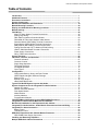
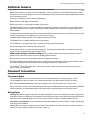
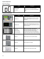
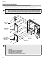
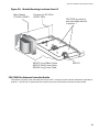
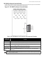
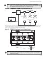
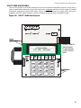
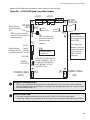
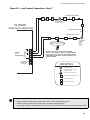
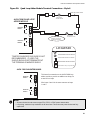
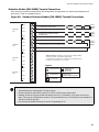
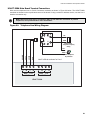
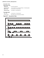
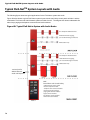
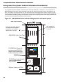
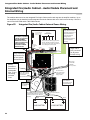
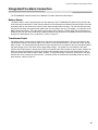
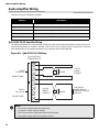
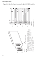
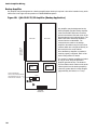
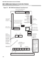
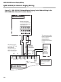
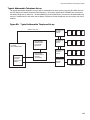
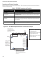
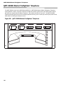
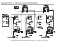
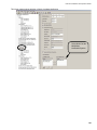
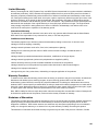
Field Wiring
Analog Loop Wiring
Figure 31: Loop Terminal Connections - Class B
TWISTED PAIRWIRE
S
S
S
F
Conventional Heat Sensors
and Manual Pull Stations
M
FX-2000N
MAIN FIRE ALARM BOARD
SO
2 Pair
Cs
M
Cs
Cs
Cs
TWO WIRES
F
LOOP 2
ANALOG
LOOP
CONNECTIONS
H
H
H
S
F
+
B
A
+
-
+
-
4-WIRE
RESETTABLE
SUPPLY
INDICATING
CIRCUIT
NAC 0
+
+
-
LEGEND
S
Addressable Smoke Detector
with Standard Analog Base
H
Addressable Thermal Sensor
with Standard Analog Base
Cs
Conventional Smoke Sensor
M
Addressable
Monitor Module
F
Addressable Manual
Pull Station
SO
Addressable Supvr.
Output Module
Combination
Horn/Strobe
End-Of-Line-Resistor
Notes:
• Terminal blocks are “depluggable” for ease of wiring.
• All power limited circuits must use type FPL, FPLR, or FPLP power limited cable.
• Loop wiring: maximum loop resistance is 40 ohms total. These lines are power limited and fully
supervised.
• Observe in and out polarity when using module and base isolators.
46