1
APPENDIX C – Gas Piping
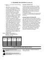
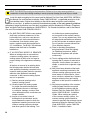
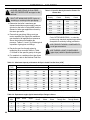
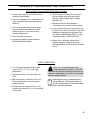
Table C-3: Specific Gravity Correction Factors For
Natural Gas
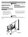
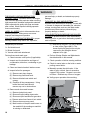
ASSURE GAS PIPING IS LEAK FREE
AND OF PROPER SIZE and type for the
connected load.
SHUT OFF MAIN GAS SUPPLY prior to
installing or servicing boiler gas piping.
Specific
Gravity
Correction
Factor
Specific
Gravity
Correction
Factor
0.50
1.10
0.85
0.81
0.55
1.04
0.90
0.82
0.60
1.00
1.00
0.78
0.65
0.96
1.10
0.74
0.70
0.93
1.20
0.71
0.75
0.90
1.30
0.68
0.80
0.87
1.40
0.66
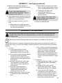
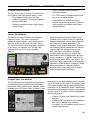
1.Determine the boiler’s maximum gas
demand and minimum gas supply pressure
(printed on the boiler’s rating label) and the
demand of other gas appliances served by
the same gas meter.
2. Ensure that gas piping, fittings, and gas
meter capacities can supply the maximum
gas demand of all appliances at pressures
above their minimum allowable gas
pressure. Tables C-1 and C-2 provide typical
capacities of gas pipes and fittings.
Code, NFPA54/ANSI Z223.1, or size the
system using standard engineering methods
acceptable to authority having jurisdiction.
USE PROPER THREAD COMPONENTS
on all gas connectors.
3. Derate the gas flow through pipes by
multiplying by a correction factor in Table
C-3 based on the specific gravity of the gas.
gas.
4. For materials or conditions other than those
USE THREAD (JOINT) COMPOUNDS
(pipe dope) rated for liquefied petroleum
listed above, refer to the National Fuel Gas
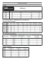
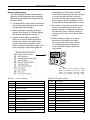
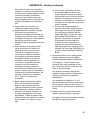
Table C-1: Maximum Capacity of Schedule 40 Pipe in Cubic Feet Per Hour (CFH)*
Length
(Feet)
½
10
132
0.3” w.c. Pressure Drop
¾
1
278
520
0.5” w.c. Pressure Drop
¾
1
1¼
½
1050
175
360
680
1400
1¼
20
92
190
350
730
120
250
465
950
30
73
152
285
590
97
200
375
770
40
63
130
245
500
82
170
320
660
50
56
115
215
440
73
151
285
580
60
50
105
195
400
66
138
260
530
70
46
96
180
370
61
125
240
490
80
43
90
170
350
57
118
220
460
90
40
84
160
320
53
110
205
430
100
38
79
150
305
50
103
195
400
*1 CFH of Natural Gas is approximately equal to 1000 BTU/hr; 1 CFH of LP is approximately equal to 2500 BTU/hr.
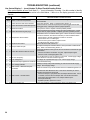
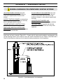
Table C-2: Equivalent Lengths (ft) Of Standard Pipe Fittings & Valves
40
Pipe
Size
Gate
Globe
Angle
Swing
Check
90°
Elbow
45°
Elbow
90° ‘T’, Flow
Through Run
90° ‘T’, Flow
Through Branch
½”
0
¾”
0
19
9
4
2
1
1
3
23
12
5
2
1
1
4
1”
1
29
15
7
3
1
2
5
1 ¼”
1
39
20
9
4
2
2
7
1 ½”
1
45
22
11
5
3
3
8