1
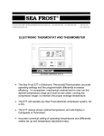
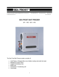
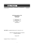
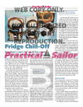
148 OLD CONCORD TURNPIKE, BARRINGTON NH 03825 USA
TEL (603) 868-5720
E-Mail:[email protected]
FAX (603) 868-1040
1-800-435-6708
www.seafrost.com
ELECTRONIC THERMOSTAT AND THERMOMETER
With SPEED CONTROL
•
The Sea Frost ETT (Electronic Thermostat/Thermometer) will accurately control
temperature for the best efficiency
•
The ETT always shows cabinet temperature, and will display in Centigrade or
Fahrenheit.
•
Non-volatile memory, control will not loose settings.
The ETT is pre-wired with plug in connectors for the two 10’ probes and 20’ data cable
included. Custom lengths are available.
Faceplate size: 4-5/8” x 3-½” (120 mm x 90 mm). Requires 2-½” (64 mm) clearance
behind mounting panel. Weight 1 lb (.4 kilo).
CLEANING
Do not use acetone or any solvent on the control panel, clean with a damp cloth and
mild detergent.
INSTALLATION AND OPERATION
Operation
The Sea Frost Electronic Thermostat and Thermometer with speed control (ETTsc) is
an electronic device using two probes installed in the refrigerated space. One probe is
sensing the cabinet temperature, which is displayed. The other probe controls the
compressor operation by measuring the temperature of a cold plate.
To operate the control, push the top of the rocker switch to turn on the temperature
readout. The display will light and the temperature will be displayed. To start the
compressor turn the speed control knob to desired position. There will be a slight delay
before the run light turns on.
Changing Speeds
Speed can be changed at any time. If the compressor is running when the speed is
changed, the red run light will go off and then will go back on when the compressor has
adjusted to the new speed.
Run Light
The run light indicates the compressor is operating. When the compressor cools to the
pre-set cut out temperature the run indicator light will go off with the compressor.
To display temperature only, turn the compressor speed control to the off position.
To turn off both the temperature readout and compressor the rocker switch may be
used. All temperature settings will be saved.
Error Light
The yellow error light indicates a compressor fault. See page 6.
THE TEMPERATURE SETTING
Before adjusting the thermostat make sure the refrigeration system is working properly.
The ETTsc can be adjusted and will maintain very stable temperatures. Care must be
taken to adjust the settings to maintain obtainable temperatures. In initial testing do not
2
set below -10 F. (–23 degrees C.) BDxpx models may be set lower - 20 F ( - 29 C.)
Excessive compressor running will occur with no benefit if the setting is below the
temperature the compressor system can easily obtain.
To check the cut out setting (cold stopping point) push and hold the SEL button until
ST1 appears. Release the button and a number will flash. This is the cut out
temperature. Push SEL again and the readout will return to box temperature. The cut
out temperature is associated with the second probe (red banded). This probe read out
temperature is hidden. Press and hold the down arrow button to view this read out
temperature.
Plate Probe Temperature
To monitor the cooling progress, push in and hold the down arrow button. The plate
probe temperature will be displayed while this button is held.
Recommended Settings
The air temperature in a refrigerator is always 10 to 15 degrees F. (6 to 9 C.) warmer
than the cooling device. This difference in temperature must be remembered when
setting the control cut out temperature (stopping point). A refrigerator might have to be
set to run up to 20 degrees colder than the desired box temperature.
Make several small setting changes over a period of several days to determine the
proper setting.
Changing the Temperature
To lower or raise the box temperature, hold the SEL button until the ST1 appears.
Release the button and the cut out temperature will flash. Use the up and down arrows
to change the temperature. Push SEL when finished. The control setting has now been
changed.
The Differential Setting
The differential is the number of degrees the temperature must rise before the
compressor will come back on after cooling to the set point. The factory test setting is 6
degrees F. (4.5 C.)
To change the differential setting press and hold PRG until P 1 is displayed, then press
SEL. Use the up and down arrows to change the setting. Press PRG when finished.
3
Readout Changes ~ Fahrenheit to Centigrade
To change the readout to centigrade hold down PRG and SEL for 5 seconds until 0 is
displayed. Using the up and down arrows select #77, which is the password. Press
SEL. Using the up and down arrows scroll to C-18. Press SEL. Using the arrows keys
set 0 for centigrade or 1 for Fahrenheit. Press PRG to store the change and return to
the temperature display. WARNING: When changing temperature measurement units
the cutoff setting and the differential setting must be changed to represent the proper
units.
INSTALLING THE ETTsc
The ETTsc can be located anywhere as long as it is protected from water and spray.
The leads to the probes may be extended to any length if the connections are soldered
and sealed with heat shrink.
The ETT sc requires a 3 5/8” x 2-¾” (91 mm x 70 mm) panel cut out. The minimum
depth is 2-½” (64 mm).
Wire Routing and Connecting
The blue cat-5 cable provides power and signal for the ETTsc. It connects at the
compressor. The RJ-45 connector on this cable plugs into the RJ-45 port on the
Module PCB board. Make certain the plug is clean, and that the plug has not been
damaged when routing through the boat, before plugging it in.
If shortening this cable make sure the color code is observed. Any pre-made RJ-45
cable will work. Custom lengths are available.
Fuse
Install a 3-amp ATC fuse in the fuse holder on the Module PCB board on the
compressor.
Wiring Connections
The two black probe wires must enter the refrigerated space. The probes plug into the
head unit cables. NOTE: One probe has a red band and should connect to the plug
with the red band on the back of the ETTsc head. The probe with the red band must be
routed to attach to the cold plate, if fitted with two cold plates the probe will attach to the
second plate. The second plate is the one without an expansion valve.
If you need to disconnect the plugs, do not pull on the wires insert a small screwdriver
blade between the halves of the plug.
4
PROBE ATTACHMENT
The probe with red bands must be in excellent thermal contact with
the cold plate. Use the stainless steel clip provided, and attach it to
the edge of the plate as shown in the drawing to the right.
The probe without a red band should be installed at the mid point of
the cabinet to get an accurate reading of the average temperature.
Avoid installing this probe near a front opening door or too close to a
cold plate. Mount the probe bulb with two nylon straps or self stick
pads and tie wraps provided. Do not drill and screw into a vacuum
panel box!
Secure the wires neatly using cable ties, self-stick pads, and proper
yacht construction wiring practices.
5
TROUBLESHOOTING
In case the electronic unit records an operational error, the fault diode will flash a
number of times. The number of flashes depends on what kind of operational error was
recorded. Each flash lasts 1/4 second. After the actual number of flashes there will be
a delay with no flashes, the sequence for each error recording is repeated every 4
seconds. Flashes will only occur in the fault mode with the system on.
OPERATIONAL ERRORS SHOWN BY YELLOW LED
Number of flashes
5
4
3
2
1
Error type
Thermal cut-out of electronic unit (If the refrigeration system has
been too heavily loaded, or if the ambient temperature is high, the
electronic unit will run too hot).
Minimum motor speed error (If the refrigeration system is too
heavily loaded, the motor cannot maintain minimum speed 1,850
rpm).
Motor start error (The system is overcharged).
Fan over-current cut-out (The fan is defective).
Battery protection cut-out (The voltage is outside the cut-out
setting. Low voltage.)
See: Separate BD/Tradewinds Trouble Shooting Data Pages on-line.
6
SEA FROST ELECTRONIC THERMOSTAT AND THERMOMETER
DRILL (4) HOLES 3/32" FOR #6 SCREWS.
(1)
(2)
(1)
Control Panel Head
Sensor Probes (1-with red band, 1-without red band)
Cat 5 cable with RJ 45 Connector
INSTALLATION KIT
(4) #6 x 1/2" flat head screws for mounting panel
(6) #6 x 1/2" pan head screws
(5) 3/16" nylon clamps
(8) Adhesive mounting tabs
(10) 4" tie wraps
(1) Stainless steel bulb clip
(1) Fuse
7