1
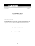
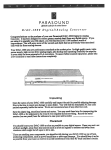
372 ROUTE 4 BARRINGTON, NH 03825 USA
TEL (603) 868-5720
FAX (603) 868-1040
E-Mail:[email protected]
1-800-435-6708
www.seafrost.com
DC 5000 SYSTEM 134a
OPERATION & INSTALLATION
INSTRUCTIONS
NOTICE OF RESPONSIBILITY
It is the SEA FROST/C.F. Horton & Co., Inc. intent to provide the safest, most accurate
and detailed instructions. SEA FROST/C.F. Horton & Co.,Inc. cannot be responsible for
problems or damage caused by omissions, inaccuracy or interpretation of these
instructions.
SEA FROST is a registered trademark of C.F. Horton & Co.,Inc
Aspects of the SEA FROST design are covered by
US Patent #4,356,708
2nd Edition
134 12 volt
Copyright © 1996 by C.F. Horton & Co., Inc.
1
START UP PROCEDURE AND PERIODIC INSPECTION
ATTENTION new SEA FROST owner or operator! PLEASE DO NOT
OPERATE THE REFRIGERATION SYSTEM UNTIL YOU READ THIS.
WARNING! Your SEA FROST System can be severely damaged and your warranty
will be invalid if these steps are not followed closely. Please read the information here
before proceeding to operate your system for the first time.
BREAK-IN PERIOD. LIMIT COMPRESSOR RUNNING TIMES TO THIRTY MINUTES
FOR THE FIRST TWO HOURS OF OPERATION. THIS SHOULD BE FOUR
SEPARATE THIRTY-MINUTE OPERATIONS WITH A REST PERIOD OF AN HOUR
OR MORE BETWEEN THEM.
1) Locate the SEA FROST Receiver/Filter/Drier (RFD). The location of this part varies
from boat to boat, but it is often found in the compartment with the DC 5000, in a locker,
or beneath the cabin sole. It is a blue metal can about 9 inches high and 3 inches in
diameter, with brass fittings connecting it to copper tubing. If you do not locate the RFD
quickly, follow the route of refrigeration copper tubing, from the DC 5000 to the icebox.
Along the route you will find the RFD. The RFD has a sight glass for viewing the flow of
refrigerant.
2) Check to be sure the proper sea cocks are open.
3) Start the DC 5000 by turning on the thermostat. The red indicator light should light,
indicating 12-volt power is available and that the system is operating. Check the
overboard discharge to be sure water is being pumped.
4) With the system running look at the sight glass in the RFD.
5) MONITOR THE SIGHT GLASS CONTINUALLY. White FOAM should appear in the
sight glass indicating that refrigerant is present. This foam may disappear quite quickly,
but IF NO FOAM IS EVIDENT, that is, if the sight glass does not show the presence of
refrigerant within a minute or two of operation the system is dead flat. DO NOT
CONTINUE TO OPERATE THE SYSTEM. OPERATION IN THIS MODE WILL RUIN
THE COMPRESSOR. Switch off the DC 5000 to prevent operation until the problem is
corrected. CALL US AT 603-868-5720.
6) If white foam is evident watch closely for a transition from foam to clear: a clear
sight glass indicates a sufficiently charged system. This point can be missed if proper
attention is not given. A FULL SIGHT GLASS AND AN EMPTY GLASS LOOK THE
SAME! It is possible for the sight glass to show large, almost stationary bubbles even
when the charge is sufficient, so it is important to differentiate between "foam" and
larger “bubbles”. The foam condition has velocity and direction, but the larger
bubbles are nearly stationary. If the foam does not clear, the system is low on
charge. CALL US AT 603-868-5720 for trouble shooting and correction help.
2
There are three conditions of charge indicated by the sight glass:
1. A black or clear glass and no cooling indicates no charge. Turn off the
compressor at once.
2. A white foaming glass and some cooling indicates the system is undercharged or
has lost charge. Refer to the manual regarding leak checking and adding
charge.
3. A black glass and proper cooling indicates all is well.
RFD SIGHT GLASS DETAIL
EMPTY OR CLEAR
STATIONARY BUBBLES
FOAM/LOW
Feel the SEA FROST Plate in the icebox ten minutes after engaging the timer switch. If
the sight glass clears yet the plate temperature does not drop after 10 minutes of
operation, turn off the system and CALL US AT 603-868-5720.
Inspecting the sight glass periodically for several weeks after a new installation and
every time after a lay period is assurance that your SEA FROST DC 5000 system is
assembled properly and is a good maintenance habit as well.
3
TABLE OF CONTENTS
OPERATION
GENERAL DESCRIPTION
ICE MAKING
MAINTENANCE
HOW REFRIGERATION WORKS
INSTALLATION
COMPRESSOR INSTALLATION
WATER PUMP
PLATES
VALVE UNIT
SWAGELOK FITTINGS, MAKE-UP & RECONNECTING
RECEIVER FILTER DRYER
ELECTRICAL SYSTEM; WIRING; THERMOSTAT CONTROL PANEL
WIRING DIAGRAM
ASSEMBLY INSPECTION CHECK LIST
REFRIGERANT HANDLING
ACCESS TO THE SYSTEM: SERVICE PORTS
GAUGES
LEAK CHECKING
NEW SYSTEM CHARGING
READING THE SIGHT GLASS
PROPER CHARGE AMOUNT: MAXIMUM CHARGE
DISCHARGING THE SYSTEM
TROUBLE SHOOTING
PRESSURE CHARTS
DC5000 MOTOR MAINTENANCE
DRAWINGS
VOLTAGE MONITORING RELAY WIRING
4
5
5
7
7-8
8-9
9
11
12
13
13
14-16
18-19
20
21-22
23
23-24
25
25-26
28-29
28
31
32
33
33-34
37-38
39-40
42-45
46
GENERAL DESCRIPTION
The SEA FROST DC 5000 is a cold storage refrigeration system powered by a 1/2
horsepower permanent magnet direct current 12-volt motor. Refrigerant from the
compressor is piped to the SEA FROST plate in the icebox. Cold storage is attained by
rapidly freezing the solution contained in the plate, creating a captive (replenishable)
block of ice. The system may be used when the boat’s engine is on and charging the
batteries or with a properly sized battery bank. The compressor may be controlled by
an oil pressure switch preventing operation without the engine, a lockout relay that
prevents operation without the shore power charger operating, a timer, or by a
thermostat alone. The heat removed from the icebox is discharged into the seawater at
the water-cooled heat exchanger. A separate pump below the water line controlled by
the DC 5000 pumps water through the heat exchanger and overboard above the water
line.
BREAK-IN PERIOD.
REFER TO THE START UP PROCEDURE IN THE BEGINNING OF THIS MANUAL.
EVERY TIME THE SYSTEM IS RESTARTED FROM WARM, CHECK TO BE SURE IT
IS COOLING BEFORE OPERATING THE COMPRESSOR EXTENSIVELY. THIS IS
YOUR SYSTEM. SIMPLE OBSERVATIONS OF YOUR SYSTEM AND OPERATING
CAUTION WILL PREVENT DAMAGE THAT COULD COST YOU MONEY.
OPERATION
1. This system is water-cooled and depends on water being pumped by the remote
DC 5000 pump. The proper sea cock must be open before starting the
system. Water flow is most important, therefore CHECK THE WATER FLOW
AFTER STARTING THE SYSTEM.
2. Check the battery switch position and voltage readings before starting.
3. Start the DC 5000 by turning on the thermostat. The red indicator light should
light, indicating 12-volt power is available and that the system is operating.
Check the overboard discharge to be sure water is being pumped.
4. If the battery system is fitted with an amp/hr meter you will notice the DC 5000
compressor drawing about 45 amps/hr (12 volts) for the first few minutes
dropping to 35 amps/hr for the remainder of the cycle.
5. After 10 minutes of operation, check for a drop in the cold plate temperature by
feeling the plate with your hand. If no noticeable cooling has occurred, turn off
the thermostat. Check the charge level (See checking the refrigerant charge
section) and check the water flow. TO PROTECT THE COMPRESSOR, DO
NOT OPERATE the system if this temperature drop is not noted. CALL US AT
603-868-5720.
5
After about one hour (with a single plate), the plate will become very cold. Starting from
warm will require more running than the normal refreezing time of the plate in its usable
temperature range.
The concept of the SEA FROST system is to create as much frozen material in the plate
as fast as possible. This "coldness" then keeps the cabinet cold. Daily running times
are based on the time needed to freeze enough of the plate to maintain proper cooling.
The plate must be frozen. Chilling the plate without freezing it will not provide any
holdover. You will learn about the daily time required for SEA FROST operation by
using the system.
Note: Maximum holdover time will be obtained when the cabinet and contents are at
their lowest temperatures and the plate is frozen solid. There is no limit to "on" time
however, no advantage is gained by running the system beyond this point and in
refrigeration applications over running will freeze items. Over running will also produce
undue wear on the motor, compressor and pump.
Cabinet size, cabinet insulation, contents added to be cooled, cabinet opening and
closing, and climate effect the holdover time.
SUGGESTIONS
As soon as the system has stopped the plate will begin to warm up as it absorbs heat,
cooling the refrigerated box. You might decide that it is a good idea to run the unit in
the last minutes of the day to provide ice for drinks.
Maximum storage will require that the plate be frozen. The plate may thaw (be above
freezing) and still not require running in refrigeration applications. Monitor the box
temperature itself not the plate temperature.
For minimum battery consumption set the thermostat at the highest (warmest) possible
setting. This would be toward one snowflake. When the engine or generator are
operating and charging, operate the DC 5000 at the maximum (coldest) setting to
increase the holdover storage and minimize battery consumption by freezing the plates
solid.
With timer operated systems two shorter periods a day may be better than a long one
once a day. When the holdover freezing is complete the benefit of running is only to
delay warming. There is some help in that cooling of the contents of the box will
increase holdover time but heat, "cold", moves slowly and it will be more efficient to wait
and run again later. Experimentation will provide the best instruction on how the SEA
FROST DC 5000 should be operated on your boat.
DEFROSTING will be required. A heavy layer of frost or ice will reduce cooling. This is
very important in freezers.
6
ICE MAKING
WITH VERTICAL TRAYS ON VERTICAL PLATE SYSTEMS
Fill the vertical trays with water and hang them on the stainless steel rod on the face of
the plate. Try to get some water between the tray and the plate surface to increase the
thermal contact to speed freezing.
The trays may take time to freeze after the plate is frozen and the compressor has been
switched off.
HARVESTING VERTICAL TRAYS
Plan to wait for the trays to thaw in a sink or away from the plate in the refrigerator.
When the outside surface is wet invert the tray and let the ice slide out.
STORAGE OF ICE CUBES
After ice has been made and harvested, store it in sealable plastic bags in the
refrigerator or freezer. Leaving the ice in trays in contact with the plate will allow the ice
to melt if the plate goes above freezing.
MAINTENANCE
Like your engine, your SEA FROST needs periodic checking.
ROUTINELY CHECK:
1. The refrigerant charge. (See Start Up Procedure text) NEVER OPERATE
SYSTEM WITHOUT PROPER CHARGE.
2. All components, bilge and engine room fittings for corrosion and wear. BE SURE
TO LOCATE AND INSPECT ALL FITTINGS AND COMPONENTS IN THE
SYSTEM. KNOW THE LOCATION OF ALL CONNECTION POINTS. Spray with
a rust inhibitor REGULARLY. Corrosion unchecked in the marine environment
will severely reduce the life of your system.
3. Motor maintenance. Brush wear must be checked at early intervals to determine
future required inspection. Failure to inspect and replace brushes when
needed will ruin your motor. See: Motor & pump maintenance, pages 3940.
4. Winter storage will require that the water pump and water-cooled condenser be
drained or flushed and filled with antifreeze solution to avoid freeze damage. If
the condenser is to be left dry flushing with a large amount of fresh water to
remove salt deposits is recommended. (The pump will not self-prime. It might
be necessary to install a hose and funnel on the intake to force-feed the pump.)
7
CLEANING
The plate surface protects itself with a layer of oxidation. You might find after a long
period of storage the plate will look chalky. This will not effect operation and is easily
cleaned up with a pot scrubber and soap.
HOW REFRIGERATION WORKS
There are two important concepts to understand in order to learn about refrigeration.
They are latent heat and phase changes.
A great deal of heat is required to change a solid to a liquid, and a liquid to a vapor. A
great deal of heat must be removed to reverse these changes. These changes are
called phase changes, or changes of state. The heat removed or added at these phase
changes has no effect on the temperature of the substances until the change is
complete. For instance, ice melts at 32 degrees F. Water freezes at 32 degrees F. Ice
and water will remain at 32 degrees F. until the freezing or melting process is complete.
Latent heat is this hidden energy required to make or break the bonds in a phase
change.
By evaporating liquid to a vapor, we can absorb heat. By condensing a vapor to a
liquid, we give up heat. Refrigeration is the use of these phase changes to move heat
out of the icebox (cooling it). We all know that cold is the absence of heat. A practical
example of heat absorption by evaporation is rubbing alcohol evaporates in your hand
and cools it. The alcohol is actually using the heat from your hand to boil. The
absorption of heat cools your hand.
Pressure affects the temperature at which a vapor phase change will occur. Using
water as an example, water boils at sea level at 212.F. On top of Mt. Everest it boils at
a much lower temperature. The air pressure is lower allowing the water-to-steam phase
change to occur more easily. A pressure cooker increases the pressure on water to
restrict boiling to a higher temperature. A pressure cooker will cook food faster because
the temperature is higher. Remember that a phase change involves latent heat. The
temperature of boiling water is only 212.F at sea level. The evaporation action is
absorbing heat at a rate equal to the rate of heat applied, preventing further temperature
rise.
Let's look at Refrigerant-134a. R-134a will boil at minus 15 degrees F. at sea level. By
evaporating liquid R-134a in the SEA FROST plate, heat is absorbed making refrigerant
vapor. To dispose of this heat, a condensing phase change is necessary. By
increasing the pressure (compressing) we can raise the boiling point of the refrigerant
vapor at the condenser. Seawater passing the condenser coils removes the heat,
forcing the vapor to a liquid state again. Pressure, therefore, is the key that allows
passing the heat we have taken from the icebox to a warmer place (the sea water) and
converting the vapor to liquid to be evaporated again.
8
By causing R-134a to boil (evaporate) in the SEA FROST plate, we use the heat
energy there. This activity cools the liquid solution within the plate, causing it to change
phase (freezing to a solid). By freezing this solution, we have increased its heat
absorption capacity more than 100 times. When the cycle is stopped (the compressor
is turned off) the frozen plate will begin to absorb the heat that leaks through the
insulation in the icebox. The absorption will be at a constant temperature until the
phase change to liquid (melting) is complete. This is the principle of holdover
refrigeration and the function of your SEA FROST.
INSTALLATION ~ WORK HABITS
Installer's care should be stressed. No matter how good SEA FROST equipment is, it's
performance and life are in the hands of the installer. To insure your work:
1.
2.
3.
4.
5.
6.
Read this manual.
Reread any aspect you don't understand.
Follow Swagelok fitting instructions carefully.
Install the RFD last and the same day the system is charged.
Spend enough time leak checking to be sure there are no leaks.
Thanks from all of us who have to guarantee your work.
There are two contaminants that will give you problems in a refrigeration system. They
are WATER and DIRT. Moisture in the air is always present and cannot be eliminated;
water in this case refers to puddles and drops. Dirt is any solid. The installer's habits
will be most important in ensuring a trouble-free start-up. We have added a large
receiver filter drier (RFD) to take care of all dirt and moisture that might get into the
system during a careful installation. Moisture in the system is boiled off when the
system is evacuated, or it is captured in the desiccant. There is a screen in the
expansion valve to prevent dirt from plugging it.
Excess moisture that the RFD can't handle will plug the expansion valve with ice. This
ice stops the cycle. The only cure is to discharge the refrigerant, replace the RFD,
evacuate the system, and recharge it. This remedy takes time and is somewhat costly.
Keep the system clean and dry!
TUBE HANDLING
Installation is quite simple. All the copper tube comes to you with the ends capped.
Any routing of the tubing must be done with the tube either taped or capped. Cap both
tube ends after each cut. Work with only one line at a time, and uncap only one end at
a time.
9
TUBE CUTTING
Use only a tube cutter; hacksawing or any other method will introduce chips to the
system and also distort the tube, making connections difficult and leak-prone. A
miniature cutter is essential for this work. CUT SLOWLY to avoid a ridge on the inside
of the tube. We do not recommend reaming or dressing the cut, as it is very easy to get
chips of copper in the system that will cause trouble.
TUBE BENDING
Make all but the long sweep bends with a spring bender; one kink and the line must be
rerun. Don't add any more fittings than are absolutely necessary. Route all the lines in
such a way that they are most direct but out of the way. Always leave several inches of
straight undistorted tubing leading to all Swagelok fittings to allow proper connection.
Again, keep everything sealed until you are ready to make that connection.
FIT RFD LAST
The RFD (receiver, filter, drier) should be the last component to be unpacked and fitted.
INSTALLING THE DC 5000 COMPRESSOR UNIT
Install the DC 5000 in a dry location where the convergence of wires, water hoses and
tubing to the refrigerator area are the most convenient. Avoid installing the DC 5000 on
10
a bulkhead that directly separates the living space from the machine space to avoid
excessive sound radiation.
The DC 5000 may be installed close to a bulkhead and overhead. Allow access to the
front (as shown in the drawing above) and left end where the tubes and hoses will exit.
Fasten the DC 5000 through the (4) drilled holes in the base.
THE BRUSHES WILL REQUIRE PERIODIC INSPECTION AND REPLACEMENT. BE
SURE THE DC 5000 IS LOCATED WHERE BOTH BRUSH COVERS CAN BE
ACCESSED.
WATER PUMP INSTALLATION AND WATER CIRCUIT
Proper water pump installation is essential to a trouble free system.
• The pump will not self-prime.
• The pump must be well below the water line on all angles of heel.
• The pump motor must be above the pump body.
• The pump outlet must be above the pump inlet.
• The pump should have it's own intake through hull with sea cock, sea
strainer and exit through hull.
11
Install the intake through hull as low in the boat as possible. The minimum size through
hull should be 1/2". In areas of floating weed and jelly fish a larger through hull might be
beneficial. The sea strainer should be positioned above the through hull with no loops
of hose that could trap air. The pump should be positioned above the strainer and
pump up to the DC 5000. The water hose from the DC 5000 should leave the
condenser and descend or remain parallel to the water line exiting a through hull above
the water line.
ABOUT THE PUMP
The March 809 BR pumps are not self-priming. The coupling between the impeller and
the motor is through a pair of magnets. The impeller is water lubricated and does not
touch the housing in proper operation. The advantage of this pump is a long life, quiet
operation and low power consumption. To treat this pump properly it must be flooded at
all times. Air pockets created by rising and falling hose levels and an improperly located
pump and strainer will trap air, which the pump will not be able to displace preventing
water pumping. The only acceptable installation will not have air pockets in the water
circuit.
PLATE LOCATION
The plate size, location, and plumbing are designed for each application. This
information is provided with each system.
SEA FROST holdover plates mount with
a "Wellnut" expandable neoprene blind
hole fastener. A template or the plate
itself should be used to locate the
mounting holes. Drill 1/4" pilot holes
then increase them to 1/2". Install the
screw into the mounting tab then screw
the Wellnut onto the screw. Install the
plate pushing the rubber mounts into the
pre-drilled holes. Tighten the screws.
12
VALVE UNIT V/U
For appearance and convenience of installation, the valve unit may be mounted outside
the icebox. In certain applications and multiple plate systems it may be best to mount it
inside. Location of the V/U in multiple plate systems is indicated in the design layout
from our application engineer.
On an externally mounted V/U two 1/2" Swagelok fittings fasten the V/U to tubing
protruding through the icebox wall. Before cutting the tubing:
• Leave a minimum of 1 1/4" of tube beyond the bulkhead.
• Allow room for wrench access.
On any installation:
• The Valve Unit may be mounted in any position.
• 90-degree elbows can be factory installed on the Valve Unit to reduce the space
requirements if necessary.
• The tubing will support the Valve Unit.
• The tubing must bottom in the fitting. For final installation of this unit see the
Swagelok text.
• The V/U will attract moisture. If it is mounted externally to the cabinet be sure it is
accessible for proper insulation installation after the system has been leak
checked and operationally tested.
NOTES ON SWAGELOK FITTINGS
Swagelok fittings come to you completely assembled, finger-tight. (Pieces a, b, and c in
Drawing #1 are already together). They are ready for immediate use.
Disassembly before use can result in dirt and foreign material getting into the fitting and
causing leaks. If disassembly is necessary, reassemble per drawing.
This is a double ferrule system. The most serious installation problem encountered with
SEA FROST is the incorrect assembly of these fittings. Be absolutely sure that you
assemble all fittings as in Drawing #1.
To ease assembly slacken the fitting nut slightly before assembly. Then tighten with
fingers before tightening with a wrench. (This is to avoid cross threading.)
Step 1. Always leave two inches of straight, undistorted tubing leading to all Swagelok
fittings to allow proper connection.
13
Step 2. Prior to inserting 1/2" tubing into the Swagelok tube fitting, make a pencil mark
1" from end of tube. Prior to inserting 3/8" tubing, make a pencil mark 3/4" from the end
of the tube. With 1/4" tubing make a mark 5/8" from the end.
Step 3. Insert clean, smooth tubing with the pencil mark into the Swagelok tube fitting.
You can be sure the tube is resting firmly on the shoulder of the fitting when the pencil
mark is flush with the nut. This mark will also indicate that the tube has not moved
before tightening. (As the fitting is tightened the space from the pencil mark to the
shoulder will increase.)
Step 4. Tighten the Swagelok nut to a wrench snug* position. Scribe the nut with a
pencil at the 6:00 o'clock position (see drawing #1, step # 2).
* Wrench snug is the first point in the assembly tightening when the tube cannot be
pulled from the fitting, (i.e. when the ferrules tighten enough to contact the tubing).
Step 5. Now, while holding the fitting body with a back-up wrench, tighten the nut oneand-one-quarter turns (1+1/4). To do so, watch the scribe mark, make one complete
revolution, and continue to the 9:00 o'clock position. (See drawing #1, step #3).
DRAWING 1
STEP 1
Simply insert the tubing into the SWAGELOK tube fitting.
Make sure that the tubing rest firmly on the shoulder
of the fitting and that the nut is wrench snug.
14
STEP 2
Before tightening the SWAGELOK nut, scribe the
nut at the six o'clock position.
STEP 3
Now, while holding the fitting body steady with a backup wrench, tighten the nut 1 1/4
turns. Watch the scribe mark, make one complete revolution and continue to the 9
o'clock position. By scribing the nut
at the 6 o'clock position as it appears
to you, there will be no doubt as to
the starting position. When tightened
1 1/4 turns to the 9 o'clock position,
you can easily see that the fitting has
been properly installed.
* SWAGELOK FITTINGS ARE TO
BE TIGHTENED TO A TORQUE SPECIFICATION NOT INFINITE TIGHTNESS. BE
SURE YOUR STARTING POINT IS WRENCH SNUG. A DISTORTED TUBE MIGHT
GIVE A FALSE STARTING POINT.
* When making all connections, USE TWO WRENCHES. Don't allow the fittings to turn
or twist when tightening.
* Be sure the fitting nut is not cross threaded! Cross threading will ruin the fitting. The
fittings on the V/U cannot be replaced; as a result cross threading will ruin the V/U.
RECONNECTING PRE-SWAGED FITTINGS
Connections can be disconnected and re tightened many times.
When reconnecting, insert the tubing with pre-swaged ferrules into the fitting until the
front ferrule seats in the fitting. Tighten the nut by hand to avoid cross threading.
Rotate the nut about one-quarter turn with a wrench (or to original one-and-one-quarter
tight position). Then snug slightly with the wrench.
15
SWAGELOK PERFORMANCE
Swagelok fittings have built-in spring interaction between the ferrules. This
compensates for temperature changes, vibration loosening and allows the fittings to be
reconnected many times. As the fitting is tightened, a burnishing occurs between the
body of the fitting and the ferrules and between the ferrules and the tube. This action
provides a leak proof connection.
RUNNING THE LINES
See the schematic diagram. Prior to making up connections see "Swagelok Fittings"
texts.
16
PLANNING
1. Keep tube runs as short as possible. The suction (return) line should be as direct
as possible with a minimum number of bends.
2. Tape the 1/4" line and the 1/2" line together in the section between the V/U and
the DC 5000. This is for thermal exchange (sub cooling).
POSITIONING THE RFD
• The RFD is fitted with a sight glass. This glass must be visible for charging
and servicing the system. It can be viewed from the top at up to a 45-degree
angle but not from the bottom or side. A mirror installed above the glass is one
way of saving a poorly planned installation. Avoid this if possible. Be sure the
sight glass is easily visible!
• Observe the inlet/outlet on RFD when mounting it. The glass is offset toward the
outlet.
• The RFD should be unpacked and installed only after all the lines are run and all
other fittings are made.
HELPFUL TOOLS
• Coil spring-type tube benders are available for 3/8"-1/2" O.D. tube. These springs
are slid over the tube. The bend is formed in the spring, and then the spring is
removed by unscrewing.
• Lever benders for each size tube. Lever benders will make the tightest possible
bend without distorting the tube.
• Mini tube cutter: "IMP" by Gould Imperial requires less than 1 1/2" radius
clearance for the cut. This is essential to trim the plate tubes.
LINE CONNECTION PLAN
Run 1/4" copper tube from the DC 5000 to the RFD. From the RFD 1/4" copper tube
continues to the V/U. Run 1/2" copper tube from the large connection on the V/U to the
DC 5000. The two lines should be combined with tape and insulated together. See
Insulating the Lines.
17
RFD (Receiver Filter Drier)
DO NOT OPEN THE RFD UNTIL ALL THE OTHER CONNECTIONS HAVE BEEN
MADE AND YOU ARE READY TO COMMISSION THE SYSTEM. Because the RFD
contains desiccant to absorb moisture and the absorption is limited, it is important to
unpack and install it after all other connections are made. Leaving the RFD installed on
a partially open system may reduce its capacity by allowing it to absorb moisture in free
air before the system is sealed.
The RFD is a reservoir for excess refrigerant. The RFD also
contains a sight glass in the top. (Please refer to the planning
section regarding location and "readability" of the sight glass)
A pick-up tube extends from the bottom of the canister to the
outlet. For proper function of the reservoir, the RFD must be
VERTICAL to ensure proper operation at various heel angles.
MOUNTING THE RFD
The inlet is from the DC 5000. (The sight glass is offset on the RFD toward the outlet.)
The RFD is to be mounted with the bracket and mounting strap. Cable ties with screw
mounts should be used to support the tubing.
INSULATING THE LINES
Insulating should be the last step after leak testing because it will cover fittings that must
be leak-checked. On long uninterrupted lengths of tubing, the insulation can be slipped
over the tube early. Insulation should be installed only on dry lines, and only after the
acrylic spray is applied to all metal parts. The suction return line is cold and will attract
moisture (as frost) when running. The suction return line includes all the exposed 1/2"
tubing and the larger fittings. The entire V/U will also frost. It is important to insulate the
1/2" line, the V/U and all the fittings along the line to prevent moisture from gathering.
INSTALL THE INSULATION IN A MANNER THAT WILL NOT TRAP WATER AROUND
A LOW POINT. Trapping salty bilge water in the insulation will reduce the operating life
of tubing and fittings. If the insulation is split and wrapped over the tube, install it with
the split side down. Tubing within the icebox need not be insulated.
18
CABLE TIES
Cable Ties should be used to support the wiring, tubing, and insulation. There is a
screw hole in the end of each tie that is used for mounting. Loosely loop the tie, mount
the screw loosely, snug the wrap, tighten the screw, and trim the excess. Be sure not
to leave a sharp end on the cable tie.
ELECTRICAL SYSTEM
The electrical system for the DC 5000 system includes a Thermostat Control Panel with
pilot light, and a junction box with solenoid.
19
THERMOSTAT CONTROL PANEL LOCATION
The Thermostat Control Panel should be outside the box in order to protect it and to
allow observation of the indicator lamp. The length of the sensing tube dictates the
location, as it must reach the plate. The maximum length of this tube is 40" (180 mm.)
(The sensing tube must be attached to the refrigerator plate in a multiple plate system.)
Mount the Thermostat in a location where the wires and sensing tube can be led. Use
the cut out template packed with the Thermostat Control Panel. The harness on the
Thermostat Control Panel may be spliced with 16-gauge wire.
ELECTRICAL JUNCTION BOX
The DC 5000 is equipped with a 4' (105 cm.) harness that is to connect to the Electrical
Junction Box. Do not splice this harness. Position the Electrical Junction Box to
allow proper routing of the harness. If the electrical junction box is closer than 4 feet,
shorten the harness.
Large battery supply cables, (See wire sizes) the thermostat control harness, and water
pump harness will all connect at the electrical junction box.
20
WIRE SIZES
This information is to be used as a guide only. Please make sure your wiring meets or
exceeds all applicable standards.
The DC 5000 must be wired with heavy gauge wire from the batteries to the Electrical
Junction Box in order to supply the proper current and voltage. Follow the chart below
based on the ABYC specifications allowing a 10% voltage drop. If possible use the next
larger size. These distances are from the batteries to the Electrical Junction Box.
10 gauge less than 10 feet
8 gauge less than 15 feet
At a minimum use:
6 gauge less than 25 feet
4 gauge less than 40 feet
21
The positive and negative cable total length must not exceed twice the distance
listed above.
Be sure your wire length calculation is from the batteries not the connection points
of the supply wires. (It is assumed that heavier cable is used to supply an electrical
junction like the battery switch or buss bar.)
FUSES
Fuse the 12-volt positive wire from the battery to the Electrical Junction Box with a 50amp fuse. The fuse location should be as close as possible to the battery or selector
switch. (Refer to ABYC standards) If a breaker is used it must be rated for 75 amps @
12 volts.
WIRING
The best installation should have the shortest possible conductor lengths connecting the
batteries and the Electrical Junction Box.
Do not feed the DC 5000 from the boats 12-volt breaker panel.
Voltage drop and power loss can occur through the supply wires, terminal ends,
and switching devices.
An in line fuse can act as a service disconnect.
Wires should be kept out of the bilge and wet areas.
Secure wires every 18 " with nylon tie-wraps or non metallic clamps.
GROUND WIRE
Connect the ground lug to the engine negative boat ground with a green 8-gauge wire.
ASSEMBLY INSPECTION CHECK LIST
[
] 1. Check accessibility of brush covers for service.
[
] 2. Check that the RFD sight glass can be seen.
[
] 3. Check all the Swagelok connections with wrenches to be sure they have been
made up. Refresh your knowledge by rereading the Swagelok instructions.
22
[
] 4. Check all the hose clamps for tightness.
[
] 5. Check the neatness of the installation, sufficient service access, secure wiring,
and make sure tubing and hoses are supported to prevent damage and chafing.
[
] 6. Check the service access. The service access ports must allow
attachment of the connecting service valves.
[
] 7. Check (after leak checking and testing) that the tubing is properly insulated.
REFRIGERANT HANDLING AND SAFETY
Do not proceed if you do not fully understand the procedure and know what results to
expect. Understand that pressure exists in refrigeration systems. Be careful.
DISCLAIMER
The gauges, adapters, hoses and tools described in this manual are available from Sea
Frost. We are not familiar with all equipment and cannot be sure we are covering
procedures that can be preformed without the same equipment. Be certain you
understand what you are doing and how each valve, check valve, can tap, adapter, and
gauge set works before connecting to a charged system or a refrigerant supply.
REFRIGERANT
The SEA FROST DC 5000 is charged with REFRIGERANT 134a. R-134a is a chemical
compound called tetrafloroethane. It is odorless. Its boiling point is -15. degrees F. at
sea level. It is heavier than air. It's label and container color is light blue. R-134a is
used in auto air conditioning systems and should be available in auto parts stores.
GENERAL SAFETY THIS IS IMPORTANT. READ THIS!
R-134a is safe if handled properly. Avoid breathing vapors and prolonged skin
exposure. Avoid using in areas of open flames. The vapor is heavier than air and may
reduce oxygen available for breathing. Use with sufficient ventilation to keep exposure
below recommended limits. Do not mix with air for leak testing or use with air for
any purpose above atmospheric pressure. Liquid R-134a will freeze skin. It's
especially dangerous to the irreparable tissues of the eyes.
--WEAR EYE PROTECTION-Do not pressurize an empty system with R-134a without first evacuating the
system with a vacuum pump.
23
WARNING NEVER OPERATE a system WITH THE HIGH side (discharge) OPEN TO
the REFRIGERANT supply. Pressurization of the refrigerant container could cause it to
burst.
WARNING. When charging or working on the system installed in an engine room with
the engine running, watch for MOVING BELTS AND PULLEYS. Loose clothes and long
hair can pull you into a belt. PLEASE BE CAREFUL.
PROCEDURES FOR WORKING WITH R-134a
1) A new uncharged system must be evacuated before adding R-134a.
2) An R-134a system must only be pressurized with R-134a or nitrogen.
3) Only service tools dedicated to R-134a are to be used. No parts, tubing, fittings,
receivers, driers, service gauges, or any refrigerant carrying components may be fitted
to a R-134a system from a used system or from a CFC based system. Damage caused
by the use of parts not supplied by Sea Frost for a R-134a system will cancel all claims
against Sea Frost.
4) No oil is to be added to the DC 5000 system but the PAG oil supplied by Sea Frost,
labeled and capped for DC 5000 use. No oil is to be added to a system with out prior
consultation with Sea Frost.
5) The oils used in R-134a systems are extremely moisture sensitive (hydroscopic). Do
not leave any tube end or component connection open to air while assembling the
system. Be sure to use only new-capped copper tubing and be sure to cap the copper
coil after cutting it.
ACCESS TO THE SYSTEM: SERVICE ACCESS PORTS
The access ports are two small capped valves mounted on the tubing on the top of the
DC 5000. The ports are of different sizes. The large fitting is the discharge port and is
connected to the 3/8" diameter tube. The smaller fitting is the suction port and is
connected to the 1/2" diameter tube. These ports are the service access to the system.
To access these ports the proper connecting valve must be used. (See Gauges)
Be sure the plastic port caps are installed tightly after charging or service. The
caps are to seal the ports. Without the caps the ports may leak.
24
GAUGES
Gauges must be used in the evacuation and charging. They will provide information on
the operation of the system when troubleshooting.
A gauge sets consist of two gauges installed in a manifold with two hand wheel valves
and hoses to connect the gauges to the system. The left gauge (blue) is a compound
device; it indicates pressure and also vacuum. The right gauge (red) indicates pressure
only. The hand wheels open a center port (yellow) to the left or right side respectively.
Operation of the hand wheels is only necessary when moving refrigerant or evacuating.
With the hand wheels closed, the gauges read the pressures of the connection points.
At the end of the red and blue service hoses are R-134a connecting valves. At the end
of the yellow hose is a self-sealing check valve that will only open when attached to a
fitting.
Keep your gauges clean. Inspect the rubber gaskets and "o" rings on the hose ends.
Leak-check the gauge valve packing and all hose connections. Check and reset the
"O" (zero) on the low side gauge while open to atmospheric pressure, if necessary.
R-134a SERVICE CONNECTING VALVES
The R-134a connecting valves on the gauge hose ends are quick connect fittings with a
specially designed valve that when turned opens and closes the hose end while
opening and closing the access service port.
25
CONNECTING GAUGES
To connect service gauges to the access service ports, remove the protective sealing
caps from the service ports on the DC 5000. Note that the ports are of different sizes.
The larger diameter port is the discharge side and the smaller port is the suction side.
Pull back the collar on the connecting valve and push it over the appropriate access
port.
IMPORTANT: There may be a variation in the interface (depending on the brand of
service valve being used) between the connecting valve and the service port core valve.
It is important to open each connecting valve carefully. Do not force the connecting
valve or turn it to it's stop. Forcing the connecting valve will bend the service port
core valve creating a leak.
Turn the connecting valve clockwise to open. During the service operation these
valves are left open. Control of refrigerant and vacuum is by the manifold hand
wheels.
TO INSTALL GAUGES ON AN UNCHARGED SYSTEM to be evacuated no purging or
venting is needed.
TO INSTALL GAUGES ON A CHARGED SYSTEM, with the system off, attach the
connecting valves to the service ports. Proceed to Venting the Gauge Set.
DISCONNECTING GAUGES
Disconnecting the gauge set after running the system may be done by turning off the
discharge connecting valve first. Remove the connecting valve and re-cap the access
service port. Turn off the refrigerant supply. Be sure the end of the yellow center hose
is closed. Both hand wheels on the gauge set may now be opened and the compressor
operated to extract the refrigerant from the gauges. When the pressure in both gauges
drops to the low side operating pressure turn off the hand wheels and the connecting
valve. Turn off the compressor. Remove the remaining connecting valve and re-cap the
access service port.
Disconnecting the gauge set on a static system may be done by turning off the
connecting valves and disconnecting them from the access service ports. Re-cap the
access service ports.
26
VENTING THE GAUGE SET
To connect the gauges to a charged system if the gauge set has not been purged with
refrigerant, attach the service valves to the system and vent the hoses at the manifold
body by opening the hand wheels to an open center hose for a few seconds allowing
some of the system refrigerant to purge the hoses of air. If the center hose is fitted with
a check valve it will not be purged and must be purged with the refrigerant supply before
introducing charge.
TAPPING A CAN OF REFRIGERANT
Be sure the can of R-134a is clean and dry. Any contaminants on the top of the can or
in the hose will enter the system. Turn the can tap valve counterclockwise to retract the
piercing point. Thread the valve body on to the can. Be sure the rubber gasket is
seated. Next, screw the valve into the valve body, closing the valve, piercing the can.
Opening and closing the valve will now regulate the refrigerant flow from the can.
VENTING THE CHARGE HOSE
To avoid pulling air or other contaminants into the system, it is necessary to vent the air
from the hose that is used to carry R-134a to the system. To vent the hose, open the
can tap valve with the can upright (vapor) then loosen the center hose fitting at the
manifold. After several seconds of venting tighten the hose end fitting.
LIQUID OR VAPOR
Refrigerant is either a vapor or liquid. To supply vapor to a system, keep the refrigerant
can in the upright position. To supply liquid to the system, invert the can, valve down.
Be sure the can is handled carefully to ensure the correct refrigerant condition is
supplied.
CHANGING CANS
Turn off the compressor and close the gauge hand wheel Remove the supply hose with
check valve from the can tap. Open the valve on the empty can. Some pressure may be
present. Wait until no pressure is observed. Remove the can tap from the can.
27
COMMISSIONING PROCEDURE
EVACUATION WITH A VACUUM PUMP
Evacuation removes air, readying the system for charging.
Connect a gauge set to the service access ports.
Connect the gauge center hose to a high vacuum pump. Start the pump and slowly
open the suction gauge hand wheel. As the vacuum drops below 20 inches open both
hand wheels fully.
EVACUATION LEAK TEST
Evacuate the system to the best vacuum (lowest pressure). Close the hand wheels to
the pump. Observe the vacuum gauge and be sure the pressure remains constant for 5
minutes. If the pressure rises rapidly check all the connections again. Re-evacuate to
the lowest pressure and test by holding a vacuum with the gauges closed. Be sure the
system will hold this vacuum. Proceed by opening the hand wheels and continuing the
evacuation process for 30 minutes or more. A micron gauge can be used to measure
vacuum. Proper dehydration and evacuation should be in the range of 200 to 500
microns.
The evacuation leak check is a preliminary check and is not to be considered a
system leak check.
NEW SYSTEM CHARGING
INTRODUCING INITIAL CHARGE
After the evacuation leak test and pump down shut off the hand wheels, disconnect the
center hose from the pump, and connect it to the refrigerant supply. If the center hose
does not have a check valve, vent the hose from can tap (refrigerant supply) to the
gauge body. With the refrigerant can (12 oz. in the inverted (liquid) position, open the
discharge hand wheel and feed in about 1/2 of a can of refrigerant (6 to 8 ounces).
Close the hand wheel and begin an inspection of all the connections in the system.
Begin leak check.
LEAK CHECKING
Leak checking is a very important step that should be done with diligence. A leak
will cripple this system. Please take the time needed to be sure all connections are
tight. Check every connection even the ones that were pre-made in manufacture.
28
LEAK CHECKING A CHARGED SYSTEM
ABOUT PRESSURES
Refrigerant in a saturated condition, part liquid and part vapor will exert a pressure that
is a function of its temperature. The higher the temperature, the higher the pressure.
Avoid leak checking in cold weather.
A refrigerant leak will show with moderate pressure. A leak is not a function of
pressure. Pressure is only required to aid in detection.
In cold weather, it is possible to raise the pressure in the system by warming the cold
plate with a light bulb left in close proximity to the cold plate for several hours with the
box lid open.
There are two ways to leak-check a pressurized system:
1. Soap bubbles (a solution of dish soap and water works well).
2. R-134a electronic leak detector (probe senses the presence of refrigerant
molecules).
TO LEAK CHECK WITH BUBBLES
Soap each connection and observe all sides of the connection with a bright light and a
mirror. A leak will blow bubbles. Without careful examination and plenty of pressure
this test is not reliable.
TO LEAK CHECK WITH AN ELECTRONIC DETECTOR
Use a detector designed for R-134a. Slowly trace the area with the probe. Refrigerant
is heavier than air, therefore, trace below the fitting. Most units can be calibrated to
home in on a leak. We use and recommend electronic detection. TIF brand detectors
can accurately detect leaks as low as 1/2 oz. loss per year. This sensitivity exceeds
SAE leak specifications. Be sure to test the operation of the detector before and after
you leak check the system
IF A LEAK IS DETECTED
If a leak is detected try tightening the fitting nut slightly more. (See Swagelok fittings). If
the leak is not stopped, it is possible that the fitting was assembled incorrectly.
Discharge the system, and then disconnect the fitting for inspection. After reassembly,
proceed to the leak check procedure.
29
NOTE:
Propellants and solvents (sprays and foams) may upset electronic detectors.
To confirm a leak detected with a detector use bubbles and be sure it is a leak and
not some erroneous vapor that is upsetting the machine.
Electronic detectors do not function below 40.F.
A good leak detector is able to pick up leaks as low as 1/2 oz. per year.
NEW SYSTEM CHARGING
1. Continue after a thorough leak check by opening the discharge (red) gauge hand
wheel valve with the can inverted to introduce more refrigerant. The system is designed
for 24 ounces or two cans of refrigerant. Shake the can to determine the amount
remaining. If one can is accepted change cans. Install as much of the total charge as
possible by this method. Close the discharge hand wheel.
2. Check to be sure the proper sea cocks are open.
3. Start the DC 5000 by turning on the thermostat. The red indicator light should light,
indicating 12-volt power is available and that the system is operating. Check the
overboard discharge to be sure water is being pumped.
4. The sight glass will show a stream of foam, indicating a partial charge. Install the
balance of the total charge by opening the blue suction hand wheel with the refrigerant
supply in the vapor position. Maintain the charge feed pressure below 20 to 25 psi. by
regulating the hand wheel. The new system charge should be 24 ounces. (See Reading
the Sight Glass)
When charging a system in temperatures over 80 degrees F. the sight glass will usually
clear as the return line from the V/U becomes frosted.
5. When the sight glass runs clear, top off with approximately 4 oz. (1/4 of can), subject
to proper charge amount: maximum charge.
6. On a new system, turn off the compressor for several minutes after charging, and
then restart it. Allow 2 minute "off" periods between 2 to 15 minutes operating periods).
This distributes the oil. When charging is complete, stop the compressor and allow the
entire system to equalize and for the fittings to dry, an hour in most conditions.
7. When observation and test operation have been complete, close the gauge
connecting valves and disconnect them from the system. Re-cap the access ports.
30
8. Leak check the capped connection service ports with the leak detector.
9. Spray the acrylic coating, or similar rust inhibitor, on all the fittings and components
when they are dry.
10. Finish insulating the V/U, suction line and any suction line connectors.
11. BREAK-IN PERIOD. During the first four hours of operation of a new compressor,
limit the compressor running times to thirty minutes with an hour rest period.
READING THE SIGHT GLASS
A clear sight glass when the compressor is operating signifies a sufficiently charged
SEA FROST DC 5000 System. To determine the meaning of "clear", notice the
appearance of the RFD sight glass when the system is at rest with the compressor off.
This is a "clear" glass.
WARNING: A clear sight glass can also indicate a completely EMPTY system.
Anytime the compressor is started, white foam should appear in the sight glass
indicating that refrigerant is present. This foam may disappear quite quickly, but
IF NO FOAM IS EVIDENT and the system is not cooling, the system is empty. DO
NOT OPERATE THE SYSTEM in this empty condition. Operation in this mode will
ruin the compressor. Be sure to disable the system (Disconnect wiring.) to
prevent operation until the problem is solved.
Fast moving white foam with the compressor operating indicates an insufficient charge
level. Watch closely for a transition from foam to total liquid, indicated by a clear sight
glass. This transition point can be missed if proper attention is not given. Also, IT IS
POSSIBLE for the sight glass to show large bubbles even when the charge is
sufficient, so it is important to differentiate between "foam" and "bubbles". The
foam condition has velocity and direction; the bubbles are large, temporary, and nearly
stationary. Do not try to chase away these larger bubbles with more refrigerant:
overcharging will then occur. Air in the system may give a false sight glass reading,
which could lead to overcharging. If in doubt, discharge a suspected overcharged
system to continuous foam and slowly add refrigerant to clear the glass. Monitor the
sight glass continually since the glass will not indicate when the system is overcharged.
In a warm system, when the plate is above freezing (32.F) upon start-up, the sight glass
may take several minutes to clear. A cold system, in cold water, may show a clear
glass within seconds of start-up.
31
RFD SIGHT GLASS DETAIL
CLEAR (or empty)
STATIONARY BUBBLES
FOAM (low charge)
PROPER CHARGE AMOUNT
THE DC 5000 SYSTEM IS DESIGNED TO HOLD 24 OUNCES. THIS IS EQUAL TO 2
CANS OF R-134a AS SUPPLIED WITH THE SYSTEM. THIS IS THE MAXIMUM
CHARGE. The sight glass must clear by the time the return line to the compressor
goes below 32 degrees F.
GENERAL INFORMATION
Operating pressures will vary with, water temperature, and water flow. Generally, the
discharge pressure will peak with a warm plate in five minutes. Increasing pressure
indicates an overcharge or no water flow. The suction pressure will drop to 25 psi at a
noticeable rate, and will then drop one pounds every two minutes or faster. The 1/2"
suction line will freeze and after extended operation the suction pressure will rest at
about zero psi. Suction pressure will drop more rapidly when the sea water is cold. A
vacuum will be indicated sooner. A deep vacuum indicates the V/U is frozen or plugged.
Failure to "pull down" indicates the V/U is malfunctioning or flooding.
The compressor case and motor will feel warm.
The V/U has been operated prior to shipment. There are no field superheat
adjustments.
SPECIAL NOTE
WE DO NOT RECOMMEND charging SEA FROST gear with bulk cylinders since it is
hard to determine how much refrigerant has been installed. The feed pressure with a
bulk cylinder can be higher which may cause skipping through the condenser, causing
bubbles in the sight glass. However, if bulk cylinders are used, keep the suction feed
pressure below 20 psi and add vapor only.
R-134a will become cloudy and indicate similar foaming in the sight glass as the
pressure on the discharge side of the systems becomes too great. Adding charge to
clear this condition will damage the compressor. See pages 37-38 for operating
pressure trend charts.
32
DISCHARGING THE SYSTEM
Before the connections or components can be disassembled, the refrigerant must be
recovered with a reclaiming machine. Connect a gauge set to the suction access port
and slowly recover the refrigerant. Keep the pressure under 20 psi. Do not loosen any
connections until the system holds 10 inches of vacuum for 10 minutes.
To discharging an overcharged system; recover at the same 20 psi rate for a minute at
a time between test operations. Be sure the gauge hand wheel is off before starting the
compressor.
TROUBLESHOOTING
The most common problems that can occur in a SEA FROST DC 5000 system are:
1. Low voltage which can cause premature motor brush wear and commutator
damage.
2. Loss of refrigerant charge resulting from leaks.
3. Moisture or dirt plugging the valve.
4. Compressor malfunction due to loss of refrigerant charge.
5. High pressure cut out from loss of water flow.
6. High pressure cut out from over charging.
STEP 1. Gather information as to the nature of the problem before operating the
system. A leak often leaves a trace of oil. Inspect fittings, components, and tubing for
wear, corrosion, and chafe. Do not operate the compressor until trouble is
corrected.
High pressure cut-out is indicated when the compressor and indicator lamp turn off after
starting a warm system, if the cooling water is not flowing. Reset the high-pressure
cutout switch. If water flow is not at fault then discharge some refrigerant. (See
Discharging the System) The compressor should not be operated while discharging
into a reclaiming machine. This is a trial and error procedure until the compressor stays
on. Check the sight glass for proper charge. Be sure the sight glass still clears. Hold
the receiver or liquid line from the condenser to the RFD, If the boat is in 80 degree F.
water these parts should be warm but not hot to the touch, in a properly operating
system.
For further troubleshooting, attach purged gauges to access service ports or observe
the temperature of the lines. See pages 37-38 for operating pressure trends.
a) If the icebox and SEA FROST plate is warm and pressure readings are below 50
psi with the compressor off (in 50 degree F or higher ambient conditions), pressurize the
system with R-134a and leak-check.
33
b) If the pressure readings are over 50 psi with the compressor off, proceed to
check charge level via sight glass and charge if needed. Charge loss indicates a leak
that must be corrected.
STEP 2. If the system continues to operate improperly after Step 1, check for moisture
or dirt plugging the valve. Run the system, observing closely the gauge readings and
plate temperature, noting the following.
a) If system is warm upon start-up, a DIRT-PLUGGED Valve will show an
immediate deep vacuum reading on suction side. Consult SEA FROST for cleaning
techniques.
b) A MOISTURE-PLUGGED VALVE is indicated by a deep vacuum reading on the
suction side after 1 to 5 minutes of operation from warm, followed by any combination of
these symptoms:
c) The temperature at the compressor discharge fitting and the copper tube at the
top of the condenser drops from hot to warm.
d) The temperature of the suction line from the V/U increases.
e) Moisture enters either through suction side leaks or during initial installation and
will freeze at the V/U, reducing or eliminating refrigeration activity. Turning off the
system and allowing the V/U to warm to above freezing, and then restarting, may
temporarily solve the problem. If not, change the RFD as follows.
STEP 3. To change a saturated RFD, allow the system to warm to ambient
temperature, thereby preventing moisture from condensing in the system. A light bulb
in the icebox will speed the warming of the plate. WARNING: BEFORE
DISASSEMBLY OF ANY PART IN THIS SYSTEM BE SURE THE REFRIGERANT IS
COMPLETELY DISCHARGED. With a backup wrench holding the brass body of the
Swagelok fittings on the RFD, loosen and back off the nuts. The tubing may be pulled
out of the fittings. Remove the RFD and replace only with an identical unit by size and
color. The SEA FROST RFD is a drier and also a receiver/filter. The DESICCANT and
the oil in the Sea Frost RFD are special to this system and R-134a. Installation of
the wrong part or oil may destroy the system.
NOTE: This system contains a measured amount of lubricating oil. Be sure the RFD
being installed is a blue SEA FROST Model 24 1/4" x 1/4" RFD.
Follow the "remake" instructions for Swagelok fittings.
Reminder: To ensure removal of system moisture use a high vacuum pump, and
evacuate the system with the highest possible ambient and plate temperatures. A light
bulb or heat lamp in contact with plate is a good warming technique.
34
Recharge. Refer to "New System Charging".
MOISTURE IS A SYMPTOM. Carefully leak check the low side of the system if
moisture becomes a problem. Moisture leaks in!
Technical help
603-868-5720
TOLL FREE IN THE UNITED STATES,
CANADA, AND CARIBBEAN
800-435-6708
E-mail [email protected]
35
PRESSURE CHARTS
36
PRESSURE CHARTS
37
PRESSURE CHARTS
38
DC 5000 MOTOR AND WATER PUMP MAINTENANCE
Lubrication
The DC 5000 motor and the March water pump are supplied with lifetime
lubricated ball bearings.
Brushes
(Leeson Motor)
Motor brushes need periodic inspection and replacement as wear indicates.
Brush wear is greatly influenced by individual application, voltage and heat load.
It is recommended that brush wear be checked at early intervals of operation in
order to determine future required inspection.
With daily use of the DC 5000 as a primary system make an
initial inspection of the brushes after:
Single plate refrigerator
6 months
Multi-plate system with freezer
3 months
Standard Leeson brushes have an initial length of 1 ¼”. When brushes are worn
to a length of 5/8” they and the brush springs should be replaced. Operation of a
motor with brushes shorter than this will cause the brushes to jam in the brush
housing, arcing and wearing the commutator. A worn or damaged commutator
will accelerate brush wear and further damage your motor. It is normal for one
brush to wear more than the other. Check them both.
39
Tip: In a new motor with new brushes the back of the brush will be flush with the brush
housing, as the brush wears the distance into the housing will increase. (See top view
drawing below.) A quick measurement of the depth will be sufficient. When the brush is
5/8” into the holder it will need replacement. If in doubt change the brushes. Carry
spares.
When changing brushes, be sure the phillips screw holding the brush wire and power
lead is tightened properly to assure a good electrical connection.
Commutator wear can be measured by installing new brushes and measuring the depth
in the housing. A properly maintained motor will show little wear here (brush end flush
with the housing). A worn commutator may need to be resurfaced to prevent excessive
and rapid wear of replacement brushes.
March Water Pump
The water pump motor brushes are 7/16” when new. Replace them before the spring
becomes close enough to damage the commutator.
40
DC5000 WIRING
41
DC 5000 LAYOUT
42
DC 5000 WATER CIRCUIT
43
TWIN VALVE SYSTEMS ONLY
44
45
DC 5000 Low Voltage Protection Relay
The DC 5000 uses a Macromatic relay to monitor the voltage at the compressor motor.
The relay has an adjustable pick up voltage (reset). A red indicator lamp lights when
the relay is on. This lamp turns green when the relay senses low voltage and turns off.
This relay is designed to protect the compressor motor from low voltage damage as well
as protecting the batteries from deep discharge.
How It Works
As an example, if the pick up voltage is set at 12.2 volts and the drop out voltage is set
for 90 percent when the voltage drops 1.2 volts (10 percent of 12.2), the relay will turn
off the compressor. This would be at about 11 volts. The drop out voltage setting is
dependant upon the pickup voltage setting. The compressor will remain off until the
pickup voltage is restored to or above 12.2 volts by recharging the batteries.
About Battery Voltage
Battery voltage will drop as batteries are discharged. Resistance in the wiring and wire
size creates a lower voltage at the consumer than at the batteries. Battery voltage will
rise when the consumers are turned off. As a result of this spring back to at rest voltage
levels the voltage relay must be set for your particular installation.
Setting The Control
The control is mounted on the DC 5000 Electrical junction box. The relay has a two
knobs and an indicator lamp.
Initial stetting: Set the pick up point at about 3 o’clock this should be about 12 volts. Set
the drop out voltage at the 3 o’clock position as a starter. This should be about 90
percent of 12 volts or 10.8 volts. Use the 20-hour discharge rating of your battery bank
and calculate 30% as a safe discharge level in amp/hours. When properly set the
compressor drawing 40 amps per hour should be able to safely use this battery amount
without the protection relay switching off.
Target: Set dropout voltage as high as possible (toward 95 percent) without dropping
out when you know you have plenty of battery amp hours to go. Set pickup voltage at
greater than 12 volts.
Mark and log setting positions.
Vmkp012d71806
46