1
Chapter 2: Getting Started
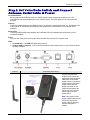
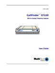
Front Panel LEDs
Once the power is connected, the LEDs on the front panel will present information about the
CallFinder’s wireless modem functions, including signal strength.
CallFinder LED Descriptions
RI
RING INCOMING - Indicates an incoming ring from the wireless module.
CD
CONNECT DATA – This LED is not used as it is for future potential products.
LS
LINK STATUS - This LED blinks when there is network activity between the carrier and the
cellular module.
OH
OFF HOOK indicator - This LED lights whenever the FXO or FXS interface is active.
Signal Signal Strength - Three LEDs. If at least one LED (the left-most LED) is lit, there is enough
signal to maintain the wireless connection with Low signal strength. If the left two LEDs are
lit, a Medium signal strength is present. If all three LEDs are lit, a High signal strength is
present.
Step 3. Using AT Commands to Verify Signal
Strength and Network Registration
3A. Open the Communications Program
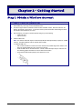
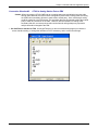
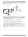
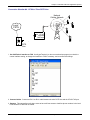
A1. Connect the command cable between the CallFinder and the command computer. The CallFinder
is shipped with a standard DB9 serial cable, male at one end (for attachment to the CallFinder) and
female at the other end (for attachment to the command computer).
NOTE: If your command computer has no serial ports but has only USB ports instead, you
must obtain a USB2.0-to-Serial adapter (“dongle”) for use between the serial cable
and your computer’s USB port. This USB2.0-to-Serial adapter must have a male end
to attach to the DB9 cable.
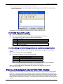
A2. At the command PC, open the HyperTerminal (or equivalent) communications program.
Multi-Tech Systems, Inc.
CallFinder GSM Cellular Gateway
11