1
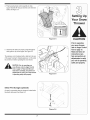
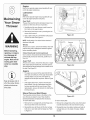
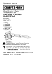
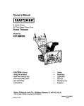
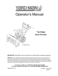
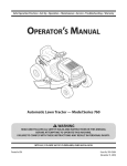
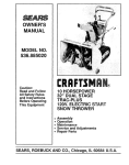
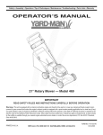
Safety • Set-Up • Operation • Adjustments • Maintenance • Troubleshooting • Parts Lists • Warranty
Two-Stage Snow Thrower
iMPORTANT
READ SAFETY
RULES AND iNSTRUCTiONS
CAREFULLY
BEFORE
OPERATION
Warning: This unit is equippedwithan internalcombustionengineand shouldnot be usedon or nearany unimprovedforest-covered,brushcoveredor grass-coveredland unlesstheengine'sexhaustsystemis equippedwith a sparkarrestermeetingapplicablelocalor statelaws(if any).
If a sparkarresteris used,it shouldbe maintainedin effectiveworkingorder by the operator.In theState of Californiathe aboveis requiredbylaw
(Section4442 of the CaliforniaPublicResourcesCode). Otherstatesmay havesimilarlaws.Federallaws applyon federallands.A sparkarrester
for the muffleris availablethroughyour nearestengineauthorizedservicedealeror contactthe servicedepartment,RO. Box361131Cleveland,
Ohio 44136-0019.
PRINTEDIN U.S.A.
ForUSCustomers:MTDLLC,P.O.BOX361131CLEVELAND,OHIO44136-0019
For CanadianCustomers: MTDProductsLtd.,P.O.BOX 1386,KITCHENER,ONTARION2G4J1
769-03501
09/20/07
This Operator's Manual is an important part of your new snow thrower, it will help you assemble,
prepare and maintain the unit for best performance.
Please read and understand what it says.
Table of Contents
Safety Labels ......................................................
Safe Operation Practices ...................................
Setting UpYour Snow Thrower ..........................
Operating Your Snow Thrower .........................
MakingAdjustments
.........................................
3
4
6
10
14
Maintaining Your Snow Thrower ......................
Off-Season Storage ..........................................
Trouble Shooting ..............................................
Warranty ............................................................
illustrated Parts Lists .......................................
16
19
20
21
22
Finding and Recording Model Number
BEFOREYOU START ASSEMBLING
YOUR NEW EQUIPMENT,
please locate the model plate on the equipment and copy the
the model number and the serial number to the sample model
plate provided to the right. You can locate the model plate by
standing at the operating position and looking down at the
frame.
Model
Number
Num6ro
de mod61e
XXXXXXXXXXX
Serial
Num6ro
Number
de s6rier
XXXXXXXXXXX
MTD LLC
OH 44136
PRODUCTS LIMITED
KITCHENER, ON N2G 4J1
USA-www.mtdproducts.com
CAN-www.mtdcanada.com
1-800-800-7310
1-800-668-1238
Customer Support
Please do NOTreturn
the unit to the retailer from which it was purchased,
without first contacting Customer Support.
If you have difficulty assemblingthis product or have any questions regardingthe controls, operation or maintenance of this unit,
you can seek help from the experts. Choose from the options below:
1. For US Customers: Visit www.yardman.comfor many useful suggestions,click on Customer Support button.
For Canadian Customers: Visit www.yardman.cafor many useful suggestions, click on CustomerSupport button.
2. Call a Customer Support Representative,
For US Customers: 1-330-220-4MTD (4683)or 1-800-800-7310
For Canadian Customers: 1-800-668-1238
3. The engine manufacturer is responsiblefor all engine-related issues with regards to performance, power-rating,specifications, warranty and service. Please refer to the engine manufacturer's Owner's/Operator's Manual, packed separatelywith
your unit, for more information.
Please have your unit's model number and serial number readywhen you call. See previous section to locate this information.
You will be asked to enter the serial number in order to processyour call.
2
222
WARNING
STOP
CS00071
,m#
mmmmmmmmm
A chute clean-out tool isfastened to the top
of the auger housingwith a mounting clip. The
tool isdesigned to clear a chute assembly of
ice and snow.
This item is fastened with a cable tie at the
ChuteClean-out
Tool
factory. Cut the cable tie before operating the
snow thrower.
_
J
hands to clear
a clogged
chute
WARNING:
Never
use your
assembly. Shut off engine and
remain behind handles until
all moving parts have stopped
before using the clean-out tool
to clear the chute assembly.
3
This symbol points
out importantsafety
instructionswhich,
if not followed, could
endanger the personal safety and/or
propertyof yourself
and others. Read and
follow all instructions
in this manual before
_ttempting to operate
this machine. Failure
to comply with these
instructionsmay
result in personal
injury.When you see
this symbol, HEED
iTS WARNING!
four Responsibility
::restrictthe use
of this power machine
to persons who read,
understand
and follow the warnings
and instructions
in this manual
and on the machine.
WARNING: Engine Exhaust, some of its constituents, and certain vehicle components contain or emit chemicals known to State of Californiato cause cancer and
birth defects or other reproductiveharm.
DANGER: This machine was built to be operated according to the safe operation practices in this
manual. As with any type of power equipment, carelessness or error on the part of the operator can
result in serious injury. This machine is capable of amputating hands and feet and throwing objects.
Failureto observe the following safety instructions could result in serious injury or death.
Training
WARNING
This symbolpoints
out importantsafety
instructionswhich,
if not followed, could
endangerthe personal safetyand/or
property of yourself
and others. Read and
follow all instructions
inthismanualbefore
attemptingto operate
thismachine.Failure
i to complywith these
instructions
may
; resultin personal
injury.When you see
this symbol, HEED
iTS WARNING!
Your Responsibility
Restrict the use
of this power machine
to persons who read,
understand
I and follow the warnings
and instructions
in this manual
and on the machine.
Safe Handling
1. Read,understand,andfollowall instructionson the
machineandin the manual(s)beforeattemptingto
assembleand operate.Keepthis manualina safe placefor
futureandregularreferenceandfor orderingreplacement
parts.
2. Be familiarwithall controlsandtheir properoperation.
Knowhowto stopthe machineanddisengagethem quickly.
3. Neverallowchildrenunder14 yearsoldto operatethis
machine.Children14 yearsold andovershouldread and
understandthe instructionsandsafe operationpractices
inthis manualand on the machineand be trainedand
supervisedbyan adult.
4. Neverallowadultsto operatethis machinewithoutproper
instruction.
5. Thrownobjectscan causeserious personalinjury.Plan
yoursnow-throwingpatternto avoiddischargeof material
towardroads,bystandersandthe like.
6. Keepbystanders,helpers,pets andchildrenat least 75 feet
fromthe machinewhileit is in operation.Stopmachineif
anyoneentersthe area.
7. Exercisecautionto avoidslippingor falling,especially
when operatingin reverse.
of Gasoline
Toavoid personalinjury or propertydamage use extremecare
in handlinggasoline.Gasolineis extremelyflammableandthe
vaporsare explosive.Serious personalinjury can occur when
gasolineis spilled on yourselfor your clothes,whichcan ignite.
Washyourskin andchangeclothesimmediately.
a. Useonly an approvedgasolinecontainer.
b. Extinguishall cigarettes,cigars, pipes andothersources
of ignition.
c. Neverfuel machineindoors.
d. Neverremovegas cap or add fuel whilethe engineis hot
or running.
e. Allow engineto coolat leasttwo minutesbeforerefueling.
f. Neveroverfill fuel tank. Filltank to no morethan Y2inch
below bottomoffiller neckto providespacefor fuel
expansion.
g. Replacegasolinecap andtighten securely.
h. If gasolineis spilled,wipe it off the engine and equipment. Movemachineto another area.Wait 5 minutes
beforestartingthe engine.
i. Neverstorethe machineor fuel containerinside where
there is an openflame, sparkor pilot light (e.g.furnace,
waterheater,spaceheater,clothesdryeretc.).
j. Allow machineto cool at least5 minutesbeforestoring.
Preparation
1. Thoroughlyinspectthe area wherethe equipmentis to be
used. Removeall doormats,newspapers,sleds, boards,
wiresand otherforeignobjects,whichcould be tripped
overor thrown bythe auger/impeller.
2. Alwayswearsafetyglasses or eye shieldsduring
operationand whileperformingan adjustmentor repair
to protectyour eyes.Thrownobjectswhich ricochetcan
causeseriousinjury to the eyes.
3. Do not operatewithoutwearingadequatewinteroutergarments. Donot wearjewelry, long scarvesor otherloose
clothing,whichcould becomeentangledin movingparts.
Wearfootwearwhichwill improvefooting on slippery
surfaces.
4. Usea groundedthree-wireextensioncordand receptacle
forall units withelectric startengines.
5. Adjustcollectorhousingheight to cleargravel or crushed
rock surfaces.
6. Disengageall control leversbeforestartingthe engine.
7. Neverattemptto makeany adjustmentswhileengineis
running,exceptwherespecificallyrecommendedinthe
operator'smanual.
8. Let engine andmachineadjustto outdoortemperature
beforestartingto clearsnow.
4
Operation
Maintenance
1. Donot put hands or feet near rotatingparts, inthe
auger/impellerhousingor chuteassembly.Contactwiththe
rotatingparts can amputatehands andfeet.
2. The auger/impellercontrolleveris a safetydevice.Never
bypassits operation.Doingso makesthe machineunsafe
and may causepersonalinjury.
3. The controlleversmustoperate easilyin bothdirections
and automaticallyreturnto the disengagedpositionwhen
released.
& Storage
1. Nevertamper withsafetydevices.Checktheir proper
operationregularly.Referto the maintenanceandadjustmentsectionsof this manual.
2. Beforecleaning,repairing,or inspectingmachinedisengage
all control leversandstop the engine.Wait untilthe
auger/impellercometo a completestop.Disconnectthe
sparkplug wireand groundagainstthe engineto prevent
unintendedstarting.
3. Checkbolts and screwsfor propertightness at frequent
intervalsto keepthe machinein safe workingcondition.
Also,visuallyinspectmachinefor any damage.
4. Do not changethe engine governorsettingor over-speed
the engine.The governorcontrols the maximumsafe
operatingspeed of the engine.
5. Snowthrowershaveplatesand skidshoesare subjectto
wearanddamage. For yoursafetyprotection,frequently
check all componentsand replacewith originalequipment
manufacturer's(OEM) parts only."Use of partswhich do
not meetthe original equipmentspecificationsmaylead to
improperperformanceandcompromisesafety!"
6. Checkcontrols periodicallyto verify they engageand
disengageproperlyandadjust, if necessary.Referto the
adjustmentsection inthis operator'smanualfor instructions.
7. Maintainor replacesafetyandinstructionlabels, as necessary.
8. Observeproper disposallaws andregulationsfor gas, oil,
etc. to protectthe environment.
9. Priorto storing,run machinea few minutesto clearsnow
from machineand preventfreezeup of auger/impeller.
10. Neverstorethe machineor fuel containerinside where
thereis an openflame, sparkor pilot lightsuch as a water
heater,furnace, clothesdryeretc.
11. Alwaysreferto the operator'smanualfor proper instructions
on off-seasonstorage.
4. Neveroperate witha missingor damagedchuteassembly.
Keepall safetydevicesin place andworking.
5. Neverrunan engineindoorsor in a poorlyventilatedarea.
Engineexhaustcontainscarbonmonoxide,an odorlessand
deadly gas.
6. Donot operate machinewhile underthe influenceof alcohol
or drugs.
7. Mufflerandengine becomehot andcan causea burn.Do
not touch.
8. Exerciseextremecaution when operatingon or crossing
gravel surfaces.Stay alert for hidden hazardsor traffic.
9. Exercisecaution when changingdirectionandwhileoperating on slopes.
10. Plan yoursnow-throwingpatternto avoid dischargetowards
windows,walls, cars etc. Thus, avoidingpossibleproperty
damage or personalinjury causedby a ricochet.
11. Neverdirect dischargeat children,bystandersand pets or
allow anyonein front of the machine.
12. Donot overloadmachinecapacity byattemptingto clear
snow at too fast of a rate.
13. Neveroperatethis machinewithoutgoodvisibility or light.
Alwaysbe sure of yourfooting and keepa firm hold on the
handles.Walk, neverrun.
14. Disengagepowerto the auger/impellerwhentransportingor
not in use.
15. Neveroperate machineat hightransport speedson slippery
surfaces. Lookdownand behindand use care when
Do not modify
engine
Toavoid seriousinjury or death,do not modifyengine inany
way.Tamperingwiththe governorsettingcan leadto a runaway
engineandcauseit to operateat unsafespeeds.Nevertamper
withfactorysettingof enginegovernor.
backingup.
16. Ifthe machineshouldstartto vibrate abnormally,stop the
engine,disconnectthe sparkplug wire and groundit against
the engine.Inspectthoroughlyfor damage.Repairany
damage beforestartingandoperating.
17. Disengageall control leversandstop engine beforeyou
leavethe operatingposition (behindthe handles).Wait
untilthe auger/impellercomesto a completestop before
uncloggingthe chuteassembly,makingany adjustments,or
inspections.
18. Neverput yourhand in the dischargeor collectoropenings.
Alwaysuse the clean-outtool providedto unclogthe discharge opening.Donot unclogchuteassemblywhileengine
is running.Shut off engine and remainbehindhandlesuntil
all movingparts havestoppedbefore unclogging.
19. Useonly attachmentsandaccessoriesapprovedbythe
manufacturer(e.g. wheelweights,tire chains,cabs etc.).
20. If situationsoccurwhich are not coveredin this manual,use
care and goodjudgment. Call customerassistancefor the
nameof yournearestservicingdealer.
Notice
regarding
Emissions
Engineswhichare certifiedto complywithCaliforniaandfederal
EPAemissionregulationsfor SORE(SmallOff RoadEquipment)
arecertified to operateon regularunleadedgasoline,and may
includethe followingemissioncontrolsystems:EngineModification (EM)andThreeWayCatalyst(TWO)if so equipped.
Average
Useful
Life
Accordingto the ConsumerProductsSafetyCommission
(CPSC)andthe U.S.EnvironmentalProtectionAgency(EPA),
thisproducthas an Average UsefulLife of seven(7) years,or
60 hoursof operation.At the end of the Average UsefulLife,
buya newmachineor havethe machineinspectedannuallyby
an authorizedservicedealerto ensurethat all mechanicaland
safetysystemsare workingproperlyandnot wornexcessively.
Failureto do so can resultin accidents,injuriesor death.
5
WARNING
This symbol points
out important safety
instructions,which
if not followed, could
endanger the personal safety and/or
property of yourself
and others. Read and
follow all instructions
in this rnanuai before
attempting to operate
this machine. Failure
to complywith these
instructions may
result in personal
injury.When you see
this symbol, HEED
IT'S WARNING!
Your Responsibility
Restrict the use
of this power machine
to persons who read,
understand
and follow the warnings
and instructions
in this manual
and on the machine.
IMPORTANT:The snowthroweris shippedwith oil
and WITHOUTGASOLINE.After assembly,referto
separateenginemanualfor properfueland engineoil
recommendations.
1. Observethe lowerarea of the snowthrowerto be sure
bothcables are alignedwith rollerguides.
a. Pull up and backon upperhandleas shownin
Figure3-1.Align upper handlewith the lower
handle.
b. Tightenhandknobs securingupperhandleto
lowerhandle.
2. Removewingnutand hexscrewfrom chutecontrol
assemblyand clevispin and cotter pin fromchute
supportbracket.See Figure3-2. Positionthe chute
assembly(forward-facing)overthechute base.
NOTE:References
to
rightorleftsideofthe
snowthroweraredeterminedfrombehindthe
unitintheoperating
position.
NOTE:ThisOperator's
Manualcoversseveral
models,handlepanels,
lightsandchutecranks
aresomefeatures
that
mayvarybymodel.
Notallfeaturesreferencedinthismanual
areapplicable
toall
snowthrowermodels.
3. Placechuteassemblyonto chutebaseand secure
chutecontrolassemblyto chutesupport bracketwith
clevispin and cotterpin removedearlier.See Figure
3-3.
Figure 3-1
Figure 3=2
NOTE:Tworeplacementaugershearpins
areincludedwiththis
manual(orstowed
i intheplastichandle
panel).RefertoAugers
,i intheMaintainance
Sectionformore
information
regarding
shearpinreplacement.
Figure 3=3
6
4. Finishsecuringchute controlassemblyto chute
support bracketwith wingnut and hexscrew removed
earlier.See Figure3-4.
Setting U p
CAUTION
Figure 3=4
Prior to operating
your snow thrower,
refer to Auger Control
5. Checkthat all cablesare properlyroutedthroughthe
cable guideon topof the engine.See Figure3-5.
Test on page 13.
Read and follow all
instructions care-
The extensioncord is fastenedwith a cabletie to the rear
of the auger housingfor shippingpurposes.Cut thecable
tie and removeit beforeoperatingthe snowthrower.
fully and perform all
adjustments to verify
your unit is operating
safely and properly.
CAUTION:Priorto operating your
snowthrower, referto Auger Control
Teston page 13. Readand follow all
instructionscarefully,and performall
adjustments to verify your snowthrower
is operating safely and properly.
Figure 3=5
/
Shear
Pin Storage
(optional)
An areafor convenientshearpin storageis locatedunder
the plasticdashpanel.See Figure3-6.
/Y
,%
Figure 3=6
7
Drift Cutters
(If Equipped)
Driftcutters shouldbe usedwhenoperatingthe snow
throwerin heavy drift conditions.
On modelsso equipped,drift cuttersand hardware
are assembledto the auger housinginverted.See
Figure3-7.
• Removethecarriageboltsand wingnutssecuringthe
drift cuttersto the housing.
• Repositiondrift cuttersso they face forwardas shown
in Figure3-8. Securewith hardwarepreviously
removed,wingnutsshouldbe fastenedon the outside
of the housingas shown.
If yourunit is not equippedwith drift cutters,you may
contactCustomerSupportas instructedon page 2 for
informationregardingpriceand availability.
Figure 3=7
SnowthrowerModel Drift CutterKit:
All models
0EM-390-679
WARNING
Neveruseyour hands
to cleansnowand
icefromthe chute
assemblyorauger
housing.
iMPORTANT
Figure 3=8
Underany circumstance do not exceed
manufacturer's recommended psi. Equaltire
pressure should be
maintained at all times.
i Excessivepressure
when seating beads
may cause tire/rim
assembly to burst
with force sufficient to
cause serious injury
Referto sidewall of
tire for recommended
pressure.
8
Clean-Out
Tool
Theclean-outtool is mountedto the rear of the auger
housingand is designedto cleara cloggedchute.Refer
to page 11for instructionson howto properlyuseit.
Clean=Out
Tool
NOTE: This itemisfastenedwith a cabletie to the rear
of the augerhousingat the factory.Cutthe cabletie
beforeoperatingthe snowthrower.
_
clean snowand ice from the chute
ARNING:Never use your handsto
assembly or auger housing.
ThrOWer
_jJ_
Figure 3-9
Lamp Wiring
Harness
(If equipped)
The poston the cabletie attachingthe lampwiring
harnessto the lowerhandleshouldbe pluggedintothe
hole in the lowerhandle. Pull the slackportionof the
wiringharnessthroughthe cabletie to preventinterferencewith the recoilstarterhandle.
WARNING
Never use your hands
to clean snow and
ice from the chute
assembly or auger
housing,
Figure 3-10
Skid Shoes
General
Positionthe skid shoesbasedon surfaceconditions.
1. Alwaysobservesafetyruleswhenperforming
anymaintenance.
Adjust upwardfor hard-packedsnow.Adjustdownward
whenoperatingon gravelor crushedrock surfaces.See
"MakingAdjustment"Section.
Tire Pressure
(Pneumatic
Recommendations
2. Thewarrantyon this snowthrowerdoes notcover
itemsthat havebeensubjectedto operatorabuse
or negligence.To receivefull valuefrom warranty,
operatormustmaintainthe snowthroweras
instructedhere.
Tires)
3. Someadjustmentswillhaveto be madeperiodically
The tires are over-inflatedfor shippingpurposes.Check
to maintainyour unitproperly.
the tire pressurebeforeoperatingthe snowthrower.Refer
to the tire sidewall for tire manufacturer'srecommended 4. Periodicallycheckall fastenersand makesurethese
are tight.
psi and deflate(or inflate)thetires as necessary.
NOTE: Ifthe tire pressureis not equal in bothtires, the
unit may nottravel in a straightpathand the shaveplate
may wearunevenly.
i
_
i
i
Excessive pressure
when seating beads
may cause tireirim
assembly toburSt
with force sufficient to
cause seriousinjuryl
Refer to sidewall of
tire for rec0mmended
pressure:
9
i
iMPORTANT
Under any circum:
stance do not exceed
manufactureCs recom_
mended psL EqUaltire
pressure should be
maintained at all times:
Drive Control
.Shift Lever
Four-Way
Chute ControlTM
Heated Handles
Switch (en option)l-
uger Control
Headlight _
Wheel Steering
Control 1
Electric Start
ThrOWer
Gas Ca
Oil
Engine Controls
RecoilStarter
Handle
Electric
StarterOutlet
Ignition
Key
WARNING
X
Read,understand,
and follow all instructions and warnings
onthe machineand
in this manual before
operating.
Choke
Control
]ool
1 If Equipped
Throttle
Control
Shoe
•
J
Figure 4-1
Use extreme care
hen handling
gasoline. Gasoline is
extremely flammable
and the vapors are
explosive. Neverfuel
the machine indoors
or while the engine
is hot or running.
Extinguish cigarettes,
cigars, pipes and
other sources of
ignition.
Now that youhaveset up yoursnowthrowerfor operation, getacquaintedwith its controlsand features.These
are describedbelowand illustrated in Figure4-1.This
knowledgewillallow youto use yournewequipmentto
its fullest potential.
NOTE: Fordetailedstartinginstructionsand more
informationon all enginecontrols,referto the separate
enginemanualpackedwith your unit.
Shift
Lever
6
The shiftleveris locatedon the rightside
of the handlepanel.Placethe shift lever
4,
Forward
Yoursnowthrowerhas six forward(F)
3
speeds,with positionnumberone (1)
beingthe slowestspeed.
Reverse
t 2
Control
III
Thechokecontrol is foundon the rear of the engineand
is activatedby rotatingthe knobclockwise.Activatingthe
chokecontrolclosesthe chokeplateon thecarburetor
and aids in startingthe engine.
Throttle
intoany of eightpositionsto controlthe
directionof traveland groundspeed.
Yoursnowthrowerhastwo reverse(R)
speeds,with positionnumberone (1)
beingthe slowerspeed.
Choke
Control
Thethrottlecontrolis locatedon the engine.
it regulatesthe speedof theengineand
will shutoff the enginewhenpusheddown
completely.
Primer
1
Depressingthe primerforcesfuel directly
intothe engine'scarburetorto aid in coldweatherstarting.
Oil Fill
R1
Engineoil levelcan be checkedand oil
addedthroughthe oil fill.
R2
10
* Tochangethe directioninwhich snowis thrown,
squeezethe buttonon thejoy-stickand pivot the
joy-stick
to the rightor to the left.
Auger Control
f
* Tochangethe angle/distancewhich snow isthrown,
pivotthejoy-stickforwardor backward.
Wheel
Steering
Controls
The left and rightwheelsteeringcontrolsare locatedon
the undersideof the handles.Squeezethe rightcontrolto
turn right; squeezethe left control to turnleft.
NOTE:Operatethe snowthrowerin openareas untilyou
are familiarwith these controls.
Theauger controlis locatedon the left handle.Squeeze
thecontrol grip againstthe handleto engagethe augers
and start snowthrowingaction. Releaseto stop.
Drive Control/Auger
f
Control
Lock
DRIVE
CONTROL
Ignition
Clean-Out
Tool
1. Releaseboththe augercontroland thedrive/auger
control lock.
2. Stopthe engine by movingthe throttleto the stop
position.
Four-Way
Chute Control
4. Usethe shovel-shapedend of the clean-outtoolto
removeanysnow and ice in the chute assembly.
5. Re-fastenthe clean-outtoolto themountingclip on
the rear of the augerhousingand restartengine.
6. Whilestandingin theoperator'sposition(behindthe
snowthrower),engagethe augercontrol fora few
secondsto clearany remainingsnowor ice from the
chute assemblybeforecontinuingto clearsnow.
Switch
(if Equipped)
This switchis locatedon the rightside of the snow
throwerdashpanel.Toactivatethe heatedhandles,
togglethe switchto the rightto generateheatwithinthe
handlegrips. Togglethe switchto the left to the OFF
positionafter usingthe snowthrower.
TM
CHUTE DiRECTiONAL CONTROL
CHUTETILT DOWN
NOTE:The heatedhandlesgrips are a complimentto,
nota substitutefor, propercold weatherouterwearfor
the operator'shands.It is recommendedthat the snow
throweroperatorweargloves/mittensto avoidextremities
of winterwhile operatingthis equipment.
jPUSH BUTTOHi
CHUTEROTATE
RIGHT
CHUTETiLT UP
3. Removethe clean-outtool from the mountingclip.
Heated Handles
f
Th rowe r
Key
WARNING:Never use your hands to
clear a clogged chute assembly. Shut
off engine and remain behind handles
until ail moving partshave stopped
before unclogging.
iMPORTANT:Alwaysreleasethe drivecontrolbefore
changingspeeds.
Snow
The ignitionkeymustbe insertedand snappedin place
inorder forthe engineto start. Removethe ignitionkeyto
preventunauthorizeduseof equipment.Do NOTattempt
to turn the key.
-X
Thedrivecontrol is locatedon the right handle.Squeeze
thecontrol grip againstthe handleto engagethe wheel
drive. Releaseto stop.
Thedrivecontrol alsolocksthe augercontrol soyou can
operatethe chutedirectionalcontrolwithoutinterrupting
the snowthrowingprocess.If the augercontrol isengagedsimultaneouslywith the drivecontrol,the operator
can releasethe augercontrol(on the left handle)and
theaugerswill remainengaged.Releasebothcontrolsto
stop theaugersand wheeldrive.
Operating
j
Thechute directionalcontrolis locatedon the left side of
thedash panel.
11
WARNING
The operation of
any snow thrower
can result in foreign
objects being thrown
intothe eyes, which
can damage your
eyes severely. Always
wear safety glasses
while operating the
snow thrower, or while
performing any adjustments or repairs on it.
Be sure no one other
than the operator is
standing near the sno_
thrower while starting
engine or operating
snow thrower. Never
run engine indoors or
in enclosed, poorly
ventilated areas. Engine exhaust contains
carbon monoxide, an
odorless and deadly
gas. Keep hands, feet,
hair and loose clothing
away from any moving
parts on engine and
snow thrower.
Gas & Oil Fill-Up
Servicethe enginewith gasolineand oil as instructed
in
the separateenginemanualpackedwith your unit. Read
instructionscarefully.
WARNING
7. Whendisconnectingtheextensioncord, always
unplugtheend at thethree-prongwalloutlet before
unpluggingthe oppositeend from the snowthrower.
Recoil Starter
Starting The Engine
1. Attachsparkplug wireto sparkplug. Makecertain the
metalloop on the end of the sparkplug wire (inside
the rubberboot)is fastenedsecurelyoverthe metal
tip on the spark plug.
1. Rotatechokecontrolto FULLchokeposition(cold
enginestart).
2. Makecertain boththe augercontroland drivecontrol
are in thedisengaged(released)position.
2. Pushthe primertwo or threetimesfor coldengine
start, makingsureto covervent hole in the centerof
theprimerwhenpushing.
3. Movethrottlecontrolup to FASTposition.Insert
ignitionkeyinto slot. Makesureit snaps intoplace.
Do notattemptto turn the key.
NOTE:If the engineis alreadywarm,placechokecontrol
in the OFF positioninsteadof FULL.
NOTE:DO NOTuse primerto restarta warm engine
aftera short shutdown.
Read, understand,
and follow all instruc-
NOTE:The enginecannotstart unlessthe key is
insertedintoignitionswitch.
NOTE:Additionalprimingmay be necessaryifthe
temperatureis below150Fahrenheit.
tions and warnings
on the machine and
in this manual before
Electric Starter
1. Determinethat yourhome'swiringis a three-wire
groundedsystem.Ask a licensedelectricianif you are
notcertain.
3. Graspthe recoilstarterhandleand slowlypull the
ropeout. At the pointwhereit becomesslightlyharder
to pull the rope,slowlyallowthe ropeto recoil.
operating.
WARNING:The optional electricstarter
Use extreme care
when handling
gasoline. Gasoline is
extremely flammable
and the vapors are
explosive. Neverfuel
the machine indoors
or while the engine
is hot or running.
Extinguish cigarettes, cigars, pipes
and other sources of
ignition.
If your home's wiring
system is not a
three-wire grounded
system, do not use
this electric starter
under any conditions.
powercord
is
equippedwith
and plug,and
a grounded
is designed
three-wire
to operate on 120volt AC household
current.It must be used with a properly
grounded three-prong receptacle at all
times to avoid the possibilityof electric
shock.Followall instructionscarefully
priorto operating the electric starter,
if youhavea groundedthree-prongreceptacle,proceed
as follows:
1. Plug theextensioncord intothe outletlocatedon the
engine'ssurface.Plugthe otherend of extensioncord
intoa three-prong120-volt,grounded,ACoutlet in a
well-ventilatedarea.
2. Rotatechokecontrol to FULLchoke position(for a
coldengine start).
NOTE: If the engineis alreadywarm,placechokecontrol
inthe OFFpositioninsteadof FULL.
3. Pushthe primertwo or threetimesfor coldengine
start, makingsureto covervent hole in thecenterof
the primerwhenpushing.
4. Pushstarterbuttonto start engine.
electrical system
is grounded,
but a three-hole
5. Oncethe enginestarts,immediatelyreleasestarter
button.
receptacleis not
available, do not use
your snow throweCs
.
Asthe enginewarms,slowlyrotatethe chokecontrol
to the OFFposition.If the enginefalters,quicklyrotate
thechokecontrol backto the FULLpositionand then
slowlyintothe OFF positionagain.
NOTE:Allowthe engineto warmup fora few minutes
after starting.The enginewill notdevelopfull poweruntil
it reachesoperatingtemperatures.
Stopping
The Engine
Runenginefor a few minutesbeforestoppingto help dry
off any moistureon the engine.
Tohelp preventpossiblestarterfreeze-up,proceedas
follows:
Electric
Starter (if Equipped)
1. Connectextensioncord to the electricstarteroutlet
on the engine,then to 120volt AC outlet.
2. Withthe engine running,pushthe starterbutton and
allowthe starterfor spin for severalseconds.The
noisemadebythe starteris normal.The engine's
starteris not beingharmed.
NOTE: DONOT useprimerto restarta warm engine
after a short shutdown.
If your home
4. Pullthe starterhandlewith a firm, rapidstroke. Donot
releasethe handleand allowitto snapback.Keepa
firm holdon the starterhandleand allowitto slowly
recoil.
3. Whendisconnectingtheextensioncord, always
unplugtheend at thethree-prongwalloutlet before
unpluggingthe oppositeend from the snowthrower.
4. Movethrottlecontrol to STOPposition.
6. As theengine warms,slowlyrotatethe chokecontrol
to the OFF position.If the enginefalters,quickly
rotatethe chokecontrol backto FULLand thenslowly
intothe OFF positionagain.
electricstarter.
12
5. Removethe ignitionkey (Do notturn key)to prevent
unauthorizeduseof equipment.
6. Wipeall snow and moisturefromthe area aroundthe
engineaswell as the area inand aroundthe drive
controland augercontrol.Also, engageand release
bothcontrolsseveraltimes.
2. Ina well-ventilatedarea,startthe snowthrower
engineas instructedon the previouspage.Make sure
the throttleis set in the FASTposition.
NOTE: Keepthe keyin a safe place.Theengine cannot
startwithoutthe ignitionkey.
Recoil Starter
3. Whilestandingin theoperator'sposition(behindthe
snowthrower),engagethe auger.
1. With enginerunning,pull starter ropewith a rapid,
continuousfull arm strokethreeor fourtimes. Pulling
the starterropewill producea loud clatteringsound,
which is notharmfulto engine.
4. Allowthe augerto remainengagedfor approximately
ten (10) secondsbeforereleasingthe augercontrol.
Repeatthis severaltimes.
2. Movethrottlecontrolto STOPposition.
5. With the throttlecontrolin the FAST(rabbit)position
and the augercontrol in the disengaged"up"position,
walk to the front of the machine.
3. Removethe ignitionkey (Do notturn key) to prevent
unauthorizeduseof equipment.
NOTE: Keepthe keyin a safe place.Theengine cannot
startwithoutthe ignitionkey.
4. Wipeall snowand moisturefrom thearea aroundthe
engineas wellas the area in and aroundthe drive
controland augercontrol.Also,engageand release
bothcontrolsseveraltimes.
6. Confirmthat the auger hascompletelystopped
rotatingand showsNOsigns of motion.If the auger
showsANYsigns of rotating,immediatelyreturnto
the operator'spositionand shut off the engine.Wait
for ALL movingparts to stop beforere-adjustingthe
auger control.
To Engage Drive
7. To readjustthe controlcable, loosenthe upper hex
nuton the augercable bracket.
With theengine runningneartop speed,move
shift leverto oneof six FORWARDpositionsor two
REVERSEpositions.Selecta speedappropriatefor
the snowconditionsthat exist.
8. Positionthe bracketupwardto providemoreslack(or
downwardto increasecabletension).See Figure4-2.
9. Retightenthe upperhex nut.
10.RepeatAuger ControlTestto verifyproperadjustment
hasbeen achieved.
2. Squeezedrivecontrol againstthe righthandleand
the snowthrowerwill move.Releaseit and the drive
motionwill stop.
WARNING
Never use your hands
toclean
snowand
ice from the chute
assembly or auger
The muffler, engine
and surrounding
areas become hot
and can cause a
burn, Do not touch,
3. Toturnthe unitleft or right, squeezethe respective
wheelsteeringcontrol.See Figure4-1.
To Engage Augers
1. Toengageaugersand startsnow throwing,squeeze
the left hand augercontrolagainstthe left handle.
Releaseto stopaugers.
When selecting a
Drive Speed, use the
slower speeds until
!ou are comfortable
and familiar with the
2. Whiletheauger controlis engaged,squeezethe drive
controlto move,releaseto stop. Donot shiftspeeds
whilethe driveis engaged.
NOTE:This sameleveralso locksauger controlso you
canturn the chutecontrolwithoutinterruptingthe snow
throwingprocess.
operation of the snow
thrower.
Figure 4=2
3. Releasethe augercontrol;the interlockmechanism
shouldkeeptheauger controlengageduntil the drive
controlis released.
.
NEVER reposition the
shift lever (change
speeds or direction
of travel) without first
releasing the drive
control and bringing
the snow thrower
Releasethe drivecontrolto stop boththe augersand
thewheeldrive. Tostop theauger,bothleversmust
be released.
Auger Control Test
Performthe followingtestbeforeoperatingyour snow
throwerfor the first time and at the startof eachwinter.
to a complete stop.
Doing so will result in
_remature wear to the
snow thrower's drive
Checkthe adjustmentof the augercontrol asfollows:
1. Whentheauger controlis releasedand in the
disengaged"up"position,the cable shouldhavevery
little slack. It shouldNOTbe tight.
system.
13
Shift Cable
If the full rangeof speeds(forwardand reverse)cannot
be achieved,referto the figureto the left and adjustthe
shiftcable as follows:
1. Placethe shiftleverin the fastest forwardspeed
position.
2. Loosenthe hex nuton the shiftcableindexbracket.
See Figure5-1.
3. Pivotthe bracketdownwardto take up slack in the
cable.
4. Retightenthe hex nut.
5. Checkforcorrectadjustmentbeforeoperatingthe
snowthrower.
Chute
Figure 5=1
Control
Oncea seasonor every 25 hoursof operation,whichever
isearlier,checkwhetherthe four-waychutecontroFM
cableshaveslackened,if the chute doesnot rotate
fully or itspitch cannotbe movedup or down,the chute
controlcableswill haveto be adjusted.
Toadjustthese cables,proceedas follows:
WARNING
Read, understand,
and follow all instruc-
1. Totightencable, loosenthe top nutand tightenthe
bottomnuton thecable.
tions and warnings
on the machine and
in this manual before
2. Adjustequallyon both sidesby workingon both
cables.See Figure5-2.
operating.
Drive Control
i Never attempt to
make any adjust-
& Shift
Lever
Whenthedrivecontrol is releasedand in thedisengaged
"up"position,the cableshouldhavevery little slack. It
shouldNOTbe tight.
Checktheadjustmentof the drivecontrolas follows:
1. With the drivecontrol released,pushthe snowthrower
gentlyforward.The unit shouldroll freely.
i merits while the
engine is running,
i except where specified in operator's
' manual.
2. Engagethe drivecontrol and gentlyattemptto push
the snowthrowerforward.Thewheelsshouldnot turn.
Figure 5=2
Theunit shouldnot roll freely.
3. With the drivecontrol released,movethe shift lever
back and forth betweenthe R2 positionand the F6
positionseveraltimes. Thereshouldbe no resistance
in theshift lever.
4. If anyof the abovetests failed, thedrivecable is in
need of adjustment.Proceedas follows:
5. Loosenthe lowerhex nuton the drivecable bracket.
See Figure5-3.
6. Positionthe bracketupwardto providemoreslack(or
downwardto increasecabletension).
7. Retightenthe lowerhex nut.
J
Figure 5=3
Youcan alsocheckthe adjustmentas follows:
1. With the snowthrowertipped forward(be certainto
drain gasolineor place plasticfilm underthe gascap if
the snowthrowerhasalreadybeenoperated),remove
the framecoverunderneaththe snow throwerby
removingthe self-tappingscrews. See Figure6-5 on
page 17.
14
2. With the drivecontrol released,there mustbe 1/8"
clearancebetweenthe frictionwheeland the drive
pulleyin all positionsof theshift lever.
3. With the drivecontrolengaged,the frictionwheelmust
contactthe drive pulley.See Figure6-8.
4. If adjustmentis necessary,loosenthe lowerhexnut
on the drivecableindexbracketand pivot the bracket
upwardor downwardas necessary.Referto Figure
5-3. Tightenthe lowerhexnut to securethe bracket
whencorrectadjustmentis reached.
Mak i ng
AdjuStments
5. Reassemblethe frame coverand returnthe unitback
to its operatingposition.
NOTE: if you placedplasticunderthe gas cap, be certain
to removeit now.
Skid Shoes
The spacebetweenthis shaveplateand the groundcan
be adjusted.Forclose snow removal,placeskid shoes in
the lowposition.Use middleor high positionwhenarea to
be clearedis uneven.
Figure 5-4 - Standard
Skid Shoe
IMPORTANT
It is not recommended
that you operate this
snowthrower on gravel
as loose gravelcan be
easily picked up and
thrown by the auger
causing personal injury
or damageto the snow
thrower,
If for some reason.
1. Adjust skid shoesby looseningthefour locknuts
and carriageboltsand movingskid shoesto desired
position.See Figure5-4 or 5-5.
2. Makecertainthe entirebottomsurfaceof skid shoes
are againstthe groundto avoidunevenwearon the
skid shoes.
3. Tightennuts and bolts securely.
NOTE: Somemodelsare equippedwith heavyduty skid
shoes and may be turnedoverto increasetheir lifespan.
See Figure5-5. If shoesare turnedthey mustalso
changesidesto ensurethe "A"on the shoeis towardsthe
front of the unit.
you have to operate
the snow thrower on
Figure 5-5 - Reversible Skid Shoe
Auger Control
Toadjust the augercontrol,referto page 13.
gravel,keep the skid
shoe in the highest
position for maximum
clearance between the
groundand the shave
plate.
15
=,
Engine
Referto the separateengine manualpackedwith your
unitfor all enginemaintenance.
Lubrication
Maintainin,
Engine
Referto the separateengine manualpackedwith your
unitfor all enginelubricationinstructions.
Gear Shaft
Thegear (hex) shaftshouldbe lubricatedat least once
a seasonor after every25 hoursof operation.
1. Carefullypivotthe snowthrowerup and forwardso
that it restson the augerhousing.
2. Removethelowerframe coverby removingthe two
screwswhichsecureit.
Figure 6-1
3. Applya lightcoatingof an all-weathermulti-purpose
oil to thehex shaft. See Figure6-1.
NOTE:Avoidgettingoil on rubberfrictionwheeland
aluminumdriveplate.
Wheels
At leastonce a season,removeboth wheels.Cleanand
coat theaxles with a multipurposeautomotivegrease
beforereinstallingwheels.
Chute Directional Control (optional)
Oncea season,thejoystickshouldbe lubricatedwith
petroleumjelly,linseedoil, mineraloil, paraffinwax or
3-in-1oil.
Auger Shaft
At leastonce a season,removethe shearpinson auger
shaft. Spraylubricantinsideshaft, aroundthe spacers.
Alsolubricatethe flangebearingsfoundat eitherend of
the shaft. See Figure6-2.
Keep all grease and oil
Offof the rubber friction
wheel and aluminum
drive
,
Figure 6=2
Augers
• Theaugersare securedto the spiralshaftwith two
shearpinsand cotterpins. If the augershouldstrike
a foreignobject or icejam, the snowthroweris
designedso that the pinsmay shear.Referto Figure
6-2.
If the augerswill notturn, checkto seeif the pins
havesheared.One set of replacementshearpins
hasbeen providedwith the snowthrower.When
replacingpins, sprayan oil lubricantintoshaft before
insertingnewpins.
i
Shave
Plate and Skid Shoes
Theshaveplateand skid shoeson the bottomof the
snowthrowerare subjectto wear.Theyshouldbe
checkedperiodicallyand replacedwhennecessary.
Toremoveskid shoes:
.
J
Figure 6=3
Toremoveshaveplate:
Removethefour carriagebolts and hexflangenuts
which securethem to the snowthrower.
2. Reassemblenew skid shoeswith the fourcarriage
bolts (two on each side)and hexflange nuts.Refer
to Figure6-3.
1. Removethecarriageboltsand hexnuts whichattach
itand the skid shoesto the snowthrowerhousing.
2. Reassemblenew shaveplate,makingsureheadsof
carriagebolts are to the insideof housing.Tighten
securely.
16
Auger
Belt Replacement
To removeand replaceyour snowthrower'sauger belt,
proceedasfollows:
1. Removethe plasticbeltcover on the front of the
engine by removingthe two self-tappingscrews. See
Figure6-4.
NOTE: Drainthe gasolinefrom the snowthrower,or
placea pieceof plasticunderthe gas cap.
.
.
/
Carefullypivotthe snowthrowerup and forwardso
that it restson the augerhousing.Removethe frame
coverfrom the undersideof the snow throwerby
removingfour self-tappingscrewswhich secureit.
See Figure6-5.
Rollthe auger beltoff the enginepulley.See Figure
6-6.
4. a. Loosenand removethe shoulderscrewwhich
actsas a belt keeper.See Figure6-7.
b. Unhookthesupport bracketspringfromthe
frame.
.
Figure 6-4
i
_
ii
i
Maintaining
You r S n ow
Th rower
Removethe beltfrom aroundtheauger pulley,and
slipthe beltbetweenthe supportbracketand the
augerpulley.Reassembleaugerbelt by following
instructionsin reverseorder.See Figure6-8.
NOTE: Do NOTforget to reinstallthe shoulderscrew
and reconnectthe springto the frame after installing
a replacementauger beltand to removethe pieceof
plasticfrom underthe gascap.
i
NOTE: Although
multi-viscosity oils
(5W30, 10W30 etc.)
improvestarting in cold
weather, these multiviscosity oils also result
in higher oil consumption when used above
32°F (O°C).Check your
snowthrower's engine
oil level more frequently
to avoid possible
engine damage from
running low on oil.
NOTE: Do not sand-
Figure 6-5
blast spark plug. Spark
plug should be cleaned
by scraping or wire
brushing and washing
with a commercial
solvent.
Figure 6-7
IMPORTANT
NEVER replace the
auger shear pins with
standard pins. Any
damage to the auger
gearbox or other components as a result of
(Jong so, wil NOT be
\
J
Figure 6-8
Figure 6-6
17
covered by your snow
thrower's warranty.
Drive Belt Replacement
Toremoveand replaceyoursnow thrower'sauger belt,
proceedas follows:
1. Removetheplasticbelt coveron thefront of the
engineby removingthe two self-tappingscrews.See
Figure6-4.
2. Drainthe gasolinefromthe snowthrower,or placea
pieceof plasticunderthe gas cap.
3. Carefullypivotthe snowthrowerup and forwardso
that it restson the augerhousing.See Figure6-5.
4. Removetheframe coverfrom the undersideof the
snowthrowerby removingfour self-tappingscrews
which secureit. See Figure6-5.
NEVER replacethe
auger shear pins with
standard hex pins.
Anydamage to the
auger gearboxor
other components
as a resultd failing
to do so will NOT be
covered by your snow
thrower'swarranty.
5. a. Use a wrench to pivotthe idler pulleytowardthe
right. See Figure6-9.
b. Rollthe auger beltoff the enginepulley.
c. Lift the drivebelt off engine pulley.
6. Slip the drivebeltoff the pulleyand betweenfriction
wheeland frictionwheeldisc. See Figure6-10.
Figure 6=9
7 Removeand replacebelt in the reverseorder.
Friction Wheel
Inspection
If the snowthrowerfailsto drivewith thedrive control
engaged,and performingthedrive controlcableadjustmentfails to correctthe problem,the frictionwheelmay
need to be replaced.
NOTE:Specialtools are requiredand severalcomponentsmustbe removedand in order to replacethe
snowthrower'sfrictionwheelrubber.See an authorized
ServiceDealerto havethefrictionwheel rubber
replacedor phoneCustomerSupportas instructedon
page2 for informationon orderinga Service Manual.
Figure 6=10
Toinspectthefrictionwheel, proceedas follows:
1. Placea pieceof plasticunderthe gas capand
tightensecurely.
2. Carefullypivotthe snowthrowerup and forwardso
that it restson the augerhousing.See Figure6-5.
3. Removetheframe coverfrom the undersideof the
snowthrowerby removingfour self-tappingscrews
which secureit. See Figure6-5.
4. Examinethe frictionwheelfor signsof wearor
cracking.See Figure6-11.
Figure 6=11
18
Observethe following,when preparingyoursnowthrower
for off-seasonstorage:
* Drainfuel intoan approvedcontaineroutdoors,away
from any openflame.Allowengineto cool. Extinguish
cigarettes,cigars,pipesand othersourcesof ignition
prior to drainingfuel. Fuelleft in engineduring warm
weatherdeterioratesand willcause seriousstarting
problems.
*
If unit is to be storedover30 days,preparefor storage
as instructedin the separateengine manualpacked
with your unit.
*
Runengineuntilfuel tank is emptyand enginestops
due to lackof fuel.
*
Removegasolinefrom carburetorand fueltank to
preventgumdepositsfrom formingon these parts and
causingpossiblemalfunctionof engine.
*
Draincarburetorby pressingupwardon bowldrain,
locatedbelowthe carburetorcover.
*
Fuelstabilizers,suchas STA-BIL®,are an acceptable
alternativein minimizingthe formationof fuel gum
depositsduringstorage.Do notdrain carburetorif
usinga fuel stabilizer.
WARNING
* Wipeequipmentwith an oiled rag to preventrust.
*
Removespark plugand pourone ounceof engineoil
throughsparkplug hole intocylinder.Coverspark plug
hole with rag.Crankengineseveraltimesto distribute
oil. Replacesparkplug.
*
Followthe lubricationrecommendationsfoundin the
MaintenanceSection.
Never store snow
thrower with fuel
in tank indoors or
in poorly ventilated
areas, where fuel
fumes may reach an
open flame, spark
or pilot light as on a
furnace, water heater,
clothes dryer or gas
appliance.
* Alwaysstorethe snowthrowerin a clean, dry area.
Drain fuel into an
approved container
outdoors, away from
any open flame. Be
certain engine is
cool. Do not smoke.
Fuel left in engine
during warm weather
deteriorates and wiii
cause serious
starting problems.
Do not drain
carburetor if
using fuel stabilizer.
Never use engine or
carburetor cleaning
products in the fuel
tank or permanent
damage may occur.
19
I
Problem
Enr,ine fails to start
Ible-
Cause
- 1. Chokenot in ON position.
Remedy
1 Movechoketo ON post on
3.
Fueltank emptyor
stale fuel.
2. Sparkplugwire
disconnected,
4. Enginenot primed.
3.
Filltank with clean
fresh
gasoline.
2. Connectwire
to spark
plug.
4. Primeengineas instructedin
5. Fauty sparkpug.
6. Blockedfuel line,
•
•
5
gap,or replace
6, Clean,adjust
Cleanfuel line.
OperatingYourSnowThrower.
_,.w,
__hOo_lr_n
L,
7. Safetykey notin ignitionon engine.
I 8. Fuelshut-ffvalve closed,(If Equipped)
Engineruns erratic
NOTE: This section
addresses minor
service issues. For
further details, contact
customer assistance.
7. Insertkeyfully intothe switch.
8. Open fuelshut-offvalve.
1. Unit runningon CHOKE.
1. Movechokeleverto OFF position.
2. Blockedfuelline or stale fuel.
2. Cleanfuel line;fill tank with clean,
fresh gasoline.
3. Wateror dirt in fuel system.
3. Drainfuel tank. Refillwith
fresh fuel.
4. Carburetorout of adjustment.
4. ContactServiceCenter.
Engine overheats
1. Carburetornotadjustedproperly.
1. ContactServtceCenter.
Excessive
Vibration
1. Looseparts or damagedauger.
1. Stopengineimmediatelyand
disconnectsparkplug wire.Tighten
all bolts and nuts. If vibration
continues,haveunit servicedbya
ServiceCenter.
1. Sparkplugwire loose.
1. Connectand tighten sparkplug
2. Gascap vent hole pugged.
wire.
2. Removeice and snowfrom gas
Loss of power
. 3. Exhaustport plugged.
Unit fails
to propel itself
cap. Be certainvent hole is clear.
3. Contact ServiceCenter.
1. Drivecontrolcable in needof adjustment.
1. Adjust drivecontrolcable. Referto
"Adjustments".
2. Drive beltlooseor damaged.
2. Replacedrivebelt.
1. Stopengineimmediatelyand
disconnectspark plug wire.Clean
chute assemblyand insideof auger
housingwith clean-outtool or a
stick.
2. Stopengineimmediatelyand
disconnectspark plug wire.
Removeobjectfrom augerw th
clean-outtool or a stick,
3. Referto AugerControlTest .
4. Referto Maintenancesection.
5. Shearpin(s) sheared.
20
5. Replacewith newshearpin(s).
MANUFACTURER'S
LIMITED WARRANTY
The limitedwarrantyset forth belowis givenby MTDLLCwith respect
to newmerchandisepurchasedand usedin the UnitedStatesand/or its
territoriesand possessions,and by MTDProductsLimitedwith respectto
newmerchandisepurchasedand usedin Canadaand/or its territoriesand
possessions(eitherentity respectively,"MTD").
MTDwarrantsthis product(excludingits normalwearparts as described
below)againstdefects in materialand workmanshipfor a periodof two
(2) yearscommencingon thedate of originalpurchaseand will, at its
option,repairor replace,free of charge,any partfoundto be defective
in materialsor workmanship.This limitedwarrantyshallonly applyif
this producthas beenoperatedand maintainedin accordancewith the
Operator'sManualfurnishedwith the product,and hasnot been subjectto
misuse,abuse,commercialuse, neglect,accident,impropermaintenance,
alteration,vandalism,theft, fire, water,or damagebecauseof other perilor
naturaldisaster.Damageresultingfrom the installationor use of anypart,
accessoryor attachmentnotapprovedby MTDfor usewith the product(s)
coveredby this manualwillvoid yourwarrantyas to any resultingdamage.
Normalwearparts are warrantedto be free fromdefects in materialand
workmanshipfor a periodof thirty (30) days from thedateof purchase.
Normalwearparts include,butare notlimitedto itemssuch as: batteries,
belts,blades,bladeadapters,grass bags, riderdeck wheels,seats, snow
throwerskid shoes,frictionwheels,shaveplates,augerspiral rubberand
tires.
HOWTO OBTAINSERVICE:Warrantyserviceis available,WITH
PROOFOF PURCHASE,throughyour localauthorizedservicedealer.To
locatethe dealerin yourarea;
In the U.S.A.:
Checkyour YellowPages,or contactMTD LLCat EO. Box361131,
Cleveland,Ohio 44136-0019,or call 1-800-800-7310or 1-330-220-4683
or log on to our Web siteat www.mtdproducts.com.
In Canada:
ContactMTDProductsLimited,Kitchener,ON N2G4J1,or call 1-800668-1238or log on to our Website at www.mtdcanada.com.
This limitedwarrantydoesnot providecoveragein the followingcases:
d. Servicecompletedby someoneotherthan an authorizedservice
dealer.
e. MTDdoes notextendany warrantyfor productssoldor exported
outsideof the UnitedStatesand/or Canada,and their respectivepossessionsand territories,exceptthose soldthroughMTD'sauthorized
channelsof exportdistribution.
f. Replacementpartsthat are not genuineMTDparts.
g. Transportationchargesand servicecalls.
h. If Productsare usedcommercially.(MTD mayseparatelyoffer Limited
CommercialWarrantieson certain selectproducts.Ask yourdealer or
retailerfor detailsor contact MTDServicefor moreinformation.)
No implied warranty, including any implied warranty of merchantability of fitness for a particular purpose, applies after the applicable
period of express written warranty above as to the parts as identified. No other express warranty, whether written or oral, except as
mentioned above, given by any person or entity, including a dealer
or retailer, with respect to any product, shall bind MTD. During the
period of the warranty, the exclusive remedy is repair or replacement
of the product as set forth above.
The provisionsas set forth in this warrantyprovidethe sole and
exclusiveremedyarisingfrom the sale. MTDshallnot be liable
for incidentalor consequentiallossor damageincluding,without
limitation,expensesincurredfor substituteor replacementlawncare
servicesor for rentalexpensesto temporarilyreplacea warranted
product.
Somejurisdictionsdo notallowthe exclusionor limitationof incidentalor
consequentialdamages,or limitationson howlong an impliedwarranty
lasts, so the aboveexclusionsor limitationsmay notapplyto you.
In no eventshall recoveryof any kind be greaterthan theamountof the
purchasepriceof the productsold. Alteration of safety features of the
product shall void this warranty. Youassumethe risk and liability for
loss, damage,or injuryto youand your propertyand/orto others and their
propertyarisingout of the misuseor inabilityto use theproduct.
a. Theengineor componentpartsthereof.These itemsmaycarry a
separatemanufacturer'swarranty.Referto applicablemanufacturer's
warrantyfor termsand conditions.
This limitedwarrantyshall notextendto anyoneotherthanthe original
purchaseror to the personfor whom it was purchasedas a gift.
b. Log splitterpumps,valves,and cylindershavea separateone-year
warranty.
rantygives youspecificlegal rights,and you mayalso haveother rights
that vary in differentjurisdictions.
IMPORTANT:OwnermustpresentOriginalProofof Purchaseto obtain
warrantycoverage.
c. Routinemaintenanceitemssuch as lubricants,filters, blade
sharpening,tune-ups,brakeadjustments,clutchadjustments,deck
adjustments,and normaldeteriorationof the exteriorfinish due to use
or exposure.
HOW LOCAL LAWSRELATETO THIS WARRANTY:This limitedwar-
MTD LLC, P.O.BOX 361131CLEVELAND, OHIO 44136-0019; Phone: 1-800-800-7310
MTD Products Ltd., P. O. BOX 1386, KITCHENER, ON N2G 4J1; Phone: 1-800-668-1238
21
__Tk
/
/
22
REF
NO.
N ° DE
REF
1
2
3
4
5
6
7
8
9
10
11
12
13
14
15
16
t7
18A
18B
19
20
2t
22
23
24
25
26
27
28
29
30
3t
32
33
34
35
36
37
38
39
40
41
42
42A
42B
42C
42D
42E
42F
42G
42H
43
43A
43B
44
45
46
47
48
49
50
51
52
53
54
55
56
57
58
59
60
6t
62
63
64
65
66
67
68
69
70
7t
72
73
74
75
76
77
78
79
80
81
82
83
84
PART
NO.
N ° DE
PIECE
7t0-t652
73t-04792A
73t-05353
732-0705
71t-t268B
746-04229
732-04345
790-00207A
684-04156A
750-04474
7t4-0t26
710-0602
7t7-042t0
712-04063
741-0245
790-00206A
756-0625
738-0924A
6t8-04288
6t8-04287
726-04012
750-04477
748-0234
732-04311
73t-05297
7t6-0t04
736-0t88
736-0626
741-04076
738-04180
73t-04873
710-0654A
710-0788
790-00185
736-0242
7t0-0627
684-04154
790-00096
748-0t90
738-04184A
790-00316
656-04025A
618-04283A
7tt-04416A
618-04284
7t7-t209A
736-0502
736-0336
7t7-t2t0A
6t8-04285
7t6-0t94
684-04159
735-04054
790-00174
7t6-0t36
726-022t
790-00t83B
756-04109
736-0505
7t0-t245B
736-0tt9
790-00230
741-09t9
750-04571
732-04308A
7t0-0672
756-04252
754-0367
710-0809
790-00208A
748-041t2A
732-0264
7t2-0413
750-04303
756-04113
736-0247
7t0-0t9t
748-04053A
746-0956A
790-00186
750-0767
712-04065
754-04050
710-075t
790-002t7A
790-002t8A
712-04064
7t0-0896
736-0t73
736-0320
735-04100
735-04099
736-30t5
790-00289A
746-04230
DESCRiPTiON
DESCRiPTiON
Hex Wash Hd TT Scr. 1/4-20 x .625
Belt Cover (w/4 Way Chute Control)
Belt Cover (Std.)
Cable Control Wire
Drive Shaft Actuator
Drive Clutch Cable 44.83" Lg.
Extension Spring .50D x t.71 Lg.
Guide Bracket - Drive Cable
Shift Rod Ass'y
Axle Support Tube
#9 HI-Pro Key 3/t6x 3/4 Dia HT
Hex Wash Hd Tapp Scr 5/16-18 x 1.00
Gear, 56T
Flange Lock-Nut 5/t6-18 Gr. F Nylon
Hex. Flange Bearing.751" ID
Guide Bracket - Auger Cable
Cable Guide Roller
Hex Shld.Scr.t/4-28
x .375
Dogg Assembly - LH
Dogg Assembly - RH
Push Nut
Spacer .340 x .750 x .360" Lg.
Shoulder Spacer
Torsion Spring .750 ID x .968" Lg.
Spacer
Retaining Ring
Flat Washer .760 ID x 1.49 OD
Flat Washer .580 x 1.125 x .080
Ball Bearing
Axle
Vis taraudee 1/4_20 x 0,625
Couvre-courroie(avec
comm. de la goulotte _ 4 fonctions)
Couvre-courroie
(Std.)
Fil de commande de la c&ble
Regulateur
C&ble de t'entrainement
44,83 pc de Ig.
Ressort d'extension 0,5 DE x t,71 pc de Ig.
Support - cgible de I'entrainement
Tige de changement de la vitesses
Tuyau de support de I'essieu
Clavette HI-Pro no. 9 - 3/t6 x 3/4 dia.
Vis autofileteuse
& t@e hex et rondelle 5/16-18
Engrenage 56 dents
Contre-ecrou _ embase 5/16-18Qual.
F nylon
Roulement & bride & six pans 0,751 DI
Support - C&ble de tari@e
Guide du c&ble
Vis & epaulement
t/4-28 x 0,375
CG - cliquet
CD - ctiquet
Ecrou & enfoncer
Entretoise 0,340 x 0,750 x 0,360 pc de Ig.
Entretoise & epaulement
Ressort de torsion 0,750 DI x 0,968 pc de Ig.
Entretoise
Anneau de retenue
Rondelte plate 0,760 DI x 1,49 DE
Rondelle plate 0,580 x 1,125 x 0,080
Roulement & billes
Essieu
Entretoise
Vis autotaraudee
3/8-t6 x 0,88
Vis & t@e hex. t/4-20 x 1,00
Retenue d'arbre CG
Voir tableau de ta page 30.
Rondelle creuse 0,345 DI x 0,88 DE x 0,060
Boulon hex. 5/t6-24 x 0,75 Qual. 5
Spacer
Hex Wash HD Tap Scr 3/8-16 x .88
Hex Bolt t/4-20 x t.00
Shaft Retainer - LH
See chart on page 30.
Cupped Washer .345 ID x .88 OD x .060
Hex L-Bolt 5/t6-24 x .75 Gr. 5
Friction Wheel Support Brkt Ass'y
Auger Cable Guide Bracket
Spacer .513 ID x 1.0
Shoulder Screw .373 x. 105:TT 1/4-20
Frame Cover
Friction Wheel Disc Assembly
Drive Shaft Assembly (w/o Friction Wheel Ass'y)
Hex Drive Shaft (500)
Planetary Carrier Ass'y
Gear t 2T
Fiat Washer .58 x t .t 2 x .02
Flat Washer 5/8 ID x 1.00D
Gear 18T
Ring Planetary Gear Ass'y (500)
Retaining Ring 1.56 diam.
Friction Wheel Assembly
Friction Wheel Rubber
Friction Plate
Retainer Ring
Cap Speed Nut 1/4 Rod
Wheel Drive Frame
Auger Pulley
Fiat Washer .34 x t .50 x .150
Hex Bolt 6/16-24 x 0.875
L-Wash 5/161D
Bearing Sleeve
Ball Bearing 20 x 47 x 14:6204:DS
Spacer
Torsion Spring .850 ID x .354" Lg.
Hex HD. Cap Scr. 5/16-24 x 1.25 Lg.
Pulley Half
Belt 3/8 X 34.4" Lg.
Hex Bolt 1/4-20 x 1.25
Wheel Drive Idler Bracket
Shoulder Spacer
Extension Spring 3/80D x 2.50
Jam L-Nut 5/8-18 Gr. 5 Nylon
Spacer .875 ID x 1.185 OD
Pulley Half
Fiat Washer .40 ID x 1.25 OD x .160
Hex Screw 3/8-24 x 1.25
Pulley Adapter
Steering Cable
Shaft Retainer - RH
Axle Spacer
Flange Lock-Nut 3/8-16 Gr. F Nylon
Belt .5 x 35.0" Lg.
Hex Bolt t/4-20 x .62 Gr. 5
Pivot Bracket
Shift Bracket
Flange Lock-Nut 1/4-20 Gr. F Nylon
Hex Wash. Hd. TT Scr. t/4-t4 x .625
Flat Washer .28 ID x .74 DE x .063
Flat Washer .38 x 1.38 x .t 25
(Rear left hole)(w/Tec. 318-358 cc engine)
Plug 1/2"
Plug 3/8"
Flat Washer .469 x .875 x .t05
Cover Plate (optional)
Auger Clutch Cable 47.23" Lg.
Support de la roue du friction
Support, guide de la c&ble de la tari@e
Entretoise 0,513 DI x 1,0
Vis & epaulement 0,373 x 0,105:1/4-20
Couvercle
Disque de roue du friction
Arbre d'entrainement
(sans ensemble de la roue frottement)
Arbre d'entrainement
(500)
Porte-roue
Engrenage t2 dents
Rondelle plate 0,58 x t ,12 x 0,02
Rondelle plate 5/8 DI x 1,0 DE
Engrenage 18 dents
Ensemble de I'engrenage (500)
Bague de retenue 1,56 diam.
Ensemble de la roue de frottement
Roue du friction en caoutchouc
Plaque du friction
Bague de retenue
Chapeau & enfoncer
Ch&ssis de I'entratnement de roue
Poulie de la tari@e
Rondelle plate 0,34 x 1,50 x 0,150
Bouton hex. 5/t6-24 x 0,875
Rondelle frein 5/t6 DI
Routement
Roulement & billes 20 x 47 x 14:6204:DS
Entretoise
Ressort de torsion 0,850 DI x 0,354 pc de Ig.
Vis & t_te hexagonal 5/16-24 x 1,25 pc de Ig
Poulie, demi
Courroie trapezoi'dale 3/8 X 34,4 pc de Ig.
Boulon hex. 1/4-20 x 1,25
Support
Entretoise epaul6e
Ressort d'extension 3/8 DE x 2,50
Ecrou de blocage 5/8-t8 Qual. 5 Nylon
Entretoise 0,875 DI x t,185 DE
Moitie poulie
Rondelle plate 0,40 DI x t,25 DE x 0,160
Vis _ t_te hexagonale 3/6-24 x 1,25
Adaptateur de la poulie
C_ble
Retenue d'arbre CD
Entretoise - essieu
Contre-ecrou & embase 3/8-16 Qual. F nylon
Courroie 0,5 x 35,0 pc de Ig.
Boulon hexagonale 1/4-20 x 0,62 Qual. 5
Support de pivot
Support de changement de la vitesses
Contre-ecrou & embase t/4-20 Qual. F nylon
Vis taraudee t/4-14 x 0,625
Rondelle frein 0,28 DI x 0,74 DE x 0,063
Rondelle plate 0,38 x 1,28 x 0,125 (arriere gauche trou)
(avec Tec. 3t8-358 cc moteur)
Bouchon t/2 pc
Bouchon 3/8 pc
Rondelle plate 0,469 x 0,875 x 0,105
Plaque (en option)
C&ble de la tari@e 47,23 pc de Ig.
31A-5003
09.27.07
23
22
9\
4
14
9
NOTE:Housing may not be exactly as shown.
REMARQUE' L'habitacle peut _tre legerement
different.
17
35
"®_"7
53
33
46
11
51
50
41
11
/
30
24
_32
REF
NO.
N ° DE
REF
1
2
3
4
5
7
8
9
10
11
12
13
14
15
16
17
18
19
20
21
22
23
24
25
26
27
28
29
30
31
32
33
34
35
38
39
40
41
42
43
44
45
46
47
48
49
5O
51
52
53
54
55
56
57
58
59
60
61
62
63
64
65
PART
NO.
N ° DE
PII_CE
731-2643
684-04057A
710-0347
710-0451
710-0703
712-04063
712-04064
712-04065
725-0157
731-04871
726-04012
731-04705
732-04460
736-0174
731-2635
738-0143
738-0281
720-0284
741-0245
741-0309
756-0981B
790-00075
790-00080A
710-04484
684-04107
684-04108
714-04040
736-0188
738-04124A
741-0493A
790-00087A
790-00138A
790-00181
790-00091
737-3000
731-04870
741-0661A
746-04230
784-5580
719-04291
719-04292
721-0338
741-0662
710-0642
714-0161
715-04021
717-04126
718-04071
721-0325
721-0327
736-0351
736-3084
741-0663
736-0242
721-0328
737-0168
731-05984
710-0451
710-0276
DESCRIPTION
DESCRIPTION
Clean-Out Tool
Impeller Ass'y 12 po
Hex Screw 3/8-16 x 1.75
Carriage Bolt 5/16-18 x .75
Carriage Screw 1/4-20 x .75 Gr. 5
Flange Locknut 5/16-18 Gr. F Nylon
Hex L-Flanged Nut 1/4-20 Gr. F Nylon
Hex L-Flanged Nut 3/8-16 Gr. F Nylon
Cable Tie
Spacer 1.25 x .75 x 3/16" Lg.
Push-on Nut .25 dia.
Chute Adapter
Extension Spring .38 OD x 4.59" Lg.
Wave Washer .660 ID x .88 OD x .010
Cleanout Tool Mount
Shld. Scr..500 Dia. x .335" Lg.
Shoulder Scr .625 Dia x .170
Hand Knob
Hex. Flange Brg..751" I.D.
Self-aligning bearing
Flat Idler Pulley 2.75" OD
Bearing Housing 1.85 ID
Auger Idler Brake Bracket
Hex TT Screw 3/8-16 x .75
See chart on page 30.
Spiral Ass'y LH
Spiral Ass'y RH
Bow Tie Cotter Pin
See chart on page 30.
Flat Washer .760 ID x 1.49 OD
Shear Pin .25 x 1.5 Gr. 2
Flange Bushing
Bushing Housing
Bushing Housing (w/grease fitting hole)
See chart on page 30.
Drift Cutter - Optional
Reversible Slide Shoe (steel)
Grease Fitting (optional)
Spacer 1.25 x .75 x 1.00
Flange Bearing.75 ID x 1.00D x .975
Auger Clutch Cable
Slide Shoe
RH Reduced Auger Housing
LH Reduced Auger Housing
Oil Seal .75 x 1.0 x .125
Flange Bearing .75 ID x 1.00 OD x .50
Thd Forming Scr. 1/4-20 x .75
See chart on page 30.
Hi Pro Key 3/16 x 5/8
Dowel Pin .25 OD x 1.2
Worm Shaft .75 OD
See chart on page 30.
Thrust Collar
Plug, 1/4 x .437
Oil Seal .75x 1 x .131
Flat Washer .76 ID x 1.50D x .03
FI. Washer .510 x 1.120 x .060
Flange Bearing .75 ID x 1.00D x .925
Cupped Washer .345 ID x .88 OD x .060
Loctite Sealant 5699
Grease - AIvania EP Lead Free
Reversible Slide Shoe (plastic)
Carriage Bolt 5/16-18 x .75 (w/steel
slide shoes)
Carriage Bolt 5/16-18 x 1.0 (w/plastic
slide shoes)
Outil de d6gagement de la goulotte
Ventilateur
Visa t_te hex 3/8-16 x 1,75
Boulon ordinaire 5/16-18 x 0,75
Boulon ordinaire 1/4-20 x 0,75 Qual. 5
Contre-6crou a embase 5/16-18 Qual. F nylon
Contre-6crou a embase 1/4-20 Qual. F nylon
Contre-ecrou a embase 3/8-16 Qual. F nylon
Attache c_ble
Entretoise 1,25 x 0,75 x 3/16 po de Ig.
Ecrou pousser 0,25 diam.
Adaptateur de goulotte d'6jection
Ressort d'extension 0,38 DE x 4,59 po de Ig.
Rondelle ondul6e 0,660 DI x 0,88 DE x 0,010
Montage de la outil de d6gagement de la goulotte
Visa 6paulement dia. 0,500 pox 0,335 po de Ig.
Vis a epaulement dia 0,625 x 0,170 po
Bouton
Roulement 0,75 DI
Roulement auto-aligneur
Poulie tendeur 2,75 DE
Carter de la roulement 1,85 DI
Support
Vis taraud6e 3/8-16 x 0,75
Voir tableau de la page 30.
Tari@e CG
Tari@e CD
Goupille fendue
Voir tableau de la page 30.
Rondelle plate 0,760 DI x 1,49 DE
Goupille de cisaillement 0,25 x 1,5 po de Ig
Collet a bride
Carter de la collet
Carter de la collet (avec trou pour raccord de graissage)
Voir tableau de la page 30.
Virole de reglage - en option
Patin reversible (acier)
Raccord de graissage (en option)
Entretoise 1,25 x 0,75 x 1,00 po de Ig.
Roulement 0,75 DI x 1,0 DE x 0,975
C_ble de tari@e
Sabot coulissant
Carter de I'engrenage CD
Carter de I'engrenage CG
Joint d'etanch6it6 d'huile 0,75 x 1,0 x 0,125
Roulement 0,75 DI x 1,00 DE x 0,50
Vis taraud6e 1/4-20 x 0,75
Voir tableau de la page 30.
CI6 3/16 x 5/8
Goupille 0,25 x 1,2
Arbre 0,75 DE
Voir tableau de la page 30.
Collet
Bouchon 1/4 x 0,437
Joint d'huile 0,75 DI x 1 x 0,131
Rondelle plate 0,76 DI x 1,5 DE x 0,03
Rondelle frein 0,510 x 1,120 x 0,060
Roulement 0,75 DI x 1,0 DE x 0,925
Rondelle creuse 0,345 DI x 0,88 DE x 0,060
Loctite
Graisseur
Patin reversible (plastique)
Boulon ordinaire 5/16-18 x 0,75 (avec sabot
coulissant acier)
Boulon ordinaire 5/16-18 x 1,0 (avec sabot
coulissant acier)
31A-6002
6.21.07
25
Model Number/
Numero de modele
StylesH, K, L, P & Q
31AE6GKF500
t
* With heated grips only/Avec poign6es chauff_es seuJement.
Style
5
15
27
40
_
24
_11
18
52
60
41
12
43
34
8
25 *
35
18
35
44
26
REF
NO.
N° DE
RI_F
1
1
1
2
3
4
5
6
7
8
9
10
11
14
15
16
18
19
20
21
22
23
24
25
26
27
28
29
30
31
32
34
35
36
38
40
41
43
44
45
46
47
48
49
50
51
51
52
52
53
55
56
57
59
60
PART
NO.
N° DE
PII_CE
631-04180
631-04185
631-04183
631-04133A
631-04134B
684-04105B
684-04106B
710-04326
710-04354
710-0837
710-04586
710-1233
684-04250
712-04064
712-04081A
714-0104
720-0274
720-04039
720-04045
725-04213
725-1629
625-04039
725-04216A
725-1649
725-04393
725-1757
726-0470
725-0157
731-04894C
731-04896B
732-0193
732-04219A
732-04238
735-0199A
736-0267
738-04122
738-04125
746-04396
790-00311
790-00248A
710-0449
747-04263
720-0201A
726-0100
735-0234
684-04104
736-0185
631-04181
749-04142A
749-04191A
749-04141A
749-04190A
720-0284
710-04484
749-04138A
716-04036
731-04913
738-04126
DESCRiPTiON
DESCRiPTiON
Handle Panel Ass'y - Yellow
Handle Panel Ass'y - Black
Handle Panel Ass'y-Black w/Chute Control
LH Clutch Lock Handle Ass'y
RH Clutch Lock Handle Ass'y
Engagement Handle Assembly LH
Engagement Handle Assembly RH
Screw #8-16 x .50
Screw 1/4-20 x .375
Oval HD C-Sunk Scr #10 x 5/8
Hex -l-T-Tap Scr 1/4-20 x 1.625
Oval C-Sunk Hd Screw 10-24 x 1.375
Pivot Rod
Hex L-Flanged Nut 1/4-20 Gr. F Nylon
Hex Shoulder Nut 1/4-20
int. Cotter Pin .072 x 1.13" Lg.
Grip
Shift Knob
Shift Knob - Yellow
Lamp #1295 (w/heated grips)
Lamp
Wire Harness
Heated Grip Wire Harness
Socket
Switch
Heated Grip
Cable Tie 19 x 8.39" (w/plug)
Cable Tie (w/heated grips)
Lock Plate
Clutch Lock Cam
Compression Spring .38 iD x .88 Lg
Spring: Clutch Lock
Torsion Spring .8156 x .3038
Rubber Bumper
Flat Washer .38 ID x .87 OD x .09
Shoulder Screw 1/4-20 x 1.345
Shoulder Screw .374 Dia. x 1.05 Lg.
Selector Speed Cable
Shift Lever
Panel Support
Carriage Bolt 5/16-18 x 2.25
Chute Crank Eye Bolt Special
Knob 1.0 x 3.2
Push Nut 3/8" Rod
Grommet
Chute Crank Assembly
Flat Washer .406" i.D. x .75" O.D.
Handle Panel Ass'y - Troy-Bilt
Upper Handle LH
Upper Handle LH (Heated Grips)
Upper Handle RH
Upper Handle RH (Heated Grips)
Handle Knob Assembly
Hex TT Screw 3/8-16 x .75
Lower Handle
E Ring
Steering Control
Pin 3/16
Panneau - jaune
Panneau - noir
Panneau - noir avec comm. de la goulotte
Poignee d'embrayage CG
Poignee d'embrayage CD
Poignee d'entraTnement CG
Poignee d'entraTnement CD
Vis no 8-16 x 0,50
Vis 1/4-20 x 0,375
Vis & t@e goutte de suif no. 10 x 5/8
Vis taraudee 1/4-20 x 1,625
Vis 10-24 x 1,375
Tige de pivot
Contre-ecrou a embase 1/4-20 Qual. F nylon
I_crou 1/4-20
Goupitle fendue int. 0,072 x 1,13 pc de Ig.
Poignee
Bouton
Bouton - jaune
Ampoulte no 1295 (avec poignees chauffees)
Ampoulle
Faisceau de fil
Faisceau de fil - poignee chauffee
Douille
Contracteur
Poignee chauffee
Attache-c&ble 19 x 8,39 pc
Attache-c&bte (avec poignee chauffee)
Palastre de serrure
Came
Ressort de compression 0,38 DI x 0,88 pc de Ig.
Ressort: Verrou d'embrayage
Ressort de torsion 0,8156 x 0,3038
Pare - chocs en caoutchouc
Rondetle plate 0,38 Di x 0,87 DE x 0,09
Visa epaulement 1/4-20 x 1,345
Visa epaulement 0,374 dia. x 1,05 pc de Ig.
C&bte
Levier de changement de la vitesse
Support de panneau de bord
Boulon ordinaire 5/16-18 x 2,25
Bouton & ceil special
Bouton 1,0 x 3,20
#crou pour tige de 3/8 pc
Grummet
Manivelte de la goulotte
Rondelte plate 0,406 DI x 0,75 DE
Panneau - Troy-Bilt
Goutotte superieur CG
Guidon superieur CG (poignee chauffee)
Guidon superieur CD
Guidon superieur CD (poignee chauffee)
Bouton
Vis taraudee 3/8-16 x 0,75
Guidon inferieur
Bague en ,<E,_
Commande d'orientation
Goupille 3/16
31A-6006
6.22.07
27
/15
Manual
Chute Control/
Commande
manuelle
de la goulotte
13 /
/4
/
/
4 Way Chute Control/
Commande de la
goulotte
/ 24
_,
,//'
& 4 fonctions
55
15
30
/12
../11
28
/41
REF
NO.
N ° DE
RI_F
1
2
3
4
5
6
7
8
9
10
11
12
13
14
15
16
17
18
19
20
21
22
23
24
25
28
27
28
29
30
31
32
33
34
35
36
37
38
39
4O
PART
NO.
N°DE
PIECE
631-04131B
731-04861 B
684-04117A
684-04116B
710-0262
710-04071
710-04187
710-0276
738-04194
710-0895
711-04469A
714-04040
712-04063
712-3087
731-04425B
731-1313C
731-04869
731-04912B
741-0475
720-0284
784-5594
712-04064
784-5647
790-00131
736-0159
684-04162B
710-04187
710-0608
710-0627
736-0483
712-04064
720-04039
731-05307
710-0451
738-0413
738-04185
746-04238
790-00200
790-00210A
731-04354B
DESCRiPTiON
DESCRiPTiON
Lower Chute (2 Way)
Lower Chute (4 Way)
2 Way Chute Control Assembly
4 Way Chute Control Assembly
Carriage Bolt 5/18-18 x 1.50 Gr. 2
Carriage Screw 5/16-18 x 1.0
Hi-Lo Screw 1/4-15 x .5
Carriage Bolt 5/16-18 x 1.00" Lg
Shoulder Screw .312 x 1.7:1/4-20
Hex Tapp Scr 1/4 x .75" Lg.
Clevis Pin 3/8 x 1.87
Bow Tie Cotter Pin
Flange Locknut 5/16-18 Gr. F Nylon
Wing Nut 1/4-20
Upper Chute w/Export Label, Remote
Cable Guide
Chute Flange Keeper
Lower Chute
Plastic Bushing .380 ID
Handle Knob Assembly
Cable Bracket Chute Tilt
Hex L-Flanged Nut 1/4-20 Gr. F Nylon
Chute Crank Brkt.
Bracket: Chute Control
Flat Washer .349 ID x .879 OD x .063
Support Bracket
Hi-Lo Screw 1/4-15 x .50
Hex Hd. Cap Screw 1/4-20 x 1.5 Gr. 5
Hex Hd. Cap Screw 5/18-24 x .75
Flat Washer .25 ID x .63 OD x .0515
Flange Locknut 1/4-20 Gr. F, Nylon
Knob
Control Cover - 2 Way
Carriage Bolt 5/16-18 x .75
Spring Washer .390 x .625 x .012
Fig Shlder Spacer .310 x .995 x 1/4-20
Cable - 2 Way
Mounting Bracket - 2 Way
Lever - 2 Way
Upper Chute
Goulotte inferieur (2 fonctions)
Goulotte inferieur (4 fonctions)
Ens. - commande de la goulotte & 2 fonctions
Ens. - commande de la goulotte & 4 fonctions
Boulon ordinaire 5/16-18 x 1,50 Qual. 2
Vis ordinaire 5/18-18 x 1,0
Vis 1/4-15 x 0,5
Boulon ordinaire de 5/16-18 x 1,00 po de Ig
Vis epaulement 0,312 x 1,7:1/4-20
Vis taraudee & t_te hex. de 1/4 x 0,75 po de Ig
Axe de chape 3/8 x 1,87
Goupille fendue
Contre-ecrou & embase 5/16-18 Qual. F nylon
I_crou en oreilles 1/4-20
Goulotte sup.,etiquette d'exp., comm. a distance
Guide de la c&ble
Garde-bride de la goulotte
Goulotte inferieur
Manchon en plastique de 0,38 po de D.I.
Bouton
Support de c&ble
Contre-ecrou & embase 1/4-20 Qual. F nylon
Support du bras de goulotte d'ejection
Support: Commande de la goulotte
Rondelle plate 0,349 DI x 0,879 DE x 0,063
Support
Vis 1/4-15 x 0,50
Vis & t&te hex. 1/4-20 x 1,5 Qual. 5
Vis & t_te hex. 5/18-24 x 0,75
Rondelle plate 0,25 DI x 0,63 x 0,0515
Contre-ecrou & embase 1/4-20 Qual. F, nylon
Bouton
Couvercle (2 fonctions)
Boulon ordinaire 5/16-18 x 0,75
Rondelle ressort .390 x .625 x .012
Entretoise epaulee 0,390 x 0,995 x 1/4-20
C&ble - 2 fonctions
Bracket - 2 fonctions
Levier - 2 fonctions
Goulotte superieur
31A-6004
9.26.07
29
Assembly
Modele
Ensemble
de roue
Description
Roue-
Jante
Essieu
31AE6GLF590
31AE6GLF596
31AE6GLF597
31AH6KLG
31AH6NKG
634-04145
634-04146
16 x 4.8 x 8 LH X-Trac
16 x 4.8 x 8 RH X-Trac
734-2038
734-2038
634-041 73
634-041 73
738-041 68
31AH51Q4
31AH5MLH
31AH5NQ5
634-04136
634-04137
16 x 6.5 x 8 LH X-Trac
16 x 6.5 x 8 RH X-Trac
734-2031
734-2031
634-041 74
634-041 74
738-041 80
738-041 80
31AE5KLG
634-04141
16 x4.8 Snow Hog
734-1530
634-041 73
738-04180
31AE6M LG
634-04136
634-04137
16 x 6.5 x 8 LH X-Trac
16 x 6.5 x 8 RH X-Trac
734-2031
734-2031
634-041 74
634-041 74
738-04168
738-04168
31AS6ACE
634-04144A
13 x4 Snow Hog
734-1732
634-041 72A
738-04168
31AE6FFF
31AE6FHF
31AS6LCG
31AE6G KG
31AE6MFH
31AE6M KH
31AE6LHG
634-04141
16 x4,8 Snow Hog
734-1530
634-041 73
738-041 68
31AS6FEE
31AS6FEF
634-04142A
15 X 5 Snow Hog
734-1 859
634-041 72A
738-041 68
31AE6LHH
634-04135
16 X 6.5 Snow Hog
734-1525
634-041 74
738-04168
31AE5LKH
634-04135
16 X 6.5 Snow Hog
734-1525
634-041 74
738-04180
31AE63KE
31AH6DLE
31AH6DQ3
31AE6GLF501
634-04147A
634-04148A
15 X 5 X 6 LH X-Trac
15 X 5 X 6 RH X-Trac
634-041 72A
634-041 72A
738-041 68
734-04012
8.21.07
AUGER
HOUSING
COMPONENTS/COMPOSANTS
I
SIZE
TAILLE ,
_
AUGER HOUSING/
LOGEMENT DES ,
TARIERES
AUGERAXLE/
ESSIEU DES
TARIERES '
DU LOGEMENT
I
SHAVE PLATE ,
LAME,
PLATE
'
DES TARIE'RES
I
GEARBOXASS'Y/
ENSEMBLE DE LA ,
VISSANS FIN
'
I
SPACERS/
,
ENTRETOISE
'
WORM GEAR!
ENGRENAGE
24
684-04065
711-04285
790-00120
618-04171A
731-04870 (1)
717-04449
26
684-04264
711-04284
790-00121
618-04172A
731-04870 (2)
717-04449
28
684-04268
711-04283
790-00118
618-04173A
731-04870 (3)
717-0528A
30
684-04067
711-04282
790-00119
618-04165A
731-04871 (2)
717-0528A
3O