1
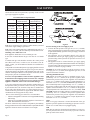
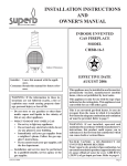
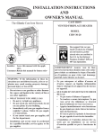
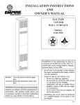
INSTALLATION INSTRUCTIONS
AND
OWNER'S MANUAL
The White Mountain
Vented Slope Glaze Burner
VENTED DECORATIVE LOG SET
FOR INSTALLATION IN
SOLID-FUEL BURNING FIREPLACES
MODELS
VSM-18-1
VSR-18-1
VSM-24-1
VSR-24-1
VSM-30-1
VSR-30-1
WARNING: If the information in these instructions are not followed exactly, a fire or explosion
may result causing property damage, personal
injury or loss of life.
— Do not store or use gasoline or other flammable vapors and liquids in the vicinity of this or
any other appliance.
— WHAT TO DO IF YOU SMELL GAS
• Do not try to light any appliance.
• Do not touch any electrical switch; do not
use any phone in your building.
• Immediately call your gas supplier from a
neighbor’s phone. Follow the gas supplier’s instructions.
• If you cannot reach your gas supplier, call
the fire department.
— Installation and service must be performed
by a qualified installer, service agency or the
gas supplier.
WARNING: This log set is to be installed only in
a solid-fuel burning fireplace with a working flue
constructed of non-combustible material. The vent
damper must also have a damper clamp attached
to it to keep the damper from accidentally closing
during operation.
WARNING: If not installed, operated and maintained in accordance with the manufacturer's
instructions, this product could expose you to
substances in fuel or from fuel combustion which
can cause death or serious illness.
Installer: Leave this manual with the appliance.
Consumer: Retain this manual for future reference.
AVERTISSEMENT: Assurez vous de bien suivre les
instructions données dans cette notice pour réduire
au minimum le risque d’incendie ou d’explosion ou
pour éviter tout dommage matériel, toute blessure
ou la mort.
— Ne pas entreposer ni utiliser d’essence ni d’autres
vapeurs ou liquides inflammables dans le voisnage
de cet appareil ou de tout autre appareil.
— QUE FAIRE SI VOUS SENTEZ UNE ODEUR
DE GAZ:
• Ne pas tenter d’allumer d’appareil.
• Ne touchez a aucun interrupteur. Ne pas vous
servir des téléphones se trouvant dans le bâtiment où vous vous trouvez.
• Appelez immédiatement votre fournisseur de
gaz depuis un voisin. Suivez les instructions du
fournisseur.
• Si vous ne pouvez rejoindre le fournisseur de
gaz, appelez le service des incendies.
— L’installation et l’entretien doivent être assurés
par un installateur ou un service d’entretien
qualifié ou par le fournisseur de gaz.
Page 1
TABLE OF CONTENTS
Section
Page
Important Safety Information .........................................................................................................................3
Safety Information for Users of LP Gas ..........................................................................................................4
Introduction .....................................................................................................................................................5
General Information .................................................................................................................................... 5-6
Fireplace Preparation ................................................................................................................................... 6-7
Before Fully Installing the Appliance ..............................................................................................................7
Gas Supply .......................................................................................................................................................8
Placement of Glowing Embers and Lava Rock ...............................................................................................9
Operation Instructions/Flame Appearance ......................................................................................................9
VSM-(18, 24, 30) Lighting Instructions .......................................................................................................10
VSR-(18, 24, 30) Lighting Instructions ........................................................................................................11
Pilot and Main Burner Flame Characteristics................................................................................................12
Wiring ...........................................................................................................................................................13
Cleaning and Servicing ..................................................................................................................................13
Troubleshooting .............................................................................................................................................14
Parts List ........................................................................................................................................................15
Parts View ......................................................................................................................................................16
How to Order Repair Parts ............................................................................................................................16
Propane (LP) Gas Conversion Instructions ...................................................................................................17
Natural Gas Conversion Instructions .............................................................................................................18
Service Notes .................................................................................................................................................19
CAUTION: If logs or branches are damaged do not use.
A certain amount of sooting will occur which enhances the realistic look of the logs and branches.
If an excessive amount of sooting does occur you can use a gas log cleaner to remove the soot
build-up or lightly brush off the soot build-up with a soft bristle brush taking care not to damage
the logs and branches.
Page 2
14015-6-0907
IMPORTANT SAFETY INFORMATION
Installer: Please leave these instructions with the owner for future
reference.
This unit complies with ANSI Z21.60and CGA 2.26 Decorative
Gas Appliances For Installation In Solid Fuel Burning Fireplaces.
Do not burn wood or solid fuels in a fireplace where a decorative
gas log set is installed. This appliance is for installation only in a
solid fuel burning fireplace, masonry fireplace or manufactured
fireplace.
2.
3.
WARNING: Any modification to this gas log set or to controls
can be dangerous. Improper installation or use of the gas log set
can cause serious injury or death from fire, burns, explosion or
carbon monoxide poisoning.
1.
Please follow all local codes regarding installation, combustion
and ventilation air or in the absence of local codes follow the
National Fuel Gas Code ANSI Z223.1(U.S. installation), or
CAN/CGA-B149, Installation Code (Canada installation).
4.
5.
Proper installation, burner pan location and log placement is
important to achieve optimum look and performance of your
gas log set. The logs have been designed for easy location
and placement on the grate and must be followed for proper
operation.
Do not operate this log set with glass doors in the closed
position. A fireplace screen must be in place when the log
set is burning. Adequate combustion air must be provided for
proper venting. All flames should go up and out the top of the
firebox into the flue vent. If any flames float or curl forward
into the room do not operate appliance. Check for an open
flue and adequate combustion air into the room. A damper
clamp must be installed on the firebox damper to maintain
an open flue vent condition.
Young children must be carefully supervised when they are
in the same room as the gas log while in operation. Do not
place stockings, clothing or any flammable material above
or near the fireplace.
Do not substitute or use materials other than those supplied
for use with the log set.
DO NOT OPERATE THIS GAS LOG SET WITH GLASS DOORS CLOSED.
• Due to high temperatures the appliance should be located
out of traffic and away from furniture and draperies.
• Children and adults should be alerted to the hazards of
high surface temperatures and should stay away to avoid
burns or clothing ignition.
• Young children should be carefully supervised when they
are in the same room as the appliance.
• Clothing or other flammable material should not be placed
on or near the appliance.
• Do not place trash or other articles on the log set during
operation.
• During manufacturing, fabricating and shipping, various
components of this appliance are treated with certain
oils, films or bonding agents. These bonding agents are
not harmful but may produce annoying smoke and
smells as they are burned off during initial operation of
the appliance. This is a normal temporary occurrence.
A window should be opened during the initial bake out
period.
• Keep burner and control compartment clean.
• WARNING: Before installing in a solid fuel burning
fireplace, the chimney flue and firebox must be cleaned
of soot, creosote, ashes and loose paint by a qualified
chimney cleaner.
• WARNING: Do not allow fans to blow directly into
the fireplace. Avoid any drafts that alter burner flame
patterns.
• WARNING: Do not use a blower insert, heat exchanger
insert or other accessory not approved for use with this
appliance.
14015-6-0907
• Installation and repair should be done by a QUALIFIED
SERVICE PERSON. The appliance should be inspected
before use and at least annually by a qualified service
person. More frequent cleaning may be required due to
excessive lint from carpeting, bedding materials, etc. It
is imperative that control compartments, burners and
circulating air passageways of the appliance be kept
clean.
• DO NOT put anything around the fireplace that will
obstruct the flow of ventilation air.
• DO keep the appliance area clear and free from
combustible material, gasoline and other flammable
vapors and liquids.
• A yearly examination and cleaning of the venting system
of the solid-fuel burning fireplace must be performed by
a qualified agency.
• DO make a periodic visual check of pilot and burners.
Clean and replace damaged parts.
• DO NOT use this appliance if any part has been under
water. Immediately call a qualified service technician
to inspect the appliance and to replace any part of the
control system and any gas control which has been under
water.
• Ne pas se servir de cet appareil s'il a été plongé dans
l'eau, complètement ou en partie. Appeler un technicien
qualifié pour inspecter l'appareil et remplacer toute partie
du système de contrôle et toute commande qui ont été
plongés dans l'eau.
Page 3
SAFETY INFORMATION FOR USERS OF LP-GAS
Propane (LP-Gas) is a flammable gas which can cause fires
and explosions. In its natural state, propane is odorless and
colorless. You may not know all the following safety precautions which can protect both you and your family from an
accident. Read them carefully now, then review them point
by point with the members of your household. Someday when
there may not be a minute to lose, everyone's safety will depend
on knowing exactly what to do. If, after reading the following
information, you feel you still need more information, please
contact your gas supplier.
LP-GAS WARNING ODOR
•
•
•
•
If a gas leak happens, you should be able to smell the gas because of the odorant put in the LP-Gas.
That's your signal to go into immediate action!
• Use your neighbor's phone and call a trained LP-Gas service
Do not operate electric switches, light matches, use your
person and the fire department. Even though you may not
phone. Do not do anything that could ignite the gas.
continue to smell gas, do not turn on the gas again. Do not
Get everyone out of the building, vehicle, trailer, or area. Do
re-enter the building, vehicle, trailer, or area.
that IMMEDIATELY.
Close all gas tank or cylinder supply valves.
• Finally, let the service man and firefighters check for escaped
LP-Gas is heavier than air and may settle in low areas such
gas. Have them air out the area before you return. Properly
as basements. When you have reason to suspect a gas leak,
trained LP-Gas service people should repair the leak, then
keep out of basements and other low areas. Stay out until
check and relight the gas appliance for you.
firefighters declare them to be safe.
NO ODOR DETECTED - ODOR FADE
Some people cannot smell well. Some people cannot smell the
odor of the chemical put into the gas. You must find out if you
can smell the odorant in propane. Smoking can decrease your
ability to smell. Being around an odor for a time can affect your
sensitivity or ability to detect that odor. Sometimes other odors
in the area mask the gas odor. People may not smell the gas odor
or their minds are on something else. Thinking about smelling a
gas odor can make it easier to smell.
The odorant in LP-gas is colorless, and it can fade under some
circumstances. For example, if there is an underground leak, the
movement of the gas through soil can filter the odorant. Odorants
in LP-Gas also are subject to oxidation. This fading can occur if
there is rust inside the storage tank or in iron gas pipes.
The odorant in escaped gas can adsorb or absorb onto or into walls,
masonry and other materials and fabrics in a room. That will take
some of the odorant out of the gas, reducing its odor intensity.
LP-Gas may stratify in a closed area, and the odor intensity could
vary at different levels. Since it is heavier than air, there may be
more odor at lower levels. Always be sensitive to the slightest gas
odor. If you detect any odor, treat it as a serious leak. Immediately
go into action as instructed earlier.
SOME POINTS TO REMEMBER
•
Learn to recognize the odor of LP-gas. Your local LP-Gas
Dealer can give you a "Scratch and Sniff" pamphlet. Use it
to find out what the propane odor smells like. If you suspect
that your LP-Gas has a weak or abnormal odor, call your
LP-Gas Dealer.
•
If you are not qualified, do not light pilot lights, perform
service, or make adjustments to appliances on the LP-Gas
system. If you are qualified, consciously think about the odor
of LP-Gas prior to and while lighting pilot lights or performing service or making adjustments.
•
Sometimes a basement or a closed-up house has a musty
smell that can cover up the LP-Gas odor. Do not try to light
pilot lights, perform service, or make adjustments in an area
where the conditions are such that you may not detect the
odor if there has been a leak of LP-Gas.
•
Odor fade, due to oxidation by rust or adsorption on walls
of new cylinders and tanks, is possible. Therefore, people
should be particularly alert and careful when new tanks or
cylinders are placed in service. Odor fade can occur in new
tanks, or reinstalled old tanks, if they are filled and allowed
Page 4
to set too long before refilling. Cylinders and tanks which
have been out of service for a time may develop internal rust
which will cause odor fade. If such conditions are suspected
to exist, a periodic sniff test of the gas is advisable. If you
have any question about the gas odor, call your LP-gas
dealer. A periodic sniff test of the LP-gas is a good safety
measure under any condition.
•
If, at any time, you do not smell the LP-Gas odorant and you
think you should, assume you have a leak. Then take the same
immediate action recommended above for the occasion when
you do detect the odorized LP-Gas.
•
If you experience a complete "gas out," (the container is under no vapor pressure), turn the tank valve off immediately.
If the container valve is left on, the container may draw in
some air through openings such as pilot light orifices. If this
occurs, some new internal rusting could occur. If the valve is
left open, then treat the container as a new tank. Always be
sure your container is under vapor pressure by turning it off
at the container before it goes completely empty or having it
refilled before it is completely empty.
14015-6-0907
INTRODUCTION
Product Components
• Burner Pan Assembly
— "M" model includes manual gas valve, regulator and safety
pilot.
— "R" model includes millivolt valve and safety thermopile
generator and on/off switch. A remote control or wall switch
accessory is available as an option for this model.
• 1 Bag of Glowing Embers (Rock Wool)
• 1 Damper Clamp
• 2 Bags Decorative Rock
Always consult your local Building Department regarding regulations, codes or ordinances which apply to the installation of a vented
decorative gas log set in a solid-fuel burning fireplace.
This appliance is only for use with the type of gas indicated on
the rating plate.
Instructions to Installer
1. Installer must leave instruction manual with owner after
installation.
2. Installer must have owner fill out and mail warranty card supplied
with the fireplace.
3. Installer should show owner how to start and operate the
fireplace.
WARNING: ANY CHANGE TO THIS APPLIANCE OR ITS
CONTROLS CAN BE DANGEROUS.
Improper installation or use of the appliance can cause serious injury or death from fire, burns, explosion or carbon
monoxide poisoning.
GENERAL INFORMATION
This series is design certified in accordance with American National Standard/CSA Standard Z21.60 and CGA 2.26, respectively, by the
Canadian Standards Association as a Vented Decorative Appliance and should be installed according to these instructions.
Any alteration of the original design, installed other than as shown in these instructions or use with a type of gas not shown on
the rating plate is the responsibility of the person and company making the change.
Important
All correspondence should refer to complete Model Number, Serial Number and type of gas.
Notice: During initial use of the logs and branches you will detect an odor as the logs and branches are cured.
Specifications (Figure 1)
Model
Input
Btuh
** Reduced
Input
BTUH
40,000
50,000
60,000
40,000
50,000
60,000
Minimum
Front
Width
32"
34"
38"
28"
30"
34"
Depth
Height
VSM-18*
VSM-24*
VSM-30*
VSR-18†
VSR-24†
VSR-30†
65,000
75,000
75,000
65,000
75,000
75,000
15"
15"
15"
15"
15"
15"
22"
22"
22"
22"
22"
22"
Model
Input
KW/H
**Reduced
Input
BTUH
Depth
(cm)
Height
(cm)
19.0
21.9
21.9
19.0
21.9
21.9
11.7
14.6
17.5
11.7
14.6
17.5
Minimum
Front
Width
(cm)
81.3
86.4
96.5
71.1
76.2
86.4
VSM-18*
VSM-24*
VSM-30*
VSR-18†
VSR-24†
VSR-30†
38.1
38.1
38.1
38.1
38.1
38.1
55.8
55.8
55.8
55.8
55.8
55.8
*M
Denotes manual gas valve
†R
Denotes millivolt gas valve
**
Attention: An additional main burner orifice is provided
in instruction package envelope to reduce the input of the burner
assembly.
14015-6-0907
Gas Inlet VSM Models
Gas Inlet VSR Models
3/8" (9.5mm)
3/8" (9.5mm)
Accessories for VSM and VSR Models
Embers Kit
EK-1
Accessories for VSR Models
Battery Operated Remote Control
Electric Remote
Wall Switch
FRBC
FREC
FWS
Figure 1
Page 5
GENERAL INFORMATION (continued)
Qualified Installing Agency
Installation and replacement of gas piping, gas utilization equipment or accessories and repair and servicing of equipment shall be
performed only by a qualified agency. The term "qualified agency"
means any individual, firm, corporation or company which either
in person or through a representative is engaged in and is responsible for (a) the installation or replacement of gas piping or (b) the
connection, installation, repair or servicing of equipment, who is
experienced in such work, familiar with all precautions required
and has complied with all the requirements of the authority having
jurisdiction.
State of Massachusetts: The installation must be made by
a licensed plumber or gas fitter in the Commonwealth of
Massachusetts.
The installation and the provisions for combustion and ventilation
air must conform with the National Fuel Gas Code, ANSI Z223.1/
NFPA54* Canadian Installation Code CAN/CGA B149.
*Available from the American National Standards Institute, Inc. 11 West 42nd St.,
New York, N.Y. 10018.
High Altitude Installation
When installing this unit at an elevation above 2000 feet (in the
United States) it may be necessary to decrease the input rating by
changing the existing burner orifice to a smaller size. Generally,
input should be reduced 4 percent for each 1000 feet above sea
level. However, if the heating value of the gas has been reduced,
this general rule may not apply. Check with local gas utility for
proper orifice size identification.
For Canadian high altitude applications, this appliance is suitable for
installation at elevations between 0 feet (0m) and 4,500 (1,370m)
without change.
When installing this unit at an elevation above 4500 feet (1,370m)
(in Canada), check with local authorities.
Consult your local gas utility for assistance in determining the
proper orifice for location.
FIREPLACE PREPARATION
• Turn off gas supply to fireplace or firebox.
• Have the fireplace floor and chimney professionally cleaned to
remove ashes, soot, creosote or other obstructions.
Have this cleaning performed annually after installation.
• Seal any fresh air vents or ash clean-out doors located on floor
or wall of fireplace. If not, drafting may cause pilot
outage or sooting. Use a heat-resistant sealant. Do not seal
chimney flue damper.
Installing Damper Clamp (Figure 2)
Remove all ashes or other debris from the fireplace. If the fireplace is equipped with an ash dump be sure to seal the door with
furnace cement or high temperature silicone. Be sure to check the
damper for proper operation and verify that the flue passageway
is open. Attach damper clamp to the vent damper and tighten hold
down bolt.
Place the clamp over the lip of the damper and tighten the hold
down bolt until the clamp is securely attached to the damper. This
will prevent the damper from accidentally closing.
Figure 2
State of Massachusetts requirement for installation of vented
decorative appliance in a vented fireplace is the following:
In the Commonwealth of Massachusetts vent free products are
not approved.
A vented decorative gas appliance must be installed in a vented
fireplace only in the state of Massachusetts. The vent damper
must be removed or welded permanently open.
Page 6
14015-6-0907
FOR FACTORY BUILT FIREPLACES
FREE OPENING AREA OF CHIMNEY DAMPER FOR VENTING COMBUSTION PRODUCTS FROM DECORATIVE APPLIANCES FOR INSTALLATION IN SOLID FUEL BURING
FIREPLACES.
FOR MASONRY BUILT FIREPLACES
FREE OPENING AREA OF CHIMNEY DAMPER FOR VENTING COMBUSTION PRODUCTS FROM DECORATIVE APPLIANCES FOR INSTALLATION IN SOLID FUEL BURING
FIREPLACES.
Appliance Input Rate (kBTU/hr)
Appliance Input Rate (kBTU/hr)
20
Chimney
Height*
(ft)
30
40
50
60
70
20
80
Chimney
Height*
(ft)
Minimum Opening** (sq. in.)
50
60
70
80
Minimum Opening** (sq. in.)
11.3
16.6
22.1
28.3
35.3
44.2
-
6
17.6
25.7
33.8
41.7
49.2
56.6
64.0
15
8.6
12.6
17.3
21.2
26.4
32.2
31.2
8
16.5
23.7
31.2
38.7
45.5
52.4
59.7
20
7.5
10.8
14.5
18.1
22.1
26.4
31.2
10
15.1
21.7
28.7
35.2
41.7
48.2
54.3
25
6.6
9.6
12.6
15.9
18.1
22.9
27.3
15
14.1
19.9
26.1
32.0
37.7
43.2
48.8
30
6.2
9.1
11.3
14.5
17.3
20.4
24.6
20
12.9
18.5
23.7
28.8
34.3
39.8
44.4
35
5.7
8.0
10.8
13.2
15.9
18.9
22.1
30
12.2
16.9
21.6
26.5
31.2
35.9
40.3
40
5.3
7.5
10.2
12.6
15.2
18.1
20.4
5.9
8.8
Chimney
Height*
(m)
**
40
10
Appliance Input Rate KW/HR)
Appliance Input Rate KW/HR)
*
30
11.7
14.6
17.6
20.5
5.9
Chimney
Height*
(m)
23.4
Minimum Opening** (sq. in.)
8.8
11.7
14.6
17.6
20.5
23.4
Minimum Opening** (sq. in.)
1.83
113.6
165.8
218.1
269.0
317.4
365.2
412.9
3.05
72.9
107.1
142.6
182.6
227.8
285.2
-
2.44
106.5
152.9
201.3
249.7
293.6
338.1
385.2
4.57
55.5
81.3
111.6
136.8
170.3
207.8
248.4
3.05
97.4
140.0
185.2
227.1
269.0
311.0
350.3
6.10
48.4
69.7
93.6
116.8
142.6
170.3
201.3
4.57
91.0
128.4
168.4
206.5
243.2
278.7
314.8
7.62
42.6
61.9
81.3
102.6
116.8
147.8
176.1
6.10
83.2
119.4
152.9
185.8
221.3
256.8
286.5
9.14
40.0
58.7
72.9
93.6
111.6
131.6
158.7
9.14
78.7
109.0
139.4
171.0
201.3
231.6
260.0
10.67
36.8
51.6
69.7
85.2
102.6
121.9
142.6
12.19
34.2
48.4
65.8
81.3
98.1
116.8
131.6
Height is from hearth to top of chimney and the minimum height is
10 feet (3.05m).
Chart shows minimum opening (sq. in.) (cm2) for given height and
input rate.
*
**
Height is from hearth to top of chimney and the minimum height is
6 feet (1.83m).
Chart shows minimum opening (sq. in.) (cm2) for given height and
input rate.
BEFORE FULLY INSTALLING THE APPLIANCE
Before installing in a solid fuel burning fireplace, the chimney flue
and firebox must be cleaned of soot, creosote, ashes and loose paint
by a qualified chimney cleaner.
You must secure the gas log heater to the fireplace floor. If
not, the entire unit may move when you adjust the controls.
Movement of unit may cause shifting of the gas logs which
leads to sooting and improper burning. Grate movement
could cause a gas leak.
Special care is required if you are installing the unit into a
sunken fireplace. You must raise the fireplace floor to allow
access to gas log controls. This will insure adequate air flow
and guard against sooting. Raise the fireplace floor using
noncombustible materials.
1.
2.
Center the gas log in the fireplace or firebox. The grates must
clear the fireplace or firebox screen.
An anchor hole is provided in the two bottom side members
of the grate frame. After centering the grate correctly, mark
the hole positions on the fireplace/firebox floor. Drill two (2)
5/32" diameter holes approximately 1-1/2" deep for masonry
screws or 1/8" hole for sheet metal screws.
14015-6-0907
3.
Anchor the grate to the fireplace/firebox floor using the screws
provided.
Proper installation of the grate is essential to prevent any movement of the gas logs and controls during operation.
Figure 3
Page 7
GAS SUPPLY
Check all local codes for requirements, especially for the size and
type of gas supply line required.
Recommended Gas Pipe Diameter
Pipe Length
Schedule 40 Pipe
Tubing, Type L
Inside Diameter
Outside Diameter
Nat.
L.P.
Nat.
L.P.
0-10 feet
1/2”
3/8”
1/2”
3/8”
0-3 meters
12.7mm 9.5mm 12.7mm 9.5mm
10-40 feet
1/2”
1/2”
5/8”
1/2”
4-12 meters 12.7mm 12.7mm 15.9mm 12.7mm
40-100 feet
1/2”
1/2”
3/4”
1/2”
13-30 meters 12.7mm 12.7mm
19mm 12.7mm
100-150 feet
3/4”
1/2”
7/8”
3/4”
31-46 meters 19mm 12.7mm 22.2mm 19mm
Note: Never use plastic pipe. Check to confirm whether your local
codes allow copper tubing or galvanized.
Note: Since some municipalities have additional local codes, it is
always best to consult your local authority and installation code.
Installing a New Main Gas Cock
Each appliance should have its own manual gas cock.
In the state of Massachusetts the gas cock must be a T handle
type.
A manual main gas cock should be located in the vicinity of the
unit. Where none exists, or where its size or location is not adequate, contact your local authorized installer for installation or
relocation.
Compounds used on threaded joints of gas piping shall be resistant
to the action of liquefied petroleum gases. The gas lines must be
checked for leaks by the installer. This should be done with a soap
solution watching for bubbles on all exposed connections, and if
unexposed, a pressure test should be made.
Never use an exposed flame to check for leaks. Appliance must
be disconnected from piping at inlet of control valve and pipe
capped or plugged for pressure test. Never pressure test with
appliance connected; control valve will sustain damage!
A gas valve and ground joint union should be installed in the gas
line upstream of the gas control to aid in servicing. It is required
by the National Fuel Gas Code that a drip line be installed near
the gas inlet. This should consist of a vertical length of pipe tee
connected into the gas line that is capped on the bottom in which
condensation and foreign particles may collect.
The use of the following gas connectors is recommended:
— ANS Z21.24 Appliance Connectors of Corrugated Metal Tubing
and Fittings
— ANS Z21.45 Assembled Flexible Appliance Connectors of
Other Than All-Metal Construction
The above connectors may be used if acceptable by the authority
having jurisdiction. The state of Massachusetts requires that a flexible
appliance connector cannot exceed three feet in length.
Page 8
Figure 4
Pressure Testing of the Gas Supply System
1. To check the inlet pressure to the gas valve, a 1/8" (3.175mm)
N.P.T. plugged tapping, accessible for test gauge connection, must
be placed immediately upstream of the gas supply connection
to the appliance.
2. The appliance and its individual shutoff valve must be
disconnected from the gas supply piping system during any
pressure testing of that system at test pressures in excess of 1/2
psig (3.5 kPa).
3. The appliance must be isolated from the gas supply piping
system by closing its individual manual shutoff valve during any
pressure testing of the gas supply piping system at test pressures
equal to or less than 1/2 psig (3.5 kPa).
Attention! If one of the procedures results in pressures in excess
of 1/2 psig (14" w.c.) (3.5 kPa) on the appliance gas valve, it will
result in a hazardous condition.
Checking Manifold Pressure
VSR Natural gas models will have a manifold pressure of approximately 3.5" w.c. (.871kPa) at the pressure regulator outlet
with the inlet pressure to the pressure regulator from a minimum
of 4.5" w.c. (1.120kPa) for the purpose of input adjustment to a
maximum of 10.5" w.c. (2.615kPa). VSM Natural gas models will
have a manifold pressure of approximately 4.5" w.c. (1.12kPa) at
the pressure regulator outlet with the inlet pressure to the pressure
regulator from a minimum of 7.0" w.c. (1.74kPa) for the purpose
of input adjustment to a maximum of 10.5" w.c. (2.615kPa). VSR
and VSM Propane gas models will have a manifold pressure approximately 10.0" w.c. (2.49kPa) at the pressure regulator outlet
with the inlet pressure to the pressure regulator from a minimum
of 11.0" w.c. (2.739kPa) for the purpose of input adjustment to a
maximum of 13.0" w.c. (3.237kPa).
VSM
Note: A test gage connection is located downstream of the gas
appliance pressure regulator for measuring gas pressure. The connection is a 1/8 inch 3mm) N.P.T. plugged tapping.
VSR
Note: The gas control is equipped with a captured screw type pressure test point, therefore it is not necessary to provide a 1/8" test
point up stream of the control.
14015-6-0907
PLACEMENT OF GLOWING EMBERS AND LAVA ROCK
Placement of the glowing embers (rock wool) is very individual
and light coverage of the areas indicated will provide your best
effects. We recommend separation of the rock wool by hand and
make your coverage as light and fluffy as possible.
Place just enough embers on the burner to obtain the glow and a
gold, yellow flame.
Do not place embers (rock wool) over large ports in rear portion
of burner.
Rock wool should not be placed in the area of the pilot assembly.
Placing Lava Rock in Front of Burner on Fireplace Floor
Spread lava rocks on fireplace floor in front of the burner pan.
The lava rocks are for decorative effect and are not required for
fireplace operation.
ATTENTION: DO NOT PLACE LAVA ROCKS ON BURNER, LOGS OR ROCK WOOL. THE LAVA ROCKS SHOULD
ONLY BE PLACED ON THE FIREPLACE FLOOR.
Figure 5
OPERATION INSTRUCTIONS/FLAME APPEARANCE
Flames from the pilot (right back side of the pan burner) as well
as the main flame should be visually checked as the log set is
installed.
In normal operation at full rate after 10 to 15 minutes, the flame
appearance should be sets of yellow flames.
NOTE: all flames will be random by design, flame height will go
up and down.
Avoid any drafts that alter burner flame patterns. Do not allow fans
to blow directly into fireplace. Do not place a blower inside the
burner area of the firebox. Ceiling fans may create drafts that alter
flame patterns. Sooting and improper burning will result.
During manufacturing, fabricating and shipping, various
components of this appliance are treated with certain oils, films or
bonding agents. These chemicals are not harmful, but may produce
annoying smoke and smells as they are burned off during the initial
operation of the appliance, possibly causing headaches or eye or
lung irritation. This is a normal and temporary occurrence.
Manual - Figure 6
The initial break-in operation should last 2-3 hours with the burner
at the highest setting. Provide maximum ventilation by opening
windows or doors to allow odors to dissipate. Any odors remaining
after this initial break-in will be slight and will disappear with
continued use.
Millivolt - Figure 7
14015-6-0907
Page 9
VSM-(18, 24, 30) LIGHTING INSTRUCTIONS
FOR YOUR SAFETY READ BEFORE LIGHTING
WARNING: If you do not follow these instructions exactly, a fire or explosion
may result causing property damage, personal injury or loss of life.
A. This appliance has a pilot which must be lighted by
hand. When lighting the pilot, follow these instructions
exactly.
B. BEFORE LIGHTING smell all around the appliance area
for gas. Be sure to smell next to the floor because some
gas is heavier than air and will settle on the floor.
WHAT TO DO IF YOU SMELL GAS
• Do not try to light any appliance.
• Do not touch any electrical switch;
do not use any phone in your building.
• Immediately call your gas supplier from a neighbor's
phone. Follow the gas supplier's instructions.
• If you cannot reach your gas supplier, call the fire
department.
C. Use only your hand to push in or turn the gas control
knob. Never use tools. If the knob will not push in or turn
by hand, don't try to repair it; call a qualified service
technician. Force or attempted repair may result in a fire
or explosion.
D. Do not use this appliance if any part has been under water.
Immediately call a qualified service technician to inspect
the appliance and to replace any part of the control system
and any gas control which has been under water.
LIGHTING INSTRUCTIONS
WARNING
• Any glass doors shall be opened when the appliance is in operation.
• A fireplace screen must be in place when the appliance is operating and, unless other provisions for
combustion air are provided, the screen shall have an opening(s) for introduction of combustion air.
1. S T O P !
R e a d
the safety information
above.
GAS CONTROL
KNOB SHOWN IN
"OFF" POSITION
2. Push in manual gas control
knob slightly and turn
clockwise
to
"OFF". Do not force.
NOTE: Knob cannot be
turned from "PILOT"
to "OFF" unless knob is
pushed in slightly. Do not
force.
3. Wait ten (10) minutes to clear out any gas.
Then smell for gas, including near the floor. If you
smell gas, STOP! Follow “B” in the safety information
above. If you don't smell
gas, go to the next step.
5. Turn manual gas control knob counterclockwise
to “PILOT.”
6. Push in control knob all the way and hold
in. Immediately light the pilot with a match and the
lighter rod that is provided with the burner. Continue
to hold the control knob in for about one (1) minute
after the pilot is lit. Release knob and it will pop back
up. Pilot should remain lit. If it goes out, repeat steps
2 through 6.
• If knob does not pop up when released, stop and
immediately call a qualified service technician or
gas supplier.
• If the pilot will not stay lit after several tries, turn
the gas control knob to “OFF” and call your service
technician or gas supplier.
7. Turn manual gas control knob counterclockwise
to “ON.”
4. F i n d p i l o t f o llow metal tube from gas
control. The pilot is in
front of middle log on the
right side.
TO TURN OFF GAS TO APPLIANCE
1. Push in gas control knob slightly and turn
clockwise
to “OFF.” Do not force.
Page 10
14015-6-0907
VSR-(18, 24, 30) LIGHTING INSTRUCTIONS
FOR YOUR SAFETY READ BEFORE LIGHTING
WARNING: If you do not follow these instructions exactly, a fire or explosion
may result causing property damage, personal injury or loss of life.
A. This appliance has a pilot which must be lighted by
hand. When lighting the pilot, follow these instructions
exactly.
B. BEFORE LIGHTING smell all around the appliance
area for gas. Be sure to smell next to the floor because
some gas is heavier than air and will settle on the
floor.
WHAT TO DO IF YOU SMELL GAS
• Do not try to light any appliance.
• Do not touch any electrical switch;
do not use any phone in your building.
• Immediately call your gas supplier from a neighbor's
phone. Follow the gas supplier's instructions.
• If you cannot reach your gas supplier, call the fire
department.
C. Use only your hand to push in or turn the gas control
knob. Never use tools. If the knob will not push in or
turn by hand, don't try to repair it; call a qualified
service technician. Force or attempted repair may
result in a fire or explosion.
D. Do not use this appliance if any part has been under
water. Immediately call a qualified service technician
to inspect the appliance and to replace any part of the
control system and any gas control which has been
under water.
LIGHTING INSTRUCTIONS
WARNING
• Any glass doors shall be opened when the appliance is in operation.
• A fireplace screen must be in place when the appliance is operating and, unless other provisions for combustion air
are provided, the screen shall have an opening(s) for introduction of combustion air.
1. S T O P ! R e a d t h e
information above.
safety
2. Set the ON/OFF switch to
"OFF".
GAS CONTROL
KNOB SHOWN
IN "OFF" POSITION
3. Turn off all electric power to the
appliance (if applicable).
4. P u s h i n g a s c o n t ro l k n o b
slightly and turn clockwise
to "OFF".
5. W a i t t e n ( 1 0 ) m i n u t e s
to clear out any gas. Then smell
for gas, including near the floor. If
you smell gas, STOP! Follow "B"
in the safety information above. If
you don't smell gas, go to the next
step.
NOTE: Knob cannot be turned
from "PILOT" unless knob is
pushed in slightly. Do not force.
6. Find pilot - follow metal
tube from gas control. The pilot is
in front of middle log on the right
side.
7. Tu r n g a s c o n t ro l k n o b c o u n t e rc l o c k w i se
to "PILOT."
8. Push in gas control knob all the way and
hold in. Immediately light the pilot with a match and
lighter rod that is provided with the burner. Continue
to hold the control knob in for about one (1) minute
after the pilot is lit. Release knob, and it will pop back
up. Pilot should remain lit. If it goes out, repeat steps
4 through 8.
• If knob does not pop up when released, stop and
immediately call your qualified service technician
or gas supplier.
• If the pilot will not stay lit after several tries, turn
the gas control knob to "OFF" and call your service
technician or gas supplier.
to
9. Turn gas control knob counterclockwise
"ON."
10. Set the ON/OFF switch to "ON".
TO TURN OFF GAS TO APPLIANCE
1. Set the ON/OFF switch to "OFF".
2. Push in gas control knob slightly and turn
14015-6-0907
clockwise
to "OFF". Do not force.
Page 11
PILOT AND MAIN BURNER FLAME CHARACTERISTICS
Pilot Flame Pattern (Figure 9)
Figure 8 shows a correct pilot flame pattern. The correct flame will be blue and will extend beyond the thermocouple/thermopile. The
flame will surround the thermocouple/thermopile just below the tip. A slight yellow flame may occur where the pilot flame and main
burner flame meet.
After use, cleaning of the pilot burner may be required for the proper flame. The pilot orifice can be cleaned with high pressure air or
by placing under running water. Pilot orifice must be dry before replacement. Use a pipe cleaner to clean inside the pilot after the pilot
orifice has been removed.
To Remove Pilot Orifice
1. Disconnect the pilot supply line at the pilot burner.
2. Remove pilot orifice from pilot burner. It may be necessary to tap on pilot burner in order to remove the pilot orifice.
Pilot Flame Pattern
Figure 9
If pilot flame pattern is incorrect
• See Troubleshooting, page 15
Main Burner Flame Pattern
The main burner flame will be completely yellow.
Main Burner Flame Ignition and Extinction
When the main burner is ignited it will take a few seconds for the full flame pattern to develop.
When the main burner is extinguished it will take a few seconds for the flames to disappear. It is normal to have the flames burn down
near the rock wool, as the remaining gas is burned.
Page 12
14015-6-0907
WIRING
Thermostats are not approved on vented decorated
appliances.
Label all wires prior to disconnection when servicing controls.
Wiring errors can cause improper and dangerous operation. Verify
proper operation after servicing.
VSR gas valve does not require 24 or 110 volts. See Figure 10 to
provide optional wall switch or remote control.
It is important to use wire of a gauge proper for the length of the
wire:
2. When facing the appliance, the remote receiver must be placed
in the right side firebox, toward the front.
Note: Do not let remote control receiver come in contact with
burner assembly.
Refer to remote control installation and operating instructions for
more details on remote control.
VSR Wiring Diagram (Figure 10)
RECOMMENDED WIRE GAUGES
Maximum Length
Wire Gauge
1' to 10'
18
10' to 25'
16
25' to 35'
14
Use the two leads (black wires) from ON/OFF switch to attach
optional components.
Check System Operation
Millivolt system and all individual components may be checked
with a millivolt meter 0-1000 MV range.
750 Millivolt System
When you ignite the pilot, the thermocouple produces millivolts
(electrical current) which energizes the magnet in the gas valve.
After 30 seconds to 1 minute time period you can release the gas
control knob and the pilot will stay ON. Allow your pilot flame to
operate an additional one (1) to two (2) minutes before you turn the
gas control knob from the PILOT position to the ON position. This
time period allows the millivolts (electrical current) to buildup to a
sufficient level allowing the gas control to operate properly.
Millivolt Control
The valve regulator controls the burner pressure which should be
checked at the pressure test point. Turn captured screw counter
clockwise 2 or 3 turns and then place tubing to pressure gauge over
test point (Use test point “A” closest to control knob). After taking
pressure reading, be sure and turn captured screw clockwise firmly
to re-seal. Do not over torque. Check for gas leaks.
Remote Receiver -VSR-(18, 24, 30)
Use the following steps to place the remote receiver adjacent to
the gas valve.
Attention:
1. The remote receiver can not be placed behind the gas valve
and burner assembly.
Figure 10
VSR
Note: (Wiring harness located in envelope)
Connect the 2 - 1/4" terminals onto the TH and TH/TP terminals
on valve. Place decorative log to right of the gas valve and burner
assembly. When connecting to remote receiver, cut off 1/4" terminals
from wires attached to ON/OFF switch. Strip wires back about
1/4". Connect stripped ends into remote receiver.
CLEANING AND SERVICING
Keep the control compartment, logs and burner area surrounding
the logs clean.
THE LOGS CAN GET VERY HOT— HANDLE ONLY
WHEN COOL.
Always keep the appliance area clear and free from combustible
materials, gasoline, and other flammable vapors and liquids.
Never obstruct the flow of combustion and ventilation air. Keep the
front of the appliance clear of all obstacles and materials.
14015-6-0907
Inspecting Venting System
A vented fireplace venting system is designed and constructed
to develop a positive flow adequate to remove flue gases to the
outside atmosphere.
Any foreign objects in the venting system, may cause spillage of
the flue gases into the room.
Periodic examination and/or cleaning of the venting system of the
solid-fuel burning fireplace must be done by a qualified service
person. Visually inspect the damper and flue area for excessive
soot build-up. This soot (carbon) may be removed by brushing
with a soft bristle brush.
Page 13
TROUBLESHOOTING
SYMPTOMS-POSSIBLE CAUSES AND CORRECTIONS
1. Match will not light pilot.
a. Main shut-off valve closed.
• Make sure that the shut-off valve located on the pipe
supplying gas to the fireplace is open.
b. Air in the gas line.
• Light a match, turn valve knob to "PILOT" position and
depress, keep match near pilot burner until it lights.
c. Valve knob in "OFF" position.
• Turn valve knob to "PILOT" position and depress, keep
match near pilot burner until it lights.
d. Pilot orifice plugged up, not allowing gas to flow.
• This repair requires tools and some degree of experience.
Ask serviceman for assistance.
e. No gas supply to the fireplace.
• Check plumbing to see if gas fireplace has been hooked
up to the gas supply line.
• Propane tanks is empty.
2. Pilot will not stay lit after carefully following lighting instructions for VSR—Models.
a. Defective pilot generator (thermopile), remote wall
switch.
• Check pilot flame. Must impinge on thermopile. Clean
and or adjust pilot for maximum flame impingement on
thermopile.
• Be sure wire connections from thermopile at gas valve
terminals are tight and thermopile is fully inserted into
pilot bracket.
• One of the wall switch wires may be grounded. Remove
wall switch wires from valve terminals if pilot now stays
lit, trace wall switch wiring for ground. May be grounded
to appliance or gas supply.
• Check thermopile with millivolt meter. Take reading at
thermopile terminals of gas valve. Should read 325 millivolts minimum while holding valve knob depressed
in pilot position and wall switch "Off." Replace faulty
thermopile if reading is below specified minimum.
b. Defective automatic valve operator — Turn valve knob to
"On." Place wall switch to "On" millivolt meter should read
greater than 100 M.V. If the reading is okay and the burner
does not come on, replace the gas valve.
c. Defective thermopile.
• Check all connections and try.
• If still not operating, disconnect lead between thermocouple switch and valve operator. Then disconnect lead
to pilot magnet and connect to valve operator terminal
(TP, TH). If pilot remains lit fault lies with thermocouple.
Check that bulb is in proper location. If still not working replace thermocouple (see drawing in manual for
additional information).
Page 14
3. Pilot burning, no gas to burner, valve knob "On," wall
switch "On."
a. Wall switch or wires defective.
• Check wall switch and wires for proper connections.
Jumper wire cross terminals at wall switch, if burner
comes on, replace defective wall switch. If okay, jumper
wires cross wall switch wires at valve, if burner comes
on, wires are faulty or connections are bad.
b. Thermopile may not be generating sufficient millivoltage.
• Replace.
c. Plugged burner orifice.
• Check burner orifice for debris and remove.
4. Pilot will not stay lit after carefully following lighting instructions for VSM—Models.
a. Defective thermocouple.
• Check that pilot flame impinges on thermocouple. Clean
and/or adjust pilot for maximum flame impingement.
• Ensure that the thermocouple connection at the gas valve
is fully inserted and tight (hand tight plus 1/4 turn) faulty
thermopile if reading is below specified minimum.
• Disconnect the thermocouple from the valve, place one
millivolt meter lead wire on the tip of the thermocouple
and the other meter lead wire on the thermocouple
copper lead. Start the pilot and hold the valve knob in.
If the millivolt reading is less than 15 mv, replace the
thermocouple.
b. Defective valve.
• If thermocouple is producing more than 15 millivolts,
replace faulty valve.
5. Frequent pilot outage problem.
a. Pilot flame may be too low or blowing (high) causing the
pilot to drop out.
• Clean and/or adjust flame for maximum flame impingement on thermopile or thermocouple.
6. Main burner flame is too low or too high.
a. Check inlet supply pressure for "M" and "R" models.
b. Check manifold pressure on gas valve for "R" models and
inlet regulator on "M" models.
14015-6-0907
PARTS LIST
Index
Part
No. Number
Description
1
1
1
2
3
5
5
6
7
7
8
8
8
15426
15427
15428
11376
P-271
R-5675
R-5676
15415
R-7158
R-7157
14033
14035
14037
COMMON PARTS
REAR LOG SUPPORT (18)
REAR LOG SUPPORT (24)
REAR LOG SUPPORT (30)
BURNER SUPPORT - LEFT
ORIFICE FITTING
AIR SHUTTER-LPG
AIR SHUTTER-NAT
PILOT BRACKET
PILOT ASSEMBLY-NAT
PILOT ASSEMBLY-LPG
BURNER ASSEMBLY (18)
BURNER ASSEMBLY (24)
BURNER ASSEMBLY (30)
4
4
4
4
4
4
4
4
4
4
9
10
10
NS
NS
NS
NS
NS
NS
NS
NS
NS
NS
NS
P-265
P-209
P-256
P-274
P-257
P-276
P-279
P-280
P-181
P-283
11375
R-7155
R-7156
R-7195
R-5910
R-5699
R-5757
15432
15430
15496
11788
R-2809
R-734
R-1054
VSR-18,24,30
ORIFICE-LPG (18) (40,000 BTU)
ORIFICE-NAT (18) (40,000 BTU)
ORIFICE-LPG (18) (65,000 BTU)
ORIFICE-NAT (18) (65,000 BTU)
ORIFICE-LPG (24&30) (75,000 BTU)
ORIFICE-LPG (24) (50,000 BTU)
ORIFICE-NAT (24&30) (75,000 BTU)
ORIFICE-NAT (24) (50,000 BTU)
ORIFICE-LPG (30) (60,000 BTU)
ORIFICE-NAT (30) (60,000 BTU)
BURNER SUPPORT - RIGHT
GAS VALVE - LPG
GAS VALVE - NAT
BRASS MALE CONNECTOR
SWITCH LOG ASSEMBLY
WIRE HARNESS
ON/OFF SWITCH
TUBING VALVE TO PILOT
TUBING VALVE TO BURNER
ROCK WOOL
DECORATIVE ROCK
DAMPER CLAMP
LIGHTER ROD
THERMOPILE
Index
Part
No. Number
4
4
4
4
4
4
4
4
4
4
11
12
13
13
14
15
16
17
18
19
NS
NS
NS
NS
NS
NS
NS
P-265
P-211
P-256
P-273
P-257
P-276
P-277
P-278
P-181
P-282
11481
15413
R-7159
R-7160
P-133
P-135
P-239
R-7195
R-7278
15494
15431
15429
15496
11788
R-2809
R-734
R-2256
Description
VSM-18,24,30
ORIFICE-LPG (18) (40,000 BTU)
ORIFICE-NAT (18) (40,000 BTU)
ORIFICE-LPG (18) (65,000 BTU)
ORIFICE-NAT (18) (65,000 BTU)
ORIFICE-LPG (24&30) (75,000 BTU)
ORIFICE-LPG (24) (50,000 BTU)
ORIFICE-NAT (24&30) (75,000 BTU)
ORIFICE-NAT (24) (50,000 BTU)
ORIFICE-LPG (30) (60,000 BTU)
ORIFICE-NAT (30) (60,000 BTU)
BURNER SUPPORT - RIGHT
REGULATOR MOUNTING BRACKET
INLET REGULATOR - LPG
INLET REGULATOR - NAT
NIPPLE 2"
3/8" ELBOW
NIPPLE 1 1/2"
BRASS MALE CONNECTOR
GAS VALVE
COVER PLATE
TUBING VALVE TO PILOT
TUBING VALVE TO BURNER
ROCK WOOL
DECORATIVE ROCK
DAMPER CLAMP
LIGHTER ROD
THERMOCOUPLE
USE ONLY MANUFACTURER'S REPLACEMENT PARTS. USE OF ANY OTHER PARTS COULD CAUSE INJURY OR DEATH.
14015-6-0907
Page 15
PARTS VIEW
HOW TO ORDER REPAIR PARTS
Parts can be ordered only through your service person or dealer. For best results, the service person or dealer should order parts through the distributor. Parts can be shipped directly to the service person/dealer.
All parts listed in the Parts List have a Part Number. When ordering parts, first obtain the Model Number from the name plate on your equipment. Then
determine the Part Number (not the Index Number) and the Description of each part from the following appropriate illustration and list. Be sure to give
all this information . . .
Applaince Model Number
Part Description
Appliance Serial Number
Part Number
Type of Gas (Propane or Natural)
Do not order bolts, screws, washers or nuts. They are standard hardware items and can be purchased at any local hardware store.
Shipments contingent upon strikes, fires and all causes beyond our control.
Page 16
Empire Comfort Systems, Inc. Nine Eighteen Freeburg Ave. Belleville, Illinois 62222-0529
14015-6-0907
PROPANE (LP) GAS CONVERSION INSTRUCTIONS
1. If applicable, turn OFF gas supply to vented decorative log
set.
2. If applicable, remove gas supply line from vented decorative
log set.
3. For VSM-(18, 24, 30) only, remove Natural gas inlet regulator
from burner assembly.
3. For VSR-(18, 24, 30) only, remove regulator cap and blue
conversion screw from HI-LO knob on gas valve.
4. For VSM-(18, 24, 30) only, install Propane (LP) gas inlet
regulator marked 10.0 onto burner assembly.
4. For VSR-(18, 24, 30) only, install Propane (LP) gas pink
conversion screw into HI-LO knob on gas valve. Assure that
conversion screw is finger tight (refer to Honeywell conversion
instructions which are included in conversion kit). Install new
regulator cap over pink conversion screw.
5. Remove Natural gas main burner orifice from orifice fitting.
Save the Natural gas main burner orifice from the appliance
for future use.
Attention: Use appropriate main burner orifice for NORMAL
input or REDUCED input.
6. Install Propane (LP) gas main burner orifice into orifice fitting
for NORMAL input.
For VSM-18 or VSR-18, install one Propane (LP) gas main
burner orifice marked 41 for 65,000 BTUH input.
For VSM-24 or VSR-24, install one Propane (LP) gas main
burner orifice marked 40 for 75,000 BTUH input.
For VSM-30 or VSR-30, install one Propane (LP) gas main
burner orifice marked 40 for 75,000 BTUH input.
6. Install Propane (LP) gas main burner orifice into orifice fitting
for REDUCED input.
For VSM-18 or VSR-18, install one Propane (LP) gas main
burner orifice marked 49 for 40,000 BTUH input.
For VSM-24 or VSR-24, install one Propane (LP) gas main
burner orifice marked 45 for 50,000 BTUH input.
For VSM-30 or VSR-30, install one Propane (LP) gas main
burner orifice marked 43 for 60,000 BTUH input.
11. Connect gas supply line to vented decorative log set.
12. Attach R-1322, conversion label and R-1321, gas conversion
label to the 4 3/4" x 7 1/4" metal plate supplied in conversion
kit. Attach 4 3/4" x 7 1/4" metal plate to metal chain which is
attached to base assembly.
13. Pressure Testing of the Gas Supply System
a. To check the inlet pressure to the gas valve, a 1/8" (3mm)
N.P.T. plugged tapping, accessible for test gauge connection,
must be placed immediately upstream of the gas supply
connection to the appliance.
b. The appliance and its individual shutoff valve must be
disconnected from the gas supply piping system during any
pressure testing of that system at test pressures in excess of
1/2 psig (3.5 kPa).
c. The appliance must be isolated from the gas supply piping
system by closing its individual manual shutoff valve during
any pressure testing of the gas supply piping system at test
pressures equal to or less than 1/2 psig (3.5 kPa).
Attention! If one of the above procedures results in pressures
in excess of 1/2 psig (14" w.c.) (3.5 kPa) on the appliance
gas valve, it will result in a hazardous condition.
14. Turn on Propane (LP) gas supply to vented decorative log
set.
15. All gas connections must be checked for gas leaks by the person
(qualified agency) making the gas conversion. This should be
done with a soap solution watching for bubbles on all exposed
connections, and if unexposed, a pressure test must be done.
16. Check the appropriate manifold pressure for the vented
decorative log set according to Gas Supply on Page 8 in this
manual.
17. Check pilot burner flame pattern according to Pilot and Main
Burner Flame Characteristics on Page 12 in this manual.
18. Check main burner flame pattern according to Pilot and Main
Burner Flame Characteristics on Page 12 in this manual.
19. Gas conversion is completed.
Attention: The Propane (LP) gas conversion kit must be
ordered from Empire Comfort Systems, Inc.
7. Remove pilot tubing from pilot burner.
8. Remove Natural gas pilot orifice from pilot burner. Save the
Natural gas pilot orifice removed from the appliance for future
use.
9. Insert Propane (LP) gas pilot orifice marked 8 into pilot
burner.
10. Attach pilot tubing into pilot burner.
14015-6-0907
Page 17
NATURAL GAS CONVERSION INSTRUCTIONS
1. If applicable, turn OFF gas supply to vented decorative log
set.
2. If applicable, remove gas supply line from vented decorative
log set.
3. For VSM-(18, 24, 30) only, remove Propane gas inlet regulator
from burner assembly.
3. For VSR-(18, 24, 30) only, remove regulator cap and pink
conversion screw from HI-LO knob on gas valve.
4. For VSM-(18, 24, 30) only, install Natural gas inlet regulator
marked 4.5 onto burner assembly.
4. For VSR-(18, 24, 30) only, install Natural gas blue conversion
screw into HI-LO knob on gas valve. Assure that conversion
screw is finger tight (refer to Honeywell conversion instructions
which are included in conversion kit). Install new regulator
cap over blue conversion screw.
5. Remove Propane (LP) main burner orifice from orifice fitting.
Save the Propane (LP) gas main burner orifice from the appliance
for future use.
Attention: Use appropriate main burner orifice for NORMAL
input or REDUCED input.
6. Install Natural gas main burner orifice into orifice fitting for
NORMAL input.
For VSM-18, install one Natural gas main burner orifice
marked 22 for 65,000 BTUH input.
For VSM-24, install one Natural gas main burner orifice
marked 16 for 75,000 BTUH input.
For VSM-30, install one Natural gas main burner orifice
marked 16 for 75,000 BTUH input.
For VSR-18, install one Natural gas main burner orifice marked
20 for 65,000 BTUH input.
For VSR-24, install one Natural gas main burner orifice marked
14 for 75,000 BTUH input.
For VSR-30, install one Natural gas main burner orifice marked
14 for 75,000 BTUH input.
6. Install Natural gas main burner orifice into orifice fitting for
REDUCED input.
For VSM-18, install one Natural gas main burner orifice
marked 32 for 40,000 BTUH input.
For VSM-24, install one Natural gas main burner orifice
marked 28 for 50,000 BTUH input.
For VSM-30, install one Natural gas main burner orifice
marked 24 for 60,000 BTUH input.
7. Remove pilot tubing from pilot burner.
8. Remove Propane (LP) gas pilot orifice from pilot burner. Save
the Propane (LP) gas pilot orifice removed from the appliance
for future use.
9. Insert Natural gas pilot orifice marked 12 into pilot burner.
10. Attach pilot tubing into pilot burner.
11. Connect gas supply line to vented decorative log set.
12. Attach R-1322, conversion label and R-1320, gas conversion
label to the 4 3/4" x 7 1/4" metal plate supplied in conversion
kit. Attach 4 3/4" x 7 1/4" metal plate to metal chain which is
attached to base assembly.
13. Pressure Testing of the Gas Supply System
a. To check the inlet pressure to the gas valve, a 1/8" (3mm)
N.P.T. plugged tapping, accessible for test gauge connection,
must be placed immediately upstream of the gas supply
connection to the appliance.
b.The appliance and its individual shutoff valve must be disconnected from the gas supply piping system during any
pressure testing of that system at test pressures in excess
of 1/2 psig (3.5 kPa).
c. The appliance must be isolated from the gas supply piping
system by closing its individual manual shutoff valve during
any pressure testing of the gas supply piping system at test
pressures equal to or less than 1/2 psig (3.5 kPa).
Attention! If one of the above procedures results in pressures
in excess of 1/2 psig (14" w.c.) (3.5 kPa) on the appliance
gas valve, it will result in a hazardous condition.
14. Turn on Natural gas supply to vented decorative log set.
15. All gas connections must be checked for gas leaks by the person
(qualified agency) making the gas conversion. This should be
done with a soap solution watching for bubbles on all exposed
connections, and if unexposed, a pressure test must be done.
16. Check the appropriate manifold pressure for the vented
decorative log set according to Gas Supply on Page 8 in this
manual.
17. Check pilot burner flame pattern according to Pilot and Main
Burner Flame Characteristics on Page 12 in this manual.
18. Check main burner flame pattern according to Pilot and Main
Burner Flame Characteristics on Page 12 in this manual.
19. Gas conversion is completed.
Attention: The Natural gas conversion kit must be ordered from
Empire Comfort Systems, Inc.
For VSR-18, install one Natural gas main burner orifice marked
31 for 40,000 BTUH input.
For VSR-24, install one Natural gas main burner orifice marked
29 for 50,000 BTUH input.
For VSR-30, install one Natural gas main burner orifice marked
26 for 60,000 BTUH input.
Page 18
14015-6-0907
SERVICE NOTES
14015-6-0907
Page 19
Empire Comfort Systems, Inc.
918 Freeburg Ave. Belleville, IL 62220
PH: 618-233-7420 or 800-851-3153
FAX: 618-233-7097 or 800-443-8648
[email protected]
www.empirecomfort.com
Page 20
14015-6-0907