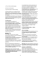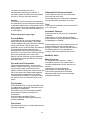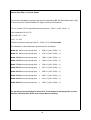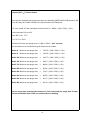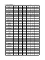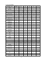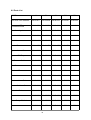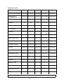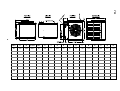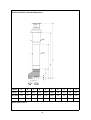
1
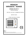
BENSON
2
VARIANTE RANGE
NATURAL GAS (G20 I2H)
PROPANE GAS (G31 I3P)
TUBULAR HEATER
INSTALLATION COMMISSI ONING
SERVICING
USER INSTRUCTIONS
BENSON
Issue 4
October 2007
33-64-695
THIS MANUAL SHOULD BE LEFT WITH THE END USER .
TO ENSURE SERVICE AND MAINTENANCE INFORMATION IS AVAILABLE ON SITE
1
Section
Contents
Page No
1.0
Compliance Notices
4
1.1
Certificates of Conformity
5
1.2
General product Information
5
1.3
General Requirements
6
1.4
Delivery & Pre-installation Checks
6
1.5
Warranty
7
Special risk areas
7
2.0
Installation
8
2.1
Installation Clearances and Mounting Heights
8
2.2
Heater Mounting
9
2.3
Warm Air Circulation
10
2.4
Air Supply
10
2.5
Flue Installation
14
2.6
Electrical Installation
22
2.7
Gas Installation
23
3.0
Commissioning
24
3.1
Electrical Pre tests
24
3.2
Gas pre tests
24
3.3
Ignition Sequence
24
3.4
Hand Over
26
4.0
Servicing
26
4.1
Servicing Procedure
26
5.0
Fault Diagnosis
28
6.0
Wiring Diagrams
30
7.0
Technical Data
39
7.1
Technical Data Common Information
39
Pre Purge information
40
7.2
Technical Data Heater Specifications
42
8.0
Parts Listing
44
9.0
Dimensions
46
2
IMPORTANT NOTICE TO INSTALLERS
Installers should satisfy themselves that the gas pipework installation is carried
out in accordance with all current legislation, Codes of Practice and
recommendations .
Additionally it may be necessary to protect the gas valves which form part of
the heater or burner assembly from potential pipe contamination particularly,
but not exclusively , where copper gas pipework is used.
In instances where copper pipework is to be used for all or part of a gas
pipework installation, including short length final connections then we advise
that installers consult with gas supplier or provider and satisfy themselves what
additional precautions may be necessary
Any reference made to Laws, Standards, Directives , Codes of Practice or other
recommendations governing the application and installation of heating appliances and
which may be referred to in Brochures, Specifications, Quotations, and Installation,
Operation and Maintenance manuals is done so for information and guidance
purposes only and should only be considered valid at the time of the publication.
Benson Heating cannot be held responsible from any matters arising from the revision
to or introduction of new Laws, Standards, Directives, Codes of Practice or other
recommendations.
3
1.0 Compliance notices
The Benson Variante range of warm air
heaters detailed herewith are manufactured
by Benson Heating within a strictly controlled
environment within the parameters of
ISO9001: 2000
These instructions are only valid if the
following country code is on the appliance
GB. IE. If this code is not present on the
appliance, it is necessary to refer to the
technical instructions which will provide the
necessary information concerning the
modification of then appliance to the
conditions of use for the country.
The Benson Variante Range has been
independently tested and assessed, and has
been found to meet the Essential
Requirements of the following European
Directives.
Gas Appliance Directive (90 / 396 / EEC)
Machinery Directive (89 / 392 EEC)
Low Voltage Directive (73 / 23 / EEC & 93 /
68 / EEC)
Electromagnetic Compatibility Directive (98 /
336 / EEC & 91 / 31 / EEC)
Product Liability Directive 65 / 374 / EEC)
Where proprietary items are incorporated
into Benson Heating products, detailed
information and instructions are also
provided as part of the information pack.
It is the responsibility of the installer, owner,
user, or hirer, of such products supplied by
Benson Heating, to ensure that they are
familiar with the appropriate information
manuals, supplied by the manufacturer, and
that they are suitably aware of the purpose of
the manuals and the safety instructions. In
addition, operators must be suitably trained
in the use of the appliance so as to ensure its
continued safe and efficient use.
Benson Heating has a commitment to
continuous improvement, and therefore
reserves the right to amend or change the
specification of the Variante Heater range
subject to agreement from The Notified
Body.
Contained within the text of the manual, the
words 'Caution' and 'Warning' are used to
highlight certain points.
Caution is used when failure to follow or
implement the instruction (s) can lead to
The manufacturer has taken reasonable and premature failure or damage to the heater or
its component parts.
practical steps to ensure that Benson
Variante Range of Heaters are safe and
Warning is used when failure to heed or
without risk when properly used. These
heaters should therefore only be used in the implement the instruction (s) can lead to not
only component damage, but also to a
manner and purpose for which they were
hazardous situation being created where
intended, and in accordance with the
there is a risk of personal injury.
recommendations detailed herewith.
The heaters have been designed,
manufactured, assembled, inspected, and
tested, with safety and quality in mind, there
are certain basic precautions which the
installer and user should be aware of, and
they are strongly advised to read the
appropriate sections of the information pack
accompanying the heater, prior to installation
or use.
The Benson Variante range of heaters
conform to the following European
Harmonised Standards.
Benson Heating supports all new products
being supplied to their customers with a
comprehensive information pack; this clearly
defines mandatory instructions for the safe
installation, use, and maintenance, of the
Appliance (s).
BS EN - ISO 12100-1:2003 &
BS EN - ISO 12100-2:2003
Safety of Machinery - Basic Concepts,
General Principles for Design
Part 1 & Part 2
4
BS EN 1020 Requirements for non domestic
gas fired forced convection air heaters for
space heating incorporating a fan to assist
transportation of combustion air and/ or
combustion products.
BS EN 60204 - Part 1 : 1993
Safety of Machinery - Electrical Equipment
for Machines Specification for General
Requirements
BS EN 60335 - Part 1 : 1988
Safety of Household and Similar Electrical
Appliances General Requirements
BS EN 55014 - 1993
Limits and methods of measurement of radio
disturbance characteristics of electrical
motor-operated and thermal appliances for
household and similar purposes, electrical
tools and similar electric apparatus
BS EN 50165 - 1997
Electrical Equipment of non-electric heating
appliances for household and similar
purposes, safety requirements
Variante heaters have been approved for
alternative flue discharge arrangements
These are detailed in following page’s
Cabinet
Manufactured from electro-zinc coated steel,
finished in a durable stove enamelled
polyester powder paint.
Heat Exchanger
Manufactured from aluminised dimpled steel
tube formed into a W shape to give
enhanced efficiency .
Flue / Combustion Air Spigot
Each heater is fitted with two spigots both of
which are located to the rear of the appliance
One of the pair is for connection for the flue
whilst the other is a screened combustion air
intake
WARNING
(SEE FLUE INSTALLATION 2.5 PAGE 14)
The Benson Variante range of gas unit
heaters meet with the governments criteria in
Burner
respect of the Enhanced Capital Allowance
The induced draught multi in-shot burner
Scheme
assembly is manufactured from aluzinc
coated steel and mounted to a common steel
1.1 Certificates of conformity
manifold which can be easily withdrawn
through the burner access compartment.
Declarations and Certificates are available
upon request from the Quality Control
Burner Control
Department at Benson Heating .
Notified Body PIN Reference is
The heaters are fitted with automatic ignition
063BQ5461
for all models within the range.
1.2 General product information
Exhaust Fan
The Benson Variante range includes for 10
model sizes with outputs from 12.0 kW to
144.0 kW,
Each model can be configured for use as
axial fan crossflow (VRA) centrifugal fan
(VRC) and axial fan downflow (VRE)
Combustion gases are evacuated to
atmosphere via an in built power flue venter
fan which is safety interlocked to the gas
valve via an air pressure proving device
Air Movement Fan
VRA / E) are supplied with an Axial fan for
Variante heaters are suitable for operation on free blowing applications .
natural gas (G20) or LPG (Propane (G31)
Variante (C) are supplied with Centrifugal
fans suitable for ducted applications Note
The Model Range is made up as follows
Neither asbestos nor soft soldered joints are
used in the construction or manufacture of
Model No
40
70
100
135
170 the Benson VRA/C/E range of Heaters.
The materials selected for use can
12 19.6 29.4 39.2 49.0 withstand the mechanical, chemical, and
Output kW
thermal stresses which they will be subject to
Model No
200 250 330
410
490 during foreseen normal use when installed in
accordance with the manufacturers
58.8 72.0 96.0 120.0 144.0
Output kW
recommendations.
5
e) The position of the heater relative to the
supply of fresh air
1.3 General Requirements
Caution
Before installation, check that the local
distribution conditions, nature of gas and
pressure, and the current state adjustment of
the appliance are compatible.
Warning
Unauthorised modifications to the appliance,
or departure from the manufacturers
guidance on intended use, or, installation
contrary to the manufacturers
recommendations may constitute a hazard.
f) The position of the heater relative to
potential stratification / circulation problems,
which generally occur at higher levels and
which may be overcome through the
provision of a suitable de-stratification unit.
g) The position of the heater relative to
service and maintenance requirements
Caution
The heater must not be installed within an
area where the conditions are unsuitable,
e.g. where the atmosphere is highly
Note
To ignore the warning and caution notices, corrosive, has a high degree of salinity, or
where high wind velocities may affect burner
and to ignore the advice from the
manufacturer on installation, commissioning, operation. Suitable protection should be
provided for the appliance when it is located
servicing, or use, will jeopardise any
in a position where it may be susceptible to
applicable warranty, moreover, such a
situation could also compromise the safe and external mechanical damage from; for
example, fork lift trucks, overhead cranes
efficient running of the appliance itself, and
etc.
thereby constitute a hazard.
This appliance must be installed by a
competent person and in accordance with
European, National, and Local criteria,
including any relevant standards, codes of
practice the requirements of the current
building Regulations (and in particular parts
J & L), Health and safety regulations IEE
regulations and any requirements of the local
Authority, Fire Officer or insurers
Relevant standards may include BS6230,
BS6891 and BS5588 parts 2 and 3
1.4 Delivery and pre-installation
checks
The heater is supplied wrapped in heavy
duty protective polythene, mounted on a
pallet.
On receipt of the heater, the following
checks should be carried out;
a) The model is as per order
b) That it is undamaged
Prior to installation the following points
should be considered;
c) That it is suitable for the gas supply and
pressure
a) The position of the heater for the optimum
efficient distribution and circulation of warm d) That it is suitable for the electrical supply
air
If any of these points are not satisfied then
b) The position of the heater relative to the
contact should be made with the Sales Office
route of the flue
at Benson Heating as soon as possible by
telephoning 01547-528534. In the case of
c) The position of the heater relative to the
claims for damage, this must be reported in
supply of gas
writing within 24 hours of delivery, in order to
comply with insurance criteria
d) The position of the heater relative to the
electrical services, wiring routes, and if
appropriate, any additional controls.
6
1.5 Warranty
The heater is supplied with a 1 year parts
and labour warranty and a further year on all
parts excluding consumable’ s.
In addition to this there is also a 10 year
time related warranty on the combustion
chamber.
The warranty commences from the date of
dispatch from the manufacturer, and is
subject to the terms detailed within the
Benson Heating 'conditions of business'.
following information to enable processing to
take place;
(1) Heater model
(2) Heater serial number
(3) Order reference/date of order, together
with full installation details (name and
address)
(4) Details or symptoms of fault
(5) Installers name and address.
Faulty parts must be returned to the Benson
Heating Spares Department, the address of
which is provided on the cover of this
Note (i)
manual. Any such parts will undergo
The warranty may be invalidated if a) The warranty registration/commissioning inspection to verify the claim. Replacement
card has not been completed and returned to parts supplied prior to this may be charged,
and a credit supplied upon subsequent
Benson Heating
validation of the warranty claim.
b) The installation is not in accordance with Consumable items are specifically not
included within the scope of the warranty.
the general requirements of this manual
c) The flue arrangement and air supply for
the heater are not in accordance with the
manufacturers recommendations, codes of
practice, or similar standards
Note (iii)
Notification is required immediately a fault is
suspected.
The manufacturer will not accept
responsibility for any additional damage that
has been caused, expense incurred, or
d) Air flow through the heater is not in
accordance with the manufacturers technical consequential loss resulting from any failure
of the heater(s).
specifications
SPECIAL RISK AREAS
Where it is proposed to install a heater
within a special risk area (e.g. an area
containing flammable vapours where petrol
engined vehicles are stored parked or
f) The main electrical supply input to the
serviced where paint spraying occurs, or
heater has been interrupted during the
where woodworking machinery or other
heating mode
flammable dust creating process’s are
employed then restrictions, additional
g) The heater has been subject to and
affected by the ingress of water in any form regulations concerning the heater flue wiring
or controls may apply.
h) The heater is not operated at the rating(s) It is strongly recommended that you contact
Benson Technical before installation
laid down in the manufacturers technical
Caution
specifications
When used in room sealed mode it may be
i) The heater has not been operated or used possible to install Variante heaters in areas
containing flammable vapours, high levels of
within the normal scope of its intended
airborne dust combustible dust chlorinated or
application
halogenated hydrocarbons degreasing
solvents styrenes other laminating materials
j) The manufacturer's recommended
or airborne silicones. Benson Technical
minimum service requirements have not
should be contacted before installation .
been complied with
Failure to do so may invalidate or reduce
Note (ii)
guarantee cover.
All warranty claims must contain the
e) Internal wiring on the heater has been
tampered with or unauthorised service
repairs undertaken
7
Plant Room Siting
Provided certain criteria are met it is possible
to install VRC (centrifugal fans) within a plant
room heaters installed in plant rooms should
only be configured for use in room sealed
mode and provision should be made for the
positive connection of flues , combustion air
pipes, warm air discharge and return
ductwork where such a siting is a
requirement it is recommended that you
consult Benson Technical prior to installation
Additionally the maximum temperature within
the plant room should not exceed 320C
2.0 Installation
The location chosen for the heater must
allow for the fitting of an effective flue
system.
The location must also allow for adequate
clearance for the air supply, return air
circulation, gas supply, electrical supply,
whilst also providing good and safe working
access.
The heater must be installed so that it is
level, supports for the heater must be
sufficiently robust to withstand the weight of
the heater and any ancillary equipment
Any combustible material adjacent to the
heater or flue system must be so placed or
shielded so that its surface temperature does
not exceed 650C. Generally a free blowing
heater should be located at a height
(measured from floor level to the base of
unit) as detailed within section 2.1
VRA free blowing heaters are at their most
effective when located as close to the
working area as possible. However care
should be exercised to avoid directing the
discharged air directly onto the occupants of
the area to be heated.
Where the passage of cold air causes
problems (e.g. by entrances, loading bays
etc) it is considered favourable if the heater
is positioned so as the discharge towards or
across the cold air source from a distance
from 1.5m - 6m dependent upon the size of
the entrance and the air throw characteristics
of the heater. On exposed walls heaters
should be positioned so as to discharge
towards, or along the length of the exposed
wall.
8
In areas where it is proposed that more than
one heater is to be installed, a general
scheme of circulation should be drawn up
and maintained, thereby offering the best
heat distribution. Air pressure within the area
heated and the outside air pressure must
remain the same, factors influencing this
would be the presence of extraction systems,
ventilation systems, and various types of
process plant.
VRA heaters are only suitable for free
blowing applications or where the duct length
does not exceed 2 metres.
In which case the cross- section of the duct
must be at least the same as that of the
heater discharge grille
VRE heaters configured for down flow
applications should be suspended centrally
over the area into which the warm air is to be
discharged .
2.1 Installation Mounting Heights and
Clearances
The Heater must be installed within the
mounting heights indicated below
The following heights in metres
Model
VRA/C
40
70
100
135
170
Min
1.8
1.8
2.0
2.0
2.4
Max
2.3
2.3
2.5
2.5
3.0
Model
VRA/C
200
250
330
410
490
Min
2.4
2.4
2.4
2.4
2.4
Max
3.0
3.5
3.5
3.5
3.5
Model
VRE
40
70
100
135
170
Min
3.5
4.0
4.0
4.0
5.0
Max
4.5
5.5
6.0
7.0
8.0
Model
VRE
200
250
330
410
490
Min
5.0
5.0
6.0
6.0
6.0
Max
12.0
8.0
10.0
12.0
12.0
Clearances VRA in mm
Model
40
70
100
135
170
200
250
330
410
490
Above
300
300
300
300
300
300
300
300
300
300
Below
300
300
300
300
300
300
300
300
300
300
Right side
250
250
250
250
250
250
250
250
250
250
Left side
800
800
800
800
800
800
950
950
950
950
Rear
300
350
400
500
500
560
560
560
560
630
Clearances VRC in mm
Model
40
70
100
135
170
200
250
330
410
490
Above
300
300
300
300
300
300
300
300
300
300
Below
300
300
300
300
300
300
300
300
300
300
Right side
250
250
250
250
250
250
250
250
250
250
Left side
800
800
800
800
800
800
950
950
950
950
Rear
200
200
200
200
200
200
200
200
200
200
Clearances VRE in mm
Model
40
70
100
135
170
200
250
330
410
490
Above
1500
1500
1500
1500
1500
1500
1500
1500
1500
1500
Below
4000
4000
4000
4000
5000
5000
6000
6000
6000
6000
Right side
250
250
250
250
250
250
250
250
250
250
Left side
800
800
800
800
800
800
950
950
950
950
Rear
250
250
250
250
250
250
250
250
250
250
Left hand side = burner compartment side
b) VRA heaters can be mounted on
specifically designed cantilever wall or
vertical stanchion brackets which locate
The heater and flue must be adequately
supported by one of the following methods ; directly to the four M10 fixings on the heater
casing.
Alternatively VRA or VRC units can be
a) Suspension by steel drop rods or straps
from the M10 fixing points located on top of mounted on cantilever type wall brackets
however consideration must be given to
the heater
These must be of sufficient strength to safely ensure that the bracket is large enough to
support the heater whilst providing the
carry the weight of the unit and ancillary
necessary clearances
equipment. The straps may only drop
vertically to eyebolts, if used; I.E. They must In either case the installer should ensure that
not be joined to the eyebolt at an angle to the the wall wall fixings or other support medium
vertical, and eyebolts if used should be of an is capable of supporting the weight
approved type.
2.2 Heater Mounting
9
c) On a level non-combustible surface
capable of adequately supporting the weight
of the unit and ancillary equipment .
OR
•
If the design air change rate of the
heated space is 0.5 air changes per
hour or greater
The
design
air change rate may be satisfied
2.3 Warm Air Circulation
by natural infiltration or by mechanical
The air heater should be positioned to enable ventilation.
maximum circulation of discharged warm air
Combustion air ventilation
within the area to be heated, whilst taking
will be required if
account of personnel within the area,
sources of cold air ingress , and obstructions.
•
The heater(s) are installed with flue
only (ie without the positive connection
Ensure louvres are adjusted outwards
to atmosphere of a combustion airduct)
and ensure blades are not resonating
And
The design air change rate of the
The air temperature rise on passing the heat •
heated space is less than 0.5 air
exchanger is typically around 340 C
changes per hour
A full and unobstructed return air path to the
air heater must be provided
Where heater(s) are installed without the
(see 2.4 Air Supply).
positive connection of combustion ductwork
within a heated space where air change rate
Where the heater is positioned to deliver
blown air through an opening in a wall, return of that heated space is less than 0.5 air
changes per hour then it will be necessary to
air intakes should be located so that they
provide either natural ventilation openings to
cannot become blocked. Similarly these
intakes must be positioned so as not to draw the heated space (Section 2.4.1.1 refers)
or the mechanical ventilation of the heated
in odours, fumes, hazardous vapours or
space (Section 2.4.1.2 refers)
particles.
2.4 Air Supply for Combustion and
Ventilation
2.4.1.1
Natural Ventilation Openings to the
Heated Space
Consideration must be given to the provision
of air for the purposes of combustion and
ventilation of the heated space, plant room or
enclosure where the heaters are to be
installed .
It is strongly recommended that BS 6230 :
2005 is referred to for further information
concerning ventilation requirements
If the heater(s) are to be installed without the
positive connection of combustion air
ductwork within a heated space, and where
the design air change rate of that heated
space is less than 0.5 air changes per hour,
then provision for low level natural ventilation
openings only will be necessary.
The minimum free area of the low level
natural ventilation opening shall be
2.4.1 Heaters installed within the
heated space
•
2 cm2 for each kW of rated heat input
Where heaters are installed within the heated
space (i.e. not a plant room , or enclosure ) The low level natural ventilation opening
should be situated on an external wall and be
then
within 1000 mm of floor level for natural gas
Combustion air or heater related ventilation and ideally at floor level for lpg gas
installations but in any event no higher than
air will not be required if 250 mm.
•
The heaters are installed in room
sealed mode (ie with a positive
connection to atmosphere of both flue
and combustion air)
10
The table below provides specific data for
each heater model as Minimum Free Area Of
Ventilation Opening
MODEL
High Level
Low Level
cm2
cm2
40
None
26
70
None
43
100
None
64
135
None
86
170
None
107
200
None
128
250
None
158
330
None
211
410
None
263
490
None
315
2.4.2 Heaters Installed within a Plant
Room or Enclosure
A plant room means a room housing the
heater plant and probably other items of
building service plant and would generally
have generous space for maintenance
An enclosure is where the heater is installed
within a compartment or confined area where
space is limited
Where heaters are installed within a plant
room or enclosure then provision for both
combustion air and / or air for general
ventilation will be required by means of high
and low level ventilation openings (sections
2.4.2.1 and 2.4.2.2 refer to plant room
applications and sections 2.4.2.3 and 2.4.2.4
refer to enclosure applications).
Alternatively the plant room or enclosure may
be mechanically ventilated (section 2.4.2.5
refers)
2.4.1.2 Mechanical Ventilation to the
Heated Space
In the event that the heater(s) are to be
installed without the positive connection of
combustion ductwork within a heated space
and where that heated space has a design
air change of less than 0.5 air changes per
hour and that the installer prefers to
mechanically ventilate the heated space
rather than provide ventilation openings
then -
2.4.2.1 Natural Ventilation Openings to
Plant Rooms for Room Sealed Heaters
For plant room applications the minimum free
area of ventilation opening will depend upon
whether the heater(s) is installed in room
sealed mode (ie with a positive connection to
atmosphere of both flue and combustion air)
Or with flue only (ie without the positive
connection to atmosphere of a combustion
air duct)
Where the heater(s) is installed in a plant
room and in room sealed mode (ie with a
positive connection to atmosphere of both
flue and combustion air ) the minimum free
area of ventilation opening needs to be
•
The heated space needs to be
mechanically ventilated so that the
design air change is 0.5 air changes
per hour or greater.
•
It is a requirement that the mechanical •
ventilation shall be of the ! Input ! Type
with either natural or mechanical
extraction
•
•
•
Systems of mechanical extraction with
a natural inlet shall not be used
At high level 5 cm2 for each kW of
rated heat input
At low level 5 cm2 for each kW of rated
heat input
The high level ventilation opening should be
sited on an external wall and positioned as
It is necessary to provide an automatic high as is practical and always within the top
means to safely inhibit heater(s)
15% of the wall height
operation should mechanical air supply
fail for any reason
11
The low level natural ventilation opening
should be situated on an external wall and be
within 1000 mm of floor level for natural gas
and ideally at floor level for l.p.g gas
installations but in any event no higher than
250 mm.
should be situated on an external wall and be
within 1000 mm of floor level for natural gas
and ideally at floor level for l.p.g gas
installations but in any event no higher than
250 mm.
2.4.2.3 Natural Ventilation Openings to
2.4.2.2 Natural Ventilation Openings to Enclosures for Room Sealed Heaters
Plant Rooms for Flued Heaters
The table below provides specific data for
each heater model as The table below provides specific data for
each heater model as -
Minimum Free Area Of
Ventilation Opening
Minimum Free Area Of
Ventilation Opening
MODEL
High Level
cm
2
Low Level
cm2
High Level
Low Level
cm2
cm2
40
26
52
40
65
65
70
43
85
70
106
106
100
64
128
100
160
160
135
86
171
135
213
213
170
107
214
170
267
267
200
128
256
200
320
320
250
158
316
250
394
394
330
211
422
330
527
527
410
263
525
410
656
656
490
315
630
490
787
787
Where the heater(s) is installed in a plant
room and in flue mode (ie without a positive
connection to atmosphere of combustion air
ductwork ) the minimum free area of
ventilation opening needs to be
•
MODEL
At high level 2 cm2 for each kW of
rated heat input
For enclosure applications the minimum free
area of ventilation opening will also depend
upon whether the heater(s) is installed in
room sealed mode (ie with a positive
connection to atmosphere of both flue and
combustion air)
Or with flue only (ie without the positive
connection to atmosphere of a combustion
air duct)
Where the heater(s) is installed in a plant
At low level 4 cm2 for each kW of rated room and in room sealed mode (ie with a
heat input
positive connection to atmosphere of both
flue and combustion air ) the minimum free
The high level ventilation opening should be area of ventilation opening needs to be
sited on an external wall and positioned as
high as is practical and always within the top •
At high level 5 cm2 for each kW of
15% of the wall height
rated heat input
•
•
The low level natural ventilation opening
12
At low level 5 cm2 for each kW of rated
heat input
The high level ventilation opening should be
sited on an external wall and positioned as
high as is practical and always within the top
15% of the wall height
The low level natural ventilation opening
should be situated on an external wall and be
within 1000 mm of floor level for natural gas
and ideally at floor level for l.p.g gas
installations but in any event no higher than
250 mm.
2.4.2.5 Mechanical Ventilation to a
Plant Room or Enclosure
2.4.2.4 Natural Ventilation Openings to The table below provides specific data for
Enclosures for Flued Heaters
each heater model as The table below provides specific data for
each heater model as -
Minimum Free Area Of
Ventilation Opening
MODEL
Minimum Free Area Of
Ventilation Opening
MODEL
High Level
cm
2
Low Level
cm2
High Level
Low Level
40
65
130
cm2
cm2
70
106
212
40
65
65
100
160
320
70
106
106
135
213
426
100
160
160
170
267
533
135
213
213
200
320
640
170
267
267
250
394
788
200
320
320
330
527
1053
250
394
394
410
656
1312
330
527
527
490
787
1574
410
656
656
490
787
787
In the event that the installer prefers to
mechanically ventilate the plant room or
enclosure rather than provide ventilation
openings then -
Where the heater(s) is in an enclosure and in
flue only mode (ie without a positive
•
connection to atmosphere of combustion air
ductwork ) the minimum free area of
ventilation opening needs to be
•
At high level 5 cm2 for each kW of
rated heat input
•
At low level 10 cm2 for each kW of
rated heat input
•
The high level ventilation opening should be
13
The plant room or enclosure needs to
be mechanically ventilated at the rate
of 4.14 m3/h of fresh air per kW or
rated heat input.
It is a requirement that the mechanical
ventilation shall be of the ’input’ type
with either natural or mechanical
extraction. Where mechanical
extraction is selected then the
extraction rate should be 5%-10% less
than the input rate.
•
Systems of mechanical extraction with
a natural inlet shall not be used
WARNING
On VRA/C 200 to 490 a Combustion Air
Plate is supplied as standard this MUST
•
It is necessary to provide an automatic be fitted in place of the combustion air
means to safely inhibit heater(s)
spigot if the heater is to be installed in the
operation should mechanical air supply flue only option
fail for any reason
The flue assembly must comply with all the
The table below provides specific data for
relevant regulations regarding height and
each heater model as materials, and must terminate with an
approved flue terminal.
Care should be taken to ensure that the flue
Mechanical Ventilation terminal is not situated in a high pressure
MODEL
Rate for Plant Room or area, the proximity of buildings and other
obstacles which will influence this must be
Enclosure
taken into account, preferably at the design
M3/h
stage.
54
40
All Variante Heaters are equipped with a built
in flue venter fan which prevents the
88
70
re circulation of combustion products,
133
consequently an external draught diverter,
100
barometric damper, or anti spillage system
177
135
must not be installed. Such devices are
unnecessary on the BVA/C range of heaters.
221
170
200
265
250
327
330
436
410
543
490
652
Horizontal flue installations must not
exceed the following
VRA/C 040
3 Metres overall length.
VRA/C 070/200 6 Metres overall length.
VRA/C 250/490 8 Metres in overall length.
2.5 Flue Installation.
An integral flue spigot is fitted to all Variante
Air Heaters thereby allowing the flue to
connect directly to the heater.
The design of the flue must ensure that it can
be disconnected to allow for cleaning and
servicing.
All joints should be sealed between the
sections.
Warning
It is essential that the products of combustion
are flued to the outside of the building.
Each heater must have its own separate flue,
with a flue diameter of not less than is
detailed in section 7.2 within this manual.
14
Each 900 bend corresponds to 1Mtr of flue
length
Each 450 bend corresponds to 0.8 Mtr of flue
length
Flue pipe should be supported at intervals
not exceeding 1.8 mtrs
In order to provide adequate natural draught,
the minimum length of horizontal flue must
not be less than 1Mtr.
For vertical flue installations the flue should
rise vertically where possible bends should
not exceed 450 and the number of bends
should be kept to a minimum.
Maximum vertical flue length must not
exceed 10 Metres
The temperature of the combustion products
can be as high as 1700 C and therefore tend
to rise naturally within the flue. Unnecessary
bends and restrictions should therefore be
avoided.
Provision for the disconnection of the flue for
servicing and inspection purposes must also
be made.
The position of the flue and its terminal
should be such that it does not impair the
combustion process. It should terminate in
an exposed position so as to allow the free
escape of flue gases without risk of their reentering the building through windows,
ventilation ports etc.
The following distances in mm’s should
be observed
200 below guttering or eaves
300 from corners or openings (windows
doors etc) and from other horizontal
terminals on same wall
1200 from a facing surface
1500 from another terminal vertically on the
same wall
2000 from ground level
The heaters must be connected to the flue
system supplied by Benson Heating and be
capable of withstanding the stresses and
loadings associated with normal use.
When designing the flue system the
prevention of the formation and entrapment
of condensation must be a key consideration.
Horizontal flue should be fitted ensuring a
slight gradient approx 20 towards the terminal
Where condensation is unavoidable traps
should be included to encourage the
condensates to flow freely to a point from
which they may be released, preferably into
a gully.
The condensate pipe from the flue to the
disposal point must be made from corrosion
resistant pipe of not less than 25mm internal
diameter.
If the flue passes through a wall, ceiling, or
roof made from combustible material then it
has to be sleeved so as to provide a
minimum of a 25mm void between the
exterior of the flue and the internal wall of the
sleeve.
15
C32 Vertical Co axial flue Kit options
L1 maximum flue length 10 metres
Kit comprises
Item (1) Co-axial flue terminal Ø 80 x Ø 80
Item (3) 900 by Ø 80 bend x 2
Part No
33-55-010
33-54-005
Extra pipes to extend the flue are available as an option
Pipe
Pipe
Pipe
Bend
Ø
Ø
Ø
Ø
80 x 1000 mm
80 x 250 mm
80 x 500 mm
80 x 450
16
33-54-001
33-54-002
33-54-003
33-54-004
C32 Vertical Co axial flue Kit options
L1 maximum flue length 10 metres
Part No
Kit comprises
Item (1) Co-axial flue terminal
Item (2) Ø100 x 250 mm pipe
Item (3) 900 by Ø100 bend x 1
Item (4) 450 by Ø100 bend x 2
33-55-107
33-54-103
33-54-105
33-54-104
Extra pipes to extend the flue are available as an option
Pipe Ø 100 x 1000 mm
Pipe Ø 100 x 500 mm
Pipe Ø 100 x 250 mm
17
33-54-101
33-54-102
33-54-103
C32 Vertical Co axial flue Kit options
L1 maximum flue length 10 metres
Part No
Kit comprises
Item (1) Co-axial flue terminal
Item (2) Ø130 x 250 mm pipe x 2
Item (3) 900 by Ø130 bend x 2
33-55-207
33-54-203
33-54-205
Extra pipes to extend the flue are available as an option
Pipe Ø 130 x 1000 mm
Pipe Ø 130 x 500 mm
Pipe Ø 130 x 250 mm
Bend Ø 130 x 450
18
33-54-201
33-54-202
33-54-203
33-54-204
Option B22
In this configuration the heater is connected to a single flue pipe to discharge the products
of combustion outside the building either through the roof or through a wall. The air for
combustion is taken from inside the building.
Heater
Unit
Flue Exit
HORIZONTAL
Flue Exit
VERTICAL
MIN.
MAX.
MIN.
MAX.
40
m
1,00
3,00
1,00
5,00
70
m
1,00
6,00
1,00
10,00
100
m
1,00
6,00
1,00
10,00
135
m
1,00
6,00
1,00
10,00
170
m
1,00
6,00
1,00
10,00
200
m
1,00
6,00
1,00
10,00
250
m
1,00
8,00
1,00
10,00
330
m
1,00
8,00
1,00
10,00
410
m
1,00
8,00
1,00
10,00
490
m
1,00
8,00
1,00
10,00
19
Option C12
In this configuration the heater is connected to a horizontal flue system discharging the
products of combustion and bringing in the combustion air from outside the building in which
the heater is located.
The outlet / inlet must be through the wall and may be made with two separate pipes or with
a horizontal coaxial concentric terminal
Heater
Unit
Horizontal
L1 MIN
Concentric Flue
L1MAX.
40
m
0.50
3.00
70
m
0.50
6.00
100
m
0.60
6.00
135
m
0.70
6.00
170
m
0.85
6.00
200
m
1,0
6.00
250
m
0.7
8.00
330
m
0.85
8.00
410
m
1,05
8.00
490
m
1,20
8.00
20
VRE Flueing options B22 Single pipe flue only and C32 Vertical coaxial
Heater
Unit
Flue Exit
VERTICAL
CO/AXIAL
Flue Exit
VERTICAL
MIN.
MAX.
MIN.
MAX.
40
m
1,00
3.00
1,00
5,00
70
m
1,00
6,00
1,00
10,00
100
m
1,00
6,00
1,00
10,00
135
m
1,00
6,00
1,00
10,00
170
m
1,00
6,00
1,00
10,00
200
m
1,00
6,00
1,00
10,00
250
m
1,00
8,00
1,00
10,00
330
m
1,00
8,00
1,00
10,00
410
m
1,00
8,00
1,00
10,00
490
m
1,00
8,00
1,00
10,00
21
Caution
It is imperative that the flue should be
properly sealed where it passes through the
roof, this can best be achieved by using the
approved method of roof flashing plate and
cravat. The flue spigot outlet on all Variante
heaters is in horizontal configuration.
Note
It should be noted that claims made under
warranty and attributed to the ingress of
water may not be considered especially if an
approved method of sealing has not been
used, or if the design of the flue has not
made provision for possible condensation
problems.
It is also recommended that BS5854: 1980
and BS5440: parts 1 and 2 are used as a
consultative document when considering flue
requirements.
If terminating through a wall only use Benson
approved horizontal terminals
2.6 Electrical Installation
the incorrect use of the heater
Each heater requires a permanent 230V
50Hz 1ph / 415v/3ph/50Hz electrical supply,
which must be wired through a fused isolator
fitted with a fuse of the correct rating (see
section 7.1). The correct supply connection
points for the live, neutral, and earth.
Wiring diagrams are also detailed within this
manual, (section 6.0 )
The electrical supply isolator should be
mounted adjacent to the air heater in an
easily accessible position to allow for
servicing isolation, or emergency shut off.
Electrical panel
Warning
Ensure that the mains isolator is turned OFF
before undertaking any electrical work on the
heater. Access to the electrical panel is
gained by opening the right hand heater side
panel.
All electrical wiring and connections must be
Warning
in accordance with the relevant European,
National, and Local regulations as well as to Ensure that all connections are secure and
that there are no loose strands which could
IEE Standards.
bridge across the terminals.
Ensure that the Electric and Gas supplies are A minimum conductor size of 1.0 mm
(diameter) is required.
turned off before any electrical work is
carried out on the heater.
Also ensure that wiring cannot make contact Caution
with any metal surfaces liable to be subject
to high temperatures, and where insulation of When using CP4 Optimised Controller
Consideration should be made when routing
the wiring could be impaired as a result of
the cable between the control and heater.
such contact.
Avoiding where possible any existing cables
All Variante models must be earthed.
and switch gear as any induced voltage may
affect the operation of the sequential control
Warning
box within the heater.
Ensure that the electrical supply is
compatible to the heater.
ALL HEATERS ARE NEUTRALLY RESET It is recommended that screened cable is
used when the control is to be sited more
than 10 metres away from the heater
Caution
The main electrical supply must not be
switched off or disconnected as a method for One electrical panel per heater is required,
stopping the heater, the exception to this is in unless heaters are specified for multiple
heater control applications. On no account
the event of an emergency, or when the
should more than one heater be connected
heater has been allowed to cool sufficiently
to prevent any damage from being sustained to a single time switch or thermostat.
to the heater or its controls (ie: during
The only exception to this is when a control
servicing).
panel suitable for multiple heater applications
Claims for damage will not be considered if
is supplied by the manufacturer.
they have resulted from incorrect wiring or
22
Any ancillary electrical items e.g. room
thermostats , time switches, remote panels
etc, must be wired into the heater electrical
circuit in accordance with the diagrams
provided
Note
When external controls operate to switch
the heater OFF, power to the heater should
remain to allow the fan to continue to operate
to sufficiently cool the heater thereby
preventing damage to the heat exchanger.
2.7 Gas installation
Warning
Please read notice on page 3 of this
manual
As there have been recorded instances of
the deposition of copper sulphide dust within
the valves and orifices of gas appliances as
a direct result of a reaction between the
hydrogen sulphide contained in some natural
gasses and copper pipe we recommend that
Fan limit control
the heater(s) should not be connected to any
( Situated inside the right hand side panel)
natural gas pipe distribution system which
utilizes copper pipework, including final
FAN ON 50c
FAN OFF 30c
These settings may require slight adjustment connections. Instead steel pipework should
be used throughout.
on commissioning
In the event that it is impractical to use steel
Fan control (white button)
pipework or where installers are obliged or
The fan control switch features normally
open 230V contacts, and is wired to control insist on using elements of copper pipework
within the installation then we strongly
the live supply to the fan motor . When the
recommend that the gas supplier be
circuit is made, the fan will switch on when
the heat anticipator has closed the fan switch consulted as specific conditions and
contacts. When the thermostat or time switch requirements may be necessary.
shuts down the burner, the fan will continue
The Variante range of heaters are all
to run until the thermal switch has cooled
sufficiently to prevent the residual heat from manufactured and pre set for use with
damaging the heater or its controls.
Natural Gas, and all feature 1/2” or 3/4” BSP
On start up the fan delay prevents air being connection points. Prior to installation the
circulated until the desired temperature is
supply characteristics (gas type and
achieved
pressure) must be checked to ensure that
they are in accordance with the data plate on
c
the heater.
Limit control (red button) SET at 100
An adjustable high temperature manual reset The gas supplier should check that the meter
limit control. If this control needs resetting the and service connection to the heater are
cause should be determined and rectified
capable of delivering the required volume of
immediately.
gas, thereby ensuring that the minimum
On models with two fans a second limit
burner pressure can be achieved.
control is situated inside the right side panel Consideration should be given to the
and is wired in series. Operation of either
pressure drop on single and multi heater
switch will shut down the heater. On larger
installations and the effect they may have on
models there will be additional limit stats
other plant sharing the supply.
fitted
If it is necessary to fit a gas pressure
booster, the controls must include a low
Caution
The power supply to the fan must not be
pressure cut off switch which must be fitted
interrupted, the only time when power supply on the supply / inlet side of the booster. It is
can be disconnected or interrupted is during also a requirement that the gas supplier is
servicing or in emergencies
advised prior to the installation or fitting of
If there is a requirement for the heater to be the booster.
switched off over night then the gas valve
Each heater supply must be fitted with a
circuit should be opened via a time switch,
separate isolating cock positioned adjacent
etc, as per the wiring instructions and
to and upstream of the union which must be
diagrams supplied within section 6.0 of this
sited outside the heater.
manual.
The isolating cock should be of the 900 turn
23
type and should be clearly marked OPEN /
CLOSED it should also be installed so as to
fall to the closed position
An approved gas jointing compound must be
used on all joints and unions and the system
purged and tested for soundness prior to
final connection
The connection to the heater can be made
by way of either an approved flexible
coupling or rigid connection . Threaded
connections must comply to ISO 288/1 or
ISO 7/1 further information concerning
accepted European practice is detailed in
BS EN1020 1998.
The diameter of the pipework from the
isolating cock to the burner must not be less
than the diameter of the connection into the
multiblock.
Note
Reference to The Institute of Gas Engineers
publications Utilisation Procedures IGE/UP1
and IGE/UP2 together with reference to
BS6891 is strongly advised.
The following pre-commissioning checks
should be undertaken, having first ensured
that the gas and electrical supplies are
turned off.
(a) Check that all panels and fasteners are
secure and in place.
(b) Check that the heater is mounted safely.
(c) Check that the flue is sealed, secured,
and adequately supported.
(d) Check that the fan is free to rotate, that
the fan is secured to its shaft, and that the
guards and fan assembly are all in place and
properly secured.
(e) Check that the heater is installed so that
it is not tilted and remains square.
(f) Check that the outlet louvres (Axial
heaters) are set to offer minimum resistance
to air flow.
3.1 Electrical pre-tests
3.0 Commissioning
Note
It is a requirement that only suitably
qualified and competent personnel are
allowed to undertake the commissioning
of the heater.
It is also strongly recommended that prior
to commissioning the engineers
familiarises themselves with the heater.
the specific requirements of the
installation / application, and the
information contained within the manual.
Warning
All heaters are subject to a rigorous test
programme prior to despatch, whilst such a
programme does involve pre-commissioning
and the setting of the heater to operate
efficiently and within its designed operational
limits this does not mean that the function of
thorough on site commissioning is less
important
It is strongly recommended that the
equipment used for the sampling and
analysis of the flue gases is accurate to
within +/- 0.1% and maintained so that it is
regularly calibrated.
The electrical safety checks must include the
following
a) Test for earth continuity
b) Test for resistance to earth
c) Check live and neutral connections are
correct.
d) Check to ensure that when the external
controls operate to switch the heater off,
power remains to the fan
3.2 Gas supply pre-test
Ensure that the service pipework has been
installed purged and tested in accordance
with the relevant regulations, and that the
installation is served by an adjacent isolating
cock.
Connection from the supply to the heater
must also comply with the relevant
regulations (see section 8.0) and must have
been purged and soundness tested by an
authorised engineer
3.3 Ignition sequence
PRE START DRY RUN
In order to test that all controls are in good
24
working order, the control sequence should
first be tested with the gas supply turned Off.
Ensure gas isolating cock is in the Off
position
Warning
If during the following sequence of operations
the heater fails to operate correctly the fault
should be traced and rectified before
proceeding, if necessary referring to section
5.0 fault diagnosis.
a) Switch off the main electrical supply to the
heater
b) Turn off gas supply to the heater
c) Open side panel, and connect manometers
to the gas supply test point and to the main
burner test point
d) Ensure outlet louvres are correctly set
e) Ensure fan rotation is not impaired or
obstructed
f) Set room thermostat to its lowest setting
g) If a time switch is fitted ensure it is set to
an on period
h) Switch on electrical supply
burner will light.
The flame can be observed at the burner
manifold, check that the burner is providing a
good flame i.e. even and stable.
n) Check pressure readings on the
manometers, and continue to let the heater
fire for ten minutes
o) When the fan starts ensure that the
direction of rotation is correct , and that the
fan start is within 2 minutes of burner ignition
Caution
If the fan fails to operate within approximately
2 minutes and the heater goes to overheat it
will shut down through breaking the circuit to
the gas valve, the cause must be ascertained
and rectified before re-ignition.
Once the limit thermostat has tripped out it
must be manually reset to allow re-ignition to
take place.
p) After ten minutes check burner head
pressure is as specification - adjust as
necessary by removal of the gas pressure
adjustment cover, and using a screwdriver
turn the adjustment screw on the governor as
follows: Clockwise to increase.
Anti clockwise to decrease.
i) Use leak tester to test for soundness on the
unions and pipework
q) Check that the gas pressure remains
satisfactory for all appliances on the same
j) Operate the heater through the installed
circuit
control system.
On start the signal will activate the flue venter r) Undertake combustion tests checking CO
for a pre purge period and in turn will make
CO2 and efficiency (see section 7.0)
the air proving switch, once made, the air
CO should not exceed (20PPM)
proving switch will complete the circuit to the
control box and after a 40 second Delay the s) Check that the burners are extinguished
automatic control should attempt light the
when the thermostat is set to its lowest
burner, because the gas is turned off and
setting, and then remove the manometers.
flame cannot be established , the control box
t) Turn the thermostat to its highest setting to
will go to LOCKOUT.
re light the burner and replace the adjustment
k) Reset the control on completion of dry run. screw cover
On completion mark the gas valve
l) Open gas cock
adjustment screw with paint/sealant to
prevent tampering with valve
m) Operate heater through installed control
The flue venter will pre purge the heater and u) Turn the thermostat to its lowest setting
in turn operate an air proving switch which
and shut off the gas supply at the gas control
completes the electrical circuit to the control
valve, allow the fan to continue to run until the
box after a 40 second Delay the control will heater is cooled sufficiently for the fan to shut
open the gas solenoid valve and the main
down
25
v) Turn off the electrical supply
w) Close the side panel
x) Set thermostat to desired setting
y) Ensure that the user is familiar with the
heater and its controls and that the user is
satisfied with the commissioning and testing,
and that he is aware of the instructions within
the manual
It is strongly advised that the commissioning
engineer runs through the lighting, shutdown,
and general safe and efficient running of the
heater before hand over.
3.4 Hand over
Upon satisfactory completion of
commissioning and testing, a record of
commissioning information (contact name
date etc) should be made in the log book left
with the heater by the commissioning
engineer together with the user instructions
At the same time the user should be made
aware of the most efficient and economical
methods of operation.
The user must be familiar and satisfied with
the safety, ignition, shutdown, and general
operational procedures.
It is advisable that routine inspections are
carried out on a frequent basis, servicing
must also be carried out regularly, and in
accordance with the manufacturers
recommendations i.e. at a maximum interval
of one year. In certain applications the
frequency of servicing will have to be
increased, this to a large extent is governed
by the working environment, and both the
manufacturer and the installer will be able to
offer further advice.
A safe working platform giving good access
to the heater is required,
Clean all accessible surfaces including the
outside of the tubular heat exchanger by
removal of the fan assembly and the louvres.
Check for panel damage and that all
fasteners are present and secure.
Visually check all electrical wiring for signs of
damage, possibly through contact with hot
surfaces, check conduit for signs of chaffing
and for security . Check all terminals are
secure and free from escaped / stray
conductor strands.
4.1 Servicing procedure - major
component parts
Heat exchanger
Remove louvres and fan assembly and carry
out visual inspection of the tubular heat
exchanger using an inspection lamp and
4.0 Servicing
mirror.
Warning
Check seams and joints for perforations.
It is a requirement that only qualified
personnel are allowed to carry out installation Check for severe corrosion and splits in the
heat exchanger.
commissioning or servicing.
In addition only spare parts recommended by Check that there are no blockages and that
there is not an excessive build up of soot
the manufacturer may be fitted, and the
within the heat exchanger.
installer should provide a list of
recommended spare parts that are available If required remove the burner manifold
allowing access for cleaning, with a flexible
through the manufacturer or his agent (see
flue brush and vacuum cleaner.
section 8)
Before commencing any maintenance or
servicing work the heater must be shut down
and allowed to cool, and have the gas and
electric supplies to it turned off at the supply
cock and isolator respectively.
Always test for gas soundness after
completing any service work particularly
if this has necessitated the removal and /
or replacement of gas carrying
components
26
Warning If the heat exchanger is found to be
perforated the heater must not be fired until a
replacement heat exchanger has been fitted
Injectors and Manifold
Undo the gas pipe connection
Remove the 6 manifold fixing screws.
Remove the manifold and injector assembly
from the right hand side of the heater.
Check that the manifold is straight, the
injectors are correctly aligned, and that they
are clean, and that there are no
contaminates restricting the orifices, if
necessary clean carefully with compressed
air and or lint free cloth and acetone.
Caution
The injector orifice is precision machined to
fine tolerances, do not clean with hard sharp
or abrasive instruments. If the injectors have
been removed from the manifold, when they
are replaced, and care should be taken not
to over tighten.
Ensure all joints are gas tight.
Fan and Motor
Check that the fan is secure and rotates
freely without excessive play in the shaft.
The fan blades and motor should be cleaned
using a soft brush. The fan and motor
assembly can be removed from the heater by
first disconnecting the leads from the
terminal block and by removing the strain
relief bush. The four screws securing the fan
and motor assembly to the rear of the
plenum can be removed, and the assembly
complete with guard can then be removed
from the heater.
Differential Air Pressure Switch
Check that the tubes are connected and
clear and free from dust,
Check that they are not kinked or damaged
Check electrical connections are intact
Test
Test and re-commission as per sections 3.0
to 3.4 inclusive.
Automatic Controls
Automatic control is by way of a Honeywell
controller
Spark Ignition is via an ignition electrode
ensure that the ceramic insulation material is
not damaged or cracked.
Flame supervision is via a flame sensor rod .
Check the flame sensor rod for signs of
pitting or corrosion, ensure that the ceramic
insulation material is not damaged or
cracked. Check connections are secure.
Multibloc Valve
Main Governor
To adjust the main governor, using a
screwdriver remove the metal cover to
Fan and Limit Thermostats
reveal the adjustment screw, and turn as
Open the right hand door, so as to gain
access. Remove securing screw from cover, follows :
Clockwise to increase pressure.
remove cover plate and disconnect the
cables. Remove the screws which secure the Anticlockwise to decrease pressure.
It should be noted that full clockwise
unit to the side of the heater and withdraw
adjustment will result in the valve being
the thermostat complete from the heater.
closed permanently.
Check that the bi metal coil and its housing
are secure clean as necessary with a soft
brush .
Flue System
Check that the flue is in good condition, that
it is adequately supported, that there are no
blockages or restrictions.
Check that any joints are properly sealed
preventing an escape of products of
combustion.
Check condensate drain if fitted .
Check for signs of water ingress and any
resultant damage.
Flue Venter
Check that the flue fan is clean and free from
any dust deposits
27
Fault Finding
Burner
fails to
light
Electric
Supply ON
Turn on Electric
Supply
No
Check fuse Replace if
required
Yes
Yes
Flue fan running
No
Check flue fan
connections
Yes
Replace flue fan
Yes
Air pressure
switch made
No
Check flue is
clear
Yes
Change air
pressure switch
made
Limit thermostat
operated
Yes
Reset Limit
thermostat
Yes
Thermostat
calling for
heat
Yes
Yes
Gas Supply
ON
No
Turn on Gas
Supply
Yes
Air in Gas
Supply
Purge Gas Line
Yes
No
Spark ignition
on
No
Check HT leads
and
connections
Yes
Faulty control
box
Yes
Faulty Gas
valve
Yes
Change gas
valve
Yes
No flame
28
Fault finding cont’d
Fan will
not run
heater
goes off
on limit
Yes
Bad
electrical
connection
Yes
Check
wiring
connection
Yes
Reset fan
control
settings
Yes
Faulty fan
control
No
Fan control
settings
incorrect
No
Fan runs in
m anual
m ode
No
Faulty fan
m otor or
capacitor
Yes
29
Change fan
m otor or
capacitor
Yes
Change fan
control
WARNING NEUTRAL RESET
Wiring Diagram 33-67-161 VRA 040-200 Auto ignition
30
WARNING NEUTRAL RESET
Wiring Diagram 33-67-162 VRA 250-330 Auto Ignition
31
WARNING NEUTRAL RESET
Wiring Diagram 33-67-163 VRA 410- 490 Auto Ignition
32
WARNING NEUTRAL RESET
Wiring Diagram 33-67-164 VRC 250-330 VRE 410-490 Auto Ignition
33
WARNING NEUTRAL RESET
Wiring Diagram 33-67-202 VRC 250-490 3 Phase Auto Ignition
34
CP4 Control 3 Phase 33-67-247
WARNING NEUTRAL RESET
CP4 Control 1 Phase 33-64-351T
WARNING NEUTRAL RESET
35
CP2 Control 3 Phase 33-67-203
WARNING NEUTRAL RESET
CP2 Control 3 Phase Hi/Lo 33-67-204
WARNING NEUTRAL RESET
36
Wiring Connection CP2 On/Off 1 Phase 33-64-350T
WARNING NEUTRAL RESET
Wiring Connection CP2 1 Phase Hi/LO 33-64-488T
WARNING NEUTRAL RESET
37
Less Controls Connections 1 Phase 33-64-349T
WARNING NEUTRAL RESET
Less Controls Connections 3 Phase 33-67-041T
WARNING NEUTRAL RESET
38
7.0 Technical Data
Appliance Type
B22 C 32 C12
PIN / report no
0063BQ5461
Electrical Protection
IP20
7.1 Technical Data Common Information
Country
Approved Gas Category
AT,CH,CZ,DK,EE,ES,FI,GB,GR,HU,IE,IT
IS,LT,LV,NO,PT,RO,SE,SI,SK,TR
I2H
BE,CZ,NL,FR,DE,IE,IT,ES,CH,PT,GB,SE,
SK,SL,PT,PL,TR
I3P
PL,LU,DE,RO
I2E
PL
I2LS
PL
I2LW
39
Natural Gas (G20 I2H) Tubular Heater
The minimum allowable pre-purge time requires calculating [BS EN1020:1998 clause 6.38].
To do this only the Carbon Dioxide CO2 figure needs to be measured.
E.G. on a model 170 the calculated minimum time is = 354.8 / ((100 / CO2) + 1)
If the measured CO2 is 6.7%
Then 100 / 6.7 = 14.9
14.9 + 1 = 15.9
Therefore minimum pre-purge time is = 354.8 / 15.9 = 22.3 seconds
The calculation to be conducted is given below for all models:
Model 40 Minimum pre-purge time
=
628.8 / ((100 / CO2) + 1)
Model 70 Minimum pre-purge time
=
475.4 / ((100 / CO2) + 1)
Model 100 Minimum pre-purge time
=
398.0 / ((100 / CO2) + 1)
Model 135 Minimum pre-purge time
=
366.8 / ((100 / CO2) + 1)
Model 170 Minimum pre-purge time
=
354.8 / ((100 / CO2) + 1)
Model 200 Minimum pre-purge time
=
347.4 / ((100 / CO2) + 1)
Model 250 Minimum pre-purge time
=
286.2 / ((100 / CO2) + 1)
Model 330 Minimum pre-purge time
=
269.7 / ((100 / CO2) + 1)
Model 410 Minimum pre-purge time
=
261.4 / ((100 / CO2) + 1)
Model 490 Minimum pre-purge time
=
269.2 / ((100 / CO2) + 1)
The pre-purge time must then be measured. If the measured pre-purge time is lower
than the calculated time STOP and contact Benson Heating.
40
Propane (G31 I3P) Tubular Heater
The minimum allowable pre-purge time requires calculating [BS EN1020:1998 clause 6.38].
To do this only the Carbon Dioxide CO2 figure needs to be measured.
E.G. on a model 170 the calculated minimum time is = 898.4 / ((300 / CO2) + 2.01)
If the measured CO2 is 8.0%
Then 300 / 8.0 = 37.5
37.5 + 2.01 = 39.51
Therefore minimum pre-purge time is = 898.4 / 39.51 = 22.7 seconds
The calculation to be conducted is given below for all models:
Model 40 Minimum pre-purge time
=
1597.5 / ((300 / CO2) + 2.01)
Model 70 Minimum pre-purge time
=
1203.6 / ((300 / CO2) + 2.01)
Model 100 Minimum pre-purge time
=
1007.7 / ((300 / CO2) + 2.01)
Model 135 Minimum pre-purge time
=
928.7 / ((300 / CO2) + 2.01)
Model 170 Minimum pre-purge time
=
898.4 / ((300 / CO2) + 2.01)
Model 200 Minimum pre-purge time
=
879.4 / ((300 / CO2) + 2.01)
Model 250 Minimum pre-purge time
=
724.7 / ((300 / CO2) + 2.01)
Model 330 Minimum pre-purge time
=
682.8 / ((300 / CO2) + 2.01)
Model 410 Minimum pre-purge time
=
661.7 / ((300 / CO2) + 2.01)
Model 490 Minimum pre-purge time
=
681.6 / ((300 / CO2) + 2.01)
The pre-purge time must then be measured. If the measured pre-purge time is lower
than the calculated time STOP and contact Benson Heating.
41
7.2 Technical Data
NAT GAS / LPG
MODEL
40
70
100
135
170
HEAT
OUTPUT
kW
Btu
12.0
40.950
19.6
67,000
29.4
100,000
39.2
134,000
49.0
167,000
kW
Btu
12.9
44,000
21.1
72,000
32.0
109,180
42.6
145,350
53.3
181,700
EFFICIENCY
% Nett
92.8
92.7
92.0
92.1
92.0
EFFICIENCY
%Gross
83.6
83.5
82.8
82.9
82.8
HEAT
OUTPUT Low Fire
kW
Btu
6.8
23,2000
12.4
42,300
18.5
63,130
24.8
84.620
31.1
106.100
kW
Btu
7.2
24,570
13.3
45,400
20.2
68.920
26.9
91,780
33.6
114,640
GAS CONNECTION
BSP/Rc
1/2”
1/2”
1/2”
1/2”
1/2”
MIN INLET
PRESS NAT GAS
mbar
Ins WG
17.5
7
17.5
7
17.5
7
17.5
7
17.5
7
BURNER
PRESSURE NAT GAS
mbar
Ins WG
12.6
5
8.3
3.3
8.3
3.3
8.3
3.3
8.3
3.3
BURNER PRESSURE
NAT GAS Hi Lo
Hi mbar
Lo mbar
12.6
4.6
8.3
3.3
8.3
3.3
8.3
3.3
8.3
3.3
MAIN INJECTOR
NATURAL GAS
mm
No Off
1.8
3
2.2
4
2.2
6
2.2
8
2.2
10
NAT GAS
CONSUMPTION
ft3/hr
m3/hr
48
1.37
79
2.23
119
3.38
159
4.50
199
5.63
MIN INLET
PRESS LPG
mbar
Ins WG
37.0
14.8
37.0
14.8
37.0
14.8
37.0
14.8
37.0
14.8
BURNER
PRESSURE LPG
mbar
Ins WG
21.3
8.52
29.2
11.68
29.2
11.68
29.2
11.68
29.2
11.68
LPG PROPANE
CONSUMPTION
m3/hr
Kg/h
0.52
0.96
0.86
1.59
1.30
2.41
1.73
3.20
2.16
4.00
MAIN INJECTOR
PROPANE
mm
No Off
1.2
3
1.3
4
1.3
6
1.3
8
1.3
10
TEMPERATURE
RISE
ºC
ºF
32
58
30
54
31
56
34
61
33
59
AIR
FLOW
ft3/min
m3/sec
657
0.31
1165
0.55
1674
0.79
2034
0.96
2564
1.21
VRA
THROW
ft
mtrs
26
8
49
15
59
18
65
20
75
23
CENTRIFUGAL FAN STATIC
PRESSURE
Pa
Ins WG
100
0.40
125
0.50
100
0.40
150
0.60
150
0.60
SOUND LEVEL @ 3m
Dba
53
55
57
58
61
FLUE DIAMETER *
mm
80
80
100
100
100
COMBUSTION AIR DIA
mm
80
80
100
100
100
SUPPLY VOLTAGE
Axial
Cent
230/1/50
230/1/50
230/1/50
230/1/50
230/1/50
230/1/50
230/1/50
230/1/50
230/1/50
230/1/50
ELECTRICAL POWER
(AMPERES)
Axial
Cent
0.4
2
0.7
2
0.8
2
1.2
8
1.6
8
INTERNAL FUSE
RATING AMPERES
Axial
Cent
6
6
6
6
6
6
6
10
6
10
POWER
ABSORPTION Kw
Axial
Cent
0.11
0.3
0.17
0.4
0.21
0.4
0.28
0.7
0.35
1.1
MOUNTING HEIGHT (MTRS)
Min
Max
1.8
2.3
1.8
2.3
2.0
2.5
2.0
2.5
2.4
3.0
GROSS FLUE TEMP
ºC
130
135
145
140
150
WEIGHT
Kgs
Axial
Cent
71
82
76
87
90
108
104
126
120
126
AIR PRESS SWITCH
mbar
1.5
1.03
1.03
1.03
1.03
FLUE
RESISTANCE
min mbar
max mbar
-0.05
+0.1
-0.1
+0.2
-0.1
+0.2
-0.1
+0.2
-0.1
+0.2
HEAT
INPUT (Nett )
HEAT
INPUT (Nett ) Low Fire
42
7.2 Technical Data
NAT GAS / LPG
MODEL
200
250
330
410
490
HEAT
OUTPUT
kW
Btu
58.8
201,000
72.0
246,000
96.0
328.000
120.0
409,000
144.0
491,000
HEAT
INPUT (Nett)
kW
Btu
63.9
218,000
78.8
268,900
105.2
359,000
130.4
445,000
156.5
534,000
EFFICIENCY
% Nett
92.0
91.4
91.2
91.5
91.5
EFFICIENCY
% Gross
82.8
82.3
82.1
82.4
82.4
HEAT
OUTPUT Low Fire
kW
Btu
37.2
126,900
46.6
159,000
62.2
212,250
77.5
264,430
93.0
317,300
HEAT
INPUT (Nett) Low Fire
kW
Btu
40.2
137,170
50.7
173,000
67.6
230,720
83.8
286,000
100.6
343,200
GAS CONNECTION
BSP/Rc
1/2”
3/4”
3/4”
3/4”
3/4”
MIN INLET
PRESS NAT GAS
mbar
Ins WG
17.5
7
17.5
7
17.5
7
17.5
7
17.5
7
BURNER
PRESSURE NAT GAS
mbar
Ins WG
8.6
3.4
8.7
3.5
8.7
3.5
9.2
3.8
9.2
3.8
BURNER PRESSURE
NAT GAS Hi Lo
Hi mbar
Lo mbar
8.6
3.4
8.7
3.5
8.7
3.5
9.2
3.8
9.2
3.8
MAIN INJECTOR
NATURAL GAS
mm
No Off
2.2
12
3.4
6
3.4
8
3.4
10
3.4
12
NAT GAS
CONSUMPTION
ft3/hr
m3/hr
239
6.76
294
8.33
393
11.12
490
13.87
587
16.63
MIN INLET
PRESS LPG
Mbar
Ins WG
37.0
14.8
37.0
14.8
37.0
14.8
37.0
14.8
37.0
14.8
Mbar
Ins WG
29.2
11.68
25.5
10.2
25.5
10.2
25.5
10.2
25.5
10.2
LPG PROPANE
CONSUMPTION
m3/hr
Kg/h
2.59
4.79
3.21
5.94
4.28
7.92
5.34
9.88
6.41
11.86
MAIN INJECTOR
PROPANE GAS
Mm
No Off
1.3
12
2.0
6
2.0
8
2.0
10
2.0
12
TEMPERATURE
RISE
ºC
ºF
31
56
32
58
34
61
32
58
32
58
AIR
FLOW
ft3/min
m3/sec
3263
1.54
4026
1.90
4789
2.26
6527
3.08
8010
3.78
VRA
THROW
ft
mtrs
88
27
102
31
105
32
125
38
128
39
CENTRIFUGAL FAN STATIC
PRESSURE
Pa
Ins WG
180
0.72
150
0.60
180
0.72
200
0.80
200
0.80
SOUND LEVEL @ 3m
Dba
65
61
63
66
66
FLUE DIAMETER *
mm
100
130
130
130
130
COMBUSTION AIR DIA
mm
100
130
130
130
130
SUPPLY VOLTAGE
Axial
Cent
230/1/50
230/1/50
230/1/50
230/1/50
230/1/50
230/1/50
230/1/50
415/3/50
230/1/50
415/3/50
ELECTRICAL POWER
(AMPERES)
Axial
Cent
2.7
8
2.8
9
3.4
12
4.8
6
5.8
6
INTERNAL FUSE
RATING AMPERES
VRA /VRE
Cent
6
16
6
6/16
6/10
6/16
6/16
6/16
6/16
6/16
POWER
ABSORPTION Kw
Axial
Cent
0.65
1.1
0.56
1.4
0.88
2.2
0.95
3.1
1.2
3.1
MOUNTING HEIGHT (MTRS)
Min
Max
2.4
3.0
2.4
3.5
2.4
3.5
2.4
3.5
2.4
3.5
GROSS FLUE TEMP
ºC
150
150
150
160
160
WEIGHT
Kgs
Axial
Cent
138
160
181
216
203
238
242
281
279
323
AIR PRESS SWITCH
mbar
1.03
1.65
1.65
1.65
1.65
FLUE
RESISTANCE
min mbar
max mbar
-0.1
+0.2
-0.2
+0.4
-0.2
+0.4
-0.2
+0.4
-0.2
+0.4
BURNER
PRESSURE LPG
43
8.0 Parts List
MODEL
40
70
100
135
170
Fan Axial VRA Standard
28-09-057
28-09-058
28-09-059 28-09-061 28-09-062
Fan Axial VRE
28-09-058
28-09-059
28-09-099 28-09-062 28-09-063
Fan Centrifugal
28-09-044
28-09-143
28-09-001 28-09-049 28-09-144
Fan Limit Stat
28-60-021
28-60-021
28-60-023 28-60-023 28-60-023
Gas Valve
28-30-180
28-30-180
28-30-180 28-30-180 28-30-180
Control Box
29-01-173
29-01-173
29-01-173 29-01-173 29-01-173
Injector Natural Gas
33-64-263
33-64-144
33-64-144 33-64-144 33-64-144
Injector LPG Propane
33-64-146
33-67-322
33-67-322 33-67-322 33-67-322
Air Pressure Switch
28-40-136
33-62-119
33-62-119 33-62-119 32-62-119
Flue Fan
28-09-082
28-09-082
28-09-083 28-09-084 28-09-084
N/A
N/A
Electrode
33-64-193
33-64-193
33-64-193 33-64-193 33-64-193
Overheat Neon Red
28-50-030
28-50-030
28-50-030 28-50-030 28-50-030
Burner On Neon Green
28-50-038
28-50-038
28-50-038 28-50-038 28-50-038
Ionisation Probe
33-64-194
33-64-194
33-64-194 33-64-194 33-64-194
Fuse holder
28-07-050
28-07-050
28-07-050 28-07-050 28-07-050
Reset Relay 230 Volt
28-25-039
28-25-039
28-25-039 28-25-039 28-25-039
Fuse
28-07-048
28-07-048
28-07-048 28-07-048 28-07-048
VRA ENHANCED THROW
Overheat Thermostat
44
N/A
N/A
N/A
Parts list con’td
MODEL
200
250
330
410
490
Fan Axial VRA Standard
28-09-092 28-09-062* 28-09-092* 28-09-056*
28-09-056*
Fan Axial VRE
28-09-056 28-09-063* 28-09-097* 28-09-063()
28-09-098(*)
VRA ENHANCED THROW
Fan Centrifugal
28-09-002 28-09-049* 28-09-002*
28-09-043
28-09-043
Fan Motor
N/A
N/A
N/A
28-10-015
28-10-120
Fan Belts
N/A
N/A
N/A
09-16-110
09-16-110
Fan Limit Stat
28-60-023
28-60-021
28-60-021
28-60-021
28-60-021
Gas Valve
28-30-180
28-30-181
28-30-181
28-30-184
28-30-184
Control Box
29-01-173
29-01-183
29-01-183
29-01-183
29-01-183
Injector Natural Gas
33-64-144
33-64-145
33-64-145
33-64-145
33-64-145
Injector LPG Propane
33-67-322
33-64-147
33-64-147
33-64-147
33-64-147
Air Pressure Switch
33-62-119
28-40-139
28-40-139
28-40-139
28-40-139
Flue Fan
28-09-084
28-09-089
28-09-089
28-09-089
28-09-090
Overheat Thermostat
N/A
28-60-036
28-60-036
28-60-036
28-60-036
Overheat Neon Red
28-50-030
28-50-030
28-50-030
28-50-030
28-50-030
Burner On Neon Green
28-50-038
28-50-038
28-50-038
28-50-038
28-50-038
Electrode
33-64-193
33-64-193
33-64-193
33-64-193
33-64-193
Ionisation Probe
33-64-194
33-64-194
33-64-194
33-64-194
33-64-194
Fuse Holder
28-07-050
28-07-050
28-07-050
28-07-050
28-07-050
Reset Relay 230 Volt
28-25-039
28-25-039
28-25-039
28-25-039
28-25-039
Fuse
28-07-048
28-07-048
28-07-048
28-07-048
28-07-048
* DENOTES 2 FANS (*) DENOTES 4 FANS () DENOTES 3 FANS
45
9.0 Dimensions V2RC
46
Model
A
B
C Cent
DǾ
E
F
G
H
J
K
L
M
N
P
Q
R
S
T
40
440
1050
1133.5
80
755
17
640
20
36
60
120
192
277.5
680
103
137
390
729
70
440
1050
1174.5
80
755
17
640
20
36
60
120
192
309
680
103
169
390
729
100
545
1050
1174.5
100
755
17
640
20
36
100
140
192
394.5
680
103
158
495
729
135
650
1050
1174.5
100
755
17
640
20
36
100
140
190
507.5
680
103
147
600
729
170
780
1050
1245.5
100
755
17
640
20
36
100
140
190
636
680
103
148.5
730
729
200
910
1050
1245.5
100
755
17
640
20
36
100
140
190
765.5
680
103
150
860
729
250
650
1750
1304.5
130
1365
17
770
20
36
100
225
256
490
810
95
175
600
1339
330
800
1750
1375.5
130
1365
17
770
20
36
100
225
256
622
810
95
167
750
1339
410
980
1750
1625
130
1365
17
770
20
36
100
225
256
794
810
95
175
930
1339
490
1150
1750
1625
130
1365
17
770
20
36
100
225
256
935.5
810
95
177
1100
1339
V2RA
47
Model
A
B
C Axial
DǾ
E
F
G
H
J
K
L
M
N
P
Q
R
40
440
1050
840.5
80
755
17
640
20
36
60
120
192
277.5
680
103
137
70
440
1050
880.5
80
755
17
640
20
36
60
120
192
309
680
103
169
100
545
1050
892.5
100
755
17
640
20
36
100
140
192
394.5
680
103
158
135
650
1050
892.5
100
755
17
640
20
36
100
140
190
507.5
680
103
147
170
780
1050
892.5
100
755
17
640
20
36
100
140
190
636
680
103
148.5
200
910
1050
892.5
100
755
17
640
20
36
100
140
190
765.5
680
103
150
250
650
1750
1022.5
130
1365
17
770
20
36
100
225
256
490
810
95
175
330
800
1750
1022.5
130
1365
17
770
20
36
100
225
256
622
810
95
167
410
980
1750
1022.5
130
1365
17
770
20
36
100
225
256
749
810
95
175
490
1150
1750
1022.5
130
1365
17
770
20
36
100
225
256
935.5
810
95
177
V2RE
48
Model
A
B
C Axial
DǾ
E
F
G
H
J
K
L
M
N
P
Q
R
40
440
1050
840.5
80
755
17
500
20
36
60
120
192
277.5
680
103
137
70
440
1050
880.5
80
755
17
500
20
36
60
120
192
309
680
103
169
100
545
1050
892.5
100
755
17
605
20
36
100
140
192
394.5
680
103
158
135
650
1050
892.5
100
755
17
710
20
36
100
140
190
507.5
680
103
147
170
780
1050
892.5
100
755
17
840
20
36
100
140
190
636
680
103
148.5
200
910
1050
892.5
100
755
17
910
20
36
100
140
190
765.5
680
103
150
250
650
1750
1022.5
130
1365
17
710
20
36
100
225
256
490
810
95
175
330
800
1750
1022.5
130
1365
17
860
20
36
100
225
256
622
810
95
167
410
980
1750
1022.5
130
1365
17
1040
20
36
100
225
256
808
810
95
175
490
1150
1750
1022.5
130
1365
17
1210
20
36
100
225
256
975
810
95
177
Vertical Co/Axial Terminal Dimensions
AIR
FLUE
Heater
A
B
C
D
E
F
G
H
J
K
40-70
120
80
250
775
1075
1280
140
125
80
80
100- 200
140
75
270
815
1115
1360
170
150
100
100
250- 490
225
85
330
900
1630
1860
210
200
130
130
Dimensions in mm’s
49
Horizontal Co/Axial Terminal Dimensions
FLUE
AIR
TOP
Ensure Terminal is located on the wall
in this configuration
BOTTOM
Heater
A
B
C
D
E
F
G
B+C
40-70
170
360
250
120
125
80
80
610
100-200
170
350
260
140
150
100
100
610
250-490
180
420
340
225
200
130
130
750
Dimensions in mm’s
50
Heater
A
B
X
Y
øZ
V2R040A
330
105
31
142
125
V R070A
330
105
31
174
125
V2R100A
400
175
28
191
150
V R135A
400
175
28
300
150
V2R170A
400
175
28
430
150
400
175
28
560
150
2
2
2
V R200A
Dimensions in mm’s
51
Heater
A
B
X
Y
øZ
V2R135C
653
755
28
200
150
V R170C
653
755
28
330
150
V2R200C
653
755
28
460
150
V R250A
1263
1365
5
185
200
V2R330A
1263
1365
5
317
200
V2R410A
1263
1365
7
489
200
1263
1365
7
630
200
2
2
2
V R490A
Dimensions in mm
52
Heater
X
Y
øZ
V2R040C
31
142
125
V R070C
31
174
125
V2R100C
28
261
150
2
Dimensions in mm
53
BENSON HEATING
LUDLOW ROAD
KNIGHTON
POWYS
LD7 1LP
Telephone +44 (0) 1547 528534
Facsimile +44 (0) 1547 520399
email [email protected]
Web www.bensonheating.com
Benson Heating is a Trading Name
of the Benson Group of Companies Ltd
54