1
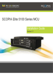
SCOPIA Elite 5100 Series MCU
Installation Guide
Version 7.5
© 2000-2010 RADVISION Ltd. All intellectual property rights in this publication are owned by RADVISION Ltd and are
protected by United States copyright laws, other applicable copyright laws and international treaty provisions.
RADVISION Ltd retains all rights not expressly granted.
This publication is RADVISION confidential. No part of this publication may be reproduced in any form whatsoever or used
to make any derivative work without prior written approval by RADVISION Ltd.
No representation of warranties for fitness for any purpose other than what is specifically mentioned in this guide is made
either by RADVISION Ltd or its agents.
RADVISION Ltd reserves the right to revise this publication and make changes without obligation to notify any person of
such revisions or changes. RADVISION Ltd may make improvements or changes in the product(s) and/or the program(s)
described in this documentation at any time.
If there is any software on removable media described in this publication, it is furnished under a license agreement
included with the product as a separate document. If you are unable to locate a copy, please contact RADVISION Ltd and
a copy will be provided to you.
Unless otherwise indicated, RADVISION registered trademarks are registered in the United States and other territories.
All registered trademarks recognized.
For further information contact RADVISION or your local distributor or reseller.
Installation Guide for SCOPIA Elite 5100 Series MCU Version 7.5, November 2010
http://www.radvision.com
RADVISION | Installation Guide for SCOPIA Elite 5100 Series MCU Version 7.5
Table of Contents
1
About SCOPIA Elite 5100 Series
2
How to Prepare for SCOPIA Elite 5100 Series MCU Installation
About Site Preparation...................................................................................... 3
Unpacking the SCOPIA Elite 5100 Series ................................................................. 4
Verifying the Contents ...................................................................................... 5
Inspecting for Damage ...................................................................................... 5
3
Setting up the SCOPIA Elite 5100 Series MCU
Attaching Mounting Brackets on the SCOPIA Elite 5100 Series MCU ................................. 6
Chassis Lifting Guidelines................................................................................... 7
What to Consider Before Installing the Brackets ....................................................... 7
Installing the Brackets ...................................................................................... 8
Mount Kit Description ................................................................................. 9
Rack Mounting the SCOPIA Elite 5100 Series MCU ...................................................... 9
Attaching the System Ground............................................................................ 10
Shelf Mounting the SCOPIA Elite 5100 Series MCU.................................................... 10
Connecting Cables to the SCOPIA Elite MCU........................................................... 11
Verifying SCOPIA Elite 5100 Series MCU Installation ................................................. 12
4
Performing Initial Configuration of the SCOPIA Elite MCU
Setting the IP Address..................................................................................... 13
RADVISION | Installation Guide for SCOPIA Elite 5100 Series MCU Version 7.5
Table of Contents| i
Accessing the SCOPIA Elite 5100 Series MCU Administrator Interface............................. 15
Changing a User Password ................................................................................ 16
Changing SCOPIA Elite 5100 Series MCU Service Prefix .............................................. 16
How to Set the MCU’s Interface Languages ............................................................ 17
About Supported Languages ........................................................................ 17
Setting the MCU’s User Interface Language...................................................... 18
Setting a Text Overlay Language................................................................... 19
Configuring Protocols for the SCOPIA Elite MCU ...................................................... 20
Configuring H.323 Protocol Settings............................................................... 20
Configuring SIP Server Settings .................................................................... 21
Configuring a Dual-NIC MCU .............................................................................. 24
RADVISION | Installation Guide for SCOPIA Elite 5100 Series MCU Version 7.5
Table of Contents| ii
1
About SCOPIA Elite 5100 Series
SCOPIA Elite 5100 Series enables multiparty multimedia conferencing services for group
conferencing, distance learning, training and video telephony.
The SCOPIA Elite 5100 Series consists of a 1U chassis that contains one Media Blade board.
Figure 1-1 Front Panel of the SCOPIA Elite 5100 Series
RADVISION | Installation Guide for SCOPIA Elite 5100 Series MCU Version 7.5
About SCOPIA Elite 5100 Series | 1
Table 1-1
Chassis Main Features
Grounding and electrostatic discharge
The chassis includes an external grounding 4mm
stud as per the TUV requirement).
Cooling
The chassis supports a single failed fan in the fan
tray.
• AC power supply as the default choice.
• Universal 90-264 VAC power ports.AC power
Power supply
entry includes regular IEC320-C14 filtered AC
inlet and double pole switch located in the rear.
• Thermal shutdown if the unit heats up beyond
its limits.
Table 1-2
SCOPIA Elite 5100 Series Features
Component
Description
STATUS LED
Lights green to indicate normal operation. Lights red to indicate
that an error has occurred and that the Media Blade requires
resetting.
Serial connector
A DB-9 connector that allows you to connect a PC terminal for local
configuration, maintenance and debugging.
100/1000 BASE-T Ethernet RJ-45 connectors that provide the primary LAN connection for the
connectors
IP network port.
Ethernet connector
Link/Activity LEDs
The top part of each Ethernet connector contains two LED
indicators. The right LED lights green when the local IP network link
is active. The left LED lights green if the connection speed reaches
1000 Mbps, and lights orange if the connection speed reaches 100
Mbps.
RESET button
Allows you to reset the Media Blade manually.
Power LED
Lights green to indicate that the power is turned on.
The rear panel is used for connecting the power cable, powering on and off the MCU, and for
grounding the chassis.
Figure 1-2 Rear Panel of SCOPIA Elite 5100 Series MCU
RADVISION | Installation Guide for SCOPIA Elite 5100 Series MCU Version 7.5
About SCOPIA Elite 5100 Series | 2
2
How to Prepare for SCOPIA Elite 5100 Series MCU
Installation
Perform procedures in this section to prepare the site and the SCOPIA Elite 5100 Series MCU
chassis for installation.
• About Site Preparation .........................................................................
• Unpacking the SCOPIA Elite 5100 Series.....................................................
• Verifying the Contents .........................................................................
• Inspecting for Damage .........................................................................
page 3
page 4
page 5
page 5
About Site Preparation
Prior to installing the SCOPIA Elite 5100 Series MCU, you need to verify that your site is suitable
for the MCU. Read this section to learn about the product technical specifications and site
requirements. Ensure to make necessary changes in case you find that the site does not meet any
of the requirements described in this section.
Power system:
• Input: 90-264VAC
• Power supply: single 400W AC supply
• Max. power consumption: DC 335W (50°C) AC 392VA (50°C)
• Heat dissipation: 1145 BTU/Hr (50°C)
Mechanical characteristics:
• Chassis size (W×H×D): 448mm×44mm×480mm (17.6"×1.73"×18.9")
• Rack mount size: 1U×482.6 mm (19")
• Weight: ~13kg (~28.7Lbs)
Environmental requirements:
• Operating Temperature: 0 C° to 45 C° (32 F to 113 F)
• Humidity: 5% to 90% non-condensing
RADVISION | Installation Guide for SCOPIA Elite 5100 Series MCU Version 7.5
How to Prepare for SCOPIA Elite 5100 Series MCU Installation | 3
• Storage and transit temperature: -25 C° to 70 C° (-13 F to 158 F), ambient
• Acoustics 56dBA
Unpacking the SCOPIA Elite 5100 Series
We strongly recommend that you follow safety guidelines described in this section during MCU
unpacking.
Procedure
Step 1
Step 2
Inspect the shipping box to verify that it is not seriously damaged during shipping.
Place the shipping box on a horizontal surface paying attention to the This Side Up symbol on the
shipping box.
Figure 2-1 This Side Up Symbol
Note:
The accessories kit is situated on top of the MCU unit inside the shipping box and can be
damaged if the box is placed upside down. Pay attention to the This Side Up symbol on
the shipping box to handle the box correctly at all times.
Note:
To prevent injury and equipment damage, follow lifting guidelines described in the Safety
Guide when lifting or moving the shipping box.
RADVISION | Installation Guide for SCOPIA Elite 5100 Series MCU Version 7.5
How to Prepare for SCOPIA Elite 5100 Series MCU Installation | 4
Step 3
Cut the plastic straps.
Note:
Step 4
Step 5
Step 6
Step 7
Step 8
The plastic straps are tightly stretched and can hit you when you cut them. To avoid this,
make sure you do not face the side of the box secured by the straps before you cut the
straps.
Cut the strapping tape.
Open the shipping box.
Take the accessories kit out of the shipping box.
Take the MCU unit out of the shipping box.
Carefully open the additional boxes, remove the packing material, and remove the drives and
other contents.
Note:
We recommend that you keep the packaging materials in case you need to repack the
unit.
Verifying the Contents
After opening the shipping box, you need to verify the shipment is complete.
Compare the contents of the shipment with your packing list.
Inspecting for Damage
After you verify that all of the equipment is included, carefully examine the CDEs, cards, power
supplies, and cables for any damage resulting from shipping. If you suspect any damage from
shipping, contact your local freight carrier for procedures on damage claims. If you observe any
physical defects in the items you ordered, contact RADVISION Technical Support for Return
Material Authorization (RMA) form.
Note:
Before proceeding with the installation, verify that all of the ordered parts are present and in good
condition. Keep a record of the parts and serial numbers. If any parts are missing or damaged,
contact your sales representative.
RADVISION | Installation Guide for SCOPIA Elite 5100 Series MCU Version 7.5
How to Prepare for SCOPIA Elite 5100 Series MCU Installation | 5
3
Setting up the SCOPIA Elite 5100 Series MCU
• Attaching Mounting Brackets on the SCOPIA Elite 5100 Series MCU .................... page 6
• Chassis Lifting Guidelines...................................................................... page 7
• What to Consider Before Installing the Brackets........................................... page 7
• Installing the Brackets ......................................................................... page 8
• Rack Mounting the SCOPIA Elite 5100 Series MCU ......................................... page 9
• Attaching the System Ground ................................................................ page 10
• Shelf Mounting the SCOPIA Elite 5100 Series MCU ........................................ page 10
• Connecting Cables to the SCOPIA Elite MCU............................................... page 11
• Verifying SCOPIA Elite 5100 Series MCU Installation...................................... page 12
Attaching Mounting Brackets on the SCOPIA Elite 5100 Series MCU
The MCU mounting kit includes the integral mounting brackets and screws necessary for
performing this procedure.
Attach mounting brackets so that they are aligned with the MCU front panel as shown in Figure 3-1
Figure 3-1 SCOPIA Elite MCU Chassis
RADVISION | Installation Guide for SCOPIA Elite 5100 Series MCU Version 7.5
Setting up the SCOPIA Elite 5100 Series MCU | 6
Chassis Lifting Guidelines
A fully configured SCOPIA Elite 5100 Series MCU chassis weighs approximately 28.7lbs. (13kg.).
The chassis is not intended to be moved frequently. Before you install the MCU, ensure that your
site is properly prepared, so you can avoid having to move the chassis later to accommodate for
power sources and network connections.
Whenever you lift the chassis or any heavy object, follow these guidelines:
• Always disconnect all external cables before lifting or moving the chassis.
• Do not attempt to lift the chassis by yourself; have someone assist you.
• Ensure that your footing is solid, and balance the weight of the object between your feet.
• Lift the chassis slowly; never move suddenly or twist your body as you lift.
• Keep your back straight and lift with your legs, not your back. If you must bend down to lift
the chassis, bend at the knees, not at the waist, to reduce the strain on your lower back
muscles.
Lift the chassis from the bottom. Grasp the underside of the chassis exterior with both hands.
What to Consider Before Installing the Brackets
When planning your rack installation, consider the following guidelines:
• Install the SCOPIA Elite 5100 Series MCU in an open rack whenever possible. If installation in
an enclosed rack is unavoidable, ensure that the rack has adequate ventilation.
• Avoid placing the MCU in an overly congested rack or directly next to another equipment rack.
Otherwise, the heated exhaust air from other equipment can enter the inlet air vents and
cause the MCU to overheat.
• The height of the chassis is 1.73 inches (44mm).
• Maintain a minimum clearance of 3 inches (7.62 cm) on the left and right of the chassis for
the cooling air inlet and exhaust vents.
• Allow sufficient clearance around the rack for maintenance. If the rack is mobile, you can
push it back near a wall or cabinet for normal operation and pull it out when necessary for
maintenance (installing or moving port adapters, connecting cables, or replacing or upgrading
components). Otherwise, allow 19 inches (48.3 cm) of clearance to remove MCU Field
Replaceable Units.
RADVISION | Installation Guide for SCOPIA Elite 5100 Series MCU Version 7.5
Setting up the SCOPIA Elite 5100 Series MCU | 7
Installing the Brackets
You must install the side rails into a rack with square or round holes:
Figure 3-2 Mounting Holes on Rack
1 RU
Rear
Front
207525
1 RU
Note:
If you mount the side rails in holes that are not vertically aligned from side to side, you can damage
the unit.
Procedure
Step 1
On the left and right uprights, determine the vertical position in the rack where the unit will be
installed.
Step 2
The unit height is 1U. Measure the distance between mounting holes and insert the cage nuts
accordingly.
Step 3
Step 4
Ensure the port adapter latch is in the locked position and the screw is tightened.
Ensure the rack breaks are locked or the rack is stabilized.
RADVISION | Installation Guide for SCOPIA Elite 5100 Series MCU Version 7.5
Setting up the SCOPIA Elite 5100 Series MCU | 8
Mount Kit Description
The SCOPIA Elite MCU Rack Mounting Kit contains brackets and screws as shown in Figure 3-3.
Figure 3-3 SCOPIA Elite MCU Rack Mounting
Rack Mounting the SCOPIA Elite 5100 Series MCU
After you have installed the brackets to form a shelf, you can now mount the MCU chassis. Before
mounting the chassis, read the safety guidelines described in the Safety Guide for the MCU.
To rack mount the Cisco Unified Videoconferencing 5000 Series MCU chassis, you need:
• Installed brackets in the location on the rack in which to mount the chassis, as explained in
Installing the Brackets page HIDDEN.
• A Cisco Unified Videoconferencing 5000 Series MCU chassis.
• Two people: This is not a one-person task.
Note:
If you mount the chassis in holes that are not vertically aligned from side to side, you can damage
the unit.
RADVISION | Installation Guide for SCOPIA Elite 5100 Series MCU Version 7.5
Setting up the SCOPIA Elite 5100 Series MCU | 9
Procedure
Step 1
Lift the Cisco Unified Videoconferencing 5000 Series MCU chassis according to the instructions in
the Chassis Lifting Guidelines page 7.
Step 2
Step 3
Step 4
Step 5
Ensure the front of the chassis faces front and place the chassis on the shelf brackets.
Step 6
Slide the chassis toward the front of the rack until the front of the chassis mounting brackets
contact the rear of the center posts.
Step 7
Step 8
Using the rack screws, attach the front of the mounting brackets to the front of the center posts.
Locate one person at the front of the rack and one at the rear.
Position the chassis so that the "L" brackets are inserted into the chassis mounting brackets.
While one person supports the weight of the chassis, the other person must adjust the "L" brackets
to fit tightly into the chassis brackets.
Tighten all screws.
Attaching the System Ground
Before connecting power or turning on power to the SCOPIA Elite 5100 Series MCU, it strongly
recommend that you provide an adequate chassis ground (earth) connection for the chassis.
You must use size 18 AWG (1 mm2) or larger wire, and an appropriate user-supplied ring terminal.
Note:
This equipment must be grounded. Never defeat the ground conductor or operate the equipment
in the absence of a suitably installed ground conductor. Contact the appropriate electrical
inspection authority or an electrician if you are uncertain that suitable grounding is
available.Connect the AC power receptacle to the AC power source with the provided power cable.
Shelf Mounting the SCOPIA Elite 5100 Series MCU
During the shelf mounting procedure you must secure the MCU in its position on a shelf to prevent
it from moving around on the shelf or falling.
Procedure
Step 1
Step 2
Step 3
Verify that the shelf you want to use is properly mounted and secured.
Verify that the shelf can support the MCU weight.
Fix the integral mounting brackets of the MCU to the shelf rails.
RADVISION | Installation Guide for SCOPIA Elite 5100 Series MCU Version 7.5
Setting up the SCOPIA Elite 5100 Series MCU | 10
Connecting Cables to the SCOPIA Elite MCU
Follow the safety guidelines described in the Safety Guide for the SCOPIA Elite MCU during this
procedure, and use the network and the serial cables supplied with the accessories kit.
Procedure
Step 1
Connect the power cable:
a. Turn off the power distribution unit (PDU).
b. On the rear side of the MCU, plug in the power cable into the AC power connector.
Figure 3-4 The AC Power Connector and Power Switch of the SCOPIA Elite MCU
c. On the rear side of the MCU, power on the MCU using the On/Off switch.
d. Turn on the power distribution unit (PDU).
Step 2
On the front side of the MCU, connect the MCU to the switch by plugging a network cable into one
of the Ethernet connectors.
Figure 3-5 The Serial and Ethernet Connectors of the SCOPIA Elite 5100 Series
Note:
Step 3
Both ethernet connectors are used in dual-NIC deployments. A dual-NIC MCU raises
security by using different subnets for media and management. Use the left ethernet
connector for management and the right connector for media. For more information, see
Configuring a Dual-NIC MCU page 24.
Connect the console to the MCU by plugging the serial cable into the serial connectors on the
console and the front side of the MCU.
RADVISION | Installation Guide for SCOPIA Elite 5100 Series MCU Version 7.5
Setting up the SCOPIA Elite 5100 Series MCU | 11
Verifying SCOPIA Elite 5100 Series MCU Installation
After you installed the MCU and performed the initial configuration of it, you need to verify that
MCU is installed and configured correctly.
Procedure
Step 1
Step 2
Step 3
On the front panel, verify that the POWER LED is lit green.
On the front panel, verify that the STATUS LED is lit green.
Check the network connection by verifying that the right LED on the Ethernet connector is lit
green.
Figure 3-6 The MCU Front Panel LEDs
Step 4
Verify that the MCU is ready to be used by creating a conference:
a. From an endpoint dial the MCU IP address.
You access the MCU auto attendant service which plays the video and audio prompts.
b. Press 0 to create a new conference.
c. At a prompt, enter the meeting ID and press #.
The MCU creates the conference and you see the Conference window.
d. Exit the conference by disconnecting the call.
RADVISION | Installation Guide for SCOPIA Elite 5100 Series MCU Version 7.5
Setting up the SCOPIA Elite 5100 Series MCU | 12
4
Performing Initial Configuration of the SCOPIA Elite
MCU
When you finished installing the MCU, you need to perform the initial configuration during which
you configure the basic features. After the initial configuration the MCU should be ready for use.
• Setting the IP Address .........................................................................
• Accessing the SCOPIA Elite 5100 Series MCU Administrator Interface.................
• Changing a User Password ....................................................................
• Changing SCOPIA Elite 5100 Series MCU Service Prefix ..................................
• Setting the MCU’s User Interface Language ...............................................
• Setting a Text Overlay Language ............................................................
• Configuring Protocols for the SCOPIA Elite MCU ..........................................
• Configuring a Dual-NIC MCU ..................................................................
page 13
page 15
page 16
page 16
page 18
page 19
page 20
page 24
Setting the IP Address
You use the serial port on the SCOPIA Elite 5100 Series MCU front panel to assign a new IP address
to your MCU. You must assign the IP address before you connect the MCU to the network.
Before You Begin
Make sure you have these items:
• Dedicated IP address for the MCU
• Dedicated subnet mask for the MCU
• IP address of the default router the MCU uses to communicate over the network
• PC with available serial port and terminal emulator software installed
• Serial cable
RADVISION | Installation Guide for SCOPIA Elite 5100 Series MCU Version 7.5
Performing Initial Configuration of the SCOPIA Elite MCU | 13
Procedure
Step 1
Step 2
Step 3
Step 4
Connect the power cable.
Start the terminal emulation application on the PC.
Set the communication settings in the terminal emulation application on the PC as follows:
•
Baud rate: 9600
•
Data bits: 8
•
Parity: None
•
Stop bits: 1
•
Flow control: None
Turn on the power to the MCU.
A log of the auto-boot events scrolls across the computer monitor.
Step 5
When the message “Press any key to start configuration” appears on the screen, press any key
within 10 seconds.
The network configuration Main menu appears:
Main menu
N: Configure network port values
P: Change the configuration software password
S: Configure network security mode
T: Configure TFTP servers list
A: Advanced configuration menu
Q: Quit
Note:
Step 6
Step 7
Step 8
Step 9
Step 10
If you do not press a key before the countdown ends, the device continues its initialization
and you will need to reboot the device to return to the network configuration Main menu.
Enter N at the prompt to configure default network port values and press Enter.
Enter 2 to change the network configuration.
Enter N at the prompt to enable IPv6 in addition to IPv4.
Enter N at the prompt to enable IP separation.
Enter the IP address you want to assign to the MCU at the Management IP address prompt and
press Enter.
RADVISION | Installation Guide for SCOPIA Elite 5100 Series MCU Version 7.5
Performing Initial Configuration of the SCOPIA Elite MCU | 14
Step 11
Enter the subnet mask without leading zeros at the Enter IP Mask for default device prompt and
then press Enter.
If you are not using a subnet mask, press Enter.
Step 12
Step 13
Step 14
Step 15
Step 16
Press Enter at the Preferred DNS prompt.
Press Enter at the Alternate DNS prompt.
Press Enter at the DNS suffix prompt.
Allow the unit to complete the reboot process. A new emulator session begins.
Close the terminal emulator session.
Accessing the SCOPIA Elite 5100 Series MCU Administrator Interface
The MCU interface is available in these languages:
• English
• Chinese
• Japanese
• Portuguese
• Spanish
• Russian
The default language of the MCU interface is English. When you access the MCU interface, the
login screen is in English unless you choose a different language.
Procedure
Step 1
Step 2
Launch your browser and enter the IP address or the name of the MCU.
If you need to change the MCU interface language, select a language from the Language list.
The login screen is displayed in the language you selected.
Step 3
Enter the Administrator user name and password in the appropriate fields and select Go.
The default global user name is admin. The default password is password.
Note:
If you try to sign in as an Administrator and another Administrator is currently signed in,
the MCU signs you in as a Read only user. The words “Read Only” appear at the top of the
window and a pop-up displays the IP address of the Administrator already signed in. Read
only users cannot edit MCU settings.
RADVISION | Installation Guide for SCOPIA Elite 5100 Series MCU Version 7.5
Performing Initial Configuration of the SCOPIA Elite MCU | 15
Changing a User Password
Only administrators can change a password.
The SCOPIA Elite 5100 Series MCU comes with two preconfigured users: an administrator and an
operator. The password for both preconfigured users is ‘password’. We highly recommend that
you change the default user password for security.
You can change a user password at any time.
Procedure
Step 1
Step 2
Step 3
Step 4
Step 5
Access the MCU Administrator interface.
Select Users
.
Select the Review button
for the user profile you want to modify.
Enter the new password in the Password and the Confirm Password fields.
Select Apply.
Changing SCOPIA Elite 5100 Series MCU Service Prefix
The MCU comes with a single predefined default service (with prefix number 71). The predefined
service is factory tuned to be suitable in most cases for audio and video calls. We recommend
starting with this service and modifying it as necessary to suit your needs.
You can modify existing prefixes to suit your network dialing plan or define new services and add
them to the list.
You must ensure that the service prefix numbers are not identical to the first digits of any of your
network endpoint phone numbers or aliases.
Procedure
Step 1
Step 2
Step 3
Step 4
Step 5
Step 6
Select Configuration
.
Select Conferences.
Locate the Services list section.
Select the Review button
next to the service.
Enter the new prefix number.
Select Apply.
RADVISION | Installation Guide for SCOPIA Elite 5100 Series MCU Version 7.5
Performing Initial Configuration of the SCOPIA Elite MCU | 16
How to Set the MCU’s Interface Languages
• About Supported Languages .................................................................. page 17
• Setting the MCU’s User Interface Language................................................ page 18
• Setting a Text Overlay Language............................................................. page 19
About Supported Languages
SCOPIA Elite MCU has three user interfaces:
•
Administrator interface—the web-based interface used by administrators for configuration
and maintenance tasks.
• Conference Control interface—the web-based interface used by administrators and operators
for conference moderation and video layout control.
• Text overlay on conference video—the set of menus that appear in the conference video.
SCOPIA Elite MCU supports the same languages for the Administrator and Conference Control
interfaces, and a different set of languages for the text overlay.
RADVISION | Installation Guide for SCOPIA Elite 5100 Series MCU Version 7.5
Performing Initial Configuration of the SCOPIA Elite MCU | 17
Table 4-1
Supported Languages in the MCU Interface
Language
Administrator
Interface
Conference Control
Interface
Text Overlay on
Conference Video
English
*
*
*
Chinese (simplified)
*
*
*
Japanese
*
*
*
Portuguese
*
*
Spanish
*
*
Russian
*
*
Hebrew
*
Setting the MCU’s User Interface Language
The procedure in this section explains how to set the language of the MCU Administrator interface
and the Conference Control interface. By default, the interface language is set to English.
Note:
To view Chinese or Japanese fonts properly in the Administrator interface, the computer on which
the web browser is running must support the relevant languages. On a Microsoft Windows operating
system, you can set the default language in Control Panel > Regional and Language Options.
Procedure
Step 1
Select Configuration
in the MCU user interface.
The Setup tab is displayed.
Step 2
Locate the Basics section.
RADVISION | Installation Guide for SCOPIA Elite 5100 Series MCU Version 7.5
Performing Initial Configuration of the SCOPIA Elite MCU | 18
Step 3
Select a language in the Default user interface language list.
Figure 4-1 Basics Section of the Setup Tab
Step 4
Select Apply at the bottom of the Setup tab.
Setting a Text Overlay Language
Perform the procedure in this section to set the language of the text overlay messages.
The text overlay feature is set to English by default.
Procedure
Step 1
Step 2
Step 3
Select Configuration
.
Select Customization.
Select the required language.
Figure 4-2 The Video display messages Section of the Customize Tab
Step 4
Select Apply.
RADVISION | Installation Guide for SCOPIA Elite 5100 Series MCU Version 7.5
Performing Initial Configuration of the SCOPIA Elite MCU | 19
Configuring Protocols for the SCOPIA Elite MCU
Set the MCU protocols by configuring it to work either with the H.323 gateway or with the SIP
Proxy Server, or with both. You can change the protocol-related settings at any time without
resetting the MCU.
• Configuring H.323 Protocol Settings......................................................... page 20
• Configuring SIP Server Settings .............................................................. page 21
Configuring H.323 Protocol Settings
You can configure the H.323 protocol settings to set how the MCU and the gatekeeper interact.
Note
• Changing gatekeeper settings does not reset the MCU, but might disconnect active calls.
• You do need to reset the MCU to disable support for the H.323 protocol.
Procedure
Step 1
Step 2
Step 3
Select Configuration
.
Select Protocols .
Locate the H.323 section.
Figure 4-3 H.323 protocol Section of the Protocols Tab
Step 4
Step 5
Select H.323 to enable the MCU to operate with the H.323 protocol.
Enter the IP address and port number for the gatekeeper.
The default port is 1719.
Step 6
Step 7
Select Apply.
Check the MCU status using the MCU Administrator interface:
a. Enter the MCU IP address or the MCU name into the Internet browser.
b. Enter the Administrator user name and password in the appropriate fields and select Go.
The default global user name is admin. The default password is password.
The Status tab of the Administrator interface opens.
c. Locate the Status Map section. This section is a graphic representation of the MCU chassis
RADVISION | Installation Guide for SCOPIA Elite 5100 Series MCU Version 7.5
Performing Initial Configuration of the SCOPIA Elite MCU | 20
Figure 4-4 The Status Map Showing the Gatekeeper Connection
d. Verify that the MCU is connected to the Ethernet.
e. Verify that the MCU is connected to the Gatekeeper.
Configuring SIP Server Settings
You can configure settings for SIP server profiles which set how the SCOPIA Elite 5100 Series MCU
and the registrar interact.
Depending on connection types supported by the SIP server, MCU supports these transport
connection types for sending messages to SIP server:
• UDP
• TCP
• TLS
Procedure
Step 1
Step 2
Step 3
Step 4
Select Configuration
.
Select Protocols.
Select Enable SIP protocol to enable MCU communication with the SIP server.
Enter the SIP domain of the MCU in the Default SIP domain field as defined in the SIP server.
An example of a SIP domain is company.com.
RADVISION | Installation Guide for SCOPIA Elite 5100 Series MCU Version 7.5
Performing Initial Configuration of the SCOPIA Elite MCU | 21
Step 5
Select Locate automatically to instruct the MCU to automatically locate one of the SIP servers
that are present in the domain,
or
Select Specify and enter the following:
•
An IP address or host name of the SIP server, for example <sipserver>.<company>.com.
Figure 4-5 SIP Protocol Section of the Protocols Tab
•
The communication port number of the SIP server address. The default port is 5060.
•
The transport connection type.
The default is UDP.
Figure 4-6 Type List
Note:
Step 6
The Locate automatically option works only if you have configured a valid IP address at
Configuration > Setup > Network > DNS server1 or DNS server2.
To instruct the MCU to register with a SIP registrar and to send service information to the
registrar, perform these steps:
a. Select Use registrar.
RADVISION | Installation Guide for SCOPIA Elite 5100 Series MCU Version 7.5
Performing Initial Configuration of the SCOPIA Elite MCU | 22
b. Enter the following information:
• The IP address or the host name of the SIP registrar in the IP address field.
• The communication port number of the SIP registrar address.
• The transport connection type for sending registration requests to the registrar according
to the type supported by the SIP registrar.
The default is UDP.
Step 7
Select More.
The Local signaling port section is displayed.
Figure 4-7 Local signaling port Section
Step 8
Enter the number of the signaling port on which the MCU communicates with the SIP server.
The default is 5060.
Step 9
Select Use proxy digest authentication to enable MCU authentication with a SIP server using user
name and password.
Authentication is performed as defined in RFC 2617. This field is disabled by default.
Enter the MCU user name and password. They must match those defined on the SIP server.
Step 10
Select Use registrar digest authentication to enable MCU authentication with a SIP registrar
using user name and password.
Authentication is performed as defined in RFC 2617. This field is disabled by default.
Enter the MCU user name and password. They must match those defined on the SIP server.
Step 11
Select Use ‘Empty Invite’ when sending Invite messages to endpoints to enable the remote
endpoint to indicate preferred audio and video channels.
Step 12
Step 13
Select Apply.
Check the MCU status using the MCU Administrator interface:
a. Enter the MCU IP address or the MCU name into the Internet browser.
RADVISION | Installation Guide for SCOPIA Elite 5100 Series MCU Version 7.5
Performing Initial Configuration of the SCOPIA Elite MCU | 23
b. Enter the Administrator user name and password in the appropriate fields and select Go.
The default global user name is admin. The default password is password.
The Status tab of the Administrator interface opens.
c. Locate the Status Map section. This section a graphic representation of the MCU chassis
d. Verify that the MCU is connected to the Ethernet.
e. If you registered the MCU with SIP registrar, verify that the MCU is connected to the SIP
Server.
Configuring a Dual-NIC MCU
The SCOPIA Elite MCU can be configured to work as a dual-NIC device, improving security by
enabling the management data to be on a separate subnet from the media and signaling.
Media refers to the actual content of the video call: audio, video and data presentations.
Management data refers to messages of coordination, control and monitoring, like between your
web browser and the MCU for configuration, or between the MCU and the SCOPIA
iVIEW Management Suite for call coordination. Management signals are sent in protocols like
HTTP, XML, SNMP and so on.
Separating these types of data on different subnets improves security because management data
typically remains on subnets within the enterprise, while the media of video calls is often required
to traverse firewalls and reach endpoints outside the enterprise.
Dual-NIC functionality requires two subnets, where each subnet must have its own router or
default gateway.
RADVISION | Installation Guide for SCOPIA Elite 5100 Series MCU Version 7.5
Performing Initial Configuration of the SCOPIA Elite MCU | 24
Procedure
Step 1
Connect the network cable of the management subnet to the left ethernet port only, and activate
the unit.
Figure 4-8 Two ethernet connectors of the SCOPIA Elite MCU
Note:
Step 2
Step 3
Step 4
Do not connect the media subnet cable until the MCU has been reset at the end of this
procedure.
Access the MCU in a web browser and login.
Select the Configuration
tab.
Select the Advanced IP (Dual-NIC) Configuration check box to expand that section of the page.
Figure 4-9 Dual-NIC configuration for management and media subnets
Step 5
Under Management Interface, enter the IP information for the management subnet:
a. Enter the MCU’s IP address on the management subnet in the Primary IP address field.
RADVISION | Installation Guide for SCOPIA Elite 5100 Series MCU Version 7.5
Performing Initial Configuration of the SCOPIA Elite MCU | 25
b. Enter the IP address of the management subnet’s router in the Router IP field.
Note:
The router IP address on this subnet must be distinct from the router on the media subnet.
If both cables are connected to the same router, you must use the MCU’s VLAN
functionality to send both media and management data to the same router. It will then
route the media and management data to different virtual subnets (or VLANs). For more
information on VLAN functionality, see the online help.
Step 6
Enter the IP information for the media and signaling subnet in the Media and Signaling Interface
section.
Step 7
Step 8
Step 9
Select Apply at the bottom of the page.
The system restarts, terminating any live conferences. Select Yes to restart.
Connect the cable for the media and signaling subnet to the right-hand ethernet port.
Note:
To access the management interface from an additional subnet to the one mentioned
above, select the More button at the bottom of the expanded section (Figure 1-2 on
page 2), to open the Additional Management Networks section. Enter the IP address of
the additional subnet’s router.
RADVISION | Installation Guide for SCOPIA Elite 5100 Series MCU Version 7.5
Performing Initial Configuration of the SCOPIA Elite MCU | 26
www.radvision.com
About RADVISION
RADVISION (NASDAQ: RVSN) is the industry’s leading provider of market-proven products and technologies for
unified visual communications over IP and 3G networks. With its complete set of standards based video networking
infrastructure and developer toolkits for voice, video, data and wireless communications, RADVISION is driving the
unified communications evolution by combining the power of video, voice, data and wireless – for high definition
video conferencing systems, innovative converged mobile services, and highly scalable video-enabled desktop
platforms on IP, 3G and emerging next generation networks. For more information about RADVISION, visit
www.radvision.com
USA/Americas
T +1 201 689 6300
F +1 201 689 6301
[email protected]
EMEA
T +44 20 3178 8685
F +44 20 3178 5717
[email protected]
APAC
T +852 3472 4388
F +852 2801 4071
[email protected]
This document is not part of a contract of license as may be expressly agreed RADVISION is registered
trademarks of RADVISION, Ltd. All trademarks recognized. All rights reserved © 2010 RADVISION, Ltd.