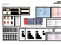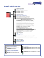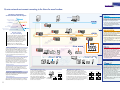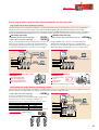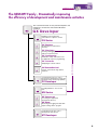
1
Module
Mitsubishi Electric Corporation Nagoya Works is a factory certified for
ISO14001 (standards for environmental management systems) and
ISO9001 (standards for quality assurance management systems)
http://www.MitsubishiElectric.co.jp/english/
An automation solution specific to your needs
The MELSEC Q series offers ‘total and global’ solutions for a diverse range of applications.
The MELSEC Q series continues to advance the state of the art in automation control.
The Q series is an enhancement of Mitsubishi Electric’s vast automation system expertise, whilst inheriting the technical
know how of the MELSEC A and QnA series.
This unique series is able to integrate four types of automation control, sequence, motion, process, and information (PC
based) onto a single system. Therefore, offering significant benefits for the user in terms of development, functionality,
performance, and maintenance.
Sequence control
Process control
Motion control
Information control
Analog Modules
Temperature Input Modules
Temperature Control Modules
Module
High Speed Counter Modules
Positioning Modules
Q series lineup
CPU Modules
Network/Information Processing Modules
PLC CPU
Process CPU
High Performance Model QCPU
CPU type
Q00JCPU
Q00CPU
Q01CPU
Program capacity
8k steps
8k steps
14k steps
Number of I/O points
256 points
1024 points
1024 points
CPU type
Q02CPU
Q02HCPU
Q06HCPU
Q12HCPU
Q25HCPU
Program capacity
28k steps
28k steps
60k steps
124k steps
252k steps
Number of I/O points
4096 points
4096 points
4096 points
4096 points
4096 points
CPU type Program capacity
Q12PHCPU 124k steps
Q25PHCPU 252k steps
Number of I/O points
4096 points
4096 points
Power Supply Modules
Serial Communication Modules
QJ71C24N
QJ71C24N-R2
QJ71C24N-R4
MELSECNET/H Modules
QJ71LP21-25
QJ72LP25-25
QJ71LP21S-25 QJ72LP25G
QJ71LP21G
QJ72LP25GE
QJ71LP21GE
QJ72BR15
QJ71BR11
Motion CPU
CPU type
Q172CPUN
Q173CPUN
CC-Link/LT Module
QJ61CL12
Ethernet Modules
QJ71E71-100
QJ71E71-B5
QJ71E71-B2
Basic Model QCPU
FL-net (OPCN-2) Interface Modules
QJ71FL71-T-F01
QJ71FL71-B5-F01
QJ71FL71-B2-F01
MELSECNET/H PC I/F board
Q80BD-J71LP21-25
Q80BD-J71LP21G
Q80BD-J71LP21GE
Q80BD-J71BR11
Number of control axes
8 axes
32 axes
AS-I Master Module
QJ71AS92
Intelligent Communication Modules
QD51
QD51-R24
CC-Link Module
QJ61BT11N
Memory Cards
Intelligent Function Modules
CC-Link PC I/F board
A80BDE-J61BT11
A80BDE-J61BT13
Analog Modules
A/D Converter Modules
Q64AD-GH
Q62AD-DGH
Q64AD
Q68ADV
Q68ADI
D/A Converter Modules
Q62DA-FG
Q62DA
Q64DA
Q68DAV
Q68DAI
Positioning Modules
QD75P1
QD75P2
QD75P4
QD75D1
QD75D2
QD75D4
QD75M1
QD75M2
QD75M4
Temperature Control Modules
Q64TCTT
Q64TCTTBW
Q64TCRT
Q64TCRTBW
Channel-Isolated Pulse
Input Module
QD70P8-G
Temperature Input Modules
Q64TDV-GH
Q64TD
Q64RD-G
Q64RD
QD70P4
QD70P8
High Speed Counter
Modules
QD62
QD62D
QD62E
Accessories
Q61SP<Slim type>
Q61P-A1
Q61P-A2
100 to 120VAC input 200 to 240VAC input 100 to 240VAC input
5VDC 2A output
5VDC 6A output
5VDC 6A output
SRAM cards
Q2MEM-1MBS
Q2MEM-2MBS
Flash cards
Q2MEM-2MBF
Q2MEM-4MBF
PC card adaptor
Q2MEM-ADP
QY70
16mA/point
QY71
16mA/point
QY80
0.5A/point
QY81P
0.1A/point
Q35SB
CPU
Q312B
Power supply
Q65B
8 I/O slots
Q38B
12 I/O slots
* Only the slim type power supply
module (Q61SP) can be used.
* This does not support the Process
CPU.
5 I/O slots
Q35B
8 I/O slots
2 I/O slots
Q63B
Power supply
5 I/O slots
Q33SB
5 I/O slots
3 I/O slots
Extension base unit
(Power supply module
not required; can be extended)
Connection Cable
QC30R2
Connector Disconnection Prevention Holder
Q6HLD-R2
Interrupt Module
QI60
Blank Cover
QG60
MELSOFT
5 I/O slots
GX Developer
Q55B
Q68B
12 I/O slots
QC05B (0.45m)
QC06B (0.6m)
QC12B (1.2m)
QC30B (3.0m)
QC50B (5.0m)
QC100B (10.0m)
Q52B
Power supply
3 I/O slots
Extension base unit
(Power supply module required;
can be extended)
Power supply
Transistor
12 to 24VDC
(source)
IDC Terminal Block Adaptor, Dedicated Tool
Q6TA32
Q6TA32-TOL
Extension Cables
Q33B
Q32SB
Transistor
5 to 12VDC
(sink)
Power supply
3 I/O slots
CPU
Transistor
Transistor
Triac
12 to 24VDC 12 to 24VDC
100 to 240VAC
(sink)
(sink/source)
QX48Y57
7 points
0.5A/point*2
QY18A
QY68A
8 points
2A/point
2A/point
QY40P
QY10
QY22
0.1A/point
16 points
2A/point
0.6A/point
QY50
0.5A/point
QY41P
0.1A/point
32 points
QH42P
0.1A/point*2
QY42P
64 points
0.1A/point
*2: Output specifications for I/O composite module
Main base unit
(Power supply module required;
can be extended)
Power supply
2 I/O slots
Main base unit
CPU
Main base unit
(Power supply module required;
cannot be extended)
Power supply
CPU
Relay
24VDC,
240VAC
Spring clamp Terminal Block
Q6TE-18S
Other Modules
Power supply
Slim type main base unit
Output Modules
Number of
O/P points
Connectors for I/O Modules
40-pin connector type
A6CON1 (soldering type)
A6CON2 (crimp-contact type)
A6CON3 (pressure-displacement type)
A6CON4 (soldering type)
Base Units, Extension Cables
CPU
Number of 100 to 120V 100 to 240V
24VDC
5/12VDC
24VDC
(positive common) (positive/negative common) (negative common)
I/P points
AC
AC
8 points
QX48Y57*1
QX28
QX40
16 points
QX10
QX70
QX80
QX40-S1
QX41
32 points
QX71
QX81
QX41-S1
QH42P*1
QX42
QX82
64 points
QX72
QX42-S1
QX82-S1
*1: Input specifications for I/O composite module
Power supply
Input Modules
DIN rail Adapter
Q6DIN1
Q6DIN2
Q6DIN3
37-pin D sub connector type
A6CON1E (soldering type)
A6CON2E (crimp-contact type)
A6CON3E (pressure-displacement type)
Power supply
CPU
Q64P
Q63P
24VDC input 100 to 120/200 to 240VAC input
5VDC 8.5A output
5VDC 6A output
Power supply
CPU
Q62P
100 to 240VAC input
5VDC 3A output
24VDC 0.6A output
ATA cards
Q2MEM-8MBA
Q2MEM-16MBA
Q2MEM-32MBA
Batteries
Q6BAT
Q7BAT (-SET)
Q2MEM-BAT (for SRAM memory card)
Q612B
* The slim type power supply module (Q61SP) cannot be mounted.
MELSEC PLC programming software
GX Simulator
MELSEC PLC simulation software
GX Explorer
Project control tool
GX Converter
Excel/text data converter
GX Configurator
Intelligent function module
setting and monitor tool
GX RemoteService-I
Remote access tool
PX Developer
FBD software package
for Process control
MT Developer
Integral startup support software
for Q Motion
MX Component
ActiveX® library for communication
MX Sheet
Excel communication support tool
Multiple solutions for a vast range of applications
Sequence Control
Q series CPU lineup provides answers
for a vast range of application requirements.
[PLC CPU]
The Q series lineup covers a various range of applications be it, PLC,
process, motion, or information control. The basic model QCPU range
is designed ideally for small scale applications. With the unique
Multiple CPU functionality, each process area of the application can
be selectively controlled by different CPUs situated on the same main
base unit. Therefore, this lineup provides an ideal solution for each
required application.
Process Control
[Process CPU]
Multiple CPU
Motion Control
[Motion CPU]
Information Control
[PC CPU]
Combine the CPUs to fit specific application requirements,
from basic sequence control to advanced multiple CPU control.
Combine upto 4 CPUs on a single Q series system to provide the ideal solution for your
application.
PLC CPU
Basic Model QCPU
Q00JCPU • Program Capacity: 8K steps • Number of I/O Points: 256 points
• Number of I/O device points: 2048 points
• Integrated CPU with power supply and 5 slots
Q00CPU
• Program Capacity: 8K steps • Number of I/O Points: 1024 points
• Number of I/O device points: 2048 points
Q01CPU
• Program Capacity: 14K steps • Number of I/O Points: 1024 points
• Number of I/O device points: 2048 points
High Performance Model QCPU
Q02CPU
Q02HCPU
Q06HCPU
Q12HCPU
Q25HCPU
• Program Capacity: 28K steps • Number of I/O Points: 4096 points
• Number of I/O device points: 8192 points
• Program Capacity: 28K steps • Number of I/O Points: 4096 points
• Number of I/O device points: 8192 points
• Program Capacity: 60K steps • Number of I/O Points: 4096 points
• Number of I/O device points: 8192 points
• Program Capacity: 124K steps • Number of I/O Points: 4096 points
• Number of I/O device points: 8192 points
• Program Capacity: 252K steps • Number of I/O Points: 4096 points
• Number of I/O device points: 8192 points
High performance CPUs with a diverse and powerful process control instruction set.
Process CPU (MELSEC Process Control)
Q12PHCPU • Program Capacity: 124K steps • Number of I/O Points: 4096 points
• Number of I/O device points: 8192 points
Q25PHCPU • Program Capacity: 252K steps • Number of I/O Points: 4096 points
• Number of I/O device points: 8192 points
Designed for next generation's high-speed motion and multi-axis control.
Motion CPU
Q172CPUN • For 8-axis control
Q173CPUN • For 32-axis control
A fully featured Microsoft™ Windows™ personal computer directly on the Q Series base unit.
Personal Computer CPU
[Partner products]
Offers unlimited open control opportunities while maintaining tight integration with other
Q Series system components.
See pages 35 and 36 for more information on partner products.
High performance and flexibility on a small footprint
Mounting Area
In the Q series, 2, 3, 5, 8 and 12 I/O slots main base units are available. The mounting area can be further reduced by using the slim type base unit.
Mounting Area
Slim type main base unit
(Depth: 98mm)
Main base unit
98mm
98mm
2 slots 114mm
3 slots 142mm
5 slots 197.5mm
3 slots 189mm
5 slots 245mm
8 slots 328mm
12 slots 439mm
Note) The slim type base cannot be used with the process CPU.
Mounting Freedom
Choose from 2, 3, 5, 8 and 12 I/O slot bases to design the best system for the
required application. Connect extension bases directly by using cables alone.
Therefore, no need for network modules, adapters, or configuration software to
distribute base units over an extended distance. Extension bases that do not
require a power supply module are available to further reduce space and costs.
Base unit types (power supply module required)
Number of I/O Slots
3
5
8
12
Main Base
Q33B
Q35B
Q38B
Q312B
Extension Base Mounting Dimensions (mm)
Q63B
189 × 98
Q65B
245 × 98
Q68B
328 × 98
Q612B
439 × 98
Types of slim type main base units (power supply module required)
Number of I/O Slots
2
3
5
Main Base
Q32SB
Q33SB
Q35SB
Base unit types (Requires no power supply module)
Mounting Dimensions (mm)
114 × 98
142 × 98
197.5 × 98
Number of I/O Slots
2
5
Extension Base
Q52B
Q55B
Mounting Dimensions (mm)
106 × 98
189 × 98
Note) The slim type main base unit cannot be connected with an extension base. Also, the process CPU cannot be used.
Up to 7 Extension Bases Connectable
Up to seven extension bases (eight when counting the main base)
can be connected to accept up to 64 modules. Also, the overall
distance of extension cables is max. 13.2m, enabling high freedom
for designing the system base layout.
Q00JCPU
Q00CPU
Q01CPU
Q02CPU
HighQ02HCPU
Performance Q06HCPU
Q12HCPU
Model
Q25HCPU
Process Q12PHCPU
Q25PHCPU
CPU
Basic
Model
Main base
Max. 64 modules
Seventh extension base
Number of Extension
Number of
Overall Extension
Base Units
Loaded Modules Cable Length (m)
CPU
2 (max.)
16 (max.)
4 (max.)
24 (max.)
13.2 (max.)
7 (max.)
64 (max.)
*If a 12-slot base is used, the maximum number of I/O, intelligent function and network
modules mounted is 16/24/64 respectively.
Overall distance:
13.2 m
Number of Control I/O Points
The Q series can control a maximum of 8192 points
(input device points) in a remote I/O network such as
CC-Link, or a maximum of 4096 points (I/O points) for
direct I/O only.
Note 1) Number of I/O points on main and extension bases directly
controllable by a CPU module.
Note 2) Total number of I/O points on main and extension bases directly
controllable by a CPU module and I/O points that can be
controlled as remote I/O by a remote I/O network.
CPU
Q00JCPU
Q00CPU
Q01CPU
Q02CPU
HighQ02HCPU
Performance Q06HCPU
Model
Q12HCPU
Q25HCPU
Process Q12PHCPU
CPU
Q25PHCPU
Basic
Model
Number of I/O Points (Note 1) Number of I/O Device Points (Including remote I/O points) (Note 2)
256
1024
4096
2048
8192
Increased Operation Processing Speeds
Q series offers some of the highest processing performance on the market today; basic instruction processing time is 34ns and PC MIX
value is 10.3. By Mitsubishi's own “PC-MIX” performance metric, it is about 5 times faster than A2USHCPU-S1 and about 2.7 times faster
than the Q2ASHCPU. The CPU has dramatically increased floating-point operation speeds for PID and other arithmetic functions. The PCMIX aims to replicate real-word application performance by executing a mixed instruction set.
CPU operation processing speeds
PC MIX value comparison
High-performance Model Process CPU
Basic Model
Q01CPU
Q00CPU
2.0
Q00JCPU
A2SHCPU
Instruction
Q00JCPU Q00CPU
Q02CPU
Q02HCPU
Q06HCPU Q12PHCPU
Q12HCPU Q25PHCPU
Q25HCPU
100ns
100ns
550ns
350ns
500ns
49.5µs
2.7
79ns
158ns
632ns
237ns
395ns
1815ns
4.4
34ns
68ns
272ns
102ns
170ns
782ns
10.3
1.6
5 times faster
0.5
PC MIX value (instruction/µs)
Q25HCPU
10.3
Q2ASHCPU
A2USHCPU-S1
Q01CPU
CPU
2.7
3.8
2.0
5 times faster
PC MIX value (instruction/µs)
LD (LD X0)
OUT (OUT Y0)
Timer (OUT T0 K5)
Transfer (MOV D0 D1)
Addition (+ D0 D1)
Floating-point addition (E+)
PC MIX value (Instruction/µs)
200ns
200ns
1100ns
700ns
1000ns
65.5µs
1.6
160ns
160ns
880ns
560ns
800ns
60.5µs
2.0
* The PC MIX value is the average number of instructions such as the basic and data processing instructions
executed in 1 µs. A larger value indicates a higher processing speed.
Program Capacities and Large Standard RAM Capacities
To construct small to large scaled systems, the Q
series has a wide variation of CPU modules having 8k
to 252k step program capacities and up to 256k bytes,
large-capacity standard RAMs, to meet the application
requirements from basic sequence control up to
complex multi-discipline applications.
A standard ROM (flash ROM) is built-in to enable
ROM operation without a memory card.
The efficient use of memory space allows the CPU to
contain twice the program of previous Mitsubishi
controllers (AnSHCPU).
Program Capacities Device Memory Standard RAM Standard ROM Memory Card
(Steps)
(Words)
(Bytes) (Note 3)
(Bytes)
(Number of slots)
58k
Q00JCPU
No
Basic
8k
Q00CPU
18k
No
Model
94k
128k
Q01CPU
14k
Q02CPU
64k
28k
112k
Q02HCPU
High128k
240k
60k
Performance Q06HCPU
1
496k
29k
124k
Q12HCPU
Model
1008k
252k
Q25HCPU
256k
496k
124k
Process Q12PHCPU
1008k
252k
Q25PHCPU
CPU
CPU
Note 3) Memory that stores the data used in sequence programs such as file registers and local devices
(with the exception of Basic Model CPU). As a built-in type RAM, the sequence program having a lot
of file registers and local devices stored in standard RAM can run rapidly.
Extended Memory
The High-Performance Model QCPU and Process CPU accepts a range of optional memory cards that expand the processor's capacity up
to 32MB. Memory types available are SRAM card (1MB/2MB), flash card (2MB/4MB), or ATA card(8MB/16MB/32MB).
Depending on the memory used, storage for general purpose files such as Adobe™ Acrobat™, or CAD files is possible directly in the CPU,
which allows system documentation to reside directly in the controller. Storage for machine comments and file register data is also possible.
Memory capacity
Type
SRAM card
FLASH card
ATA card
Memory card type
Q2MEM-1MBS
Q2MEM-2MBS
Q2MEM-2MBF
Q2MEM-4MBF
Q2MEM-8MBA
Q2MEM-16MBA
Q2MEM-32MBA
Memory card capacity Number of storable files (files)
1011.5k bytes (Note 4)
256
2034k bytes (Note 4)
288
2035k bytes
4079k bytes
7940k bytes (Note 4)
512
15932k bytes (Note 4)
31854k bytes (Note 4)
Note 4) The SRAM card and ATA card memory capacity is the value after formatting.
Memory card
All device comments
Extended file registers
(when SRAM card/flash card is used)
Program, MM/DD/YY version
Standard ATA supported files
(when ATA card is used)
Advanced multi-disciplinary automation that reaches beyond the
Multiple CPU System Configuration
The Q series can combine multiple CPUs together on the same
system to build the required application configuration. Control of
I/O modules can be segmented between different CPUs. CPUs
communicate with each other via shared memory, and can
increase system performance by distributing tasks between
different CPUs. A variety of methods exist for controlling the
methods by which CPUs communicate, but in each case the
development effort is simplified by available software tools.
Management
Management
Management
Install up to 4 CPUs.
Modules are managed CPU-by-CPU.
Use standard Q series I/O and intelligent function
modules (Note 1).
Note 1) There are restrictions on the number and versions for intelligent
function modules. Check details in the Q series data book.
Integration of Process CPU, Motion CPU, and PC CPU
The Q series multiple CPU system function allows PLC CPU,
process, motion, and personal computer CPUs to be mounted
together, enabling utilization of their respective strong points and
design of an optimal system.
Loop control/analog processing
Sequence control
Process control
Motion control
Information control
Note) Only the following combinations can be used with the Basic Model.
· Basic Model CPU + Motion CPU
· Basic Model CPU + PC CPU
· Basic Model CPU + Motion CPU+ PC CPU
I/O control
Process Control
Process CPU
Q series offers a feature that rivals those of costly DCS systems at a fraction of the cost. Q Series is adept at the automation of
process systems with the simple addition of one or more process CPUs to the controller. The process CPUs are complemented by
a range of channel-isolated high resolution analog I/O modules with online change (hot-swap) capability, and the PX Developer
function block programming software environment. (Refer to the “MELSEC Process Control Catalog” for more information on the process CPU.)
¡The “Process CPU” builds on the capability of the equivalent sequence CPU with the addition of an array of powerful
process instructions.
¡“Channel-isolated high resolution analog module” further enhance process control using the PLC.
¡Combine the Process CPUs with the redundant network capabilities of the MELSECNET/H control level network.
This offers high performance, robust, and deterministic communications between multiple Q Series systems,
regardless of their assigned control tasks.
Monitoring/
control room PC
Monitoring/
control room PC
GX Developer
PX Developer
MELSECNET/H, Ethernet (10/100Mbps)
· Q process CPU
HMI/GOT
· Q process CPU
· Channel-isolated/
non-isolated analog module
· I/O module
RS-232/USB
Engineering
PC
Reaction can control
· Mitsubishi product
· Partner maker product
MELSECNET/H, Remote I/O network
Remote I/O station
Remote I/O station
· Connector type
analog module
· Channel-isolated/
non-isolated analog module
· I/O module
Fluid level control
Servo
amplifier
Servo
motor
Servo
motor
Host device
* SSCNET is a network where the motion CPU and servo amplifiers are connected with
minimum wiring by high-speed serial communication.
System configuration example
Servo
amplifier
Heating furnace control
· Q process CPU
boundaries of traditional controllers
Motion Control
Motion CPU
Mitsubishi Electric Motion controller realizes high-speed control of up to 32 axes (96 axes per Q series system) directly
from the motion CPUs with no intermediate motion control modules. This offers large cost savings, especially when
complex wiring is eliminated due to the “daisy-chain” connection of Mitsubishi intelligent digital servos. (Refer to the “Motion
Controller Catalog” for more information on the Motion CPU.)
¡0.88ms motion operation cycle time assures high performance operation, even with high-speed cam profile emulation.
¡Together with the shortened communication cycle time (0.88ms), the synchronization performance and
speed/positioning control accuracy is substantially improved.
¡Motion CPU can be used together with any type of Q series CPU as required.
¡Via Mitsubishi's high performance SSCNET motion network technology, Q series offers significant engineering and
operation benefits for motion control.
* SSCNET is a high-speed serial communication network that connects the motion CPU and servo amplifier.
System configuration example
Servo amplifier
PLC CPU + Motion CPU
Servo amplifier
Servo motor
Servo motor
Information Control
PC CPU
Q series is unique in being able to mount a full-featured Windows™ PC in a robust industrial
format directly on the Q series base unit. This offers the potential to combine it with other Q
series CPU types, therefore fully integrating it into the Q I/O system to give complete access
to all I/O modules and networking, allowing maximum design flexibility.
¡Industrial specification level environmental and noise performance specifications.
¡Choose HDD or silicon disk mass storage depending on the operating environment.
¡Utilize third party PC applications available for Microsoft™ Windows™, offering a virtually
unlimited application scope.
¡Includes a wide variety of ports and connections to add third party hardware devices.
Note) The PC CPU is manufactured by CONTEC, Co., Ltd. Refer to the “Partner Products” on pages 35 and 36 for more information.
Seamless development with full range of networking hierarchy.
Networking support at all levels of the automation
hierarchy, scalable to fit any application size
Modern plant systems require networking at many different levels.
With Q series, Mitsubishi offers a networking solution that matches
these specific requirements. The Mitsubishi solution ranges from top
level factory LAN 100Mbit Ethernet, mid-level shop floor control
MELSECNET/H, down to device level CC-Link, and CC-Link/LT. The
open network CC-Link, which originates from Japan, is a SEMI
certified wire saving network, providing the seamless networking
required with modern applications. Therefore, the Q series provides a
range of network types within each level of the hierarchy to ensure the
right solution is provided.
Between factory departments
(information control)
Within factory
(production control)
Within line
(device control)
Within panel
/devices
(device and
I/O control)
Network modules overview
Enterprise level network
Ethernet Modules
QJ71E71-100 •10BASE-T/100BASE-TX
QJ71E71-B5 •10BASE-5
QJ71E71-B2 •10BASE-2
Control level network
MELSECNET/H Modules
PLC-to-PLC Network: Control station/normal
station, Remote I/O network: Master station
QJ71LP21-25 •Optical fiver cable •Duplex loop •25Mbps/10Mbps
QJ71LP21S-25 •Optical fiver cable •Duplex loop •25Mbps/10Mbps
•With external power supply function
QJ71LP21G •Optical GI-50/125 cable •Duplex loop •10Mbps
QJ71LP21GE •Optical GI-62.5/125 cable •Duplex loop •10Mbps
QJ71BR11 •Coaxial cable •Simplex bus •10Mbps
Remote I/O Network: Remote I/O station
QJ72LP25-25 •Optical fiver cable •Duplex loop •25Mbps/10Mbps
QJ72LP25G •Optical GI-50/125 cable •Duplex loop •10Mbps
QJ72LP25GE •Optical GI-62.5/125 cable •Duplex loop •10Mbps
QJ72BR15 •Coaxial cable •Simplex bus •10Mbps
MELSECNET/H PC I/F board (PCI bus)
PLC-to-PLC Network: Control station/normal station
Q80BD-J71LP21-25 •Optical fiver cable •Duplex loop •25Mbps/10Mbps
Q80BD-J71LP21G •Optical GI cable •Duplex loop •10Mbps
Q80BD-J71BR11 •Coaxial cable •Simplex bus •10Mbps
Device level network
Modules
QJ61BT11N •Master station/local station •CC-Link Ver. 2 compatible
CC-Link PC I/F board (PCI bus)
A80BDE-J61BT13 •Local station •CC-Link Ver. 1 compatible
A80BDE-J61BT11 •Master station/local station •CC-Link Ver. 1 compatible
Sensor level network
Module
QJ61CL12 •Master station
Others
Serial Communication Modules
FL-net Modules
QJ71C24N •RS-232 1CH •RS-422/485 1CH
QJ71C24N-R2 •RS-232 2CH
QJ71C24N-R4 •RS-422/485 2CH
QJ71FL71-T-F01 •10BASE-T •OPCN-2 Version 2.00 compatible
QJ71FL71-B5-F01 •10BASE-5 •OPCN-2 Version 2.00 compatible
QJ71FL71-B2-F01 •10BASE-2 •OPCN-2 Version 2.00 compatible
Intelligent Communication Modules
(BASIC program execution module)
AS-i Module
QD51 •RS-232 2CH
QD51-R24 •RS-232 1CH •RS-422/485 1CH
QJ71AS92 •Master station, AS-i Standard Version 2.11 compatible
Q series network environment connecting to the future for more freedom.
Seamless integration
of the network over all layers
Enterprise level network
GX Developer
Ethernet represents the top layer of the network
hierarchy used to transfer information around a
plant and between different departments. Use this
to establish a link to SCADA and other production
and quality control management systems.
<Between factory departments>
Enterprise level network
¡100base-T connections provide easy integration
into the existing plant LAN infrastructure
¡Simple set-up via standard configuration
tools in GX Developer
<Within factory>
Control level network
<Within line>
Device level network
Control level network
<Within panel and devices>
Sensor level network
MELSECNET/H is one step down from Ethernet
and allows communication between controllers on
a line within a plant department. MELSECNET/H
offers high performance, fault tolerant,
deterministic communications for line interlocking
and synchronization between different processes.
Q series support
for open networking.
Q series provides extensive support for applications
requiring a diverse range of 3rd party devices on
the same network. An example is the open CCLink device network, which originated from Japan
through Mitsubishi, and is now administered by the
CC-Link Partner Association (CLPA). CC-Link is a
SEMI certified network, with many products
available from over 500 different partner
companies, with over 1.5 million installed nodes.
¡Maximum 25Mbps high-speed communication
¡Large capacity link device: 16,384 points
each for bits and words
¡Improved reliability using duplex optical fiber
loop
Device level network
Seamless communication
The primary reason for a device level network is to
link a controller to numerous different devices to
reduce wiring costs while adding additional
benefits such as improved diagnostic capability.
Together with SEMI certification, CC-Link provides
an open device level network with enhanced
flexibility in system design and configuration.
Q series combines enterprise, control, and device level networks
together through Ethernet, MELSECNET/H, and CC-Link to
allow easy information access, no matter what level it resides on
the network hierarchy. It is possible to “drill down” from a high
level Ethernet down through multiple network layers, to program
the PLC just by having GX Developer installed on the PC.
¡Maximum 10Mbps high-speed communication
¡Link device remote I/O points: 8192
¡Integrate other 3rd party manufacturers into
the Q series system
Event Interrupt
Some network and intelligent function modules include an
event interrupt function that can interrupt the high
performance QCPU program. With this function, the CPU
can rapidly respond to an event that occurs asynchronously
with the program scan of the PLC, e.g. data receiving from
a network or value compare of a high-speed counter.
Sensor level network
Remote password
The High-Performance Model QCPU includes a remote
password function to provide additional security over
remote access. The remote password can be changed or
deleted as from within the parameters.
External power supply input capability
Data link can be maintained even if the PLC power fails
by using the QJ71LP21S-25 module with external power
supply input for MELSECNET/H.
Network diagnostics
GX Developer includes extensive built-in diagnostic tools for Ethernet,
MELSECNET/H, CC-Link, and CC-Link/LT. Refer to page 21 for details.
MELSECNET/H Remote I/O Network
MELSECNET/H PC interface cards
Q series provides the capability to include
generic PCs on the MELSECNET/H
network via a wide range of PCI interface
cards. The software drivers included with
these cards allow system integration of 3rd
party systems, while also maintaining
compatibility with existing MELSECNET/10 MELSECNET/H
interface card
installations. Including extensive RAS
(PCI BUS)
Q80BD-J71LP21-25
functions for error detection.
QJ71LP21-25
QJ71LP21-25
QJ71LP21-25
MELSECNET/H offers the capability to locate remote bases
containing Q series I/O modules on a 25Mbit control level network.
The key benefit of this is that complex distributed I/O systems can be
built using the same I/O modules as the controller itself. Hence
systems that need more than distributed I/O blocks on a network can
be addressed with Q Series. Any other station on the network can be
accessed from each remote I/O station. In addition, by incorporating
the process CPU, redundant remote I/O systems can be realized by
using MELSECNET/H master and standby master stations.
QJ71LP21-25
QJ72LP25-25
Remote
master
QJ72LP25-25
QJ72LP25-25
At the lowest hierarchial network level, sensor
level networks can still reduce wiring costs inside
panels between simple discrete devices such as
push-buttons and some sensors. Q series fully
supports this with the sensor level version of CCLink, CC-Link/LT. This new addition to the CC-Link
family includes tremendous flexibility and cost
savings through its innovative connection
technology, which does not require cutting/stripping
of the network cable to make connections.
¡Easy connections with dedicated connectors
¡Use I/O points effectively by incorporating
number of points mode (4 points, 8 points, 16
points).
¡The maximum number of link points is 1024
points in the 16-point mode.
M
odules
Intelligently handling advanced control functions
Comprehensive range of I/O
and intelligent function modules.
Q series includes a comprehensive range of I/O and intelligent
function modules to meet the needs of a diverse range of applications.
Analog
As well as standard digital and analog I/O types (including channel-
Temperature
Input
isolated analog), also available are motion control, serial
communications, temperature controllers, temperature inputs, etc.
Therefore realizing a solution ideal for the application, be it high speed
positioning or highly accurate temperature control.
Positioning
Temperature High Speed
Control
Counter
Assorted function modules to match
every control application.
Positioning Module
Open collector output type
QD70P4 • 4 axes • 200Kpps • Positioning data: 10 data points/axis
QD70P8 • 8 axes • 200Kpps • Positioning data: 10 data points/axis
Analog Module
Analog to Digital Converter Modules
Channel-isolated type
G64AD-GH • 4ch • Voltage/current input
G62AD-DGH • 2ch • Distributor module
Channel non-isolated type
Q64AD • 4ch • Voltage/current input
Q68ADV • 8ch • Voltage input
Q68ADI • 8ch • Current input
Digital to Analog Converter Modules
Channel-isolated type
QD75P1 • 1 axis • 200Kpps • Positioning data: 600 data points/axis
QD75P2 • 2 axes • 200Kpps • Positioning data: 600 data points/axis
QD75P4 • 4 axes • 200Kpps • Positioning data: 600 data points/axis
Differential driver output type
QD75D1 • 1 axis • 1Mpps • Positioning data: 600 data points/axis
QD75D2 • 2 axes • 1Mpps • Positioning data: 600 data points/axis
QD75D4 • 4 axes • 1Mpps • Positioning data: 600 data points/axis
SSCNET connection type
QD75M1 • 1 axis • Positioning data: 600 data points/axis
QD75M2 • 2 axes • Positioning data: 600 data points/axis
QD75M4 • 4 axes • Positioning data: 600 data points/axis
Channel-Isolated Pulse Input Module
QD60P8-G • 8ch • 30Kpps • 5/12 to 24 VDC input
• With pre-scale function
Q62DA-FG • 2ch • Voltage/current output (With
output monitor)
Channel non-isolated type
Q62DA • 2ch • Voltage/current output
Q64DA • 4ch • Voltage/current output
Q68DAV • 8ch • Voltage output
Q68DAI • 8ch • Current output
Temperature Control Module
Q64TCTT • 4ch • Thermocouple input
• transistor output
Q64TCTTBW • 4ch • Thermocouple input
• transistor output, with wire break detection function
Q64TCRT • 4ch • Platinum temperaturemeasuring resistor input (3-wire type)
• transistor output
Q64TCRTBW • 4ch • Platinum temperaturemeasuring resistor input (3-wire type)
• transistor output, with wire break detection function
Temperature Input Module
Channel-isolated type
Q64TDV-GH • 4ch • Thermocouple input/Micro
voltage input
Q64TD • 4ch • Thermocouple input
Q64RD-G • 4ch • Platinum-nickel temperaturemeasuring resistor input (3/4-wire type)
Channel non-isolated type
Q64RD • 4ch • Platinum temperature-measuring
resistor input (3/4-wire type)
High Speed Counter Module
QD62 • 2ch • 200Kpps • 5/12/24 VDC input • Transistor output (sink)
QD62D • 2ch • 500Kpps • Differential driver input • Transistor output (sink)
QD62E • 2ch • 200Kpps • 5/12/24 VDC input • Transistor output (source)
Interrupt Module
QI60 • 24 VDC input 16 points
Input Module
¡Selectable high-speed/low-speed and input
response time for DC input module.
Output Module
¡Some types of transistor output modules include
short-circuit protection.
[Partner product]
• GP-IB module
Refer to pages 35 to 36 for details on the partner product.
A wide range of application specific intelligent modules
A range of analog modules ideal for process control applications.
Optimum isolated analog modules for process control
¡Channel-Isolated High Resolution A/D Module ·················
System configuration example
Q64AD-GH
Flowrate
¡Channel-Isolated High Resolution A/D Module (With Signal Conditioning
function) ··········································································
Q62AD-DGH
Q62DA-FG
Temperature
¡Channel-Isolated High Resolution D/A module ··················
Pressure
Analog input signals
The channel-isolated analog modules are specifically designed for process
control applications by offering high accuracy conversion combined with high
isolation voltage. Flowmeter, pressure gauge, etc can be directly connected to
the analog input, and control valve to the analog output. Also, hardware and
installation costs are substantially reduced because an external isolation amplifier
is no longer required. Used together with a general purpose controller, a low cost
process control solution is easily realized.
Analog modules for control applications that require high speed conversion.
Current
Voltage
Power, etc.
System configuration example
¡A/D module ······················································· Q64AD, Q68ADV, Q68ADI
¡D/A module ········································Q62DA, Q64DA, Q68DAV, Q68DAI
A diverse range of analog modules are available for both A/D and D/A
conversion. These high-speed conversion modules are suited for connection to
various automation products, such as servo amplifiers and inverters, therefore
providing a highly accurate solution.
Servo
Inverter
Analog output signals
Temperature control modules that realize PID loop control.
¡Temperature control module ···
System configuration example
Q64TCTT (BW), Q64TCRT (BW)
Q Series offers a range of dedicated PID temperature loop controllers. These
modules include their own PID control loops that act independently of the main
CPUs. This allows a system to realize higher performance by diverting some
control tasks from the main processor(s), freeing them up to take care of other
control tasks. The temperature control modules offer compatibility with
thermocouples and RTDs. A broken wire detection feature is also available.
Temperature
sensor
Control
panel
Heater
CT
System configuration example
High accurate temperature input modules
¡Channel-isolated thermocouple input module ························Q64TDV-GH
(Thermocouple input, micro voltage input)
Q64TD
(Thermocouple input)
¡Channel-isolated temperature-measuring resistor input module ·········Q64RD-G
(Platinum temperature-measuring resistor input, nickel temperature-measuring resistor input)
¡Temperature-measuring resistor input module ······························· Q64RD
(Platinum temperature-measuring resistor input)
Realize temperature data input by connecting a thermocouple, and platinum
temperature-measuring resistor or nickel temperature-measuring resistor. Initial
settings and the automatic refresh settings can be set using GX Configurator -TI
(Temperature input unit setting monitor tool), reducing the program.
Thermocouple
Temperature
sensor
Diverse range of motion control solutions offering compatibility with any drive system.
High speed and accurate positioning control
Various positioning control is supported including 2 to 4-axis linear interpolation, 2-axis circular interpolation, speed control, speed/position
changeover, path control and constant speed control. Together with GX Configurator-QP setup software, setting the positioning data,
monitoring, and debugging are easier. Also, Q Series leverages the benefits of SSCNET, Mitsubishi’s high performance motion control network.
This allows Mitsubishi’s intelligent digital servos to be connected by a simple daisy chain cable, reducing costs and increasing performance.
Pulse-train output type
SSCNET connection type
¡Differential driver pulse-train output type ·················
QD75D
¡Open collector pulse-train output type ······················QD75P
¡High-speed serial communication SSCNET connection type ·····
Both open collector and differential driver type positioning modules are available. The
distance to the servo amplifier can be extended to 10m using the differential type,
with a 1Mpps high-speed communication speed. High-speed, high-accuracy control
are realized. (The command pulse with the open collector type is max. 200kpps.)
Using the SSCNET cable connection, ensures wire saving with a
maximum 30m cable length. This type is also compatible with the
absolute position system which establishes the OP with the data set type
OPR method. Wiring for the proximity dog, etc., is no longer required.
System configuration example
QD75M
System configuration example
GOT
monitor
function
RS-232 (via CPU)
USB (via CPU)
RS-232 (via CPU)
GX Developer
+
GX Configurator-QP
CPU
Positioning module
GX Developer
+
GX Configurator-QP
Positioning module
RS-232
Cable
Cable
Servo amplifier
Servo amplifier
Servo motor
Application example 1
USB (via CPU)
CPU
MR Configurator
Servo motor
X-Y table control
Application example 2
Sealing
Z axis
[Function]
[Function]
X axis
2-axis linear interpolation
3-axis linear interpolation
2-axis circular interpolation
Constant speed pass control
Constant speed pass
control
Linear, circular
interpolation
High-speed, high-accuracy pass control
Y axis
Window frame
Ideal solution for simple multi-axis positioning systems
Satisfying requirements for simple positioning control applications, this module includes functions such as, positioning control, speed control, and variable positioning control.
Here is the perfect positioning module for a multi-axis system that does not require complicated control.
¡Open collector pulse train output type ······················
QD70P
System configuration example
GOT
monitor
function
Control up to 4-axis/8-axis with one module.
Acceleration/deceleration is performed smoothly with very little speed
fluctuations, therefore ideal for connecting to stepping motors.
High-speed processing is carried out at the start of position control.
Starting conditions
1-axis start
4-axis simultaneous start Note 2
8-axis simultaneous start Note 2
Start process time
0.1ms
0.2ms
0.4ms
Note 2) This time applies when the start signals are simultaneously turned ON within one
scan. The starting between axes is not delayed.
Application example
Stepping motor
RS-232 (via CPU)
USB (via CPU)
CPU
Positioning module
Cable
Servo amplifier
Stepping motor
Servo motor
Linear motor
GX Developer
+
GX Configurator-PT
Advanced software improving productivity
The integrated MELSOFT suite of software tools improves productivity,
whether its for developing, debugging, operating, or maintaining Q series systems.
Automation has brought tremendous productivity benefits to industrial
and commercial applications. With the MELSOFT software product
family, Mitsubishi aims to bring similar productivity benefits to system
designers, automation engineers, operators and maintenance
personnel. The MELSOFT family is undergoing continuous evolution
in order to meet the demands of new technologies and applications.
The MELSOFT Family - Dramatically improving
the efficiency of development and maintenance activities
The essential framework for all system development and
maintenance for Q Series and all other Mitsubishi
controllers.
GX Developer
Enabling a total engineering
environment for sequence control.
GX Series
GX Explorer
Greatly improves maintenance
efficiency.
GX Simulator
Creating a debugging environment
without an actual machine.
GX Configurator
Initialization setup, without the need
for additional sequence programming.
GX Converter
GX RemoteService-I
Remote system monitoring anytime,
anywhere.
A comprehensive process control
function block development system with
integrated system monitoring capability.
PX Developer
Providing FA data to office in realtime.
MX Series
MX Component
Increasing user application
development efficiency.
MX Sheet
Monitoring and logging PLC data with
simple settings and no program.
Comprehensive motion control
development environment.
MT Developer
Simulation possible
Simplifying document creation.
Comfortable and Easy - That's the comprehensive engineering
Totally supporting sequence control engineering.
The basic framework for GX Series and PX Developer
Improving development efficiency by supporting
a diverse range of programming languages
A comprehensive suite of development, debugging and maintenance
tools contained in one easy to use, fully Windows® compliant
software package. GX Developer fully supports all Mitsubishi
controllers, and offers a range of tools unique to Q Series.
A variety of programming options
With GX Developer, Q Series supports a range of programming
options, including ladder diagram (LD), sequential function chart
(SFC), structured text (ST), function block (FB) and instruction list (IL).
Add-on software to enhance GX Developer functionality
Configure and monitor
without a program
Simplifying document
creation
This software sets and
monitors the data for various
intelligent function modules.
Initialization can be carried out
without a program by adding
this onto GX Developer.
GX Converter data
conversion software package
for Windows is a software
designed to convert other
format data (text format data,
CSV format data) to GX
Developer format data
(instruction list, device
comment). It allows CAD
data to be utilized on GX
Developer for equipment
design or GX Developer data
to be utilized for design on
CAD, increasing design
efficiency.
System monitor
Online system configuration monitoring
and error detection of each module
reduces the time taken for restoring
systems due to errors occurring.
Network parameter settings
Network set up, such as Ethernet,
MELSECNET/H, and CC-Link are
easily done from the built-in parameters
of GX Developer. Therefore, no need to
produce separate network set up
sequence programs.
Network diagnostics
Built-in diagnostics tools for Ethernet, MELSECNET/H, CC-Link,
and CC-Link/LT as standard in GX Developer. These tools greatly
improve the task of debugging and maintenance of the network.
Ethernet Monitor the Ethernet parameters, such as the IP address, error
diagnostics history, status per connection, LED status and e-mail information, etc.
Monitor the MELSECNET/H
network information, link
MELSECNET information and update
diagnostics information. Diagnostics for
network and loop tests are also
included.
CC-Link Monitor the local station's data link status, operation status and
diagnostics link scan time, etc.
CC-Link/LT Monitor the local station's data link status and operation status,
diagnostics etc.
Centralized, remote maintenance
GX Explorer allows multiple
networked systems to be
monitored and remotely
maintained from a central
location, using an intuitive
Windows™ Explorer™ like
interface. Network structures
are represented, and programs
can be uploaded and
downloaded across the network
links. Full access to all controller
diagnostics is also available.
Remote maintenance made easy, incorporated into MELSOFT
When used together with GX Explorer, the various GX Explorer
maintenance functions can be used via the internet or intranet.
Therefore, used on a Windows® PC or the PC CPU, remote
maintenance is realized easily and efficiently, providing another
useful tool specific for the Q series.
System simulation for offline development
GX Simulator acts as a controller within your PC that duplicates the
actual hardware your application will run on. It allows you to develop
and verify the operation of your programs without needing actual
hardware. Hence development of new systems can be carried out
independently of actual plant equipment, and operation can be
assured before commissioning on the shop floor. Operation is
transparent, and duplicates the operation of the actual controller. GX
Simulator also includes tools for analysis of system operation, such
as a built in chart recorder for capturing system events, etc.
Alarm
Cellular phone
(i-mode etc.)
http://䉭䉭䉭.䉭䉭䉭.
䉭䉭䉭.䉭䉭䉭/index
A fault occurred
in Line A. Check
the system
status.
environment provided by MELSOFT.
Access to shop floor information in real-time.
MX Series provides a suite of middleware tools that abstract the different Mitsubishi hardware level protocols into a
form that is easily integrated into third party applications. This allows you to build your own applications to work
with the shop floor hardware without needing detailed knowledge of the internal functions of the controllers
themselves. MX Series supports a variety of communication methods for maximum flexibility.
User applications
Develop ideal applications,
for accessing controller data.
Easily monitor the field and
collect data without a program.
ActiveX® based communications between a PC and the controller.
Collect data without programs.
MX Component's ActiveX® based library
frees the system programmer from having
to consider low-level hardware based
protocol communication issues when
designing third party applications to
interface with shop floor equipment. This
shortens the design cycle, as development
can leverage standard tools and
concentrate on the system design itself.
A fully featured add-on software
that easily integrates into
Microsoft™ Excel™. Using
together with this software,
simple logging, monitoring, etc.,
functions can be realized as an
alternative for a costly data
acquisition software.
Programming tool
A comprehensive process control system design tool with control and monitoring capabilities
Monitor tool
Connection
PX Developer is dedicated to the Q process control CPUs. It provides a function block
programming environment that meets the demands of process related applications.
Built-in monitoring tools allow real time loop tuning and control.
Drag & drop
Parameter settings
Standard FB and dedicated process functions
• All Q Series process control related functions are represented by
function blocks
• Custom FB can be created from standard blocks
• FB for accessing analog modules and input/output modules
Reuse program code on future projects
FBs make all programs modular, allowing immediate reuse in future
projects requiring similar capabilities. This allows development time
to be progressively shortened through the design lifetime.
PID tag monitor and tuning
Integration with sequence control programs
Using label based programming allows data from process control
programs to be easily integrated into sequence control programs,
further enhancing the integration of multiple processor systems.
Comprehensive system monitoring and control capability
The PX Developer Monitor Tool provides in-depth capabilities to
provide real-time monitoring of loop functions combined with autotuning, cascade, automatic, and manual loop control options.
Comprehensively supporting system structuring based on Motion controller.
A fully integrated program design software for the motion controller. This software
includes many tools imperative for configuring and maintaining motion control systems,
improving the overall design system.
Servo parameter setting
Application specific
programming environment
A diverse range of main OS software,
ensures a flexible programming environment
corresponding to the specific application
requirements. Motion SFC (Sequential Function Chart)
format programming.
System test and debug
Implementation time can be reduced with extensive test and
debugging tools built-in.
Maintenance and operation
Monitoring and diagnostics are further
enhanced with the built-in parameter
monitoring function, SFC monitoring and
digital oscilloscope, errors can be resolved
quickly and efficiently.
Digital oscilloscope
Document creation
The Motion controller's various parameters and programs can be
converted into Word or Excel files, providing an efficient method of
producing documentation and setup guide information for future use.
The ideal programming technique for the required application
Sequence Program Environment
Program-free Initial Settings
Q Series supports all major sequence control programming
methods in use today. These include Ladder Diagram (LD),
Instruction List (IL), Sequential Function Chart (SFC), Function
Blocks (FB) and Structured Text (ST). Additionally, the high
performance Q Series sequence CPUs allow multiple programs
to co-exist in the processor, and can be executed in variable
ways, further improving the performance of the controller.
GX Configurator frees the system designer from having to waste
engineering time on writing and debugging code just to
configure the controller’s special function modules. All modules
such as analog, communications and motion control have GX
Configurator tools associated with them that reduce
configuration to a simple menu based system. Further, the
automatic refresh capability of the Q Series insures that using
GX Configurator to monitor system configuration during
maintenance always shows real time system data.
Manual operation program
Communication processing program
(Ladder (circuit representation))
(Ladder (list representation))
Sequential Function Chart Programming
Sequential Function Chart (SFC) is an industry standard
programming method that improves the readability of a program
via a graphical representation similar to a flowchart. Q Series
fully supports SFC, offering you the chance to simplify the
organization of your programming by using multiple program
states to control and sequence the operation of your application.
During maintenance, SFC can also be used to follow the
operation of a system graphically, improving the productivity of
maintenance personnel.
Fixed Scan Program
Formulation start
Q Series offers the ability to fix the program execution scan at a
predetermined interval between 0.5ms-60s (High permance
model QCPU and process CPU). This allows the determinism of
a system’s execution to be improved for applications where
execution timing is critical. To further improve response to brief
events, a 0.2ms interrupt function is also available.
Parallel branch
(All processes in each branch
destination are executed)
Silo A valve open
Silo B valve open
Silo C valve open
Preset amount release
completion
Hopper A valve open
Preset amount release
completion
Preset amount release
completion
Hopper B valve open
Hopper C valve open
Release-equivalent
amount charge completion
Raw material A charge
completion
Release-equivalent
amount charge completion
Raw material B charge
completion
Release-equivalent
amount charge completion
Raw material C charge
completion
END
Agitation ready
Agitation
Agitation completion
Cyclic execution program
Mixing completion
0.2ms
(Fastest)
0.2ms
(Fastest)
Selective branch
(Only the processes in the selected
branch destination are executed)
No. 1 selection
No. 2 selection
No. 3 selection
No. 1 Shooter
switchover
Switchover completion
No. 2 Shooter
switchover
Switchover completion
No. 3 Shooter
switchover
Switchover completion
Agitating bath
valve open
Silo charge completion
Agitating bath
valve open
Silo charge completion
Agitating bath
valve open
Silo charge completion
No. 1 Discharge
valve open
No. 2 Discharge
valve open
No. 3 Discharge
valve open
Discharge completion
Discharge completion
Discharge completion
Process sequence
Ordinary scan execution program
0
Raw material charge
Function Blocks (FB)
Structured Text (ST)
Function blocks allow sections of programs to be represented
as a single function block.
¡Complex ladder programs can be made easier to read,
simplifying debugging and troubleshooting on the shop floor.
¡Program code can easily be reused by cutting and pasting
function blocks.
¡Use ladder diagram or structured text to create function block
code.
Structured text allows the Q Series to offer a new dimension in
automation programming. ST breaks with the traditional
methods of sequence programming by using a format similar to
conventional computer programming languages. This offers the
benefit of giving programmers a tool to describe processes that
are not readily described using other languages. Additionally, ST
offers newer programmers who are not familiar with automation
in general an immediate opportunity to become productive
based on their existing experience.
Process Control Function Block Diagram Programming
Remote Programming
Q Series Process Control Function Block programs can be
created by PX Developer. This allows easy creation and editing
of loop control programs simply by dragging and dropping the
required function blocks and connecting them together in the
desired way. Loop parameters and other essential process
properties can be easily configured. Process control programs
can share data with sequence control program if label
programming is used.
GX Developer fully supports the remote maintenance of distant
installations, whether via dial-up access or through the Internet
to systems on the other side of the world. Once connected to a
system, and security requirements are met, this type of
connection allows full access to all aspects of the Q Series in
the same way as a local connection via a programming cable.
∗GX Developer Ver. 7.20W or higher must be installed in the same personal computer
to run PX Developer.
Router
2/ Connection
Modem
1/ Drag & drop
Telephone line
RS-232
CC-Link
3/ Parameter setting
Modem
Realizing solutions for a diverse range of applications
A vast range of solutions available tackling the various
challenges required in present and future applications.
The general trend of the manufacturing industry is requiring greater productivity with
minimum cost, but still maintaining very high production quality. Such as the LCD
Semiconductor
LCD
and semiconductor industries, which requires larger sizes and greater diameter
Process Control
wafer sizes, whilst keeping the cost to a minimum. These trends are recognized and
Automotive
understood by Mitsubishi Electric, that is why the solutions provided are more than
Material Handling
capable of reaching the stringent requirements. Therefore, together with Q series
and other Mitsubishi Electric automation products, productivity and quality can be
kept high, while keeping down costs.
Food & Beverage
Processing Plants, etc.
Working with the customer
to provide the right solution
Semiconductor, LCD
·LED material packing machine ·PCB manufacturing line ·LCD manufacturing line ·Molding machine ·Mask device
·Spin coater ·Washer ·Inspection device ·Chemical supply unit ·Hard disk manufacturing ·Bump plating device
·CMP device ·Hard disk polisher ·Wafer polisher ·Exposure device ·Pure water processing device ·Splattering
device ·Coating device ·CD inspection device ·Liquid crystal injection device ·Bonding
Process Control
·Food & Beverage (brewing, sterilization, drying) ·Chemicals (polymerization, distillation, drying) ·Fine chemicals
(blending, mixing) ·Steel metals (ingredient mixing, sintering, reduction, separation) ·Non-ferrous metals (electric
furnace, melting furnace) ·Water and sewage (dehydration, desulfurization, chemical injection) ·Paper manufacturing
(paper machine) ·Environment (garbage incineration, ash treatment, drain, sludge treatment, pulverization, fuel cells)
·Semiconductors (heating furnace, diffusion furnace, ion injection) ·Ships (boiler) ·Plastic/rubber (winding) ·Buildings
(air-conditioning, drainage, boiler)
Automotive
·Painting system ·Production specifications instruction system ·Engine conveyance device ·Vehicle assembly line
·Welding process ·Electric furnace heating device for crankshafts ·Disk brake machining ·Screw tightening error
prevention system ·Automotive electronic part manufacturing
Material Handling
·Parcel sorting device ·PET bottle manufacturing and transfer line ·Household appliance distribution warehouse
transfer line ·CRT transfer ·Woodworking machine conveyor ·NC loader ·Printed material transfer system ·Airport
baggage handling system
Electric Devices
·Refrigerator manufacturing line ·Air conditioner manufacturing line ·Inverter manufacturing line
Chemicals
·Detergent packing line ·Rubber measurement ·Tire manufacturing device ·Synthetic leather manufacturing line
·Pre-processing for ceramics ·Polishing material measurement ·Concrete automatic measuring system
Food & Beverage
·Soft drink manufacturing line ·Food packaging machine
Printing
·Postcard printer ·Rotary press (offset/newspaper) ·Printer manufacturing line
Processing Plants
·Hydrogen booster ·Cardboard production facility ·Concrete manufacturing, filling device for tunnels
Press/moulding Machines
·Injection moulding machine-Extrusion machine
Buildings, Factories, Utility Control
·Building air conditioning system ·Power monitoring system ·Building security system-Building management system
Pharmaceutical
·Tablet manufacturing system
Various Devices and Systems
·Bearing manufacture ·Train car wheel inspection ·Microwave heating system
Providing the right solution for various applications
Beer brewery solution example
Combining the Q series with other Mitsubishi Electric automation
products to offer a powerful intelligent solution for your needs.
Bottling
Packing
Brewing and Fermentation
Shipping
Automatic
warehouse
Preparation and Boiling
Cooling
Labeling
Temperature, flow rate and fluid level control
System configuration example
Control room
Control room
GX Developer
PX Developer
MX Sheet
MX Component
Host computer
Preparation, boiling and cooling
Process CPU
Brewing and fermentation
Bottling
PLC CPU + Motion CPU
Labeling
PLC CPU + Motion CPU
PLC CPU
Process CPU
MELSECNET/H Remote I/O network
Remote I/O
station
Remote I/O
station
GOT (HMI)
Remote I/O
station
GOT (HMI)
Control
valve
Solenoid
valve
Motor
Flow rate,pressure, Temperature
concentration
Pump
Sensor
Solenoid
valve
Motor
Flow rate,pressure,
concentration
Temperature
Packing and automatic
warehouse
Pump
GOT (HMI)
Providing solutions specific to IT industry
Semiconductor (CMP system) solution example
LCD (CVD system) solution example
Following the semiconductor industry’s trend to
300mm technology
Leading the manufacturing trends of LCD panels
which continue to increase in size.
CMP system configuration example
Host computer
Transfer/loader controller
Bus connection
GOT (HMI)
MELSECNET/H
Polish controller
Washing controller
Servo for wafer transfer
mechanism
Digital I/O
Servo
amplifier
Servo motor
etc.
Bridge module
Sensor
Digital I/O
Pressure sensor
Valve
Vibration sensor Temperature controller
Temperature controller
Optical thickness sensor Solenoid valve
MFC
Powerfully supporting packaging solutions with accurate motion control
Horizontal packaging solution example
High feed rates with superior accuracy are
realized.
Product in
Film feed roller
Film
Transfer conveyor
Bag forming and wrapping
Seal and cut
(for horizontal seal)
Heat sealing roller
(for vertical seal)
Unloading conveyor
Product out
Horizontal packaging system configuration example
Host computer
Bus connection
Unloading conveyor
GOT (HMI)
For film feed roller,
seal and cut, and
loading conveyor
PLC CPU
Motion CPU
Inverter
Servo amplifier
Conveyor
Servo motor
Encoder
Conveyor motor
CPU module performance specifications
PLC CPU
Basic Model
Item
Q00JCPU
High Performance Model
Q00CPU
Q01CPU
Q02HCPU
Q02CPU
Q06HCPU
Q12HCPU
Refresh
I/O control mode
* Relay symbol language (ladder)
* Relay symbol language (ladder)
Programming language (Language
* Logic symbolic language (list)
* Logic symbolic language (list)
dedicated to sequence control)
* MELSAP3 (SFC), MELSAP-L
* MELSAP3 (SFC), MELSAP-L
* Structured text (ST)
Processing speed
(Sequence
instruction) (Note 1)
* Structured text (ST)
LD instruction
200ns
160ns
100ns
79ns
34ns
MOV instruction
700s
560ns
350ns
237ns
102ns
PC MIX value (Instruction/ms) (Note 2)
Floating-point addition
Total number of instructions (Note 3)
1.6
2.0
2.7
4.4
10.3
65.5ms
60.5ms
49.5ms
1815ns
782ns
327
318
381
Calculation (floating point calculation) instruction
Available
Available
Character string processing instruction
Available (Note 6)
Available
PID instruction
Available
Available
Available
Available
1 to 2000ms (set in 1ms units)
0.5 to 2000ms (set in 0.5ms units)
Special function instruction
(Trigonometric function, square root, exponential operation, etc.)
Constant scan
(Function to make scan time constant)
8k step
Program capacity
Number of I/O device points [X/Y]
Number of I/O points [X/Y]
14k step
28k step
2048 points
1024 points
256 points
60k step
8192 points
Latch relay [L]
2048 points
8192 points
Link relay [B]
2048 points
8192 points
Timer [T]
512 points
2048 points
0
0
512 points
1024 points
Data register [D]
11136 points
12288 points
Link register [W]
2048 points
8192 points
Annunciator [F]
1024 points
2048 points
Edge relay [V]
1024 points
Counter [C]
File register [R, ZR]
65536 points
No
2048 points
32768 points (Note 5)
65536 points (Note 5)
Special link relay [SB]
1024 points
2048 points
Special link register [SW]
1024 points
2048 points
Step relay [S]
2048 points
8192 points
Index register [Z]
10 points
16 points
Pointer [P]
300 points
4096 points
Interrupt pointer [I]
128 points
256 points
Special relay [SM]
1024 points
2048 points
Special register [SD]
1024 points
2048 points
Function input [FX]
16 points
16 points
Function output [FY]
16 points
16 points
Function register [FD]
5 points
5 points
None
Available
Available
Available
Local device
Device initial values
252k step
4096 points
8192 points
(Note 4)
124k step
8192 points
Internal relay [M]
Retentive timer [ST]
Q25HCPU
Sequence program control method
Control method
131072 points (Note 5)
Note 1) The processing time will not be delayed if the devices are indexed.
Note 2) The PC MIX value is the average number of instructions, such as basic instructions or data processing instructions, which can be executed in 1ms. The processing speed will rise
as the value increases.
Note 3) The intelligent function module's dedicated instructions are not included.
Note 4) Indicates the number of points in the default state. This can be changed with the parameters.
Note 5) Indicates the number of points when using the built-in memory (standard RAM).
This can be expanded with the SRAM card and Flash card. (Writing from the program is not possible when using the Flash card.)
Up to 1041408 points can be used when using the SRAM card.
Note 6) The character strings can be used only with the character string data transfer instruction ($MOV).
Process CPU
Process CPU
Item
Q12PHCPU
Q25PHCPU
Sequence program control method
Control method
Refresh
I/O control mode
* Relay symbol language (ladder)
Programming
language
Language dedicated to
* Logic symbolic language (list)
sequence control
* MELSAP3 (SFC), MELSAP-L
* Structured text (ST)
FBD for process control
Language for process control
Processing speed
(Sequence
instruction) (Note 1)
LD instruction
34ns
MOV instruction
102ns
10.3
PC MIX value (Instruction/ms) (Note 2)
782ns
Floating-point addition
Total number of instructions (note 3)
415
Calculation (floating point calculation) instruction
Available
Character string processing instruction
Available
Processing instruction
Available
Special function instruction (Trigonometric
Available
function, square root, exponential operation, etc.)
Constant scan
0.5 to 2000ms (set in 0.5ms units)
(Function to make scan time constant)
124k step
Program capacity
252k step
Instructions for process control
52 types
Number of control loops
No control (Note 4)
Loop control
10ms and higher
specifications Control cycle
control loop
Variable per loop
Main functions
2-degree of freedom PID control, cascade control, auto tuning function, feed forward control
Number of I/O device points [X/Y]
8192 points
Number of I/O points [X/Y]
4096 points
Internal relay [M]
8192 points
Latch relay [L]
8192 points
Link relay [B]
8192 points
Timer [T]
2048 points
Retentive timer [ST]
Counter [C]
(Note 5)
0 point
1024 points
Data register [D]
12288 points
Link register [W]
8192 points
Annunciator [F]
2048 points
Edge relay [V]
File register [R, ZR]
2048 points
131072 points (Note 6)
Special link relay [SB]
2048 points
Special link register [SW]
2048 points
Step relay [S]
8192 points
Index register [Z]
Pointer [P]
16 points
4096 points
Interrupt pointer [I]
256 points
Special relay [SM]
2048 points
Special register [SD]
2048 points
Function input [FX]
16 points
Function output [FY]
16 points
Function register [FD]
5 points
Local device
Available
Device default values
Available
Note 1) The processing time will not be delayed if the devices are indexed.
Note 2) The PC MIX value is the average number of instructions, such as basic instructions or data processing instructions, which can be executed in 1ms. The processing speed will rise
as the value increases.
Note 3) The intelligent function module's dedicated instructions are not included.
Note 4) The number of control loops is limited by the combination of the device memory capacity (using 128 words/loop) and control cycle.
Note 5) Indicates the number of points in the default state. This can be changed with the parameters.
Note 6) Indicates the number of points when using the built-in memory (standard RAM).
This can be expanded with the SRAM card and Flash card. (Writing from the program is not possible when using the Flash card.)
Up to 1041408 points can be used when using the SRAM card.
Motion CPU
Item
Number of control axes
Q173CPUN
Q172CPUN
32 axes
8 axes
0.88ms : 1 to 8 axes
(Note 1) SV13
Operation cycle
1.77ms : 9 to 16 axes
(default)
0.88ms : 1 to 4 axes
1.77ms : 5 to 12 axes
3.55ms : 13 to 24 axes
7.11ms : 25 to 32 axes
0.88ms : 1 to 8 axes
3.55ms : 17 to 32 axes
SV22
0.88ms : 1 to 4 axes
1.77ms : 5 to 8 axes
Linear interpolation (UP to 4 axes), Circular interpolation (2 axes), Helical interpolation (3 axes)
Interpolation functions
PTP (Point To Point), Speed control, Speed/position switching control, Fixed-pitch feed, Constant-speed control,
Control modes
Position follow-up control, Speed switching control, High-speed oscillation control, Synchronous control (SV22)
Acceleration/deceleration control
Automatic trapezoidal acceleration/deceleration, S-curve acceleration/deceleration
Compensation function
Backlash compensation, Electronic gear
Programming language
Motion SFC, Dedicated instruction, Mechanical support language (SV22)
Servo program (dedicated instruction) capacity
14k steps
Number of positioning points
3200 points (positioning data can be set indirectly)
Programming tool
IBM PC/AT
Peripheral I/F
USB/RS-232/SSCNET
Proximity dog type (2 types), Count type (3 types), Data set type (2 types),
Home postion return function
Dog cradle type, Stopper type (2 types), Limit switch combined type
JOG operation function
Provided
Manual pulse generator operation function
Synchronous encoder operation function
Possible to connect 3 modules
Possible to connect 12 modules (SV22 use)
Number of output points : 32 points
Limit switch output function
Watch data: Motion control data/Word device
Made compatible by setting battery to servo amplifier
Absolute position system
(Possible to select the absolute/Incremental data method for each axis)
Q172LX : 4 modules
Q172EX : 6 modules
Q173PX : 4 modules (Note 2)
Number of Motion related
modules
Program capacity
Code total (Motion SFC diagram + operation control + Transition)
Text total (operation control + Transition)
Number of I/O (X/Y) points
Internal relays
Q172LX : 1 module
Q172EX : 4 modules
Q173PX : 3 modules (Note 2)
287kbyte
224kbyte
8192 points
Number of real I/O (PX/PY) points
Number of devices
Possible to connect 8 modules (SV22 use)
M-code output function provided, M-code completion wait function provided
M-code function
256 points
(M)
Total (M+L): 8192 points
Latch relays
(L)
Link relays
(B)
8192 points
Annunciators
(F)
2048 points
Data registers
(D)
8192 points
Link registers
(W)
8192 points
Motion registers
(#)
8192 points
Coasting timers
(FT)
1point (888µs)
Note 1) The operation cycle is 1.77ms or more when using the MR-H BN.
Note 2) The incremental synchronous encoder use (SV22). When connecting the manual pulse generator, you can use only one module.
GENERAL SPECIFICATIONS
General specifications indicate the environmental specifications in which this product can be installed and operated. Unless otherwise specified, the general specifications apply to all
products of the Q series. Install and operate the Q series products in the environment indicated in the general specifications.
Specifications
Item
Operating ambient temperature
0 to 55ºC (Note 1)
Storage ambient temperature
-25 to 75ºC (Note 1) (Note 2)
Operating ambient humidity
IEC (EN) 61131-2 Level RH-2 (5 to 95%RH: non-condensing) (Note 3)
Storage ambient humidity
IEC (EN) 61131-2 Level RH-2 (5 to 95%RH: non-condensing) (Note 3)
Conforming to IEC 61131-2 Under intermittent vibration Sweep count
Vibration resistance
Sweep count
Frequency
Acceleration
Amplitude
10 times each in X, Y, Z
10 to 57Hz
—
0.075mm
directions (for 80 min.)
57 to 150Hz
9.8m/s2
—
Under continuous vibration
Frequency
Acceleration
Amplitude
10 to 57Hz
—
0.035mm
57 to 150Hz
4.9m/s2
—
Shock resistance
Conforming to IEC (EN) 61131-2 147 m/s2, 3 times in each of 3 directions X, Y, Z
Operating atmosphere
No corrosive gases
Operating altitude
IEC (EN) 61131-2 2000m max. (Note 4)
Installation location
Inside control box
Overvoltage category
IEC (EN) 61131-2 (Category2or less) (Note 5)
Pollution level
IEC (EN) 61131-2 Pollution level 2 or less. (Note 6)
Note 1) The operating/storage ambient temperature satisfies the requirements beyond the requirements in IEC (EN) 61131-2.
Note 2) When used with the AnS series modules, the Q series PLC should be stored at -20 to 75°C.
Note 3) When used with the AnS series modules, the Q series PLC should be operated within 10 to 90%RH.
Note 4) The PLC cannot be used under pressure higher than the atmospheric pressure of altitude 0m. Doing so can cause a failure.
Note 5) This indicates the section of the power supply to which the equipment is assumed to be connected between the public electrical power distribution network and the machinery
within premises. Category2applies to equipment for which electrical power is supplied from fixed facilities. The surge voltage withstand level for up to the rated voltage of 300V is
2500V.
Note 6) This index indicates the degree to which conductive material is generated in the environment where the equipment is used. In pollution level 2, only non-conductive pollution
occurs but temporary conductivity may be produced due to condensing.
INCREASED NEW POSSIBILITIES OF AUTOMATION APPLICATIONS
PC CPU Module
Partner Products
Q Series is able to mount a fully featured PC directly on the Q main base unit alongside the I/O and other CPU types.
Features • Complete PC functionality in the space of three standard Q Series I/O modules
• Fully integrated into the Q Series system; the Q PC CPU is able to use all I/O, special function modules and networking options
available with no special programming or hardware required
• Supplied driver software provides numerous program functions to allow third party program environments (such as Visual
Basic ™ or Visual C++™) full access to all Q Series system components
• Q PC may be used standalone with no other processor types to offer a completely PC based control system where required
• May be combined with sequence, motion and process CPUs where required
• Industrially hardened design offers the same durability as the rest of the Q Series hardware components
• Comprehensive port selection allows multiple connection options to most third party devices (serial, parallel, USB, PCMCIA,
Ethernet, monitor, keyboard, mouse, IDE, etc.)
• Fanless construction avoids maintenance issues
• Options for Microsoft Windows 2000, NT and NT Embedded
• Options for rotating media or solid state silicon disks
Type
MPU
Memory
Video memory
USB
Serial
Parallel
PS2 mouse/keyboard
IF
LAN
Display
FDD
PC card
Silicon disk module
Hard disk module
OS
GP-IB Module
PPC-CPU686 (MS) -128
Mobile Celeron Processor _LP 400MHz
128MB
2MB
2 channels (1 channel as extra connector)
2 channels (D-SUB 9P) (1 channel as extra connector)
1 channel (extra connector)
Mini DIN 6P can be used simultaneously by conversion cable.
100BASE-TX/10BASE-T
Analog RGB H-Dsub 15P
26P half connector (for connection of Contec make FDD)
PCMCIA, CardBus Type1,2 x 2 or Type3x 1
Separate module (PCC-SDD (MS)-32/64/128/192/320/500/1000)
1 slot occupied
Separate module (PPC-HDD (MS) -5) 5GB 1 slot occupied
Windows® NT4.0, Windows® 2000, Windows® NT4.0 Embedded
PLC peripheral devices
Partner Products
Partner Products
The GP-IB module is mounted on the Q series
PLC base to communicate with measuring
devices through GP-IB line.
Features 1. The text length that can be communicated at one
time for send and receive combined is as large as
63422 bytes.
2. This module has a master/slave function.
When the master function is selected, the module
operates as a system controller and can send
address, universal and other commands. When the
slave function is selected, the module communicates
data under the command of the system controller.
Type
Number of
connectable units
Connection cable
length
Max. text length
EQGPIB
Max. 15 units (including this module)
Between module and device, between devices:
Within 2m (Within a total of 20m in a single system)
63422 bytes for send and receive combined
Transfer speed of the slowest device among the
Data transfer speed
connected devices
Intelligent function module direct device (or FROM /
Access from program
TO instruction) and I/O instruction
Number of occupied I/O points 16 points per slot
EHGP10
handy graphic programmer
¡Peripheral device designed for field:
The EHGP10 handy graphic programmer is a Peripheral device
designed for field compatible with the MELSEC-QCPU as well as
the QnA and A PLC CPUs. It also has high resistance to
environment, and can be operated easily with the touch panel.
¡Programming unit:
The EPU01 programming unit is compatible with the MELSECQCPU as well as the QnA and A PLC CPUs, and can edit
programs in the CPU, test devices, and monitor devices. (For the
QCPU, this programming unit is usable with the highperformance model only.)
Factory Automation Goods
Partner Products
The Q series has a wide variation of useful goods to further expand PLC applications.
Product list
Class
CPU modulecompatible
communication
module, intelligent
module compatible
DC: Input, output
module (connector
type) compatible
AC/DC: Input, output module
(terminal block type) compatible
DC: Output module
(connector type)
compatible
Positioning module
compatible
Thermocouple input
module compatible
Temperature control
module
Product
Connection cable
Optical converter
Conversion cable
Conversion adaptor
Fiber-optic cable
Screwless terminal block conversion module
Quick connector type distributed module
Connector/terminal block conversion module
Connection cable
PLC/terminal block conversion module
Connection cable
Interface terminal unit
Connection cable
Connection cable
Converter module
Connection cable
Converter module
Connection cable
Type
FA-CBLQC***R2
FA-CBL30USB
FA-CBL25P6P***
FA-CBL9S9P***
FA-OPT232**
FA-CBL25S***
FA-A25S***
FA-FB****M*
FA-TE(W)32XY
FA-CB**XY*
FA-TB**XY*
FA-CBL***FMV
FA- (F) CBL***MMH
FA-TB161AC**
FA-CBL**TD
FA-TH16Y*****
FA-CBL***FM2V
FA-CBL***MMH20
FA-CBLQ75*****
FA-CBLQ70***
FA-TB20TD
FA-CBLQ64TD**
FA-TB20TC
FA-CBLQ64TC**
Outline
RS-232C cable for connection of personal computer and CPU (Mini-DIN 6P male)-(D-Sub 9P female) (3, 5, 15m)
USB cable for connection of personal computer and CPU (3m)
RS-232 cable for connection of personal computer, display or like and CPU (Mini-DIN 6P male)-(D-Sub 25P male) (3, 5, 14m)
RS-232 cable for connection of personal computer and intelligent module (D-Sub 9P male)-(D-Sub 9P female) (3, 5, 15m)
Optical converter for connection of RS-232 device
Conversion cable for connection of optical converter (0.2m)
Conversion adaptor for connection of optical converter
Fiber-optic cable for connection of optical converter (within enclosure, indoors, portable, outdoors)
32-point screwless terminal block module for DC
Quick connector type 8- or 16-point distributed module for DC
Terminal block type 8- or 16-point distributed module or 32-point terminal block module for DC
Cable for connection of input or output module and quick connector type distributed module or connector/terminal block conversion module
Cable for connection of quick connector type distributed modules or terminal block type distributed modules
Terminal block conversion module for AC/DC, 16 points/common, 1- or 2-wire type
Cable for connection of input or output module and PLC/terminal block conversion module
Relay, triac or transistor output terminal unit (16 points)
Cable for connection of interface terminal unit, 40 cores
Cable for connection of interface terminal unit, 20 cores
Cable for connection of positioning module and servo amplifier (for QD75)
Cable for connection of positioning module and servo amplifier (for QD70)
Terminal block module for Q64TD Connection cable
Cable for connection of Q64TD terminal block module
Terminal block module for Q64TCTT (BW)
Cable for connection of Q64TCTT (BW) terminal block module
Global technology and reliability
Complying with international quality assurance standards.
All of Mitsubishi Electric's FA component products have acquired the international
quality assurance “ISO9001” and environment management system standard
“ISO14001” certification. Mitsubishi's products also comply with various safety
standards, including UL Standards, and shipping standards.
Compatible Standards
Shipping Standards
Lloyd's Register of
Shipping approval
DNV Norwegian Maritime
approval
RINA Italian Maritime
approval
NK
Nippon Kaiji Kyokai
approval
LR
Details on each standard certification are disclosed on MELFANSweb.
(http://www.MitsubishiElectric.co.jp/melfansweb/english)
Safety Standards
CE
UL
European Safety
Standards
North American
Safety Standards
Global FA Center
“Mitsubishi FA Centers” are located throughout North America, Europe and Asia to develop products complying with
international standards and to provide attentive services.
NORTH AMERICAN FA CENTER
MITSUBISHI ELECTRIC AUTOMATION, INC.
500 Corporate Woods Parkway Vernon Hills, IL 60061 U.S.A
Tel: 1-847-478-2469 Fax: 1-847-478-2396
The target area: North America, Mexico
EUROPEAN FA CENTER
MITSUBISHI ELECTRIC EUROPE B.V.GERMANBRANCH
(Industrial Automation Division) Gothaer Strasse 8 D40880 Ratingen, Germany
Tel: 49-2102-486-2630 Fax: 49-2102-486-7170
The target area: Europe
HONG KONG FA CENTER
RYODEN AUTOMATION LTD. (FA DIVISION)
10/F., Manulife Tower, 169 Electric Road, North Point,
Hong Kong
Tel: 852-2887-8870 Fax: 852-2887-7984
The target area: China
TIANJIN FA CENTER
RYODEN AUTOMATION (SHANGHAI) LTD.,TIANJIN OFFICE
Room No. 909, Great Ocean Building, No. 200 Shi Zi Lin
Avenue, He Bei District, Tianjin China
Tel: 86-22-26359090 Fax: 86-22-26359050
The target area: China
UK FA CENTER
MITSUBISHI ELECTRIC EUROPE B.V. UK BRANCH
(Customer Technical Center) Travellers Lane, Hatfield,
Herts., AL10 8XB, UK
Tel: 44-1707-278843 Fax: 44-1707-278992
The target area: UK, Ireland
SHANGHAI FA CENTER
RYODEN AUTOMATION (SHANGHAI) LTD.
2F Block5 Building Automation Instrumentation Plaza 103
Cao Bao Rd. Shanghai 200233, China
Tel: 86-21-6484-9360 Fax: 86-21-6484-9361
The target area: China
KOREAN FA CENTER
HAN NEUNG ELECTRIC CO., LTD.
2F, Dong Seo Game Channel Bldg., 660-11, Deungchondong, Kangseo-Ku, Seoul 157-030, Korea
Tel: 82-2-3660-9607 Fax: 82-2-3663-0475
The target area: Korea
BEIJING FA CENTER
RYODEN AUTOMATION (SHANGHAI) LTD.,BEIJING OFFICE
Unit 917-918, 9/F Office Tower 1, Henduson Center, 18
Jianquomennei Dajie, Dongcheng District, Beijing 100005 China
Tel: 86-10-6518-8830 Fax: 86-10-6518-8030
The target area: China
TAIPEI FA CENTER
MITSUBISHI ELECTRIC TAIWAN CO., LTD.
3F., No. 122 Wu Kung 2nd RD, Wu-Ku Hsiang, Taipei
Hsien, Taiwan
Tel: 886-2-2299-3060 Fax: 886-2-2298-1909
The target area: Taiwan
SETSUYO ENTERPRISE CO., LTD.
6F NO.105 Wu-Kung 3rd. RD, Wu-Ku Hsiang Taipei
Hsiene, Taiwan
Tel: 886-2-2299-2499 Fax: 886-2-2299-2509
The target area: Taiwan
TAICHUNG FA CENTER
MITSUBISHI ELECTRIC TAIWAN CO., LTD.
No. 8-1 gong Yeh 16th RD, Taichung Industrial Park,
Taichung City, Taiwan
Tel: 886-4-2359-0688 Fax: 886-4-2359-0689
The target area: Taiwan
SETSUYO ENTERPRISE CO., LTD.
7F-7, No. 77, Zheng Bei 1st RD, Taichung City, Taiwan
Tel: 886-4-2258-1027 Fax: 886-4-2252-0967
The target area: Taiwan
ASEAN FA CENTER
MITSUBISHI ELECTRIC ASIA PTE, LTD.
307 Alexandra Road #05-01/02 Mitsubishi Electric
Building Singapore, 159943
Tel: 65-6473-2480 Fax: 65-6476-7439
The target area: Southeast Asia, India
MELFANSweb - your source for FA information
“MELFANSweb” covers various information related Mitsubishi FA devices.
This site is well supported by users with more than 100,000 hits a day.
Information on products, FA terminology and seminar information, etc., are
listed on this site to powerfully support all Q series users.
Real-time search of information on internet
“MELFANSweb” can be accessed from a personal computer using the internet.
The latest information is always only a click away.
MELFANSweb web site URL:
http://www.MitsubishiElectric.co.jp/melfansweb/english
List of Related Catalogs
01. MELSEC Q Series Data Book
L (NA) 08029E
02. MELSEC Process Control Catalog
03. Motion Controller Catalog
L (NA) 08030E
L (NA) 03014
04. CC-Link Compatible Product Catalog
05. CC-Link/LT Compatible Product Catalog
06. MELSOFT Catalog
L (NA) 08018E
L (NA) 08026E
L (NA) 08008
07. GOT-A900series Catalog
L (NA) 08013
08. MELSERVO-J2-Super Catalog
09. Inverter Family Catalog
L (NA) 03007
L (NA) 06036
WARRANTY
Please confirm the following product warranty details before starting use.
Gratis Warranty Term and Gratis Warranty Range
Overseas service
If any faults or defects (hereinafter “Failure”) found to be the
responsibility of Mitsubishi occurs during use of the product
within the gratis warranty term, the product shall be repaired at
no cost via the dealer or Mitsubishi Service Company.
Note that if repairs are required at a site overseas, on a
detached island or remote place, expenses to dispatch an
engineer shall be charged for.
Overseas, repairs shall be accepted by Mitsubishi's local
overseas FA Center. Note that the repair conditions at each
FA Center may differ.
Gratis Warranty Term
The gratis warranty term of the product shall be for one year
after the date of purchase or delivery to a designated place.
Note that after manufacture and shipment from Mitsubishi, the
maximum distribution period shall be six (6) months, and the
longest gratis warranty term after manufacturing shall be
eighteen (18) months. The gratis warranty term of repair parts
shall not exceed the gratis warranty term before repairs.
Regardless of the gratis warranty term, Mitsubishi shall not be
liable for compensation to damages caused by any cause
found not to be the responsibility of Mitsubishi, chance losses,
lost profits incurred to the user by Failures of Mitsubishi
products, damages and secondary damages caused from
special reasons regardless of Mitsubishi's expectations,
compensation for accidents, and compensation for damages
to products other than Mitsubishi products and other duties.
Gratis Warranty Range
(1) The range shall be limited to normal use within the usage
state, usage methods and usage environment, etc., which
follow the conditions and precautions, etc., given in the
instruction manual, user's manual and caution labels on the
product.
(2) Even within the gratis warranty term, repairs shall be
charged for in the following cases.
1. Failure occurring from inappropriate storage or handling,
carelessness or negligence by the user. Failure caused by
the user's hardware or software design.
2. Failure caused by unapproved modifications, etc., to the
product by the user.
3. When the Mitsubishi product is assembled into a user's
device, Failure that could have been avoided if functions or
structures, judged as necessary in the legal safety measures
the user's device is subject to or as necessary by industry
standards, had been provided.
4. Failure that could have been avoided if consumable parts
(battery, backlight, fuse, etc.) designated in the instruction
manual had been correctly serviced or replaced.
5. Failure caused by external irresistible forces such as fires or
abnormal voltages, and Failure caused by force majeure
such as earthquakes, lightning, wind and water damage.
6. Failure caused by reasons unpredictable by scientific
technology standards at time of shipment from Mitsubishi.
7. Any other failure found not to be the responsibility of
Mitsubishi or the user.
Onerous repair term after discontinuation of production
(1) Mitsubishi shall accept onerous product repairs for seven (7)
years after production of the product is discontinued.
Discontinuation of production shall be notified with Mitsubishi
Technical Bulletins, etc.
(2) Product supply (including repair parts) is not possible after
production is discontinued.
Exclusion of chance loss and secondary loss from warranty liability
Changes in product specifications
The specifications given in the catalogs, manuals or technical
documents are subject to change without prior notice.
Product application
(1) In using the Mitsubishi MELSEC programmable logic
controller, the usage conditions shall be that the
application will not lead to a major accident even if any
problem or fault should occur in the programmable logic
controller device, and that backup and fail-safe functions
are systematically provided outside of the device for any
problem or fault.
(2) The Mitsubishi general-purpose programmable logic
controller has been designed and manufactured for
applications in general industries, etc. Thus, applications in
which the public could be affected such as in nuclear
power plants and other power plants operated by
respective power companies, and applications in which a
special quality assurance system is required, such as for
Railway companies or National Defense purposes shall be
excluded from the programmable logic controller
applications.
Note that even with these applications, if the user
approves that the application is to be limited and a special
quality is not required, application shall be possible.
When considering use in aircraft, medical applications,
railways, incineration and fuel devices, manned transport
devices, equipment for recreation and amusement, and
safety devices, in which human life or assets could be
greatly affected and for which a particularly high reliability
is required in terms of safety and control system, please
consult with Mitsubishi and discuss the required
specifications.
,XXXXX aXXXXX
CPU, base, power supply
Product
Type
Q00JCPU
Basic Model
Q00CPU
Q01CPU
Q02CPU
Q02HCPU
High
Performance
Model
Q06HCPU
Q12HCPU
Q25HCPU
CPU
Process
CPU
Q12PHCPU
Q25PHCPU
Motion CPU
Battery
Memory
card
Memory card adaptor
SRAM card battery
Connection cable
Cable disconnection
prevention holder
Main base
Slim type
main base
Extension
base
Base
Extension
cable
Adaptor
Blank cover
Power supply
Slim type power supply
Outline
No. of input points: 256 points No. of input/output device points: 2048 points Program capacity: 8k steps Basic instruction
processing speed (LD instruction): 0.20µs Program memory capacity: 58kbyte
Standard ROM capacity: 58kbyte, 5 slots, 100 to 240VAC input/5VDC 3A output power supply
No. of input points: 1024 points No. of input/output device points: 2048 points Program capacity: 8k steps Basic instruction
processing speed (LD instruction): 0.16µs Program memory capacity: 94kbyte
Standard RAM capacity: 128kbyte, Standard ROM capacity: 94kbyte
No. of input points: 1024 points No. of input/output device points: 2048 points Program capacity: 14k steps Basic
instruction processing speed (LD instruction): 0.10µs Program memory capacity: 94kbyte
Standard RAM capacity: 128kbyte, Standard ROM capacity: 94kbyte
No. of input points: 4096 points No. of input/output device points: 8192 points Program capacity: 28k steps Basic
instruction processing speed (LD instruction): 0.079µs Program memory capacity: 112kbyte Standard RAM capacity:
64kbyte, Standard ROM capacity: 112kbyte
No. of input points: 4096 points No. of input/output device points: 8192 points Program capacity: 28k steps Basic
instruction processing speed (LD instruction): 0.034µs Program memory capacity: 112kbyte Standard RAM capacity:
128kbyte, Standard ROM capacity: 112kbyte
No. of input points: 4096 points No. of input/output device points: 8192 points Program capacity: 60k steps Basic
instruction processing speed (LD instruction): 0.034µs Program memory capacity: 240kbyte Standard RAM capacity:
128kbyte, Standard ROM capacity: 240kbyte
No. of input points: 4096 points No. of input/output device points: 8192 points Program capacity: 124k steps Basic
instruction processing speed (LD instruction): 0.034µs Program memory capacity: 496kbyte Standard RAM capacity:
256kbyte, Standard ROM capacity: 496kbyte
No. of input points: 4096 points No. of input/output device points: 8192 points Program capacity: 252k steps Basic
instruction processing speed (LD instruction): 0.034µs Program memory capacity: 1008kbyte Standard RAM capacity:
256kbyte, Standard ROM capacity: 1008kbyte
Q172CPUN
Q173CPUN
Q6BAT
Q7BAT
Q7BAT-SET
Q2MEM-1MBS
Q2MEM-2MBS
Q2MEM-2MBF
Q2MEM-4MBF
Q2MEM-8MBA
Q2MEM-16MBA
Q2MEM-32MBA
Q2MEM-ADP
Q2MEM-BAT
QC30R2
For 8-axis control
Q6HLD-R2
Holder for prevention of RS-232 cable disconnection
Q33B
Q35B
Q38B
Q312B
Q32SB
Q33SB
Q35SB
Q63B
Q65B
Q68B
Q612B
Q52B
Q55B
QA1S65B (Note 1)
QA1S68B (Note 1)
QA65B (Note 1)
QC05B
QC06B
QC12B
QC30B
QC50B
QC100B
Q6DIN1
Q6DIN2
Q6DIN3
QG60
Q61P-A1
Q61P-A2
Q62P
Q63P
Q64P
Q61SP
3 slots power supply module, mountable for Q series modules
For 32-axis control
Replacement battery
Large capacity battery
Large capacity battery with holder
SRAM memory card Capacity: 1Mbyte
SRAM memory card Capacity: 2Mbyte
Linear Flash memory card Capacity: 2Mbyte
Linear Flash memory card Capacity: 4Mbyte
ATA card Capacity: 8Mbyte
ATA card Capacity: 16Mbyte
ATA card Capacity: 32Mbyte
Adaptor for Q2MEM memory card's standard PCMCIA slot
Replacement battery for Q2MEM-1MBS/ Q2MEM-2MBS
RS-232 cable for connection of personal computer and CPU, 3m (mini-DIN 6P)-(Dsub 9P)
5 slots power supply module, mountable for Q series modules
8 slots power supply module, mountable for Q series modules
12 slots power supply module, mountable for Q series modules
2 slots slime type power supply module, mountable for Q series modules
3 slots slime type power supply module, mountable for Q series modules
5 slots slime type power supply module, mountable for Q series modules
3 slots power supply module, mountable for Q series modules
5 slots power supply module, mountable for Q series modules
8 slots power supply module, mountable for Q series modules
12 slots power supply module, mountable for Q series modules
2 slots power supply module, mountable for Q series modules
5 slots power supply module, mountable for Q series modules
5 slots power supply module, mountable for AnS series modules
8 slots power supply module, mountable for AnS series modules
5 slots power supply module, mountable for A series modules
0.45m cable for Q52B, Q55B, Q63B, Q65B, Q68B, Q612B connection
0.6m cable for Q52B, Q55B, Q63B, Q65B, Q68B, Q612B connection
1.2m cable for Q52B, Q55B, Q63B, Q65B, Q68B, Q612B connection
3m cable for Q52B, Q55B, Q63B, Q65B, Q68B, Q612B connection
5m cable for Q52B, Q55B, Q63B, Q65B, Q68B, Q612B connection
10m cable for Q52B, Q55B, Q63B, Q65B, Q68B, Q612B connection
DIN rail mounting adaptor for Q38B, Q312B, Q68B, Q612B
DIN rail mounting adaptor for Q35B, Q65B, Q00JCPU
DIN rail mounting adaptor for Q32SB, Q33SB, Q35SB, Q33B, Q52B, Q55B, Q63B
Blank cover for I/O slot
Input voltage range: 100-120VAC Output voltage: 5VDC Output current: 6A
Input voltage range: 200-240VAC Output voltage: 5VDC Output current: 6A
Input voltage range: 100 to 240VAC Output voltage: 5/24VDC Output current: 3/0.6A
Input voltage range: 24VDC Output voltage: 5VDC Output current: 6A
Input voltage range: 100 to 120VAC/200 to 240VAC Output voltage: 5VDC Output current: 8.5A
Input voltage range: 100 to 240VAC Output voltage: 5VDC Output current: 2A Slim type power supply
,XXXXX aXXXXX
Input/output module
Product
Type
QX10
16 points 100 to 120VAC 8mA (100VAC, 60Hz)/7mA (100VAC, 50Hz) response time: 20ms
16 points/common 18-point terminal block
QX28
8 points 100 to 240VAC 17mA (200VAC, 60Hz)/14mA (200VAC, 50Hz)/8mA (100VAC, 60Hz) / 7mA (100VAC, 50Hz)
response time: 20ms 8 points/common 18-point terminal block
AC
DC
(Positive
common)
(Note 2)
Input
DC sensor
(Note 2)
DC
(Negative
common)
(Note 2)
Relay
Triac
Transistor
(Sink)
QX40
QX40-S1
QX41 (Note 3)
QX41-S1 (Note 3)
QX42 (Note 3)
QX42-S1 (Note 3)
64 points 24VDC 4mA response time: 1/5/10/20/70ms 32 points/common Positive common 40-pin connector
64 points 24VDC 4mA response time: 0.1/0.2/0.4/0.6/1ms 32 points/common Positive common 40-pin connector
QX72 (Note 3)
64 points 5/12VDC 1.2mA (5VDC)/3.3mA (12VDC) response time: 1/5/10/20/70ms
32 points/common positive common/negative common combination use 40-pin connector
QX80
QX81 (Note 4)
QX82 (Note 3)
QX82-S1 (Note 3)
QY10
QY18A
QY22
16 points 24VDC 4mA response time: 1/5/10/20/70ms 16 points/common negative common 18-point terminal block
32 points 24VDC 4mA response time: 1/5/10/20/70ms 32 points/common negative common 37-pin D-sub connector
64 points 24VDC 4mA response time: 1/5/10/20/70ms 32 points/common negative common 40-pin connector
64 points 24VDC 4mA response time: 0.1/0.2/0.4/0.6/1ms 32 points/common negative common 40-pin connector
16 points 24VDC/240VAC 2A/point 8A/common response time: 12ms 16 points/common 18-point terminal block
8 points 24VDC/240VAC 2A/point response time: 12ms 18-point terminal block all points independent Relay
16 points 100 to 240VAC 0.6A/points 4.8A/common Minimum load voltage Current: 24VAC 100mA/100/240VAC
25mA Leakage at OFF: 1.5mA (120VAC) / 3mA (240VAC) response time: 1ms + 0.5Hz 16 points/common 18-point
terminal block with surge suppressor
QY40P
16 points 12 to 24VDC 0.1A/points 1.6A/common Leakage at OFF: 0.1mA response time: 1ms 16 points/common
sink type 18-point terminal block with thermal protection, short-circuit protection and surge suppressor
QY41P (Note 3)
32 points 12 to 24VDC 0.1A/points 2A/common Leakage at OFF: 0.1mA response time: 1ms 32 points/common sink
type 40-pin connector with thermal protection, short-circuit protection and surge suppressor
QY42P (Note 3)
64 points 12 to 24VDC 0.1A/points 2A/common Leakage at OFF: 0.1mA response time: 1ms 32 points/common sink
type 40-pin connector with thermal protection, short-circuit protection and surge suppressor
QY50
16 points 12 to 24VDC 0.5A/points 4A/common Leakage at OFF: 0.1mA response time: 1ms 16 points/common sink
type 18-point terminal block with thermal protection, surge suppressor and fuse
QY68A
8 points 5 to 24VDC 2A/points 8A/module Leakage at OFF: 0.1mA response time: 10ms sink/source combination
type 18-point terminal block with surge suppressor all points independent
QY70
16 points 5 to 12VDC 10mA/points 256mA/common response time: 0.5ms 16 points/common sink type 18-point
terminal block with fuse
QY71 (Note 3)
32 points 5 to 12VDC 16mA/points 512mA/common response time: 0.5ms 32 points/common sink type 40-pin
connector with fuse
QY80
16 points 12 to 24VDC 0.5A/points 4A/common Leakage at OFF: 0.1mA response time: 1ms 16 points/common
source type 18-point terminal block with surge suppressor and fuse
QY81P (Note 4)
32 points 12 to 24VDC 0.1A/points 2A/common Leakage at OFF: 0.1mA response time: 1ms 32 points/common
source type 37-pin D-sub connector with thermal protection, short-circuit protection and surge suppressor
QH42P (Note 3)
Interrupt
module
DC
QI60
(Positive common)
Terminal block adaptor
32 points 24VDC 4mA response time: 0.1/0.2/0.4/0.6/1ms 32 points/common Positive common 40-pin connector
32 points 5/12VDC 1.2mA (5VDC)/3.3mA (12VDC) response time: 1/5/10/20/70ms
32 points/common positive common/negative common combination use 40-pin connector
DC input/
transistor
output
Spring clamp terminal block
32 points 24VDC 4mA response time: 1/5/10/20/70ms 32 points/common Positive common 40-pin connector
QX71 (Note 3)
Input/
output
Connector
16 points 24VDC 6mA response time: 0.1/0.2/0.4/0.6/1ms 16 points/common Positive common 18-point terminal block
16 points 5/12VDC 1.2mA (5VDC)/3.3mA (12VDC) response time: 1/5/10/20/70ms
16 points/common positive common/negative common combination use 18-point terminal block
TTL CMOS
Transistor
(Source)
16 points 24VDC 4mA response time: 1/5/10/20/70ms 16 points/common Positive common 18-point terminal block
QX70
Output
Transistor
(Independent)
Outline
QX48Y57
A6CON1
A6CON2
A6CON3
A6CON4
A6CON1E
A6CON2E
A6CON3E
Q6TE-18S
Q6TA32
Q6TA32-TOL
Input 32 points 24VDC 4mA response time: 1/5/10/20/70ms Positive common output 32 points 12 to 24VDC
0.1A/points 2A/common Leakage at OFF: 0.1mA response time: 1ms sink type 40-pin connector with thermal
protection, short-circuit protection and surge suppressor
Input 8 points 24VDC 4mA response time: 1/5/10/20/70ms Positive common output 7 points 12 to 24VDC 0.5A/points
2A/common Leakage at OFF: 0.1mA response time: 1ms 7 points/common sink type 18-point terminal block with
surge suppressor and fuse
16 points 24VDC 4mA response time: 0.1/0.2/0.4/0.6/1ms 16 points/common 18-point terminal block
Soldering 32-point connector (40-pin connector)
Solderless terminal connection 32-point connector (40-pin connector)
Flat cable pressure-displacement 32-point connector (40-pin connector)
Soldering 32-point connector (40-pin connector)
Soldering 32-point connector (37-pin D-sub connector)
Solderless terminal connection 32-point connector (37-pin D-sub connector)
Flat cable pressure-displacement 32-point connector (37-pin D-sub connector)
For 16-point I/O, 0.3 to 1.5mm2 (AWG22 to 16)
For 32-point I/O, 0.5mm2 (AWG20)
Tool exclusively used for Q6TA32
,XXXXX aXXXXX
Analog input/output module
Product
8 channels Input: -10 to 10VDC Output (resolution): 0 to 4000, -4000 to 4000, 0 to 12000, -12000 to 12000, 0 to 16000, 16000 to 16000 Conversion speed: 80µs/channel 18-point terminal block
Q62AD-DGH
2 channels Input: 4 to 20mADC Output (resolution): 0 to 3200, 0 to 6400 Conversion speed: 10ms/2channel 18-point
terminal block channel isolated, power supply to 2-wire transmitter
Q68ADI
8 channels Input: 0 to 20mADC Output (resolution): 0 to 4000, -4000 to 4000, 0 to 12000, -12000 to 12000, 0 to 16000, 16000 to 16000 Conversion speed: 80µs/channel 18-point terminal block
Q64AD
4 channels Input: -10 to 10VDC, 0 to 20mADC Output (resolution): 0 to 4000, -4000 to 4000, 0 to 12000, -12000 to 12000,
0 to 16000, -16000 to 16000 Conversion speed: 80ms/channel 18-point terminal block
Q64AD-GH
4 channels Input: -10 to 10VDC, 0 to 20mADC Output (resolution): 0 to 32000, -32000 to 32000, 0 to 64000, -64000 to
64000 Conversion speed: 10ms/4channel 18-point terminal block channel isolated
Voltage output
Q68DAV
8 channels Input (resolution): 0 to 4000, -4000 to 4000, 0 to 12000, -12000 to 12000, -16000 to 16000 Output: -10 to
10VDC Conversion speed: 80µs/channel 18-point terminal block
Current
output
Q68DAI
8 channels Input (resolution): 0 to 4000, -4000 to 4000, 0 to 12000, -12000 to 12000 Output: 0 to 20mADC Conversion
speed: 80µs/channel 18-point terminal block
Q62DA
2 channels Input (resolution): 0 to 4000, -4000 to 4000, 0 to 12000, -12000 to 12000, -16000 to 16000 Output: -10 to
10VDC, 0 to 20mADC Conversion speed: 80µs/channel 18-point terminal block
Q62DA-FG
2 channels Input (resolution): 0 to 12000, -12000 to 12000, -16000 to 16000 Output: -12 to 12VDC, 0 to 22mADC
Conversion speed: 10ms/2channel 18-point terminal block channel isolated
Q64DA
4 channels Input (resolution): 0 to 4000, -4000 to 4000, 0 to 12000, -12000 to 12000, -16000 to 16000 Output: -10 to
10VDC, 0 to 20mADC Conversion speed: 80µs/channel 18-point terminal block
Q64RD
4 channels Platinum temperature-measuring resistor (Pt100 (JIS C 1604-1997, IEC 751 1983), JPt100 (JIS C1604-1981))
conversion speed: 40ms/channel 18-point terminal block
Q64RD-G
4 channels Platinum temperature-measuring resistor (Pt100 (JIS C1604-1997, IEC 751 1983), JPt100 (JIS C1604-1981),
Ni100W (DIN43760 1987)) Conversion speed: 40ms/channel 18-point terminal block channel isolated
Q64TD
4 channels thermocouple (JIS C1602-1995) conversion speed: 40ms/channel 18-point terminal block
Q64TDV-GH
4 channels thermocouple (JIS C1602-1995) micro voltage (-100mV to 100mV)
3)/channel 18-point terminal block
Q64TCRT
4 channels Platinum temperature-measuring resistor (Pt100, JPt100) No heater wire break detection sampling cycle:
0.5s/4channels 18-point terminal block
Q64TCRTBW
4 channels Platinum temperature-measuring resistor (Pt100, JPt100) heater wire break detection sampling cycle:
0.5s/4channel 18-point terminal block x 2
Q64TCTT
4 channels thermocouple (K, J, T, B, S, E, R, N, U, L, PLII, W5Re/W26Re) No heater wire break detection sampling
cycle: 0.5s/4channel 18-point terminal block
Q64TCTTBW
4 channels thermocouple (K, J, T, B, S, E, R, N, U, L, PLII, W5Re/W26Re) Heater wire break detection Sampling cycle:
0.5s/4channel 18-point terminal block x 2
Current input
Voltage/
current input
Analog
output
Voltage/
current output
Temperature
input
Platinum
temperaturemeasuring
resistor
Thermocouple
Temperature
control
Outline
Q68ADV
Voltage input
Analog
input
Type
Platinum
temperaturemeasuring
resistor
Thermocouple
conversion speed: (sampling cycle x
Pulse input/output and positioning module
Channel-isolated
pulse input
High-speed counter
(Note 3)
Open
collector
output
(Note 5)
Positioning
Differential
output
(Note 5)
SSCNET
connection
(Note 3)
Open collector
output (Note 5)
QD60P8-G
8 channels 30kpps/10kpps/1kpps/100pps/50pps/10pps/1pps/0.1pps count input signal: 5/12 to 24VDC
QD62
2 channels 200/100/10kpps count input signal: 5/12/24VDC external input: 5/12/24VDC match output: transistor (sink)
12/24VDC, 0.5A/point, 2A/1common 40-pin connector
QD62D
2 channels 500/200/100/10kpps count input signal: EIA Standards RS-422A (Differential line driver) external input:
5/12/24VDC match output: transistor (sink) 12/24VDC, 0.5A/point, 2A/1common 40-pin connector
QD62E
2 channels 200/100/10kpps count input signal: 5/12/24VDC external input: 5/12/24VDC match output: transistor
(source) 12/24VDC, 0.1A/point, 0.4A/common 40-pin connector
QD75P1
1-axis control unit: mm, inch, degree, pulse No. of positioning data items: 600 data items/axis max. output pulse: 200kpps
40-pin connector
QD75P2
2-axis 2-axis linear interpolation, 2-axis circular interpolation control unit: mm, inch, degree, pulse No. of positioning data
items: 600 data items/axis max. output pulse: 200kpps 40-pin connector
QD75P4
4-axis 2-axis, 3-axis, 4-axis linear interpolation 2-axis circular interpolation control unit: mm, inch, degree, pulse No. of
positioning data items: 600 data items/axis max. output pulse: 200kpps 40-pin connector
QD75D1
1-axis control unit: mm, inch, degree, pulse No. of positioning data items: 600 data items/axis max. output pulse: 1Mpps
40-pin connector
QD75D2
2-axis 2-axis linear interpolation, 2-axis circular interpolation control unit: mm, inch, degree, pulse No. of positioning data
items: 600 data items/axis max. output pulse: 1Mpps 40-pin connector
QD75D4
4-axis 2-axis, 3-axis, 4-axis linear interpolation 2-axis circular interpolation control unit: mm, inch, degree, pulse No. of
positioning data items: 600 data items/axis max. output pulse: 1Mpps 40-pin connector
QD75M1
1-axis control unit: mm, inch, degree, pulse No. of positioning data items: 600 data items/axis 40-pin connector
QD75M2
2-axis 2-axis linear interpolation, 2-axis circular interpolation control unit: mm, inch, degree, pulse No. of positioning data
items: 600 data items/axis 40-pin connector
QD75M4
4-axis 2-axis, 3-axis, 4-axis linear interpolation 2-axis circular interpolation control unit: mm, inch, degree, pulse No. of
positioning data items: 600 data items/axis 40-pin connector
QD70P4
QD70P8
8-axis control unit: pulse No. of positioning data items: 10 data items/axis max. output pulse: 200kpps 40-pin connector
4-axis control unit: pulse No. of positioning data items: 10 data items/axis max. output pulse: 200kpps 40-pin connector
,XXXXX aXXXXX
Information module
Product
Type
QJ71E71-100
QJ71E71-B2
QJ71E71-B5
Ethernet
QJ71C24N
Serial communication
Intelligent
communication
QJ71C24N-R2
QJ71C24N-R4
QD51
QD51-R24
SW IVD-AD51HP (Note 6)
Outline
10BASE-T/100BASE-TX
10BASE2
10BASE5
RS-232 1 channel RS-422/485 1 channel Transmission speed: 230.4kbps total for two channels GX Configurator-SC
Version 2 compatible
RS-232 2 channel Transmission speed: 230.4kbps total for two channels GX Configurator-SC Version 2 compatible
RS-422/485 2 channels Transmission speed: 230.4kbps total for two channels GX Configurator-SC Version 2 compatible
Basic program execution module RS-232 2 channels
Basic program execution module RS-232 1 channel RS-422/485 1 channel
QD51H software package (shared between AD51H-S3/A1SD51HS)
Control network module
QJ71LP21-25
SI, QSI, H-PCF, broadband H-PCF optical cable duplex loop PLC-to-PLC network (control station/normal station)/ remote
I/O network (remote master station)
QJ71LP21S-25
SI, QSI, H-PCF, broadband H-PCF optical cable duplex loop PLC-to-PLC network (control station/normal station)/ remote
I/O network (remote master station) external supply power function
QJ72LP25-25
SI, QSI, H-PCF, broadband H-PCF optical cable duplex loop Remote I/O network (remote I/O station)
GI-50/125
optical cable
QJ71LP21G
GI-50/125 optical cable duplex loop PLC-to-PLC network (control station/normal station)/ remote I/O network (remote
master station)
QJ72LP25G
GI-50/125 optical cable duplex loop Remote I/O network (remote I/O station)
GI-62.5/125
optical cable
QJ71LP21GE
GI-62.5/125 optical cable duplex loop PLC-to-PLC network (control station/normal station)/ remote I/O network (remote
master station)
QJ72LP25GE
GI-62.5/125 optical cable duplex loop Remote I/O network (remote I/O station)
QJ71BR11
3C-2V/5C-2V coaxial cable simplex bus PLC-to-PLC network (control station/normal station)/ remote I/O network (remote
master station)
SI/QSI
optical cable
MELSEC
NET/H
Coaxial cable
CC-Link
CC-Link/LT
FL-net
(OPCN-2)
AS-i
QJ72BR15
QJ61BT11N
QJ61CL12
QJ71FL71-T-F01
Ver. 2.00
QJ71FL71-B2-F01
specifications
QJ71FL71-B5-F01
QJ71AS92
3C-2V/5C-2V coaxial cable simplex bus Remote I/O network (remote I/O station)
Master station/local station combined use, CC-Link Ver. 2 compatible
Master station
10BASE-T
10BASE2
10BASE5
Master station, AS-i standard version 2.11 compatible
A mode CPU, base
Q02CPU-A
CPU
Q02HCPU-A
Q06HCPU-A
Main base
Base
Extension base
QA1S33B
QA1S35B
QA1S38B
QA1S65B
QA1S68B
For A mode No. of input points: 4096 points No. of input/output device points: 8192 points Program capacity: 28k steps
Basic instruction processing speed (LD instruction): 0.079µs Program memory capacity: 144kbyte, Standard ROM capacity:
144kbyte
For A mode No. of input points: 4096 points No. of input/output device points: 8192 points Program capacity: 28k steps
Basic instruction processing speed (LD instruction): 0.034µs Program memory capacity: 144kbyte, Standard ROM capacity:
144kbyte
For A mode No. of input points: 4096 points No. of input/output device points: 8192 points Program capacity: 30k steps
(main) 30k steps (sub) Basic instruction processing speed (LD instruction): 0.034µs Program memory capacity: 144kbyte,
Standard ROM capacity: 144kbyte
3 slots, power supply module mountable, for AnS series modules
5 slots, power supply module mountable, for AnS series modules
8 slots, power supply module mountable, for AnS series modules
5 slots, power supply module mountable, for AnS series modules
8 slots, power supply module mountable, for AnS series modules
MELSOFT GX Series
Product
Type
SW
SW
SW
SW
SW
SW
SW
SW
SW
SW
SW
SW
SW
SW
SW
SW
SW
SW
SW
SW
SW
D5C-GPPW-E
D5C-GPPW-EV
D5C-LLT-E
D5C-LLT-EV
D5C-EXP-E
D5C-EXP-EV
D5C-CNVW-E
D5C-QADU-E
D5C-QDAU-E
D5C-QSCU-E
D5C-QCTU-E
D5C-QTCU-E
D5C-QTIU-E
D5C-QFLU-E
D5C-QPTU-E
D5C-QASU-E
D5C-QD75P-E
D5C-RAS-E
D5C-RAS-EV
D5C-QSET-E
D5C-GPPLLT-E
(Note 7) SW
SW
D5C-FBDQ-E
D5C-FBDGPP-E
GX Developer
GX Simulator
GX Explorer
GX Converter
GX Configurator-AD (Note 7)
GX Configurator-DA (Note 7)
GX Configurator-SC (Note 7)
GX Configurator-CT (Note 7)
GX Configurator-TC (Note 7)
GX Configurator-TI (Note 7)
GX Configurator-FL (Note 7)
GX Configurator-PT (Note 7)
GX Configurator-AS (Note 7)
GX Configurator-QP (Note 7)
GX RemoteService-I
GX Works
Outline
MELSEC PLC programming software
MELSEC PLC programming software (Upgrade)
MELSEC PLC simulation software
MELSEC PLC simulation software (Upgrade)
Maintenance tool
Maintenance tool (Upgrade)
Excel®/text data converter
MELSEC-Q dedicated analog to digital module setting/monitoring tool
MELSEC-Q dedicated digital to analog module setting/monitoring tool
MELSEC-Q dedicated serial communication module setting/monitoring tool
MELSEC-Q dedicated high speed counter module setting/monitoring tool
MELSEC-Q dedicated temperature control module setting/monitoring tool
MELSEC-Q dedicated temperature input module setting/monitoring tool
MELSEC-Q dedicated FL-net module setting/monitoring tool
MELSEC-Q dedicated QD70P positioning module setting/monitoring tool
MELSEC-Q dedicated AS-i master module setting/monitoring tool
MELSEC-Q dedicated QD75P/D positioning module setting/monitoring tool
Remote access tool
Remote access tool (Upgrade)
A set of seven products, GX Developer, GX Simulator, GX Explorer, GX Configurator-AD, DA, SC, CT
A set of three products, GX Developer, GX Simulator, GX Explorer
MELSOFT PX Series
PX Developer
PX Works
FBD Software package for process control
A set of two products, PX Developer, GX Developer
MELSOFT MX Series
MX Component
MX Sheet
MX Works
SW D5C-ACT-E
SW D5C-SHEET-E
SW D5C-SHEETSET-E
Active X library for communication
SW
SW
Integral startup support software for Q Motion
Excel®communication support tool
A set of two products, MX Component, MX Sheet
MELSOFT MT Series
MT Developer
RNC-GSVPROE
RNC-GSVSETE
Integral startup support software for Q Motion + A30CD-PCF SSC I/F card + Q170CDCBL3M cable
PC I/F Board
MELSEC
NET/H
SI/QSI optical cable
Q80BD-J71LP21-25
PCI bus Japanese/English OS compatible SI/QSI optical cable duplex loop PLC-to-PLC network (control station, normal station)
GI-50/125
optical cable
Q80BD-J71LP21G
PCI bus Japanese/English OS compatible GI-50/125 optical cable duplex loop PLC-to-PLC network (control station,
ordinary station)
GI-62.5/125
optical cable
Q80BD-J71LP21GE ordinary station)
Coaxial cable
CC-Link
PCI bus Japanese/English OS compatible GI-62.5/125 optical cable duplex loop PLC-to-PLC network (control station,
Q80BD-J71BR11
A80BDE-J61BT11
A80BDE-J61BT13
PCI bus Japanese/English OS compatible 3C-2V/5C-2V coaxial cable simplex bus PLC-to-PLC network (control station, ordinary station)
PCI bus Japanese/English OS compatible Shared by master station and local station
PCI bus Japanese/English OS compatible local station
Note 1) Compatible only with high-performance module
Note 2) “Positive common” refers to using the sensor with the positive DC power connected to the common terminal. “Negative common” refers to using the sensor with the negative
DC power connected to the common terminal.
Note 3) The connector is not enclosed. Prepare the A6CON1, A6CON2, A6CON3 or A6CON4 connector.
Note 4) No connector is provided. Please acquire the A6CON1E/A6CON2E/A6CON3E separately.
Note 5) No connector is provided. Please acquire the A6CON1/A6CON2/A6CON3 separately.
Note 6) Runs at the Windows command prompt.
Note 7) Not compatible with the A mode.
* Always refer to the “Q series data book” for information on usable modules and restrictions, etc., before starting use.
* Refer to MELFANSweb or contact your nearest sales office for the latest information on the MELSOFT versions and compatible OS.
Mitsubishi Programmable Logic Controller
Precautions for Choosing the Products
For safe use
• To use the products given in this catalog properly, always read the "manuals" before
starting to use them.
• This product has been manufactured as a general-purpose part for general industries,
and has not been designed or manufactured to be incorporated in a device or system
used in purposes related to human life.
• Before using the product for special purposes such as nuclear power, electric power,
aerospace, medicine or passenger movement vehicles, consult with Mitsubishi.
• This product has been manufactured under strict quality control. However, when
installing the product where major accidents or losses could occur if the product fails,
install appropriate backup or failsafe functions in the system.
This catalog explains the typical features and functions of the Q series PLCs and does
not provide restrictions and other information on usage and module combinations. When
choosing the products, always check the detailed specifications, restrictions, etc. of the
products in the Q series data book. When using the products, always read the user's
manuals of the products.
Mitsubishi will not be held liable for damage caused by factors found not to be the cause
of Mitsubishi; machine damage or lost profits caused by faults in the Mitsubishi products;
damage, secondary damage, accident compensation caused by special factors
unpredictable by Mitsubishi; damages to products other than Mitsubishi products; and to
other duties.
Country/Region Sales office
Tel/Fax
U.S.A
Mitsubishi Electric Automation Inc.
500 Corporate Woods Parkway Vernon Hills, IL 60061
Tel : +1-847-478-2100
Fax : +1-847-478-2396
Brazil
MELCO-TEC Rep. Com.e Assessoria Tecnica Ltda.
AV. Paulista 1471, Conj. 308, Sao Paulo City, Sao Paulo State, Brazil
Tel : +55-11-283-2423
Fax : +55-11-288-3047
Germany
Mitsubishi Electric Europe B.V. German Branch
Gothaer Strasse 8 D-40880 Ratingen, GERMANY
Tel : +49-2102-486-0
Fax : +49-2102-486-7170
U.K
Mitsubishi Electric Europe B.V. UK Branch
Travellers Lane, Hatfield, Herts., AL10 8XB,UK
Tel : +44-1707-276100
Fax : +44-1707-278695
Italy
Mitsubishi Electric Europe B.V. Italian Branch
Centro Dir. Colleoni, Pal. Perseo - Ingr.2
Via Paracelso 12, 20041 Agrate B., Milano, Italy
Tel : +39-039-6053344
Fax : +39-039-6053312
Spain
Mitsubishi Electric Europe B.V. Spanish Branch
Carretera de Rubi 76-80
08190 Sant Cugat del Valles, Barcelona, Spain
Tel : +34-93-565-3131
Fax : +34-93-589-2948
France
Mitsubishi Electric Europe B.V. French Branch
25 Boulevard des Bouvets, F-92741 Nanterre Cedex, France
Tel : +33-1-5568-5568
Fax : +33-1-5568-5685
South Africa
Circuit Breaker Industries LTD
Tripswitch Drive, Elandsfontein Gauteng, South Africa
Tel : +27-11-928-2000
Fax : +27-11-392-2354
Hong Kong
Ryoden Automation Ltd.
10th Floor, Manulife Tower, 169 Electric Road, North Point, HongKong
Tel : +852-2887-8870
Fax : +852-2887-7984
China
Ryoden Automation Shanghai Ltd.
3F Block5 Building Automation Instrumentation Plaza 103
Cao Bao Rd. Shanghai 200233 China
Tel : +86-21-6475-3228
Fax : +86-21-6484-6996
Taiwan
Setsuyo Enterprise Co., Ltd.
6F., No.105 Wu-Kung 3rd.RD, Wu-Ku Hsiang, Taipei Hsine, Taiwan
Tel : +886-2-2299-2499
Fax : +886-2-2299-2509
Korea
HAN NEUNG TECHNO CO., LTD.
1F Dong Seo Game Channel Bldg., 660-11,Deungchon-dong Kangsec-ku,
Seoul, Korea
Tel : +82-2-3660-9552
Fax : +82-2-3664-8372
Singapore
Mitsubishi Electric Asia Pte, Ltd.
307 Alexandra Road #05-01/02,
Mitsubishi Electric Bulding Singapore 159943
Tel : +65-6473-2308
Fax : +65-6476-7439
Thailand
F. A. Tech Co.,Ltd.
898/28,29,30 S.V.City Building, Office Tower 2, Floor
17-18 Rama 3 Road, Bangkpongpang, Yannawa, Bangkok 10120
Tel : +66-2-682-6522
Fax : +66-2-682-6020
Indonesia
P.T. Autoteknindo SUMBER MAKMUR
Jl. Muara Karang Selatan Blok a Utara No.1 Kav.
No.11 Kawasan Industri/Pergudangan Jakarta-Utara 14440
Tel : +62-21-663-0833
Fax : +62-21-663-0832
India
Messung Systems Put,Ltd.
Electronic Sadan NO:111 Unit No15, M.I.D.C BHOSARI,PUNE-411026,India
Tel : +91-20-712-2807
Fax : +91-20-712-0391
Australia
Mitsubishi Electric Australia Pty. Ltd.
348 Victoria Road, PostalBag, No 2, Rydalmere, N.S.W 2116, Australia
Tel : +61-2-9684-7777
Fax : +61-2-9684-7245
ELECTRIC CORPORATION
HEAD OFFICE: 1-8-12,OFFICE TOWER Z 14F HARUMI CHUO-KU 104-6212,JAPAN
NAGOYA WORKS: 1-14,YADA-MINAMI 5,HIGASHI-KU,NAGOYA,JAPAN
When exported from Japan, this manual does not require application to the
Ministry of International Trade and Industry for service transaction permission.
L(NA)08033E-A 0312(MDOC)
New publication, effective Dec. 2003
Specifications subject to change without notice.