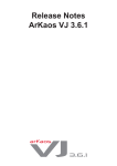
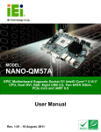
1
iVu4 & iVu9
Standalone Video Wall Controller
MODEL:
V
Video Wall Controller
Supports 2x2 and 3x3 LCD Panel Array
User Manual
U.K Head Office & Sales Center
Electronic Modular Solutions Ltd.
Kendal House, 20 Blaby Rd., S. Wigston, Leics., LE18 4SB, England
Tel: +44 (0)116 2775730, Fax: +44 (0)116 2774973
email: [email protected]
Web: http://www.ems-imaging.com
Rev. 1.00 October, 2008
Page i
iVu4/9 Standalone Video Wall Controller
Revision
Date
Version
Changes
October, 2008
1.00
Initial release
Page ii
iVu4/9 Standalone Video Wall Controller
Copyright
COPYRIGHT NOTICE
The information in this document is subject to change without prior notice in order to
improve reliability, design and function and does not represent a commitment on the part
of the manufacturer.
In no event will the manufacturer be liable for direct, indirect, special, incidental, or
consequential damages arising out of the use or inability to use the product or
documentation, even if advised of the possibility of such damages.
This document contains proprietary information protected by copyright. All rights are
reserved. No part of this manual may be reproduced by any mechanical, electronic, or
other means in any form without prior written permission of the manufacturer.
TRADEMARKS
All registered trademarks and product names mentioned herein are used for identification
purposes only and may be trademarks and/or registered trademarks of their respective
owners.
Page iii
iVu4/9 Standalone Video Wall Controller
Manual Conventions
WARNING!
Warnings appear where overlooked details may cause damage to the equipment or result
in personal injury. Warnings should be taken seriously. Warnings are easy to recognize.
The word “warning” is written as “WARNING,” both capitalized and bold and is followed by
text. The text is the warning message. A warning message is shown below:
WARNING:
This is an example of a warning message. Failure to adhere to warning
messages may result in permanent damage to the iVu4/9 or
personal injury to the user. Please take warning messages seriously.
CAUTION!
Cautionary messages should also be heeded to help reduce the chance of losing data or
damaging the iVu4/9. Cautions are easy to recognize. The word “caution” is
written as “CAUTION,” both capitalized and bold and is followed. The text is the cautionary
message. A caution message is shown below:
CAUTION:
This is an example of a caution message. Failure to adhere to cautions
messages may result in permanent damage to the iVu4/9.
Please take caution messages seriously.
Page iv
iVu4/9 Standalone Video Wall Controller
NOTE:
These messages inform the reader of essential but non-critical information. These
messages should be read carefully as any directions or instructions contained therein can
help avoid making mistakes. Notes are easy to recognize. The word “note” is written as
“NOTE,” both capitalized and bold and is followed by text. The text is the cautionary
message. A note message is shown below:
NOTE:
This is an example of a note message. Notes should always be read.
Notes contain critical information about the iVu4/9. Please take note
messages seriously.
Page v
iVu4/9 Standalone Video Wall Controller
Packing List
NOTE:
If any of the components listed in the checklist below are missing,
please do not proceed with the installation. Contact the EMS reseller or
vendor you purchased the iVu4/9 from or contact an EMS
sales representative directly. To contact an EMS sales representative,
please send an email to [email protected]
.
The items listed below should all be included in the iVu4/9 package.
1 x iVu4/9
1 x Power cord
1 x Power adapter
1 x Remote control
1 x RS-232 cable
1 x DVI-I dual link cable
1 x User manual and utilities CD
2 x Mount bracket
1 x Screw set
Images of the above items are shown in Chapter 3.
Page vi
iVu4/9 Standalone Video Wall Controller
Table of Contents
1 INTRODUCTION.......................................................................................................... 1
1.1 INTRODUCTION .......................................................................................................... 2
1.2 BENEFITS ................................................................................................................... 2
1.3 FEATURES .................................................................................................................. 2
1.4 EXTERNAL INTERFACES, SWITCHES AND LEDS ......................................................... 3
1.5 TECHNICAL SPECIFICATIONS ...................................................................................... 5
2 SYSTEM OVERVIEW.................................................................................................. 7
2.1 DIMENSIONS .............................................................................................................. 8
2.1.1 iVu4 Dimensions................................................................................................ 8
2.1.2 iVu9 Dimensions................................................................................................ 9
2.2 EXTERNAL OVERVIEW ............................................................................................. 10
2.2.1 Front Panel ...................................................................................................... 10
2.2.2 Rear Panel ........................................................................................................11
2.2.2.1 DVI Connector.......................................................................................... 12
2.2.2.2 Serial Port.................................................................................................. 13
3 UNPACKING LIST ..................................................................................................... 15
3.1 ANTI-STATIC PRECAUTIONS ...................................................................................... 16
3.2 UNPACKING PRECAUTIONS....................................................................................... 16
3.3 PACKING LIST .......................................................................................................... 17
3.4 OPTIONAL ITEMS ...................................................................................................... 18
4 INSTALLATION ......................................................................................................... 19
4.1 INSTALLATION OVERVIEW ........................................................................................ 20
4.1.1 Four Panel Overview....................................................................................... 20
4.1.2 16 Panel Overview........................................................................................... 21
4.2 INSTALLATION STEPS ............................................................................................... 22
4.3 INSTALL LCD PANELS.............................................................................................. 22
4.4 MOUNTING............................................................................................................... 22
4.5 CONNECT CABLES.................................................................................................... 23
Page vii
iVu4/9 Standalone Video Wall Controller
4.5.1 Connect the Video Source and iVu4/9 ............................................................. 24
4.5.2 Connect the RS-232 Cable to the iVu4/9 (Optional) ....................................... 25
4.5.3 Connect the iVu4/9 to the Power Supply ......................................................... 26
4.6 RESOLUTION AND DISPLAY MODE ........................................................................... 27
4.7 BEZEL COMPENSATION ............................................................................................ 27
5 OSD FUNCTIONS....................................................................................................... 29
5.1 SMARTOSD.............................................................................................................. 30
5.1.1 Pre-installation Notice ..................................................................................... 30
5.1.2 Installing the smartOSD .................................................................................. 30
5.1.3 Using the smartOSD ........................................................................................ 35
5.1.3.1 Control Panel ............................................................................................ 36
5.1.3.2 Read OSD ................................................................................................. 38
5.1.3.3 Power Control ........................................................................................... 39
5.1.3.4 PC Setting ................................................................................................. 40
5.1.3.5 About Page ................................................................................................ 41
5.2 USING THE OSD....................................................................................................... 42
5.2.1 OSD Buttons..................................................................................................... 42
5.2.2 OSD Lock ......................................................................................................... 42
5.2.3 OSD Menu........................................................................................................ 43
5.2.3.1 Bezel Control ............................................................................................ 44
5.2.3.2 Input Resolution........................................................................................ 45
5.2.3.3 Output Resolution ..................................................................................... 46
5.2.3.4 Synchronization ........................................................................................ 47
5.2.3.5 Hardware Information............................................................................... 48
5.2.3.6 Model Information .................................................................................... 49
5.2.4 Remote Control ................................................................................................ 49
6 TROUBLESHOOTING AND MAINTENANCE ..................................................... 51
6.1 ANTI-STATIC PRECAUTIONS ...................................................................................... 52
6.2 MAINTENANCE OVERVIEW....................................................................................... 53
6.3 TROUBLESHOOTING ................................................................................................. 53
6.3.1 No Image on One Monitor ............................................................................... 53
6.3.1.1 Check Monitor Power ............................................................................... 53
6.3.1.2 Check Panel Video Connection................................................................. 53
Page viii
iVu4/9 Standalone Video Wall Controller
6.3.2 No Image Two or Three Monitors .................................................................... 54
6.3.3 No Image on Any Monitor................................................................................ 54
6.3.3.1 Check Video Box Power ........................................................................... 54
6.3.3.2 Check Source Video Connection .............................................................. 54
A RS-232 SETUP............................................................................................................. 55
A.1 SETUP...................................................................................................................... 56
A.2 PACKET FORMAT ..................................................................................................... 56
A.3 COMMAND REFERENCE ........................................................................................... 57
A.3.1 Get Display Status ........................................................................................... 58
A.3.2 Get Factory Defaults ....................................................................................... 59
A.3.3 Set Mask Control ............................................................................................. 60
A.3.4 Set Display Mode............................................................................................. 61
A.3.5 Set Display Resolution..................................................................................... 61
A.3.6 Set Input Source............................................................................................... 62
A.3.7 Set Power Control ........................................................................................... 62
A.3.8 Set to Default ................................................................................................... 63
A.3.9 Set OSD Mode ................................................................................................. 63
B TERMINOLOGY........................................................................................................ 64
C HAZARDOUS MATERIALS DISCLOSURE ......................................................... 66
C.1 HAZARDOUS MATERIALS DISCLOSURE TABLE FOR IPB PRODUCTS CERTIFIED AS
ROHS COMPLIANT UNDER 2002/95/EC WITHOUT MERCURY ....................................... 67
Page ix
iVu4/9 Standalone Video Wall Controller
List of Figures
Figure 1-1: iVu4/9 ...........................................................................................................................2
Figure 1-2: iVu4 Overview (Front View) .......................................................................................3
Figure 1-3: iVu9 Overview (Front View) .......................................................................................4
Figure 1-4: Overview (Rear View)..................................................................................................4
Figure 1-5: Overview (Rear View)..................................................................................................5
Figure 2-1: iVu4 Video Box Dimensions ......................................................................................8
Figure 2-2: iVu9 Video Box Dimensions ......................................................................................9
Figure 2-3: iVu4 Front Panel .......................................................................................................10
Figure 2-4: iVu9 Front Panel .......................................................................................................11
Figure 2-5: iVu4 Rear Panel ........................................................................................................12
Figure 2-6: iVu9 Rear Panel ........................................................................................................12
Figure 2-7: COM1 Pinout Locations............................................................................................14
Figure 4-1: Four Panel Setup.......................................................................................................20
Figure 4-2: 9 Panel Setup.............................................................................................................21
Figure 4-3: Mounting Brackets....................................................................................................23
Figure 4-4: Cable Connections....................................................................................................24
Figure 4-5: Video Source .............................................................................................................25
Figure 4-6: iVu4/9 Video Input.....................................................................................................25
Figure 4-7: Serial Device Connector...........................................................................................26
Figure 4-8: Display Mode .............................................................................................................27
Figure 4-9: Mask Calculation.......................................................................................................28
Figure 5-1: smartOSD Language Selection ...............................................................................31
Figure 5-2: smartOSD Welcome Screen.....................................................................................31
Figure 5-3: smartOSD Installation Directory..............................................................................32
Figure 5-4: smartOSD Start Menu Folder ...................................................................................32
Figure 5-5: smartOSD Additional Tasks.....................................................................................33
Figure 5-6: smartOSD Ready to Install .......................................................................................33
Figure 5-7: smartOSD Installing..................................................................................................34
Figure 5-8: smartOSD Installation Complete .............................................................................34
Figure 5-9: smartOSD Control Panel ..........................................................................................36
Page x
iVu4/9 Standalone Video Wall Controller
Figure 5-10: smartOSD Read OSD ..............................................................................................38
Figure 5-11: smartOSD Power Control .......................................................................................39
Figure 5-12: smartOSD PC Setting .............................................................................................40
Figure 5-13: smartOSD About Page............................................................................................41
Figure 5-14: OSD Buttons............................................................................................................42
Figure 5-15: Bezel Control ...........................................................................................................44
Figure 5-16: Input Resolution......................................................................................................45
Figure 5-17: Display Menu ...........................................................................................................46
Figure 5-18: Synchronization ......................................................................................................47
Figure 5-19: Hardware Information .............................................................................................48
Figure 5-20: Input Select..............................................................................................................49
Figure 5-21: Remote Control .......................................................................................................50
Page xi
iVu4/9 Standalone Video Wall Controller
List of Tables
Table 1-1: Technical Specifications..............................................................................................6
Table 2-1: DVI Connector Pinouts...............................................................................................13
Table 2-2: COM1 Pinouts .............................................................................................................13
Table 3-1: Package List Contents ...............................................................................................18
Table 3-2: Optional Items.............................................................................................................18
Table 4-1: Input and Output Resolution .....................................................................................27
Table 5-1: smartOSD Menu Structure.........................................................................................35
Table 5-2: OSD Menu Structure...................................................................................................43
Table 6-1: RS-232 Setup...............................................................................................................56
Table 6-2: n-Byte Data Output Format........................................................................................56
Table 6-3: Get Display Status ......................................................................................................58
Table 6-4: Get Factory Defaults...................................................................................................59
Table 6-5: Set Mask Control ........................................................................................................60
Table 6-6: Set Display Mode ........................................................................................................61
Table 6-7: Set Display Resolution...............................................................................................61
Table 6-8: Set Input Source .........................................................................................................62
Table 6-9: Set Power Control.......................................................................................................62
Table 6-10: Set to Default.............................................................................................................63
Table 6-11: Set OSD Mode ...........................................................................................................63
Page xii
iVu4/9 Standalone Video Wall Controller
Chapter
1
1 Introduction
Page 1
iVu4/9 Standalone Video Wall Controller
1.1 Introduction
Figure 1-1: iVu4/9 Standalone
The EMS iVu4/9 video wall controller box is for displaying a single video input on an
array of monitors, implementing a large display without the inherent high costs of a single
large monitor. The EMS iVu4/9 is for large displays where high definition video
output is also essential. The video wall controller accepts a single DVI input. The
EMS iVu4/9 requires a high-resolution digital video input signal, which is split directly
over the panels in the array, with no image scaling or adjustment, ensuring maximum
image accuracy. The EMS iVu4/9 video controller box can be controlled remotely
using the included remote control or from a computer with an RS-232 serial port.
1.2 Benefits
The benefits of the iVu4/9 include:
Accurate, high-definition image
Silent operation
Simple setup
Cheaply implements a large display
1.3 Features
The features of the iVu4/9 include:
DVI video input
Four/nine DVI video outputs
Support for up to 1920 x 1200 output resolution
Multiple video output combinations including full video wall mode, clone mode
and vertical replication mode
Bezel control compensates for gaps between monitors
Page 2
iVu4/9 Standalone Video Wall Controller
1.4 External Interfaces, Switches and LEDs
External interfaces, switches and LEDs are accessed through the iVu4/9 video
wall controller chassis include:
4 x DVI outputs (9 for iVu9)
1 x DVI input
4 x DVI output LED indicators (9 for iVu9)
1 x OSD menu keypad
1 x Power input
1 x Power LED indicator
1 x RS-232 serial communications port
1 x Sync in
1 x Sync out
1 x Video in LED indicator
Figure 1-2 and Figure 1-3 show the buttons and LED indicators on the front panel.
Figure 1-2: iVu4 Overview (Front View)
Page 3
iVu4/9 Standalone Video Wall Controller
Figure 1-3: iVu9 Overview (Front View)
Figure 1-4 and Figure 1-5 show the external peripheral interface connectors on the rear
panel.
Figure 1-4: Overview (Rear View)
Page 4
iVu4/9 Standalone Video Wall Controller
Figure 1-5: Overview (Rear View)
1.5 Technical Specifications
iVu4/9 video box features are listed in Table 1-1. See Chapter 2 for details.
Specification
Detail
Model Name
iVu4/9
1. Multiple viewing modes
Main Features
2. Software OSD
3. Remote control
4. Bezel masking
Inputs
Outputs
Dimensions (H x W x D)
Cooling
DVI
iVu4 – 4 x DVI
iVu9 – 9 x DVI
iVu4 – 47 mm x 230 mm x 178 mm
iVu9 – 47 mm x 295 mm x 188 mm
Fanless
1920x1080, 1920x1200, 2048x768, 2560x1024,
Input Resolution
3840x1080, 3840x1200, 2048x1536, 2560x2048,
3840x2160, 3840x2400
Output Resolution
1024x768, 1280x1024, 1920x1080, 1920x1200
Power Adapter Input
90 VAC to 264 VAC / 47 Hz to 63 Hz
Page 5
iVu4/9 Standalone Video Wall Controller
Specification
Detail
Power Adapter Output
12 V DC
Safety and Emission
CCC, CE, FCC
Temperature
0ºC – 40ºC
Power Consumption
iVu4 – 10 W
iVu9 – 17 W
Table 1-1: Technical Specifications
Page 6
iVu4/9 Standalone Video Wall Controller
Chapter
2
2 System Overview
Page 7
iVu4/9 Standalone Video Wall Controller
2.1 Dimensions
The dimensions of the iVu4/9 are listed in the sections below.
2.1.1 iVu4 Dimensions
Height:
47 mm
Width:
230 mm
Depth:
178 mm
Figure 2-1: iVu4 Video Box Dimensions
Page 8
iVu4/9 Standalone Video Wall Controller
2.1.2 iVu9 Dimensions
Height:
47 mm
Width:
295 mm
Depth:
188 mm
Figure 2-2: iVu9 Video Box Dimensions
Page 9
iVu4/9 Standalone Video Wall Controller
2.2 External Overview
This section gives and overview of the connectors, switches and indicators on the
iVu4/9.
2.2.1 Front Panel
The front panel has the following buttons and indicators (shown in Figure 2-3 and
Figure 2-4 below):
Power indicator LED
Video output LEDs
Video input LED
OSD menu keypad
Figure 2-3: iVu4 Front Panel
Page 10
iVu4/9 Standalone Video Wall Controller
Figure 2-4: iVu9 Front Panel
2.2.2 Rear Panel
The rear panel has the following connectors, switches and indicators (shown in Figure 2-5
and Figure 2-6 below):
4 x DVI video outputs (9 on the iVu9)
1 x DVI video input
1 x Power input
1 x Power switch
1 x RS-232 serial communications port
1x Sync in
1 x Sync out
Page 11
iVu4/9 Standalone Video Wall Controller
Figure 2-5: iVu4 Rear Panel
Figure 2-6: iVu9 Rear Panel
2.2.2.1 DVI Connector
CN Label:
DVI1
CN Type:
DVI connector
CN Location
See Figure 2-5
CN Pinouts:
See Table 2-1
The 24-pin Digital Visual Interface (DVI) connector connects to high-speed,
high-resolution digital displays. The DVI-I connector supports both digital and analog
signals.
Page 12
iVu4/9 Standalone Video Wall Controller
PIN
Signal Name
Pin #
Signal Name
Pin #
Signal Name
1
TMDS Data2-
9
TMDS Data1-
17
TMDS Data0-
2
TMDS Data2+
10
TMDS Data1+
18
TMDS Data0+
3
GND
11
GND
19
GND
4
N/C
12
NC
20
NC
5
N/C
13
NC
21
NC
6
DDC Clock [SCL]
14
PVDD1
22
GND
7
DDC Data [SDA]
15
GND
23
TMDS Clock +
8
Analog vertical sync
16
GND
24
TMDS Clock -
C1
Analog Red
C2
Analog Green
C3
Analog Blue
C4
Analog Horizontal Sync
C5
Analog GND
Table 2-1: DVI Connector Pinouts
2.2.2.2 Serial Port
CN Label:
COM1
CN Type:
RS-232 serial connector
CN Location:
See Figure 2-5
CN Pinouts:
See Table 2-2 and Figure 2-7
The RS-232 serial connector provides serial connections in RS-232 mode.
PIN
DESCRIPTION
PIN
DESCRIPTION
1
DCD1
2
DSR1
3
RX1
4
RTS1
5
TX1
6
CTS1
7
DTR1
8
RI1
9
GND
Table 2-2: COM1 Pinouts
Page 13
iVu4/9 Standalone Wall Controller
Figure 2-7: COM1 Pinout Locations
Page 14
iVu4/9 Standalone Video Wall Controller
Chapter
3
3 Unpacking List
Page 15
iVu4/9 Standalone Video Wall Controller
3.1 Anti-static Precautions
WARNING:
Failure to take ESD precautions during the installation of the
iVu4/9
may
result
in
permanent
damage
to
the
iVu4/9 and severe injury to the user.
Electrostatic discharge (ESD) can cause serious damage to electronic components,
including the iVu4/9. Dry climates are especially susceptible to ESD. It is
therefore critical that whenever the iVu4/9, or any other electrical component is
handled, the following anti-static precautions are strictly adhered to.
Wear an anti-static wristband: - Wearing a simple anti-static wristband can
help to prevent ESD from damaging the board.
Self-grounding:- Before handling the board touch any grounded conducting
material. During the time the board is handled, frequently touch any
conducting materials that are connected to the ground.
Use an anti-static pad: - When configuring the iVu4/9, place it on
an antic-static pad. This reduces the possibility of ESD damaging the
iVu4/9.
Only handle the edges of the PCB:- When handling the PCB, hold the PCB
by the edges.
3.2 Unpacking Precautions
When the iVu4/9 is unpacked, please do the following:
Follow the anti-static precautions outlined in Section 3.1.
Make sure the packing box is facing upwards so the iVu4/9 does
not fall out of the box.
Make sure all the components shown in Section 3.3 are present.
Page 16
iVu4/9 Standalone Video Wall Controller
3.3 Packing List
NOTE:
If some of the components listed in the checklist below are missing,
please do not proceed with the installation. Contact the EMS reseller or
vendor that sold the iVu4 / 9 from or contact an EMS sales
representative directly. To contact an EMS sales representative, please
send an email to [email protected]
The iVu4/9 is shipped with the following components:
No.
Description
1
iVu4/9
1
Power cord
1
Power adapter
1
Remote control
1
Mounting brackets
1
Screw kit
1
User manual and utilities CD
Image
Page 17
iVu4/9 Standalone Video Wall Controller
No.
Description
2
RS-232 cable
1
DVI cable
Image
Table 3-1: Package List Contents
3.4 Optional Items
The following optional items are available for the iVu4/9:
Description
DVI cable
Table 3-2: Optional Items
Page 18
Image
iVu4/9 Standalone Video Wall Controller
Chapter
4
4 Installation
Page 19
iVu4/9 Standalone Video Wall Controller
4.1 Installation Overview
The iVu4 supports a 4-panel setup and the iVu9 supports a 9-panel
setup.
4.1.1 Four Panel Overview
The implementation of a 4-panel array is shown in Figure 4-1 below.
Figure 4-1: Four Panel Setup
Page 20
iVu4/9 Standalone Video Wall Controller
4.1.2 16 Panel Overview
The implementation of a 9-panel array is shown in Figure 4-2 below.
Figure 4-2: 9 Panel Setup
Page 21
iVu4/9 Standalone Video Wall Controller
4.2 Installation Steps
To install the iVu4/9 please follow the installation steps below:
Step 1: Install the LCD panels.
Step 2: Mount the iVu4/9.
Step 3: Connect DVI cables, video input cable, RS-232 cable and power adapter to the
iVu4/9.
Step 4: Adjust the screen resolution output settings.
Step 5: Adjust the iVu4/9 bezel settings to align the images.Step0:
4.3 Install LCD Panels
The LCD panels are installed as a square array, with two rows and two columns for the
iVu4 and three rows and three columns for the iVu9.
Recommended installation procedures are to
Use all identical monitors
Minimize gaps between panels for the best image
Maintain consistent horizontal gaps between monitors
Maintain consistent vertical gaps between monitors
4.4 Mounting
The iVu4/9 must be placed on a table, desk or other firm surface. Optionally,
the iVu4/9 can be mounted using the included mounting brackets. The
installation location must be:
Out of direct sunlight
Without anything on top of it
On a firm surface
Away from moisture and liquids
Page 22
iVu4/9 Standalone Video Wall Controller
Figure 4-3: Mounting Brackets
4.5 Connect Cables
The cables that need to be attached to the iVu4 are listed below and their
connections are shown in Figure 4-4 (connections for the iVu9 are similar):
Video input cable – from a DVI video source
Video output cables – attached to the LCD panels or another
iVu4/9. Make sure the cables are connected to the correct
monitors as shown in Figure 4-4.
Power cable – from the power adapter
RS-232 cable (optional) – connected to a computer with smartOSD software
installed
Page 23
iVu4/9 Standalone Video Wall Controller
Figure 4-4: Cable Connections
4.5.1 Connect the Video Source and iVu4/9
Connect the video source to the iVu4/9. If the video source is a computer with
the smartOSD software installed, that computer can be used to adjust the monitor settings
without using the OSD.
The video source connects directly to the iVu4/9 through a DVI cable.
To connect the video source to the iVu4/9, follow the steps below.
Page 24
iVu4/9 Standalone Video Wall Controller
Step 1: Attach the DVI cable to the video source.
Figure 4-5: Video Source
Step 2: Attach the video cable to the iVu4/9.Step 0:
Figure 4-6: iVu4/9 Video Input
4.5.2 Connect the RS-232 Cable to the iVu4/9 (Optional)
The iVu4/9 has a male DB-9 connector on the rear panel. The RS-232 cable
connects to a computer that has the smartOSD software installed. This enables the
computer to control the screen setup. This computer does not need to be the video
source. If the video source is from a PC the image screen setup can be controlled through
Page 25
iVu4/9 Standalone Video Wall Controller
the DVI or VGA cable. Follow the steps below to connect a serial device to the
iVu4/9.
Step 1: Locate the DB-9 connector. The location of the DB-9 connector is shown in
Chapter 2.
Step 2: Insert the serial connector. Insert the DB-9 connector of a serial device into
the DB-9 connector on the external peripheral interface. See Figure 4-7.
Figure 4-7: Serial Device Connector
Step 3: Secure the connector. Secure the serial device connector to the external
interface by tightening the two retention screws on either side of the connector.Step0:
4.5.3 Connect the iVu4/9 to the Power Supply
Connect the included PSU into an AC power supply then connect the PSU to the
iVu4/9. The figure below shows the typical setup. There is no power switch,
and the iVu4/9 turns on as soon as it is connected to the PSU.
Page 26
iVu4/9 Standalone Video Wall Controller
4.6 Resolution and Display Mode
The iVu4/9 display mode is automatically selected according to the input
resolution. The display modes are shown in Figure 4-8 and the input resolution settings
are shown in Table 4-1.
Figure 4-8: Display Mode
Input Resolution
Mode
Video Output Resolution
1920x1080@60 Hz
Clone – same image
1920x1080@50 Hz
1920x1200@60 Hz
on all monitors
1920x1200@50 Hz
2048x768@60 Hz
Split – same image
1024x768@60 Hz
2560x1024@60 Hz
shows on each row or
1280x1024@60 Hz
3840x1080@40 Hz
monitors
1920x1080@50 Hz
1920x1200@50 Hz
3840x1200@40 Hz
2048x1536@58 Hz
Video wall – image
1024x768@60 Hz
2560x2048@50 Hz
split over all monitors
1280x1024@60 Hz
3840x2160@24 Hz
1920x1080@50 Hz
3840x2400@25 Hz
1920x1200@50 Hz
Table 4-1: Input and Output Resolution
4.7 Bezel Compensation
The bezel compensation setting compensates for the gaps between monitors in the video
wall array. The bezel compensation sizes the image slightly larger than the visible screen
Page 27
iVu4/9 Standalone Video Wall Controller
to make the images on adjacent monitors line-up correctly. The bezel settings can be set
using the smartOSD (Section 5.1) or OSD menu (Section 5.2).
To calculate the appropriate mask value, use the formula shown in Figure 4-9 below:
Figure 4-9: Mask Calculation
Page 28
iVu4/9 Standalone Video Wall Controller
Chapter
5
5 OSD Functions
Page 29
iVu4/9 Standalone Video Wall Controller
5.1 smartOSD
EMS smartOSD is a proprietary On-Screen-Display (OSD) software solution from EMS that
enables easy, remote monitor setting adjustments in a Windows environment. EMS
smartOSD delivers excellent performance and provides more flexibility than the typical
OSD hardware solutions when adjusting a monitor. smartOSD also allows the screen
output screen resolution and mask size to be adjusted over a DVI cable.
5.1.1 Pre-installation Notice
Before installing smartOSD software, please make sure one of the following operating
systems is installed:
Windows 95
Windows NT 4.0
Windows 98
Windows 2000
Windows 2003
Windows XP
Windows Vista
5.1.2 Installing the smartOSD
To install the software, please follow the steps below:
Step 1: Follow the instructions from the interactive installer to install the EMS smartOSD
on the system.
Step 2: Insert the installation disk that came with the system and open the installation
file.
Page 30
iVu4/9 Standalone Video Wall Controller
Step 3: The language selection window appears (Figure 5-1).
Figure 5-1: smartOSD Language Selection
Step 4: Select the preferred language then click OK.
Step 5: The welcome screen shown below appears (Figure 5-2).
Figure 5-2: smartOSD Welcome Screen
Step 6: Click NEXT to continue.
Page 31
iVu4/9 Standalone Video Wall Controller
Step 7: The Select Destination Folder window appears (Figure 5-3).
Figure 5-3: smartOSD Installation Directory
Step 8: Change the installation directory if necessary. Click NEXT to continue.
Step 9: The Select Start Menu Folder option window appears (Figure 5-4).
Figure 5-4: smartOSD Start Menu Folder
Step 10: Choose a new name or folder for the Start Menu entry if necessary. Click NEXT
to continue.
Page 32
iVu4/9 Standalone Video Wall Controller
Step 11: The Additional Tasks window appears (Figure 5-5).
Figure 5-5: smartOSD Additional Tasks
Step 12: Check the extra items that should be added (optional). Click NEXT to continue.
Step 13: The Ready to Install windows appears (Figure 5-6).
Figure 5-6: smartOSD Ready to Install
Step 14: Confirm the installation by clicking INSTALL in the screen above.
Page 33
iVu4/9 Standalone Video Wall Controller
Step 15: The Installation Progress window appears, showing the progress of the
software installation (Figure 5-7).
Figure 5-7: smartOSD Installing
Step 16: The Completing the iVu Setup Wizard window appears (Figure 5-8)
Figure 5-8: smartOSD Installation Complete
Page 34
iVu4/9 Standalone Video Wall Controller
Step 17: Click FINISH to close the installation wizard. Step0:
5.1.3 Using the smartOSD
The table below shows the smartOSD menu structure (Table 5-1).
Menu
Options
Interface
Interface Selection
Display
Display Resolution
Display Mode
Mask Setting
Setting
Digital I/O Test
Input Source
Power
Factory Reset
OSD Lock
OSD Rotation
About
Company Contact Details
Table 5-1: smartOSD Menu Structure
Page 35
iVu4/9 Standalone Video Wall Controller
5.1.3.1 Control Panel
The control panel page presents all the adjustable settings for the iVu4/9.
Figure 5-9: smartOSD Control Panel
Bezel Control
The Bezel Control options allow the images to be adjusted to compensate for the gaps
between monitors in the video array.
Off
The images are shown without any adjustments
On
The value of X and the value of Y can be adjusted to compensate
for gaps between monitors (for single video box)
ML
The left side is fixed and the right side changes when
adjustments are made (for left side video box in a two video box
setup)
Page 36
iVu4/9 Standalone Video Wall Controller
MR
The right side is fixed and the left side changes when
adjustments are made (for right side video box in a two video box
setup)
MUL
The upper left corner is fixed and the lower right corner position
changes when adjustments are made (for top left video box in a
four video box setup)
MUR
The upper right corner is fixed and the lower left corner position
changes when adjustments are made (for top right video box in a
four video box setup)
MLL
The lower left corner is fixed and the upper right corner position
changes when adjustments are made (for lower left video box in
a four video box setup)
MLR
The lower right corner is fixed and the upper left corner position
changes when adjustments are made (for lower right video box in
a four video box setup)
Value of X
The Value of X sets the horizontal bezel compensation. Use the formula in Figure 4-9 to
calculate the correct setting.
Value of Y
The Value of Y sets the horizontal bezel compensation. Use the formula in Figure 4-9 to
calculate the correct setting.
Display Mode
The Display Mode option sets the video output resolution.
XGA
Output resolution is set to 1024 x 768
SXGA
Output resolution is set to 1280 x 1024
HDTV
Output resolution is set to 1920 x 1080
WUXGA
Output resolution is set to 1920 x 1200
Page 37
iVu4/9 Standalone Video Wall Controller
Sync
The Sync option sets the syncing between multiple video boxes.
On
Video boxes are set to synchronize with each other
Off
Video boxes are not set to synchronize with each other
5.1.3.2 Read OSD
The Read OSD menu displays the settings of the video wall box.
Figure 5-10: smartOSD Read OSD
Page 38
iVu4/9 Standalone Video Wall Controller
5.1.3.3 Power Control
Figure 5-11: smartOSD Power Control
Power Control
The Power Control option turns the iVu4/9 on and off.
On
Turns on the video box
Off
Turns off the video box
Page 39
iVu4/9 Standalone Video Wall Controller
5.1.3.4 PC Setting
The PC Setting page sets the command port to use for data communication between the
video box and the computer.
Figure 5-12: smartOSD PC Setting
COM Port
The COM Port sets which serial port to use for data communication with the video box.
The available serial ports depend on the system.
Identify
The Identify button shows a red square for each full image in the array.
Page 40
Clone Mode
Four red squares are displayed
Split Mode
Two red squares are displayed
Video Wall
One red square is displayed
iVu4/9 Standalone Video Wall Controller
5.1.3.5 About Page
The About Page shows some general information about the smartOSD.
Figure 5-13: smartOSD About Page
Page 41
iVu4/9 Standalone Video Wall Controller
5.2 Using the OSD
The OSD menu functions are described below.
5.2.1 OSD Buttons
There are several on-screen-display (OSD) control buttons oriented either vertically on the
right side of the monitor front panel or on the bottom of the monitor front panel.
Figure 5-14 shows a typical arrangement of OSD controls.
43
Figure 5-14: OSD Buttons
Menu/Enter. Enters the OSD, selects items and sets the new values entered.
Left. Moves the selection left.
Right. Moves the selection right.
Up. Moves the selection up.
Down. Moves the selection down.
Auto/Exit. Exits from any menu.
5.2.2 OSD Lock
The OSD front panel buttons can be locked using the OSD lock function. To turn the OSD
lock on and off, follow the steps below. (The OSD can also be locked using the
smartOSD).
Step 1: Push the “Right” and “Auto/Exit” buttons simultaneously for a few seconds.
Step 2: The OSD display shows the current status as locked or unlocked. Step0:
Page 42
iVu4/9 Standalone Video Wall Controller
5.2.3 OSD Menu
The subsections below cover the layout and use of the OSD. The table below shows the
OSD menu structure.
Menu
Options
Description
Bezel control
BC
Turns bezel on and off
X
Sets horizontal bezel value
Y
Sets vertical bezel value
INX
Displays horizontal input resolution
INY
Displays vertical input resolution
MD
Displays the video display mode
DS
Displays output setting
H
Displays output horizontal resolution
V
Displays output vertical resolution
SYN
Turns synchronization on and off
PWR
Turns off the video box
FP
Displays the video chip revision number
CP
Displays the video chip revision number
FW
Displays the firmware revision number
Name
Displays the model name
SN
Displays the serial number
Input resolution
Output resolution
Synchronization
Input selection
Model information
Table 5-2: OSD Menu Structure
Page 43
iVu4/9 Standalone Video Wall Controller
5.2.3.1 Bezel Control
The bezel control options are shown in Figure 5-15 and described below.
43
Figure 5-15: Bezel Control
BC
BC enables and disables bezel control. Bezel control adjusts the onscreen image to
compensate for the gaps between monitors in the video wall array.
Off
On
DEFAULT
Onscreen image is not adjusted
Onscreen image is adjusted
X
X sets how much the horizontal resolution of the image is adjusted to compensate for the
gaps between the monitors. Use the formula in Figure 4-9 to calculate the value of X.
Y
Y sets how much the horizontal resolution of the image is adjusted to compensate for the
gaps between the monitors. Use the formula in Figure 4-9 to calculate the value of Y.
Page 44
iVu4/9 Standalone Video Wall Controller
5.2.3.2 Input Resolution
The input resolution menu displays the input resolution and the automatically selected
video mode.
Figure 5-16: Input Resolution
INX
Displays the horizontal resolution of the video input signal. The following values are
permissible.
1920
2048
2560
3840
INY
Displays the vertical resolution of the video input signal. The following values are
permissible.
768
1024
1080
1200
1536
2048
2400
Page 45
iVu4/9 Standalone Video Wall Controller
MD
Displays the automatically selected video display mode.
1x1
The full image is displayed on all the monitors.
2x1
The full image is displayed on each row of the video wall array
2x2
The full image is displayed across the entire array with each monitor
showing a portion of the full image
5.2.3.3 Output Resolution
The output resolution menu displays the resolution of the video output.
Figure 5-17: Display Menu
DS
DS displays the name of the output resolution. Permissible values are:
XGA
SXGA
HDTV
WUXGA
H
H displays the horizontal resolution of the video output. Permissible values are:
1024
Page 46
iVu4/9 Standalone Video Wall Controller
1280
1920
V
V displays the vertical resolution of the video output. Permissible values are:
768
1024
1080
1200
5.2.3.4 Synchronization
The Synchronization menu sets the synchronization between video wall boxes in a
multiple video box setup.
Figure 5-18: Synchronization
SYN
Turns synchronization on and off.
On
The video boxes are connected with a cable and the displayed images
are synchronized.
Off
The video boxes display output in the default fashion.
Page 47
iVu4/9 Standalone Video Wall Controller
PWR
Turns the video box on and off
On
The video box is powered on
Off
The video box is powered off
5.2.3.5 Hardware Information
The Hardware Information menu shows the hardware information of the video box.
Figure 5-19: Hardware Information
FP
FP displays the firmware version of the onboard chip.
CP
CP displays the firmware version of the onboard chip.
FW
FW shows the version number of the video box firmware.
Page 48
iVu4/9 Standalone Video Wall Controller
5.2.3.6 Model Information
The Model Information menu shows the model name and the serial number of the video
box.
Figure 5-20: Input Select
Model Name
The first line displays the model name of the current video box.
SN
SN displays the serial number of the video box.
5.2.4 Remote Control
The iVu4/9 comes with a remote control for easy configuration of OSD settings.
Figure 5-21 shows the remote control and its function keys.
43
Page 49
iVu4/9 Standalone Video Wall Controller
Figure 5-21: Remote Control
Power. Turns the video box on and off.
Menu. Enters the OSD, selects items and sets the new values entered.
Left. Moves the selection left.
Right. Moves the selection right.
Up. Moves the selection up.
Down. Moves the selection down.
Auto/Enter. Exits from any menu.
Page 50
iVu4/9 Standalone Video Wall Controller
Chapter
6
6 Troubleshooting and
Maintenance
Page 51
iVu4/9 Standalone Video Wall Controller
WARNING:
Take Anti-Static precautions whenever maintenance is being carried
out on the embedded system components. Failure to take anti-static
precautions can cause permanent embedded system damage.
6.1 Anti-static Precautions
WARNING:
Failure to take ESD precautions during the installation of the
iVu4/9
may
result
in
permanent
damage
to
the
iVu4/9 and severe injury to the user.
Electrostatic discharge (ESD) can cause serious damage to electronic components,
including the iVu4/9. Dry climates are especially susceptible to ESD. It is
therefore critical that whenever the iVu4/9, or any other electrical component is
handled, the following anti-static precautions are strictly adhered to.
Wear an anti-static wristband: - Wearing a simple anti-static wristband can
help to prevent ESD from damaging the board.
Self-grounding: - Before handling the board or opening the embedded
system, touch any grounded conducting material. During the time the board is
handled, frequently touch any conducting materials that are connected to the
ground.
Use an anti-static pad: - When configuring the iVu4/9, place it on
an antic-static pad. This reduces the possibility of ESD damaging
the iVu4/9.
Only handle the edges of the PCB: - When handling the PCB, hold the PCB
by the edges.
Page 52
iVu4/9 Standalone Video Wall Controller
6.2 Maintenance Overview
NOTE:
There are no user-serviceable parts inside. Make sure to carefully
follow all the instructions in this section to diagnose any problems. If
the problem persists, email [email protected] for help from an EMS
sales representative
To preserve the working integrity of the iVu4/9 embedded system, the
embedded system must be properly maintained. If embedded system components need
replacement, the proper maintenance procedures must be followed to ensure the
embedded system can continue to operate normally.
6.3 Troubleshooting
This section provides some simple troubleshooting suggestions.
6.3.1 No Image on One Monitor
If there is no image on one monitor, follow these steps to remedy the problem.
6.3.1.1 Check Monitor Power
Step 1: Check that the monitor is turned on.
Step 2: Check that the power source for the monitor is turned on.
Step 3: Check that the power source has the correct power rating (check panel
specifications for details).
Step 4: Make sure the LCD panel power cables are securely fastened to the monitor and
to the power source.Step0:
6.3.1.2 Check Panel Video Connection
Check to see that the video cable is fitted correctly.
Page 53
iVu4/9 Standalone Video Wall Controller
Step 1: Check that the monitor is connected to the iVu4/9.
Step 2: Securely attach the video cable to the panel and to the iVu4/9.
Step 3: Fasten the video cable at both ends and tighten the video cable screws.Step0:
6.3.2 No Image Two or Three Monitors
If there is no image on more than one of the panels, then repeat the steps in Section 6.3.1
for all of the monitors in the array.
6.3.3 No Image on Any Monitor
If no image displays on any monitors, repeat the steps in Section 6.3.1 for all the monitors
in the array, then try the following additional steps.
6.3.3.1 Check Video Box Power
Make sure that the video box is powered on.
Step 1: Check the power supply is connected to the power source.
Step 2: Check that the iVu4/9 is connected to the power supply.Step0:
6.3.3.2 Check Source Video Connection
Check to that the source video cable is securely connected to the iVu4/9.
Step 1: Securely attach the video cable from the video source to the iVu4/9.
Step 2: Fasten the video cable at both ends and tighten the video cable screws. Step 0:
Page 54
iVu4/9 Standalone Video Wall Controller
Appendix
A
A RS-232 Setup
Page 55
iVu4/9 Standalone Video Wall Controller
A.1 Setup
The serial port is used to remotely set and get the settings from the iVu4/9. The
serial port is used by user applications to change the settings of the iVu4/9
through a software interface. The serial port should be setup as indicated in Table 6-1
Description
Setting
Baud rate
115200
Parity
Non-parity
Data bit
8
Stop bit
1
Flow control
None
Table 6-1: RS-232 Setup
A.2 Packet Format
The generalized format of a single data packet on the RS-232 communications port is
shown in Table 6-2. The specific setup details for all the commands are shown in the next
section.
Byte
Function
[1]
The number of bytes in the signal
[2]
This byte indicates the command to perform
[3]-[n-1]*
These bytes contain the data needed for the command
[n]*
Checksum byte
Table 6-2: n-Byte Data Output Format
* n indicates the number of bytes (length) of the data packet. This value depends on the
command that is being used.
Page 56
iVu4/9 Standalone Video Wall Controller
A.3 Command Reference
This section details the commands that can be sent over the RS-232 communications port.
The following commands are detailed:
Get display status................................................................................... 58
Get factory defaults ................................................................................ 59
Set mask control .................................................................................... 60
Set display mode.................................................................................... 61
Set display resolution ............................................................................. 61
Set input source ..................................................................................... 62
Set power control ................................................................................... 62
Set to default .......................................................................................... 63
Set OSD mode ....................................................................................... 63
Page 57
iVu4/9 Standalone Video Wall Controller
A.3.1 Get Display Status
Byte
Value
[1]
0x08
[2]
0x03
[3]
Output resolution:
0 – 1024 x 768
1 – 1360 x 768
2 – 1280 x 1024
3 – 1400 x 1500
4 – 1680 x 1050
5 – 1600 x 1200
6 – 1920 x 1200
[4]
Output display mode
0 – 1 x 1 mode
1 – 1 x 2 mode
2 – 2 x 2 mode
3 – PIP mode 1
4 – PIP mode 2
5 – PIP mode 3
6 – PIP mode 4
[5]
Mask control
0 – Off
1 – On
[6]
Horizontal mask percent
0 – 10%
[7]
Vertical mask percent
0 – 10%
[8]
Checksum
0xff-([1]+[2]+[3]+[4]+[5]+[6]+[7]+[9])
Table 6-3: Get Display Status
Page 58
iVu4/9 Standalone Video Wall Controller
A.3.2 Get Factory Defaults
Byte
Value
[1]
0x09
[2]
0x04
[3]
Input source
0 – VGA
1 – YpbPr
2 - DVI
[4]
Power
0 – Power off
1 – Power on
[5]
OSD lock/unlock
0: OSD unlock
1: OSD lock
[6]
OSD orientation
0 – Normal
1 – 90º counterclockwise
[7]
GPI status
bits 1 – 4
[8]
GPO status
bits 1 – 4
[9]
Checksum
0xff-([1]+[2]+[3]+[4]+[5]+[6]+[7]+[8]+[9])
Table 6-4: Get Factory Defaults
Page 59
iVu4/9 Standalone Video Wall Controller
A.3.3 Set Mask Control
Byte
Value
[1]
0x07
[2]
0x18
[3]
Display mode
0 – 1 x 1 mode
1 – 1 x 2 mode
2 – 2 x 2 mode
3 – PIP mode 1
4 – PIP mode 2
5 – PIP mode 3
6 – PIP mode 4
[4]
Horizontal mask percent
0 – 10%
[5]
Vertical mask percent
0 – 10%
[6]
Mask control
0 – Off
1 – On
[7]
0xff-([1]+[2]+[3]+[4]+[5]+[6])
Table 6-5: Set Mask Control
Page 60
iVu4/9 Standalone Video Wall Controller
A.3.4 Set Display Mode
Byte
Value
[1]
0x04
[2]
0x19
[3]
Display mode
0 – 1 x 1 mode
1 – 1 x 2 mode
2 – 2 x 2 mode
3 – PIP mode 1
4 – PIP mode 2
5 – PIP mode 3
6 – PIP mode 4
[4]
0xff-([1]+[2]+[3])
Table 6-6: Set Display Mode
A.3.5 Set Display Resolution
Byte
Value
[1]
0x04
[2]
0x1A
[3]
Output resolution
0 – 1024 x 768
1 – 1360 x 768
2 – 1280 x 1024
3 – 1400 x 1500
4 – 1680 x 1050
5 – 1600 x 1200
6 – 1920 x 1200
[4]
0xff-([1]+[2]+[3])
Table 6-7: Set Display Resolution
Page 61
iVu4/9 Standalone Video Wall Controller
A.3.6 Set Input Source
Byte
Value
[1]
0x04
[2]
0x1B
[3]
Input source
0 – VGA
1 – YpbPr
2 - DVI
[4]
0xff-([1]+[2]+[3])
Table 6-8: Set Input Source
A.3.7 Set Power Control
Byte
Value
[1]
0x04
[2]
0x1C
[3]
Power control
0 – power off
1 – power on
[4]
0xff-([1]+[2]+[3])
Table 6-9: Set Power Control
Page 62
iVu4/9 Standalone Video Wall Controller
A.3.8 Set to Default
Byte
Value
[1]
0x04
[2]
0x01
[3]
Defaults
0 – auto adjust
1 – factory defaults
[4]
0xff-([1]+[2]+[3])
Table 6-10: Set to Default
A.3.9 Set OSD Mode
Byte
Value
[1]
0x04
[2]
0x02
[3]
OSD Mode
0 – OSD unlock
1 – OSD lock
2 – OSD normal position
3 – OSD rotated 90º counterclockwise
4 – OSD ID information
[4]
0xff-([1]+[2]+[3]+[4])
Table 6-11: Set OSD Mode
Page 63
iVu4/9 Standalone Video Wall Controller
Appendix
B
B Terminology
Page 64
iVu4/9 Standalone Video Wall Controller
COM
COM refers to serial ports. Serial ports offer serial communication to
expansion devices. The serial port on a personal computer is usually a
male DB-9 connector.
DIO
The digital inputs and digital outputs are general control signals that
control the on/off circuit of external devices or TTL devices. Data can be
read or written to the selected address to enable the DIO functions.
DVI
The Digital Video Interface standard allows analog and digital video
transmission
GPIO
General purpose input/output
LCD
Liquid crystal display (LCD) is a flat, low-power display device that
consists of two polarizing plates with a liquid crystal panel in between.
LVDS
Low-voltage differential signaling (LVDS) is a dual-wire, high-speed
differential electrical signaling system commonly used to connect LCD
displays to a computer.
VGA
The Video Graphics Array (VGA) is a graphics display system developed
by IBM.
Page 65
iVu4/9 Standalone Video Wall Controller
Appendix
C
C Hazardous Materials
Disclosure
Page 66
iVu4/9 Standalone Video Wall Controller
C.1 Hazardous Materials Disclosure Table for IPB Products
Certified as RoHS Compliant Under 2002/95/EC Without
Mercury
.
A label will be placed on each product to indicate the estimated “Environmentally Friendly
Use Period” (EFUP). This is an estimate of the number of years that these substances
would “not leak out or undergo abrupt change.” This product may contain replaceable
sub-assemblies/components which have a shorter EFUP such as batteries and lamps.
These components will be separately marked.
Please refer to the table on the next page.
Page 67
iVu4/9 Standalone Video Wall Controller
Part Name
Toxic or Hazardous Substances and Elements
Lead
Mercury
Cadmium
Hexavalent
Polybrominated
Polybrominated
(Pb)
(Hg)
(Cd)
Chromium
Biphenyls
Diphenyl
(CR(VI))
(PBB)
Ethers
(PBDE)
Housing
X
O
O
O
O
X
Display
X
O
O
O
O
X
Printed Circuit
X
O
O
O
O
X
X
O
O
O
O
O
X
O
O
O
O
X
Fan Assembly
X
O
O
O
O
X
Power Supply
X
O
O
O
O
X
O
O
O
O
O
O
Board
Metal
Fasteners
Cable
Assembly
Assemblies
Battery
O:
This toxic or hazardous substance is contained in all of the homogeneous materials for the part is
below the limit requirement in SJ/T11363-2006
X:
This toxic or hazardous substance is contained in at least one of the homogeneous materials for
this part is above the limit requirement in SJ/T11363-2006
Page 68
iVu4/9 Standalone Video Wall Controller
Page 69
部件名称
有毒有害物质或元素
iVu4/9 Standalone Video Wall Controller
Index
Page 70
iVu4/9 Standalone Video Wall Controller
A
I
anti-static precautions..........................16, 52
installation steps ........................................22
anti-static pad ..................................16, 52
O
anti-static wristband.........................16, 52
handling ...........................................16, 52
self-grounding..................................16, 52
C
connectors, external
DVI connector........................................12
D
DB-9 connector..........................................26
dimensions...................................................8
board .......................................................8
DVI connector ............................................12
DVI connector ............................................12
OSD
Remote Control .....................................49
R
Remote Contol ...........................................49
remote control ............................................49
T
troubleshooting ..........................................53
U
unpacking...................................................16
unpacking checklist ...............................17
E
unpacking precautions...........................16
electrostatic discharge .........................16, 52
Page 71